

Page 1
MINOTAUR MSR18T, MSR19E SAFETY RELAYS
ATTENTION: To prevent electrical shocks, disconnect power source before servicing.
IMPORTANT: Save these instructions for future use.
General
The safety relay by itself can not provide safety. The
safety relay requires proper component application
and
maintenance. The application must anticipate
failures by using system safety risk assessment. This
product must
accordance with the manufacturer’s instructions as
well as applicable standards.
Mounting
The units must be mounted on a 35 mm DIN rail.
Construction
The relays and expander units have (4) groups of terminals:
1. Power Terminals:
(A1-A2) for 110V AC (23061, 23063) or
230V AC (23062, 23064) or
(+B1 -B2) for 24V AC/DC
All units have a built-in transformer protected by an
electronic fuse.
2. Input Terminals:
The E-Stop and Gate interlock operator:
Ch 1 (T11,T12), Ch 2 (X1,X2) (Fig. 1, 3, 4, 5)
Start button: (T31...T34) (Fig. 1, 4, 5)
Two-hand operator (T11...T34) (Fig. 2)
Expander Feedback (T34, T35, S1...S4, J1, J2) (Fig. 4)
*3. Safety Output Terminals:
Relay: 13-14...53-54
Expander: 13-14...83-84
These are monitored outputs.
These outputs are voltage free.
**4. Auxiliary Terminals:
Relay: 61-62, 73-74, Expander: 91-92, 101-102
ATTENTION:
Protection of Safety Circuits.
To avoid contact welding, a fuse
*
externally. See performance specifications sheet
for details.
The auxiliary terminals are NOT monitored
**
and must not be used as safety outputs. These
may be used for data and signaling.
Wiring:
Use 0,2-2,5 mm2 (24-14 AWG) Cu only, 250V min.
insulation rating. Typical screwdriver needed is a flat
blade 3 mm (.125 in.) wide. Tighten screws to
0.5-0.8 Nm (5-7 lb.in.).
be installed and maintained in
must be connected
Refer to Guardmaster
Catalogue
Refer to Guardmaster
Catalogue
Applications: E-Stop, Gate Interlock, Two Hand
Control, Expanders and
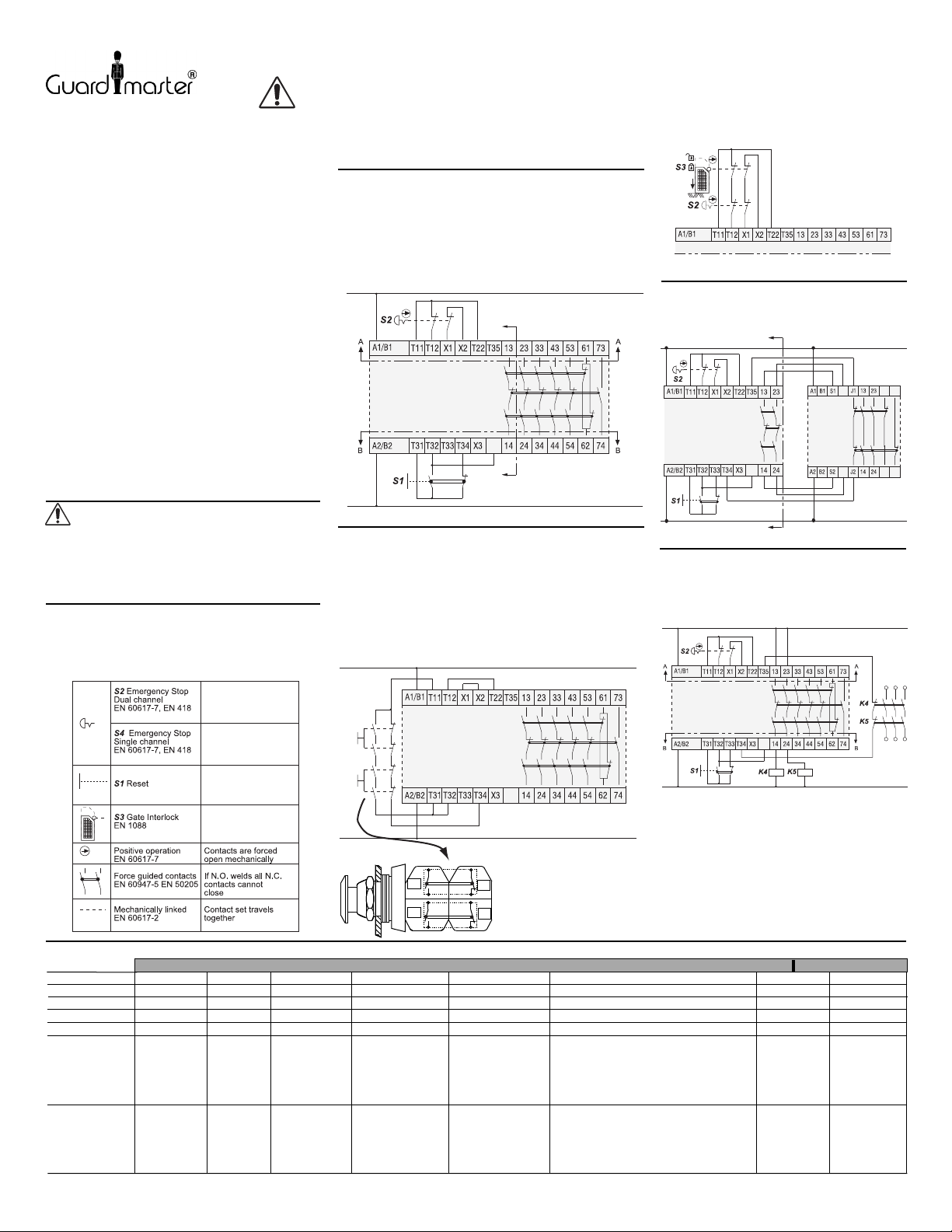
E-Stop (Fig. 1)
a) Use an E-Stop button conforming to EN 418. It must have (2)
Normally Closed (N.C.) contact blocks. The contact blocks
must conform to EN 60947-5-1 positive-opening operation.
b) Use a start/reset momentary pushbutton with a single contact
block with (2) circuits (1) Normally Open (N.O.) and (1) N.C.
If two separate blocks are used, the N.O. must be assembled
to the operator first and the N.C. assembled on it, so that if the
N.O. welds, the N.C. will be held open and a fault detected
(See Fig. 2B)
Two-Hand Control (Fig. 2A)
This device conforms to the requirements of EN574 IIIC of less
than 0.5 sec. of synchronous actions of two buttons. Use only
pushbuttons with two direct-opening contact blocks; each
contact block must have a N.O. and N.C. If four separate blocks
are used, the N.O. must be assembled to the operator first, and
the N.C. assembled onto it, so that if the N.O. welds, the N.C.
will be held open and a fault detected (See Fig. 2B). The
two-hand buttons and safety relay must be installed in the
same enclosure (IP54 minimum). Wires leading from the
two-hand buttons to the relay must be separated to prevent
undetected shorts between lines.
.
MSR18T
Auxiliary Relays
C
IF1
C
Fig. 1
INSTRUCTION SHEET
Gate Interlock (Fig. 3)
MSR18T
Fig. 3
Attaching an Expander Relay (Fig. 4
The expander can be used with E-Stop, Gate
Interlock
and Two-Hand Control.
MSR18T
Attaching Auxiliary Relays (Fig. 5
The auxiliary relays must be of the "positively-guided/
Direct DriveTM" style conforming to EN 50205. The
auxiliary relays may be monitored by connecting
N.C. contacts in series to the reset circuit.
MSR18T
C
IF1
C
Fig. 4
IF1
MSR19E
)
)
101
91
S3
k1
k2
S4
102
91
Refer to Guardmaster
Catalogue
Refer to Guardmaster
Catalogue
,
LEDs: Run & Fault Conditions (Fig. 1,3,4,5)
INPUT SHORT
POWER
RUN
INPUT FAULT
OUTPUT FAULT
CONDITION
ACTION
l l
l l
l
l
l
Waiting for
start signal.
None None Release
l
l
l
Proper
running
conditions.
Proper running
conditions
but start
button may be
actuated or
welded.
start button
or replace
start contacts.
Drg No: 23872 / Issue No: 1 (Ref. 40063-240-01 (A))
l
l
l l
l
l
Start button may
be in actuated
position or
welded.
Release start
button or replace
start contacts.
l
l
l
l
MSR18T
NO
NO
IF1
Fig. 2A
NC
Fig. 2B
NC
l
l
l
E-Stop contacts
may be welded
(channel 1) or
jumper wire
(T11-T22) may be
disconnected.
Replace (channel 1)
contact block or
secure jumper
wire.
Maintenance
The relay and its application must be inspected
periodically based on environmental and
operating conditions. Causes of contamination
must be eliminated. Worn and broken assemblies
must be replaced. Fasteners must be securely
re-tightened. Unit has no customer serviceable
parts. Fault c
restoring power.
control system under controlled conditions.
onditions must be corrected before
l
l
l
l
ll
1. Output circuits are welded on
the monitoring relay, expander
module or auxilliary relays or
2. resettable fuse is open or
3. start N.C. contacts may be open or
4. wire (T11-T22) may be disconnected.
1. Replace safety relay, expander
(if used), or auxillary relays (if used) or
2. after clearing short, power must be off
20 sec. to reset fuse or
3. replace start contacts or
4. secure jumper wire.
Fig. 5
After maintenance, test the
STOP ACTUATEDSTOP RESET
l
l
l
ll
l
Input short
circuit has
caused
resettable
fuse
to open.
After clearing
short, power
must be
off 20 sec.
to reset fuse.
l
l
l
l
l
Waiting for
start signal.
Reset E-stop
or gate before
actuating start.
 Loading...