

Page 1
MINOTAUR
MSR12T
(b) Description
The unit will compare the switched inputs at S13-S14 and S23-S24. In
the event of a disparity between the inputs for more than 0.5 secs, the
unit will lock out the outputs to the OFF state. Normal operation can only
be resumed after both inputs are open and then closed synchronously
(within 0.5secs).
(a)
MONITORING SAFETY RELAY
ÜBERWACHUNGS-/SCHUTZRELAIS
RELAIS DE SECURITE POUR CONTROLE
Beschreibung
Das Gerät vergleicht die Schalteingänge zwischen S13 - S14 und S23 und
S24. Bei einer eventuellen Diskrepanz dieser Eingänge für mehr als 0,5
Sekunden, versetzt das Gerät die Ausgänge in den Sperrzustand AUS. Der
normale Betrieb kann erst nach Öffnen und synchronem Schließen beider
Eingänge (innerhalb von 0,5 Sekunden) wiederaufgenommen werden.
Description
L’appareil compare les entrées commutées aux bornes S13-S14 et S23S24. En cas de disparité entre les entrées pendant plus de 0,5 seconde,
l’appareil bloque les sorties hors circuit (OFF). Le fonctionnement normal
ne reprend que lorsque les deux entrées sont ouvertes puis fermées en
synchronisation (dans un délai de 0,5 seconde).
(c) Installation Instructions Notice D'installation
RETAIN THESE INSTRUCTIONS
Installation must be in accordance with the following steps and must be
carried out by suitably competent personnel.
This device is intended to be part of the safety related control system of a
machine. Before installation, a risk assessment should be performed to
determine whether the specifications of this device are suitable for all
foreseeable operational and environmental characteristics of the machine
to which it is to be fitted.
At regular intervals during the life of the machine check whether the
characteristics foreseen remain valid.
Guardmaster cannot accept responsibility for a failure of this device if the
procedures given in this sheet are not implemented or if it is used outside
the recommended specifications in this sheet.
Exposure to shock and/or vibration in excess of those stated in IEC 68
part: 2-6/7 should be prevented.
Adherence to the recommended inspection and maintenance instructions
forms part of the warranty.
Deutsch /
(a) ÜBERWACHUNGSBEISPIELE -
Verwendung des MSR12T zur
Erfassung eines einzelnen Fehlers /
EXEMPLES DE CONTROLE – MSR12T est
utilisé pour contrôler un défaut unique
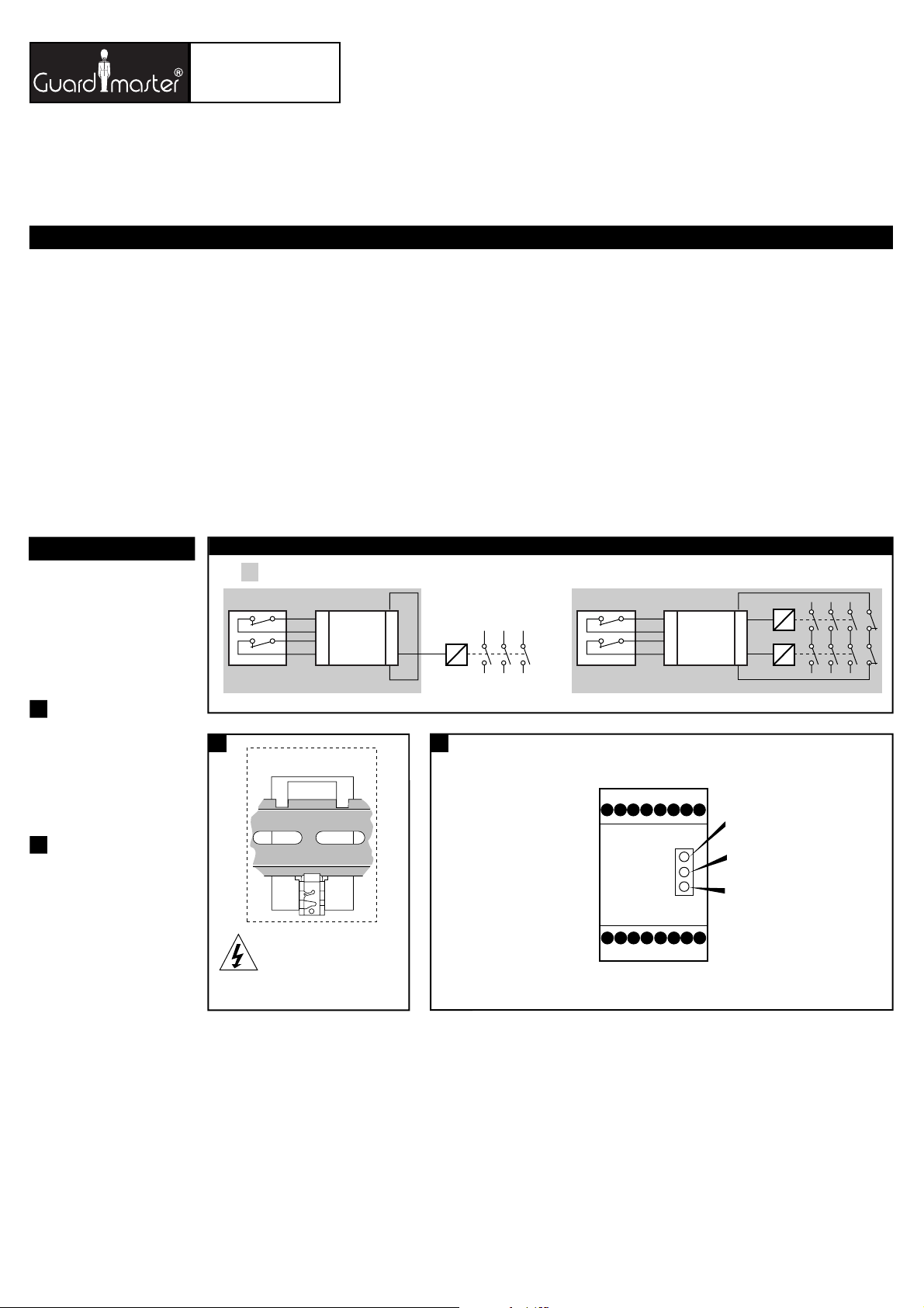
(b) EINGANG /
(c) AUSGANG /
(d) Zeigt an, welche Funktion das MSR6R/T
überwacht /
contrôle
Français
ENTREE
SORTIE
Indique ce que MSR6R/T
(a) MONITORING EXAMPLES - MSR12T used to detect a single fault
(d) Indicates what the MSR12T is monitoring
Einbauanleitung
DIESE ANLEITUNG AUFBEWAHREN
Die Installation muß unter Einhaltung der nachstehend beschriebenen
Schritte, und durch geeignetes, fachlich qualifiziertes Personal erfolgen.
Diese Vorrichtung ist als Teil des sicherheitsrelevanten Kontrollsystems
einer Maschine vorgesehen. Vor der Installation sollte eine
Risikobewertung zur Festlegung dessen erfolgen, ob die Spezifikationen
dieser Vorrichtung für alle vorhersehbaren betrieblichen und
umweltbezogenen Eigenschaften der jeweiligen Maschine geeignet sind,
an der sie installiert werden soll.
In regelmäßigen Abständen während der Lebensdauer der Maschine ist zu
überprüfen, ob die vorhergesehenen Eigenschaften weiterhin gültig sind.
Guardmaster kann keinerlei Verantwortung für ein Versagen dieser
Vorrichtung übernehmen, wenn die in diesem Schriftblatt gegebenen
Verfahrensweisen nicht implementiert wurden, oder wenn sie außerhalb
der auf diesem Schriftblatt empfohlenen Spezifikationen verwendet wird.
Eine Aussetzung an Stoßbelastungen und/oder Vibrationen, die überhalb
den in IEC 68, Teil 2-6/7 angegebenen Werten liegen, sollte verhindert
werden.
Die Einhaltung der empfohlenen Inspektions- und Wartungsvorschriften ist
Teil der Garantie.
MSR12T
(b) INPUT
(c) OUTPUT
CONSERVEZ CES INSTRUCTIONS
L’installation doit être effectuée conformément aux instructions suivantes,
par des membres qualifiés du personnel.
Ce dispositif est étudié pour être incorporé dans le système de contrôle
pour la sécurité d’une machine. Avant l’installation, on doit effectuer une
évaluation des risques pour déterminer si les spécifications de ce dispositif
sont appropriées pour toutes les caractéristiques de service et du milieu
d’utilisation prévues pour la machine sur laquelle il sera monté.
Vérifier, à des échéances régulières au cours de la vie de la machine, que
les caractéristiques prévues sont toujours valables. Guardmaster décline
toute responsabilité pour les défaillances de cet appareil si les procédures
décrites dans la présente notice ne sont pas appliquées ou si l’appareil est
utilisé hors des spécifications recommandées dans cette même notice.
Eviter toute exposition à des chocs et/ou des vibrations supérieurs à ceux
qui sont spécifiés dans la norme IEC 68 part. 1-6/7.
Le respect des instructions relatives à l'inspection, au contrôle et à
l'entretien de cet appareil rentre dans l'application de la garantie.
MSR12T
(b) INPUT
1
(a) Rückansicht /
(b) Spannung abschalten/
alimentations
(c) Auf 35mm-Normschiene anbringen /
Montage sur rail DIN 35mm
(d) In Einbaugehäuse nach mind. IP 54
montieren /
conforme au minimum à la norme IP 54
2
(b) Anschlüsse:
A1 & A2 = Spannungsversorgung (siehe
Angaben an der Seite)
S13, S14 = Schutzeingang 2 (Ruhekontakt)
S23, S24 = Schutzeingang 1 (Ruhekontakt)
X1, X2 = Ausgangs-/Schützüberwachung
13, 14 = Schutzausgang 1 (Ruhekontakt)
23, 24 = Schutzausgang 2 (Ruhekontakt)
31, 32 = Schutzausgang 3 (Ruhekontakt)
41, 42 = Hilfsausgang 1 (Ruhekontakt)
Connexions :
A1 & A2 = Alimentation (voir les renseignements
sur le côté)
S13 & S14 = Entrée de sécurité 2 (N/O)
S23 & S24 = Entrée de sécurité 1 (N/F)
X1 & X2 = Boucle de retour
13 & 14= Sortie sécurité 1 ( N/O )
23 & 24= Sortie sécurité 2 ( N/O )
31 & 32 = Sortie sécurité 3 ( N/O )
41 & 42 = sortie auxiliaire 1 (N/F)
Vue de l'arrière
Isoler les
Monter dans un coffret
(a) Back View
(b) Isolate power
(c) Mount on 35mm DIN rail.
(d) Mount in enclosure to a min. of IP 54.
(c) LED Anzeigen:
POWER (ROT) - leuchtet, wenn am Gerät
Spannung anliegt.
K1 (GRÜN) - leuchtet, wenn interne
Kontakte K1 geschlossen sind.
K2 (GRÜN) - leuchtet, wenn interne
Kontakte K2 geschlossen sind /
Voyants:
POWER (rouge): allumé lorsque l’appareil
est sous tension
K1 (vert): allumé lorsque les contacts
internes K1 sont fermés
K2 (vert): allumé lorsque les contacts
internes K2 sont fermés
(a) Connections / Anschlüsse / Connexions
21
(b)
A1 & A2 = Supply (see side for details)
S13 & S14 = Safety input 2 (N/C)
S23 & S24 = Safety input 1 (N/C)
X1 & X2 = Outputs (contactor) monitoring
13 & 14 = Safety output 1 (N/O).
23 & 24 = Safety output 2 (N/O).
33 & 34 = Safety output 3 (N/O).
41 & 42 = Auxiliary output 1 (N/C).
A1 S24S13
A2 S23S14
23 331341
24 341442X1X2
(c) OUTPUT
(c) LED Indication
POWER (RED) - Illuminated when
there is power to the unit.
K1 (GREEN) - Illuminated when
internal contacts K1 are closed.
K2 (GREEN) - Illuminated when
internal contacts K2 are closed.
Page 2
3
(a) In Einbaugehäuse nach mind. IP 54
montieren /
Monter dans un coffret
conforme au minimum à la norme IP 54
(b) Austauschsicherung, /
Fusible de rechange
4
(b) SCHUTZKREIS /
(c) ÜBERWACHUNGSKREIS /
CONTROLE
(d) TEST/RÜCKSTELLUNG /
TESTER / REARMER
CIRCUIT DE PROTECTION
CIRCUIT DE
5
(b) Verriegelungs- oder NOT-AUS-Kontrolle
mit Überwachung externer Relais mit
automatischer Rückstellung (ohne
Überwachung). /
ou commande d’arrêt d’urgence (E-STOP)
comprenant le contrôle de relais externes
avec Réarmement Automatique (non
contrôlé).
(c) SPANNUNGSVERSORGUNG /
ALIMENTATION
(d) Verriegelungsschalter oder NOT-AUS /
Interrupteur d’interverrouillage ou arrêt
d’urgence.
(e) Die Spannungsversorgung muß den
Vorschriften der EN 60204-1
entsprechen. Klemme A2 muß an die
Seite des Steuerkreises angeschlossen
werden, die mit dem Schutzleiter
verbunden ist.
ZUR BEACHTUNG: Die Ausgänge sind
durch eine externe Sicherung zu
schützen.
La tension d’alimentation doit être conforme
aux spécifications d’EN 60204-1. La borne
A2 doit être connectée au côté du circuit de
commande qui est relié au conducteur de
protection.
REMARQUE : les sorties doivent être
protégées par un fusible extérieur.
(f) Überbrücken, wenn externe
Relaisüberwachung oder -rückstellung
nicht erforderlich ist. /
contrôle ou le réarmement des relais externes
n’est pas requis.
(g) Rückstellung (ohne Überwachung), falls
gewünscht. /
lorsqu’il est spécifié.
Interrupteur interverrouillé
Relier lorsque le
Réarmement (non contrôlé),
3 4
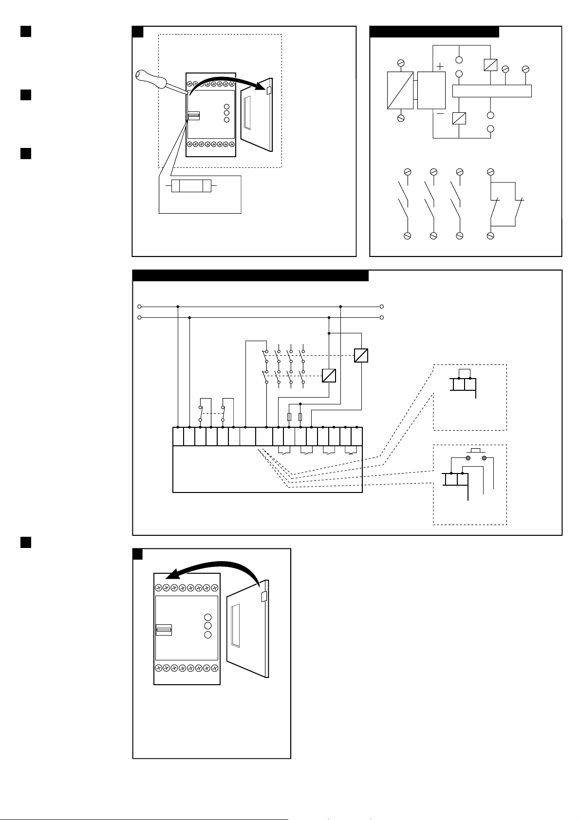
(a) Mount in enclosure to a min of IP 54.
500 mAT
(b) Fuse replacement
5
(a) Wiring example / Anschlußbeispiele / Exemples de câblage
Interlock Switch or E-STOP control with Monitoring of External Relays with Auto Reset (not monitored).
(b)
(c) SUPPLY SUPPLY
K1
K1
K2
(d) Interlock Switch
K2
or E-STOP
A1 A2
S13 S14 S23 S24
X1 X2
13 14 23 24 33 34 41 42
SUPPLY CH1 CH2
OUTPUTS
MSR12T
230VAC or 110VAC or 24V AC/DC
(e)
The supply voltage must meet the requirements of EN 60204-1. Terminal A2 must be connected
to that side of the control circuit which is connected to the protective conductor.
NOTE: Outputs should be protected by an external fuse.
(a)
Internal Circuit / Innenschaltibild / Circuit interne
S23
S24
~
=
(b)
232433
13
(c) MONITORING CIRCUIT
CIRCUIT
PROTECTION
K1
K1 K1 K1
K2 K2 K2
14
34
X1 X2
(f) Link when external
relay monitoring or reset is
not required.
X1 X2
(g) Reset (non monitored)
if required.
K2
S13
S14
41
K1 K2
42
(d) RESET
X1
X2
6
(a) Deckel wieder aufsetzen /
Remettre le couvercle sans forcer
(b) Spannung anschließen. Vor
Inbetriebnahme auf korrekte
Funktion überprüfen. /
Connectez l'alimentation - Contrôlez le
bon fonctionnement des sécurités
avant la mise en service pour la protection
des opérateurs.
6
(a)
Replace Cover.
Connect power - Check
operation before
allowing operator use.
Page 3

(d) Technical Specifications
Conforming to standards EN60204, EN954-1, EN292.
Power supply
Power consumption < 4 VA.
X1-X2 Contactor monitor loop N/C contactor loop. Automatic reset.
Safety inputs 2 N/C switches (guard closed).
Drop out time 50 m Sec. (typical)
Impulse withstand voltage 2500 V.
Over voltage category II in accordance with VDE 0110
Internal fuse 500 mAT Replaceable supply fuse.
Relay outputs 3N/O TUV approved.
Auxiliary output 1N/C (41/42) for monitoring only
Utilisation Cat. AC 15: 4 A / 250 VAC
Min. switched current / voltage 10 mA / 10 V.
Max. output fuse 5 A Quick acting on AC
Indication LED 1 Red 1 = Power On.
LED 2 Green = K1 closed
LED 3 Green 2 = K2 closed
Operating temperature -10°C to +55°C.
Pollution degree 3 DIN VDE 0110
Humidity 90% at +50°C.
Protection class N/A. Mount in IP 54 min. enclosure
Sealing Enclosure: IP 40 DIN 0470.
Terminals 1x2.5mm
Conductor fixing Plus-minus terminals screws M3.5
Housing 16 Way D=120, H=73, W=45.5mm.
Weight 510g.
Material and colour Polycarbonate, red .
Installation group C in accordance with VDE 0110.
Fixing details 35mm DIN rail.
Torque settings - Terminal screws 1.0Nm (0.79lbs/in)
24 VAC/DC, 110 VAC or 230 VAC. (±10%)
(13/14, 23/24, 33/34)
DC 13: 3 A / 24 VDC
3 A Quick acting on DC
Terminal: IP 20 DIN 0470.
2
stranded with sleeves
stripped 8mm, 1x4 mm
2
solid conductor.
(UL = 16 - 18 American wire gauge)
120
35MM DIN RAIL MOUNTING / 35mm DIN-Schienen montage / Montage sur rail DIN 35mm
Konformität mit folgenden Normen EN60204, EN954-1, EN292.
Leistungsversorgung 24 VAC/DC, 110 VAC oder 230 VAC (± 10%)
Leistungsaufnahme < 4 VA
Schütz-Überwachungsschleife X1-X2 Schütz-Schließscheife Automatische
Schutzeingänge 2 Öffnungsschalter (Schutztür geschlossen)
Abfallverzögerung 50 ms (typisch)
Bemessungs-Stoßspannung 2500 V
Überspannungsklasse II gemäß VDE 0110
Interne Sicherung 500 mAT, austauschbare Netzsicherung
Relaisausgänge 3 Schließer mit TÜV-Zulassung
(13/14, 23/24, 33/34)
Hilfsausgang 1 Schließer (41/42), nur für Überwachung
Anwendungsklasse AC 15: 4 A / 250 V AC
DC 13: 3 A / 24 V DC
Min. Schaltstrom/Schaltspannung 10 mA / 10 V
Max. Ausgangssicherung 5 A Flinksicherung für AC
3 A Flinksicherung für DC
Anzeigen LED 1 Rot 1 = Strom EIN
LED 2 Grün = K1 geschlossen
LED 3 Grün 2 = K2 geschlossen
Betriebstemperaturbereich - 10°C bis +55°C
Verschmutzungsgrad 3, gemäß DIN/VDE 0110
Luftfeuchtigkeit 90% bei +50 °C
Schutzklasse n/z. Einbau in Gehäuse mit
Isolation Gehäuse: IP 40, DIN 0470
Klemmenleiste: IP 20, DIN 0470
Klemmeneingänge 1 x 2,5 mm
freigelegt 8 mm, 1 x 4 mm
(UL = 16 - 18, U.S.- Drahtmaß)
Leiterbefestigung Plus-/Minus-Schraubklemmen, M3,5
Gehäuse 16 Eingänge, 120 (T), 73 (H),45,5 mm (B)
Gewicht 510 g
Material und Farbgebung PC, rot
Installationsklasse C, gemäß VDE 0110
Montage auf 35 mm DIN-Schiene
Anzugsdrehmoment für
Schraubklemmen 1,0 Nm (0,79 lbs/in)
Rückstellung
mindestens IP 54
2
verseilter Leiter mit Muffen
2
Massivleiter.
45.5
73.0
Spécifications TechniquesTechnische Daten
Conforme aux normes suivantes EN 60204-1, EN954-1, EN592
Alimentation 24V c. alternatif / c. continu, 110 ou
Puissance consommée < 4A
Circuit de contrôle du contacteur X1-X2 Circuit de contacteur n/c ou
Entrées de sécurité 2 N/F (panneau de protection fermé)
Temps de désexcitation: 50 msec (moyen)
Tension de régime de l’impulsion 2500 V
Catégorie de surtension II conformité VDE 0110
Fusible interne Fusible remplaçable 500 mAT
Sorties de relais 3 N/O homol. TUV
Sortie auxiliaire 1 N/F (41/42) pour le contrôle
Catégorie d’utilisation C. altern. : 15 : 4 A / 150 V c. alternatif
Courant/tension interconnecté minimum 10 mA / 10 V
Puissance de sortie maxi du fusible 5 A à action rapide sur c. alternatif
Voyants Voyant 1 Rouge = Sous tension
Voyant 2 Vert = K1 fermé
Voyant 3 Vert = K 2 fermé
Température de service -10°C à +55°C
Niveau de contamination 3 DIN VDE 0110
Humidité 90% h.r. à +50ºC
Degré de protection du boîtier S/O. Monter dans boîtier IP 54 min.
Isolation Boîtier : IP40 DIN 0470
Bornes 1 de 2,5 mm
Fixation du conducteur Bornes filetées plus/moins M3,5
Boîtier 16 voies Prof.x h. l. = 120 x 73 x 45,5 mm
Poids 510 grammes.
Matériaux et couleur polycarbonate, rouge
Groupe d’installation C conf. VDE0110
Fixation Rail DIN de 35 mm
Couple – Bornes filetées 1,0 N (0,79 lbs/in)
230 V c. alternatif (±10%)
réarmement contrôlé. Réarmement
automatique
(13/14, 23/24, 33/34)
seulement
C. continu : 13 : 3 A / 24 V c. continu
3 A à action rapide sur c. continu
Borne : IP20 DIN 0470
2
toronnée avec gaines
dénudées sur 8 mm, fil unique de 4 mm
(UL = 16 – 18 AWG)
2
Page 4

(e) USE UTILISATION
The MSR12T checks for single faults of dual channel safety circuits when the
switching devices such as guard interlocks and E-Stops are operated (refer to
'Monitoring examples'). For E-Stops (& interlocks infrequently used) a weekly
operational check of these switches should be carried out as part of the
regular maintenance programme.
Fault detection characteristics
Single fault Circuit condition Checked at..
Open circuit Switch closed immediately.
Closed circuit Switch closed at next opening of the guard.
Open circuit Switch open at next closing of the guard.
Closed circuit Switch open immediately.
.
(f) MAINTENANCE INSPECTION ET MAINTENANCE
At least every 6 months
Isolate all power! Check for correct terminal connections and check wiring for
signs of damage. Check the unit locks out when a single fault occurs by
placing a link across S13 & S14. Ensure all interlocked guards are closed.
Reinstate power to the MSR12T, press the reset button (if fitted) and open
one interlocked guard door (or operate E-Stop). Check that the MSR12T locks
out. Isolate all power! Remove the link and repeat the test across S23 &
S24. If there are multiple devices monitored by the Minotaur, repeat these
tests for each device in turn. During tests check LED's are operating correctly.
Der MSR12T überwacht auf einzelne Fehler in zweikanaligen
Sicherheitskreisen, wenn Schaltgeräte wie Schutztürschalter und NOT-AUSEinrichtungen betätigt werden (Siehe Überwachungsbeispiele.). Bei NOT-AUSEinrichtungen (und selten betätigten Schutztürschaltern) ist eine wöchentliche
Überprüfung als Teil des regelmäßigen Wartungsprogramms auszuführen.
Eigenschaften der Fehlerentdeckung
Einzelner Fehler Stromkreiszustand Geprüft wann
Unterbrechung Schalter geschlossen sofort
Schluß Schalter geschlossen nächste Betätigung der Schutztür
Unterbrechung Schalter offen nächste Betätigung der Schutztür
Schluß Schalter offen sofort
PRÜFUNG UND WARTUNG
Wenigstens alle 6 Monate
Spannung abschalten. Anschlüsse und Verdrahtung auf Schäden überprüfen.
Sicherstellen, daß LED's korrekt arbeiten. Prüfen, ob Gerät bei Auftreten eines
einzelnen Fehlers abschaltet, indem eine Brücke über Anschlüsse S13 und
S14 gelegt wird. Sicherstellen, daß alle Schutztüren geschlossen sind.
Spannung an Gerät legen, RESET-Knopf (falls vorhanden) drücken und eine
Schutztür öffnen (oder NOT-AUS-Knopf drücken). Prüfen, ob das Gerät
abschaltet. Spannung abschalten. Test an Anschlüssen S23 und S24
wiederholen. Falls mehrere Schaltgeräte vom MINOTAUR überwacht werden,
den Test für jedes Gerät einzeln wiederholen. Während des Tests darauf
achten, ob die LED's korrekt arbeiten.
(g) REPAIR
Repair is limited to the internal replaceable fuse.
If there is any malfunction or damage, no attempts should be made to repair
it. The unit should be replaced before machine operation is allowed.
DO NOT DISMANTLE THE UNIT.
Eine Reparatur beschränkt sich auf das Ersetzen der internen Sicherung. Falls
Fehlfunktionen oder Schäden auftreten, keine Versuche zur Reparatur
unternehmen. Der Schalter muß ersetzt werden, bevor die Maschine wieder
gestartet wird.
GERÄT DARF NIEMALS GEÖFFNEN WERDEN!
BETRIEB
REPARATUR
Le Minotaur MSR12T contrôle les fautes simples sur des circuits de sécurité en
service à deux canaux comme les interverrouillages, les arrêts d’urgence (
exemples de contrôle)
faiblement utilisés), un programme d’inspection régulier hebdomadaire doit
obliger à manoeuvrer l’appareil.
Caractéristiques des pannes
Faute simple Etat du circuit A contrôler
Circuit ouvert contact fermé Immédiatement
Circuit fermé contact fermé à la prochaine ouverture du protecteur
Circuit ouvert contact ouvert à la prochaine fermeture du protecteur
Circuit fermé contact ouvert immédiatement
A faire tous les 6 mois
Couper l’alimentation. Vérifier le serrage des bornes et les signes de
dommages sur le câblage. Contrôlez l’allumage correct des lampes. Vérifier
que l’unité fonctionne bien en plaçant un strap entre les bornes S13 & S14.
Vérifier que toutes les portes sont fermées. Remettre l’alimentation, réarmer
par bouton (si existant), manoeuvrer une porte (ou un arrêt d’urgence) .
Contrôler que le MSR12T fonctionne bien. Couper l’alimentation. Retirez le
strap et refaire la même opération avec les bornes S23 & S24. Si plusieurs
appareils sont câblés sur le même bloc logique, manoeuvrer les à tour de rôle.
Après le test, couper l’alimentation et retirer le strap.
. Pour les arrêts d’urgence (et les interverrouillages
REPARATION
Il n'y a que le fusible interne qui peut être remplacé. Dans l'éventualité
d'un problème technique ou d'une détérioration de cet appareil,
il doit être remplacé immédiatement avant la remise en production de la
machine.
DANS TOUS LES CAS, NE DISLOQUEZ PAS L'APPAREIL.
Voir des
(h) TROUBLESHOOTING CONSEIL EN CAS DE PANNE
FEHLERSUCHE
LED Status
Symptom
Output contacts fail to close
Output contacts fail to close
Output contacts fail to close
Output contacts fail to close
Power K1 K2
OFF OFF OFF
ON ON OFF
ON OFF ON
ON OFF OFF
Cause
Fault on power supply to Minotaur or, voltage overcurrent - internal fuse blown or, short circuit between input circuits - internal fuse blown.
Fault on input circuit
Fault on input circuit
Fault on output, output monitoring or input circuits.
If an internal fault to the Minotaur is suspected please contact the supplier. Do not dismantle the unit.
LED Status
Symptom
Ausgang schließt nicht
Ausgang schließt nicht
Ausgang schließt nicht
Ausgang schließt nicht
Power K1 K2
Aus Aus Aus
An An Aus
An Aus An
Aus Aus Aus
Ursache
Fehler an Spannungsversorgung oder Überlast - interne Sicherung zerstört; oder Schluß zwischen internen Stromkreisen - interne Sicherung zerstört
Fehler am Eingangskreis
Fehler am Eingangskreis
Fehler am Ausgangskreis, Überwachungskreis oder Eingangskreis
Bei Verdacht auf einen internen Fehler des Minotaur, sich bitte an Ihren Händler wenden. Das Gerät darf niemals geöffnet werden!
Etat des LED
Symptôme
Les contacts de sortie refusent de se fermer
Les contacts de sortie refusent de se fermer
Les contacts de sortie refusent de se fermer
Les contacts de sortie refusent de se fermer
Power K1 K2
OFF OFF OFF
ON ON OFF
ON OFF ON
ON OFF OFF
Cause
Panne sur alimentation ou surtension ou rupture fusible ou court-circuit sur entrées.
Panne sur circuit d’entrée
Panne sur circuit d’entrée
Panne sur entrée ou sortie ou auto-contrôle ou câblage.
Si une panne interne apparaît sur un composant du système MINOTAUR, contactez le fournisseur. NE JAMAIS DISLOQUER L’APPAREIL.
Drg No: 23893 / Issue No: 3
R
 Loading...