

Page 1
INSTALLATION INSTRUCTIONS / MONTAGEANLEITUNG / NOTICE D'INSTALLATION
EN 60204, BS EN 292.
24V AC/DC and 110/230
VAC selectable.
<4VA.
110/230 VAC 500mA replaceable supply
fuse. 24V AC/DC 500mA resettable fuse
110/230 VAC selector.
Normally closed contactor loop
monitoring and reset.
2 N/O switches.
8 N/O 1N/C instant and
1 N/O 1 N/C delay output.
4 A/250VAC / 1000 VA.
2 A /30VDC / 60W.
Red: Power on.
Green 1: S13 - S14 closed.
Green 2: S23 - S24 closed.
Green 3: Delay output closed.
50m sec - Immediate outputs
10 sec (+50m sec) - Delay outputs.
>10
6
operations.
-10°C to +55°C.
IP 40.
IP 20.
32 way D=120mm H=73mm
W=152mm.
Red polycarbonate.
35mm DIN rail.
Max. 5A quick blow fuse.
Delay time is set by internal
variable resistor.
Conforms to:
Supply voltage:
Power consumption:
Internal fuse:
Internal switches:
Terminals X1-X2 :
Safety inputs:
Relay outputs:
Maximum switched:
Current/Voltage/Load:
Indication LED 1:
LED 2:
LED 3:
LED 4:
Drop out time:
Mechanical life:
Ambient temperature:
Degree of
enclosure protection:
Degree of
Terminal protection:
Housing:
Material and colour:
Fixing Details:
External output fuse:
Miscellaneous:
DIN EN 60204/VDE 0113, DIN 292.
Polycarbonat, rot, 32 Klemmen,
152 x 73 x 120 mm.
Schnellbefestigung auf DIN-Normschiene.
Gehäuse IP40, Anschlüsse IP20.
24V AC/DC und 110/230V AC
(umschaltbar).
< 4 VA.
110/230VAC 500mA Ersatzsicherung
24V AC/DC 500mA rückstellbare Sicherung
Umschalter 110/230V AC.
2 Öffnerkontakte.
8 Schließer / 1 Öffner unverzögert
1 Schließer / 1 Öffner unverzögert.
Max. 5 A flink an Ausgängen.
Schützhilfskontakte und Reset.
Max. 4 A / 250V AC / 1000V A; 2 A.
Rot = Betriebsspannung
Grün 1 = S13-S14 geschlossen
Grün 2 = S23-S24 geschlossen
Grün 1 = verzögerter Ausgang geschlossen.
50 ms (unverzögert
50 ms + 0... 10 s (verzögert).
-10°C bis +55°C.
> 10
6
Schaltspiele.
Vorschriften:
Gehäuse:
Montage:
Schutzart:
Betriebsspannung:
Leistungsverbrauch:
Interne Sicherung:
Interne Schalter:
Eingänge:
Ausgänge:
Externe Sicherung:
Anschlüsse X1-X2:
Schaltleistung:
Anzeige LED 1:
LED 2:
LED 3:
LED 4:
Abfallzeit:
Betriebstemperatur:
Mechanische Lebensdauer:
EN 60204, EN 292.
24V AC/DC & 110/230 VAC
à sélectionner.
< 4VA.
110/2330 V ca - fusible remplaçable
500 mA. 24 V ca/cc - fusible rèarmable
500 mA
110/230 VAC à selectionner.
Boucle de retour pour contrôle
et réarmement.
2 contacts N/O.
8 N/O + 1 N/C instantanés
1 N/O + 1 N/C temporisés.
4A/250VAC/1000VA.
2A/30VDC/60W.
Rouge Alimentation ON
Verte 1 S13 - S14 fermée
Verte 2 S23 - S24 fermée
Verte 3 Sortie temporisée fermée.
50mS pour les sorties instantanées
10 S + 50ms pour les sorties temporisées.
>1000000 opérations.
-10°C à +55°C.
IP 40.
IP 20.
32 voies P=120mm, H=73mm,
L=152mm.
Polycarbonate rouge.
Rail Din 35mm.
Max 5A à fusion rapide.
Résistance variable interne.
Conforme:
Alimentation:
Consommation:
Fusible interne:
Switch interne:
Bornes X1 - X2:
Entées de sécurité:
Contacts de sortie:
Pouvoir de coupure max:
Charge/courant/tension:
Lampes LED1:
LED2:
LED3:
LED4:
Temps de réponse:
Vie mécanique:
Température ambiante:
IP Boîtier:
IP Bornier:
Boîtier:
Matériaux et couleur:
Fixation:
Fusible de sortie externe:
Réglage temporisation:
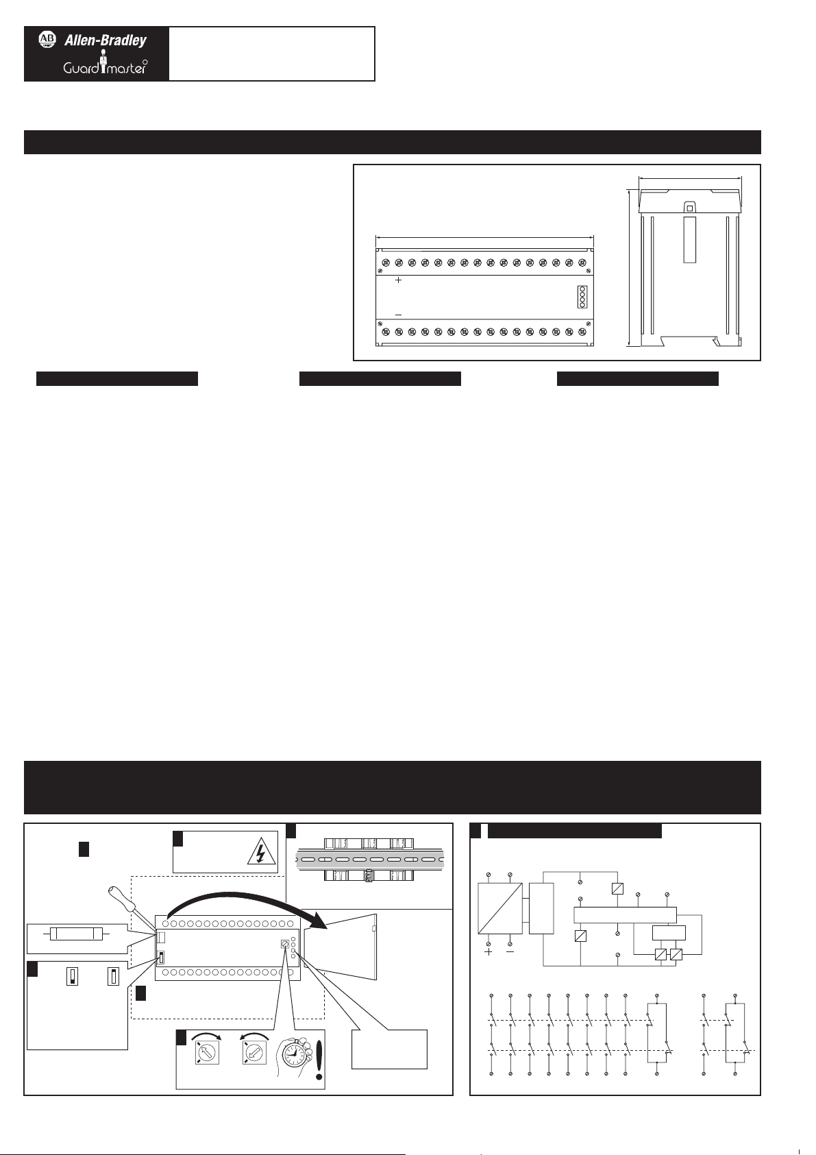
Technical Specifications
Technische Daten
Specifications Techniques
Fuse replacement
Mount in enclosure to a min of IP 54.
In Gehäuse mit mind. IP 54 anbringen.
A monter dans coffret minimum IP 54.
500 mAT
Isolate power.
Spannung abschalten.
Isoler les alimentations.
Mount on 35mm DIN rail / Auf 35mm-Normschiene
anbringen / Montage sur rail DIN 35mm
Back Veiw / Rückansicht / Vue arrière
Indicator lights.
Anzeigeleuchten.
Lampes de signalisation.
Remove cover.
Deckel abnehmen.
Ouvir le couvercle
sans forcer.
A2
~
=
Protection
Circuit
X1
S13
S14
INPUT 1
TEST
RL2
RL3 RL4
RL1
X2
A1
24V AC/DC Supply
110/230 VAC Supply
S23
S24
INPUT 2
Monitoring Circuit
Delay
Internal Circuit / Innenschaltbild / Circuit interne2 7
4
6
1
3
13
RL1
14232433344344535463647374
83 91
84 92
D13 D21
D14 D22
RL2
RL3
RL4
Multi Output Monitoring Safety Relay With Timed Delay Outputs
Relais-Sicherheitsbaustein mit mehreren Susgängen,
2 Ausgänge zeitverzögert
Relais auto-contrôlé multi-sorties avec temporisation pour arrêt
d'urgence et système de sécurité machine
Fully CW
Minimum 0s
Fully CCW
Maximum 10s
This unit has dual channel operation and requires the simultaneous closing (within 0.5 secs) of the input
circuits S13 - S14 & S23 - S24 to close the 8 immediate action outputs 13 - 14 to 83 - 84.
If an OFF delay is required, a timed delay of 0 to 10 secs can be set for terminals D13 - D14 for N/O or
D21 - D22 for N/C.
Ce bloc logique de sécurité possède deux canaux d'entrée qui doivent se fermer simultanément dans un
laps de temps de 0.5 secondes (Circuits S13-S14 & S23-S24). Ils pilotent immédiatement à la fermeture 8
contacts de sécurité (circuits 13-14 à 83-84). Si une temporisation à la retombée est nécessaire, elle est
configurable de 0 à 10 secondes, disponible entre les bornes D13-D14 en contact N/O, disponible entre
les bornes D21-D22 en contact N/C.
Dieses Gerät ist zweikanalig und erfordert das gleichzeitige Schließen (innerhalb von 0,5 s) der
Eingangskreise S13-S14 und S23-S24 zum Aktivieren der acht unverzögerten Ausgänge 13-14 bis 83-84.
Falls eine Zeitverzögerung benötigt wird, kann ein Wert zwischen 0 und 10 s für die Anschlüsse D13-D14
(Schließer) oder D21-D22 (Öffner) eingestellt werden.
Drg No. 23638
Select voltage before connection.
Vor Anschluß Spannung einstellen.
Sélectionner la tension
d'alimentation désirée.
Selectable
110VAC
230VAC
D21D1391
Power
K1
K2
Off Delay
837363534333
152.0mm
2313X1S13A1 S23
D22D14928474645444342414X2S14A2
S24
73.0mm
120mm
NOTE: Follow steps 1 to 12 for correct installation. All work should be carried out by suitably competent personnel.
ANMERKUNG: Zwecks korrekter Installation Schritte 1 bis 12 abarbeiten. Alle Arbeiten sind von qualifiziertem Elektro-Personal auszuführen.
NOTE: Suivre les étapes 1 à 12 pour une installation correcte. Cette installation doit être sous la responsabillité d'une personne compétente.
5
MINOTAUR
MSR10RD
R
Page 2
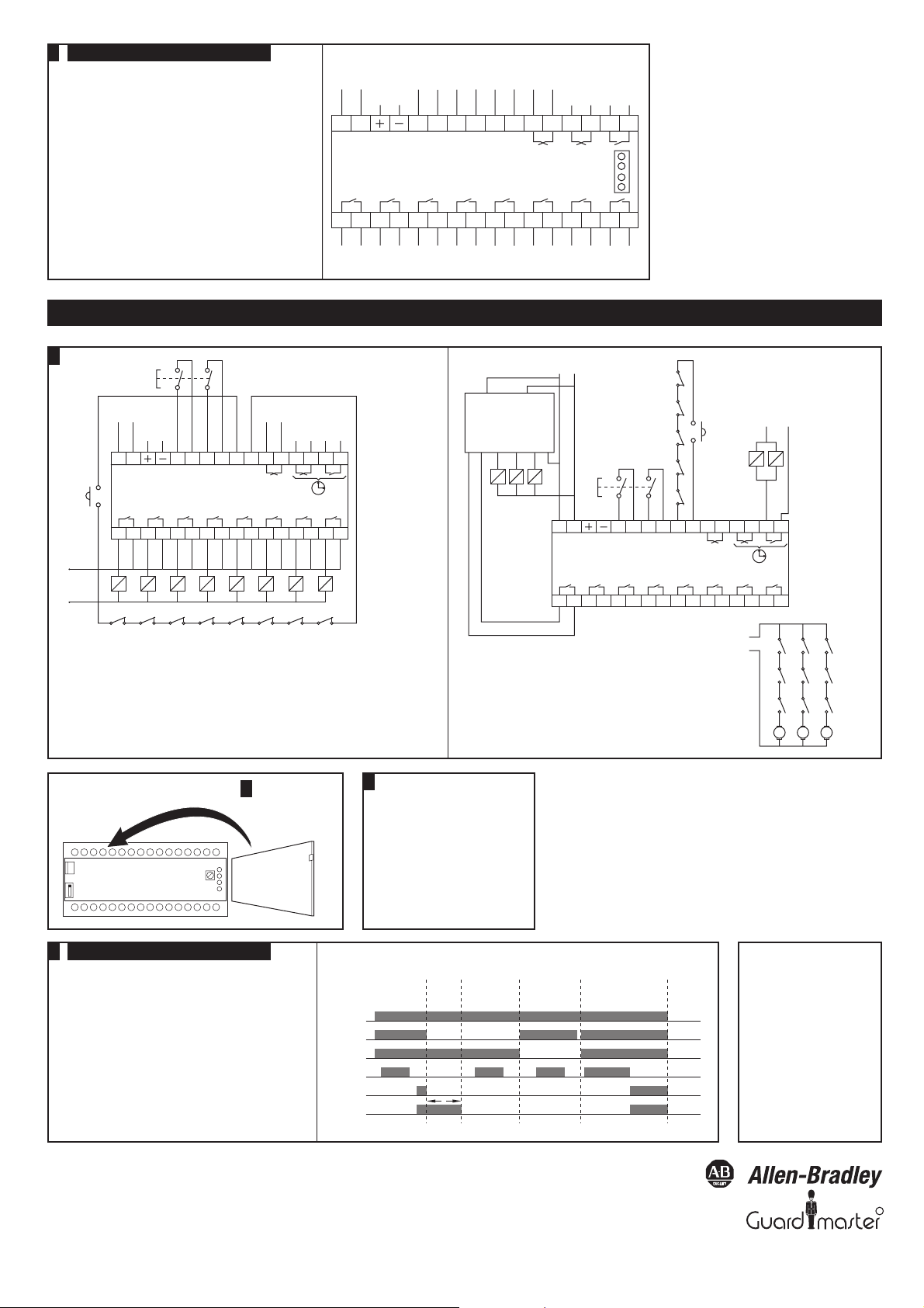
APPLICATIONS EXAMPLES / APPLICATIONS EXAMPLES / EXEMPLES D'APPLICATIONS
Drawing No. 23889 Issue No. 2
Change No: 25020
Wiring Connection / Verdrahtung / Raccordements8
NOTE: When using the timed delay output option
for isolation in the event of failure, the response
time of the unit will be the value set at the timer. This is
important to note if the unit response time is required
for the calculation of separation distances.
ANMERKUNG: Wenn der zeitverögerte Ausgang
zum Abschalten im Fehlerfall benutzt wird, ist die
Ansprechzeit des Geräts gleich dem an der Zeitverzögerung
eingestellten Wert. Dies ist wichtig, wenn die Ansprechzeit
des Geraäts für die Berechnung der Mindestabst benutzt
werden soll.
NOTE: Quande vous utilisez une sortie temporisée pour
couper les énergies dans le cas d'une panne interne, le temps
de réponse du relais sera le temps de valeur de présélection.
Ce temps doit être pris en compte pour calculer les distance
d'arrêt.
13
MSR 10RD
NORMALLY OPEN NON-COMMITED CONTACTS
14 23 24 33 34 43 44 53 54 63 64 73 74 83 84
A1 A2 S13 S14 S23 S24 X1 X2 91 92 D21 D22 D13 D14
230 VAC
110 VAC
SAFETY
INPUT 1
SAFETY
OUTPUT 3
SAFETY
OUTPUT 2
SAFETY
OUTPUT 1
SAFETY
OUTPUT 6
SAFETY
OUTPUT 5
SAFETY
OUTPUT 8
SAFETY
OUTPUT 7
SAFETY
OUTPUT 4
SAFETY
INPUT 2
AUX
OUTPUT 1
MONITORED
RESET
LOOP
24V
AC/DC
N/C
DELAY
OUTPUT
N/O
DELAY
OUTPUT
Power
K1
K2
Off Delay
K1
K1 K2 K3 K4 K5 K6 K7 K8
Monitored
Reset
230 VAC
110 VAC
E-Stop or
guard interlock
K2 K3 K4
NORMALLY CLOSED POSITIVELY GUIDED AUXILIARY CONTACTS
Multi output - E stop or guard interlock switch without guard locking
- Timed delay outputs not used - circuit monitoring.
Mehrfacher Ausgang - NOT-AUS oder Schutztürschalter ohne Zuhaltung
- Zeitverzögerte Ausgänge nicht benutzt - Stromkreisüberwachung.
Multi-sorties - Arrêt d'urgence ou interverrouillage pour protecteur
- Sort ies temporisées non utilisées - Circuit de contrôle.
K5 K6 K7 K8
External outputs to be
fuse protected max
5A quick blow.
Sicherung extern in
Ausgänge (max. 5A fl.)
Les sorties doivent être
protégées sur bornier par
un fusible ultra rapide de
5A maximum.
N/C
Contactor
Supply
N/C
Delay
N/O
Delay
24V
AC/DC
13
MSR 10RD
NORMALLY OPEN NON-COMMITED CONTACTS
14 23 24 33 34 43 44 53 54 63 64 73 74 83 84
A1 A2 S13 S14 S23 S24 X1 X2 91 92
D21 D22 D13
Delay
D14
E-Stop or
guard interlock
Dual channel input E stop or guard interlock switch without guard locking
- used with PLC to provide back up isolation - circuit monitoring.
2-kanaliger NOT-AUS oder Schutztürschalter ohne Zuhaltung - mit SPS eingesetzt,
um sicheres Abschalten zu liefern - Stromkreisüberwachung.
Arrêt d'urgence ou interverrouillage pour protecteur câblé en deux canaux redondants utilisé avec commande numérique ou automate programmable pour assurer la sécurité Circuit de contrôle.
Connect power - Check for correct operation of
function and timer before allowing operator use.
Spennung anschließen - vor Einsatz auf
einwandfreie Furktion und Zeitverzögerung
überprüfen.
Enclencher l'alimentation - Vérifier le bon
fonctionnement de la ligne de sécurité et de la
temporisation - Valider la mise en service.
PLC UNIT
13
MSR 10RD
NORMALLY OPEN NON-COMMITED CONTACTS
14 23 24 33 34 43 44 53 54 63 64 73 74 83 84
A1 A2
S13 S14 S23 S24
X1
K5
K4
K3
K2
K1
X2 91 92
D21 D22 D13
Supply
Supply
Input
Out
1
A1 A2
Out2Out
3
In
Delay
D14
K2K1
K3 K4 K5
Monitored
Reset
K3
K1
K2
MT1
K4
K1
K2
MT2
K5
K1
K2
Motor Supply
MT3
Single phase
motors
Replace Cover.
Deckel wieder aufsetzen.
Remettre le couvercle
sans forcer.
The MSR 10RD has 4 LEDs. Here is what each of those indicate.
1) Red Power LED ON Supply OK.
OFF Check Supply Fuse.
2) Green LED K1 ON S13 - S14 Loop Closed.
OFF S13 - S14 Loop Open.
3) Green LED K2 ON S23 - S24 Loop Closed.
OFF S23 - S24 Loop Open.
4) Green Delay LED ON Delay Outputs Operated.
OFF Delay Outputs NOT Operated.
5) K1, K2 and Delay LEDs ON Unit Functioning Correctly.
OFF Unit in a Safe State. Check Loops.
10
12
9
11
Fault Diagnosis on the MSR 10RD using the 4 LEDs
SUPPLY
UNIT OK
MSR 10RD Timing Diagram
TIME
DELAY
S13 - S14
FAULT
S23 - S24
FAULT
SUPPLY
FAULT
X1 - X2
FAULT
S13 - S14
S23 - S24
X1 - X2
OUTPUTS
DELAY
OUTPUTS
D
In the event of an internal fault
the unit must be returned to
the supplier.
Bei einem internen Fehler muß
das Gerät zur Reparatur an Ihren
Händler zurückgeschickt werden.
En cas de panne interne, retourner
l'appareil chez le fournisseur.
R
 Loading...