

Page 1
Installation Instructions
SynchLink™ Board for PowerFlex® 700S Drives with Phase II
Control
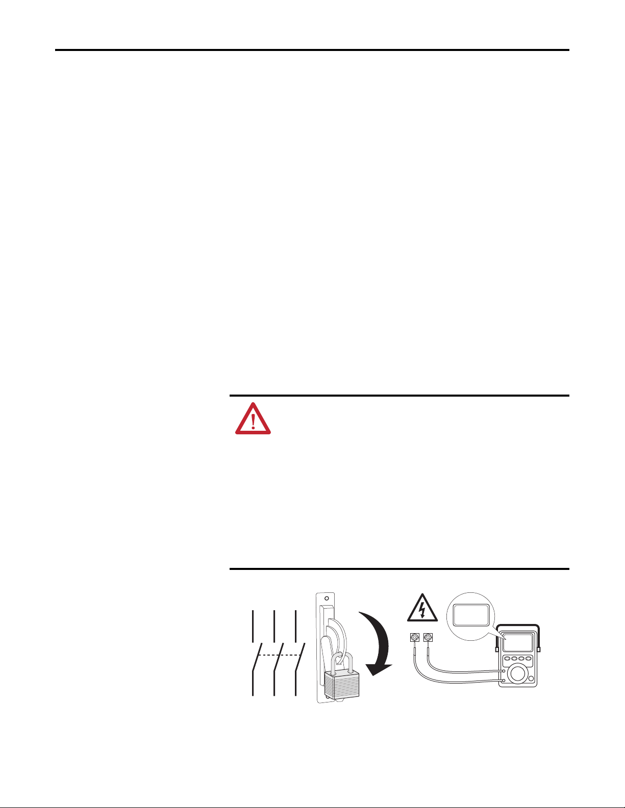
ATTENTION: To avoid an electric shock hazard, verify that the voltage on
the bus capacitors has discharged before performing any work on the
drive. Measure the DC bus voltage at the +DC & –DC terminals of the
Power Terminal Block (DC+ & DC- in high power drives). The voltage must
be zero.
ATTENTION: HOT surfaces can cause severe burns. Do not touch the
heatsink surface during operation of the drive. After disconnecting power
allow time for cooling.
ATTENTION: Hazard of permanent eye damage exists when using optical
transmission equipment. This product emits intense light and invisible
radiation. Do not look into module ports or fiber-optic cable connectors.
What This Kit Contains
Tools That You Need
ATTENTION: This drive contains ESD (Electrostatic Discharge) sensitive
parts and assemblies. Static control precautions are required when
installing, testing, servicing or repairing this assembly. Component
damage may result if ESD control procedures are not followed. If you are
not familiar with static control procedures, reference A-B publication
8000-4.5.2, “Guarding Against Electrostatic Damage” or any other
applicable ESD protection handbook.
Verify that your kit contains the items listed in the following table. If your kit
does not contain the correct items, contact your Rockwell Automation sales
representative.
Quantity: Description
1 SynchLink Board
1 “Stacker” connector
2Screws
2 Stand-offs
• Phillips® screwdriver
• POZIDRIV® screwdriver
• Standard (flat blade) screwdriver
20D-IN010B-EN-P
Phillips
®
and POZIDRIV® are registered trademarks of Phillips Screw Company
Page 2
SynchLink™ Board for PowerFlex® 700S Drives with Phase II Control
What You Need to Do
To install or replace a SynchLink board, complete the following steps:
❐ Step 1: Remove power from the drive.
❐ Step 2: Open/Remove the drive cover(s).
❐ Step 3: Remove the control cassette from the drive.
❐ Step 4: Remove the inside cover from the control cassette.
❐ Step 5: Remove the existing SynchLink board.
❐ Step 6: Install the new SynchLink board.
❐ Step 7: Install the control cassette inside cover.
❐ Step 8: Install the control cassette in the drive.
❐ Step 9: Connect the SynchLink cables.
❐ Step 10: Close/Install the drive cover(s).
❐ Step 11: Document the change.
Step 1: Remove Power
from the Drive
ATTENTION: To avoid an electric shock hazard, verify that the voltage on
the bus capacitors has discharged before performing any work on the
drive. Measure the DC bus voltage at the +DC & –DC terminals of the
Power Terminal Block. The voltage must be zero.
Remove power before making or breaking cable connections. When you
remove or insert a cable connector with power applied, an electrical arc
may occur. An electrical arc can cause personal injury or property damage
by:
• sending an erroneous signal to your system’s field devices, causing
• causing an explosion in a hazardous environment
Electrical arcing causes excessive wear to contacts on both the module
and its mating connector. Worn contacts may create electrical resistance.
L1 L2 L3
unintended machine motion
I
0V
DC+ DC–
0V
O
2 Rockwell Automation Publication 20D-IN010B-EN-P - November 2010
Page 3
SynchLink™ Board for PowerFlex® 700S Drives with Phase II Control
Step 2: Open/Remove the
Drive Cover(s)
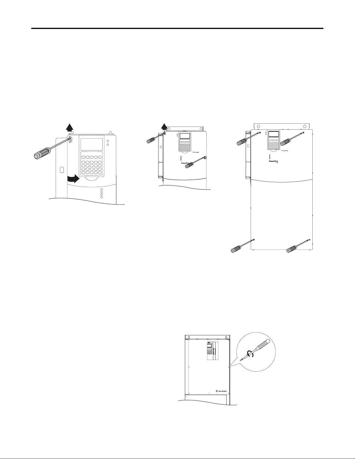
Frames 1…4 Frame 5 Frame 6
Frames 1…6
• Frames 1…4: Locate the slot in the upper left corner. Slide the locking tab
up and swing the cover open.
• Frame 5: Slide the locking tab up, loosen the right-hand cover screw and
remove the cover.
• Frame 6: Loosen the two screws on the bottom drive cover and slide the
bottom cover down and out. Loosen the two screws on the top cover and
remove the cover.
S
Frames 9…14
• Frame 9: Remove the eight POZIDRIV screws that secure the top cover
to the drive and remove the cover.
• Frame 10…14: Open the enclosure door on the bay that holds the control
frame.
Frame 9
Proper tightening torque
for reassembly is
3 N•m (27 lb•in)
Rockwell Automation Publication 20D-IN010B-EN-P - November 2010 3
Page 4
SynchLink™ Board for PowerFlex® 700S Drives with Phase II Control
Step 3: Remove the
Control Cassette from the
Drive
Loosen two screws
Frames 1…6
See page 3 for Frames 9…14 control cassette removal instructions.
1. If necessary, disconnect any fiber-optic ControlNet and SynchLink cables
from the control assembly.
ATTENTION: Hazard of permanent eye damage exists when using optical
transmission equipment. This product emits intense light and invisible
radiation. Do not look into fiber-optic ports or fiber-optic cable connectors.
2. Disconnect any remaining I/O and communications cables from the
control assembly.
3. Disconnect the ribbon cables that connect to the main control board.
4. Loosen the two screws on the front of the cassette.
5. Remove the cassette from the drive chassis.
=
Remove
cassette
Disconnect
ribbon cables
BR1
BR2
DC+
DC-
PE
U/T1
V/T2
W/T3
R/L1
L2
4 Rockwell Automation Publication 20D-IN010B-EN-P - November 2010
Page 5

SynchLink™ Board for PowerFlex® 700S Drives with Phase II Control
Frames 9…14
1. If necessary, disconnect any fiber-optic ControlNet and SynchLink cables
from the control assembly.
ATTENTION: Hazard of permanent eye damage exists when using optical
transmission equipment. This product emits intense light and invisible
radiation. Do not look into fiber-optic ports or fiber-optic cable connectors.
2. Disconnect any remaining I/O and communications cables from the
control assembly.
3. Disconnect the ribbon cables from the main control board.
4. Loosen the captive screw on the control assembly mounting plate and
swing the control assembly mounting plate away from the control frame.
Frame 9 Frames 10…14
X50
=
Loosen captive screw and swing
mounting plate away from drive.
Rockwell Automation Publication 20D-IN010B-EN-P - November 2010 5
Page 6

SynchLink™ Board for PowerFlex® 700S Drives with Phase II Control
5. Loosen the two mounting screws on the front of the control assembly and
slide the control cassette off the mounting bracket.
Frame 9 shown
=
Step 4: Remove the Inside
Cover from the Control
Cassette
• Loosen the three screws on the face of the front cover and remove the
cover.
=
Loosen three screws and remove cover
6 Rockwell Automation Publication 20D-IN010B-EN-P - November 2010
Proper tightening torque for reassembly
is 0.8… 1.1 N•m (7…10 lb•in)
Page 7

SynchLink™ Board for PowerFlex® 700S Drives with Phase II Control
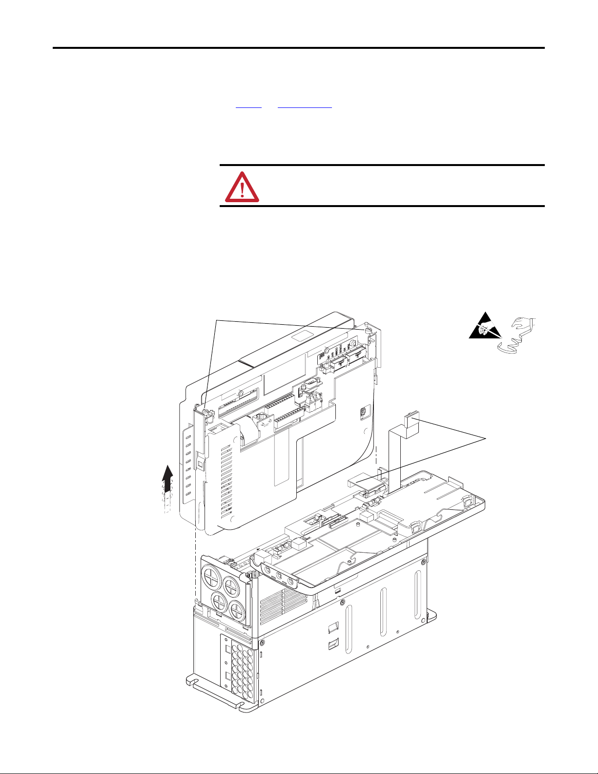
Step 5: Remove the
Existing SynchLink Board
If you are installing a new SynchLink board only, continue with Step 6: Install the
New SynchLink Board on page 8.
If you are replacing an existing SynchLink board continue with these steps.
1. Remove the two screws that secure the SynchLink board to the standoffs
on the main control board and remove the SynchLink board from the
stacker connector.
2. Remove the stacker connector from the mating connector on the main
control board.
3. Remove the two standoffs from the main control board.
=
Remove the stacker connector
Remove two standoffs
Remove two screws
and board
Rockwell Automation Publication 20D-IN010B-EN-P - November 2010 7
Page 8

SynchLink™ Board for PowerFlex® 700S Drives with Phase II Control
Step 6: Install the New
SynchLink Board
1. Secure the two standoffs to the main control board. Tighten to 0.8… 1.1
N•m (7…10 lb•in).
2. Insert the short pins
of the stacker connector into the mating connector on
the main control board. See the Important statement below.
3. Connect the mating connectors of the new SynchLink board to the long
pins of the stacker connector. See the Important statement below.
4. Secure the SynchLink board to the standoffs using the two screws
provided. Tighten to 0.8… 1.1 N•m (7…10 lb•in).
=
Install two standoffs
IMPORTANT
The end of the stacker connector with the short pins
must connect to the main control board. The end of
the stacker connector with the long pins must connect
to the SynchLink board.
Step 7: Install the Control
Cassette Inside Cover
Install the stacker connector
(see Bottom View below)
Main control board
mating connector
End with short
Stacker connector
Bottom View
Standoff
pins
End with long pins
Install two screws
to secure board to
standoffs
SynchLink board
mating connector
Install the control cassette inside cover in the reverse order of removal. Refer to
Step 4: Remove the Inside Cover from the Control Cassette
on page 6.
8 Rockwell Automation Publication 20D-IN010B-EN-P - November 2010
Page 9

SynchLink™ Board for PowerFlex® 700S Drives with Phase II Control
Step 8: Install the Control
Cassette in the Drive
Step 9: Connect the
SynchLink Cables
Install the control cassette in the reverse order of removal. Refer to Step 3:
Remove the Control Cassette from the Drive
on page 4.
Class 1 LED Product
ATTENTION: Hazard of permanent eye damage exists when using optical
transmission equipment. This product emits intense light and invisible
radiation. Do not look into module ports or fiber-optic cable connectors.
• Connect the fiber-optic cables to the J1 (transmit) and J2 (receive)
connectors on the SynchLink board. Push the plug into the socket until it
produces an audible click.
IMPORTANT
Minimum inside bend radius for SynchLink fiber-optic cable is 25.4
mm (1 in.). Any bends with a shorter inside radius can permanently
damage the fiber-optic cable. Signal attenuation increases with
decreased inside bend radii.
IMPORTANT
Do not overtighten tie-wraps.
=
J2 (Receive)
J1 (Transmit)
Rockwell Automation Publication 20D-IN010B-EN-P - November 2010 9
Page 10

SynchLink™ Board for PowerFlex® 700S Drives with Phase II Control
Step 10: Close/Install the
Drive Cover(s)
Step 11: Document the
Change
Close/Install the drive cover(s) in the reverse of removal. Refer to Step 2: Open/
Remove the Drive Cover(s) on page 3.
Document the SynchLink board installation on the “Field Installed Options”
label. Use the blank line if you are installing the SynchLink board in a drive that
was manufactured without it.
FIELD INSTALLED OPTIONS
Firmware #: Date
#: Date
Firmware
20-HIM
HIM
28-IO-
20-COMM-
20B_-DB1-
I/O
COM Module
Internal Dynamic Brake
TIP
Use the packing material from the new SynchLink board to return the
replaced SynchLink board.
10 Rockwell Automation Publication 20D-IN010B-EN-P - November 2010
Page 11

SynchLink™ Board for PowerFlex® 700S Drives with Phase II Control
Additional Information
Refer to The SynchLink Design Guide, publication 1756-TD008, when planning
and connecting the SynchLink network.
Table 1 - SynchLink Cables and Accessories
Description Cat. No.
3 M Fiber-Optic Link (Qty 2) 1403-CF 003
5 M Fiber-Optic Link (Qty 2) 1403-CF 005
10 M Fiber-Optic Link (Qty 2) 1403-CF 010
500 M Fiber-Optic Bulk 1403-CF BLK
Termination Kit 1403-NTOL
Connector (Qty 10) 1403-N10
Splice Bushing (Qty 5) 1403-N11
Pulling Bullet 1403-N12
Fiber Stripper Tool 1403-N13
SynchLink Fiber-Hub, 1 input, Base 1751-SLBA
SynchLink Fiber-Hub, 4 output, “Star” Splitter 1751-SL4SP
SynchLink Bypass Switch 1751-SLBP/A
Table 2 - Fiber-Optic Cable Assembly Specifications
Parameter Value
Connecting Cables 200/230 micron HCS (Hard Clad Silica)
Versalink V-System
Lucent Technologies,
Specialty Fibers Technology Division
Maximum Cable Length 300 meters with no more than one splice or one adapter
Minimum Cable Length 1 meter
Minimum inside bend radius 25.4mm (1 in.). Any bends with a shorter inside radius can permanently
damage the fiber-optic cable. Signal attenuation increases with
decreased inside bend radii.
Operating Wavelength 650 nm (Red)
Data Rate 5 Mbps
Maximum Node Count 10 - Daisy Chain
256 - Star Configuration
Rockwell Automation Publication 20D-IN010B-EN-P - November 2010 11
Page 12

U.S. Allen-Bradley Drives Technical Support - Tel: (1) 262.512.8176, Fax: (1) 262.512.2222, E-mail: support@drives.ra.rockwell.com, Online: www.ab.com/support/abdrives
www.rockwellautomation.com
Power, Control and Information Solutions Headquarters
Americas: Rockwell Automation, 1201 South Second Street,
/
Middle East/Africa: Rockwell Automati
Europe
Asia Pacific: Rockwell Automation, Level 14, Core F, Cyberport 3, 100 Cyberport Road, Hong Kong, Tel: (852) 2887 4788, Fax: (852) 2508 1846
on,
Publication 20D-IN010B-EN-P – November 2010 PN-92652
Supersedes 20D-IN010A-EN-P – July 2004 Copyright © 2010 Rockwell Automation, Inc. All rights reserved. Printed in USA.
Milwaukee, WI 53204-2496 USA,
Pegasus Park, De Kleetlaan 12a,
Tel:
(1) 414.382.2000, Fax: (1) 414.382.4444
1831 Diegem, Belgium,
Tel: (32) 2 663 0600, Fax: (32) 2 663 0640
 Loading...