

Page 1
Installation Instructions
Second Encoder Option Card for PowerFlex®
700S Drives with Phase II Control
ATTENTION: To avoid an electric shock hazard, verify that the
voltage on the bus capacitors has discharged before performing
!
any work on the drive. Measure the DC bus voltage at the +DC &
–DC terminals of the Power Terminal Block. The voltage must
be zero.
ATTENTION: HOT surfaces can cause severe burns. Do not
touch the heatsink surface during operation of the drive. After
!
disconnecting power allow time for cooling.
ATTENTION: This drive contains ESD (Electrostatic
Discharge) sensitive parts and assemblies. Static control
!
precautions are required when installing, testing, servicing or
repairing this assembly. Component damage may result if ESD
control procedures are not followed. If you are not familiar with
static control procedures, reference A-B publication 8000-4.5.2,
“Guarding Against Electrostatic Damage” or any other
applicable ESD protection handbook.
What This Kit Contains
Tools That You Need
Verify that your kit contains the items listed in the following table. If your
kit does not contain the correct items, contact your Allen-Bradley sales
representative.
Quantity: Description
1 Second Encoder Option circuit board
1 16-Pin “Stacker” Connector
3Screws
• Phillips® screwdriver for M3 screws
• Standard (flat blade) screwdriver
Phillips® is a registered trademark of Phillips Screw Company
Page 2

2 Second Encoder Option Card for PowerFlex® 700S Drives with Phase II Control
What You Need to Do
To remove the Second Encoder Option Card from a PowerFlex 700S drive:
❐ Step 1: Remove power from the drive
❐ Step 2: Open the main drive door
❐ Step 3: Remove the control cassette from the drive
❐ Step 4: Remove the inside cover from the control cassette
❐ Step 5: Remove the outside covers from the control cassette
❐ Step 6: Remove the old Second Encoder Option Card and Stacker
Connector
❐ Step 7: Remove the Embedded EtherNet/IP Option Card
❐ Step 8: Install the two-pin jumper
To replace the Second Encoder Option Card from a PowerFlex 700S drive:
❐ Step 8: Remove remove the two-pin jumper
❐ Step 9: Install the Stacker Connector and new Second Encoder
Option Card
❐ Step 10: Wire and configure the Second Encoder Option Card
❐ Step 11: Replace the covers and control cassette
❐ Step 12: Document revision changes
To return replaced Second Encoder Option Card, use packing material from
the new Second Encoder Option Card.
Page 3
Step 1: Removing Power from the Drive
Second Encoder Option Card for PowerFlex® 700S Drives with Phase II Control 3
ATTENTION: To avoid an electric shock hazard, verify that the
voltage on the bus capacitors has discharged before performing
!
any work on the drive. Measure the DC bus voltage at the +DC &
–DC terminals of the Power Terminal Block. The voltage must
be zero.
Remove power before making or breaking cable connections.
When you remove or insert a cable connector with power
applied, an electrical arc may occur. An electrical arc can cause
personal injury or property damage by:
• sending an erroneous signal to your system’s field devices,
causing unintended machine motion
• causing an explosion in a hazardous environment
Electrical arcing causes excessive wear to contacts on both the
module and its mating connector. Worn contacts may create
electrical resistance.
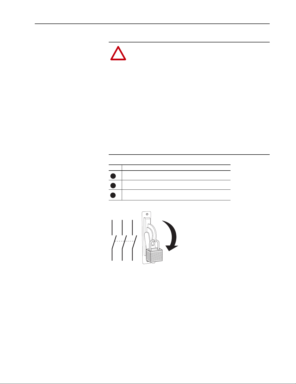
Task Description
Turn off and lock out input power. Wait five minutes.
A
Verify that there is no voltage at the drive’s input power terminals.
B
Measure the DC bus voltage at the +DC & -DC terminals on the
C
C
Power Terminal Block. The voltage must be zero.
L1 L2 L3
I
O
Page 4
4 Second Encoder Option Card for PowerFlex® 700S Drives with Phase II Control
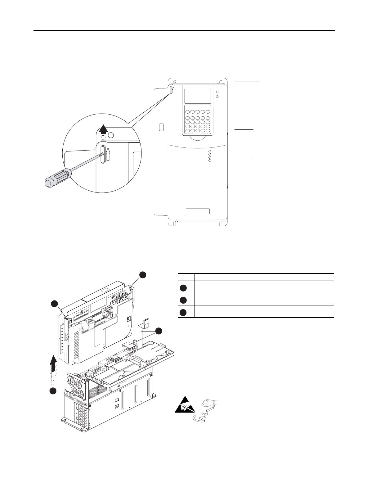
Step 2: Opening Door Over Power Structure and Main Control Board
Frames 1-4
Locate the slot in the upper left corner. Slide
the locking tab up and swing the cover open.
Special hinges allow cover to move away from
drive and lay on top of adjacent drive (if
present).
Frame 5
Slide the locking tab up, loosen the right-hand
cover screw and remove.
Frame 6
Loosen 2 screws at bottom of drive cover.
Carefully slide bottom cover down & out.
Loosen the 2 screws at top of cover and
remove.
Step 3: Removing the Control Cassette from Drive
B
BR1
B
R
2
D
C
+
D
C
-
PE
U/T1
V/T2
W/T3
R/L1
L2
C
B
A
Task Description
Disconnect the cables that connect to the main board
A
Loosen screws on face of cassette
B
Remove the cassette
C
C
=
Page 5

Step 4: Removing the Inside Cover from the Control Cassette
Task Description
Loosen screws on face of front cover and remove
A
the cover
Second Encoder Option Card for PowerFlex® 700S Drives with Phase II Control 5
Proper tightening torque for
reassembly is 7 to 10 lb.-in.
Step 5: Removing the Outside Covers from the Control Cassette
Task Description
Loosen screws on face of front cover and remove
A
the cover
Loosen screws on side of rear cover and remove
B
the cover
A
=
A
A
Proper tightening torque for
reassembly is 7-10 lb.-in.
A
=
B
Page 6

6 Second Encoder Option Card for PowerFlex® 700S Drives with Phase II Control
Step 6: Removing the Old Second Encoder Option Card and Stacker Connector
B
Skip this step if you are installing a new Second Encoder Option Card on a
drive that does not already have one.
Task Description
Disconnect the terminal block P1 from the Second Encoder Option Card
A
Remove three M3 screws (7-10 lb.- in.)
B
Carefully remove Second Encoder Option Card and Stacker connector
C
from the main control board
C
=
C
Important: Do not use a screwdriver to pry the P1 terminal plug from the
circuit board. This may damage the plug.
Step 7: Removing the Embedded EtherNet/IP Option Card
Skip this step if you are replacing a Second Encoder Option Card on a drive
that already has one.
If you are permanently removing the Second Encoder Option Card or are
performing the first installation of the Option Card you must remove the
EtherNet/IP Option Board (if present) to access the Two-Pin Jumper.
Task Description
Remove two screws which secure the Embedded
A
EtherNet/IP Option Board to the Main Board
Remove the Embedded EtherNet/IP Option Board
B
=
B
A
Proper tightening torque for
reassembly is 7-10 lb.- in.
Page 7

Step 8: Installing or Removing the Two-Pin Jumper
Second Encoder Option Card for PowerFlex® 700S Drives with Phase II Control 7
ATTENTION: If you fail to remove the Two-Pin Jumper before
installing the Stacker Connector, you may damage the main
!
control board. Make sure you remove the jumper before
installing the Stacker Connector.
Important: If you are permanently removing the Second Encoder Option
Card (running the drive without the option), you must install
the two-pin jumper. If you fail to install the jumper, the drive
will not run.
TIP: Save the jumper if you are installing the Option Card and removing
the jumper. You will need it if you remove the Option Card in the future.
Page 8

8 Second Encoder Option Card for PowerFlex® 700S Drives with Phase II Control
Step 9: Installing the Stacker Connector and Second Encoder Option Card
Task Description
A
B
C
D
ATTENTION: If you fail to remove the Two-Pin Jumper before
installing the Second Encoder Option Card, you may damage the
!
main control board. Make sure you remove the jumper before
installing the Stacker Connector.
Remove the terminal block P1 from the Second Encoder Option Card
It is much easier to remove before the card is installed
Plug the long pins of the Stacker connector into the Second Encoder
Option Card.
The end with the long pins must plug into the Option Card
Plug the Second Encoder Option Card and Stacker connector onto the
mating connector of the main control board.
The end with the short pins must plug into the main control board.
Install and tighten three M3 screws (7-10 lb.- in.)
B
The end with the long pins
must plug into the Option
=
D
Important: Do not use a screwdriver to pry the P1 terminal plug from the
circuit board. This may damage the plug.
Card.
C
Page 9

Second Encoder Option Card for PowerFlex® 700S Drives with Phase II Control 9
Step 10: Wiring and Configuring the Second Encoder Option Card
Terminal block P1 contains connection points for a differential encoder.
This terminal block resides on the Second Encoder Option Card.
Terminal Signal Description
1 N/C Not connected
2N/C
3N/C
4N/C
5 A Quadrature A input
6Not A
7 B Quadrature B input
8Not B
9Z Marker Pulse
10 Not Z
11 Power DC Power for encoder interface
12 Common
13 Shield Connection point for encoder
cable shield
Table A Recommended Cable
Cable Length Cable Description
less than or equal to 30m (98 ft.) Belden 9728 or equivalent 0.196 mm
shielded, twisted pairs
greater than or equal to 30m (98 ft.) Belden 9774 or equivalent 0.750 mm2 (18 AWG), individually
shielded, twisted pairs
2
(24 AWG), individually
Connection Examples
Differential Encoder with Internal Supply
A
Not A
B
Not B
Z
Not Z
Powe r
Common
Differential Encoder with External Supply
A
Not A
B
Not B
Z
Not Z
Powe r
Common
P1Encoder
1
2
3
4
5
6
7
8
9
10
11
12
13
P1Encoder
1
2
3
4
5
6
7
8
9
10
11
12
13
Powe r
Common
N/C
N/C
N/C
N/C
A
Not A
B
Not B
Z
Not Z
Powe r
Common
Shield
N/C
N/C
N/C
N/C
A
Not A
B
Not B
Z
Not Z
Powe r
Common
Shield
Page 10

10 Second Encoder Option Card for PowerFlex® 700S Drives with Phase II Control
Dip Switch Settings
Dip switch S1 configures the power supply output voltage and the encoder
interface input voltage. Almost all applications require you to set all four
switches on the assembly to either 5V dc or 12V dc.
Step 11: Replacing the Covers and Control Cassette
Voltage
Selection
5V dc Closed Closed Closed Closed
12V dc Open Open Open Open
The procedure for replacing the covers and control cassette is the reverse of
removing these components. Refer to Step 7: Removing the Embedded
EtherNet/IP Option Card on page 6, Step 5: Removing the Outside Covers
from the Control Cassette on page 5, Step 4: Removing the Inside Cover
from the Control Cassette on page 5 and Step 3: Removing the Control
Cassette from Drive on page 4.
SIDE VIEW
S1-1
(Supply)
S1
UP = OPEN = OFF
DOWN = CLOSED= ON
S1-2
(A Channel)
FRONT - TOP VIEW
OPEN
1
234
S1-3
(B Channel)
S1-4
(Z Channel)
Page 11

Second Encoder Option Card for PowerFlex® 700S Drives with Phase II Control 11
Step 12: Documenting Revision Changes
Document drive revisions on the “Field Installed Options” tag. Use the
blank line if you are installing the Second Encoder Option Card in a drive
that was manufactured without it.
FIELD INSTALLED OPTIONS
Firmware #: Date
#: Date
Firmware
20-HIM
HIM
28-IO-
I/O
20-COMM20B_-DB1-
COM Module
Internal Dynamic Brake
Specifications
TIP: Use packing material from new Second Encoder Option Card to
return the replaced Second Encoder Option Card
Consideration Description
Input Dual Channel Plus Marker, Isolated with differential transmitter Output
(Line Drive) Incremental, Dual Channel Quadrature type
Encoder Voltage Supply 5V dc or 12V dc 320 mA per channel
Maximum Input Frequency 400 kHz
Page 12

Publication 20D-IN009A-EN-P - August 2004 P/N 342528-P01
Copyright © 2004 Rockwell Automation. All rights reserved. Printed in USA.
 Loading...