

Page 1
Installation Instructions
Embedded EtherNet/IP Option Card for
DriveLogix
ATTENTION: To avoid an electric shock hazard, verify that the
voltage on the bus capacitors has discharged before performing
!
any work on the drive. Measure the DC bus voltage at the +DC &
–DC terminals of the Power Terminal Block (DC+ & DC- in high
power drives). The voltage must be zero.
ATTENTION: HOT surfaces can cause severe burns. Do not
touch the heatsink surface during operation of the drive. After
!
disconnecting power allow time for cooling.
ATTENTION: This drive contains ESD (Electrostatic
Discharge) sensitive parts and assemblies. Static control
!
precautions are required when installing, testing, servicing or
repairing this assembly. Component damage may result if ESD
control procedures are not followed. If you are not familiar with
static control procedures, reference A-B publication 8000-4.5.2,
“Guarding Against Electrostatic Damage” or any other
applicable ESD protection handbook.
™
5730 Controllers
What This Kit Contains
Tools That You Need
Verify that your kit contains the items listed in the following table. If your
kit does not contain the correct items, contact your Allen-Bradley sales
representative.
Quantity: Description
1 Embedded EtherNet/IP Option circuit board
2Screws
2 Stand-offs
• Phillips® screwdriver for M3 screws
• Standard (flat blade) screwdriver
Phillips® is a registered trademark of Phillips Screw Company
Page 2

2 Embedded EtherNet/IP Option Card for DriveLogix™5730 Controllers
What You Need to Do
To remove a Embedded EtherNet/IP Option Card from a PowerFlex 700S
drive:
❐ Step 1: Remove power from the drive
❐ Step 2: Open the main drive door
❐ Step 3: Remove the control cassette from the drive
❐ Step 4: Remove the inside cover from the control cassette
❐ Step 5: Remove the old Embedded EtherNet/IP Option Card from the
drive
To install a new Embedded EtherNet/IP Option Card onto a PowerFlex
700S drive:
❐ Step 6: Install the Embedded EtherNet/IP Option Card
❐ Step 7: Replace the covers and control cassette
❐ Step 8: Configure EtherNet/IP communications
❐ Step 9: Document revision changes
To return a replaced Embedded EtherNet/IP Option Card, use packing
material from the new Embedded EtherNet/IP Option Card.
Page 3
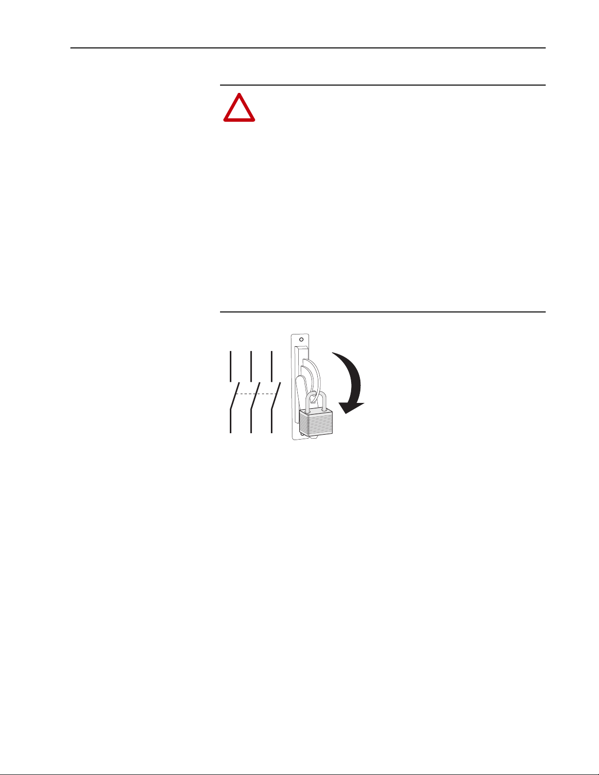
Step 1: Removing Power from the Drive
Embedded EtherNet/IP Option Card for DriveLogix™5730 Controllers 3
ATTENTION: To avoid an electric shock hazard, verify that the
voltage on the bus capacitors has discharged before performing
!
any work on the drive. Measure the DC bus voltage at the +DC &
–DC terminals of the Power Terminal Block. The voltage must
be zero.
Remove power before making or breaking cable connections.
When you remove or insert a cable connector with power
applied, an electrical arc may occur. An electrical arc can cause
personal injury or property damage by:
• sending an erroneous signal to your system’s field devices,
causing unintended machine motion
• causing an explosion in a hazardous environment
Electrical arcing causes excessive wear to contacts on both the
module and its mating connector. Worn contacts may create
electrical resistance.
L1 L2 L3
I
O
Page 4

4 Embedded EtherNet/IP Option Card for DriveLogix™5730 Controllers
Step 2: Opening Door Over Power Structure and Main Control Board
Frames 1-4
Locate the slot in the upper left corner. Slide
the locking tab up and swing the cover open.
Special hinges allow cover to move away from
drive and lay on top of adjacent drive (if
present).
Frame 5
Slide the locking tab up, loosen the right-hand
cover screw and remove.
Frame 6
Loosen 2 screws at bottom of drive cover.
Carefully slide bottom cover down & out.
Loosen the 2 screws at top of cover and
remove.
Step 3: Removing the Control Cassette from Drive
Proper tightening torque for
reassembly is 7 to 10 lb.-in.
B
BR1
B
R
2
D
C
+
D
C
-
PE
U/T1
V/T2
W/T3
R/L1
C
L2
Task Description
A
B
B
C
Disconnect the cables that connect to the main board
Loosen screws on face of cassette
Remove the cassette
A
=
Page 5

Step 4: Removing the Inside Cover from the Control Cassette
Task Description
Loosen screws on face of front cover and remove
A
the cover
Embedded EtherNet/IP Option Card for DriveLogix™5730 Controllers 5
Proper tightening torque for
reassembly is 7 to 10 lb.-in.
Step 5: Removing the Embedded EtherNet/IP Option Board
A
=
A
Task Description
Remove screws
A
Remove Embedded EtherNet/IP Option Board from
B
the Main Control Board
Remove standoffs
C
C
Do not perform this task if you are installing a new
Embedded EtherNet/IP Option Board
A
C
A
B
C
A
=
Page 6

6 Embedded EtherNet/IP Option Card for DriveLogix™5730 Controllers
Step 6: Installing the Embedded EtherNet/IP Option Board
B
A
C
D
Task Description
Install and tighten standoffs (7 to 10 lb.-in.)
A
Align connector on Embedded EtherNet/IP Option
B
Board with connector on Main Control Board
Place Embedded EtherNet/IP Option Board on the
C
C
Main Control Board
Install and tighten screws (7 to 10 lb.-in.)
D
=
Step 7: Replacing the Covers and Control Cassette
Step 8: Configuring EtherNet/IP Communication
A
D
The procedure for replacing the covers and control cassette is the reverse of
removing these components. Refer to Step 4: Removing the Inside Cover
from the Control Cassette on page 5, Step 3: Removing the Control Cassette
from Drive on page 4 and Step 2: Opening Door Over Power Structure and
Main Control Board on page 4.
Referring to publication 20D-UM003… , User Manual - DriveLogix5730
Controller, configure the EtherNet/IP port on the option card.
Page 7

Embedded EtherNet/IP Option Card for DriveLogix™5730 Controllers 7
Step 9: Documenting Revision Changes
Document drive revisions on the “Field Installed Options” tag. Use the
blank line if you are installing the Embedded EtherNet/IP Option Board in a
drive that was manufactured without it.
FIELD INSTALLED OPTIONS
Firmware #: Date
#: Date
Firmware
20-HIM
HIM
28-IO-
I/O
20-COMM20B_-DB1-
COM Module
Internal Dynamic Brake
TIP: Use packing material from new Embedded EtherNet/IP Option Board
to return the replaced Embedded EtherNet/IP Option Board
Page 8

Publication 20D-IN012A-EN-P - July 2004 P/N 342545-P01
Copyright © 2004 Rockwell Automation. All rights reserved. Printed in USA.
 Loading...