

Page 1

Programming Manual
Logix5000 Controllers Import/Export Project Components
Catalog Numbers 1768-L43, 1768-L45
Page 2
Important user information
Read this document and the documents listed in the additional resources section about installation, configuration, and operation of
this equipment before you install, configure, operate, or maintain this product. Users are required to familiarize themselves with
installation and wiring instructions in addition to requirements of all applicable codes, laws, and standards.
Activities including installation, adjustments, putting into service, use, assembly, disassembly, and maintenance are required to be
carried out by suitably trained personnel in accordance with applicable code of practice. If this equipment is used in a manner not
specified by the manufacturer, the protection provided by the equipment may be impaired.
In no event will Rockwell Automation, Inc. be responsible or liable for indirect or consequential damages resulting from the use or
application of this equipment.
The examples and diagrams in this manual are included solely for illustrative purposes. Because of the many variables and
requirements associated with any particular installation, Rockwell Automation, Inc. cannot assume responsibility or liability for
actual use based on the examples and diagrams.
No patent liability is assumed by Rockwell Automation, Inc. with respect to use of information, circuits, equipment, or software
described in this manual.
Reproduction of the contents of this manual, in whole or in part, without written permission of Rockwell Automation, Inc., is
prohibited.
Throughout this manual, when necessary, we use notes to make you aware of safety considerations.
WARNING: Identifies information about practices or circumstances that can cause an explosion in a hazardous environment, which may lead to
personal injury or death, property damage, or economic loss.
ATTENTION: Identifies information about practices or circumstances that can lead to personal injury or death, property damage, or economic
loss. Attentions help you identify a hazard, avoid a hazard, and recognize the consequence
Important:
Identifies information that is critical for successful application and understanding of the product.
Labels may also be on or inside the equipment to provide specific precautions.
SHOCK HAZARD: Labels may be on or inside the equipment, for example, a drive or motor, to alert people that dangerous voltage may be
present.
BURN HAZARD: Labels may be on or inside the equipment, for example, a drive or motor, to alert people that surfaces may reach dangerous
temperatures.
ARC FLASH HAZARD: Labels may be on or inside the equipment, for example, a motor control center, to alert people to potential Arc Flash. Arc
Flash will cause severe injury or death. Wear proper Personal Protective Equipment (PPE). Follow ALL Regulatory requirements for safe work
practices and for Personal Protective Equipment (PPE).
Allen-Bradley, Rockwell Software, Rockwell Au tomation, and TechConnect are trademarks of Rockwell Automation, Inc.
Trademarks not belonging to Rockwell Automation are prope rty of their respective companies.
Page 3
Summary of changes
This manual contains new and updated information. This table contains the
changes made to this revision.
Topic Page
Introduction: Added a description of Library Management. See Introduction on page 9.
Export Components: Updated procedure to explain the
difference between exporting programs from the Logical
Organizer versus the Controller Organizer.
Export Considerations: Added a bullet to explain the difference
between exporting programs from the Logical Organizer versus
the Controller Organizer.
Configure Component Import: Updated dialog box graphic. See Properties for imported components on page
Configure Multiple Components: Added new section to describe
importing multiple components.
Online Import Considerations: Added explanation for new
'Preserve existing tag values in offline project checkbox.
Multiple Components Considerations: Added considerations for
importing multiple components.
Search and Replace: Updated procedure to explain the new
Replace All option.
Equipment Phases: Added new import considerations. See Import considerations on page 43.
Tags: Added new import considerations. See Import considerations on page 43.
See Export logic components on page 11.
See Export logic components on page 11.
16.
See Configure multiple component properties on
page 21.
See Online import on page 12.
See Multiple components on page 15.
See Find and replace on page 35.
Rockwell Automation Publication 1756-PM019E-EN-E - October 2014 3
Page 4

Page 5

Preface
Import and export logic
Additional considerations for
Additional considerations for
Table of contents
components
Studio 5000 environment ..................................................................................... 7
Chapter 1
Introduction ............................................................................................................ 9
Export considerations .......................................................................................... 10
Export logic components..................................................................................... 11
Import considerations .......................................................................................... 12
Online import ................................................................................................ 12
Motion ............................................................................................................. 14
Safety ................................................................................................................ 15
Security ............................................................................................................ 15
Multiple components ................................................................................... 15
Import logic components .................................................................................... 15
Configuration properties for import ................................................................. 16
Properties for imported components ......................................................... 16
Configure multiple component properties ............................................... 21
Configure program connections ................................................................. 24
Configure component references ............................................................... 29
References configuration example .............................................................. 31
Undefined references .................................................................................... 32
Attention flags ................................................................................................ 33
Errors and warnings on import ................................................................... 33
Project documentation ........................................................................................ 33
Find and replace .................................................................................................... 35
compatibility .................................................................................................. 36
rungs
routines
Rockwell Automation Publication 1756-PM019E -EN-E - October 2014 5
Chapter 2
Introduction .......................................................................................................... 39
Export considerations .......................................................................................... 39
Import considerations .......................................................................................... 39
Chapter 3
Introduction .......................................................................................................... 41
Export considerations .......................................................................................... 41
Import considerations .......................................................................................... 41
Page 6

Table of Contents
Additional considerations for
Additional considerations for
Import and export Add-On
Additional considerations for
Index
programs and equipment
phases
user-defined types
Instructions
Chapter 4
Introduction .......................................................................................................... 43
Export considerations .......................................................................................... 43
Import considerations .......................................................................................... 43
Chapter 5
Introduction .......................................................................................................... 45
Export considerations .......................................................................................... 45
Import considerations .......................................................................................... 45
Chapter 6
Introduction .......................................................................................................... 47
Create export files ................................................................................................. 47
Export to separate files .................................................................................. 48
Export to one file ........................................................................................... 49
Import an Add-On Instruction ......................................................................... 50
Import considerations .................................................................................. 50
Import configuration .................................................................................... 52
Update an Add-On Instruction to a later revision using import ................. 53
tags
6 Rockwell Automation Publication 1756-PM019E-EN-E - October 2014
Chapter 7
Introduction .......................................................................................................... 57
Export considerations .......................................................................................... 57
Import considerations .......................................................................................... 57
Page 7
Studio 5000 environment
Preface
Use this manual to become familiar with importing and exporting project
components for Logix5000 controllers. The project components covered in this
manual include the importing and exporting of rungs, routines, programs and
equipment phases, user-defined types, tags, and Add-On Instructions.
This manual is one of a set of related manuals that show common procedures for
programming and operating Logix5000 controllers.
For a complete list of common procedures manuals, see the
Common Procedures Programming Manual, publication 1756-PM001.
The term Logix5000 controller refers to any controller that is based on the
Logix5000 operating system.
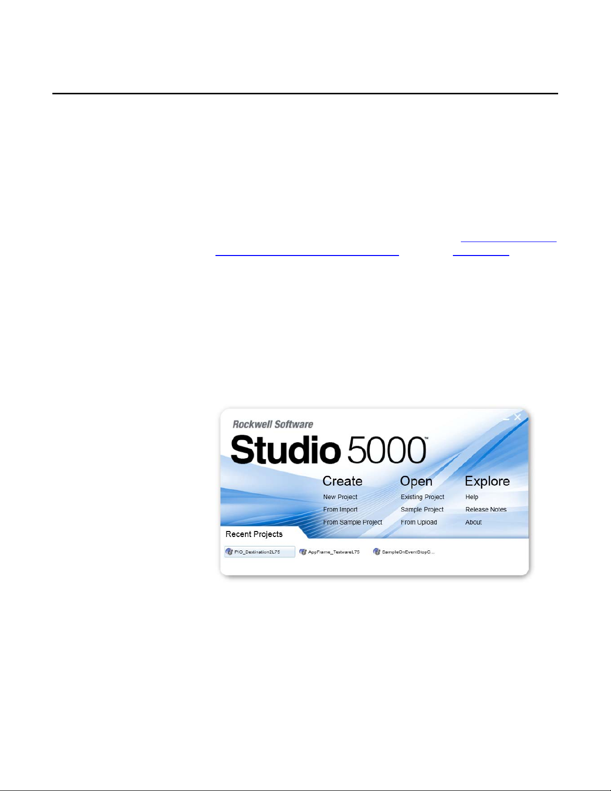
The Studio 5000 Automation Engineering & Design Environment™ combines
engineering and design elements into a common environment. The first element is
the Studio 5000 Logix Designer™ application. The Logix Designer application is
the rebranding of RSLogix™ 5000 software and will continue to be the product to
program Logix5000™ controllers for discrete, process, batch, motion, safety, and
drive-based solutions.
Logix5000 Controllers
Rockwell Automation Publication 1756-PM019E -EN-E - October 2014 7
The Studio 5000® environment is the foundation for the future of
Rockwell Automation® engineering design tools and capabilities. The Studio 5000
environment is the one place for design engineers to develop all elements of their
control system.
Page 8

Page 9

Introduction
Chapter 1
Import and export logic components
This chapter explains import and export of logic components.
You use the Logix Designer application to perform online edits for the Logix
family of controllers.
The import/export functionality provides a greater degree of flexibility during
development and deployment of projects. It supports the ability to export a
component of a Logix Designer project and then import that component into
either the same, or a different project, offline or online (even in Remote Run
mode). It lets you import components to create something new in a project, or to
update something that exists.
You can export and import these logic components offline and online:
• Rungs
• Routines
• Programs and equipment phases
• User-defined data types (UDT)/user-defined string types
• Add-On Instructions
• Trends
Changes or additions to a project that may be impractical to do with online
editing can be completed offline and then imported in one operation into a
running controller by using the extended import/export feature. Engineering
collaboration is also facilitated because many engineers can work on one or more
of the project components independently offline and then use import to merge the
changes into one project.
With online editing, you modify or create a component and then modify other
components referenced by that component in the project sequentially. Importing
online differs from online edits in that it provides the ability to create and delete
components, as well as update referenced components, in one step.
Rockwell Automation Publication 1756-PM019E -EN-E - October 2014 9
ATTENTION: All Rockwell Automation XML files are encoded in UTF-8 file format. Users editing XML files
must use a text editor like Notepad that supports UTF-8 encoding. If you save the edited file by using a nonUTF-8 compatible editor after making changes, the encoding breaks, resulting in a non-valid XML file.
Page 10
Chapter 1 Import and export logic components
Export considerations
Keep the following considerations in mind when exporting components.
• You may get more than you expected in an .l5x file. Some components
referenced by the exported component are also exported.
• Starting with version 24 of Logix Designer, you can use program parameters
to share data directly between programs in addition to Controller-scoped
tags. For more information on program parameters, see the
Logix5000
Controllers Program Parameters Programming Manual publication 1756PM021.
When exporting a
Set of rungs Rungs Controller-scoped tags, program-scoped tags,
Routine Routine Controller-scoped tags, program-scoped tags,
Program
(For considerations when
exporting multiple
programs using multi-
Multiple
select, see
components on page 15.
Equipment Phase Equipment phase, routines, phase-
User-defined data type User-defined data type User-defined data types, user-defined string
User-defined string type User-defined string type
Add-On Instruction Add-On Instruction, Logic routine and
Trend Trend
The exported component includes
the
Program, routines, and program-scoped
tags
scoped tags, and controller-scoped
PHASE tag
any scan mode routines, and parameter
and local tags
The exported file also includes referenced
user-defined data types, user-defined string
types, Add-On Instructions
user-defined data types, user-defined string
types, Add-On Instructions
Controller-scoped tags, user-defined data types,
user-defined string types, Add-On Instructions
When you export a program from the Logical
Organizer, the program logical hierarchy is
exported in addition to the program specified.
See the online help for information about the
Logical Organizer.
Controller-scoped tags, user-defined data types,
user-defined string types, Add-On Instructions
types, Add-On Instructions
User-defined data types, user-defined string
types, Add-On Instructions
10 Rockwell Automation Publication 1756-PM019E -EN-E - October 2014
For example, if you export a rung with an instruction that uses (references) a
bit in a tag that is a user-defined type tag, the export content includes the
referenced tag and the referenced user-defined type, along with the rungs.
When you import the rung, you can choose whether to also import the
referenced tag and user-defined type.
Page 11
Import and export logic components Chapter 1
Export logic components
• Only the offline data values of tags are exported to the .l5x file, even when
the project is online with the controller. When exporting components that
include tags while online, the software prompts you to upload tag values
before exporting the component.
Important:
Whether exporting while offline or online with the controller, only offline data values of tags
are exported to the .l5x file.
• You can export a component that has Test Edits, but the resulting file
cannot be imported. If an .l5x file with Test Edits is selected for import,
then the import aborts.
Follow these steps to export logic components.
1. In the Logix Designer Controller Organizer, select the logic component to
export.
Tip:
Tip:
You can select multiple programs, Add-On Instructions, and user-defined data types for export. See
Import and export Add-On Instructions on page 49 for detailed information.
You can also export logical components from the Logical Organizer, where you can select multiple
programs and include child folders and programs in their hierarchical levels. See the Logix Designer
application online he lp for instructions.
2. Right-click and select Export <logic component> as explained in the
following table.
To export a Choose
Set of rungs (For rung export, select the rungs in the
ladder routine editor.)
Routine
Program
Equipment Phase
User-defined data type
User-defined string type
Add-On Instruction
Trend
Export Rungs
Export Routine
Export Program
Export Equipment Phase
Export Data Type
Export Data Type
Export Add-On Instruction
Export Trend
3. In the File Name box, type a file name for the export file.
Tip:
You can export multiple Add-On Instructions to a single file or to multiple files. See
component properties on page 21 for detailed information.
Configure multiple
Rockwell Automation Publication 1756-PM019E -EN-E - October 2014 11
Page 12
Chapter 1 Import and export logic components
The timeout is caused by the (scan time) x (number of changed rungs). You could have a large program with
Import considerations
4. (Optional) In the File description, edit the default description or type a
description, if desired.
A default description is supplied for some component exports.
Tip:
The file description can be viewed in a tooltip during import when selecting which file to import.
5. Click Export.
This section covers general considerations for all component-type imports. See the
chapters for specific components (program, routine, rungs, Add-On Instructions,
user-defined data types, and tags) for additional export and import considerations
for that component, whether it is imported directly or as a reference during
another component import.
Important:
Tip:
When editing online, if the program scan time is large, or the number of modified rungs is large, you might
see HMI and Logix Designer communication timeouts when edits are finalized.
a very fast scan, or a lot of rungs (but you modified only a few), and you do not see a timeout.
Starting with version 24 of Logix Designer application, you can use program parameters to share data between
programs in much the same way that you use controller-scoped tags. Program parameters are imported and
exported in the same way as tags in most instances. For more information on program parameters, see the
Logix5000 Controllers Program Parameters Programming Manual, publication 1756-PM021
.
Online Import
Topic Consideration
Tag data values When overwriting tags while online, data values are not written to the online project. Data
values for overwritten tags while online are written only to the offline project.
Data values for tags created while online are written to the offline and online project.
Select the Preserve existing tag values in offline project check box to prevent tag values
from being overwritten in the offline project.
Locking controller edits When performing an online import, the controller is locked, preventing other workstations
connected to the controller from making edits until the import completes. If another
workstation has the controller locked, an online import cannot be initiated.
Tag attributes
12 Rockwell Automation Publication 1756-PM019E -EN-E - October 2014
Tag attributes (for example, External Access, Constant, and Style) are written to the online
project and the offline project.
If existing tags are to be overwritten with new attributes that are incompatible with existing
user logic, the import is not allowed.
Page 13
Import and export logic components Chapter 1
program, or routine properties that are modified are downloaded immediately. These changes
Topic Consideration
Online options When importing programs, equipment phases, routines, or rungs online, the logic can be
imported as:
• Pending Edits that exist only in the offline project and are not downloaded to the
controller.
• Accepted Edits that are downloaded to the controller where they can be tested, accepted,
or canceled.
• Finalized Edits that are downloaded to the controller, assembled, and cannot be canceled.
As with normal online editing, with any online option chosen, any tags, data types, or Add-On
Instructions that are created or modified are downloaded immediately. In addition, any task,
remain in the controller, even if logic edits are later canceled. Pending Edits and Accepted
Edits options do not apply to Add-On Instructions and user-defined types, so Online Options
are not presented during an Add-On Instruction or user-defined type import.
Under the following conditions, only the Finalize All Edits in Program option is available.
• When you are online with t he controller and you import a program that contains
connections to InOut parameters and:
− You change the final connection of an InOut parameter online.
• When the connections are different than what is currently downloaded to the controller.
Finalize All Edits In Program is your only option because you chose to overwrite the
program on Import. You must configure the InOut connections such that the InOut
parameter connection is taken not from the destination controller but from the Import file,
or from a new final name for the connection entered by the user.
• When you import a program or programs with connections online and in Remote Run
mode, and:
− A connection is changed from connect to disconnect.
− A connection is changed from disconnect to connect.
− The final name of a connection is changed.
− A connection is added and its operation is set to connect.
• When you import program hierarchies or multiple programs online and in Remote Run
mode.
External access If the External Access is changed, it may change the behavior of your running HMI.
Changed External Access attributes for overwritten tags can cause changes to HMI behavior,
regardless of whether logic changes are tested, accepted, or finalized.
Rockwell Automation Publication 1756-PM019E -EN-E - October 2014 13
Page 14
Chapter 1 Import and export logic components
ne (choosing Finalize Edits) does not cause the communication timeout,
Topic Consideration
Asynchronous import Import operations are not synchronized with the Program Scan (just as online editing
operations are not synchronized). For most objects, this does not matter because:
• Existing online tag data values are never overwritten.
• New tags and their initial data values are written to the controller before the new logic
runs.
• The switch-over to the new logic is synchronized with the program scan (just like online
editing).
In general, although online tag data values are not overwritten, some object attributes can
change asynchronously to the Program Scan. Some examples:
• Changed attributes of existing programs or equipment phases (such as changing the Initial
Step Index of an equipment phase) are written to the controller before switch-over, so old
logic can run with the new configuration.
• An existing program without a main routine could become configured with a main routine
as part of import, and that main routine runs immediately even though the new logic for
that routine has not yet been accepted.
• Changing Logix-based alarm tag configuration (such as alarm messages or associated tag
definitions) can go into effect while the old alarm trigger logic is still active, resulting in
alarm messages that do not match the condition.
Communication timeouts Communication timeouts may occur when rungs are deleted online in Run mode if the
program scan time is long or the number of rungs being deleted is large.
If you use Partial Import Online and choose Pending or Accept edits, when you later Finalize
those edits, a timeout can occur. This timeout can occur as HMI or Logix Designer
communication timeouts. Keep the following timing considerations in mind.
• Finalizing online edits while in Run mode causes brief interruptions to communication,
which are usually unnoticeable.
• The length of the communication interruption is related to the product of the (task scan
time) x (the number of changed rungs).
• When very long program scans or large quantities of changed rungs occur, the
communication interruption can be long enough to cause timeouts.
• The timeout of a Rockwell Automation HMI is typically 8 seconds, while a Logix Designer
online session typically has a 30-second timeout.
• It does not matter whether the edits came from individual online edits or from a Partial
Import Online (choosing Pending or Accepted edits).
• Partial Import Onli
due to the use of asynchronous transaction commit processing.
Motion
Topic Consideration
Motion components
limitations while online
14 Rockwell Automation Publication 1756-PM019E -EN-E - October 2014
Motion tags (Axis, Coordinate System, and Motion Group) cannot be created, modified or
deleted during an online import, however, existing motion tags can be referenced. When
doing an offline import, motion tags can be created and modified.
Page 15
Import and export logic components Chapter 1
Import logic components
Safety
Topic Consideration
Safety components
limitations while online
Safety components
limitations while offline
Scheduled location In a Safety project, Safety programs cannot be imported into a Standard task and vice
Safety programs imported
into a standard project
Controller Fault Handler and
Power-Up Handler
Safety components cannot be created, modified or deleted during an online import.
Safety components cannot be created, modified or deleted during an offline import. If a
Safety Signature exists, the project is Safety locked. A non-recoverable safety fault is
present if the Safety Partnership status between the primary controller and the safety
partner is any value other than ‘OK’, or if Safety modify permissions are denied.
versa.
Safety programs imported into a Standard project are converted to Standard programs
during the import processing and a warning appears in the Errors/Results Pane during
initial parsing of the .l5x file. In this case, imported logic does not verify after import if it
contains instructions that are only valid in a Safety routine.
A Safety program cannot be scheduled in the Controller Fault Handler or Power-Up
Handler folders.
Security
Topic Consideration
Project is secured If the project is secured, the import process may not be able to create, delete, or modify some
components, depending on the security actions that have been granted or denied for those
components.
Multiple components
Topic Consideration
Importing multiple Userdefined types (UDTs) and
Add-On Instructions.
Controller Fault Handler and
Power-Up Handler disabled
Follow these steps to import logic components. You can import components from
the Controller Organizer and from the Logical Organizer.
When User-defined types (UDTs) and Add-On Instructions are imported using the Multiple
Components option, all UDTs and Add-On Instructions are treated as references. Unlike
child components, referenced components can be configured independently from the
import target.
When you import multiple target programs, the Controller Fault Handler and Power-Up
Handler are unavailable in the Schedule In list.
Rockwell Automation Publication 1756-PM019E -EN-E - October 2014 15
Importing components into a controller while online can affect controller operation. Use caution when
modifying logic while online in Remote Run or Run mo de.
1. Right-click the item and choose the import component menu item as
described in the following table.
Page 16
Chapter 1 Import and export logic components
Configuration properties
To import a Right-click And choose
Set of rungs A rung or set of rungs within a Ladder routine
editor
Routine A program or equipment phase
Program A task, the Controller Fault Handler folder, the
Power-Up Handler folder, or the Unscheduled
Programs/Phases folder
Equipment Phase A task or the Unscheduled Programs/Phases folder
Import Rungs
Import Routine
Import Program
Import Equipment Phase
for import
User-defined data type User-Defined folder
User-defined string type Strings folder
Add-On Instruction Add-On Instructions folder
Trend Trends folder
Import Data Type
Import String Type
Import Add-On Instruction
Import Trend
2. Select the file to import.
You can select multiple components for import. See
Configure multiple
component properties on page 21 for information.
3. Click Import.
4. Continue by selecting the configuration options described in Configuration
properties for import.
This section describes configuration options for importing components.
Tip:
Trends do not require any import configuration, so the Import Configuration dialog box does not appear and
the trend is imported immediately.
16 Rockwell Automation Publication 1756-PM019E -EN-E - October 2014
Properties for imported components
When you import components, the previously exported information is brought
into the project based on the import configuration you select. You determine how
the imported component (a program, for example) connects to the existing project
either by overwriting an existing component of the same type, or by creating a new
one.
Page 17
Import and export logic components Chapter 1
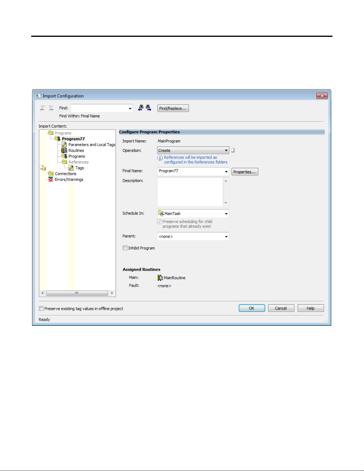
The following screen capture shows a typical Import Configuration dialog box.
Your dialog box might contain options different than those shown here,
depending on the component you import.
An import component collides with an existing component if a component of the
same type, scope, and with the same name exists in the project. By configuring the
Final Name of the imported component, you determine whether the imported
component collides with an existing component, or it does not (if a component of
the same type, scope and with the same name does not exist in the project). For a
collision, you can use the existing project component or you can overwrite it. For a
non-collision, you can create a project component or you can discard, and not
import, the component from the import file. In any case, any imported logic
references are updated to be the same as the Final Name.
By configuring the Operation for the component, you determine whether it is
imported from the file or an existing component is used. Incompatibility of a
Rockwell Automation Publication 1756-PM019E -EN-E - October 2014 17
Page 18
Chapter 1 Import and export logic components
collision or other situations, for example, project security privileges, may affect
what Operations are permitted for a component.
The following table describes the configuration options.
Configuration Description
Import Name
Operation
Final Name
Description
The Import Name is read-only and shows the name of the component as read from the
import file.
The Operation determines whether the component from the import file is imported. Not
all operations are applicable to a given component in all situations. Sometimes there is
only one possible operation permitted in a particular situation.
Choose from these options:
• Use Existing (collisions) to use the existing component in the project. The component
definition in the import file is not imported. If the component collides and there is no
definition for the component in the import file, then this is the only Operation
available.
• Overwrite (collisions) to import the component definition from the import file and
overwrite the existing component definition in the project.
Important: If you select Overwrite for a reference tag, the tag data that is different is
written to the offline project only, even if you are online with the controller.
• Create (non-collisions) to import the component from the import file creating a new
component in the project.
• Discard (non-collisions) to discard the component and abort import. If the main
component from the import file (the program during a program import, for example) is
discarded, the references can still be imported. If a referenced component is discarded,
any imported logic references are not defined in the project and might not verify after
impor t.
• Undefined (non-collision) is the only Operation available if the component does not
collide and there is no definition for the component in the import file. The imported
logic is not verified after import.
• Delete (non-collision) indicates that this component will be deleted from the project
on import.
The Final Name determines the name of the component that shows in the project after
the import (except in the case of a Delete Operation).
You can create or avoid collisions by changing the Final Name. If you change the Final
Name to differ from the Import Name, all logic references in the import content are
updated.
If you change the Final Name of a component during configuration so that it collides with a
different existing component after it was colliding with another, any changes you made to
the Operation are preserved.
The Description shown depends on the Operation. If the Operation is:
• Overwrite or Create, the description is initially the description from the import file.
You can edit it during import configuration.
• Discard, the description is initially the description from the import file. It is read-only
and may not be edited.
• Use Existing or Delete, the description is the existing component description. It is
read-only and may not be edited.
• Undefined, no description is shown.
The description for members of an expanded tag follow the same rule the tag follows. Only
members of the tag that have descriptions are shown when the tag is expanded.
18 Rockwell Automation Publication 1756-PM019E -EN-E - October 2014
Page 19
Import and export logic components Chapter 1
Configuration Description
Schedule In
Preserve scheduling for child
programs that already exist
The Schedule In setting determines the task in which the imported component is
scheduled.
The default setting for Schedule In depends on the Operation setting and whether you
import the component into the Controller Organizer or the Logical Organizer.
If you import the component into the Controller Organizer:
• When you select a task or handler, and Operation is set to Overwrite, Schedule In is
set to the selected task or handler.
• When you select a task or handler and Operation is set to Use Existing, Schedule In
is set to the task or handler where the program is scheduled in the destination project.
• When the selection in Controller Organizer is not a task or handler, Schedule In is set
to Unscheduled Programs/Phases.
If you import the component into the Logical Organizer:
• When you set Operation to Create or Disca rd, Schedule In is set to Unscheduled
Programs/Phases.
• When you set Operation to Use Existing or Overwrite, Schedule In is set to the Task
or Handler for which the program is scheduled in the destination project.
You can adjust the S chedule In setting when:
• Operation is set to Create (the target component is being created).
• Operation is set to Overwrite and you are not online in Remote Run mode.
You cannot change the Schedule In setting when:
• You import a program folder.
• Operation is set to any setting other than Create or Overwrite.
When you select this setting, any child programs that exist in the destination project
remain scheduled as configured in the project. When you clear this setting, all imported
programs are scheduled in the task specified by the Schedule In setting.
This setting is available when Operation is set to Create or Overwrite; otherwise it is
read-only. When enabled, this setting is selected by default. The setting is not preserved
between import sessions.
Rockwell Automation Publication 1756-PM019E -EN-E - October 2014 19
Page 20

Chapter 1 Import and export logic components
Configuration Description
Parent Determines where the imported component is organized.
The default setting for Parent depends on whether you exported the component from the
Controller Organizer or the Logical Organizer, whether you are importing it to the
Controller Organizer or the Logical Organizer, and on the Operation setting.
• If you exported the program from the Controller Organizer and you are importing it to
either the Controller Organizer or the Logical Organizer:
− Parent is set to the selected program in the Logical Organizer if the operation is
Create or Discard.
− Parent is set to the parent configured in the destination project if Operation is set
to Use Existing or Overwrite.
• If you exported the program from the Logical Organizer and you are importing it to the
Logical Organizer:
− Parent is set to the selected program in the Logical Organizer if Operation is set to
Create or Discard.
− Parent is set to the parent configured in the destination project if Operation is set to
Use Existing.
− Parent is set to the selected item in the Logical Organizer if Operation is set to
Overwrite.
• If you exported the program from the Logical Organizer and you are importing it to the
Controller Organizer:
− Parent is set to <none> if Operation is set to Create, Discard, or Overwrite.
− Parent is set to the parent configured in the destination project if Operation is set
to Use Existing.
When there is a collision, the components colliding may be identical, or they may
be different. If they are the same, the Operation defaults to Use Existing. If they
are different, imported components default to Overwrite while referenced
components default to Use Existing. Choose Overwrite to use the component
definition from the import file, or Use Existing to use the component in the
project. Icons on the Import Configuration dialog box (next to the Operation
control) show whether colliding components are identical or different.
Situation Icon
Component shows only in the import file (non-collision)
Component shows only in the project (non-collision)
Component collides with a component in the project and differences exist
Component collides with a component in the project and they are identical No icon
To see the differences between the import component and the colliding project
component, click Collision Details and a dialog box opens. Use the information
in the dialog box to determine whether to overwrite or to use the existing
component.
20 Rockwell Automation Publication 1756-PM019E -EN-E - October 2014
Page 21

Import and export logic components Chapter 1
For components that do not collide, click Properties for more information on the
component.
Important:
A component you select for import that collides with an existing component defaults to overwriting the
project component unless the components are identical, in which case, the project component is used. If the
project component is used, references may still be imported.
Configure multiple component properties
This section describes the settings you use to import and configure multiple
components.
You carry out multiple steps when you import components.
• First, you select components for export from a project.
• You export those components.
• You select those components and import them into another project.
Use one of the following methods to import multiple components.
• Select Import Component from the File menu and choose the component
type that you want to import.
• Copy the programs, Add-On Instructions, or UDTs, right-click a task in
the organizer, and click Paste With Configuration on the menu.
Note:
The Paste With Configuration menu option works when copying from the Controller Organizer to the Logical Organizer,
and vice versa.
Rockwell Automation Publication 1756-PM019E -EN-E - October 2014 21
Page 22

Chapter 1 Import and export logic components
The following screen capture shows a typical Import Configuration dialog box
for multiple components. Your dialog box might contain options different than
those shown here, depending on the components you import.
Imported items are listed in the Import Content pane based on the items that are
part of the import content.
22 Rockwell Automation Publication 1756-PM019E -EN-E - October 2014
Page 23

Import and export logic components Chapter 1
• Programs -- If you are importing multiple programs, the grid shows the
programs that are being imported into the project. If you are importing
multiple hierarchies, the grid shows the programs and the children of the
programs that are being imported into the project.
• Tags, Add-On Instructions, Data Types and Other Components --
References include any tags directly referenced by any imported logic or tags
(using Alias For).
• Connections -- Lists the connections, from programs that are external to
the programs in the import content, that are also connected to programs in
the existing project.
The following table describes the multiple-import configuration parameters.
Configuration Description
Multiple Programs
Imported Programs Shows the number of parent and child programs (if applicable) that are being imported
Operation Identifies what is done with the programs upon import.
Schedule In Shows the task in which the imported programs are scheduled.
Do not change scheduling of
existing programs
The Import Content pane shows the number of programs that are being imported into
the project.
The value shown in the parenthesis excludes children of the programs.
If differences occur among the programs, the difference icon appears in the Differences
column of the Programs grid.
into the project.
• If Import is selected, all programs are imported into the project.
• If Discard is selected, the programs are not imported into the project.
The box is set to Import by default. However, you can choose Discard from the menu.
Note: To see the Operation value for a specific program, check the Programs grid of the
program's child program.
The default value for the Schedule In value is the selected task or Unscheduled
Programs/Phases based on which method you use to import the content, and from which
organizer you initiate the import.
• If you use Paste Special>With Configuration in the Controller Organizer, the
default value is the selected task.
• If you use the Paste Special>With Configuration option or the File>Import
Component option in the Logical Organizer, the default value is Unscheduled
Programs/Phases.
The Operation box must be set to Import to modify the Scheduled In value.
When selected, programs that exist in the project remain scheduled as they are configured
in the project. The check box is selected by default.
When cleared, upon import, programs are scheduled in the task specified in the Schedule
In box.
To modify this option:
• The Operation box must be set to Import.
• The controller cannot be in Remote Run mode.
Rockwell Automation Publication 1756-PM019E -EN-E - October 2014 23
Page 24
Chapter 1 Import and export logic components
Logical Organizer, or when you are importing programs into the Controller Organizer. If
Configuration Description
Parent Specifies how the programs are organized upon import.
• When you import a program into the Logical Organizer, the default is the Parent in the
selected program in the Logical Organizer.
• The default is <none> when a Parent is not specified in the selected program in the
a Parent is not specified, the programs remain organized as they are configured in the
project.
The Operation box must be set to Import to modify the Parent option.
Do not change parent of
existing programs
Select this check box and programs that exist in the project remain organized as they are
configured in the project. The check box is selected by default.
Clear this check box and upon import, programs are organized in the program that is
specified in the Parent box.
All child programs are imported as organized in the import content regardless if the check
box is selected or cleared.
The Operation box must be set to Import to modify this option.
Configure program connections
When you import a program, you might need to configure connections to
program parameters or controller scope tags that exist in the project. You can
configure connections when you select the target program on the Import
Configuration dialog box and Operation is set to Overwrite or Create. If
Operation is set to Use Existing or Discard, the Connections grid does not
appear.
When you import multiple programs, any connections between the programs you
are importing cannot be configured, and do not appear in the Connections grid.
However, any connections with endpoints outside these programs do appear and
may be configured.
Logix Designer application imports the connection endpoints, and they remain
what they were in the original project. If the endpoints exist in the destination
project, they bind automatically. If the endpoints do not exist, they are flagged as
errors and you must change the Final Connection name to bind them to the
correct connections, or remove the connections.
The following diagrams describe how imported connections are established.
24 Rockwell Automation Publication 1756-PM019E -EN-E - October 2014
Page 25

Import and export logic components Chapter 1
In My Original Project, the parameters in Program1 are connected to parameters
in Program2.
When you import the original Program1 into My New Project, the parameters in
Program1 connect automatically to matching parameters in Program2. Parameters
that do not match are flagged as errors. You need to change the Final Connector
for those parameters.
If the endpoint names are different in My New Project (for example, Program3)
you can either open the Connections grid and change the Final Connection
name on the endpoints from Program2 to Program3, or you can go to the
References grid and change the final name on Program2 to Program3 in one place,
and all the connections change automatically.
Rockwell Automation Publication 1756-PM019E -EN-E - October 2014 25
Page 26
Chapter 1 Import and export logic components
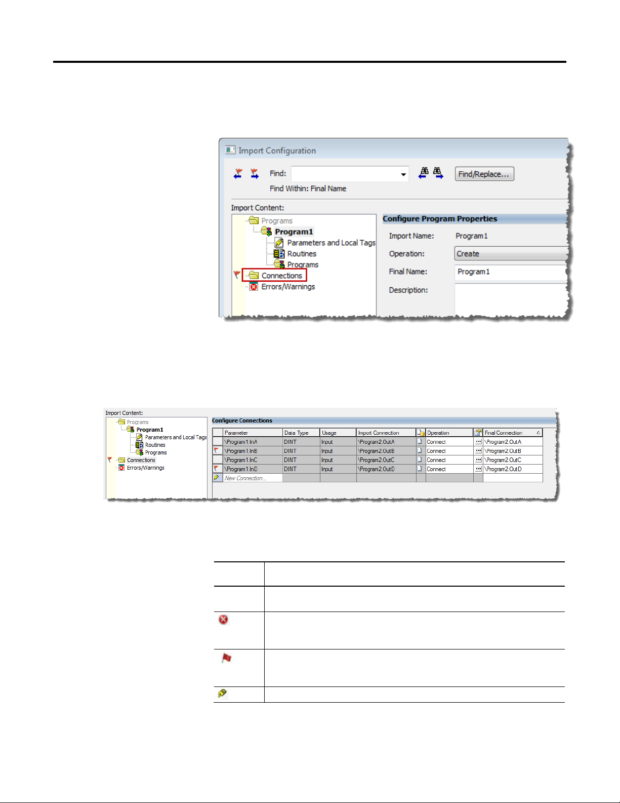
To open the Connections grid, click Connections on the Import Configuration
dialog box.
The following screen capture shows the Connections grid as it would appear
when you import Program1 into My New Project, as described earlier in this
section. To fix the connection errors, you can select Disconnect in the Operation
box, or you can select a different connection in the Final Connection box.
The indicator column at the far left of the Connections grid shows the condition
of the connection. The following table describes the connection conditions.
Indicator Connection Condition
*
Indicates a row in which content has changed and the change has not been saved.
Indicates a row in which the connection endpoints are invalid due to a syntax error. If you click OK to
begin the import, you receive an error message and must fix or remove the connection before you can
proceed.
Indicates that the connection being imported will contain an error at the completion of the import. You
can proceed with the import, and the connection is created, but you must fix the error before you can
download the project to the controller.
Indicates a row in which you can create a connection.
The following table describes the Connections grid columns and settings.
26 Rockwell Automation Publication 1756-PM019E -EN-E - October 2014
Page 27

Import and export logic components Chapter 1
Column Description
Parameter The parameter identified in this box is the parameter in the import content that is to be connected to
another parameter on a program that exists in the project.
A New Connection option is available on the last row of the grid if the import content contains only
one program. You can create connections that are not part of the import content by connecting a
program parameter in the import content to an endpoint connection on a program that is in the
project. You then have a new connection that did not exist in the import content nor in the program
that exist in the project. See Create a new connection on page 28 for more information.
Data Type Shows the data type of the parameter. A parameter can only be connected to a member or bit of a tag
or parameter with the same data type or an error occurs when you verify the program.
Usage Shows the usage type of the parameter as Input, Output, InOut, or Public.
Import Connection Shows the name of the connection endpoint for the parameter as read from the import file. This
Import Connection box is blank if the connection is only defined in the program that exists in the
project.
Differences
Indicates if there are differences between the connections in the import content and the connections
in the target project.
Also identifies if a connection exists in the import content, or if it exists in the program that is in the
project. Click the Browse button in the Details column to see more extensive component properties.
Two icons show how the imported content matches the content of the program that exists in the
project:
Indicates a connection that is present in the import content and not in the project.
Indicates a connection that is present in the project and not in the import content.
Operation Identifies whether the connection is made upon import of the program into the project. You can select
Connect or Disconnect to change the connection status for the connection.
• Connect - Upon import of the program, this connection that is defined in the import content will be
created in the project. This is the default value when a connection between the parameter and the
final connection is valid.
• Disconnect - Upon import of the project, the connection that is defined in the import content will
not be created in the project. This is the default value when the connection between the parameter
and the final connection is not valid.
See the example later in this section for more information on the Operation box.
Details
Click the Browse button to open the Connection Properties dialog box. On the Connecti on
Properties dialog box, click Connect or Disconnect to change the connection status for the
connection.
Final Connection The parameter or tag in the existing project that the import parameter will be connected to.
You have the option to change the value in the Final Connection box based on the value in the
Operation box. You can type the final connection name or click the down arrow to make a selection
from the tag browser. If the parameter is a MODULE InOut parameter, the module browser appears
instead of the tag browser. For more information about the tag browser and module browser, see the
online help topics Using the Tag Browser and Using the Module Browser.
If you enter an invalid final connection, the error indicator displays in the leftmost column. Hover the
cursor over the error indicator to see a description for the cause of the error.
See the example later in this section for more information on the Final Connection box.
Rockwell Automation Publication 1756-PM019E -EN-E - October 2014 27
Page 28

Chapter 1 Import and export logic components
Example: using the operation and final connection boxes to establish connections
Parameter in
Imported File
\Prog1.InA \Prog2.OutA Connect \Prog2.OutA This connection exists in both the import content and in the program in the
\Prog1.InB \Prog2.OutB Connect \Prog2.OutB The endpoint parameter does not exist in the target project file.
\Prog1.InB \Prog2.OutB Disconnect \Prog2.OutB Example Row 3: Parameter \Prog2.OutB does not exist in the target project, so
\Prog1.InA \Prog2.OutA Connect \Prog3.OutB Example Row 4: Parameter \Prog2.OutA does not exist in the target project, so
\Prog1.InC none Connect \Prog3.OutD
Connection in
Imported File
Operation Value Final Connection box What happened in this case
project, so the connection is the same.
If you are importing the program offline, the error flag appears. You can
continue the import, but you must resolve the error before you can download
the project to the controller.
If you are importing the program online, the red-x error appears, and you
must resolve the error before continuing the import.
To resolve the error, you can either:
• Set the Operation Value to Disconnect (see Example Row 3 in this table).
• Select an existing parameter in the Final Connection box to reassign the
connection (see Example Row 4 in this table).
you set the Operation Value to Disconnect.
in the Final Connection box select an existing parameter to reassign the
connection.
This connection did not exist, so in the Final Connection box select an existing
parameter to create the connection. See Create a new connection on page 28
for more information on creating connections.
Create a new connection
When you import one program you can create a new connection on the last row of
the Connections grid. The new connection connects a program parameter in the
import content to an endpoint connection in a program that is in the project.
Your new connection did not previously exist in the import content nor in the
project. The New Connection row is not available when you import multiple
programs with existing connections between the programs you are importing.
You can type the parameter name for the new connection or click the down arrow
to make a selection from the tag browser. Because only parameters that are in the
import content are valid for the Parameters box, only the parameters that reside
in the import content are listed in the tag browser. For more information about
the tag browser, see Using the Tag Browser in the online help.
When both the parameter and final connection have been specified, the
connection is made (added) to the connection grid after you move off the New
Connection row or after you press Enter. If you enter an invalid parameter or
final connection, the connection is not created and the error indicator displays in
the leftmost column. Hover the cursor over the error indicator to see a description
for the cause of the error.
28 Rockwell Automation Publication 1756-PM019E -EN-E - October 2014
Page 29
Import and export logic components Chapter 1
Configure component references
In addition to determining how the component is imported, you must configure
how references are imported. The references are all other components used by the
exported component at the time it was exported. For example, a program .l5x file
contains the definition of all controller-scoped tags, user-defined data types, userdefined string types, and Add-On Instructions referenced by the program at the
time the program was exported. During import configuration, you determine what
the references from the imported component connect to after import. You can
connect a reference to an existing component in the project and not import the
referenced component from the import file. Or, you can use the referenced
component in the import file either by creating a new component in the project
from the definition in the import file or by overwriting an existing component of
the same type in the project.
As with imported components, if the Final Name of a referenced component
(such as a tag) matches a component of the same type and scope in the project,
these components collide. If there is no collision, the component is identified as
needing to be created (Operation is Create).
Rockwell Automation Publication 1756-PM019E -EN-E - October 2014 29
Page 30

Chapter 1 Import and export logic components
Icons in the Differences column ( ) on the Import Configuration dialog box
show whether components collide with differences, or the component only exists
in the import file or the project.
Click the icon in the Details column ( ) and a Collision dialog box opens
showing the differences between the import component and the colliding project
component. Use the information in the Collision dialog box to determine
whether to overwrite or use the existing component.
For components that do not collide, click the same icon for more information on
the component.
A referenced component that collides with an existing component defaults to using the project component
Tip:
(Operation is Use Existing), even if the definitions of the components are different. To import the referenced
component definition from the import file, Overwrite must be selected.
Connecting a referenced component to a component of the same type, but with
another name in the project, causes any reference to the component in the
imported logic to be updated to the new name. For example, if you connect a
Boolean reference tag A to B[3].ACCUM.4 (where B is an existing tag in the
project that is an array of structures), then all references in the imported logic that
used to say A now say B[3].ACCUM.4. Another way to connect reference tags to
existing tags in the project is to modify their Alias For box. This is permitted
when the reference tag is being created or the reference tag is overwriting an
existing tag (offline only), regardless of whether it was originally an alias tag. The
Import Configuration dialog box lets you configure the references that you must
connect during the import process.
Important:
It is important to note that even if a component has an Operation of Discard, Use Existing, or
Undefined, if the Final Name differs from the Import Name, then the imported logic references to that
component are updated to reflect the Final Name. For example, if you enter an invalid name as the Final
Name for a tag reference, the Operation is set to Discard but the imported logic references to that tag are
still updated to the invalid Final Name.
30 Rockwell Automation Publication 1756-PM019E -EN-E - October 2014
Page 31
Import and export logic components Chapter 1
References configuration example
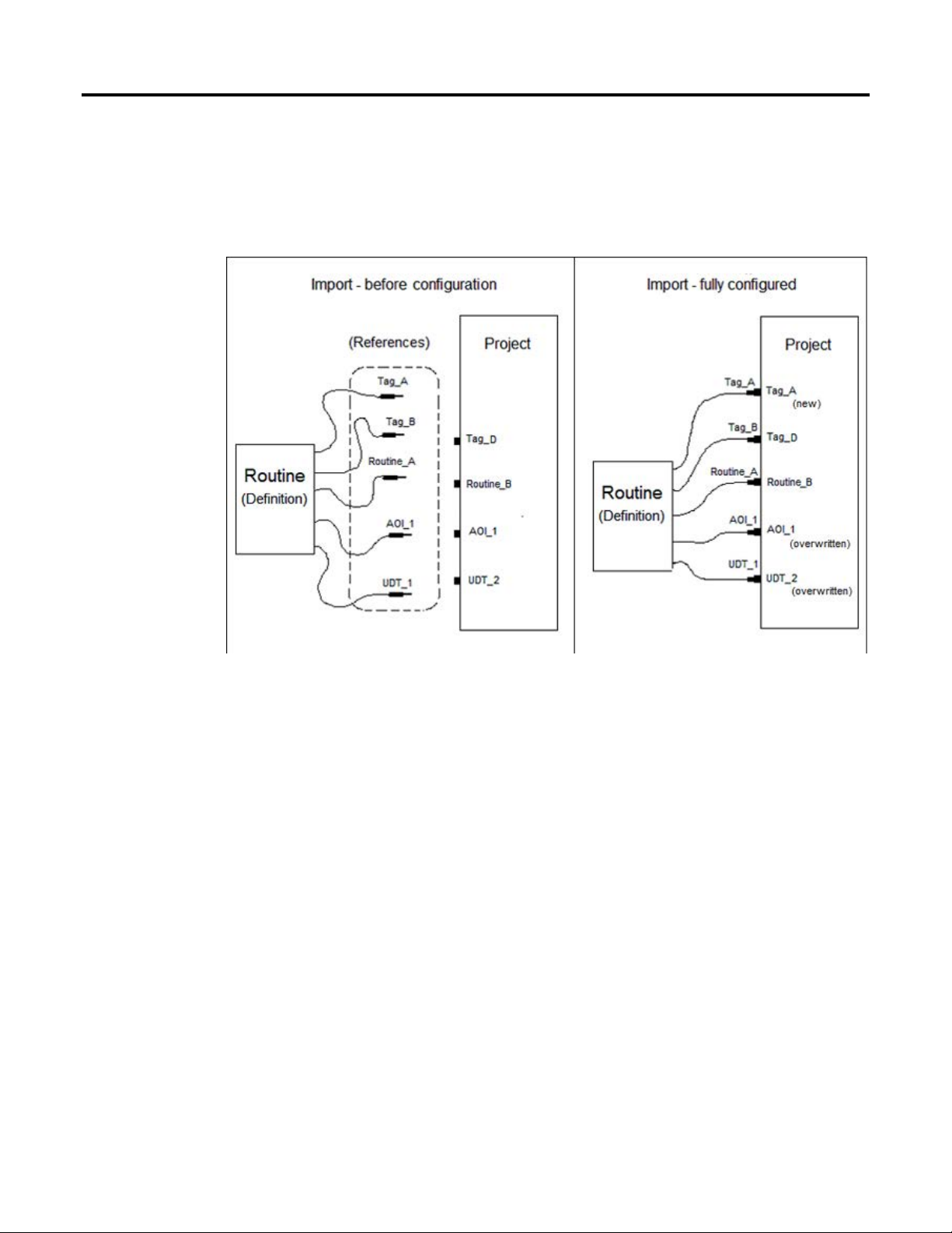
The following example shows how an imported routine plugs into the
components in a project after you configure it.
For example, if you import a routine, the routine itself is the main import
component. References that should be connected during the import could include
program-scope tags, controller-scope tags, user-defined data types, any routines
called by JSR instructions, and any Add-On Instructions in the routine logic.
In this example, a routine export file contains the definitions of Tag_A, Tag_B,
AOI_1, and UDT_1. The routine also contains a reference to Routine_A, but
excludes the logic in Routine_A.
Rockwell Automation Publication 1756-PM019E -EN-E - October 2014 31
Page 32

Chapter 1 Import and export logic components
During import configuration, connect each:
• Reference tag in the import routine to a program or controller-scoped tag in
the project.
• Reference routine in the import routine to a routine in the project.
• User-defined data type defining a reference tag in the import routine to a
user-defined data type in the project.
• Add-On Instruction in the import routine to an Add-On Instruction in the
project.
These tags, user-defined data types, and Add-On Instructions might exist in the
project, or they can be created when you import the routine.
• Tag_A is set to Create, so the imported logic referencing Tag_A references
the newly created Tag_A in the project.
Tag_B has its Final Name changed to Tag_D and is set to Use Existing, so it is
not created, and imported logic referencing Tag_B instead references existing
Tag_D.
• Routine_A has its Final Name changed to Routine_B, so imported JSRs to
Routine_A uses the existing Routine_B.
• AOI_1 is set to Overwrite an existing Add-On Instruction called AOI_1,
so not only do imported logic and tags use AOI_1, but also any existing
references to AOI_1 in the project now uses the new definition of AOI_1
from the imported routine.
• UDT_1 is set to Overwrite an existing user-defined data type called
UDT_2, so imported logic and tags use UDT_2 and the existing UDT_2 is
overwritten (except for the name) with the definition from UDT_1. Logic
and tags from the project now use the new definition of UDT_2.
Undefined references
In the Logix Designer editor, it is possible to create logic that references tag, userdefined data type, or Add-On Instruction components that do not yet exist. These
are considered undefined references. If you export that logic, there is no
component definition to export for that undefined reference. On import, these
tags, user-defined data types, or Add-On Instructions appear with an Operation
of Undefined during Import Configuration unless the component exists in the
project (in which case the Operation is Use Existing). Similarly, when logic
references any type of component other than a tag, user-defined data type, userdefined string type, or Add-On Instruction (for example, a routine that is
referenced by a JSR instruction), the definition for these referenced components
32 Rockwell Automation Publication 1756-PM019E -EN-E - October 2014
Page 33

Import and export logic components Chapter 1
Project documentation
are excluded from the import file and they also appear with an Operation of
Undefined if the component does not exist in the project.
During import configuration, these undefined references can be configured as
well. Since there is no definition for these components in the .l5x file, you cannot
overwrite a project component or create a component during the import process,
but you can use an existing component for that reference. You configure which
component in the project you want to connect the reference to, or leave the
reference undefined. An undefined reference that collides with an existing
component defaults to using the project component.
Attention flags
Attention (red) flags alert you to import situations that may be unintended or may
lead to a project that does not verify successfully after import. What they describe
may or may not prevent the import from proceeding. If online, and the project
does not verify successfully when accepting or finalizing edits, the import fails. Not
all attention flags cause a project to fail verification. The red flag indicates the
potential problem and you must decide what you want to do. You can ignore the
attention message or try to change the Final Name or Operation of the
component to resolve the issue.
Hover the cursor over the attention flag to open a tooltip that explains the issue.
Tip:
Errors and warnings on import
When an import fails or is canceled, all changes caused by the import are
discarded, leaving the project in the same state it was in before the import, even if
the project is online with the controller. If the import fails, the Import
Configuration dialog box opens with Errors/Warnings selected. To attempt to
import again, inspect the errors and warnings, reconfigure the import, and click
OK.
The Logix Designer application provides the option to set the display language for
project documentation, such as tag descriptions and rung comments, using any of
the supported localized languages. You can store project documentation for
multiple languages in one project file rather than in language-specific project files.
You define the localized languages that the project supports and set the current,
default, and optional custom localized language. The software uses the default
language if the current language's content is blank for a particular component of
the project. You can use a custom language to tailor documentation to a specific
type of project file user. When you configure project documentation in the Logix
Rockwell Automation Publication 1756-PM019E -EN-E - October 2014 33
Page 34

Chapter 1 Import and export logic components
Designer application for a project, you can dynamically switch between languages
in that project as you use the software.
The following project documentation items support multiple languages.
• Component descriptions in tags, routines, programs, equipment phases,
user-defined data types, and Add-On Instructions
• Engineering units and state identifiers added to tags, user-defined data
types, or Add-On Instructions
• Trends
• Controllers
• Alarm Messages (in configuration of ALARM_ANALOG and
ALARM_DIGITAL tags)
• Tasks
• Property descriptions for modules in the Controller Organizer
• Rung comments, Sequential Function Chart boxes, and Function Block
Diagram boxes
The export and import features of the Logix Designer application support project
documentation. You can transfer project components between projects that have
different project documentation settings.
If a component was exported to an .l5x file from a project with project
documentation turned off and is then imported into a project with project
documentation turned on, all project documentation brought in by the import is
associated with the project’s current language. If a component was exported to an
.l5x file from a project with project documentation turned on, all language
switched comments are exported with the component. When you import an .l5x
file that includes language switched comments, the Import Configuration dialog
box includes a Current Import Documentation Language selection.
34 Rockwell Automation Publication 1756-PM019E -EN-E - October 2014
Page 35

Import and export logic components Chapter 1
Find and replace
If the project has project documentation turned on, all language-switched
comments from the .l5x file are imported into the project. This may result in
additional languages being available in the project after import. Selecting a
language in Current Import Documentation Language allows you to edit that
language’s comments from the import file during the import configuration
process.
If the project does not have project documentation turned on, you can import
only one set of localized comments from the import file. In this case, selecting a
language in Documentation to Import determines which language’s comments are
imported with components from the import file. You can edit the language’s
comments during the import configuration process, but only the final language
selected when import proceeds is imported with components.
Important:
Important:
Important:
Only comments associated with imported components are brought in from the import file. If an existing
component is used, import file comments for that component are not imported.
Multiple localized alarm messages can be stored (in configuration of ALARM_ANALOG or ALARM_DIGITAL
tags) even if the project does not have project documentation turned on. Therefore, all alarm messages are
imported, regardless of the Documentation Language to Import selection on the Import Configuration
dialog box.
The Documentation Language to Import selection does not affect the setting of the language defined in the
project after import.
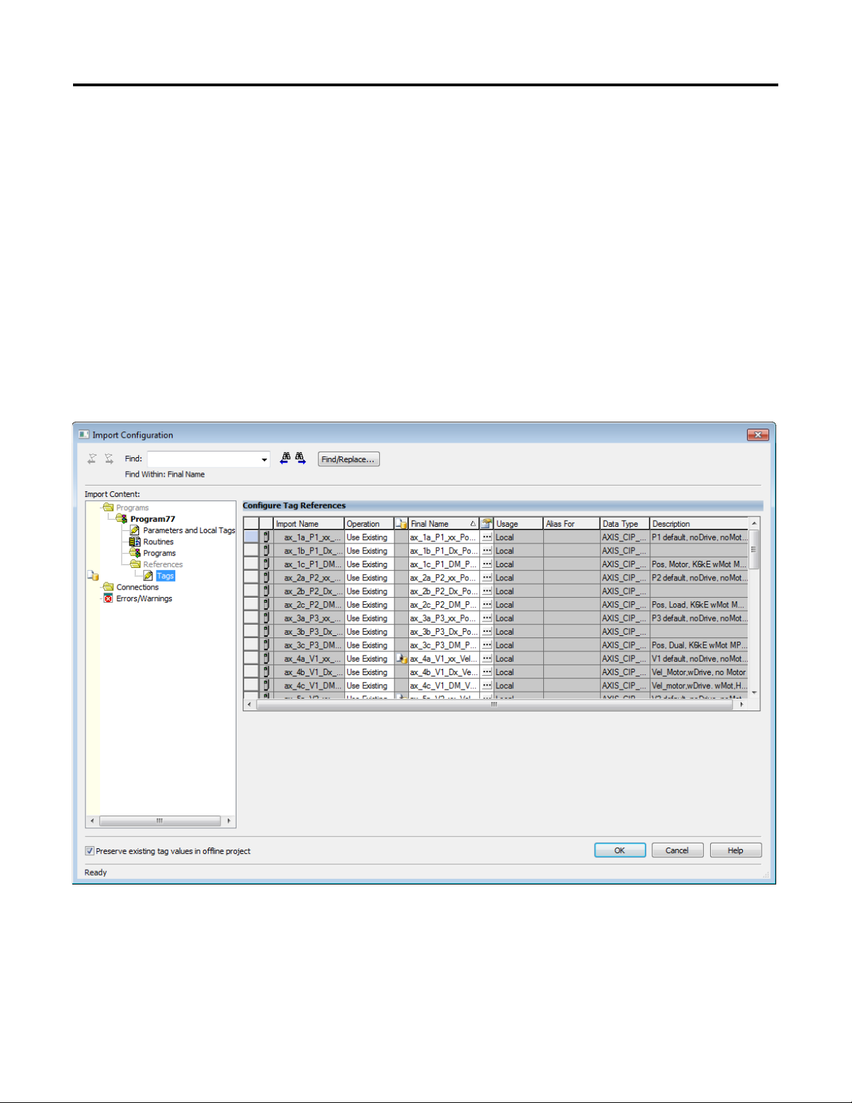
Use the Find controls in the Import Configuration dialog box control bar to
search for text within the Import Configuration dialog box. Use the Find /
Replace dialog box to configure whether the Find searches through the Import
Name, Final Name, Description, Alias For, and the Data Type check boxes. As
the search progresses, the Import Configuration dialog box automatically
switches to different panes within the dialog as needed.
You can replace text boxes during the search to facilitate development of a
component template that you can import repeatedly, replacing template text
during each import. When designing a program template, during a program
import, the program tag names and descriptions cannot be edited or replaced.
However, during import you may edit the names and descriptions of controllerscoped tags referenced from the program. Similarly, when importing an equipment
phase, you cannot edit the names and descriptions of tags in the equipment phase,
and when importing an Add-On Instruction, you cannot edit the names and
descriptions of the parameters and local tags.
Rockwell Automation Publication 1756-PM019E -EN-E - October 2014 35
Use these steps to find and replace text during the import configuration process.
1. Click Find/Replace in the Import Configuration dialog box.
2. In the Find What box, enter the desired text for the search. You can enter a
search string or select text from a previous search.
Page 36

Chapter 1 Import and export logic components
3. To replace text that is found, enter the replacement text in the Replace
With box.
To use wildcards in your search string and in the replacement text, select the
Use Wildcards check box. Use asterisks (*) as wildcard characters. This
table provides examples of Find-Replace operations using wildcards.
Find What Replace With Text Found Replacement Result
tk1_*_001 PRE_*_010 tk1_me_001 PRE_me_010
tk3_* tk4_* tk3_unit tk4_unit
*001 *002 mi_2001 mi_2002
*tank* *TNK* M1_tank_003 M1_TNK_003
* PRE_* some_name PRE_some_name
4. To limit search and replace to the currently selected pane, select the Search
current view only check box. You can change the selected pane without
closing the Find / Replace dialog box.
5. Select the applicable Find Within check boxes to configure the search.
6. Click Find Next to search for the next matching item.
7. Click Replace to replace the text in a text box. Click Replace All to replace
all instances of the search text specified in the Find What box with the text
in the Replace With box.
Compatibility
The import/export feature supports backward compatibility for import operations
and forward compatibility for export operations.
Backward compatibility means that the Logix Designer application can import
.l5k or .l5x files generated by a previous version of the application. In some cases,
an older .l5k file might not correctly import into a later version of the application.
36 Rockwell Automation Publication 1756-PM019E -EN-E - October 2014
Page 37

Import and export logic components Chapter 1
The import/export feature supports forward compatibility for export operations,
and does not support backward compatibility for export operations. Earlier
versions of the Logix Designer application cannot read .l5k or .l5x files that were
created with later versions of the application. In some cases, an .l5k or .l5x file
created with a later version of the Logix Designer application may import with
warnings into an earlier version of the application. In these cases, attributes on
components may be set to default values during import.
Each version of the Logix Designer application exports .l5k files with a specific
import/export Logix Designer application version number. The Logix Designer
application imports any .l5k file with the same major revision number and the
same or lower minor revision number. The major Logix Designer application
version number increments when file properties prevent the application from
supporting backward compatibility for import operations. The minor version
number increments whenever there is a change in the file (a new module, an
attribute is added, the set of options for an attribute is changed) that does not
affect backward compatibility for Logix Designer application import operations.
Important:
Use caution when copying and pasting components between different versions of Logix Designer
application. Logix Designer application supports pasting to only the same or later version. Pasting to an
earlier version of Logix Designer application is not supported. When pasting to an earlier version, the paste
action might succeed but the results might not be as intended.
Rockwell Automation Publication 1756-PM019E -EN-E - October 2014 37
Page 38

Page 39

Introduction
Export considerations
Import considerations
Chapter 2
Additional considerations for rungs
This chapter explains import and export of rungs.
One rung or a contiguous set of selected rungs may be exported to an .l5x file.
The export file may also include any program-scoped tags, controller-scoped tags,
Add-On Instructions, user-defined data types, and user-defined string types that
are referenced by the rungs. The definitions for the referenced tags, Add-On
Instructions, and user-defined data types are exported to the .l5x file if they exist in
the project. In the case of rungs exported from an Add-On Instruction routine,
any parameters and local tags referenced are exported if they exist at the time of
export.
When importing rungs, you configure how the referenced components are
imported during import configuration. By default, referenced components that
collide with project components are not imported.
The following table lists considerations when importing rungs.
Topic Consideration
Pending Edits exist If rungs are imported into a program or equipment phase that contains Pending Edits, all
Pending Edits in the program are accepted if Accept Program Edits is selected during
import of the rungs. Similarly, all Pending Edits in the program are finalized if Finalize All
Edits In Program is selected during import of the rungs.
Accepted Edits exist Rungs cannot be imported into a program or equipment phase that contains routines with
Accepted Edits or Test Edits. Existing edits must first either be assembled or canceled.
First scan When importing rungs into an existing program, the S:FS bit is not set during the next scan
of the program. This applies when importing rungs into an existing equipment phase as
well.
Collision handling
If you select Overwrite Selected Rungs in the Import Rungs dialog box, the imported
rungs overwrite the rungs selected in the project.
If Overwrite Selected Rungs is cleared, the imported rungs are inserted before the
selected rungs in the project if the ladder editor is in Insert mode, they are inserted after
the selected rungs if the ladder editor is in Append mode.
Rockwell Automation Publication 1756-PM019E -EN-E - October 2014 39
Page 40
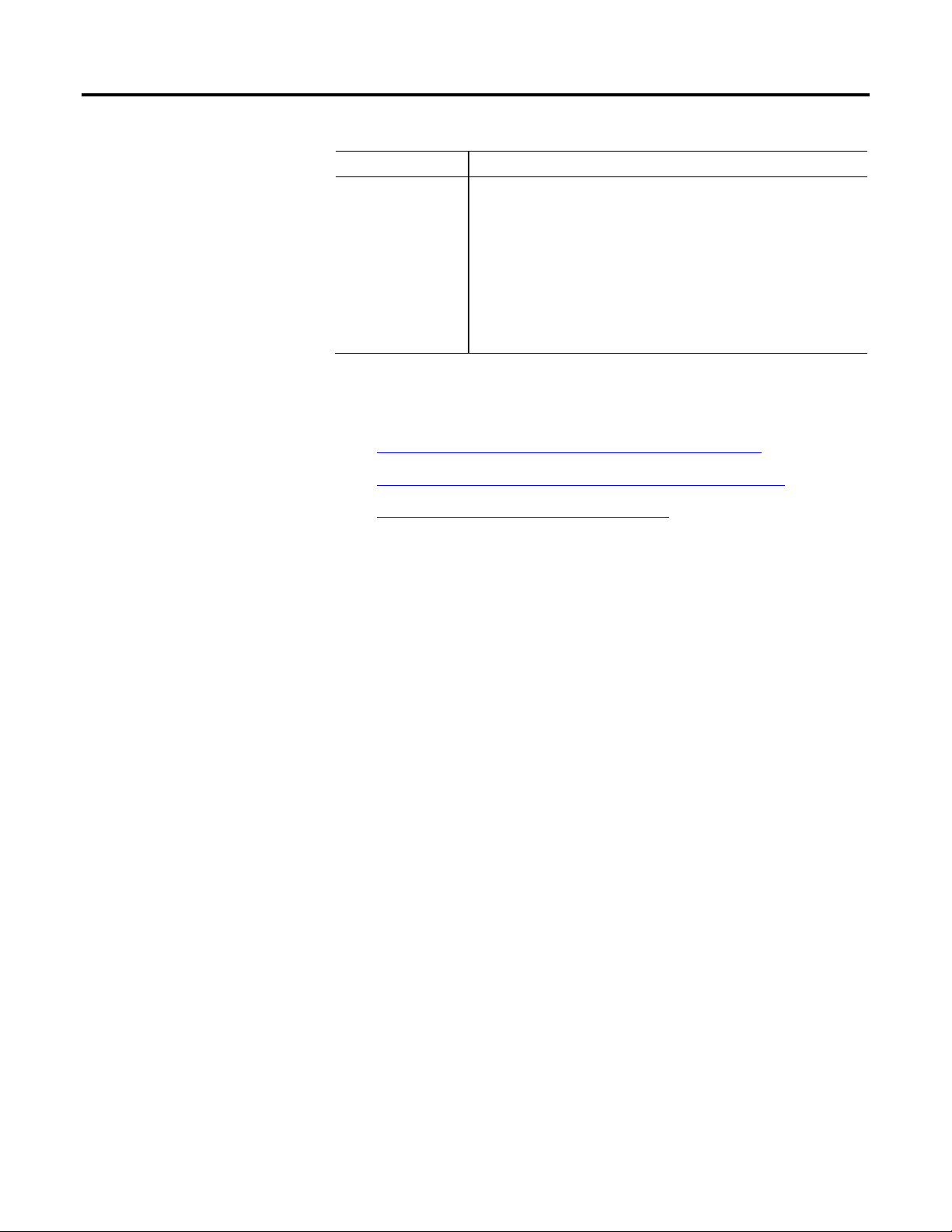
Chapter 2 Additional considerations for rungs
Topic Consideration
Tag scope When you export rungs from a program or equipment phase and import them into an Add-
On Instruction routine, any referenced controller-scoped or program-scoped tags are
converted on import. The tag is converted to a local tag unless local scoped is not allowed
(for example, a Motion Group tag cannot be a local tag), in which case the tag is converted
to an InOut parameter.
When you export rungs from an Add-On Instruction routine and import them into a routine
in a program or equipment phase, the referenced parameters and local tags are converted
on import. The parameter or local tag are converted to a program-scoped or phase-scoped
tag unless it is not allowed (for example, a Motion Group tag cannot be a program-scoped
tag), in which case it is converted to a controller-scoped tag.
For considerations for referenced user-defined types, Add-On Instructions, and
tags that may be imported with the rungs, see:
• Additional considerations for user-defined types on page 47
• Chapter 6, Import and export Add-On Instructions on page 49
• Additional considerations for tags on page 59
40 Rockwell Automation Publication 1756-PM019E -EN-E - October 2014
Page 41

If a routine is imported into a program or equipment phase that contains other routines
Edits is selected during import of the routine. Similarly, all Pending Edits in the program
Introduction
Export considerations
Chapter 3
Additional considerations for routines
This chapter explains the import and export of routines.
A routine can be exported to an .l5x file. Routines of all language types, Function
Block Diagram, Sequential Function Chart, Ladder Diagram and Structured
Text, may be exported. However, routines may not be exported from an Add-On
Instruction container and SoftLogix external routines may not be exported.
The export file may also include any program-scoped tags, controller-scoped tags,
Add-On Instructions, user-defined data types, and user-defined string types that
are referenced by the routine. The definitions for the referenced tags, Add-On
Instructions and user-defined data types are exported to the .l5x file if they exist in
the project.
Import considerations
When importing a routine, you configure how the referenced components are
imported during import configuration. By default, referenced components that
collide with project components are not imported.
The following are considerations when importing a routine.
Topic Consideration
Pending Edits exist
with Pending Edits, all Pending Edits in the program are accepted if Accept Program
are finalized if Finalize All Edits In Program is selected during import of the routine.
Accepted Edits exist A routine may not be imported into a program or equipment phase that contains
routines with Accepted Edits or Test Edits. Existing edits must first either be assembled
or canceled.
Routine type An existing routine may not be overwritten by a routine that is another routine type.
First scan When importing a routine into an existing program, the S:FS bit is not set during the
program’s next scan. This applies when importing a routine into an existing equipment
phase as well.
SFC routine execution
configuration
Equipment Phase state routines When state routines are created while online with the controller and logic edits are
SFC execution settings are configured on a controller project, not per SFC routine. If you
export an SFC routine and import it into another project with different SFC execution
settings, the functionality of the routine could change. For example, a change in the
Last Scan of Active Steps setting could leave physical outputs in an undesired state.
accepted but not tested, the routine will behave as if it was not implemented.
Rockwell Automation Publication 1756-PM019E -EN-E - October 2014 41
Page 42

Chapter 3 Additional considerations for routines
For considerations for referenced user-defined types, Add-On Instructions, and
tags that may be imported with the rungs see:
• Additional considerations for user-defined types on page 47
• Chapter 6, Import and export Add-On Instructions on page 49
• Additional considerations for tags on page 59
42 Rockwell Automation Publication 1756-PM019E -EN-E - October 2014
Page 43

Introduction
Export considerations
Import considerations
Chapter 4
Additional considerations for programs and
equipment phases
This chapter explains import and export of programs. All topics apply to
equipment phases as well; any exceptions are noted.
A program can be exported to an .l5x file. The exported program includes all of its
program tags and routines, which are imported with the program automatically.
The export file may also include any controller-scoped tags, Add-On Instructions,
user-defined data types, and user-defined string types referenced by the program.
The definitions for the referenced tags, Add-On Instructions, and user-defined
data types are exported to the .l5x file if they exist in the project.
As with other export types, I/O module data type definitions are not exported.
I/O module data types are created within a project when the associated I/O
module is created in the project. On import, program-scoped tags may not be
modified. As a result, if a program-scoped tag aliases an I/O module type tag, the
I/O module must first exist in the project in order to import the program. To
export the program so that it can be imported into a project with another module
type, first alias the program-scoped tag to a controller-scoped tag of a non-I/O
module type, and then alias the controller-scoped tag to the I/O module. These
program-scoped tags can then be created during the import of the program if
necessary.
When you import a program, the program-scoped tags and routines are imported
as part of the program. The Operation, Final Name, Description, and any other
settings of the program-scoped tags and routines cannot be modified; instead, the
Operations are based on the Operation selected for the program.
Programs cannot overwrite equipment phases, and vice-versa. Programs and
equipment phases must have unique names.
You configure how the referenced components are imported during import
configuration. By default, referenced components that collide with project
components are not imported.
Rockwell Automation Publication 1756-PM019E-EN-E - October 2014 43
Page 44

Chapter 4 Additional considerations for programs and equipment phases
The following are considerations when importing a program.
Topic Consideration
Accepted or Test Edits exist A program with Accepted Edits or Test Edits may not be overwritten.
Deletes of program-scoped tags and routines
during program overwrite
Safety program scheduled location
Configuration of Equipment Phase state routines
First scan
Pre-scan
When importing a program to replace an existing program, any tags or routines in the existing program that are not in the new
program are deleted during import. However, if you are online and import Logic Edits as Pending or Accept Program Edits is
selected in the Online Options dialog box, then these tags and routines cannot be deleted because they are referenced by
existing logic until edits are finalized. In this situation, although they were identified during import configuration with an
Operation of Delete, these tags and routines are not deleted as part of the import. You can delete them in the Logix Designer
editor after you finalize edits.
A Safety program cannot be scheduled in the Controller Fault Handler or Power-Up Handler folders.
In the configuration for an equipment phase state routine, when the Complete State Immediately if not Implemented
option is selected in version 17 and later of the application, an implemented, but empty (no logic), phase state routine behaves
the same as an unimplemented phase state routine. The state immediately completes and execution of the phase continues. The
phase then enters the next state in the state machine.
In version 16 or later of the application, if an equipment phase enters a state for which a state routine exists, but contains no
logic, execution of the phase stops regardless of whether the Complete State Immediately if not Implemented option is
selected. The routine does complete, but there is no logic to run.
If you import a new state routine and, in the Online Options dialog box, you select:
• Import Logic Edits as Pending, an empty routine is created in the controller and the pending edits only exist in the offline
project.
• Accepts Program Edits, an empty routine is created in the controller and the logic is placed in a test edits container in the
routine. If you are not actively testing edits, the routine is empty when running.
• Finalize All Edits in Program, the routine is created with the new logic and is not empty.
In the first two cases, if the Complete State Immediately if not Implemented option is selected, the empty routine
completes immediately and allows phase execution to continue.
If a new program or equipment phase is created in a controller in Remote Run mode, logic in that program/equipment phase
receives a value of 1 for the S:FS system flag (First Scan flag) until the main routine has run once.
Any other logic imports (that is overwriting an existing program or equipment phase, or any routine or rung imports) does not
result in a value of 1 for S:FS system flag.
Logic imported while online with the controller in Remote Run mode is not be pre-scanned before it begins to run.
Program scheduled location while online An imported program that is configured to overwrite an existing program cannot be scheduled into a location that differs from
the existing program while online with the controller in Remote Run mode; the existing scheduled location is used.
Renamed tags When overwriting an existing program and the imported program is modified such that a program-scoped tag has been
renamed, during import, the existing tag is deleted and a tag with the new name is created. All logic references are updated to
reference the new tag. Therefore, the online tag values are not preserved and the tag values from the imported tag are
downloaded to the controller. To preserve the data values of the renamed tag and minimize the logic changes, rename the
program tag in the online project to the new name before importing the modified program.
Importing multiple programs
Controller Fault Handler and Power-Up Handler Disabled: When you import multiple target programs, the Controller Fault
Handler and Power-Up Handler are unavailable in the Schedule In list.
For considerations for referenced user-defined types, Add-On Instructions, and
program tags, and referenced tags that may be imported with a program see:
• Additional considerations for user-defined types on page 47
• Chapter 6, Import and export Add-On Instructions on page 49
• Additional considerations for tags on page 59
44 Rockwell Automation Publication 1756-PM019E -EN-E - October 2014
Page 45

Introduction
Export considerations
Import considerations
Chapter 5
Additional considerations for user-defined types
This chapter explains import and export of user-defined data types and user-
defined string types.
A user-defined type or user-defined string type can be exported to an .l5x file.
The export file may also include any Add-On Instructions, user-defined data
types, and user-defined string types referenced by the exported user-defined type.
The definitions for the referenced Add-On Instructions and data types are
exported to the .l5x file if they exist in the project and if Include all referenced
Add-On Instructions and User-Defined Types is selected during export.
You can also export User-Defined data type references when a program, routine,
set of rungs, or Add-On Instruction is exported.
When importing a user-defined type, you configure how the referenced
components are imported during import configuration. By default, referenced
components that collide with project components are not imported.
User-defined types cannot overwrite Add-On Instructions. User-defined types
and Add-On Instructions must have unique names.
The following are considerations when importing a user-defined type.
Topic Consideration
Tag data Imported tags that reference a user-defined data type in the import file may be affected
if the user-defined data type is not imported. In this case, the imported data of the tag
may be converted if the existing data structure is different, and tag data may be lost.
If an existing User-Defined data type is overwritten, project tag data may be converted if
the data structure is different and tag data may be lost.
Data type modification while
online
Final Name change If the Final Name of a user-defined type reference is modified during import
A User-Defined data type that is referenced in the project may not be overwritten. If the
existing User-Defined data type is not referenced, it may be overwritten while online.
configuration, all logic, tags, Add-On Instructions, and other user-defined types in the
import that reference the user-defined type are updated to reference the new name. The
edit date of any Add-On Instructions that references the user-defined type is updated.
Rockwell Automation Publication 1756-PM019E -EN-E - October 2014 45
For considerations for referenced Add-On Instructions that may be imported
with the user-defined type see Import and export Add-On Instructions on page 47
and Import and export Add-On Instructions on page 47.
Page 46

Chapter 5 Additional considerations for user-defined types
46 Rockwell Automation Publication 1756-PM019E-EN-E - October 2014
Page 47

Introduction
Create export files
Chapter 6
Import and export Add-On Instructions
This chapter explains import and export of Add-On Instructions.
When you export an Add-On Instruction, the exported Add-On Instruction
includes all of its parameters, local tags, and routines. These are imported with the
Add-On Instruction automatically.
Optionally, you can include any nested Add-On Instructions or user-defined data
types that are referenced by the exported Add-On Instruction. Referenced AddOn Instructions and data types are exported to the .l5x file if you select the
Include all referenced Add-On Instructions and User-Defined Types check
box during the export.
Add-On Instruction definition references can be exported when a program,
routine, set of rungs, or user-defined data type is exported.
If an Add-On Instruction uses Message (MSG) instruction and InOut parameters of type MESSAGE, you can export a
Tip:
rung containing the Add-On Instruction to include the MESSAGE tags. This captures the message configuration
data, such as type and path.
In deciding how to manage your Add-On Instruction definitions in export files,
consider your goals in storing the definitions.
If Then
You want to store many Add-On Instructions that share a set of common Add-On
Instructions or user-defined data types in a common location
You want to distribute an Add-On Instruction as one file Export to one file. See Ex port
You want to manage each Add-On Instruction as a standalone instruction
You want to preserve the instruction signature on your Add-On Instruction
Export to separate files. See
Export to separate files on
page 48.
to one file on page 49.
Add-On Instructions with instruction signatures are encrypted upon export to prevent modifications to the export
Tip:
file.
Rockwell Automation Publication 1756-PM019E -EN-E - October 2014 47
Page 48

Chapter 6 Import and expor t Add-On Instructions
Export to separate files
If you want to store many Add-On Instructions that share a set of common AddOn Instructions or user-defined data types in a common location, you can export
each Add-On Instruction and user-defined data types to separate files without
including references.
Follow these steps to export to separate files.
1. Right-click the Add-On Instruction in the Controller Organizer, and
choose Export Add-On Instruction.
2. Select the common location to store the .l5x file.
3. In the File name box, type a name for the file.
4. Clear the Include all referenced Add-On Instructions and User-Defined
Types check box.
5. Click Export.
6. Repeat the previous steps to individually export the other shared Add-On
Instructions and user-defined data types.
By using export in this way, you manage the shared Add-On Instruction and userdefined data types independently of the Add-On Instructions that reference them.
Using this approach, you can update the shared component without regenerating
all the export files for the instructions that reference it. That is, it is stored in only
one file instead of in every file whose instruction references it. This approach
48 Rockwell Automation Publication 1756-PM019E -EN-E - October 2014
Page 49

Import and export Add-On Instructions Chapter 6
makes it easier to maintain the instructions because you have to update only one
export file.
To use Add-On Instructions that were exported in a separate file without
references, you must first import any user-defined data types of Add-On
Instructions that the exported instruction references before the import of the
referencing instruction can be successful. This assumes that the referenced userdefined data types of Add-On Instructions do not exist in your project. To do this,
work from the bottom up. Import the lowest-level user-defined data types and any
user-defined data types that reference them. Then, import the lowest-level AddOn Instructions, followed by any Add-On Instructions that reference those lowlevel Add-On Instructions. Once all items referenced by the Add-On Instruction
are in place, the import of the Add-On Instruction succeeds.
Export to one file
If you manage each Add-On Instruction as a standalone, you can export the
instruction and any referenced Add-On Instructions or user-defined data types
into one export file. By including any referenced Add-On Instructions or userdefined data types, you also make it easier to preserve the instruction signature of
an Add-On Instruction.
Follow these steps to export to one file and include any referenced items.
1. Right-click the Add-On Instruction in the Controller Organizer and
choose Export Add-On Instruction.
Rockwell Automation Publication 1756-PM019E -EN-E - October 2014 49
Page 50
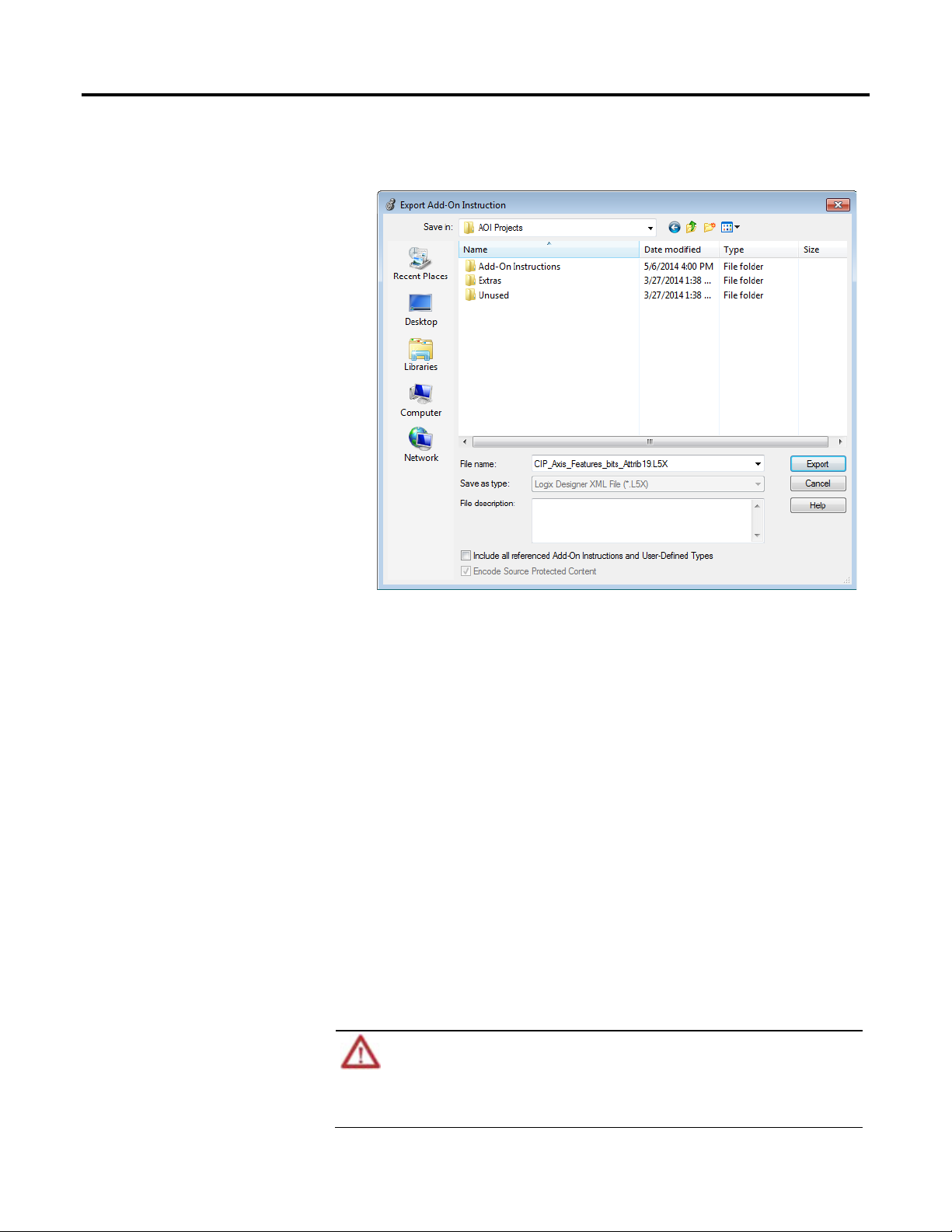
Chapter 6 Import and expor t Add-On Instructions
Import an Add-On
2. Select the location to store the .l5x file.
Instruction
3. In the File name box, type a name for the file.
4. Select the Include all referenced Add-On Instructions and User-Defined
Types check box.
5. Click Export.
This procedure exports the selected Add-On Instruction and all referenced
instructions into the same export file. This file can be used to distribute an AddOn Instruction. When the exported Add-On Instruction is imported into the
project, the referenced instructions are also imported in one step.
You can import an Add-On Instruction that was exported from another Logix
Designer project. When importing an Add-On Instruction, the parameters, local
tags, and routines are imported as part of the Add-On Instruction. Once the
project has the Add-On Instruction, you can use it in your programs.
Import considerations
50 Rockwell Automation Publication 1756-PM019E -EN-E - October 2014
Editing an .l5k or .l5x File
The EditedDate attribute of an Add-On Instruction must be updated if the Add-On Instruction is modified by
editing an .l5k or .l5x file.
If the Logix Designer application detects edits to the Add-On Instruction, but the Edited Date attribute is the
same, the Add-On Instruction is not imported.
Page 51

Import and export Add-On Instructions Chapter 6
When importing Add-On Instructions directly or as references, consider these
guidelines.
Topic Consideration
Tag Data Imported tags that reference an Add-On Instruction in the import file may be affected if the
Add-On Instruction is not imported as well. In this case, the imported tag’s data may be
converted if the existing Add-On Instruction’s data structure is different. Tag data may be
lost.
If an existing Add-On Instruction is overwritten, project tag data may be converted if the
Add-On Instruction’s data structure is different. Tag data may be lost.
See Import configuration on page 58 for more information.
Logic Imported logic that references the Add-On Instruction in the import file may be affected if
the Add-On Instruction is not imported. If an existing Add-On Instruction is used for the
imported logic reference and the parameter list of the Add-On Instruction in the project is
different, the project may not verify or it may verify but not work as expected.
If an existing Add-On Instruction is overwritten, logic in the project that references the AddOn Instruction may be affected. The project may not verify or may verify but not work as
expected.
See Import configuration on page 58 for more information.
Add-On Instructions While
Online
Final Name Change If the Final Name of an Add-On Instruction is modified during import configuration, the edit
User-defined data types Add-On Instructions cannot overwrite user-defined data types. Add-On Instructions and
Instruction Signature If you import an Add-On Instruction with an instruction signature into a project where
Safety Add-On Instructions You cannot import a safety Add-On Instruction into a standard project.
An Add-On Instruction cannot be overwritten during import while online with the controller,
though a new Add-On Instruction may be created while online.
date of the imported Add-On Instruction is updated. In addition, all logic, tags, user-defined
data types, and other Add-On Instructions in the import file that reference the Add-On
Instruction are updated to reference the new name. As a result, the edit date of any Add-On
Instruction that references the Add-On Instruction is up dated.
Add-On Instructions that are sealed with an instruction signature cannot be renamed during
impor t.
user-defined data types require unique names.
referenced Add-On Instructions or user-defined data types are not available, you may need
to remove the signature.
You can overwrite an Add-On Instruction that has an instruction signature by importing
another Add-On Instruction with the same name into an existing routine. Add-On
Instructions that are sealed with an instruction signature cannot be renamed during import.
You cannot import a safety Add-On Instruction into a safety project that has been safetylocked or one that has a safety task signature.
You cannot import a safety Add-On Instruction while online.
Class, instruction signature, signature history, and safety instruction signature, if it exists,
remain intact when an Add-On Instruction with an instruction signature is imported.
Important:
Importing an Add-On Instruction created in version 18 or later of the application, into an earlier project that
does not support Add-On Instruction signatures causes the Add-On Instruction to lose attribute data and the
instruction may no longer verify.
Rockwell Automation Publication 1756-PM019E -EN-E - October 2014 51
Page 52

Chapter 6 Import and ex port Add-On Instructions
Import Configuration
When you select a file to import, you use the Import Configuration dialog box to
choose how the Add-On Instruction and referenced components are imported.
If no issues exist, you can click OK to complete the import.
If your Add-On Instruction collides with an Add-On Instruction in the project,
you can:
• Rename it by typing a new, unique name in the Final Name box.
• Choose Overwrite from the Operation menu.
• Choose Use Existing from the Operation menu.
You can rename an Add-On Instruction only if it has not been sealed with an instruction signature.
Tip:
To rename an Add-On Instruction that has been source-protected, you need the source key.
52 Rockwell Automation Publication 1756-PM019E -EN-E - October 2014
Page 53

Import and export Add-On Instructions Chapter 6
The Collision Details button lets you view the Property Compare tab, which
shows the differences between the two instructions, and the Project References
tab, which shows where the existing Add-On Instruction is used and how the
arguments are updated to locations where the existing Add-On Instruction is
called.
Update an Add-On Instruction to a later revision using import
When you must update an instruction to a later revision, you can import it from
an .l5x file or copy it from an existing project. You must be offline to update an
Add-On Instruction.
Follow these steps to update an Add-On Instruction to a later revision by
importing it.
1. Right-click the Add-On Instruction folder and choose Import Add-On
Instruction.
2. Select the file with the Add-On Instruction and click Open.
3. From the Operation list on the Import Configuration dialog box, click
Overwrite.
Rockwell Automation Publication 1756-PM019E -EN-E - October 2014 53
Page 54
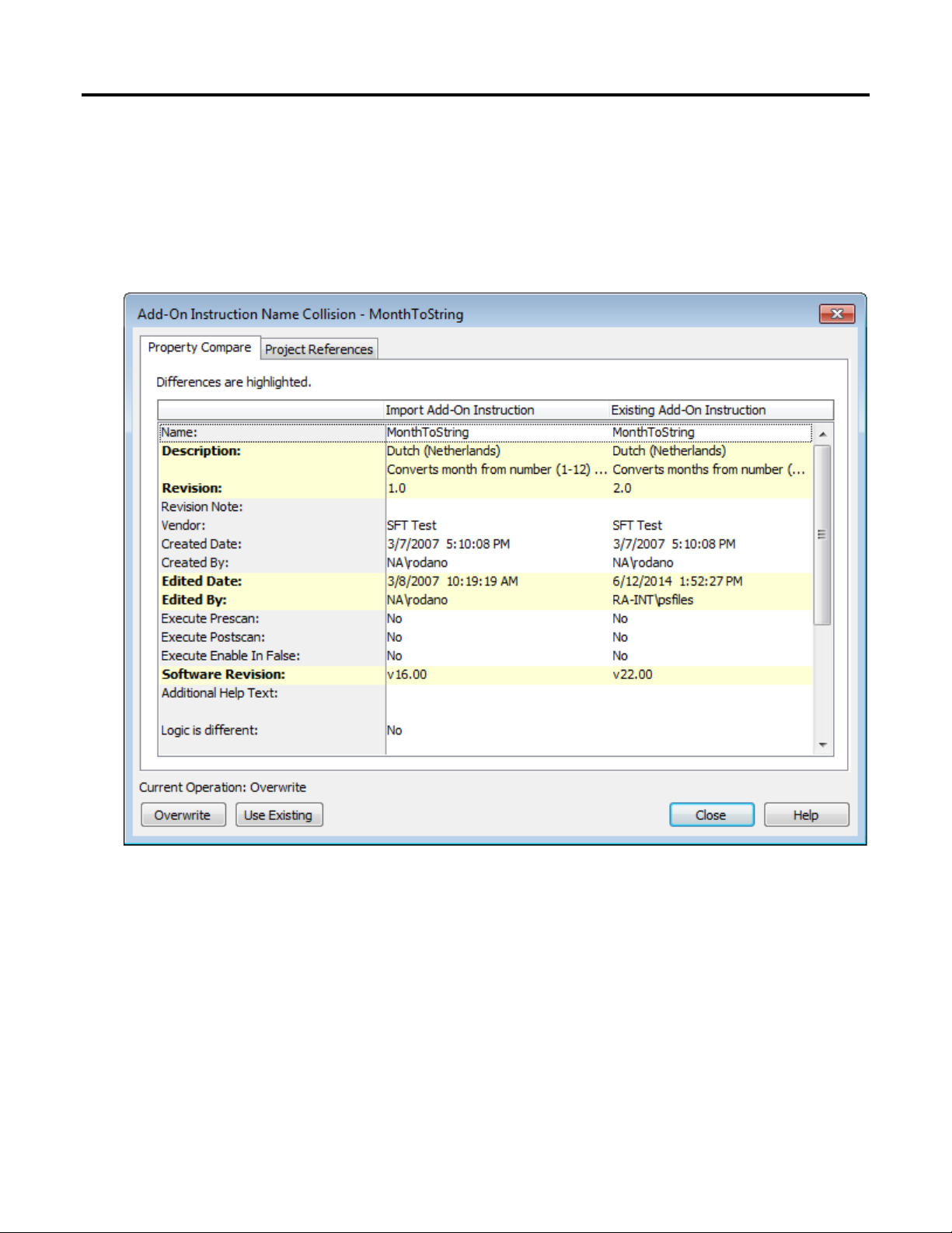
Chapter 6 Import and expor t Add-On Instructions
4. Click Collision Details to see any differences in the Add-On Instruction
definition, and to see any changes that will be made to the logic where the
Add-On Instruction is called.
Differences listed in the Property Compare tab are shown in bold in the
Name column.
Tip:
The Compare dialog box compares metadata for each instruction definition, such as description, revision, or
edited date. For effective revision control, enter a detailed revision note in the Add-On Instructions
Definition dialog box. To open the dialog box, right-click an Add-On Instruction and click Open Definition.
54 Rockwell Automation Publication 1756-PM019E -EN-E - October 2014
Page 55

Import and export Add-On Instructions Chapter 6
The Project References tab shows a list of locations where the Add-On
Instruction is called, and for each location, shows how the arguments in the
Add-On instruction will be updated to adapt to the new parameters.
Important:
Important:
Beginning with version 18, when you change the parameters of an Add-On Instruction (when you add,
delete, or move), each location where the Add-On Instruction is called is modified so that the existing
arguments continue to match their previous parameters. Importing and Overwriting an existing Add-On
Instruction may cause changes to the existing logic that uses the Add-On Instruction.
If the logic calling the Add-On Instruction is within a source-protected routine, and the key is not available,
the arguments are not shown or updated. Instead, the Location will be identified as Source Not Editable.
For more information on updates to arguments, see Logix5000 Controllers
Add-On Instructions, publication 1756-pm010.
5. Click Close and then OK to complete the operation.
Rockwell Automation Publication 1756-PM019E -EN-E - October 2014 55
Page 56

Page 57

Introduction
Export considerations
Import considerations
Chapter 7
Additional considerations for tags
This chapter explains import and export of referenced tags.
Starting with version 24 of Logix Designer application, you can use program parameters to share data between
Tip:
programs in much the same way that you use controller-scoped tags. Program parameters are imported and
exported in the same way as tags in most instances. For more information on program parameters, see
Controllers Program Parameters Programming Manual, publication 1756-PM021.
Tags are not exported to an .l5x file themselves, but they are exported to the .l5x
file as part of a program, equipment phase, or Add-On Instruction export
(program-scoped tags with a program export, equipment phase-scoped tags with
an equipment phase export, and parameters and local tags with an Add-On
Instruction export).
Logix5000
Tags may also be exported to an .l5x file as references from another component
being exported (controller-scoped tag references with a program or equipment
phase export or program-scoped and controller-scoped tag references with a rung
or routine export). The definitions for the referenced tags are exported to the .l5x
file by default if they exist in the project.
When exporting logic, especially if it is intended for general use, be aware that
logic that references a bit member of a tag or member of a user-defined data type
tag cannot be replaced during import to reference another bit or user-defined data
type member. If you expect to connect the logic reference to another bit or
member of a tag, consider editing the logic before export so the reference is to a full
tag name (and alias if need be) so that the reference can be connected to the
desired tag on import.
When you import a program, the program-scoped tags are imported with the
program automatically (the same as they are for equipment phase). When you
import an Add-On Instruction, the parameters and local tags are imported with
the Add-On Instruction automatically.
During program or equipment phase imports, referenced controller-scoped tags
may also be imported. For routine and rung imports, referenced tags may be
imported as well. You configure how referenced tags are imported during import
configuration. By default, referenced tags that collide with project components are
not imported.
Rockwell Automation Publication 1756-PM019E -EN-E - October 2014 57
Keep the following considerations in mind when importing tags.
Page 58

Chapter 7 Additional considerations for tags
Topic Consideration
Tag data Imported tags that reference an Add-On Instruction or user-defined data type in the import
file may be affected if the Add-On Instruction or user-defined data type is not imported as
well. In this case, the imported data for the tag may be converted if the existing data
structure is different and tag data may be lost.
If an existing Add-On Instruction or user-defined data type is overwritten, project tag data
may be converted if the data structure is different and tag data may be lost.
If the data is not convertible, it is overwritten with the default values for the type. When
array dimensions are changed, existing array members retain their values and descriptions
and new members have the default values and description (usually 0 and no description).
Consumed tags Consumed tags cannot be imported from an .l5x file. They are converted to base tags and a
warning appears in the Errors/Results Pane during initial parsing of the .l5x file.
Tag values while online When importing into a controller while online, if existing tags are being overwritten by
imported tags, the tag values are not written to the controller. Tag values are written only to
the offline project. The tag values in the controller maintain their current values but other
tag attributes are written to the controller.
Values for tags that are created during import are written to the controller. However,
existing tag values are never overwritten in the online controller.
You can prevent tag values from being overwritten in the offline project by selecting
Preserve existing tag values in offline project on the Import Configuration dialog
box.
Tag values while offline You can prevent tag values from being overwritten in the offline project by selecting
Preserve existing tag values in offline project on the Import Configuration dialog
box.
Tag attributes while online Tag attributes (for example, External Access, Constant, and Style) are written to the online
project and the offline project.
If existing tags are overwritten with new attributes that are incompatible with existing user
logic, the import is not allowed.
Tag scope An import tag maintains the scope of the tag as it was when exported if the tag initially
collides with another scoped tag in the project. In that case, an attention (red) flag appears
on the tag indicating the scope collision. However, If you change the Final Name of a tag so
that it subsequently collides with a tag of another scope in the project, the imported tag is
changed to the scope of the existing tag.
You can resolve the attention flag that appears on initial collision due to a scope issue by
changing the Final Name to avoid the collision with that tag or, if the import component is
routine or rungs, you can change the scope of the import tag by right-clicking on the tag row
and selecting Toggle Tag Scope.
58 Rockwell Automation Publication 1756-PM019E-EN-E - October 2014
Page 59

A
Index
Add-On Instruction 53
export 13
import 19
attention flags 37
B
backward compatibility 41
C
canceled import 37
collision
import 58, 59
communication timeouts 14, 57
compare instructions 59
component
configuration 58
export 11, 13
import 11, 19
configuration
attention flags 37
components 58
example 35
import 33, 58
options 20, 57
references 33
undefined references 36
Connections grid 32
considerations
export 12
import 57
motion 17
online import 14
safety 17
security 18
D
description
export 13
E
equipment phase 47
export 13
export considerations 65
import 19
import considerations 57
export
Add-On Instruction 53
component description 13
components 11, 13
considerations 12
equipment phase 47
L5X 11, 13
local tag 65
parameter 65
program 47
routine 45
rungs 43
tag 65
user-defined data type 51
user-defined string type 51
export considerations
equipment phase 65
local tag 65
parameter 65
program 65
routine 65
rungs 65
tag 65
user-defined data type 65
user-defined string type 65
exportIXexport 53
F
failed import 37
find
text 40
use wildcards 40
I
import
Rockwell Automation Publication 1756-PM019E -EN-E - October 2014 59
Page 60

Index
Add-On Instruction 53
canceled 37
components 11, 19
configuration 33, 58
considerations 57
equipment phase 47
failed 37
L5X 11, 19
local tag 65
multiple components 24
parameter 65
program 47
routine 45
rungs 43
tag 65
user-defined data type 51
user-defined string type 51
Import Configuration dialog box 59
import considerations
equipment phase 57
local tag 57
multiple components 18
parameter 57
program 57
routine 57
rungs 57
tag 57
user-defined data type 57
user-defined string type 57
importIXimport 56
L
L5X
export 11, 13
import 11, 19
local tag
export considerations 65
import considerations 57
M
motion 17
multiple components 18, 24
O
online import 14
P
parameter
export considerations 65
import considerations 57
program 47
export 13
export considerations 65
import 19
import considerations 57
Project References tab 59
Property Compare tab 59
R
references
configuration 33
undefined 36
replace
text 40
routine 45
export 13
export considerations 65
import 19
import considerations 57
rungs 43
export 13
export considerations 65
import 19
import considerations 57
S
safety 17
safety Add-On Instruction
import 57
safety task signature 57
search and replace 40
security 18
T
tag 65
60 Rockwell Automation Publication 1756-PM019E -EN-E - October 2014
Page 61

Index
export considerations 65
import considerations 57
tooltip
attention flags 37
trend
export 13
import 19
U
undefined references 36
update Add-On Instruction revision 59
user-defined data type 51
export 13
export considerations 65
import 19
import considerations 57
user-defined string type 51
export 13
export considerations 65
import 19
import considerations 57
UTF-8 file format 11
W
wildcards 40
X
XML files 11
Rockwell Automation Publication 1756-PM019E -EN-E - October 2014 61
Page 62

Rockwell Automation support
Rockwell Automation provides technical information on the web to assist you in using its products. At
http://www.rockwellautomation.com/support
service packs. You can also visit our Support Center at https://rockwellautomation.custhelp.com for software updates, support chats
and forums, technical information, FAQs, and to sign up for product notification updates.
In addition, we offer multiple support programs for installation, configuration, and troubleshooting. For more information, contact
your local distributor or Rockwell Automation representative, or visit http://www.rockwellautomation.com/services/online-phone
Installation assistance
If you experience a problem within the first 24 hours of installation, review the information that is contained in this manual. You can
contact Customer Support for initial help in getting your product up and running.
United States or Canada 1.440.646.3434
Outside United States or Canada Use the Worldwide Locator available at http: //www.rockwellautomation.com/locations, or contact your local Rockwell
New product satisfaction return
Rockwell Automation tests all of its products to ensure that they are fully operational when shipped from the manufacturing facility.
However, if your product is not functioning and needs to be returned, follow these procedures.
you can find technical and application notes, sample code, and links to software
Automation representative.
.
United States Contact your distributor. You must provide a Customer Support case number (call the phone number above to obtain one) to
your distributor to complete the return process.
Outside United States Please contact your local Rockwell Automation representative for the return procedure.
Documentation feedback
Your comments will help us serve your documentation needs better. If you have any suggestions on how to improve this document,
complete the feedback form, publication RA-DU002
.
Rockwell Automation Publication 1756-PM019E-EN-E – October 2014
Supersedes Publication 1756-PM019D-EN-P - September 2012 Copyright © 2014 Rockwell Automation, Inc. All rights reserved. Printed in the U.S.A.
 Loading...