

Page 1
Installation Instructions
Stegmann Feedback Option Board for
PowerFlex
!
!
!
®
700S Drives
ATTENTION: To avoid an electric shock hazard, verify that the
voltage on the bus capacitors has discharged completely before
servicing. Check the DC bus voltage at the Power Terminal
Block by measuring between the +DC and -DC terminals,
between the +DC terminal and the chassis, and between the -DC
terminal and the chassis. The voltage must be zero for all three
measurements.
ATTENTION: HOT surfaces can cause severe burns. Do not
touch the heatsink surface during operation of the drive. After
disconnecting power allow time for cooling.
ATTENTION: This drive contains ESD (Electrostatic
Discharge) sensitive parts and assemblies. Static control
precautions are required when installing, testing, servicing or
repairing this assembly. Component damage may result if ESD
control procedures are not followed. If you are not familiar with
static control procedures, reference A-B publication 8000-4.5.2,
“Guarding Against Electrostatic Damage” or any other
applicable ESD protection handbook.
What This Kit Contains
Tools That You Need
ATTENTION: The sheet metal cover and mounting screws on
the ASIC Board located on the power structure are energized at
!
(-) DC bus potential high voltage. Risk of electrical shock, injury,
or death exists if someone comes in contact with the assembly.
Verify that your kit contains the items listed in the following table. If your
kit does not contain the correct items, contact your Rockwell Automation
sales representative.
Quantity: Description
1 Stegmann Feedback Option circuit board
2 34 - pin “stacker” connectors
Important: The part number of the stacker connectors in Phase I drives is 313611.
The part number for the stacker connectors used in Phase II drives is 320669-Q04.
3 Screws with captive lock washers
3 Stand-offs (for Phase i drives only)
• Phillips® screwdriver for M3 screws
• POZIDRIV
• Nut driver or wrench for M3 hex nut
• Nut driver or wrench for M5 hex nut
Phillips® is a registered trademark of Phillips Screw Company
POZIDRIV
®
®
screwdriver for M4 screws (for high power drives only)
is a registered trademark of Phillips Screw Company
Page 2

2 Stegmann Feedback Option Board for PowerFlex® 700S Drives
What You Need to Do
To remove the Stegmann Feedback option board from the PowerFlex 700S
drive:
❐Step 1: Remove power from drive
❐Step 2: Remove cover(s) from drive
❐Step 3: Remove control assembly from drive
❐Step 4: Remove feedback option board
To install the new Stegmann Feedback option board on the PowerFlex 700S
drive:
❐Step 5: Install feedback option board
❐Step 6: Install Phase I control assembly
❐Step 7: Wire Stegmann feedback option board to encoder
❐Step 8: Install Phase II control assembly
❐Step 9: Install covers on drive
❐Step 10: Document change
To return a replaced Stegmann Feedback option board to Rockwell
Automation, use the packing material from the new Stegmann Feedback
option board.
Page 3
Step 1: Remove Power from the Drive
Stegmann Feedback Option Board for PowerFlex® 700S Drives 3
ATTENTION: To avoid an electric shock hazard, verify that the
voltage on the bus capacitors has discharged before performing
!
any work on the drive. Measure the DC bus voltage at the DC+ &
DC- terminals of the Power Terminal Block. The voltage must be
zero.
Remove power before making or breaking cable connections.
When you remove or insert a cable connector with power
applied, an electrical arc may occur. An electrical arc can cause
personal injury or property damage by:
• sending an erroneous signal to your system’s field devices,
causing unintended machine motion
• causing an explosion in a hazardous environment
Electrical arcing causes excessive wear to contacts on both the
module and its mating connector. Worn contacts may create
electrical resistance.
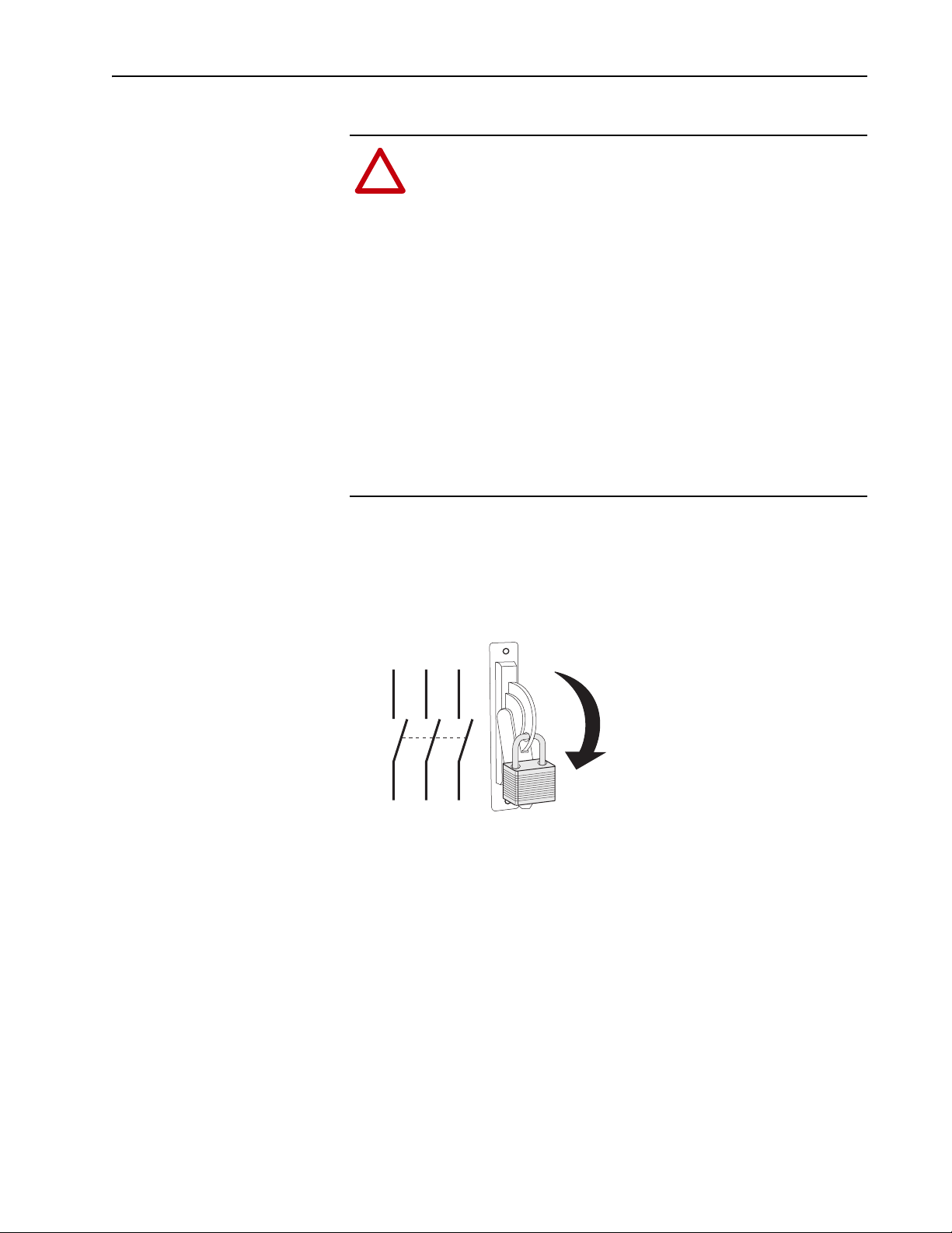
1. Turn off and lock out input power. Wait five minutes.
2. Verify that there is no voltage at the drive’s input power terminals.
3. Measure the DC bus voltage at the DC+ & DC- terminals on the Power
Terminal Block. The voltage must be zero.
L1 L2 L3
I
O
Page 4
4 Stegmann Feedback Option Board for PowerFlex® 700S Drives
Step 2: Remove the Cover(s) from the Drive
The steps for removing the covers of the drive are different depending on
the size of the drive. Refer to the appropriate instructions:
• Refer to Frame 1 - 6 Size Drives with Phase I Control
• Refer to Frame 1 - 6 Size Drives with Phase II Control
below.
on page 5
• Refer to Frame 9 Size Drives on page 5
• Refer to Frame 10 - 14 Size Drives on page 5
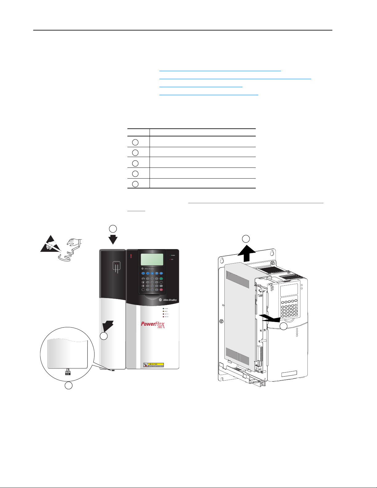
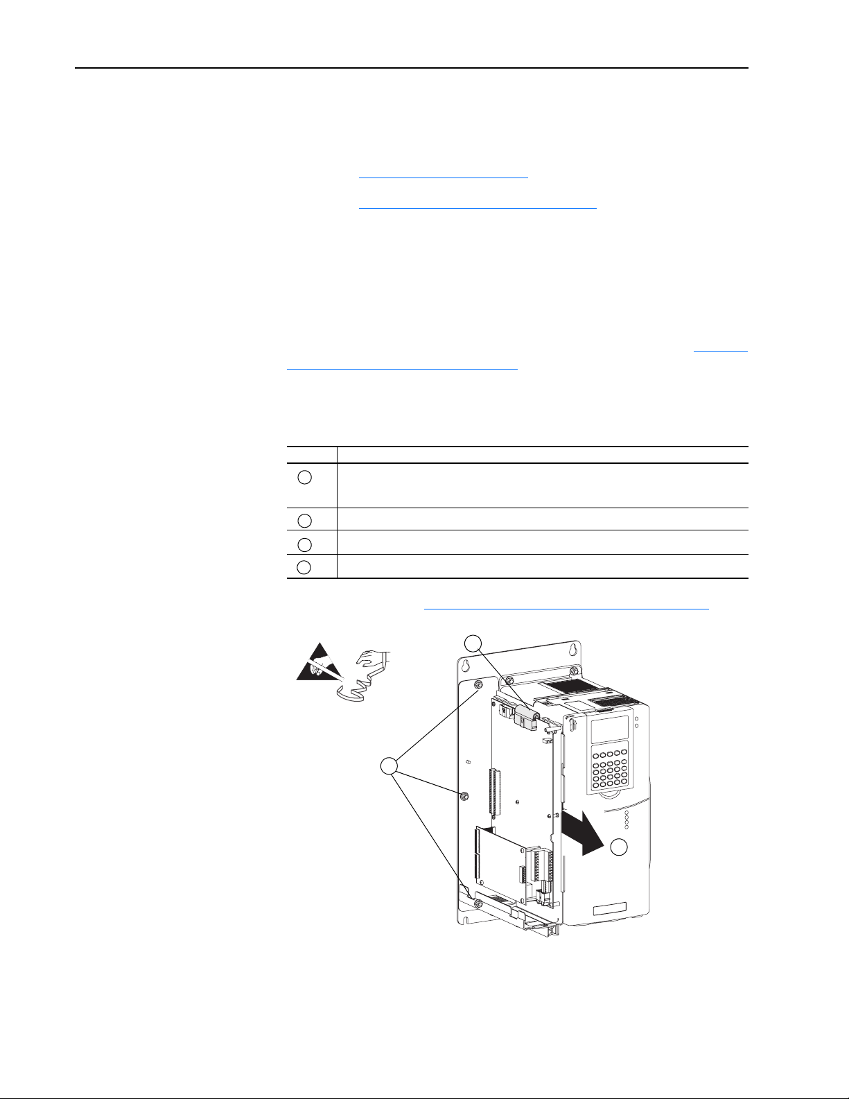
Frame 1 - 6 Size Drives with Phase I Control
Task Description
A
Loosen the captive screw.
B
Push down on the front cover.
C
Pull the front cover away from the assembly.
D
Pull the side cover forward.
E
Lift the side cover off of the control assembly.
Continue with Step 3: Remove the Control Assembly from the Drive on
page 6.
B
=
DRIVE
DRIVE
R
e
o
m
e
v
L
n
a
g
E
x
it
S
.
.T
.M
.R
.A
a
n
/ M
A
u
ENABLE
SYNCHLINK
Esc
Alt
Sel
7 8 9
4 5 6
1 2 3
.
0 +/-
Exp
to
Jog
Param #
E
D
C
A
Page 5
Stegmann Feedback Option Board for PowerFlex® 700S Drives 5
Frame 1 - 6 Size Drives with Phase II Control
Frame Action
1 - 4 Locate the slot in the upper left corner (as shown below). Slide the locking tab up and swing
the cover open. Special hinges allow the cover to move away from drive and lay on top of an
adjacent drive (if present).
5 Slide the locking tab up, loosen the right-hand cover screw and remove the cover.
6 Loosen the two screws at bottom of the drive cover. Carefully slide the bottom cover down
and out. Loosen the two screws at top of cover and remove the cover.
Continue with Step 3: Remove the Control Assembly from the Drive on
page 6.
=
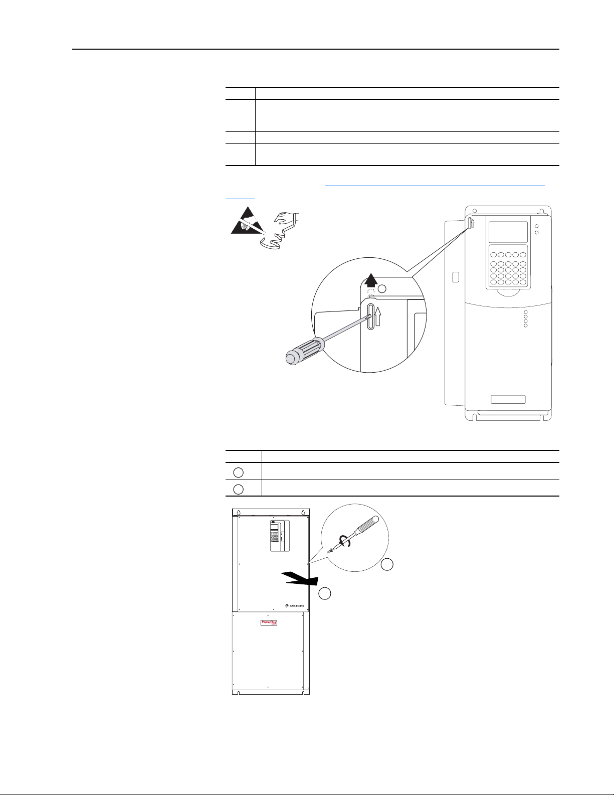
Frame 9 Size Drives
Task Action
A
Remove the eight POZIDRIV screws that secure the power (top) cover to the drive.
B
Remove the power (top) cover.
Frame 1-4 Shown
The proper tightening
torque for reassembly
is 20 lb.•in.
8 Screws
B
Frame 10 - 14 Size Drives
Open the door of the drive enclosure containing the control frame.
A
Page 6
6 Stegmann Feedback Option Board for PowerFlex® 700S Drives
Step 3: Remove the Control Assembly from the Drive
The steps to remove the control assembly from the drive are different for
drives with Phase I control versus drives with Phase II control. Refer to the
appropriate instructions:
• Refer to Drives with Phase I Control
• Refer to Drives with Phase II Control
below.
on page 7.
Drives with Phase I Control
This step is necessary only when another drive or panel component blocks
access to the control assembly on frame 1 - 6 drives with Phase I control.
Avoid removing the control assembly if possible. If you do not need to
remove the control assembly from the drive, continue with Step 4: Remove
the Feedback Option Board on page 9.
Important:Before removing connections and wires, mark the connections
and wires to avoid incorrect wiring during assembly.
Task Description
Unplug the I/O and SynchLink cables from the main control board, unplug feedback wiring
A
from the MDI Option board (if present), and unplug the communication cables from
DriveLogix controller (if present).
B
Unplug the ribbon cable.
C
Remove the three M5 nuts that secure the control assembly to the drive chassis.
D
Remove the control assembly from the drive.
Continue with Step 4: Remove the Feedback Option Board
B
=
C
Proper tightening
torque for reassembly
is 18 lb.•in.
D
on page 9.
Page 7

Stegmann Feedback Option Board for PowerFlex® 700S Drives 7
Drives with Phase II Control
It is necessary to remove the Phase II control assembly from the drive
before removing the covers.
ATTENTION: Hazard of permanent eye damage exists when
using optical transmission equipment. This product emits intense
!
light and invisible radiation. Do not look into fiber-optic ports or
fiber-optic cable connectors.
Important:Before removing connections and wires, mark the connections
and wires to avoid incorrect wiring during assembly.
Frame 1-6 Size Drives
Task Action
Unplug any fiber optic ControlNet and SynchLink cables and I/O cables from the control
A
assembly.
B
Disconnect the communications cables at the ends that connect to the main control board.
C
Loosen the screws on the face of the cassette.
D
Remove the cassette from the drive.
Continue with Remove the Cassette Covers on Drives with Phase II Control
(All Drive Sizes) on page 9
=
C
B
BR1
B
R
2
D
C
+
D
C
-
PE
U/T1
V/T2
W/T3
R/L1
L2
D
Page 8

8 Stegmann Feedback Option Board for PowerFlex® 700S Drives
Frame 9-14 Size Drives
Task Description
A
Unplug any fiber optic ControlNet and SynchLink cables from the control assembly.
Unplug any remaining I/O and communications cables from the control assembly and set them
B
aside.
C
Loosen the captive screw.
D
Swing the control assembly away from the control frame.
E
Loosen the screws on the face of the cassette.
F
Remove the cassette from the drive.
Continue with Remove the Cassette Covers on Drives with Phase II Control
(All Drive Sizes) on page 9
=
D
C
F
E
Page 9

Stegmann Feedback Option Board for PowerFlex® 700S Drives 9
Remove the Cassette Covers on Drives with Phase II Control (All Drive Sizes)
Task Description
Loosen the screws on the face of the front cover and remove the cover.
A
Loosen the screws on the side of the rear cover and remove the cover.
B
A
Proper tightening torque
for reassembly is 6 lb.•in.
=
B
Step 4: Remove the Feedback Option Board
=
Task Description
Remove the screws that secure the feedback option board to the control assembly.
A
Remove the feedback option board and through-board pin connectors from the main
B
control board.
Remove the standoffs from the main control board (drives with Phase I control only).
C
B
A
Note: Phase I shown.
TIP: Use packing material from new Stegmann Feedback option board to
return the replaced Stegmann Feedback option board.
C
Page 10

10 Stegmann Feedback Option Board for PowerFlex® 700S Drives
Step 5: Install the Feedback Option Board
The steps to install the Feedback option board are different for drives with
Phase I control versus drives with Phase II control. Refer to the appropriate
instructions:
• Refer to Drives with Phase I Control
• Refer to Drives with Phase II Control
below.
on page 11.
Drives with Phase I Control
Important:Do not use a screwdriver to pry the P1 terminal plug from the
circuit board. This may damage the plug.
Task Description
Remove the P1 terminal block from the Feedback option board. (It is much easier to
A
remove before the board is installed.)
Install and tighten the stand-offs (min/max 7 in.•lb. / 10 in.•lb.).
B
Insert the short pins
C
mating connectors on the main control board.
Important: The end with short pins must plug into the main control board.
Plug the mating connectors of the Feedback option board onto the long pins
D
through-board pin connectors.
Important: The end with longer pins must plug into the Feedback option board.
Secure board to stand-offs using the screws with the captive lock washers. Tighten the
E
screws using a Phillips screwdriver (min/max 6 in.•lb. / 8 in.•lb.).
of through-board pin connectors (part number 313611) into the
of
Important: For Phase I drives, use the stacker
connectors with part number 313611.
Important: The end with longer pins must plug
into the Stegmann Feedback option board.
=
E
Note: If the option board is not fully seated against the stand-off and is warped, either the
wrong stacker connector is used or the stacker connector is incorrectly installed.
Continue with Step 6: Install the Phase I Control Assembly
Important: The end with shorter
the main control board.
C
D
C
D
.
pins must plug into
B
Page 11

Stegmann Feedback Option Board for PowerFlex® 700S Drives 11
Drives with Phase II Control
Important:Do not use a screwdriver to pry the P1 terminal plug from the
circuit board. This may damage the plug.
Task Description
Remove the P1 terminal block from the Stegmann Feedback option board. (It is much
A
easier to remove before the board is installed.)
Insert the short pins
B
the mating connectors on the main control board.
Important: The end with short pins must plug into the main control board.
Plug the mating connectors of the Feedback option board onto the long pins
C
through-board pin connectors.
Important: The end with longer pins must plug into the Feedback option board.
Secure the board to the stand-offs using the screws with captive lock washers (supplied
D
with this kit). Tighten the screws with a Phillips® screwdriver (min/max 6 in.-lb. / 8 in.-lb.).
Note: If the option board is not fully seated against the stand-off and is warped, either the
wrong stacker connector is used or the stacker connector is incorrectly installed.
Continue with Step 7: Wire the Stegmann Feedback Option Board to an
Encoder on page 12.
of the through-board pin connectors (part number 320669-Q04) into
of
Important: For Phase II drives, use the stacker
connectors with part number 320669-Q041.
Step 6: Install the Phase I Control Assembly
=
B
Important: The end with longer pins must plug
into the Stegmann Feedback option board.
The procedure for installing the control assembly on drives with Phase I
control is the reverse of removal. Refer to Step 3: Remove the Control
Assembly from the Drive on page 6.
Important: The end with
shorter pins must plug into
the main control board.
D
C
D
D
When you have completed installing the control assembly on a drive with
Phase I control, continue with Step 7: Wire the Stegmann Feedback Option
Board to an Encoder on page 12.
Page 12

12 Stegmann Feedback Option Board for PowerFlex® 700S Drives
Step 7: Wire the Stegmann Feedback Option Board to an Encoder
Terminal block P1 contains connection points for a Stegmann Hiperface®
encoder. This terminal block resides on the Hi-Resolution Encoder
Feedback Option board.
Hiperface® is a registered trademark of Stegmann Inc.
TIP: Remember to route wires through the sliding access
panel at the bottom of the Control Assembly.
12 3456 78 9101112
Terminal Signal Description
12 POWER COMMON Power supply for encoder
11 POWER
10 REFSIN Negative Sine signal.
9 +SIN Positive Sine signal.
8 REFCOS Negative Cosine signal.
7 +COS Positive Cosine signal.
6 SHIELD Connection point for encoder
5SHIELD
4 N/C Not connected.
3N/C
2 DATA+ (RS 485) Positive DH485 terminal.
1 DATA- (RS 485) Negative DH485 terminal.
interface.
cable shield.
Page 13

Stegmann Feedback Option Board for PowerFlex® 700S Drives 13
Table A Recommended Cables
If you are using this motor and feedback
device: Use this cable: See this wiring diagram:
Allen-Bradley 1326AB-BXXXX-21ML, and
-21MKXL motors with embedded Stegmann
rotary encoder
Allen-Bradley 1326AB-BXXXX-M2L, -M2KXL,
-S2L, and -S2KXL motors with embedded
Stegmann rotary encoder
Allen-Bradley MPL-A5xx and all MPL-Bxxx
motors with embedded Stegmann rotary
encoder
Allen-Bradley 1326AB-BXXXX-M2L, -M2KXL,
-S2L, and -S2KXL motors with embedded
Stegmann rotary encoder
Allen-Bradley MPL-A5xx and all MPL-Bxxx
motors with embedded Stegmann rotary
encoder
Allen-Bradley MPL-A3xx - MPL-A45xx and all
MPG series motors with embedded Stegmann
rotary encoder
Allen-Bradley MPL-A3xx - MPL-A45xx and all
MPG series motors with embedded Stegmann
rotary encoder
HPK-Series motors with embedded Stegmann
rotary encoder
Any other motor with external Stegmann
SHS-170 rotary encoder
Any other motor with external Stegmann
SCS-60, SCS-70, SCM-60 or SCM-70, SRS-50,
SRS-60, SRM-60, SRM-60, SRS-25 or SRM-25
rotary encoder
Any other motor with external Stegmann
SCS-Kit 101 or SCK-Kit 101 rotary encoder
Any other motor with external Stegmann
SRS660 rotary encoder
Allen-Bradley 1326-CECU-XXL-XXX Figure 1 on page -14
Allen-Bradley 2090-CDNFDMP-SXX Figure 2 on page -14
Allen-Bradley 2090-CDNFDMP-SXX Figure 2 on page -14
Allen-Bradley 2090-XXNFMP-SXX Figure 3 on page -14
Allen-Bradley 2090-XXNFMP-SXX Figure 3 on page -14
Allen-Bradley 2090-XXNFMP-SXX Figure 4 on page -15
Allen-Bradley 2090-UXNFDMP-SXX Figure 5 on page -15
Allen-Bradley 2090-XXNFMF-SXX Figure 6 on page -15
Stegmann shielded twisted-pair cable with 12-pin DIN style connector Figure 7 on page -16
Stegmann shielded twisted-pair cable with 10-pin MS style connector Figure 8 on page -16
Stegmann shielded twisted-pair cable with 8-pin Berg style connector Figure 9 on page -16
Is available only with pre-attached Stegmann shielded twisted-pair
cable of various lengths
Figure 10 on page -17
Page 14

14 Stegmann Feedback Option Board for PowerFlex® 700S Drives
Connection Examples
Figure 1 1326AB-BXXXX-21ML, and -21MKXL motors with a 1326-CECU-XXL-XXX cable
ENCODERHi-Res Feedback Option Board
A
POWER
B
POWER COMMON
C
REFSIN
D
+SIN
E
REFCOS
F
+COS
G
DATA+ (RS-485)
H
DATA- (RS-485)
I
SHIELD
OVERALL SHIELD
J
POWER COMMON
POWER
REFSIN
+SIN
REFCOS
+COS
SHIELD
SHIELD
N/C
N/C
DATA+ (RS 485)
DATA- (RS 485)
12
11
10
WH
BK
BK
9
8
7
6
5
4
3
2
1
RD
BK
BU
BK
GN
BK
WH
BK
RD
BK
BU
BK
GN
Figure 2 MPL-A5xx and all MPL-Bxxx motors or 1326AB-BXXXX-M2L, -M2KXL, -S2L, and -S2KXL motors with
2090-CDNFDMP-SXX cable
POWER COMMON
POWER
REFSIN
+SIN
REFCOS
+COS
SHIELD
SHIELD
N/C
N/C
DATA+ (RS 485)
DATA- (RS 485)
Hi-Res Feedback Option Board
12
11
10
9
8
7
6
5
4
3
2
1
WH/OR
OR
BK/WH
BK
WH/RD
RD
BU
WH/BU
GN
WH/GN
BK
BK/WH
RD
WH/RD
GN
WH/GN
OR
WH/OR
BU
WH/BU
ENCODER
A
+SIN
REFSIN
B
C
+COS
REFCOS
D
DATA+ (RS-485)
E
DATA- (RS 485)
F
POWER
N
COMMON
P
TS+
R
TS-
S
Figure 3 MPL-A5xx and all MPL-Bxxx Motor or 1326AB-BXXXX-M2L, -M2KXL, -S2L, and -S2KXL motor with
2090-XXNFMP-SXX cable
POWER COMMON
POWER
REFSIN
+SIN
REFCOS
+COS
SHIELD
SHIELD
N/C
N/C
DATA+ (RS 485)
DATA- (RS 485)
Hi-Res Feedback Option Board
12
11
10
9
8
7
6
5
4
3
2
1
WH/GY
OR
BK/WH
BK
WH/RD
RD
GN
WH/GN
BK
BK/WH
RD
WH/RD
GN
WH/GN
OR
WH/GY
ENCODER
A
+SIN
B
REFSIN
C
+COS
D
REFCOS
E
DATA+ (RS-485)
F
DATA- (RS 485)
N
POWER
P
COMMON
R
TS+
S
TS-
Note: Thermal Switch cannot be accessed using 2090-XXNFMP-SXX cable.
Page 15

Stegmann Feedback Option Board for PowerFlex® 700S Drives 15
Connection Examples
Figure 4 MPL-A3xx - MPL-A45xx and all MPG series motors with 2090-XXNFMP-SXX cable
POWER COMMON
POWER
REFSIN
+SIN
REFCOS
+COS
SHIELD
SHIELD
N/C
N/C
DATA+ (RS 485)
DATA- (RS 485)
Hi-Res Feedback Option Board
12
11
10
9
8
7
6
5
4
3
2
1
WH/GY
GY
BK/WH
BK
WH/RD
RD
GN
WH/GN
BK
BK/WH
RD
WH/RD
GN
WH/GN
GY
WH/GY
Note: Thermal Switch cannot be accessed using 2090-XXNFMP-SXX cable.
Figure 5 MPL-A3xx - MPL-A45xx and all MPG series motors with 2090-UXNFDMP-SXX cable
POWER COMMON
POWER
REFSIN
+SIN
REFCOS
+COS
SHIELD
SHIELD
N/C
N/C
DATA+ (RS 485)
DATA- (RS 485)
Hi-Res Feedback Option Board
12
11
10
9
8
7
6
5
4
3
2
1
WH/GY
GY
BK/WH
BK
WH/RD
RD
BU
WH/BU
GN
WH/GN
BK
BK/WH
RD
WH/RD
GN
WH/GN
GY
WH/GY
BU
WH/BU
ENCODER
A
+SIN
REFSIN
B
C
+COS
REFCOS
D
DATA+ (RS-485)
E
DATA- (RS 485)
F
POWER
K
COMMON
L
TS+
R
TS-
S
ENCODER
A
+SIN
REFSIN
B
C
+COS
REFCOS
D
DATA+ (RS-485)
E
DATA- (RS 485)
F
POWER
K
COMMON
L
TS+
R
TS-
S
Figure 6 HPK-Series motors with 2090-XXNFMF-SXX cable
POWER COMMON
POWER
REFSIN
+SIN
REFCOS
+COS
SHIELD
SHIELD
N/C
N/C
DATA+ (RS 485)
DATA- (RS 485)
Hi-Res Feedback Option Board
12
11
10
9
8
7
6
5
4
3
2
1
WH/GY
OR
BK/WH
BK
WH/RD
RD
GN
WH/GN
BK
BK/WH
RD
WH/RD
GN
WH/GN
OR
WH/GY
Note: Thermal Switch cannot be accessed using 2090-XXNFMP-SXX cable.
ENCODER
A
+SIN
REFSIN
B
C
+COS
REFCOS
D
DATA+ (RS-485)
E
DATA- (RS 485)
F
POWER
N
COMMON
P
TS+
R
TS-
S
Page 16

16 Stegmann Feedback Option Board for PowerFlex® 700S Drives
Connection Examples
Figure 7 Stegmann shielded twisted-pair cable with 12-pin DIN style connector
POWER COMMON
POWER
REFSIN
+SIN
REFCOS
+COS
SHIELD
SHIELD
N/C
N/C
DATA+ (RS 485)
DATA- (RS 485)
Hi-Res Feedback Option Board
12
11
10
9
8
7
6
5
4
3
2
1
BU
RD
BN
WH
BK
PK
GY
GN
Figure 8 Stegmann shielded twisted-pair cable with 10-pin MS style connector
POWER COMMON
POWER
REFSIN
+SIN
REFCOS
+COS
SHIELD
SHIELD
N/C
N/C
DATA+ (RS 485)
DATA- (RS 485)
Hi-Res Feedback Option Board
12
11
10
9
8
7
6
5
4
3
2
1
BU
RD
BN
WH
BK
PK
GY
GN
BU
PK
GN
BN
WH
GY
BK
RD
BN
GY
GN
WH
RD
BU
BK
PK
ENCODER
POWER
12
N/C
11
POWER COMMON
10
SHIELD
9
+COS
8
DATA- (RS 485)
7
REFSIN
6
+SIN
5
N/C
4
N/C
3
DATA+ (RS 485)
2
REFCOS
1
ENCODER
A
POWER
B
POWER COMMON
C
REFSIN
REFCOS
D
DATA+ (RS 485)
E
F
DATA- (RS 485)
G
+SIN
H
+COS
I
N/C
J
SHIELD
Figure 9 Stegmann shielded twisted-pair cable with 8-pin Berg style connector
POWER COMMON
POWER
REFSIN
+SIN
REFCOS
+COS
SHIELD
SHIELD
N/C
N/C
DATA+ (RS 485)
DATA- (RS 485)
Hi-Res Feedback Option Board
12
11
10
9
8
7
6
5
4
3
2
1
BU
RD
BN
WH
BK
PK
GY
GN
RD
BU
BN
BK
GY
GN
WH
PK
ENCODER
POWER
1
POWER COMMON
2
REFSIN
3
REFCOS
4
DATA+ (RS 485)
5
DATA- (RS 485)
6
+SIN
7
+COS
8
Page 17

Connection Examples
Figure 10 Pre-attached Stegmann shielded twisted-pair cable
Stegmann Feedback Option Board for PowerFlex® 700S Drives 17
Hi-Res Feedback Option Board
POWER
REFSIN
+SIN
REFCOS
+COS
SHIELD
SHIELD
N/C
N/C
12
11
10
9
8
7
6
5
4
3
2
1
POWER COMMON
DATA+ (RS 485)
DATA- (RS 485)
Step 8: Install the Phase II Control Assembly
Step 9: Install the Covers on the Drive
ENCODER
BU
RD
BN
WH
BK
PK
GY
GN
RD
BU
BN
BK
GY
GN
WH
PK
POWER
1
POWER COMMON
2
REFSIN
3
REFCOS
4
DATA+ (RS 485)
5
DATA- (RS 485)
6
+SIN
7
+COS
8
The procedure for installing the Phase II control assembly is the reverse of
removal. Refer to Step 3: Remove the Control Assembly from the Drive
page 6.
The procedure for installing the covers on all drives is the reverse of
removal. Refer to Step 2: Remove the Cover(s) from the Drive
on page 4.
on
Step 10: Document the Change
Document the option board installation on the Field Installed Options label.
Use the blank line if you are installing the Stegmann Feedback option in a
drive that was manufactured without it.
Frame 1 - 6 Size Drives
FIELD INSTALLED OPTIONS
Firmware #: Date
#: Date
Firmware
20-HIM
HIM
28-IO-
I/O
20-COMM-
COM Module
20B_-DB1-
Internal Dynamic Brake
Page 18

18 Stegmann Feedback Option Board for PowerFlex® 700S Drives
Frame 9 - 13 Size Drives
Frame 9
FIELD INSTALLED OPTIONS
Firmware #: Date
#: Date
Firmware
HIM
20-HIM
I/O
28-IO-
COM Module
20-COMM-
Internal Dynamic Brake
20B_-DB1-
FIELD INSTALLED OPTIONS
Firmware #: Date
#: Date
Firmware
20-HIM
HIM
28-IO-
I/O
20-COMM-
COM Module
20B_-DB1-
Internal Dynamic Brake
Frames 10 - 13
FIELD INSTALLED OPTIONS
Firmware #: Date
#: Date
Firmware
HIM
20-HIM
I/O
28-IO-
COM Module
20-COMM-
Internal Dynamic Brake
20B_-DB1-
FIELD INSTALLED OPTIONS
Firmware #: Date
#: Date
Firmware
20-HIM
28-IO20-COMM20B_-DB1-
HIM
I/O
COM Module
Internal Dynamic Brake
Specifications
Stegmann Feedback Option Board Specifications
Consideration Description
Encoder Voltage Supply 11.5V dc @ 130 mA
Stegmann Feedback Sine/Cosine 1V P-P Offset 2.5
Maximum Cable Length 90m (295 ft)
Maximum Frequency
(Encoder Speed)
12.5 μs/cycle
(4687.5 RPM for encoders with 1024 sine cycles per revolution)
(9375 RPM for encoders with 512 sine cycles per revolution)
RS-485 Interface The Stegmann Feedback Option board obtains the following
information via the Hiperface RS-485 interface shortly after
power-up:
• Address
• Command Number
• Mode
• Number of turns
• Number of Sine/Cos cycles
• Checksum
Customer-I/O plug (P1) Allen-Bradley PN: S94262912
Weidmuller PN: BL3.50/90/12BK
Supported Encoders
Table B below specifies which encoders are supported by the 700S
Hi-Resolution Stegmann Encoder Feedback Option module.
Important:Please note that encoders must be ordered as “Single Ended”.
This will ensure that the RS-485 channel has the proper
termination network installed at the factory.
Page 19

Stegmann Feedback Option Board for PowerFlex® 700S Drives 19
Table B Supported Stegmann Encoders
Model Resolution Comment
SINCOS® SCS-60, SCS-70,
SCM-60, and SCM-70
SINCOS® SCS-KIT-101 and
SCM-KIT-101
SINCOS® SRS-50, SRS-60,
SRM-50, and SRM-60
SINCOS® SRS/M 25 1024 sine cycles per revolution SRS25 and SRM25 have built-in
SINCOS® SRS660 1024 sine cycles per revolution Hollow-shaft up to 14 mm diameter
SINCOS® SHS-170 512 sine cycles per revolution. While the software supports this
SINCOS®, SINCODER® and LINCODER® are registered trademarks of Stegmann Inc.
512 sine cycles per revolution. SCM-60 and SCM-70 have built-in
mechanical turns counter.
1024 sine cycles per revolution. SCM-60 and SCM-70 have built-in
mechanical turns counter.
1024 sine cycles per revolution. SRM-50 and SRM-60 have built-in
mechanical turns counter.
mechanical turns counter. IP65
Protection Class. Size 25 square
flange mounting.
encoder, the SHS-170 draws
excessive current and should only be
used with an external power supply.
Page 20

A
A
www.rockwellautomation.com
Power, Control and Information Solutions Headquarters
mericas: Rockwell Automation, 1201 South Second Street, Milwaukee, WI 53204 USA, Tel: (1) 414.382.2000, Fax: (1) 414.382.4444
Europe/Middle East/Africa: Rockwell Automation, Vorstlaan/Boulevard du Souverain 36, 1170 Brussels, Belgium, Tel: (32) 2 663 0600, Fax: (32) 2 663 0640
sia Pacific: Rockwell Automation, Level 14, Core F, Cyberport 3, 100 Cyberport Road, Hong Kong, Tel: (852) 2887 4788, Fax: (852) 2508 1846
Publication 20D-IN001G-EN-P - May 2008 P/N 317680-P05
Superseeds 20D-IN001F-EN-P April 2006 Copyright © 2008 Rockwell Automation, Inc. All rights reserved. Printed in USA.
 Loading...