

Page 1
Installation Instructions
PowerFlex 700H and 700S AC Drives Frame 11 Main Fan
Capacitor Replacement Kit
ATTENTION: The sheet metal cover and mounting screws on the ASIC
Board located on the power structure are energized at (-) DC bus potential
high voltage. Risk of electrical shock, injury, or death exists if someone
comes into contact with the assembly.
ATTENTION: This drive contains ESD (Electrostatic Discharge) sensitive
parts and assemblies. Static control precautions are required when
installing, testing, servicing or repairing this assembly. Component
damage may result if ESD control procedures are not followed. If you are
not familiar with static control procedures, reference A-B publication
8000-4.5.2, “Guarding Against Electrostatic Damage” or any other
applicable ESD protection guide.
ATTENTION: Only qualified personnel familiar with adjustable frequency
AC drives and associated machinery should perform maintenance/repair of
the system. Failure to comply may result in personal injury and/or
equipment damage.
ATTENTION: The following information is merely a guide for proper
installation. Rockwell Automation cannot assume responsibility for the
compliance or the noncompliance to any code, national, local or otherwise
for the proper installation of this drive or associated equipment. A hazard
of personal injury and/or equipment damage exists if codes are ignored
during installation.
PFLEX-IN026A-EN-P
Page 2
PowerFlex 700H and 700S AC Drives Frame 11 Main Fan Capacitor Replacement Kit
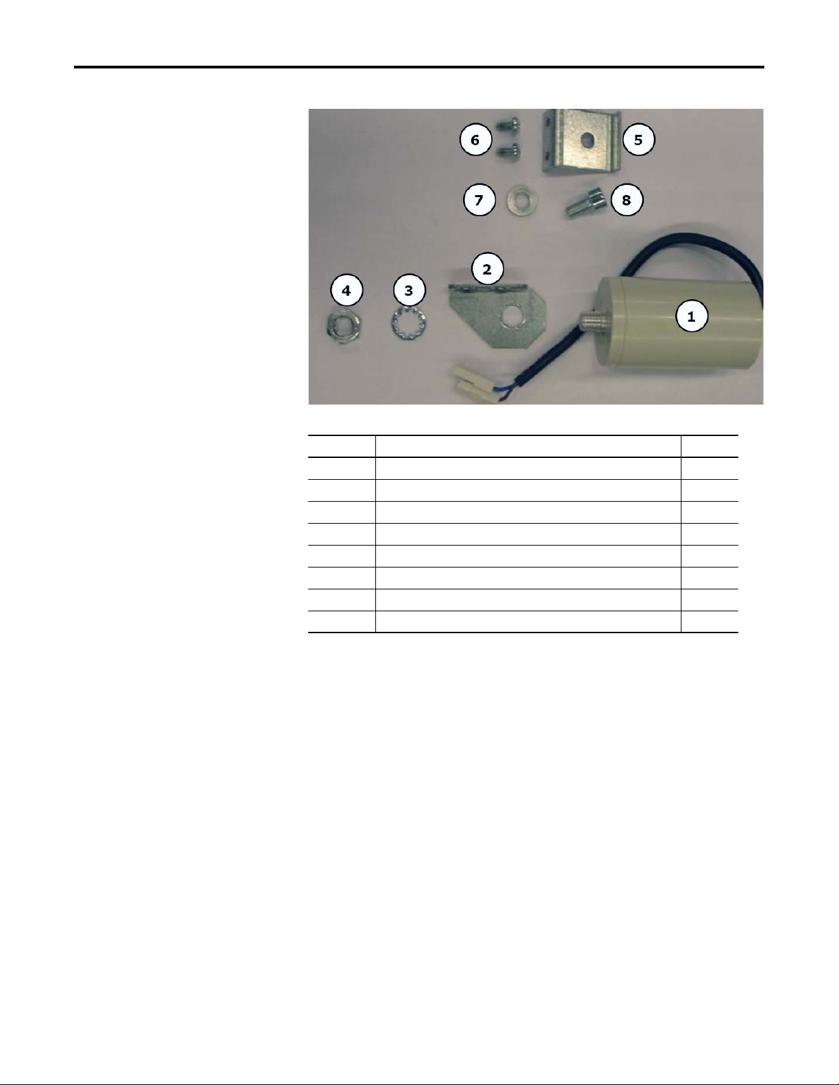
What This Kit Includes
Photo ID# Part Description Quantity
1Fan capacitor 1
2 Fan capacitor bracket 1
3 M12 lock washer (for fan capacitor bracket) 1
4 M12 fastening nut (for fan capacitor bracket) 1
5 Adapter bracket 1
6 M5 x 10 mm POZIDRIV screw (for adapter bracket) 2
7 Spring washer (for adapter bracket) 1
8 M8 x 12 mm hexagonal socket screw (for adapter bracket) 1
Tools That You Need
• #2 POZIDRIV® screwdriver
• T20 hexalobular screwdriver
• 17 and 19 mm wrench
• Hexagonal head screwdriver
• Wire cutter
• Nose pliers
POZIDRIV® is a registered trademark of the Phillips Screw Company
2 Rockwell Automation Publication PFLEX-IN026A-EN-P - July 2011
Page 3
PowerFlex 700H and 700S AC Drives Frame 11 Main Fan Capacitor Replacement Kit
What You Need to Do
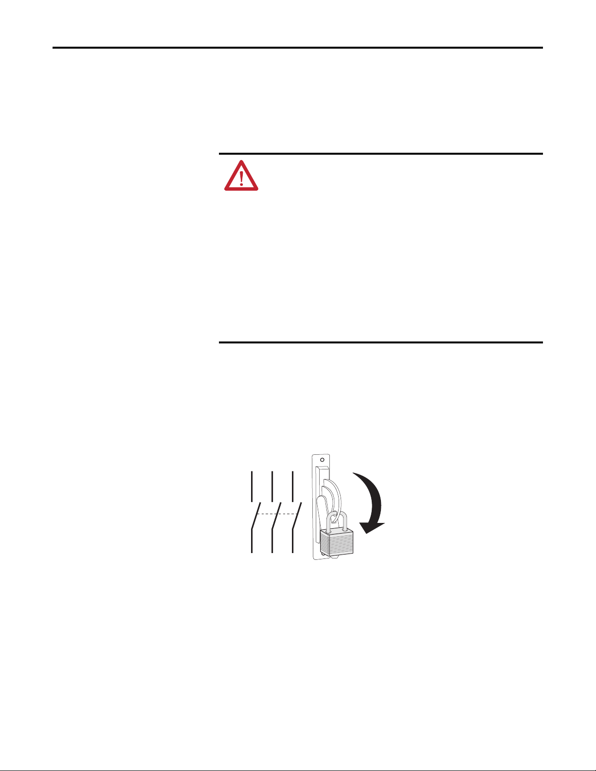
Step: 1 Remove Power
from the Drive
• Step 1: Remove power from the drive
• Step 2: Remove the protective covers
• Step 3: Remove the existing fan capacitor
• Step 4: Install the new fan capacitor and bracket
ATTENTION: To avoid an electric shock hazard, verify that the voltage on
the bus capacitors has discharged before performing any work on the
drive. Check the DC bus voltage at the power terminal block by measuring
between the +DC and -DC terminals, between the +DC terminal and the
chassis, and between the -DC terminal and the chassis. The voltage must
be zero for all three measurements.
Remove power before making or breaking cable connections. When you
remove or insert a cable connector with power applied, an electrical arc
may occur. An electrical arc can cause personal injury or property damage
by:
• sending an erroneous signal to your system’s field devices, causing
unintended machine motion
• causing an explosion in a hazardous environment
Electrical arcing causes excessive wear to contacts on both the module
and its mating connector. Worn contacts may create electrical resistance.
1. Turn off and lock out input power. Wait fifteen minutes.
2. Verify that there is no voltage at the drive’s input power terminals.
3. Check the DC bus voltage at the power terminal block by measuring
between the +DC and -DC terminals, between the +DC terminal and the
chassis, and between the -DC terminal and the chassis. The voltage must
be zero for all three measurements.
L1 L2 L3
I
O
Rockwell Automation Publication PFLEX-IN026A-EN-P - July 2011 3
Page 4
PowerFlex 700H and 700S AC Drives Frame 11 Main Fan Capacitor Replacement Kit
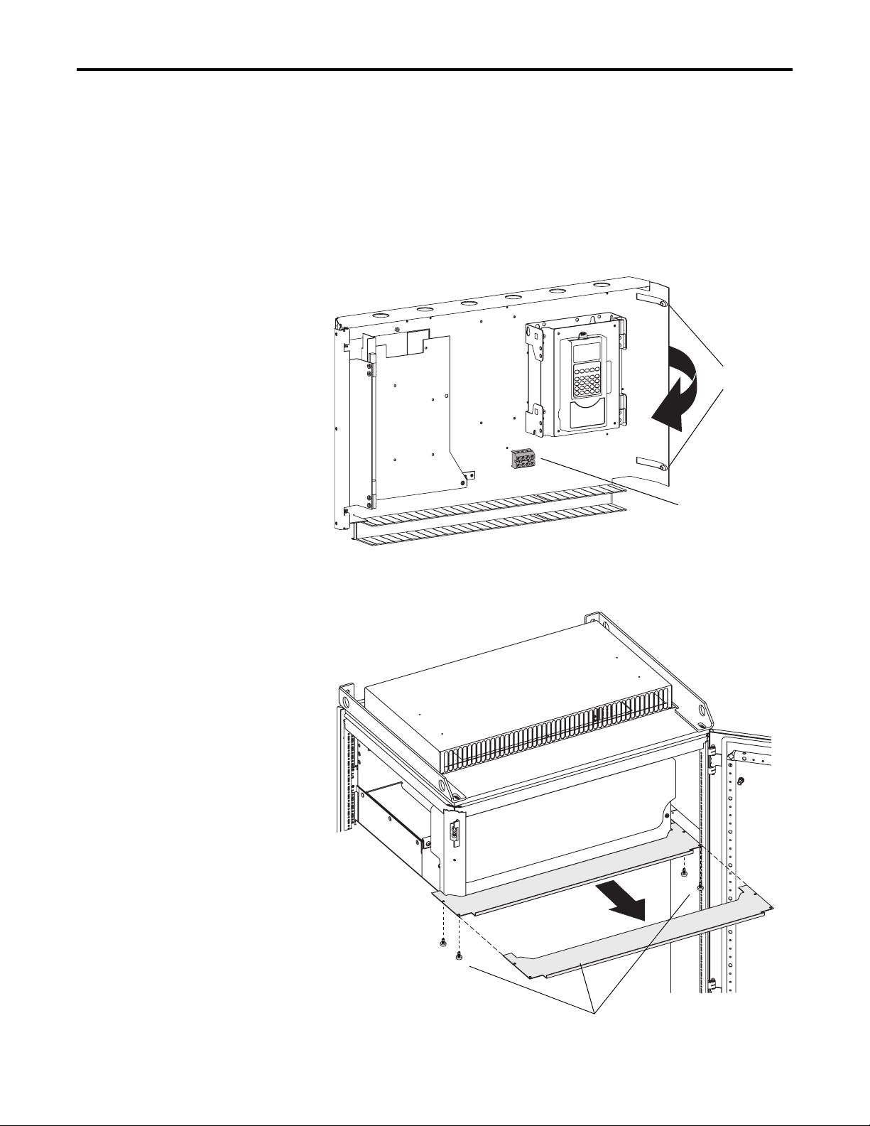
Step: 2 Remove the
Protective Covers
You must first move the control frame and remove the air flow plate from the
drive in order to access the protective covers on the drive.
1. If you are moving the control frame on a DC input drive with a precharge
interlock, disconnect the input wiring to the X50 terminal block on the
control frame.
2. Loosen the two hexalobular screws that secure the control frame to the
enclosure and swing the control frame away from the drive.
Loosen two
screws and
swing control
frame out
If present, remove
wiring from X50
terminal block
3. Remove the four hexalobular screws that secure the air flow plate to the
drive enclosure and slide the plate off the drive.
Remove four screws and plate
4 Rockwell Automation Publication PFLEX-IN026A-EN-P - July 2011
Page 5

PowerFlex 700H and 700S AC Drives Frame 11 Main Fan Capacitor Replacement Kit
4. Remove the four M5 x 16 mm POZIDRIV screws that secure the top
and bottom protective covers to the main front protective cover, then
remove the top and bottom protective covers. Tightening torque for reassembly is 1.5 N
•m (13.3 lb•in).
5. Remove the four M5 x 10 mm POZIDRIV screws, which secure the
main front protective cover to the drive, then remove the protective
cover. Tightening torque for re-assembly is 1.5 N
Remove screws and covers
•m (13.3 lb•in).
Rockwell Automation Publication PFLEX-IN026A-EN-P - July 2011 5
Page 6

PowerFlex 700H and 700S AC Drives Frame 11 Main Fan Capacitor Replacement Kit
Step: 3 Remove the
Existing Fan Capacitor
Remove wires from fan fuse holder Cut cable tieCut cable tie
1. Disconnect the fan signal connector from the front of the drive chassis.
2. If replacing the fan capacitor on the V phase, loosen the screws that secure
the wires to both ends of the fan fuse holder and remove the wires.
3. Cut the cable ties that secure the fan signal and fan fuse wires to the fan
capacitor.
Disconnect fan signal connectorDisconnect fan signal connector
6 Rockwell Automation Publication PFLEX-IN026A-EN-P - July 2011
Page 7

PowerFlex 700H and 700S AC Drives Frame 11 Main Fan Capacitor Replacement Kit
4. Disconnect the main fan motor power supply connector from the bottom
of the fan inverter.
5. Remove the four M5 x 10 mm POZIDRIV screws that secure the fan
inverter assembly to the drive chassis. Tightening torque for re-assembly is
•m (35 lb•in).
4 N
Bottom view
of power structure
Remove screws
Disconnect fan
motor power
supply cable
Remove screws
Rockwell Automation Publication PFLEX-IN026A-EN-P - July 2011 7
Page 8

PowerFlex 700H and 700S AC Drives Frame 11 Main Fan Capacitor Replacement Kit
6. Remove the motor output cables from the appropriate terminal (U/T1,
V/T2, W/T3). Tightening torque for re-assembly is 40 N
7. Remove the M10 x 20 mm hexagonal bolts and washers that secure the
motor output terminal to standoffs on the drive chassis and move the
terminal so that the fan inverter assembly can easily be removed from the
drive chassis. Tightening torque for re-assembly is 20 N
•m (354 lb•in).
•m (177 lb•in).
Remove bolts and washers and remove terminal
Remove the motor output cables
8 Rockwell Automation Publication PFLEX-IN026A-EN-P - July 2011
Page 9

PowerFlex 700H and 700S AC Drives Frame 11 Main Fan Capacitor Replacement Kit
8. Slide the fan inverter assembly out of the drive chassis.
IMPORTANT
Take care to not damage the output transformer when removing or
installing the fan inverter assembly.
9. Cut the cable ties that secure the fan capacitor wires to the inverter
assembly.
10. Disconnect the fan capacitor wire connectors marked “Brown” and “Blue”
11. Unscrew and remove the fan capacitor from the inverter assembly. Note,
for the V phase fan inverter assembly, the fuse holder and bracket to which
it is secured must be saved for reuse.
Disconnect connectors
marked Brown” and “Blue”
Cut cable tiesUnscrew fan capacitor
Output transformer
=
Rockwell Automation Publication PFLEX-IN026A-EN-P - July 2011 9
Page 10

PowerFlex 700H and 700S AC Drives Frame 11 Main Fan Capacitor Replacement Kit
Step: 4 Install the New
Fan Capacitor and Bracket
1. Secure the new fan capacitor adapter bracket to the fan inverter assembly
using the new M8 x 16 mm hexagonal socket screw and washer provided in
the kit. For the V phase fan inverter assembly, the fuse holder and bracket
to which it is secured must be installed on top of the new adapter bracket
(see illustration below). Tightening torque is 12 N
Phase U and W fan inverter assemblies
Phase V fan inverter assembly
•m (106 lb•in).
New adapter bracket
Existing bracket (and
fuse holder - not shown)
New adapter bracket
2. Secure the new fan capacitor to the new fan capacitor bracket using the
M12 nut and lock washer provided in the kit. Tightening torque is 5 N
•in).
(44 lb
Nut Washer Bracket Capacitor
•m
Bracket
front view
10 Rockwell Automation Publication PFLEX-IN026A-EN-P - July 2011
Page 11

PowerFlex 700H and 700S AC Drives Frame 11 Main Fan Capacitor Replacement Kit
3. Secure the new fan capacitor bracket assembly to the fan inverter assembly
using the two M5 x 10 mm POZIDRIV screws provided in the kit.
Tightening torque is 4 N
•m (35 lb•in).
Secure capacitor bracket assembly to fan
inverter assembly using two screws provided
4. Install the fan inverter assembly in the reverse order of removal as detailed
in Step 3
Remove the Existing Fan Capacitor on page 6.
Rockwell Automation Publication PFLEX-IN026A-EN-P - July 2011 11
Page 12

U.S. Allen-Bradley Drives Technical Support - Tel: (1) 262.512.8176, Fax: (1) 262.512.2222, E-mail: support@drives.ra.rockwell.com, Online: www.ab.com/support/abdrives
*
PN-117697*
www.rockwellautomation.com
Power, Control and Information Solutions Headquarters
Americas: Rockwell Automation, 1201 South Second Street,
/
Middle East/Africa: Rockwell Automati
Europe
Asia Pacific: Rockwell Automation, Level 14, Core F, Cyberport 3, 100 Cyberport Road, Hong Kong, Tel: (852) 2887 4788, Fax: (852) 2508 1846
on,
Milwaukee, WI 53204-2496 USA,
Pegasus Park, De Kleetlaan 12a,
Tel:
(1) 414.382.2000, Fax: (1) 414.382.4444
1831 Diegem, Belgium,
Tel: (32) 2 663 0600, Fax: (32) 2 663 0640
PN-117697
Publication PFLEX-IN026A-EN-P – July 2011
Copyright © 2011 Rockwell Automation, Inc. All rights reserved. Printed in USA.
 Loading...