

Page 1
Installation Instructions
PowerFlex 700 Adjustable Frequency AC Drive – Frames 7…10
This document explains the 5 BASIC STEPS needed to install and perform a
Basic Start-Up of the PowerFlex 700 AC drive. A Human Interface Module
(HIM) is required to perform the Basic Start-Up routine covered in this manual.
The information provided is intended for qualified installers only.
Additional Resources
These documents contain additional information concerning related products
from Rockwell Automation.
Resource Description
PowerFlex 700 Standard Control User Manual, publication
20B-UM001
PowerFlex 700 Vector Control User Manual (v4.001 & up),
publication 20B-UM002
PowerFlex 700 AC Drive Technical Data, publication
20B-TD001
PowerFlex Comm Adapter Manuals, publication
20COMM-UM…
PowerFlex 70 and PowerFlex 700 Reference Manual,
publication PFLEX-RM001
PowerFlex 70 Enhanced Control and PowerFlex 700 Vector
Control Reference Manual, publication PFLEX-RM004
Wiring and Grounding Guidelines for Pulse Width
Modulated (PWM) AC Drives, publication DRIVES-IN001
Safety Guidelines for the Application, Installation and
Maintenance of Solid State Control, publication SGI-1.1
Guarding Against Electrostatic Damage, publication
8000-4.5.2
Product Certifications website, http://ab.com
Provides detailed information on:
• Parameters and programming
• Faults, alarms, and troubleshooting
This publication provides detailed drive specifications,
option specifications and input protection device ratings.
These publications provide information on configuring,
using, and troubleshooting PowerFlex communication
adapters.
These publications provide detailed application specific
information for programming and configuring the
PowerFlex 700 drive.
Provides basic information needed to properly wire and
ground PWM AC drives.
Provides general guidelines for the application,
installation, and maintenance of solid-state control.
Provides practices for guarding against Electrostatic
damage (ESD)
Provides declarations of conformity, certificates, and
other certification details.
You can view or download publications at
http://www.rockwellautomation.com/literature/
. To order paper copies of
technical documentation, contact your local Allen-Bradley distributor or
Rockwell Automation sales representative.
Page 2

PowerFlex 700 Adjustable Frequency AC Drive – Frames 7…10
Allen-Bradley Drives Technical Support
Use the contacts below for PowerFlex 700 technical support including spare parts
information.
Online at… By Email at… By Telephone at…
www.ab.com/support/abdrives support@drives.ra.rockwell.com 262-512-8176
Documentation in Other Languages
User Manuals are available in multiple languages at:
http://www.rockwellautomation.com/literature
Select publication language and type “20B-UM002” in the search field.
.
2 Rockwell Automation Publication 20B-IN014H-EN-P - June 2013
Page 3

PowerFlex 700 Adjustable Frequency AC Drive – Frames 7…10
Table of Contents
Catalog Number Explanation . . . . . . . . . . . . . . . . . . . . . . . . . . . . . . . . . . . . . . . . . . . . . 4
Step 1: Read the Precautions and General Information . . . . . . . . . . . . . . . . . . . . . 5
EMC Compliance . . . . . . . . . . . . . . . . . . . . . . . . . . . . . . . . . . . . . . . . . . . . . . . . . . . . . . . 7
Component Locations . . . . . . . . . . . . . . . . . . . . . . . . . . . . . . . . . . . . . . . . . . . . . . . . . . . 8
Step 2: Lifting and Mounting the Drive. . . . . . . . . . . . . . . . . . . . . . . . . . . . . . . . . . 12
Lifting . . . . . . . . . . . . . . . . . . . . . . . . . . . . . . . . . . . . . . . . . . . . . . . . . . . . . . . . . . . . . . . . .12
Environment . . . . . . . . . . . . . . . . . . . . . . . . . . . . . . . . . . . . . . . . . . . . . . . . . . . . . . . . . . .14
Minimum Mounting Clearances & Heat Dissipation. . . . . . . . . . . . . . . . . . . . . . .14
Removing the Frame 7 Cover . . . . . . . . . . . . . . . . . . . . . . . . . . . . . . . . . . . . . . . . . . . . 14
Dimensions . . . . . . . . . . . . . . . . . . . . . . . . . . . . . . . . . . . . . . . . . . . . . . . . . . . . . . . . . . . .15
Step 3: Wire the Drive . . . . . . . . . . . . . . . . . . . . . . . . . . . . . . . . . . . . . . . . . . . . . . . . 29
Special Considerations . . . . . . . . . . . . . . . . . . . . . . . . . . . . . . . . . . . . . . . . . . . . . . . . . .29
Cable Types Acceptable for 200…600 Volt Installations . . . . . . . . . . . . . . . . . . . .31
Single-Phase Input Power – Frame 7 Only. . . . . . . . . . . . . . . . . . . . . . . . . . . . . . . . .32
Power Terminal Blocks . . . . . . . . . . . . . . . . . . . . . . . . . . . . . . . . . . . . . . . . . . . . . . . . . . 33
Fan Circuit Power Supply. . . . . . . . . . . . . . . . . . . . . . . . . . . . . . . . . . . . . . . . . . . . . . . .35
Additional Frame 10 Wiring Requirement for IP00 AC Input Drives. . . . . . . .38
DC Link Chokes – Frames 8…10. . . . . . . . . . . . . . . . . . . . . . . . . . . . . . . . . . . . . . . . . 38
Auxiliary Control Power Supply. . . . . . . . . . . . . . . . . . . . . . . . . . . . . . . . . . . . . . . . . .39
General Grounding Requirements. . . . . . . . . . . . . . . . . . . . . . . . . . . . . . . . . . . . . . . .40
Motor Overload Protection. . . . . . . . . . . . . . . . . . . . . . . . . . . . . . . . . . . . . . . . . . . . . .41
Drive, Fuse & Circuit Breaker Ratings . . . . . . . . . . . . . . . . . . . . . . . . . . . . . . . . . . . .41
Output Devices. . . . . . . . . . . . . . . . . . . . . . . . . . . . . . . . . . . . . . . . . . . . . . . . . . . . . . . . .45
Using Input/Output Contactors . . . . . . . . . . . . . . . . . . . . . . . . . . . . . . . . . . . . . . . . .45
Disconnecting MOVs . . . . . . . . . . . . . . . . . . . . . . . . . . . . . . . . . . . . . . . . . . . . . . . . . . . 46
Step 4: I/O Wiring . . . . . . . . . . . . . . . . . . . . . . . . . . . . . . . . . . . . . . . . . . . . . . . . . . . . 49
I/O Wiring Examples . . . . . . . . . . . . . . . . . . . . . . . . . . . . . . . . . . . . . . . . . . . . . . . . . . .52
Hardware Enable Circuitry (Vector Control Only) . . . . . . . . . . . . . . . . . . . . . . . .54
Encoder Interface Option . . . . . . . . . . . . . . . . . . . . . . . . . . . . . . . . . . . . . . . . . . . . . . .54
Reference Control . . . . . . . . . . . . . . . . . . . . . . . . . . . . . . . . . . . . . . . . . . . . . . . . . . . . . .56
Step 5: Start-Up Check List . . . . . . . . . . . . . . . . . . . . . . . . . . . . . . . . . . . . . . . . . . . . 59
Prepare For Drive Start-Up . . . . . . . . . . . . . . . . . . . . . . . . . . . . . . . . . . . . . . . . . . . . . . 59
Supplemental Information. . . . . . . . . . . . . . . . . . . . . . . . . . . . . . . . . . . . . . . . . . . . 62
DC Input (Common Bus) and Precharge Notes . . . . . . . . . . . . . . . . . . . . . . . . . . . 62
Human Interface Module (HIM) Overview . . . . . . . . . . . . . . . . . . . . . . . . . . . . . . .63
Start-Up Routines. . . . . . . . . . . . . . . . . . . . . . . . . . . . . . . . . . . . . . . . . . . . . . . . . . . . . . . 64
Drive Status Indicators & DPI Port Locations . . . . . . . . . . . . . . . . . . . . . . . . . . . . .68
Common I/O Programming Changes . . . . . . . . . . . . . . . . . . . . . . . . . . . . . . . . . . . .70
Troubleshooting . . . . . . . . . . . . . . . . . . . . . . . . . . . . . . . . . . . . . . . . . . . . . . . . . . . . . . . . 71
Common Symptoms and Corrective Actions . . . . . . . . . . . . . . . . . . . . . . . . . . . . . .73
Manually Clearing Faults . . . . . . . . . . . . . . . . . . . . . . . . . . . . . . . . . . . . . . . . . . . . . . . .75
Rockwell Automation Publication 20B-IN014H-EN-P - June 2013 3
Page 4
PowerFlex 700 Adjustable Frequency AC Drive – Frames 7…10
20B D 325 A 3 A N N N E C 0
abcdefghijklmn
a
Drive
Code Type
20B PowerFlex 700
b
Voltage Rating
Code Voltage Ph. Prechg. Frames
C 400V AC 3 - 7…10
D 480V AC 3 - 7…10
H 540V DC - N 10
J 650V DC - N 10
P 540V DC - Y 7…9
R 650V DC - Y 7…9
c
ND Rating §
400/480V, 60 Hz Input
Code Amps Hp Frame
292 292 250 7
325 325 250 7
365 365 300 8
415 415 350 8
481 481 400 8
535 535 450 8
600 600 500 8
730 730 600 9
875 875 700 10
§ Refer to the rating tables for further
information.
d
Enclosure
Code Enclosure
A IP20, NEMA/UL Type 1
N
Open/Flange Mount
Front: IP00, NEMA/UL Type Open
Back/Heatsink: IP54, NEMA 12
U
Roll-In
Front: IP00, NEMA/UL Type Open
Back/Heatsink: IP54, NEMA 12
Frames 8 & 9 Only
f
Documentation
Code Type
A Manual
N No Manual
Q
No Shipping Package
(Internal Use Only)
j
Comm Slot
Code Network Type
C ControlNet (Coax)
D DeviceNet
E EtherNet/IP
NNone
l
Feedback
Code Type
0None
1 Encoder, 12V/5V
m
Future Use
e
HIM
Code Operator Interface
0 Blank Cover
3 LCD Display, Full Numeric Keypad
g
Brake
Code w/Brake IGBT
‡
NNo
‡ Brake IGBT is not available on Frames 7…10.
h
Internal Braking Resistor
Code w/Resistor
NNo
Not available on Frames 7…10.
i
Emission
Code CE Filter
§ CM Choke
NNoNo
§ Frames 7…10, 400/480V AC drives (Voltage
Rating codes "C" and "D") meet CE
certification requirements when installed per
recommendations.
n
Future Use
k
Control & I/O
Code Control I/O Volts
C
Vector
Δ
24V DC
D
Vector
Δ
115V AC
Δ Vector Control Option utilizes DPI Only.
Catalog Number Explanation
4 Rockwell Automation Publication 20B-IN014H-EN-P - June 2013
Page 5
PowerFlex 700 Adjustable Frequency AC Drive – Frames 7…10
Step 1: Read the Precautions and General Information
Qualified Personnel
ATT EN TI ON : Allow only qualified personnel familiar with adjustable frequency
AC drives and associated machinery to plan or implement the installation, startup and subsequent maintenance of the system. Failure to comply can result in
personal injury and/or equipment damage.
Personal Safety
ATT EN TI ON : To avoid an electric shock hazard, verify that the voltage on the
bus capacitors has discharged before performing any work on the drive.
Measure the DC bus voltage at the following points (refer to pages 8
for locations):
• +DC and -DC terminals of the Power Terminal Block
• +DC terminal of the Power Terminal Block and the chassis
• -DC terminal of the Power Terminal Block and the chassis
The voltage must be zero for all three measurements.
through 11
ATT EN TI ON : Risk of injury or equipment damage exists. DPI or SCANport host
products must not be directly connected together via 1202 cables.
Unpredictable behavior can result if two or more devices are connected in this
manner.
ATT EN TI ON : The drive start/stop/enable control circuitry includes solid state
components. If hazards due to accidental contact with moving machinery or
unintentional flow of liquid, gas or solids exist, an additional hardwired stop
circuit can be required to remove the AC line to the drive. An auxiliary braking
method can be required.
ATT EN TI ON : Loss of control in suspended load applications can cause personal
injury and/or equipment damage. Loads must always be controlled by the drive
or a mechanical brake. Parameters 600…611 are designed for lifting/torque
proving applications. It is the responsibility of the engineer and/or end user to
configure drive parameters, test any lifting functionality and meet safety
requirements in accordance with all applicable codes and standards.
Rockwell Automation Publication 20B-IN014H-EN-P - June 2013 5
Page 6
PowerFlex 700 Adjustable Frequency AC Drive – Frames 7…10
Product Safety
ATT EN TI ON : An incorrectly applied or installed drive can result in component
damage or a reduction in product life. Wiring or application errors, such as,
undersizing the motor, incorrect or inadequate AC supply, or excessive ambient
temperatures can result in malfunction of the system.
ATT EN TI ON : This drive contains ESD (Electrostatic Discharge) sensitive parts
and assemblies. Static control precautions are required when installing, testing,
servicing or repairing this assembly. Component damage can result if ESD
control procedures are not followed. If you are not familiar with static control
procedures, reference Guarding Against Electrostatic Damage, publication
8000-4.5.2 or any other applicable ESD protection handbook.
ATT EN TI ON : The “adjust freq” portion of the bus regulator function is
extremely useful for preventing nuisance overvoltage faults resulting from
aggressive decelerations, overhauling loads, and eccentric loads. It forces the
output frequency to be greater than commanded frequency while the drives
bus voltage is increasing toward levels that will cause a fault. However, it can
also cause either of the following two conditions to occur.
• Fast positive changes in input voltage (more than a 10% increase within 6
minutes) can cause uncommanded positive speed changes. However an
“OverSpeed Limit” fault (F25) occurs if the speed reaches [Maximum Speed] +
[Overspeed Limit], (parameters 82 and 83). If this condition is unacceptable,
action must be taken to 1) limit supply voltages within the specification of the
drive and, 2) limit fast positive input voltage changes to less than 10%.
Without taking such actions, if this operation is unacceptable, the “adjust freq”
portion of the bus regulator function must be disabled (see parameters 161
and 162).
• Actual deceleration times can be longer than commanded deceleration times.
However, a “Decel Inhibit” fault (F24) is generated if the drive stops
decelerating altogether. If this condition is unacceptable, the “adjust freq”
portion of the bus regulator must be disabled (see parameters 161 and 162). In
addition, installing a properly sized dynamic brake resistor provides equal or
better performance in most cases.
Important: These faults are not instantaneous. Test results have shown that they
can take between 2…12 seconds to occur.
6 Rockwell Automation Publication 20B-IN014H-EN-P - June 2013
Page 7

PowerFlex 700 Adjustable Frequency AC Drive – Frames 7…10
EMC Compliance
Frame 7…10 drives are CE Certified for use with 400V AC and 480V AC center
grounded neutral power supply systems only. The General Grounding
Requirements on page 40 must be followed for CE Compliance.
It is strongly recommended that the PowerFlex 700 User Manual, publication
20B-UM002
Modulated (PWM) AC Drives, publication DRIVES-IN001
assure CE EMC compliance.
Table 1 - Recommended Filters
and the Wiring and Grounding Guidelines for Pulse Width
be referenced to
EN61800-3 Cat. C1,
Power
Base Drive
Catalog No.
20BC292
20BD248
20BD292
20BC325
20BC365
20BD325
20BD365
20BC415
20BD415
20BC535
20BD535
20BD600 355 800 FN3359-800-99
20BD730 400 800 FN3359-800-99
20BD875 500 1000 FN3359-1000-99
(1) Motor cable length limit with this filter. Supplementary EMC enclosure required to provide attenuation of radiated emissions.
Current
(kW)
A (at 50° C) Schaffner Part No.
160 320 FN3359-320-99 100
200 400 FN3359-400-99
250 600 FN3359-600-99
315 600 FN3359-600-99
EN6100-6-3, CISPR11,
Group 1, Class B
(Meters)
(1)
EN61800-3 Cat. C2
EN6100-6-4, CISPR11,
Group 1, Class A
(Meters)
(1)
150
Rockwell Automation Publication 20B-IN014H-EN-P - June 2013 7
Page 8
PowerFlex 700 Adjustable Frequency AC Drive – Frames 7…10
+DC
USE 75° COPPER WIRE ONLY
TORQUE LARGE TERMINALS TO 10 N-m (87LB-IN)
-DC PE PE R-L1 T-L3
RISK OF SHOCK
REPLACE AFTER
SERVICING
!
DANGER
U-M1 V-M2 W-M3S-L2
TB11
25 AMPERES RMS
MAXIMUM
CAUTION
HOT SURFACES
ALLEN-BRADLEY
MADE IN U.S.A.
PE
!
!
DANGER
RISK OF SHOCK
REPLACE AFTER
SERVICING
!
DANGER
➊
➋
➌
➍
➒
➐
➑
➏
➎
➓
➋
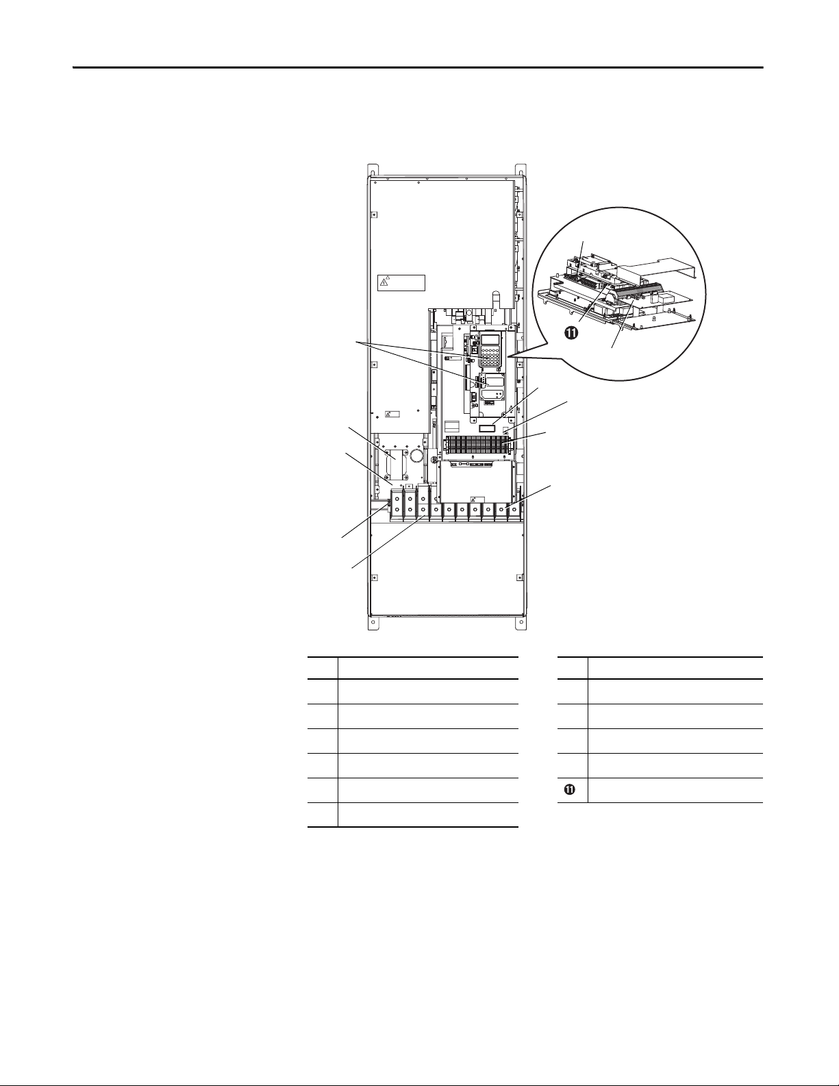
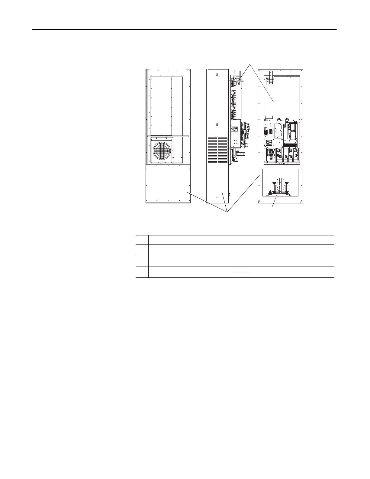
Component Locations
Frame 7
No. Component No. Component
Power Terminal Block
➊
PE Ground
➋
I/O & Auxiliary Control Voltage - TB11
➌
Fan Terminal Block (DC input only)
➍
Fan Transformer (AC input only) Encoder Feedback Board (Optional)
➎
Main Control Board
➏
8 Rockwell Automation Publication 20B-IN014H-EN-P - June 2013
Nameplate
➐
Precharge Board
➑
MOV
➒
HIM/Comm Module (Optional)
➓
Page 9
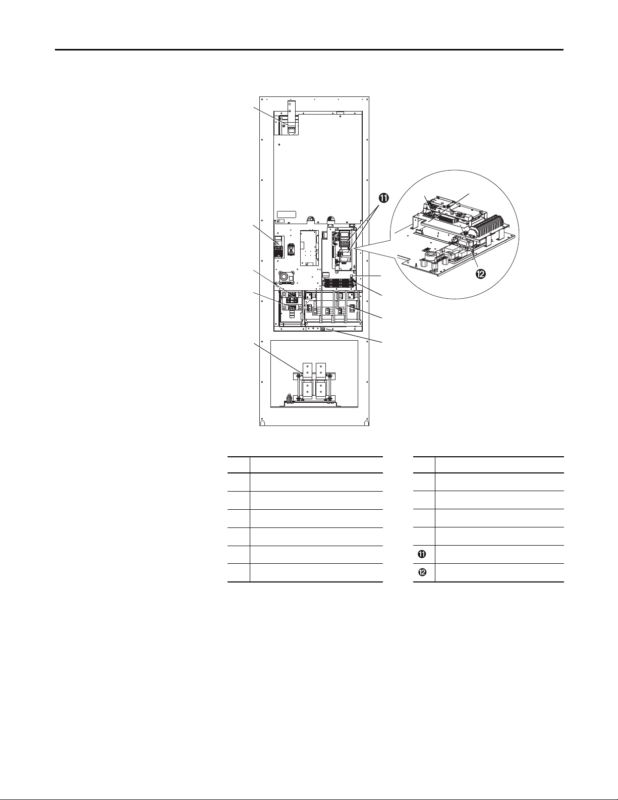
Frame 8
TB11
TE
25 AMPERES RMS
MAXIMUM
RISK OF SHOCK
REPLACE AFTER
SERVICING
!
DANGER
DANGER
RISK OF SHOCK
REPLACE AFTER
SERVICING
!
DANGER
TB9
8 AMPERES RMS
MAXIMUM
DC+
V
W
U
R S T DC-DC+
GND
➊
➋
➌
➍
➓
➎
➐
➑
➏
➒
➋
PowerFlex 700 Adjustable Frequency AC Drive – Frames 7…10
No. Component No. Component
Power Terminals
➊
PE Ground (and MOV wire)
➋
I/O & Auxiliary Control Voltage - TB11
➌
Fan Terminal Block - TB9
➍
Fan Tra nsfor mer (AC input on ly) HIM/Comm Module (Optional)
➎
Main Control Board Encoder Feedback Board (Optional)
➏
Nameplate
➐
DC Bus/Brake Terminals
➑
MOV (under boards)
➒
DC Link Choke (AC input only)
➓
Rockwell Automation Publication 20B-IN014H-EN-P - June 2013 9
Page 10
PowerFlex 700 Adjustable Frequency AC Drive – Frames 7…10
TB11
TE
25 AMPERES RMS
MAXIMUM
DANGER
RISK OF SHOCK
REPLACE AFTER
SERVICING
!
DANGER
TB9
8 AMPERES RMS
MAXIMUM
DC+
V
W
U
R S T DC-DC+
GND
4 T22 T1 6 T3
CAUTION
➊
➋
➌
➍
➓
➎
➑
➐
➏
➒
➋
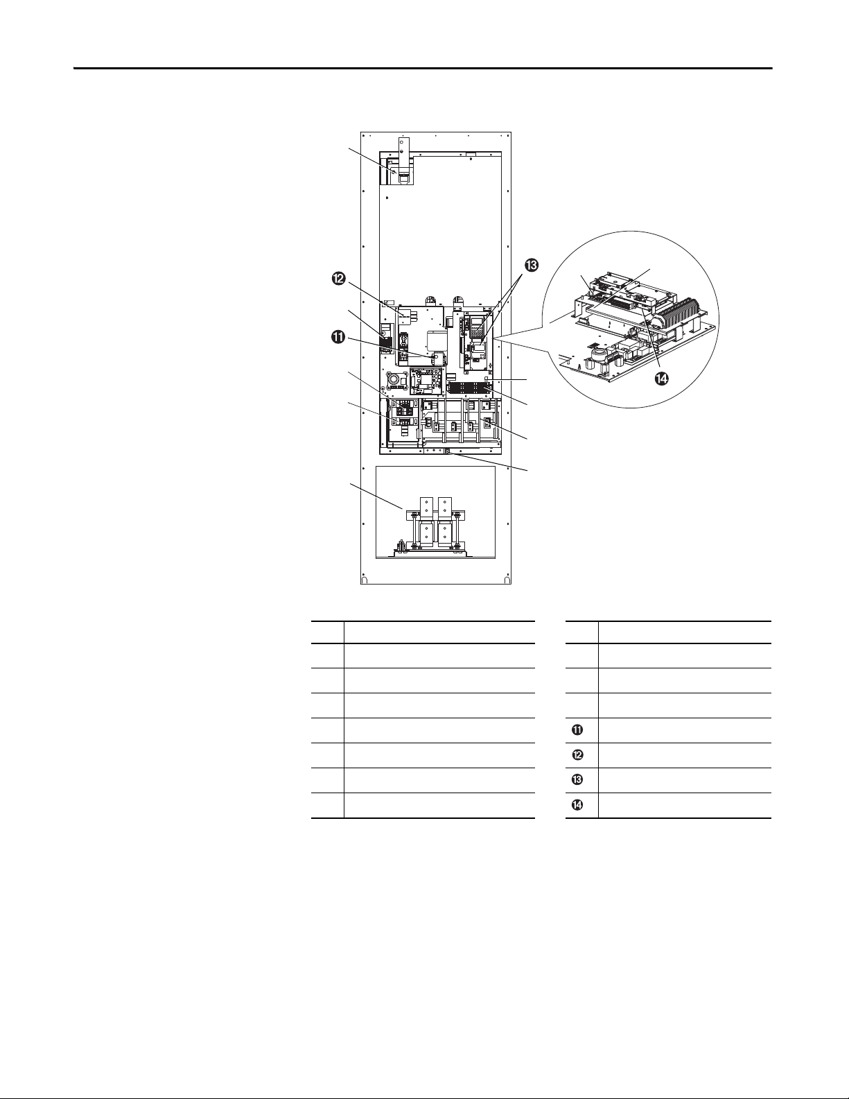
Frames 9
No. Component No. Component
Power Terminals
➊
PE Ground (and MOV wire)
➋
I/O & Auxiliary Control Voltage - TB11
➌
Fan Terminal Block (cap. fan) - TB9 Phase Monitor Relay
➍
Fan Transformer (cap. fan) - AC input only Blower Terminal Block (three-phase)
➎
Main Control Board HIM/Comm Module (Optional)
➏
Nameplate Encoder Feedback Board (Optional)
➐
DC Bus/Brake Terminals
➑
MOV (under boards)
➒
DC Link Choke (AC input only)
➓
10 Rockwell Automation Publication 20B-IN014H-EN-P - June 2013
Page 11
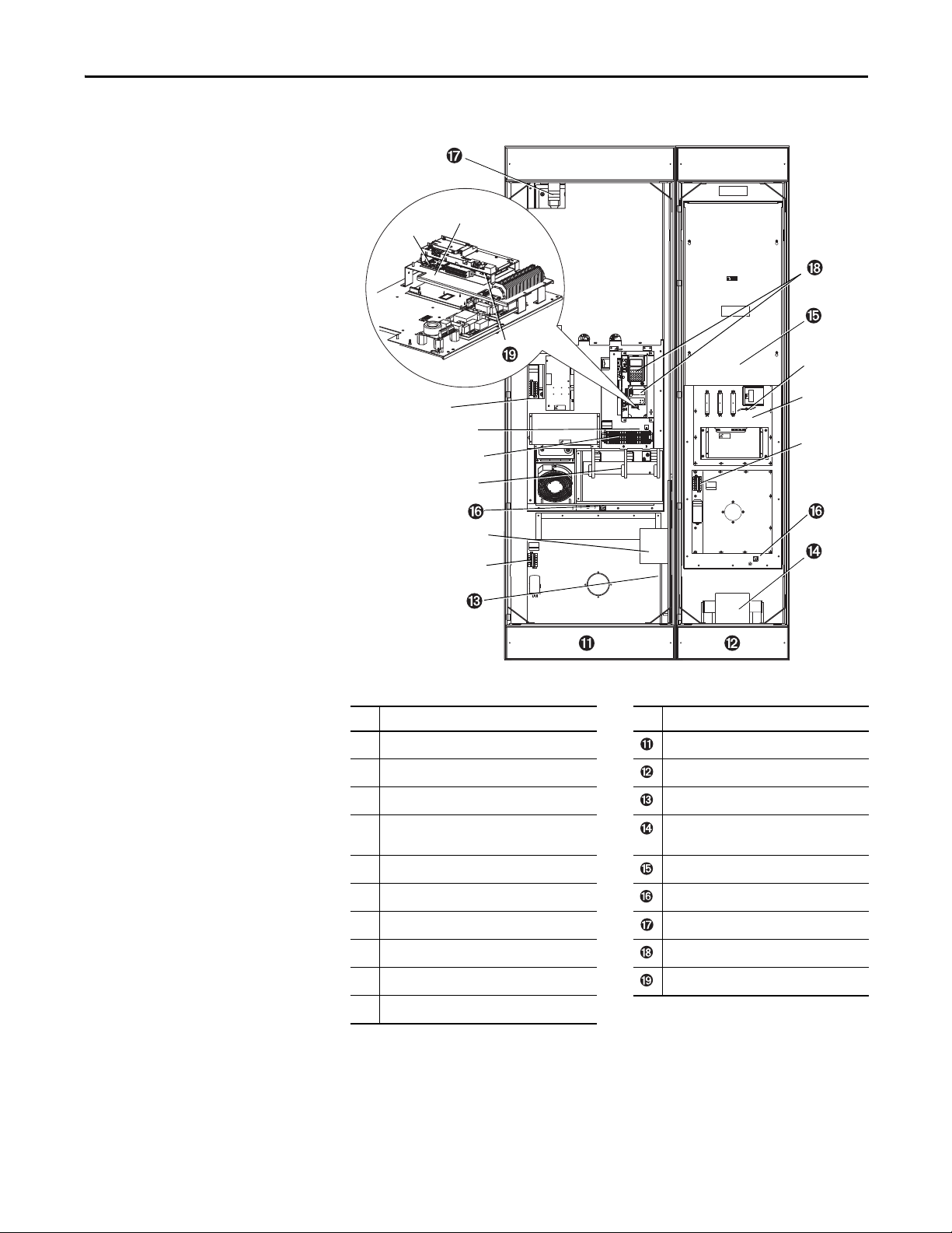
Frame 10
➋
➍
➎
➒
➐
➏
➑
➌
➓
➊
➐
PowerFlex 700 Adjustable Frequency AC Drive – Frames 7…10
DC+
DANGER
!
DANGER
RISK OF SHOCK
REPLACE AFTER
SERVICING
TB9
8 AMPERES RMS
MAXIMUM
120
IN1
120
IN2
3
4
5
6
!
DANGER
RISK OF SHOCK
REPLACE AFTER
SERVICING
TB11
25 AMPERES RMS
MAXIMUM
!
DANGER
RISK OF SHOCK
REPLACE AFTER
SERVICING
PE
VWU
GND
TB10
8 AMPERES RMS
MAXIMUM
120
IN1
120
IN2
3
4
5
6
DANGER
DANGER
!
DANGER
RISK OF SHOCK
REPLACE AFTER
SERVICING
120
IN1
120
IN2
3
TB10
4
8 AMPERES RMS
MAXIMUM
5
6
GND
AC Input drive is shown. For DC Input drives, reference the left Inverter section.
No. Component No. Component
Motor Terminal Block Inverter Section
➊
PE Ground Converter Section
➋
I/O & Auxiliary Control Voltage - TB11 PE Bus Bar (IP20 Only)
➌
Fan Terminal Block - TB9
➍
(Capacitor Assembly Fan)
Fan Transformer (IP20 Only) AC Input Terminals (Behind Shield)
➎
Fan Terminal Block - TB10 (Heatsink Fan) PE Connection Point (IP00)
➏
Nameplate DC Bus/Brake Terminals
➐
Main Control Board HIM/Comm Module (Optional)
➑
MOV Jumper Encoder Feedback Board (Optional)
➒
Fan Terminal Block - TB12 (Heatsink Fan)
➓
DC Link Choke
(AC input only, supplied loose for IP00)
Rockwell Automation Publication 20B-IN014H-EN-P - June 2013 11
Page 12
PowerFlex 700 Adjustable Frequency AC Drive – Frames 7…10
IMPORTANT
Lifting Holes
4 Places
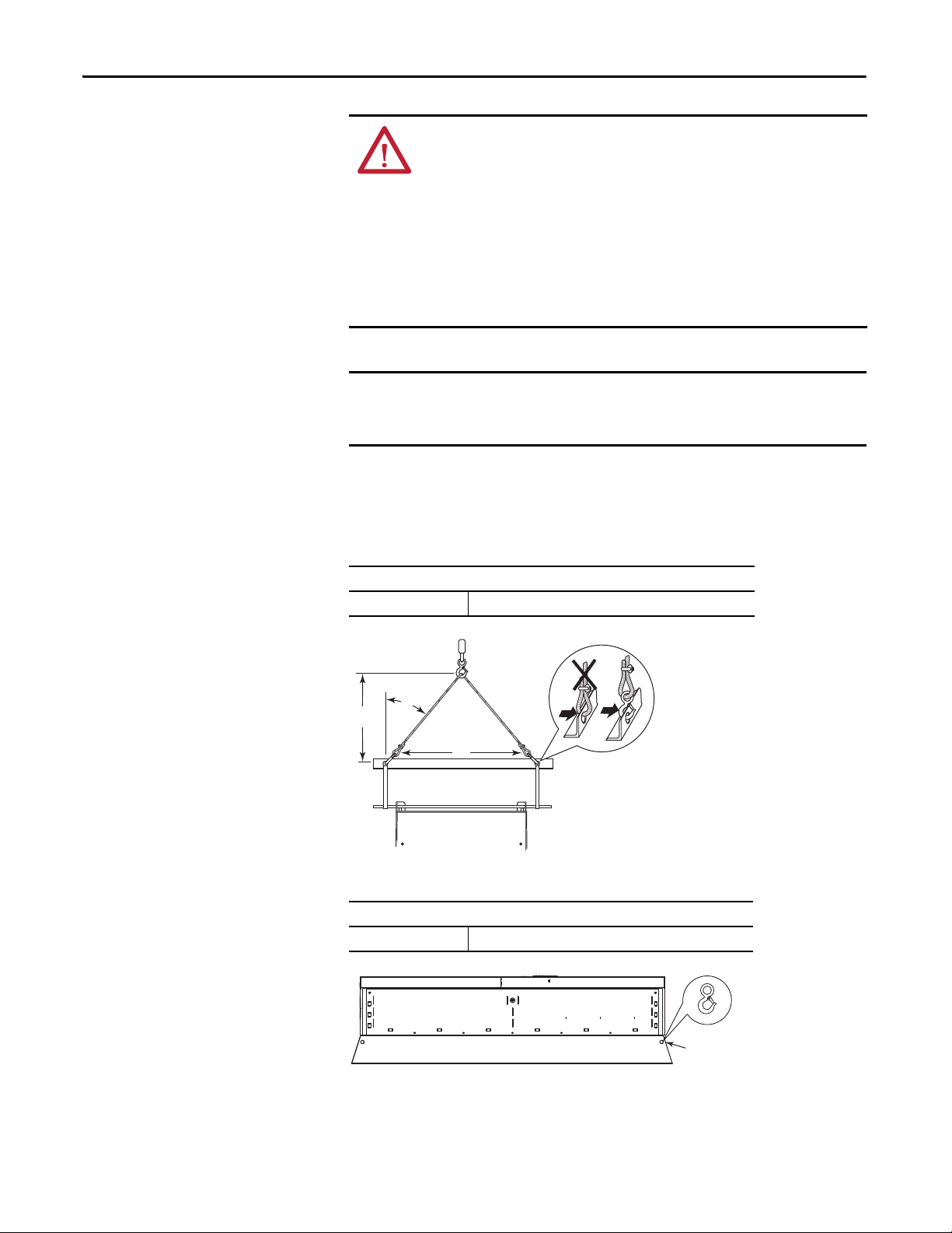
Step 2: Lifting and Mounting the Drive
ATT EN TI ON : To guard against possible personal injury and/or equipment
damage:
• Do Not allow any part of the drive or lifting mechanism to make contact with
electrically charged conductors or components.
• At no time should a person or their limbs be directly underneath the items
being lifted.
• Do not subject the load to high rates of acceleration or deceleration.
• Inspect all lifting hardware for proper attachment before lifting drive unit.
Braces attached to the front of Frame 8, 9 or 10 IP20, NEMA/UL Type 1 drives
are required for structural integrity. If necessary, the braces can be removed for
wiring, but must be replaced upon completion.
Lifting
Frame 7
IP00, NEMA/UL Type Open
Approximate Weight 147 kg (324 lbs.) + 26 kg (58 lbs.) for shipping materials
45°
1
/
>
2 A
A
IP20, NEMA/UL Type 1
Approximate Weight 170 kg (375 lbs.) + 26 kg (58 lbs.) for shipping materials
12 Rockwell Automation Publication 20B-IN014H-EN-P - June 2013
Page 13
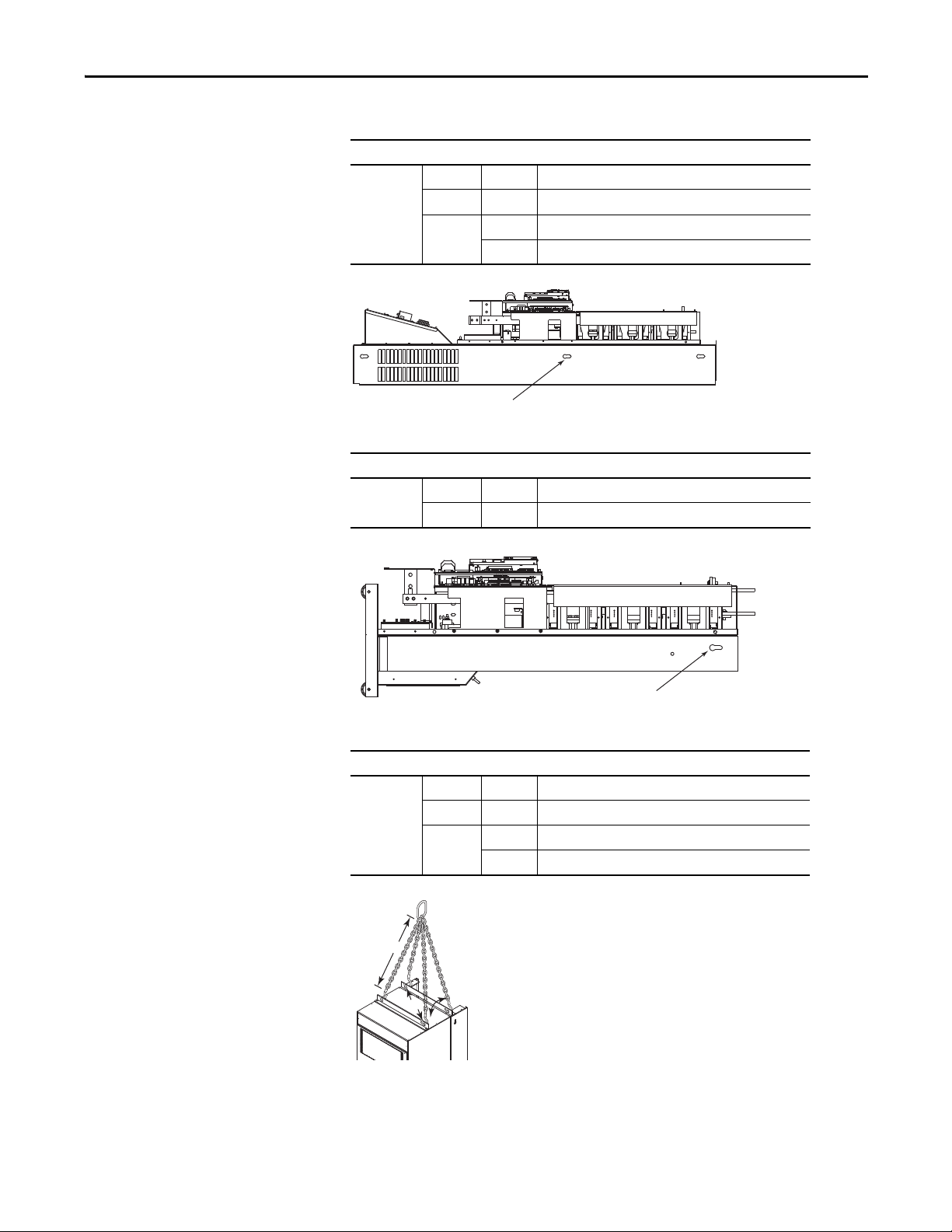
Frames 8, 9 and 10
Lifting Holes 2 Places
>A
A
>60°
Important: a lifting angle must be used. Do Not
use the lifting holes on the side of the cabinet
IP00, NEMA/UL Type Open
Approximate
Wei ght
IP00, NEMA/UL Type Open Roll-In
Approximate
Wei ght
Frame 8 – 384 kg (847 lbs.) + 47 kg (103 lbs.) for shipping materials
Frame 9 – 401 kg (884 lbs.) + 47 kg (103 lbs.) for shipping materials
Frame 10 DC Input 305 kg (672 lbs.) + 47 kg (103 lbs.) for shipping materials
AC input 532 kg (1172 lbs.) + 91 kg (200 lbs.) for shipping materials
Lifting Holes 6 Places
Frame 8 – 250 kg (552 lbs.) + 47 kg (103 lbs.) for shipping materials
Frame 9 – 267 kg (589 lbs.) + 47 kg (103 lbs.) for shipping materials
PowerFlex 700 Adjustable Frequency AC Drive – Frames 7…10
IP20, NEMA/UL Type 1
Approximate
Wei ght
Frame 8 – 509 kg (1122 lbs.) + 47 kg (103 lbs.) for shipping materials
Frame 9 – 526 kg (1159 lbs.) + 47 kg (103 lbs.) for shipping materials
Frame 10 DC Input 468 kg (1032 lbs.) + 47 kg (103 lbs.) for shipping materials
AC input 867 kg (1912 lbs.) + 91 kg (200 lbs.) for shipping materials
Rockwell Automation Publication 20B-IN014H-EN-P - June 2013 13
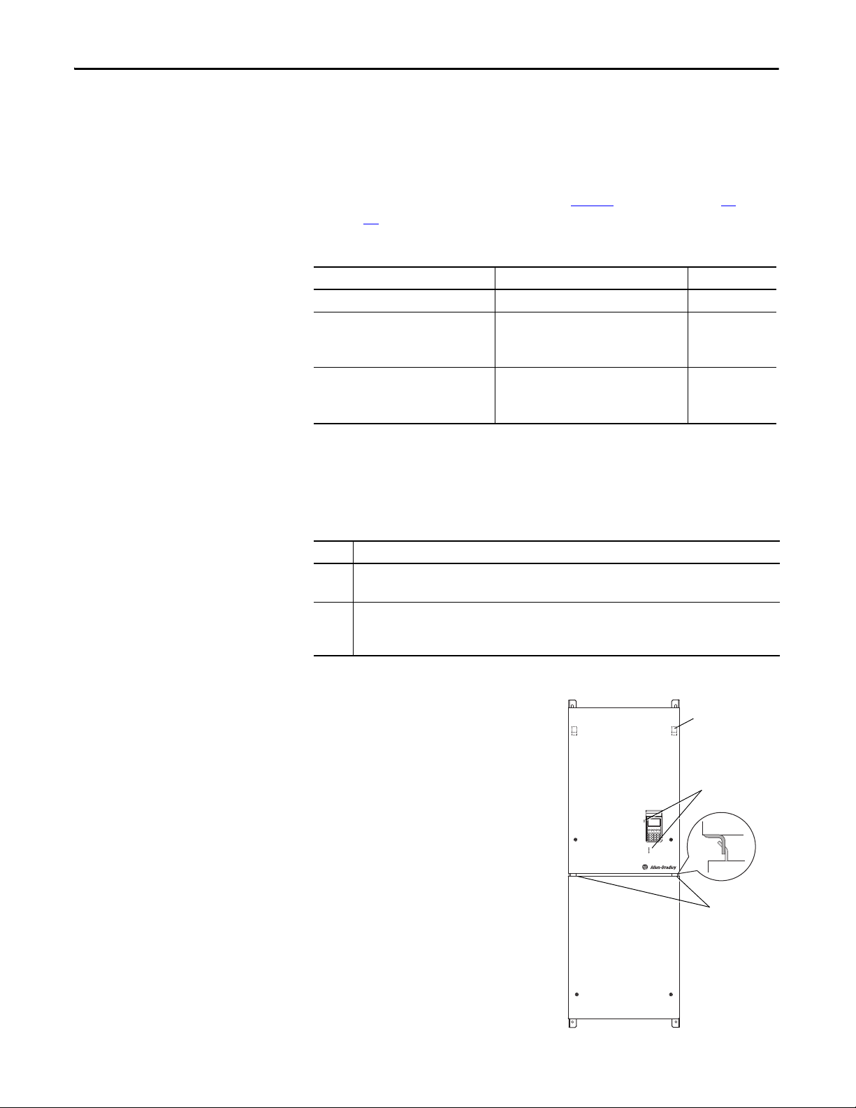
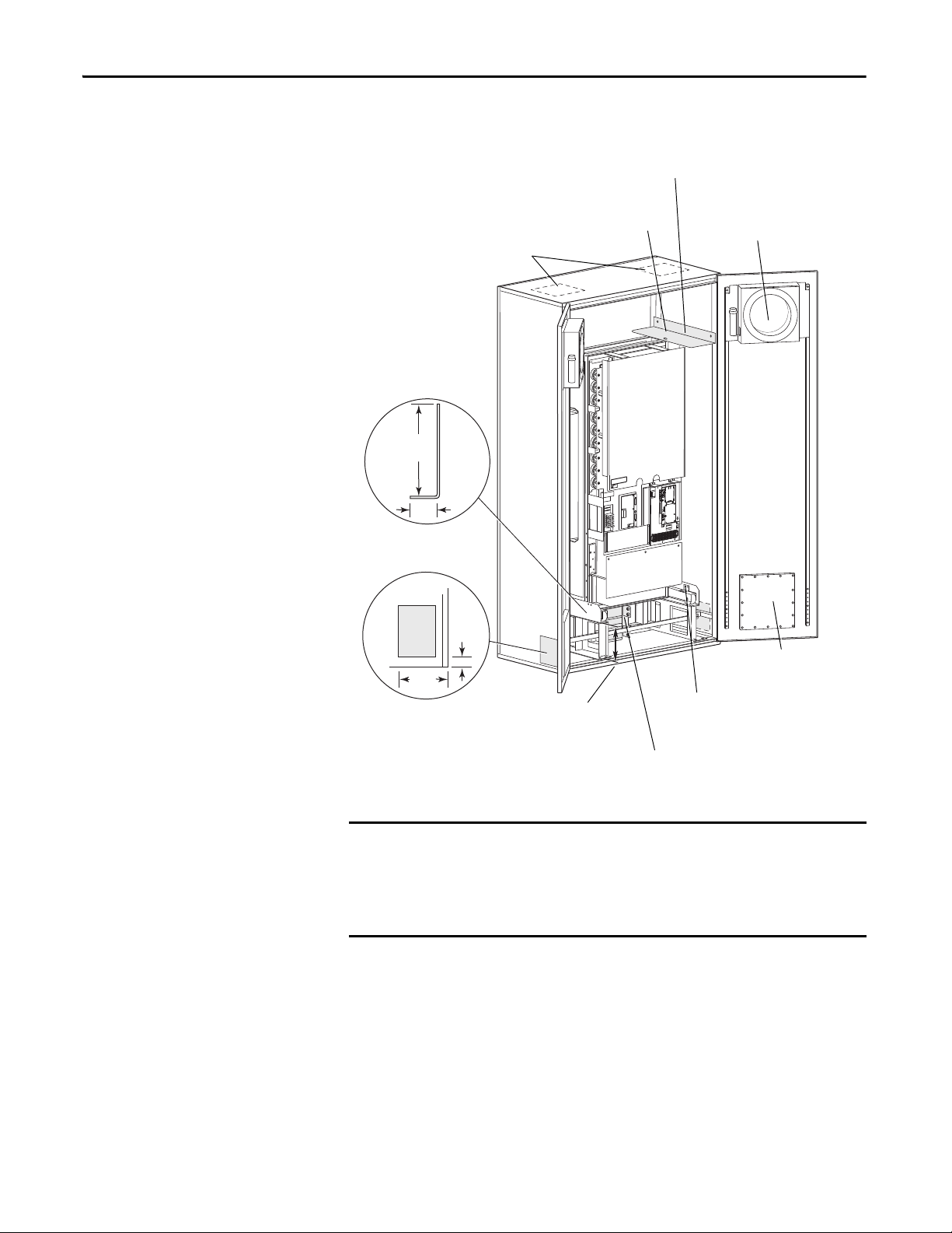
Page 14
PowerFlex 700 Adjustable Frequency AC Drive – Frames 7…10
Locating Tabs
(backside of panel)
Hinge Tabs
Light Pipes
Environment
Operating Temperatures
PowerFlex 700 drives are designed to operate at 0…40 °C ambient. To operate the
drive in installations between 41…50 °C, see Ta b l e 2
through 44
Table 2 - Acceptable Surrounding Air Temperature & Required Actions
Enclosure Rating Temperature Range Drive
IP20, NEMA/UL Type 1 0…40 °C (0…104 °F) Frames 7…10
IP00, NEMA/UL Type Open/Flange Mount
Front: IP00, NEMA/UL Type Open
Back/Heat Sink: IP54, NEMA12
Roll In
Front: IP00, NEMA/UL Type Open
Back/Heat Sink: IP54, NEMA12
for exceptions.
0…65 °C (0…149 °F) Control Board
0…40 °C (0…104 °F) Heat Sink Entry Air
0…65 °C (0…149 °F) Control Board
0…40 °C (0…104 °F) Heat Sink Entry Air
and refer to pages 42
Frames 7…10
Frames 8…9
Minimum Mounting Clearances & Heat Dissipation
The drive must be mounted with sufficient space at the top, sides, and front of the
cabinet to allow for proper heat dissipation.
Frame Recommendations
7 Minimum of 152 mm (6.0 in.) at the top and bottom of the enclosure and 102 mm (4.0 in.) on the sides.
Flange Mount - Minimum of 152 mm (6.0 in.) at the back of the enclosure (flange mount sur face to wall).
8…10 Minimum of 152 mm (6.0 in.) at the top of the enclosure. Additionally, allow a minimum of 102 mm (4.0 in.)
on each side OR 152 mm (6.0 in.) in the back.
Flange Mount - Minimum of 102 mm (4.0 in.) on each side.
Removing the Frame 7 Cover
1. Loosen lower panel screws and pull
the bottom edge out.
2. Tilt panel sufficiently to remove
Hinge Tabs from the upper panel.
Remove panel and set aside.
3. Loosen upper panel screws and pull
bottom edge out slightly.
POWER
STS
PORT
MOD
NET A
NET B
4. Slide panel down until Locating
Tabs clear chassis. Remove panel
and set aside.
5. Replace panels in reverse order.
Carefully align tabs and light pipes.
14 Rockwell Automation Publication 20B-IN014H-EN-P - June 2013
Page 15
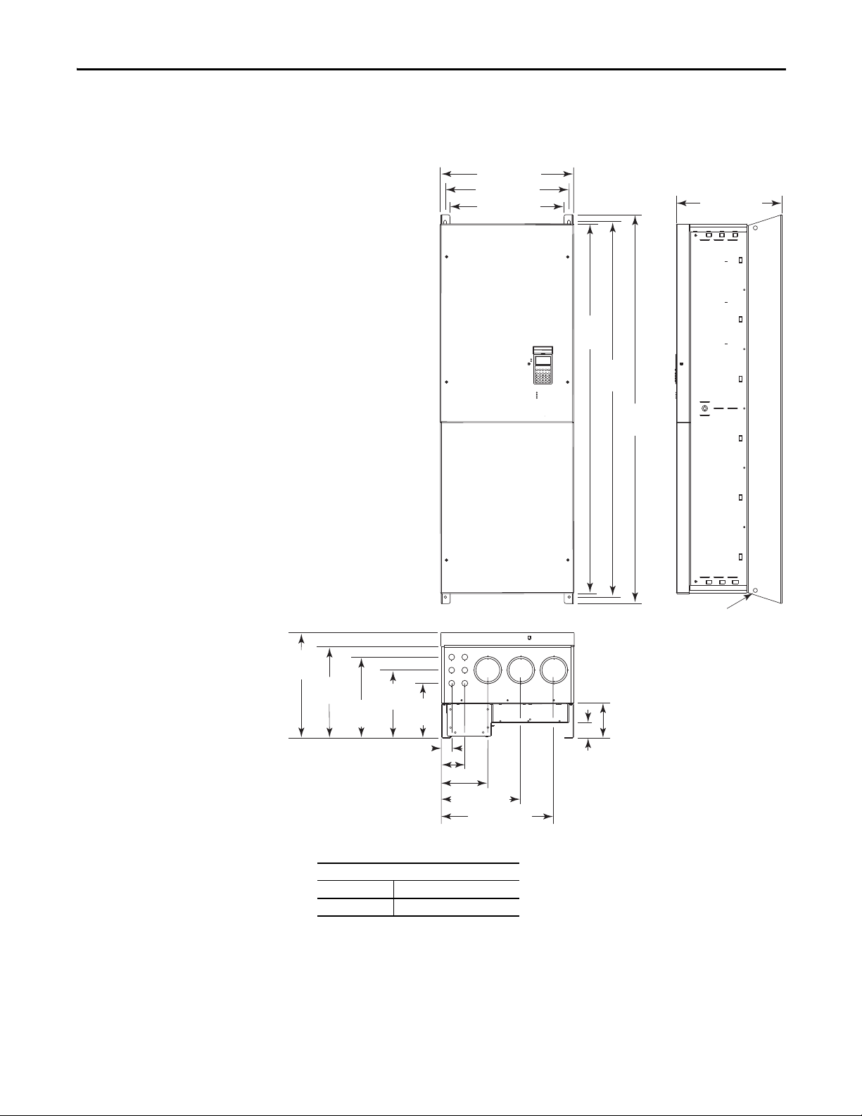
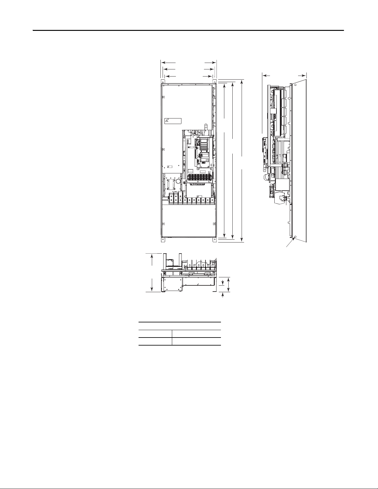
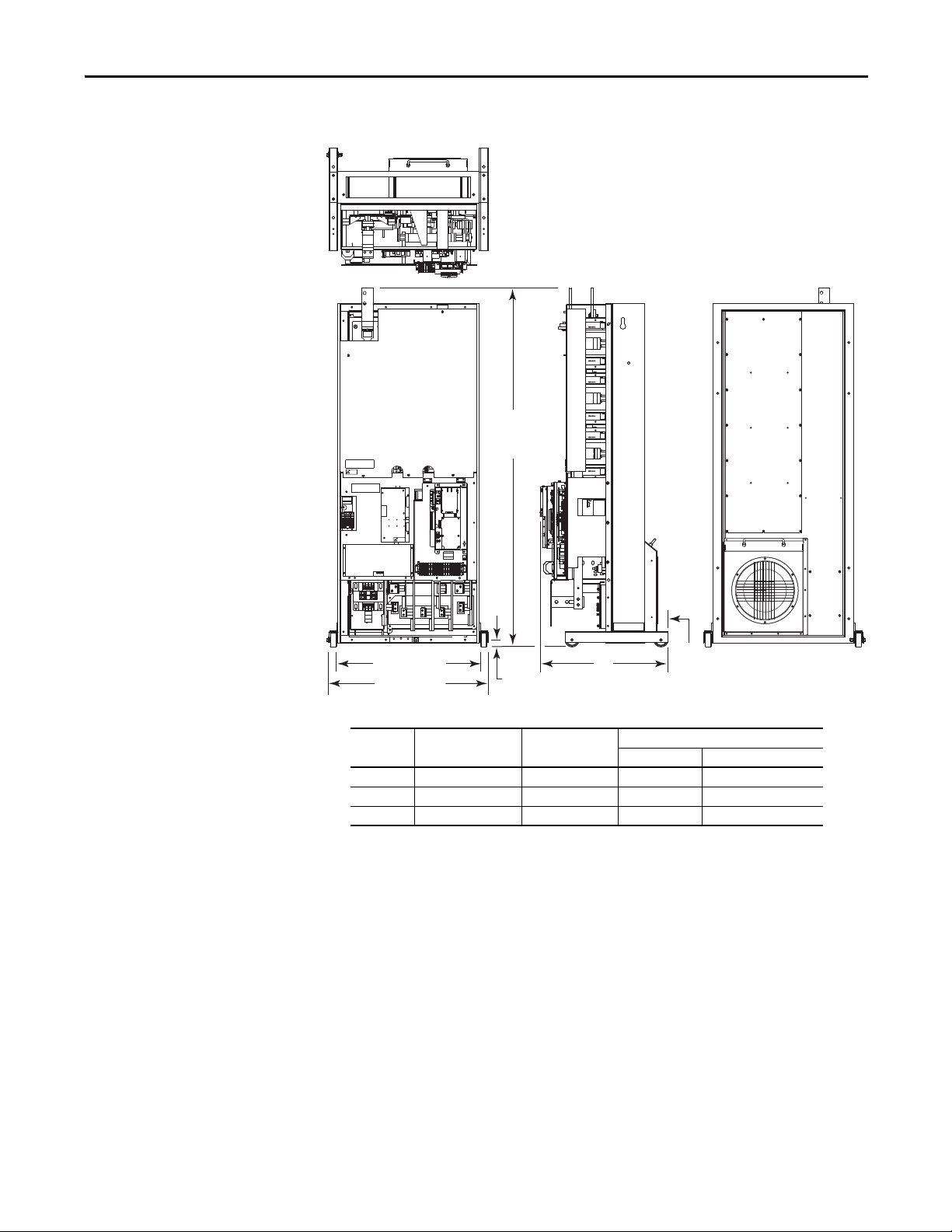
Dimensions
Dimensions are in millimeters and (inches)
Frame 7 – IP20, NEMA/UL Type 1
514.4 (20.25)
477.3 (18.79)
440.2 (17.33)
PowerFlex 700 Adjustable Frequency AC Drive – Frames 7…10
406.5 (16.00)
1424.7
(56.01)
1447.8
PORT
MOD
NET A
NET B
(57.00)
1498.6
(59.00)
406.7
(16.01)
354.3
(13.95)
312.4
261.6
(10.30)
(12.30)
38.7 (1.52)
Approx. Weight kg (lbs.)
Drive Drive & Packaging
170 (375) 1 96 (433)
210.8
(8.30)
89.5 (3.52)
178.4 (7.02)
Lifting Holes
4 Places
134.6
(5.30)
58.5
(2.30)
305.4 (12.02)
432.4 (17.02)
Rockwell Automation Publication 20B-IN014H-EN-P - June 2013 15
Page 16
PowerFlex 700 Adjustable Frequency AC Drive – Frames 7…10
Dimensions are in
millimeters and (inches)
Frame 7 – IP00, NEMA/UL Type Open
509.3 (20.05)
477.3 (18.79)
440.2 (17.33)
!
DANGER
409.3 (16.11)
1419.1
(55.87)
354.3
(13.95)
!
DANGER
RISK OF SHOCK
REPLACE AFTER
SERVICING
+DC
-DC PE PE R-L1 T-L3
USE 75° COPPER WIRE ONLY
CAUTION
!
HOT SURFACES
TB11
25 AMPERES RMS
MAXIMUM
ALLEN-BRADLEY
MADE IN U.S.A.
TORQUE LARGE TERMINALS TO 10 N-m (87LB-IN)
1447.8
(57.00)
1498.6
PE
!
DANGER
RISK OF SHOCK
REPLACE AFTER
SERVICING
U-M1 V-M2 W-M3S-L2
(59.00)
Lifting Holes
4 Places
133.4
(5.25)
58.9
(2.32)
Approx. Weight kg (lbs.)
Drive Drive & Packaging
147 (324) 173 (382)
16 Rockwell Automation Publication 20B-IN014H-EN-P - June 2013
Page 17
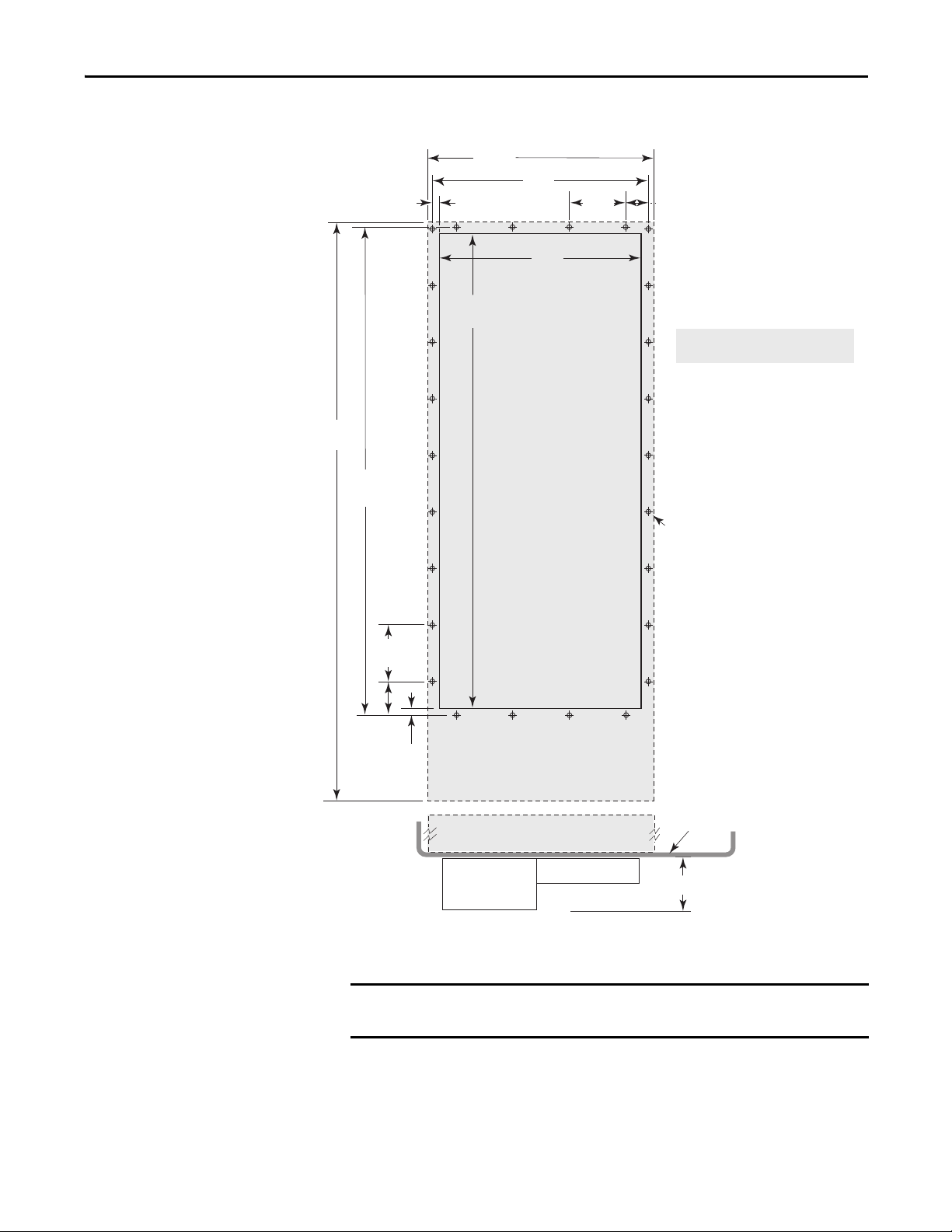
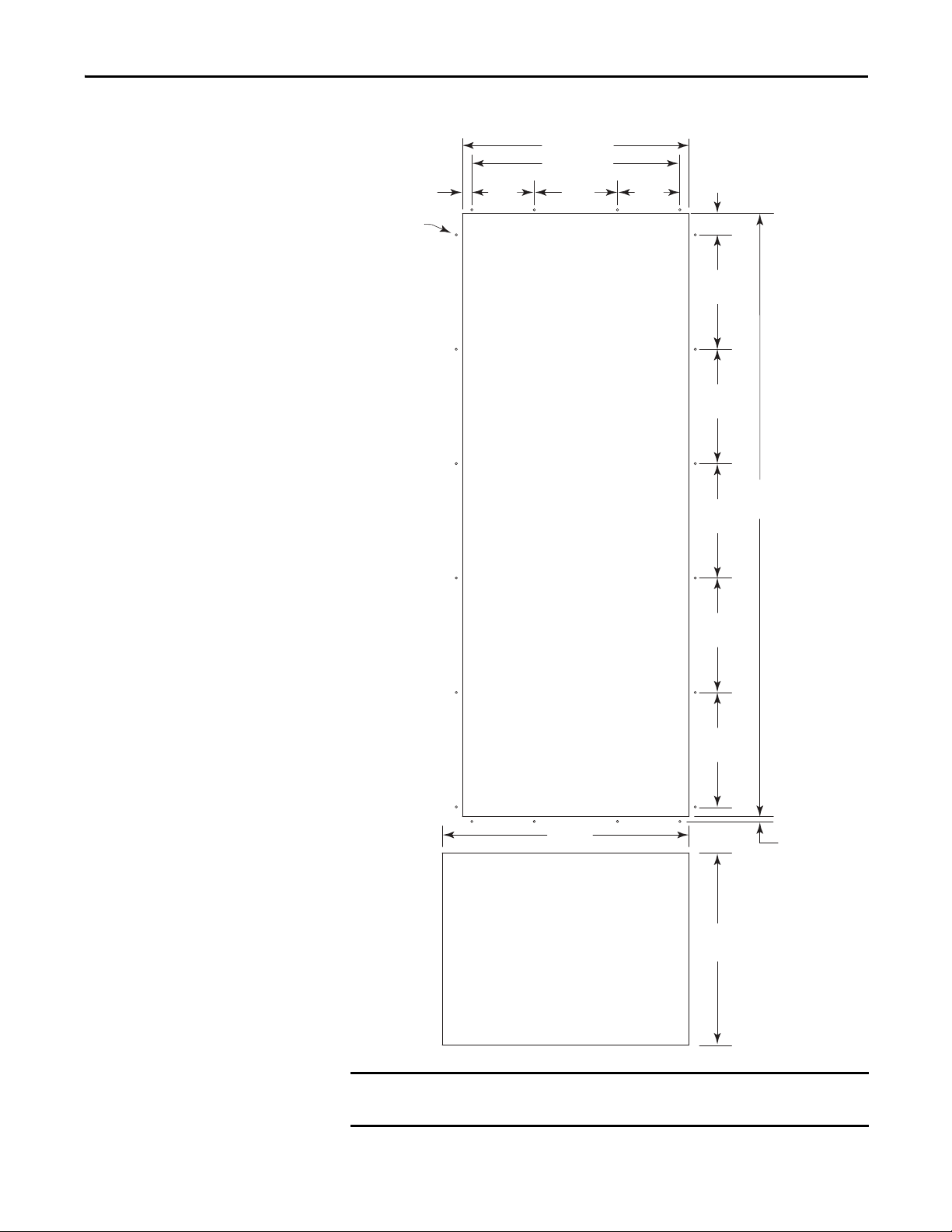
Frame 7 – Flange Mount Cutout
Dimensions are in millimeters and (inches)
IMPORTANT
5.8
(0.23)
1422.4
(56.00)
1095.8
(43.14)
1084.1
(42.68)
508.0
(20.00)
Cutout
489.0
(19.25)
477.3
(18.79)
PowerFlex 700 Adjustable Frequency AC Drive – Frames 7…10
127.0
(5.00)
54.1
(2.13)
Shading indicates approximate size
of drive inside enclosure.
127.0
(5.00)
75.4
(2.97)
5.8
(0.23)
Drive
26 Required
4.3 (0.171) Dia. for 10-32 x 9.7 (0.38) Self-Tap
4.0 (0.159) for 10-32 x 9.7 (0.38) Threaded
* Minimum dimension allowed – More space
will improve fan eectiveness and heat
dissipation.
Back of Enclosure
132.3 (5.21) *
Use gasket kit catalog number SK-G1-GASKET1-F7 with user supplied IP54,
NEMA/UL Type 12 enclosure.
Rockwell Automation Publication 20B-IN014H-EN-P - June 2013 17
Page 18
PowerFlex 700 Adjustable Frequency AC Drive – Frames 7…10
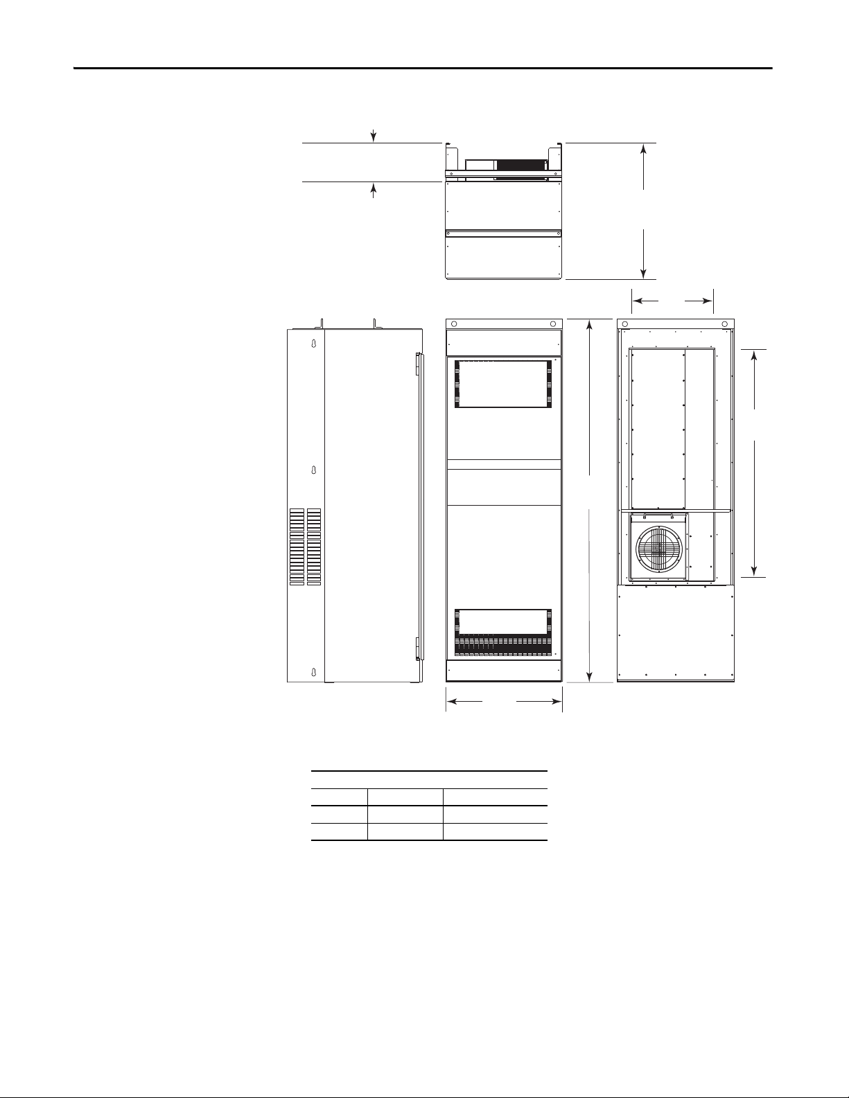
Dimensions are in millimeters and (inches)
Frames 8 and 9 – IP20, NEMA/UL Type 1
254.6 (10.02) - 20Bx365, 415, 481
381.7 (15.03) - 20Bx535, 600, 730
898.8 (35.39) - 20Bx365, 415, 481
1025.9 (40.39) - 20Bx535, 600, 730
549.7
(21.64)
1466.6
(57.74)
757.9
(29.84)
Approx. Weight kg (lbs.)
Frame Drive Drive & Packaging
8 509 (1122) 55 6 (1225)
9 526 (1159) 60 3 (1262)
2349.1
(92.49)
18 Rockwell Automation Publication 20B-IN014H-EN-P - June 2013
Page 19
TB11
TE
25 AMPERES RMS
MAXIMUM
RISK OF SHOCK
REPLACE AFTER
SERVICING
!
DANGER
DANGER
RISK OF SHOCK
REPLACE AFTER
SERVICING
!
DANGER
TB9
8 AMPERES RMS
MAXIMUM
DC+
VWU
R S T DC-DC+
GND
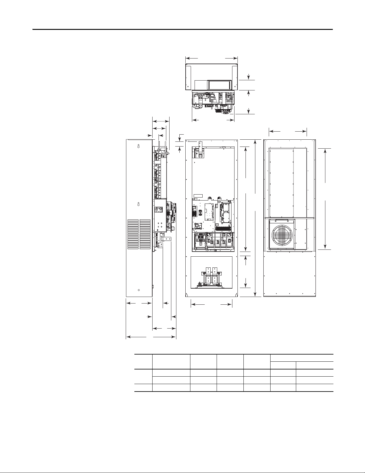
2283.7
(89.91)
463.8
(18.26)
603.0
(23.74)
1524.0
(60.00)
71.3 (2.81)
A
C
B
153.0
(6.02)
274.3
(10.80)
193.3 (7.61)
241.0 (9.49)
549.7
(21.64)
1466.6
(57.74)
85.5 (3.37)
757.8 (29.83)
145.3
(5.72)
See
Table
612.8 (24.13)
Dimensions are in millimeters and (inches)
PowerFlex 700 Adjustable Frequency AC Drive – Frames 7…10
Frames 8 and 9 – IP00, NEMA/UL Type Open
Frame Cat. No. A B C
8 20Bx365, 415, 481 254.6 (10.02) 345.3 (13.59) 599.4 (2 3.60) 384 (847) 431 (950)
20Bx535, 600 381.7 (15.03) 345.5 (13. 60) 726.6 (28.61) 384 (847) 431 (950)
Approx. Weight kg (lbs.)
Drive Drive & Packaging
9 20Bx730 381.1 (15.00) 345.3 (13.60) 771.9 (30.39) 401 (884) 448 (987)
Rockwell Automation Publication 20B-IN014H-EN-P - June 2013 19
Page 20
PowerFlex 700 Adjustable Frequency AC Drive – Frames 7…10
TB11
TE
25 AMPERES RMS
MAXIMUM
RISK OF SHOCK
REPLACE AFTER
SERVICING
!
DANGER
DANGER
RISK OF SHOCK
REPLACE AFTER
SERVICING
!
DANGER
TB9
8 AMPERES RMS
MAXIMUM
DC+
VWU
R S T DC-DC+
GND
➊
➋
➌
Frames 8 and 9 – Converting an IP00 Drive for Flange Mounting
No. Component
Remove these IP00 enclosure components.
➊
Drive assembly to be flange mounted.
➋
DC link choke - mounts separately in enclosure (see page 28 for dimensions) and is wired direc tly to drive.
➌
20 Rockwell Automation Publication 20B-IN014H-EN-P - June 2013
Page 21
PowerFlex 700 Adjustable Frequency AC Drive – Frames 7…10
TB11
TE
25 AMPERES RMS
MAXIMUM
RISK OF SHOCK
REPLACE AFTER
SERVICING
!
DANGER
DANGER
DANGER
RISK OF SHOCK
REPLACE AFTER
SERVICING
!
DANGER
TB9
8 AMPERES RMS
MAXIMUM
DC+
V
W
U
RSTDC-DC+
648.2 (25.52)
1612.4
(63.48)
719.8 (28.34)
A
45.2
(1.78)
31.8
(1.24)
Dimensions are in millimeters and (inches)
Frames 8 and 9 Roll-In – IP00, NEMA/UL Type Open
Frame C at. No. A
Approx. Weight kg (lbs.)
Drive Drive & Packaging
8 20Bx365, 415, 481 574.8 (22.63) 25 0 (552) 297 (655)
8 20Bx535, 600 574.8 (22.63) 25 0 (552) 297 (655)
9 20Bx730 594.3 (23.40) 267 (589) 314 (692)
Rockwell Automation Publication 20B-IN014H-EN-P - June 2013 21
Page 22
PowerFlex 700 Adjustable Frequency AC Drive – Frames 7…10
IMPORTANT
Typical Fan Location
(2 Places - 1 Each Door)
Typ ica l Bra cke t
(May require additional anchoring for shipping)
Suggested Anchoring Point
(M10 Ha rdware Required)
Alternate Fan Locations
Typical Rail Detail
Cable Access Plate
(2 Places)
DC Link Choke
Mounted Separately - Typical Placement Shown
203.2…355.6 mm
(8.00…14.00 in.) Typical
Suggested Anti-Roll
Anchoring Point
Typical Air Inlet
(2 Places - 1 Each Door)
Frames 8 and 9 Roll-In Mounting Considerations
107.4
D =
(4.23)
465.8 (18.34)
58.9
(2.32)
GER
N
DA
R
E
G
N
A
K
!
C
D
O
H
S
F
O
K
IS
R
R
E
T
F
A
E
AC
L
P
E
R
G
IN
IC
V
R
SE
9
B
T
S
M
R
S
E
R
E
P
M
A
8
M
U
M
I
X
A
M
R
E
G
N
A
K
!
D
OC
H
S
F
O
K
IS
R
R
TE
F
A
E
C
A
L
P
E
R
G
IN
C
I
V
R
E
S
E
T
1
1
B
T
S
M
R
S
E
R
E
P
M
A
5
2
M
U
M
I
X
A
M
108.0 x 158.8
(4.25 x 6.25)
196.9
(7.75)
19.1
(0.75)
This information illustrates how an open roll-in style drive could be mounted in
a user supplied enclosure. Illustrations are intended only to identify structural
mounting points and hardware shapes. You must design and fabricate steel
components based on the actual mounting configuration, calculated loads and
enclosure specifications. Minimum thickness of all parts = 4.6 mm (0.18 in.).
22 Rockwell Automation Publication 20B-IN014H-EN-P - June 2013
Page 23
IMPORTANT
1471.9
(57.95)
279.4
(11.00)
279.4
(11.00)
279.4
(11.00)
152.4
(6.00)
152.4
(6.00)
203.2
(8.00)
5.6 (0.22)
20 Places
52.1 (2.05)
22.9 (0.90)
553.3 (21.79)
279.4
(11.00)
279.4
(11.00)
603.0
(23.74)
12.7 (0.50)
508.0 (20.00)
463.8
(18.26)
This cutout is only needed
if recessing the choke
Dimensions are in millimeters and (inches)
PowerFlex 700 Adjustable Frequency AC Drive – Frames 7…10
Frames 8 & 9 Flange Mount Cutout
Use gasket kit catalog number SK-G1-GASKET1-F89 with user supplied IP54,
Rockwell Automation Publication 20B-IN014H-EN-P - June 2013 23
NEMA/UL Type 12 enclosure.
Page 24

PowerFlex 700 Adjustable Frequency AC Drive – Frames 7…10
890.8
(35.07)
2374.0
(93.46)
1268.7
(49.95)
761.3
(29.97)
507.4
(19.98)
Dimensions are in millimeters and (inches)
Frame 10 – IP20, NEMA/UL Type 1
AC Input Shown, for DC Input Dimensions use the Inverter (Left) Bay
Approx. Weight kg (lbs.)
Type Drive Drive & Packaging
DC Input 468 (1032) 515 (1135)
AC Input 867 (1912) 958 (2112)
24 Rockwell Automation Publication 20B-IN014H-EN-P - June 2013
Page 25

PowerFlex 700 Adjustable Frequency AC Drive – Frames 7…10
120
IN1
120
IN2
3
4
5
6
DC+
DANGER
DANGER
DANGER
TB9
8 AMPERES RMS
MAXIMUM
120
IN1
120
IN2
3
4
5
6
VWU
TB11
PE
25 AMPERES RMS
MAXIMUM
GND
RISK OF SHOCK
REPLACE AFTER
SERVICING
!
DANGER
RISK OF SHOCK
REPLACE AFTER
SERVICING
!
DANGER
RISK OF SHOCK
REPLACE AFTER
SERVICING
!
DANGER
TB10
8 AMPERES RMS
MAXIMUM
120
IN1
120
IN2
3
4
5
6
TB10
8 AMPERES RMS
MAXIMUM
GND
RISK OF SHOCK
REPLACE AFTER
SERVICING
!
DANGER
543.6
(21.40)
591.8
(23.30)
2275.8
(89.60)
252.7
(9.95)
473.4
(18.64)
1267.8
(49.91)
757.8
(29.83)
503.7
(19.83)
353.8
(13.93)
445.8
(17.55)
Dimensions are in millimeters and (inches)
Frame 10 – IP00, NEMA/UL Type Open
AC Input Shown, for DC Input Dimensions use the Inverter (Left) Bay
Approx. Weight kg (lbs.)
Type Drive Drive & Packaging
DC Input 305 (672) 352 (775)
AC Input 532 (1172) 623 (1372)
Rockwell Automation Publication 20B-IN014H-EN-P - June 2013 25
Page 26

PowerFlex 700 Adjustable Frequency AC Drive – Frames 7…10
IMPORTANT
Dimensions are in millimeters and (inches)
Frame 10 – Flange Mount Cutout
22.9
(0.90)
52.1 (2.05)
279.4 (11.00)
hole spacing,
5 places,
both sides
66.5 (2.62)
508.0 (20.00)
355.6 (14.00)
152.4
(6.00)
553.3 (21.79)
1471.9
(57.95)
Inverter Converter
22.5
(0.89)
37.7
(1.49)
22.9 (0.90)
12.7 (0.50)
58.6 (2.31)
38.1
(1.50)
152.4
(6.00)
381.0 (15.00)
152.4
(6.00)
32.3 (1.27)
39.9 (1.57)
7.6 (0.30)
1588.5
(62.54)
254.0 (10.00)
hole spacing
5 places,
both sides
See Detail
Holes are for M6 self tapping screws.
Backplate and extension are a single piece. Drive chassis can be removed from
backplate to mount in user supplied IP54, NEMA/UL Type 12 enclosure.
26 Rockwell Automation Publication 20B-IN014H-EN-P - June 2013
Page 27

Frame 10 – Flange Mount Cutout Detail
IMPORTANT
Dimensions are in millimeters and (inches)
95.9 (3.77)
178.8(7.04)
558.2 (21.98)
543.3 (21.39)
24.9 (0.98)
28.7 (1.13)
*
PowerFlex 700 Adjustable Frequency AC Drive – Frames 7…10
328.8 (12.94)
478.8 (18.85)
*
530.8 (20.90)
486.5 (19.15)
414.7 (16.33)
363.7 (14.32)
271.2 (10.68)
127.7 (5.03)
Ref. (0.00)
15.8 (0.62)
*
*
*
**
14.7 (0.58)
Ref. (0.00)
Fan studs are installed in alternating
directions. “ * ” indicates that the stud
points-in, all others point-out.
Fan Stud “Pointing-Out”
(Outside of Enclosure)
93.7 (3.69)
121.1 (4.77)
Enclosure Wall
Fan Stud “Pointing-In”
(Inside of Enclosure)
253.7 (9.99)
413.8 (16.29)
*
*
*
**
507.5 (19.98)
522.2 (20.56)
Backplate and extension are a single piece. Drive chassis can be removed from
backplate to mount in user supplied IP54, NEMA/UL Type 12 enclosure.
425.6 (16.75)
343.0 (13.50)
199.5 (7.85)
56.0 (2.20)
Rockwell Automation Publication 20B-IN014H-EN-P - June 2013 27
Page 28

PowerFlex 700 Adjustable Frequency AC Drive – Frames 7…10
370.8 (14.60)
396.2 (15.60)
179.8
(7.08)
217.9
(8.58)
228.6
(9.00) Max.
19.1 (0.75)
16.0 x 9.7 (0.63 x 0.38)
4 Places
203.2 (8.00)
279.4 (11.00)
4.7 (0.19)
215.9
(8.50) Max.
4.8
(0.19)
54.1
(2.13)
54.1
(2.13)
10.2 (0.40) Min.
162.1
(6.38)
Dimensions are in millimeters
and (inches)
Dimensions are in millimeters
and (inches)
DC Link Choke – Frame 8
DC Link Choke – Frame 9
14.2 (0.56)
188.0
(7.40)
218.4
(8.60)
28 Rockwell Automation Publication 20B-IN014H-EN-P - June 2013
101.6
(4.00)
287.0
(11.30)
214.4
(8.44)
35.3
(1.39)
342.9 (13.50)
304.8 (12.00)
50.8
(2.00)
L1
L2 L3
50.8
(2.00)
25.4 (1.00)
L4
Page 29

See Detail
Dimensions are in millimeters and (inches)
DC Link Choke – Frame 10
266.7 (10.50) Max
220.9 (8.70)
Top
PowerFlex 700 Adjustable Frequency AC Drive – Frames 7…10
Detail
219.7
(8.65)
31.8 (1.25)
9.5 (0.38) Dia.
280.7
(11.05)
251.0
(9.90)
244.6 (9.63)
57.2 (2.25)
121.8 (4.80)
25.4
(1.00) Dia.
2 Places
Front Side
12.7 (0.50)
34.9 (1.38)
222.0
(8.74)
247.7
(9.75)
12.7 (0.50)
13.5 (0.53)
31.8 (1.25)
11.8 (0.47)
7.9 (0.31)
4 PLACES
305.0
(12.00)
248.0
(9.76)
Step 3: Wire the Drive
280.7 (11.05)
Special Considerations
PowerFlex 700 drives are suitable for use on a circuit capable of delivering up to a
maximum of 200,000 rms symmetrical amperes.
ATT EN TI ON : To guard against personal injury and/or equipment damage
caused by improper fusing or circuit breaker selection, use only the
recommended line fuses/circuit breakers specified on page 41
.
If a system ground fault monitor (RCD) is used, only Type B (adjustable) devices
can be used to avoid nuisance tripping.
Rockwell Automation Publication 20B-IN014H-EN-P - June 2013 29
Page 30

PowerFlex 700 Adjustable Frequency AC Drive – Frames 7…10
Unbalanced, Ungrounded, Resistive or B Phase Grounded Distribution Systems
If phase to ground voltage exceeds 125% of normal line to line voltage or the
supply system is ungrounded, refer to the Wiring and Grounding Guidelines for
Pulse Width Modulated (PWM) AC Drives, publication DRIVES-IN001
ATT EN TI ON : To guard against drive damage, PowerFlex 700 drives contain
protective MOVs and common mode capacitors that are referenced to ground.
These devices must be disconnected if the drive is not
grounded system. See page 46
for details.
installed on a solidly
.
Input Power Conditioning
Certain events on the power system supplying a drive can cause component
damage or shortened product life. These conditions include:
• The power system has power factor correction capacitors switched in and
out of the system, either by the user or by the power company.
• The power source has intermittent voltage spikes in excess of 6000 volts.
These spikes could be caused by other equipment on the line or by events
such as lightning strikes.
• The power source has frequent interruptions.
If any or all of these conditions exist, it is recommended that the user install a
minimum amount of impedance between the drive and the source. This
impedance could come from the supply transformer itself, the cable between the
transformer and drive or an additional transformer or reactor.
EMC Compliance
Frames 7…10: Drives are CE Certified for use with 400V AC and 480V AC
center grounded neutral power supply systems only. Refer to page 7
for details.
Cable Trays and Conduit
If cable trays or large conduits are to be used, refer to the guidelines presented in
the Wiring and Grounding Guidelines for Pulse Width Modulated (PWM) AC
Drives, publication DRIVES-IN001
ATT EN TI ON : To avoid a possible shock hazard caused by induced voltages,
unused wires in the conduit must be grounded at both ends. For the same
reason, if a drive sharing a conduit is being serviced or installed, all drives using
this conduit must be disabled. This helps to minimize the possible shock hazard
from “cross coupled” motor leads.
.
Motor Cable Lengths
Typically, motor lead lengths less than 91 meters (300 feet) are acceptable.
However, if your application dictates longer lengths, refer to the Wiring and
Grounding Guidelines for Pulse Width Modulated (PWM) AC Drives,
publication DRIVES-IN001
20B-TD001
30 Rockwell Automation Publication 20B-IN014H-EN-P - June 2013
.
or the PowerFlex 700 Technical Data, publication
Page 31

PowerFlex 700 Adjustable Frequency AC Drive – Frames 7…10
Cable Types Acceptable for 200…600 Volt Installations
A variety of cable types are acceptable for drive installations. For many
installations, unshielded cable is adequate, provided it can be separated from
sensitive circuits. As an approximate guide, allow a spacing of 0.3 meters (1 foot)
for every 10 meters (32.8 feet) of length. In all cases, long parallel runs must be
avoided. Do not use cable with an insulation thickness less than or equal to 15
mils (0.4mm/0.015 in.). Use Copper wire only. Wire gauge requirements and
recommendations are based on 75 °C. Do not reduce wire gauge by using higher
temperature wire.
Unshielded
THHN, THWN or similar wire is acceptable for drive installation in dry
environments provided adequate free air space and/or conduit fill rates limits are
provided. Do not use THHN or similarly coated wire in wet areas. Any wire
chosen must have a minimum insulation thickness of 15 Mils and not have large
variations in insulation concentricity.
Shielded/Armored Cable
Shielded cable contains all of the general benefits of multi-conductor cable with
the added benefit of a copper braided shield that can contain much of the noise
generated by a typical AC Drive. Strong consideration for shielded cable must be
given in installations with sensitive equipment such as weigh scales, capacitive
proximity switches and other devices that can be affected by electrical noise in the
distribution system. Applications with large numbers of drives in a similar
location, imposed EMC regulations or a high degree of communications/
networking are also good candidates for shielded cable.
Shielded cable can also help reduce shaft voltage and induced bearing currents for
some applications. In addition, the increased impedance of shielded cable can
help extend the distance between the motor and drive without the addition of
motor protective devices such as terminator networks. Refer to Reflected Wave
in the Wiring and Grounding Guidelines for Pulse Width Modulated (PWM)
AC Drives, publication DRIVES-IN001
Consideration must be given to all of the general specifications dictated by the
environment of the installation, including temperature, flexibility, moisture
characteristics and chemical resistance. In addition, a braided shield can be
included and be specified by the cable manufacturer as having coverage of at least
75%. An additional foil shield can greatly improve noise containment.
A good example of recommended cable is Belden® 295xx (xx determines gauge).
This cable has four (4) XLPE insulated conductors with a 100% coverage foil and
an 85% coverage copper braided shield (with drain wire) surrounded by a PVC
jacket.
.
Rockwell Automation Publication 20B-IN014H-EN-P - June 2013 31
Page 32

PowerFlex 700 Adjustable Frequency AC Drive – Frames 7…10
IMPORTANT
IMPORTANT
Other types of shielded cable are available, but the selection of these types can
limit the allowable cable length. Particularly, some of the newer cables bundle 4
conductors of THHN wire and wrap them tightly with a foil shield. This
construction can greatly increase the cable charging current required and reduce
the overall drive performance. Unless specified in the individual distance tables as
tested with the drive, these cables are not recommended and their performance
against the lead length limits supplied is not known. See Ta b l e 3
Table 3 - Recommended Shielded Wire
Location Rating/Type Description
Standard
(Option 1)
Standard
(Option 2)
Class I & II;
Division I & II
600V, 90 °C (194 °F)
XHHW2/RHW-2 Anixter
B209500-B209507, Belden
29501-29507, or equivalent
Tray rated 600V, 90 °C
(194 °F) RHH/RHW-2 Anixter
OLF-7xxxxx or equivalent
Tray rated 600V, 90 °C
(194 °F) RHH/RHW-2 Anixter 7V7xxxx-3G or equivalent
• Four tinned copper conductors with XLPE insulation.
• Copper braid/aluminum foil combination shield and tinned
copper drain wire.
• PVC jacket.
• Three tinned copper conductors with XLPE insulation.
• 5 mil single helical copper tape (25% overlap min.) with three
bare copper grounds in contact with shield.
• PVC jacket.
• Three bare copper conductors with XLPE insulation and
impervious corrugated continuously welded aluminum armor.
• Black sunlight resistant PVC jacket overall.
• Three copper grounds on #10 AWG and smaller.
.
Single-Phase Input Power – Frame 7 Only
The PowerFlex 700 drive is typically used with a three-phase input supply. Frame
7 drives have been listed by UL to operate on single-phase input power with the
requirement that the output current is derated by 50% (at maximum ambient
temperature of 25 °C) of the three-phase ratings. Refer to Ta b l e 4
AC Input Phase Selection
ATT EN TI ON : To avoid a shock hazard, ensure that all power to the drive has
been removed before performing the following.
Frames 8…10 are not designed for single-phase operation.
Moving the “Line Type” jumper on the Precharge Board (see below) allows single
or three-phase operation.
When selecting single-phase operation, input power must be applied to the R
(L1) and S (L2) terminals. This ensures that the fan is properly powered.
on page 33.
32 Rockwell Automation Publication 20B-IN014H-EN-P - June 2013
Page 33

PowerFlex 700 Adjustable Frequency AC Drive – Frames 7…10
Typical Location - Phase Select Jumper
333
1-PH 3-PH
LINE TYPE
JP1JP2 JP3
AC Input
Precharge
Board
3-PH 1-PH
LINE
TYPE
SPARE 1
SPARE 2
Table 4 - 380…480 Volt Single-Phase AC Input Ratings
480V Single-Phase AC Input 380…400V Single-Phase AC Input
Drive
Catalog
Number
20BD292 7 125 237.4 0-460 146 20BC292 7 80 247.7 0-400 146 25
20BD325 7 125 264.3 0-460 162.5 20BC325 7 90 275.7 0-400 162.5 25
Frame
Hp
Rating
Three-Phase
Output
Input
Amps
V AC Am ps V AC Amp s °C
Drive
Catalog
Number
kW
RatingInput
Frame
Amps
Three-Ph ase
Output
Power Terminal Blocks
Tem p.
ATT EN TI ON : National Codes and standards (NEC, VDE, BSI etc.) and local codes
outline provisions for safely installing electrical equipment. Installation must
comply with specifications regarding wire types, conductor sizes, branch circuit
protection and disconnect devices. Failure to do so can result in personal injury
and/or equipment damage.
Refer to pages 8 through 11 for typical locations.
Wire Size Range
(2)
see Note
Name Frame Description
Power
Ter mi na l Bl oc k
7Input power, DC+,
DC–, PE, motor
connections
8…10 Input power, DC+,
DC–, PE, motor
connections
AUX Terminal
(1)
Block
Fan Terminal
Block
7…10 Auxiliary Control
Volt age
(1)
PS+, PS–
7User Supplied Fan
Volt age
8…10 4.0 mm
(1) External control power - select drives only, see Auxiliary Control Power Supply on page 39 for details.
(2) Maximum/minimum sizes that the terminal block accepts - these are not recommendations.
(3) If can be necessary to connect multiple wires in parallel to these terminals by using multiple lugs.
Maximum Minimum Maximum Recommended
150.0 mm2
(300 MCM)
see Note
300.0 mm2
(600 MCM)
see Note
4.0 mm
(12 AWG)
4.0 mm
(12 AWG)
(12 AWG)
2
2
2
(3)
(3)
2.5 mm
(14 AWG)
2.5 mm
(14 AWG)
0.049 mm
(30 AWG)
0.5 mm
(22 AWG)
0.5 mm
(22 AWG)
2
2
2
2
2
Tor que
2.7 N•m
(24 lb•in)
10.0 N•m
(87 lb•in)
0.6 N•m
(5.3 lb•in)
0.9 N•m
(8.0 lb•in)
0.6 N•m
(5.3 lb•in)
2.7 N•m
(24 lb•in)
10.0 N•m
(87 lb•in)
0.6 N•m
(5.3 lb•in)
0.6 N•m
(5.3 lb•in)
0.6 N•m
(5.3 lb•in)
Rockwell Automation Publication 20B-IN014H-EN-P - June 2013 33
Page 34

PowerFlex 700 Adjustable Frequency AC Drive – Frames 7…10
DC+
DC
–
W
U
V
DC Bus/Brake
(top of drive)
PE
Terminal Block
Frame
AC Input DC Input
7
8…9
10
DC–DC+ PE PE R-L1 S-L2 T-L3 U-T1 V-T2 W-T3
Bus Input Output
DC+
–
DC
DC Bus/Brake
(top of drive)
DC+*
PE
DC
–
DC Bus/Brake
(top of drive)
PE
(IP20 Versions Only)
* for DC link choke wiring
T
DC+
T
L3
L3
S
S
L2
L2
U
120
USE 75° COPPER WIRE ONLY
PE
W
DC
–*
T
V
S
R
U
R
R
L1
L1
DC
–
DC Bus/Brake
(top of drive)
W
V
PE
(IP20 Versions Only)
TORQUE LARGE TERMINALS TO 10 N-m (87 LB-IN)
DC+ DC-
DC+
U-T1 V-T2 W-T3
BUS OUTPUT
U
W
V
Terminal Description Notes
DC+/DCTop of drive
DC+/DCPower TB
DC Bus (+)
DC Bus (–)
DC Bus (+)
DC Bus (–)
DC Input/Brake Chopper Connections
DC Link Choke - wire to:
Bottom of drives (Frames 8…9)
Converter section (Frame 10)
PE PE Ground
PS+
PS–
AUX (+)
AUX (–)
Auxiliary Control Voltage (see page 39
Motor Ground
U
V
W
R
S
T
34 Rockwell Automation Publication 20B-IN014H-EN-P - June 2013
U (T1)
V (T2)
W (T3)
R (L1)
S (L2)
T (L3)
To M oto r
AC Lin e Input Power
Three-Phase = R, S & T
Single-Phase = R & S Only
) for details.
Page 35

Fan Circuit Power Supply
IMPORTANT
Input Line Voltage
480/400V AC, 50/60 Hz
F2
H3
480 400
F3
to TB9
JMP
0
115 0
F1
H2H1
X1 XF X2
ATT EN TI ON : To avoid a shock hazard, ensure that all power to the drive has
been removed before connecting the fan supply.
Some drives utilize a fan transformer to power the internal fan(s). This
transformer is sized specifically for the internal fan(s) and must not be used to
power other circuitry.
Frame 7
PowerFlex 700 Adjustable Frequency AC Drive – Frames 7…10
Drive
Type En closu re
DC
IP00, NEMA/UL Type Open 250 VA 1 Power Terminal Block
Input
IP20, NEMA/UL Type 1 250 VA 1
AC
IP00, NEMA/UL Type Open 250 VA 1 N/A (Connected internally)
Input
IP20, NEMA/UL Type 1 250 VA 1
Frame 8
Drive
Type En closu re
DC
IP00, NEMA/UL Type Open 500 VA 1 TB9
Input
IP20, NEMA/UL Type 1 500 VA 1
AC
IP00, NEMA/UL Type Open 500 VA 1 TB9
Input
IP20, NEMA/UL Type 1 500 VA 1
Rating
(120VAC)
Rating
(120VAC)
No. of
Fans Connect at …
Requires user supplied 120V AC. See page 34
location.
No. of
Fans Connect at …
Requires user supplied 120V AC. See page 9
location and page 37
for terminal designations.
A transformer
matches the input
line voltage to the
internal fan voltage. If
line voltage is
different than the
voltage class specified
on the drive
nameplate, the
transformer taps may
require changing.
for
for TB
Rockwell Automation Publication 20B-IN014H-EN-P - June 2013 35
Page 36

PowerFlex 700 Adjustable Frequency AC Drive – Frames 7…10
Input Line Voltage
480/400V AC, 50/60 Hz
F2
H3
480 400
F3
to TB9
JMP
0
115 0
F1
H2H1
X1 XF X2
v
~
L1 L2 L3
Frame 9
Drive
Type E nclosu re
DC
IP00, NEMA/UL Type Open 500 VA 2 TB9
Input
IP20, NEMA/UL Type 1 500 VA 2
AC
IP00, NEMA/UL Type Open 500 VA 2 TB9
Input
IP20, NEMA/UL Type 1 500 VA 2
Rating
(120VAC)
No. of
Fans Connect at …
Requires user supplied 120V AC for cap. bank fan and
phase monitor.
Blower Terminal Block
Three-phase power must be supplied to the Blower TB.
See page 10
designations.
A transformer (see
page 10
matches the input line
voltage to the internal
voltage used for the
capacitor fan and phase
detector module. If the
line voltage is different
than the voltage class
specified on the drive
nameplate, the
transformer taps may
require changing.
for TB locations and page 37 for terminal
for location)
Frame 9 Blower Operation
Frame 9 drives use a single-phase capacitor bank fan and a three-phase blower for
cooling. Proper phasing must be supplied to terminals R, S, and T of the Power
Terminal Block (AC drives) or the Blower Terminal Block (DC drives) to assure
correct blower rotation. To verify this, a Phase Monitor relay (see page 10
for
location) is used.
When wiring is complete, apply drive power and check for proper fan operation.
Depending on when the drive was manufactured, one of two different phase
monitor relays is used:
• Drives Manufactured Before
January 20, 2011: If
phasing is correct, a solid triangle is displayed on
the phase monitor relay (shown at right).
• Drives Manufactured January 20, 2011 and
after
: If phasing is correct, the “R/T” LED on
the phase monitor relay illuminates.
• If phasing is not correct, the “F1” and “F2” LEDs alternately illuminate.
Regardless of which phase monitor relay is used in the drive, if the blower does
not operate:
1. Remove all input power and wait 5 minutes for the DC bus to discharge.
Verify that the DC bus has discharged by measuring across the + and - DC
bus terminals. The reading must be less than 50 volts.
2. Verify blower fuses and replace if necessary.
3. Switch any two input power leads at the top of the blower fuse block.
4. Apply power and verify proper operation.
36 Rockwell Automation Publication 20B-IN014H-EN-P - June 2013
Page 37

Frame 10
Input Line Voltage
480/400V AC, 50/60 Hz
F2
H3
480 400
F3
to TB9
JMP
0
115 0
F1
H2H1
X1 XF X2
Frame 10, AC Input, IP20 Only
120V
120V
N
120V
AC Input
N
PE
PE
7
Line
Neutral
To Fan(s)
Ground
NC
TB9, TB10 TB12
Frame 9 Onl y
Blower TB
Frames 8…10
PowerFlex 700 Adjustable Frequency AC Drive – Frames 7…10
Drive
Type E nclosu re
DC
IP00, NEMA/UL Type Open 1000 VA 2 TB9 & 10
Input
IP20, NEMA/UL Type 1 1000 VA 2
AC
IP00, NEMA/UL Type Open 1000 VA 3 TB9, 10 & 12
Rating
(120VAC)
Input
IP20, NEMA/UL Type 1 1000 VA 3 TB9, 10 & 12
Fan/Blower Terminal Blocks - Frames 8…10
120V
AC Input
Line
Neutral
Ground
120V
120V
N
N
PE
PE
7
NC
To Fan(s)
RTS
No. of
Fans Connect at …
Requires user supplied 120V AC. See page 11
locations and page 37
for terminal designations.
Requires user supplied 120V AC. See page 11
locations and page 37
for terminal designations.
A transformer (see
page 11
) matches the
input line voltage to
the internal fan
voltage. If line voltage
is different than the
voltage class specified
on the drive
nameplate, the
transformer taps may
require changing.
for TB
for TB
Fan Transformer Specifications/Fusing
Recommended Fuses
Frame Rating
Primary (Quantity 2) Secondary (Quantity 1)
8 & 9 500 VA 2.8A, 600V AC, KLDR/ATQR Type 6.25A, 250V AC, Time Delay
10 1000 VA 6A, 600V AC, KLDR/ATQR Type 9A, 250V AC, Time Delay
Three-Phase Blower Fusing
Frame Recommended Fuses (Quantity 3)
9 5A, 600V AC, Time Delay
Rockwell Automation Publication 20B-IN014H-EN-P - June 2013 37
Page 38

PowerFlex 700 Adjustable Frequency AC Drive – Frames 7…10
Output to Inverter
Capacitor Bank
Input from
Converter
CNV+
CNV–
INV+
(1) (2)
(4) (3)
INV–
DC–
DC+
to Mounting Foot
Additional Frame 10 Wiring Requirement for IP00 AC Input Drives
The Inverter and Converter sections of Frame 10 AC Input IP00, NEMA/UL
Type Open drives are shipped separately. Once installed, the following
connections are required.
1. DC Link Choke Wiring
DC link chokes are supplied loose for customer mounting and wiring in
IP00 drives. Refer to DC Link Chokes – Frames 8…10
2. Thermistor Wiring
Thermistor wiring is coiled loose in the Converter section for shipping.
Locate the wire (labeled “To INV”) and route through the enclosure wall.
Connect it to the mating connector above the HIM cradle.
ATTENTION: To avoid possible drive damage, ensure that the
thermistor wiring described above has been properly performed.
3. Ground the drive chassis
Refer to page 11
for IP00 PE grounding locations.
below.
DC Link Chokes – Frames 8…10
DC Link Chokes are supplied with Frame 8…10 AC input drives.
Frame Type DC Link Choke is supplied …
8…9 IP00, NEMA/UL Type Open Mounted and wired
IP20, NEMA/UL Type 1 Mounted and wired
IP00, NEMA/UL Type Open Roll-In Loose without cables (see wiring info below)
10 IP00, NEMA/UL Type Open Loose without cables (see wiring info below)
IP20, NEMA/UL Type 1 Mounted and wired
DC Link Choke Wiring
Refer to the diagram and page 34 for
connection information. Drive rating
information can be found on pages 42
…42.
38 Rockwell Automation Publication 20B-IN014H-EN-P - June 2013
Page 39

PowerFlex 700 Adjustable Frequency AC Drive – Frames 7…10
Auxiliary Control Power Supply
If desired, an auxiliary control power supply can be used with certain drives to
keep the drive control logic up when the main AC power is removed.
An auxiliary control power supply can only be used with:
• 400/480
and 600/690 Volt drives with Vector Control (15th position of
the catalog number string equals “C,” or “D”).
Using an auxiliary control power supply requires the use of some type of AC line
monitoring, as well as control of the Precharge Enable signal. Consult the factory
for additional guidance.
ATT EN TI ON : An Auxiliary Control Power Supply Must Not be used with any
PowerFlex 700 Standard Control drive or 200/240 Volt Vector Control drive.
Using the power supply with these drives causes equipment/component
damage.
Connection is performed at the I/O terminal block (see pages 8
Power supply must provide
UL Installation 300V DC, ±10%
Non UL Installation 270…600V DC, ±10%
Auxiliary Control Voltage Terminal Block Specification
Wire Size Range
Maximum Minimum Maximum Recommended
4.0 mm2 (12 AWG) 0.049 mm2 (30 AWG) 0.6 N•m (5.3 lb•in) 0.6 N•m (5.3 lb•in)
(1)
Tor que
…11).
PS+ PS –
(1) Maximum/minimum that the terminal block accepts - these are not recommendations.
Rockwell Automation Publication 20B-IN014H-EN-P - June 2013 39
Page 40

PowerFlex 700 Adjustable Frequency AC Drive – Frames 7…10
IMPORTANT
General Grounding Requirements
The drive Safety Ground - PE must be connected to system ground. Ground
impedance must conform to the requirements of national and local industrial
safety regulations and/or electrical codes. The integrity of all ground connections
must be periodically checked.
For installations within a cabinet, use only a single safety ground point or ground
bus bar connected directly to building steel. All circuits including the AC input
ground conductor must be grounded independently and directly to this point/
bar.
Do Not discard or replace grounding hardware.
Typical Grounding
SHLD
U (T1)
V (T2)
W (T3)
R (L1)
S (L2)
T (L3)
PE
Safety Ground - PE
This is the safety ground for the drive that is required by code. This point must be
connected to adjacent building steel (girder, joist), a floor ground rod or bus bar
(see above). Grounding points must comply with national and local industrial
safety regulations and/or electrical codes.
Shield Termination
The Shield terminal (PE) provides a grounding point for the motor cable shield.
Connect the motor cable shield to this terminal on the drive (drive end) and the
motor frame (motor end). A shield terminating cable gland can also be used.
When shielded cable is used for control and signal wiring, ground the shield at
the source end only, not at the drive end.
RFI Filter Grounding
Using an optional RFI filter can result in relatively high ground leakage currents.
Therefore, the filter must be used only in installations with grounded AC
supply systems and be permanently installed and solidly grounded (bonded)
to the building power distribution ground. Ensure that the incoming supply
neutral is solidly connected (bonded) to the same building power distribution
ground. Grounding must not rely on flexible cables and must not include any
form of plug or socket that permits inadvertent disconnection. Some local codes
can require redundant ground connections. Periodically check the integrity of all
connections. Refer to the instructions supplied with the filter.
40 Rockwell Automation Publication 20B-IN014H-EN-P - June 2013
Page 41

PowerFlex 700 Adjustable Frequency AC Drive – Frames 7…10
Motor Overload Protection
Class 10 motor overload protection according to NEC article 430 and motor
over-temperature protection according to NEC article 430.126 (A)(2). UL 508C
File E59272.
Drive, Fuse & Circuit Breaker Ratings
The PowerFlex 700 can be installed with input fuses or an input circuit breaker.
National and local industrial safety regulations and/or electrical codes can
determine additional requirements for these installations.
ATT EN TI ON : The PowerFlex 700 does not provide branch short circuit
protection. Specifications for the recommended fuse or circuit breaker to
provide protection against short circuits are provided on pages 42
The tables on the following pages provide recommended AC line input fuse and
circuit breaker information. See Fusing and Circuit Breakers below for UL and
IEC requirements. Sizes listed are the recommended sizes based on 40 °C (104
°F) and the U.S. NEC. Other country, state, or local codes can require different
ratings. Tables with DC link fuse recommendations for DC input drives are also
provided.
through 44.
Fusi ng
The recommended fuse types are listed below. If available current ratings do not
match those listed in the tables provided, choose the next higher fuse rating.
• IEC – BS88 (British Standard) Parts 1 & 2, EN60269-1, Parts 1 & 2
(1)
,
type gG or equivalent must be used.
• UL Class T, RK1, J, or L must be used.
Circuit Breakers
The “non-fuse” listings in the following tables include inverse time circuit
breakers and instantaneous trip circuit breakers (motor circuit protectors). If one
of these is chosen as the desired protection method, the following requirements
apply:
• IEC – Both types of circuit breakers are acceptable for IEC installations.
• UL - Only inverse time circuit breakers are acceptable for UL installations.
(1) Typical designations include, but may not be limited to the following; Parts 1 & 2: AC, AD, BC, BD, CD, DD, ED, EFS, EF, FF, FG, GF, GG,
GH.
Rockwell Automation Publication 20B-IN014H-EN-P - June 2013 41
Page 42

PowerFlex 700 Adjustable Frequency AC Drive – Frames 7…10
(7)
Dual Element Time
Delay Fuse
(1)
Max.
Non-Time Delay
Fuse
(2)
Min.
Circuit
(3)
(1)
Max.
Breaker
(2)
Max.
(5)
Drive Catalog
(6)
Number
400 Volt AC Input Protection Devices
kW Rating PWM Freq. Temp.
ND HD kHz °C Amps kVA Cont. 1 Min. 3 Sec. Min.
Frame
(8)
Input Ratings Output Amps
20BC292 7 160 4 40 293 203 292 322 438 375 650 375 850 850 400
150 4 40 264 183 263 395 526 3 50 550 350 550 750 400
20BC325 7 180 4 40 326 226 325 358 488 425 700 425 950 950 600
180 4 40 326 226 325 488 650 4 25 700 425 950 950 600
20BC365 8 200 2 40 366 253 365 402 548 475 800 475 1000 1000 600
180 2 40 326 226 325 488 650 4 25 700 425 950 950 600
20BC415 8 240 2 40 416 288 415 457 623 525 900 525 1200 1200 600
200 2 40 366 253 365 548 730 4 75 800 475 1000 1000 600
20BC481 8 280 2 40 483 334 481 530 722 600 1000 600 1400 1400 700
240 2 40 416 288 415 623 830 5 25 900 525 1200 1200 600
20BC535 8 300 2 40 537 372 535 589 803 700 1200 700 1600 1600 700
280 2 40 483 334 481 722 962 6 00 1000 600 1400 1400 700
20BC600 8 350 2 40 602 417 600 660 900 750 1300 750 1800 1800 800
300 2 40 537 371 535 803 1070 700 1200 700 1600 1600 700
20BC730 9 400 2 40 702 486 730 803 1095 900 1500 900 2100 210 0 900
350 2 40 602 417 600 900 1200 750 1300 750 1800 1800 800
20BC875 10 500 2 40 877 608 875 963 1313 1100 1900 1100 2600 2600 1200
400 2 40 877 486 700 1050 1400 900 1500 900 2100 2100 900
See page 43
for Notes.
Motor Circuit
(4)
Protector
(5)
Max.
Drive
Catalog
Number
20BD292
20BD325
20BD365
20BD415
20BD481
20BD535
20BD600
20BD730
20BD875
See page 43
Hp Rating PWM Freq. Temp. Input Ratings Output Amps
ND HD kHz °C Amps kVA Cont. 1 Min. 3 Sec. Min.
Frame
(6)
7 250 4 40
200 4 40
(6)
7 250 4 40
250 4 40
(6)
8 300 2 40
250 2 40
(6)
8 350 2 40
300 2 40
(6)
8 400 2 40
350 2 40
(6)
8 450 2 40
400 2 40
(6)
8 500 2 40
450 2 40
(6)
9 600 2 40
500 2 40
(6)
10 700 2 40
600 2 40
for Notes.
480 Volt AC Input Protection Devices
(8)
281 233 292 322 438 375 650 37 5 850 850 400
(8)
253 210 263 395 526 350 550 35 0 550 750 400
(8)
313 260 325 358 488 425 700 42 5 950 950 600
(8)
313 260 325 488 650 425 700 42 5 950 950 600
(8)
351 292 365 402 548 475 800 47 5 1000 1000 600
(8)
313 260 325 488 650 425 700 42 5 950 950 600
(8)
399 331 415 457 623 525 900 52 5 1200 1200 600
(8)
351 291 365 548 730 475 800 47 5 1000 1000 600
(8)
462 384 481 530 722 600 1000 600 1400 1400 700
(8)
399 331 415 623 830 525 900 52 5 1200 1200 600
(8)
514 427 535 589 803 700 1200 700 1600 1600 700
(8)
462 384 481 722 962 600 1000 600 1400 1400 700
(8)
577 479 600 660 900 750 1300 750 1800 1800 800
(8)
514 427 535 803 1070 700 1 200 70 0 1600 1600 700
(8)
673 559 730 803 1095 900 1 500 90 0 2100 2100 900
(8)
577 479 600 900 1200 750 1 300 75 0 1800 1800 800
(8)
841 699 875 963 1313 1100 1900 1100 2600 2600 1200
(8)
673 559 700 1050 1400 900 1500 900 2100 2100 900
(7)
Dual Element Time
Delay Fuse
(1)
Max.
Non-Time Delay
Fuse
(2)
Min.
(1)
Max.
(2)
Circuit
Breaker
Max.
(5)
(3)
Motor Circuit
(4)
Protector
(5)
Max.
42 Rockwell Automation Publication 20B-IN014H-EN-P - June 2013
Page 43

PowerFlex 700 Adjustable Frequency AC Drive – Frames 7…10
Notes:
(1)
Minimum protection device size is the lowest rated device that supplies maximum protection without nuisance tripping.
(2)
Maximum protection device size is the highest rated device that supplies drive protection. For US NEC, minimum size is 125% of
motor FLA. Ratings shown are maximum.
(3)
Circuit Breaker - inverse time breaker. For US NEC, minimum size is 125% of motor FLA. Ratings shown are maximum.
(4)
Motor Circuit Protector - instantaneous trip circuit breaker. For US NEC minimum size is 125% of motor FLA. Ratings shown are
maximum.
(5)
Maximum allowable rating by US NEC. Exact size must be chosen for each installation.
(6)
Drives have dual current ratings; one for normal duty applications, and one for heavy duty applications. The drive can be operated at
either rating.
(7)
Frame 7…10 drives are CE Certified for use with 400V AC and 480V AC center grounded neutral power supply systems only. It is the
responsibility of the user to determine compliance to the EMC directive.
(8)
Temperature rat ing is for IP 20, NEMA/UL Ty pe 1. For IP00 , NEMA Type Open the temperatu re rating is 65 °C for the co ntrol board and
40 °C for the heat sink entry air.
Rockwell Automation Publication 20B-IN014H-EN-P - June 2013 43
Page 44

PowerFlex 700 Adjustable Frequency AC Drive – Frames 7…10
540 Volt DC Input with Precharge
Drive
Catalog
Number
kW Rating
ND HD kHz °C Amps kW Cont. 1 Min. 3 Sec.
Frame
PWM
Freq. Temp.
20BP292 7 160 4 40 342 185 292 322 438 500 170M6608
150 4 40 309 166 263 395 526 630 170M6610
20BP325 7 180 4 40 381 206 325 358 488 630 170M6610
180 4 40 381 206 325 488 650 800 170M6612
20BP365 8 200 2 40 428 231 365 402 548 630 170M6610
180 2 40 381 206 325 488 650 800 170M6612
20BP415 8 240 2 40 487 262 415 457 623 800 170M6612
200 2 40 428 231 365 548 730 900 170M6613
20BP481 8 280 2 40 564 304 481 530 722 900 170M6613
240 2 40 487 262 415 623 830 1000 170M6614
20BP535 8 300 2 40 627 338 535 589 803 1000 170M6614
280 2 40 564 304 481 722 962 1100 170M6615
20BP600 8 350 2 40 703 379 600 660 900 1100
300 2 40 627 338 535 803 1070 1200
20BP730 9 400 2 40 855 461 730 803 1095 1200
350 2 40 703 379 600 900 1200 1400
20BH875
No Precharge
10 5 00 2 40 1025 553 875 963 1313 2 x 800 170M6612
400 2 40 820 443 700 1050 14 00 2 x 800 170M6612
DC Input
Ratings Output Amps
Fuse
(2)
(2)
(3)
(3)
Non-Time
Delay
Fuse
170M6615
170M6616
170M6616
170M6617
(1)(5)
(4)
(4)
(4)
(4)
(4)
(4)
(4)
(4)
(4)
(4)
(4)
(4)
(4)
(4)
(4)
(4)
(4)
(4)
650 Volt DC Input with Precharge
Drive
Catalog
Number
Hp Rating
ND HD kHz °C Amps kW Cont. 1 Min. 3 Sec.
Frame
PWM
Freq. Temp.
20BR292 7 250 4 40 328 212 29 2 322 438 500 170M6608
200 4 40 296 191 263 395 526 630 170M6610
20BR325 7 250 4 40 365 236 32 5 358 488 550 170M6609
250 4 40 365 236 325 488 650 800 170M6612
20BR365 8 300 2 40 410 265 36 5 402 548 630 170M6610
250 2 40 365 236 325 488 650 800 170M6612
20BR415 8 350 2 40 466 302 41 5 457 623 700 170M6611
300 2 40 410 265 365 548 730 800 170M6612
20BR481 8 400 2 40 540 350 48 1 530 722 800 170M6619
350 2 40 466 302 415 623 830 900 170M6613
20BR535 8 450 2 40 601 389 53 5 589 803 900 170M6613
400 2 40 540 350 481 722 962 1000 170M6614
20BR600 8 500 2 40 674 436 600 660 900 1000
450 2 40 601 389 535 803 1070 1200
20BR730 9 600 2 40 820 533 730 803 1095 1200
500 2 40 674 436 600 900 1200 1400
20BJ875
No Precharge
(1)
The power source to common bus inverters must be derived from AC voltages 600V or less, as defined in NFPA70; Art 430-18 (NEC).
10 700 2 40 983 636 875 963 1313 1400 2-170M6611
600 2 40 786 509 700 1050 1400 1600 2-170M6612
Battery supplies or MG sets are not included. The following devices were validated to break current of the derived power DC Bus.
Disconnects: Allen-Bradley Bulletin 1494, 30-400A; 19 4, 30-400A; or ABB OESA, 600 & 800A; OESL, all sizes.
Fuses: Bussmann Type JKS, all sizes; Type 170M, Case Sizes 1, 2 and 3, or Ferraz Shawmut Type HSJ, all sizes. For any other devices,
please contact the factory.
(2)
Two 630A Bussmann 170M6608 can also be used.
(3)
Two 700A Bussmann 170M6611 can also be used.
(4)
Bussmann or equivalent.
(5)
See Fuse Certification and Test Data in PowerFlex AC Drives in Common Bus Configurations Application Guidelines, public ation
DRIVES-AT002
, for fuse self-certification and test data for Bussmann 170M and JKS fuses recommended for the DC bus fusing.
DC Input
Ratings Output Amps
Fuse
(2)
(2)
(3)
(3)
Non-Time
Delay
Fuse
170M6614
170M6616
170M6616
170M6617
(1)(5 )
(4)
(4)
(3)
(4)
(4)
(4)
(4)
(4)
(4)
(4)
(4)
(4)
(4)
(4)
(4)
(4)
(4)
(4)
44 Rockwell Automation Publication 20B-IN014H-EN-P - June 2013
Page 45

PowerFlex 700 Adjustable Frequency AC Drive – Frames 7…10
Output Devices
Common mode cores are internal to the drive. For information on output
contactors see below. Other devices such as cable terminators and output reactors
are discussed in the Wiring and Grounding Guidelines for Pulse Width
Modulated (PWM) AC Drives, publication DRIVES-IN001
.
Using Input/Output Contactors
Input Contactor Precautions
ATT EN TI ON : A contactor or other device that routinely disconnects and
reapplies the AC line to the drive to start and stop the motor can cause drive
hardware damage. The drive is designed to use control input signals that start
and stop the motor. If an input device is used, operation must not exceed one
cycle per minute or drive damage occurs.
ATT EN TI ON : The drive start/stop/enable control circuitry includes solid state
components. If hazards due to accidental contact with moving machinery or
unintentional flow of liquid, gas or solids exist, an additional hardwired stop
circuit can be required to remove the AC line to the drive. An auxiliary braking
method can be required.
Output Contactor Precaution
ATT EN TI ON : To guard against drive damage when using output contactors, the
following information must be read and understood. One or more output
contactors can be installed between the drive and motor(s) for the purpose of
disconnecting or isolating certain motors/loads. If a contactor is opened while
the drive is operating, power is removed from the respective motor, but the
drive continues to produce voltage at the output terminals. In addition,
reconnecting a motor to an active drive (by closing the contactor) could produce
excessive current that can cause the drive to fault. If any of these conditions are
determined to be undesirable or unsafe, an auxiliary contact on the output
contactor must be wired to a drive digital input that is programmed as “Enable.”
This causes the drive to execute a coast-to-stop (cease output) whenever an
output contactor is opened.
Bypass Contactor Precaution
ATT EN TI ON : An incorrectly applied or installed bypass system can result in
component damage or reduction in product life. The most common causes are:
• Wiring AC line to drive output or control terminals.
• Improper bypass or output circuits not approved by Allen-Bradley.
• Output circuits which do not connect directly to the motor.
Contact Allen-Bradley for assistance with application or wiring.
Rockwell Automation Publication 20B-IN014H-EN-P - June 2013 45
Page 46

PowerFlex 700 Adjustable Frequency AC Drive – Frames 7…10
MOV and AC EMI Capacitor Phase to Ground
Jumper-Wire
Disconnecting MOVs
The PowerFlex 700 drive contains protective MOVs referenced to ground (see
below). To guard against unstable operation and/or damage, the drive must be
properly configured as shown in Table 5 on page 47.
R/L1
S/L2
T/L3
See Wiring and Grounding Guidelines for Pulse Width Modulated (PWM) AC
Drives, publication DRIVES-IN001
grounded and ungrounded systems.
Before proceeding, ensure that all power to the drive has been removed.
for more information on impedance
ATT EN TI ON : Allow only qualified personnel familiar with adjustable frequency
AC drives and associated machinery to perform maintenance/repair of the
system. Failure to comply can result in personal injury and/or equipment
damage.
ATT EN TI ON : To avoid an electric shock hazard, verify that the voltage on the
bus capacitors has discharged before performing any work on the drive.
Measure the DC bus voltage at the following points (refer to pages 8
through 11
for locations):
• +DC and -DC terminals of the Power Terminal Block
• +DC terminal of the Power Block and the chassis
• -DC terminal of the Power Terminal Block and the chassis
The voltage must be zero for all three measurements.
ATT EN TI ON : The following information is merely a guide for proper
installation. Rockwell Automation cannot assume responsibility for the
compliance or the noncompliance to any code, national, local or otherwise for
the proper installation of this drive or associated equipment. A hazard of
personal injury and/or equipment damage exists if codes are ignored during
installation.
46 Rockwell Automation Publication 20B-IN014H-EN-P - June 2013
Page 47

PowerFlex 700 Adjustable Frequency AC Drive – Frames 7…10
Cat No. 20B D xxx x x xxxxxxx
Made in the USA (TAC 1J)
Rockwell Automation, Mequon WI 53092-4400
UL TYPE 1/IP20
Mfd. in 2007 on Aug 1
Frame: 3
Serial Number: xxxxxxx
Series: B
I/O: 24VAC/DC (Standard)
Original Firmware V. x.xxx
Listed
Ind. Cont
Eq. 966X
U
c
US
L
®
Normal Duty Power
Heavy Duty Power
AC Voltage Range
Amps
Input: 3 Phase, 47-63Hz
Output: 3 Phase, 0-400 Hz
AC Voltage Range
Base Hz (default)
Continuous Amps
1 Min Overload Amps
3 Sec Overload Amps
xxx kW
xxx kW
342-440
xxx
0-400
50 Hz
xxx
xxx
xxx
xxx kW
xxx kW
432-528
xxx
400V 480V
0-460
60 Hz
xxx
xxx
xxx
N223
Voltage Code
Frame
Current Rating
UL Type
Series
Table 5 - Recommended Power Jumper Configurations
Power S ource Ty pe
(1)
Solid Ground
• AC fed, solidly grounded
• DC fed from passive rectifier which has an AC
source and solid ground
MOV/Input Filter
(2)
Caps
Conne cted • Reduced electrical noise,
Benefits of Correct Configuration on
Power S ource Ty pe
• Most stable operation,
• EMC compliance,
• Reduced voltage stress on components
and motor bearings.
Non-Solid Ground
• AC fed ungrounded
Disconnected • Helps avoid severe equipment damage
when ground fault occurs.
• Impedance grounded
• High resistive ground
• B phase ground
• Regenerative unit such as common DC bus
supply & brake
• DC fed from an active converter
(1) It is highly recommended to accurately determine the power source type and then configure appropriately.
(2) When MOVs are disconnected, the power sy stem must have its own transient protection to ensure known and controlled voltages.
To connect or disconnect these devices, refer to pages 48 and 49.
On an ungrounded distribution system where the line-to-ground voltages on any
phase could exceed 125% of the nominal line-to-line voltage, install an isolation
transformer. See Wiring and Grounding Guidelines for PWM AC Drives,
publication DRIVES-IN001 for more information on impedance grounded and
ungrounded systems.
Drive Identification
Refer to the drive nameplate and locate
th e “ Vo lt ag e C od e,” “C urr ent Ra ting ,”
and “Frame.” Use this information to
find the proper procedure in the
following tables.
Rockwell Automation Publication 20B-IN014H-EN-P - June 2013 47
Page 48

PowerFlex 700 Adjustable Frequency AC Drive – Frames 7…10
MOV
Ground
Stud
MOV
(under boards)
PE Bus
Bar
Jumper Settings and Locations
Factory Default Jumper Settings
Frame
Voltag e
Code
Current
7 All All A green/yellow wire connected to a
(1) (2)
Rating
ground stud on the drive chassis.
TB11
25 AMPERES RMS
MAXIMUM
ALLEN-BRADLEY
MADE IN U.S.A.
!
DANGER
RISK OF SHOCK
REPLACE AFTER
+DC
-DC PE PE R-L1 T-L3
USE 75° COPPER WIRE ONLY
TORQUE LARGE TERMINALS TO 10 N-m (87LB-IN)
SERVICING
U-M1 V-M2 W-M3S-L2
Power Source TypeMOV
Solid Ground
Connect the green/yellow MOV jumper wire to the
ground stud on the drive chassis.
PE
Non-Solid Ground
The green/yellow MOV jumper wire must be
insulated from ground. If necessary, remove the
wire from the stud on the drive chassis. Insulate/
secure the wire to guard against unintentional
contact with the chassis or components.
8…9 All All A green/yell ow wire connected
bus bar.
U
RSTDC-DC+
GND
to the PE
W
V
Solid Ground
Connect the green/yellow MOV jumper wire to
“PE.”
Non-Solid Ground
Remove the green/yellow MOV jumper wire from
the PE bus bar. Insulate/secure the wire to guard
against unintentional contact with the chassis or
components.
48 Rockwell Automation Publication 20B-IN014H-EN-P - June 2013
Page 49

Factory Default Jumper Settings
MOV
Jumper Wire
Converter Section
IMPORTANT
Frame
Volt age
Code
Current
(1) (2)
Rating
10 All All A green/yellow wire connected to
chassis
!
DANGER
RISK OF SHOCK
REPLACE AFTER
SERVICING
120
IN1
120
IN2
3
TB10
4
8 AMPERES RMS
MAXIMUM
5
6
GND
PowerFlex 700 Adjustable Frequency AC Drive – Frames 7…10
Power Source TypeMOV
Solid Ground
Connect the green/yellow MOV jumper wire to the
chassis.
Non-Solid Ground
Remove the green/yellow MOV jumper wire from
the chassis. Insulate/secure the wire to guard
against unintentional contact with the chassis or
components.
Step 4: I/O Wiring
(1) AC input drives only. MOV’s do not exist on DC input drives.
(2) Frame 7…10 drives do not have common mode capacitors.
Important points to remember about I/O wiring:
• Use Copper wire only. Wire gauge requirements and recommendations are
based on 75 degrees C. Do not reduce wire gauge when by using higher
temperature wire.
• Wire with an insulation rating of 600V or greater is recommended.
• Separate control and signal wires from power wires by at least 0.3 meters (1
foot).
I/O terminals labeled “(–)” or “Common” are not referenced to earth ground
and are designed to greatly reduce common mode interference. Grounding
these terminals can cause signal noise.
ATT EN TI ON : Configuring an analog input for 0…20 mA operation and driving
it from a voltage source could cause component damage. Verify proper
configuration prior to applying input signals.
ATT EN TI ON : Hazard of personal injury or equipment damage exists when
using bipolar input sources. Noise and drift in sensitive input circuits can cause
unpredictable changes in motor speed and direction. Use speed command
parameters to help reduce input source sensitivity.
Rockwell Automation Publication 20B-IN014H-EN-P - June 2013 49
Page 50

PowerFlex 700 Adjustable Frequency AC Drive – Frames 7…10
Wire Recommendations
Min.
Type Wire Type(s) Description
Signal
(1) (2)(3)
Digital I/O
(1)(2)(3)
Standard Analog
I/O
Belden 8760/9460
(or equivalent)
Belden 8770
(or equivalent)
Encoder/Pulse I/O
< 30 m (100 ft.)
Encoder/Pulse I/O
30 to 152 m
(100 to 500 ft.)
Encoder/Pulse I/O
152 to 259 m
(500 to 850 ft.)
Combin ed:
Belden 9730
(4)
Signal:
Belden 9730/9728
Power: Belden 8790
Combin ed:
Belden 9892
(6)
Signal:
Belden 9730/9728
Power: Belden 8790
Combin ed:
Belden 9773/9774
(4)
(5)
(4)
(5)
(7)
Shielded Multi-conductor shielded
cable such as Belden
0.750 mm2(18AWG), twisted pair,
100% shield with drain.
2
0.750 mm
(18AWG), 3 conductor,
shielded for remote pot only.
0.196 mm2(24AWG), individually
shielded
0.196 mm2(24AWG), individually
shielded
0.750 mm2(18AWG)
0.330 mm2 (22 AWG) or 0.500 mm
(20AWG)
0.196 mm2(24AWG), individually
shielded
0.750 mm2(18AWG)
0.750 mm2(18AWG), individually
shielded
2
0.750 mm
(18AWG), 3 conductor,
shielded.
8770 (or equivalent)
Unshielded Per US NEC or applicable
–
national or local code
(1) Control and signal wires must be separate d from power wires by at least 0.3 meters (1 foot).
(2) If the wires are short and contained within a cabinet which has no sensitive circuits, the use of shielded wire may not be necessar y,
but is always recommended.
(3) I/O terminals labe led “(–)” or “Common” are not referenced to earth ground and are designed to greatly reduce common mode
interference. Grounding these terminals can cause signal noise.
(4) 9730 is 3 individually shielded pairs (2 channel + power). If 3 channel is required, use 9728.
(5) 8790 is 1 shielded pair.
(6) 9892 is 3 individually shielded pairs (3 channel) + 1 shielded pair for power.
(7) 9773 is 3 individually shielded pairs (2 channel + power). If 3 channel is required, use 9774.
Insulation
Rating
300V,
75…90 °C
(167…194 °F)
2
300V,
60 °C (140 °F)
I/O Terminal Block Specifications
Wire Size Range
Name Description
I/O Terminal Block Signal & control
connections
Encoder Terminal
Block
(1) Maximum/minimum that the terminal block accepts - these are not recommendations.
Encoder power & signal
connections
50 Rockwell Automation Publication 20B-IN014H-EN-P - June 2013
Maximum Minimum Maximum Recommended
4.0 mm
(12 AWG)
0.75 mm
(18 AWG)
(1)
2
0.049 mm
(30 AWG)
2
0.196 mm
(24 AWG)
2
2
Tor que
0.6 N•m
(5.3 lb•in)
0.6 N•m
(5.3 lb•in)
0.6 N•m
(5.3 lb•in)
0.6 N•m
(5.3 lb•in)
Page 51

I/O Terminal Designations
1
PowerFlex 700 Adjustable Frequency AC Drive – Frames 7…10
No. Signal
1Analog In 1 (–)
2Analog In 1 (+)
3Analog In 2 (–)
4Analog In 2 (+)
(1)
(1)
(1)
(1)
(3)
Description
Fact ory
Default
(4)
Isolated
, bipolar, differential, ±10V/4-20mA, 11 bit & sign, 88k
ohm input impedance. For 4-20mA, a jumper must be installed at
terminals 17 & 18 (or 19 & 20).
Related
320…
327
Param.
5 Pot Common – For (+) and (–) 10V pot references.
6Analog Out 1 (–)
7Analog Out 1 (+)
8Analog Out 2 (–)
(3)
Bipolar (current output is not bipolar), ±10V/4-20mA, 11 bit & sign,
voltage mode - limit current to 5 mA. Current mode - max. load
resistance is 400 ohms.
340…
347
9Analog Out 2 (+)
10 HW PTC Input 1 – 1.8k ohm PTC, Internal 3.32k ohm pull-up resistor 238, 259
11 Digital O ut 1 – N.C.
12 Digital O ut 1 Common
13 Digital O ut 1 – N.O.
14 Digital O ut 2 – N.C.
15 Digital O ut 2/3 Com.
16 Digital O ut 3 – N.O.
17 Current In Jumper
Analog In 1
18
19 Current In Jumper
Analog In 2
20
(1)
(1)
(2)
Fault Max. Resistive Load:
(2)
NOT Fault
(2)
NOT Run
(2)
Run
–
–
240V AC/30V DC – 1200VA, 150W
Max. Current: 5A, Min. Load: 10mA
Max. Inductive Load:
240V AC/30V DC – 840VA, 105W
Max. Current: 3.5A, Min. Load: 10mA
Placing a jumper across terminals 17 & 18 (or 19 & 20) configures that
analog input for current.
380…
391
21 –10V Pot Reference – 2k ohm minimum load.
22 +10V Pot Reference –
23 HW PTC Input 2 – See above
24 +24V DC
(5)
– Drive supplied logic input power.
(5)
25 Dig ital In Common –
26 24V Common
27 Digita l In 1 Stop - CF 115V AC, 50/60 Hz
28 Digital In 2 Start
29 Digital In 3 Auto/Man.
30 Dig ital In 4 Speed Sel 1
31 Dig ital In 5 Speed Sel 2
32 Digita l In 6/Hardware
Enable, see pg. 54
33 Digital O ut 4 – N.C. Fault Dedicated fault output - Not user configurable. Relay energizes (picks
34 Digital O ut 4 Common
35 Digital O ut 4 – N.O. NOT Fault
PS+ Aux. Control Power (+) Refer to page 39
PS- Aux. Control Power (–) R efer to page39
(5)
– Common for inte rnal power sup ply.
Opto isolated
Low State: less than 30V AC
- Control & I/O Cat. No. option D
361…
366
High State: greater than 100V AC
24V DC
- Control & I/O Cat. No. option C
Opto isolated
Low State: less than 5V DC
Speed Sel 3
High State: greater than 20V DC
11.2 mA DC
up) when power is applied to the drive and deenergizes (drops out)
when a fault exists. See Terminals 11-16 for specs.
.
.
PE PE Ground PE Ground
PE PE Ground PE Ground
(1) Important: 0…20mA operation requires a jumper at terminals 17 & 18 (or 19 & 20). Drive damage can occur if jumper is not
installed.
(2) Contacts in unpowered state. Any relay programmed as Fault or Alarm energizes (picks up) when power is applied to the drive and
deenergizes (drops out) when a fault or alarm exists. Relays selected for other functions energize only when that condition exists
and deenergize when condition is removed.
(3) These inputs/outputs are dependant on a number of parameters (see “Related Parameters”).
(4) Differential Isolation - External source must be maintained at less than 160V with respect to PE. Input provides high common mode
immunity.
(5) 150mA maximum Load. Not present on 115V versions.
Rockwell Automation Publication 20B-IN014H-EN-P - June 2013 51
Page 52

PowerFlex 700 Adjustable Frequency AC Drive – Frames 7…10
3
4
5
22
3
5
21
22
3
4
Common
+
3
4
Common
+
3
4
19
20
Common
+
I/O Wiring Examples
Input/Output Connection Example Required Parameter Changes
Potentiometer Unipolar
Speed Reference
(1)
10k Ohm Pot. Recommended
(2k Ohm Minimum)
• Adjust Scaling:
Parameters 91/92 and 325/326
• View Results:
Parameter 002
Joystick Bipolar Speed
Reference
(1)
±10V Input
• Set Direction Mode:
Parameter 190 = “1, Bipolar”
• Adjust Scaling:
Parameters 91/92 and 325/326
• View Results:
Parameter 002
Analog Input Bipolar
Speed Reference
±10V Input
• Set Direction Mode:
Parameter 190 = “1, Bipolar”
• Adjust Scaling:
Parameters 91/92 and 325/326
• View Results:
Parameter 002
Analog Voltage Input
Unipolar Speed
Reference
0 to +10V Input
Analog Current Input
Unipolar Speed
Reference
0-20 mA Input
• Configure Input with parameter 320
• Adjust Scaling:
Parameters 91/92 and 325/326
• View results:
Parameter 002
• Configure Input for Current:
Parameter 320 and add jumper at
appropriate terminals
• Adjust Scaling:
Parameters 91/92 and 325/326
• View results:
Parameter 002
Analog Input, PTC
PTC OT set > 5V
PTC OT cleared < 4V
PTC Short < 0.2V
HW PTC Input
(2)
PTC OT set > 5V
PTC OT cleared < 4V
PTC Short < 0.2V
1.8k
PTC
1.8k
PTC
Ferrite
Bead
3.32k
Ohm
Ferrite
Bead
1
2
5
10
• Set Fault Config 1:
Parameter 238, bit 7 = “Enabled”
• Set Alarm Config 1:
Parameter 259, bit 11 = “Enabled”
• View Status Drive Alarm 1:
22
23
Parameter 211, bit 11 = “True”
• Set Fault Config 1:
Parameter 238, bit 13 = “Enabled”
• Set Alarm Config 1:
Parameter 259, bit 18 = “Enabled”
• View Status: Drive Alarm 1:
Parameter 211, bit 18 = “True”
(1) Refer to the Attention statement on page 49 for important bipolar wiring information.
(2) A PTC (Positive Temperature Coefficient) device (motor thermistor) embedded in the motor windings, can be monitored by the drive
for motor thermal protection.
52 Rockwell Automation Publication 20B-IN014H-EN-P - June 2013
Page 53

PowerFlex 700 Adjustable Frequency AC Drive – Frames 7…10
+–
24
25
26
28
Stop-Run
/
Start
24
25
26
27
28
Stop
Start
25
27
28
Stop
115V/
+24V
Neutral/
Common
25
27
28
Control from
Prog. Controller
Neutral/
Common
10k Ohm, 2 Watt
Input/Output Connection Example Required Parameter Changes
Analog Output
±10V, 0-20 mA Bipolar
+10V Unipolar (shown)
• Configure with Parameter 340
• Select Source Value:
Parameter 380, [Digital Out1 Sel]
• Adjust Scaling:
Parameters 343/344
2-Wire Control NonReversing
(1)
24V DC internal supply
• Disable Digital Input:#1:
Parameter 361 = “0, Unused”
• Set Digital Input #2:
Parameter 362 = “7, Run”
• Set Direction Mode:
Parameter 190 = “0, Unipolar”
2-Wire Control
Reversing
(1)
External supply
(I/O Board dependent)
3-Wire Control
Neutral/
Common
25
Run Fwd.
27
28
Run Rev.
115V
+24V
• Set Digital Input:#1:
Parameter 361 = “8, Run
For ward”
• Set Digital Input #2:
Parameter 362 = “9, Run
Reverse”
• No Changes Required
Internal supply
3-Wire Control
• No Changes Required
External supply
(I/O Board dependent).
Requires 3-wire functions
only ([Digital In1 Sel]).
Using 2-wire selections
causes a type 2 alarm.
Digital Input
• No Changes Required
PLC Output Card (Board
dependent).
Digital Output
Relays (two at terminals 14-
16) shown in powered state
with drive faulted. See page
51
.
Power Source
or
11
12
13
14
15
16
• Select Source to Activate:
Faul t
NOT Fault
NOT Run
Run
Parameters 380/384
Enable Input • Configure with parameter 366
For dedicated hardware Enable:
Remove Jumper J10 (see page
32
(1) Important: Programming inputs for 2 wire control deactivates all HIM Start buttons unless parameter 192, [S ave HIM
Ref], bit 1 [Manual Mode] = “1.” This allows the HIM to control Star t and Jog.
54
)
Rockwell Automation Publication 20B-IN014H-EN-P - June 2013 53
Page 54

PowerFlex 700 Adjustable Frequency AC Drive – Frames 7…10
8
1
Hardware Enable Circuitry (Vector Control Only)
By default, the user can program a digital input as an Enable input. The status of
this input is interpreted by drive software
be disabled without
software interpretation, a “dedicated” hardware enable
configuration can be utilized. This is done by removing a jumper and wiring the
enable input to “Digital In 6.”
1. Remove HIM support plate to gain access to the Main Control Board (see
pages 8
through 11).
2. Locate & remove Jumper J10 on the Main Control Board (see below).
. If the application requires the drive to
3. Wire Enable to “Digital In 6” (see page 51
).
4. Verify that [Digital In6 Sel], parameter 366 is set to “1, Enable.”
Hardware Enable Jumper (J10) Location
Encoder Interface Option
Encoder Terminal Designations
No. Description
(1)
8 +12V
7 +12V
6 Encoder Z (NOT) Pulse, marker or registration input.
5 Encoder Z
4 Encoder B (NOT) Quadrature B input.
3 Encoder B
2 Encoder A (NOT) Single channel or quadrature A input.
1 Encoder A
(1) Jumper selectable +5/12V is available on 20B-ENC-1 Encoder Boards.
(2) Z channel can be used as a pulse input while A & B are used for encoder.
54 Rockwell Automation Publication 20B-IN014H-EN-P - June 2013
DC Power
(1)
DC Return (Common)
Internal power source
250 mA.
(2)
Page 55

PowerFlex 700 Adjustable Frequency AC Drive – Frames 7…10
+
Common
External
Power
Supply
to
SHLD
(1)
to SHLD
(1)
1
2
3
4
5
6
7
8
B
Z
A NOT
B NOT
Z NOT
A
Encoder Specifications
Type: Incremental, dual channel
Supply: 12V, 250 mA. 12V, 10 mA minimum inputs isolated with differential transmitter, 250 kHz
maximum.
Quadrature: 90°, ±27 degrees at 25 degrees C.
Duty Cycle: 50%, +10%
Requirements: Encoders must be line driver type, quadrature (dual channel) or pulse (single channel), 8-15V DC
output (3.5-6V DC when jumpers are in 5V position), single- ended or differential and capable of
supplying a minimum of 10 mA per channel. Maximum input frequency is 250 kHz. The Encoder
Interface Board accepts 12V DC square-wave with a minimum high state voltage of 7.0V DC. With
the jumpers in the 5V position, the encoder accepts a 5V DC square-wave with a minimum high
state voltage of 3.1V DC. In either jumper position, the maximum low state voltage is 0.4V DC.
+5/12V Encoder Jumper Location
J3
Output
Cong.
+12V
+5V
123
J3
Output
Cong.
+12V
+5V
123
+5VREF
+12V
J3
123
J2
12 11
21
123
123
123
J3
+12V
+5VREF
21
21
+12V
+5V
Intput
Cong.
12 11
12 11
J2
5/12V
(20B-ENC-2)
5/12V
(20B-ENC-1, Series B)
Sample Encoder Wiring
I/O Connection Example I/O Connection Example
Encoder Power –
Internal Drive
Power
Internal (drive) 12V
DC, 250mA
(1)
Encoder Signal –
Single-Ended,
Dual Channel
(1) SHLD connection is on drive chassis.
(2) Example applies to 20B-ENC-1 only.
(2)
+12V DC
(250 mA)
8
7
Common
6
5
4
3
2
1
8
7
6
5
4
3
2
1
to Power Supply
Common
Z NOT
Z
B NOT
B
A NOT
A
to SHLD
to SHLD
(1)
(1)
Encoder Power –
External Power
Source
Encoder Signal –
Differential,
Dual Channel
Rockwell Automation Publication 20B-IN014H-EN-P - June 2013 55
Page 56

PowerFlex 700 Adjustable Frequency AC Drive – Frames 7…10
Reference Control
Auto Speed Sources
The drive speed command can be obtained from a number of different sources.
The source is determined by drive programming and the condition of the Speed
Select digital inputs, Auto/Manual digital inputs or reference select bits of a
command word.
The default source for a command reference (all speed select inputs are open—
the default setting) is the selection programmed in [Speed Ref A Sel]. If any of
the speed select inputs are closed, the drive uses other parameters as the speed
command source.
Manual Speed Sources
The manual source for speed command to the drive can be selected several ways:
• The HIM can provide the manual source when:
– manual control is requested from the HIM (see ALT Functions
page 64
)
or …
– the I/O terminal block requests manual control through a digital input
programmed for “Auto/Manual.” [TB Man Ref Sel] is then set to one of
the DPI ports with a HIM connected to it.
(1)
• The I/O terminal block analog input can provide the manual source when
a digital input is programmed for “Auto/Manual” when active. [TB Man
Ref Sel] is set to “Analog Input.”
on
Changing Speed Sources
The selection of the active Speed Reference can be made through digital inputs,
DPI command, jog button or Auto/Manual HIM operation.
Torque Reference Source
The torque reference is normally supplied by an analog input or network
reference. Switching between available sources while the drive is running is not
available. Digital inputs programmed as “Speed Sel 1,2,3” and the HIM Auto/
Manual function (see above) do not affect the active torque reference when the
drive is in Vector Control Mode.
(1) Requires drive firmware v7.001 or greater and a S er ies B HIM with firmware v5.004 or greater.
56 Rockwell Automation Publication 20B-IN014H-EN-P - June 2013
Page 57

PowerFlex 700 Adjustable Frequency AC Drive – Frames 7…10
e
e
Speed Reference Selection Chart
= Default
Auto Speed Ref Options
Speed Ref A Sel, Parameter 090
Speed Ref B Sel, Parameter 093
Preset Speed 2, Parameter 102
Preset Speed 3, Parameter 103
Preset Speed 4, Parameter 104
Preset Speed 5, Parameter 105
Preset Speed 6, Parameter 106
Preset Speed 7, Parameter 107
DPI Port Ref 1-6, See Parameter 209 DPI Command
Manual Speed Ref Options
HIM Requesting Auto/Manual
TB Man Ref Sel, Parameter 096
Jog Speed, Parameter 100
Speed Adders [Speed Mode]:
PI Output 2 "Process Pi"
Slip Compensation
None
Tr im
(1)
[Digital Inx Select]:
Speed Sel
321
000
001
010
011
100
101
110
111
Digital Input
Jog Command
1 "Slip Comp"
0 "Open Loop"
PI Exclusive Mode
[PI Configuration]:
Bit 0, Excl Mode = 0
Auto
Man
Drive Ref Rslt
Mod Functions
(Skip, Clamp,
Direction, etc.)
Min/Max Speed
Commanded
Frequency
Acc/Dec Ramp
and
S Curve
Output Frequency
Pure Reference
to follower drive for
Frequency Referenc
Post Ramp
to follower drive for
Frequency Referenc
Auto/Manual Examples
PLC = Auto, HIM = Manual
A process is run by a PLC when in Auto mode and requires manual control from
the HIM during set-up. The Auto speed reference is issued by the PLC through a
communications module installed in the drive. Because the internal
communication is designated as Port 5, [Speed Ref A Sel] is set to “DPI Port 5”
with the drive running from the Auto source.
• Attain Manual Control
– Press ALT then Auto/Man on the HIM. When the HIM attains
manual control, the drive speed command comes from the HIM speed
control keys.
• Release to Auto Control
– Press ALT then Auto/Man on the HIM again. When the HIM releases
manual control, the drive speed command returns to the PLC.
PLC = Auto, Terminal Block = Manual
A process is run by a PLC when in Auto mode and requires manual control from
an analog potentiometer wired to the drive terminal block. The auto speed
reference is issued by the PLC through a communications module installed in the
drive. Because the internal communication is designated as Port 5, [Speed Ref A
Sel] is set to “DPI Port 5” with the drive running from the Auto source. Since the
Manual speed reference is issued by an analog input (“Analog In 1 or 2”), [TB
Man Ref Sel] is set to the same input. To switch between Auto and Manual,
[Digital In3 Sel] is set to “Auto/Manual.”
• Attain Manual Control
– Close the digital input.
With the input closed, the speed command comes from the pot.
• Release to Auto Control
– Open the digital input.
With the input open, the speed command returns to the PLC.
(1) To access Preset Speed 1, set parameter 090 or 093 to “Preset Speed 1.”
Rockwell Automation Publication 20B-IN014H-EN-P - June 2013 57
Page 58

PowerFlex 700 Adjustable Frequency AC Drive – Frames 7…10
IMPORTANT
IMPORTANT
PLC = Auto, Terminal Block = Manual, with speed reference from the HIM
Requires drive firmware v7.001 or greater and a Series B HIM with firmware
v5.004 or greater.
A process is run by a PLC when in Auto mode and requires manual control from
the terminal block with the speed reference provided by the HIM.
The auto speed reference is produced by the PLC and transmitted to the drive
through a communications module installed in the drive. Because the internal
communication is designated as Port 5, [Speed Ref A Sel] is set to “DPI Port 5"
with the drive running from the Auto source.
When Manual mode is requested through the terminal block digital input, the
drive evaluates if Manual mode can be granted.
If [TB Man Ref Sel], parameter 96 is set to a DPI Port and [Man Ref Preload],
parameter 193 is enabled, the drive transfers the last value of the automatic speed
reference to the HIM. The HIM is now the speed reference source. The terminal
block has exclusive control based on [Save HIM Ref ], parameter 192, bit 1
(Manual Mode).
If [TB Man Ref Sel] is set to a DPI Port and [Man Ref Preload] is disabled, the
HIM is now the speed reference source. The terminal block has exclusive control
based on [Save HIM Ref ], bit 1 (Manual Mode).
If [TB Man Ref Sel] is set to one of the DPI Ports, a HIM must be connected on
the DPI Port selected.
The HIM does not enter Manual mode, it is only the reference source for the
terminal block.
• Attain Manual Control
– Close the digital input.
With the input closed, the speed command comes from the HIM.
• Release to Auto Control
– Open the digital input.
With the input open, the speed command returns to the PLC.
Auto/Manual Notes
1. Manual control is exclusive. If a HIM or terminal block takes manual
control, no other device can take manual control until the controlling
device releases manual control.
2. If a HIM has manual control and power is removed from the drive, the
drive returns to Auto mode when power is reapplied.
3. Parameter 192 - [Save HIM Ref ], bit 1 can enable Manual mode to allow
starts and jogs from the HIM in 2-wire mode.
58 Rockwell Automation Publication 20B-IN014H-EN-P - June 2013
Page 59

PowerFlex 700 Adjustable Frequency AC Drive – Frames 7…10
IMPORTANT
Step 5: Start-Up Check List
• This check list supports the Basic Start-Up menu option. See page 64 for
information on other start-up routines.
• A Human Interface Module (HIM) is required to run the Basic Start-Up
routine.
• The Basic Start-Up routine can modify parameter values for Analog and
Digital I/O. Refer to Common I/O Programming Changes on page 70
ATT EN TI ON : Power must be applied to the drive to perform the following
start-up procedure. Some of the voltages present are at incoming line potential.
To avoid electric shock hazard or damage to equipment, allow only qualified
service personnel to perform the following procedure. Thoroughly read and
understand the procedure before beginning.
Prepare For Drive Start-Up
1. Confirm that all inputs are connected to the correct terminals and are
secure.
2. Verify that AC line power at the disconnect device is within the rated value
of the drive.
.
3. Verify that control power voltage is correct.
4. The remainder of this procedure requires that a HIM be installed.
Connect a Human Interface Module (HIM) to Drive Peripheral Interface
(DPI) Port 1 or 2. If an operator interface is not available, use remote
devices to start up the drive.
When power is first applied, the HIM can require approximately 5 seconds until
commands are recognized (including the Stop key). An explanation of the LED
indicators can be found on page 68
5. Apply AC power and control voltages to the drive.
If any of the six digital inputs are configured to “Stop – CF”
(CF = Clear Fault) or “Enable,” verify that signals are present or
reconfigure [Digital Inx Sel], parameters 361…366. If an I/O option is not
installed (i.e. no I/O terminal block), verify that [Digital Inx Sel] is not
configured to “Stop – CF” or “Enable.” If this is not done, the drive will
not start. Refer to Abbreviated Fault Listing
potential digital input conflicts.
If the STS LED is not flashing green at this point, refer to Drive Status
Indicators & DPI Port Locations on page 68.
.
on page 71 for a list of
6. When prompted, select a display language. The PowerFlex 700 Start-Up
Screen is displayed.
7. Press the Enter key to display the Start-Up Menu.
8. Use the Arrow keys to highlight “2. Basic”.
Rockwell Automation Publication 20B-IN014H-EN-P - June 2013 59
Page 60

PowerFlex 700 Adjustable Frequency AC Drive – Frames 7…10
9. Press the Enter key. Follow the menu by using the Enter key which steps
you through the Start-Up routine.
The Basic Start-Up routine asks simple questions and prompts you to
input required information. See also Common I/O Programming
Changes on page 70.
Information About Start-Up Motor Tests
Control schemes vary based on which Start/Jog Source is selected in Step 3.
Motor Tests.
Start/Jog Source Control Source Description
Digital Inputs Digital In 1 = Stop / Digital In 2 = Start / Digital In 3 = Jog
Local H uman Inter face
Module (HIM)–Port 1
Remote HIM Human Interface Module (HIM) connected to DPI Port 2 controls Stop / Start / Jog
During motor tests and tuning procedures, the drive can modify certain
parameter values for proper Start Up operation. These values are then reset to
their original values when Start Up is complete. The affected parameters are: 053,
080, 276, 278 and 361…366. If power is removed from the drive during the tests
without aborting the auto-tune procedure, these parameters cannot reset to their
original value. If this situation occurs, reset the drive to factory defaults (see
page 70
) and repeat the Start Up procedure.
Human Interface Module (HIM) connected to DPI Port 1 controls Stop / Star t / Jog
Digital In 1…6 are temporarily disabled during motor tests.
Digital In 1…6 are temporarily disabled during motor tests.
60 Rockwell Automation Publication 20B-IN014H-EN-P - June 2013
Page 61

First Powerup Menu Structure
English?
Français?
Español?
Italiano?
Deutsch?
Port uguês ?
Nederlands?
Not Selected
PowerFlex 700 Adjustable Frequency AC Drive – Frames 7…10
Main Menu:
Diagnostics
Parameter
Device Select
Memory Storage
Start-Up
Preferences
PowerFlex 700
Start-Up
Startup consists
of several steps
to configure a
drive for basic
applications.
PowerFlex 700
Start-Up
Make a selection
1. SMART
2. Basic
3. Detailed
4. More info
PowerFlex 700
Start-Up
Complete these
steps in order:
1. Motor Control
2. Motr Data/Ramp
3. Motor Tests
4. Speed Limits
5. Speed/Trq Cntl
6. Start/Stop/I/O
7. Done/Exit
Rockwell Automation Publication 20B-IN014H-EN-P - June 2013 61
Page 62

PowerFlex 700 Adjustable Frequency AC Drive – Frames 7…10
JMP3 (W3) JMP2 (W2) JMP1 (W1)
TB1
1
2
3
1
2
3
Supplemental Information
DC Input (Common Bus) and Precharge Notes
The following notes must be read and understood.
Important Application Notes
1. If drives without internal precharge are used (Frame 10 700 Hp only),
then:
a. precharge capability must be provided in the system to guard against
possible damage, and …
b. disconnect switches Must
and a common DC bus without the use of an external precharge device.
2. If drives with internal precharge (Frames 7…9) are used with a disconnect
switch to the common bus, then:
a. an auxiliary contact on the disconnect must be connected to a digital
input of the drive. The corresponding input (parameter 361…366)
must be set to option 30, “Precharge Enable.” This provides the proper
precharge interlock, guarding against possible damage to the drive
when connected to a common DC bus, and …
b. an auxiliary contact on the disconnect must also be connected to TB1
on the Precharge Board. Set JMP1 to the voltage being used and JMP2
to “Interlock.”
Not be used between the input of the drive
3. Set jumpers on the Precharge Board as shown below:
Jumper Setting Description
JMP1 1-2 24V DC input
(1)
2-3
JMP2 1-2 Interlock
2-3
JMP3 1-2 Do Not Use
2-3
(1) Default setting.
(1)
(1)
120V AC Input
Bypass
Bypass
62 Rockwell Automation Publication 20B-IN014H-EN-P - June 2013
Page 63

PowerFlex 700 Adjustable Frequency AC Drive – Frames 7…10
F-> Power Loss Auto
0.0
Hz
Main Menu:
Diagnostics
Parameter
Device Select
Esc
Human Interface Module (HIM)
Sel
ALT
F-> Power Loss Auto
0.0
Hz
Main Menu:
Diagnostics
Parameter
Device Select
Human Interface Module (HIM) Overview
LCD Display Elements
Display Description
Direction⎥ Drive Status⎥ Alarm⎥ Auto/Man⎥ Information
Commanded or Output Frequency
Programming / Monitoring / Troubleshooting
Human Interface Module (HIM) Key Functions
Key Description
Exit a menu, cancel a change to a parameter value, or
acknowledge a fault/alarm.
Select a digit, select a bit, or enter edit mode in a parameter
screen.
Scroll through options, increase a value, or toggle a bit.
Scroll through options, decrease a value, or toggle a bit.
Enter a menu, enter edit mode in a parameter screen, or save a
change to a parameter value.
Access the function associated with a programming or numeric
key. Refer to the drive user manual for more information.
Start the drive.
Stop the drive or clear a fault.
Jog the drive.
Jog
Change direction. These keys are active only when the HIM is granted Manual Control or
Param. 090 [Speed Ref A Sel] / 093 [Speed Ref B Sel] is set to:
Increase speed.
Option 18 “DPI Port 1” for a HIM installed in the drive cover
or
Decrease speed.
Option 19 “DPI Port 2” for a HIM connected by cable for handheld or
remote installation option
Human Interface Module (HIM) Main Menu
Main Menu Screen Menu Selections
Main Menu:
Diagnostics
Parameter
Device Select
Memory Storage
Start-Up
Preferences
S.M.A.R.T.
Esc
Alt
Lang
View
Sel
7 8 9
4 5 6
1 2 3
.
0 +/-
Exp
Auto / Man
Param #
Remove
Jog
Rockwell Automation Publication 20B-IN014H-EN-P - June 2013 63
Page 64

PowerFlex 700 Adjustable Frequency AC Drive – Frames 7…10
Esc
Esc
Sel
Sel
+/–
ALT Functions
To use an ALT function, start at the Main Menu and press the ALT key, release it,
then press the programming key associated with one of the following functions:
ALT Key then Function Function Description
S.M.A.R.T. Displays the S.M.A.R.T. screen. This function allows the drive parameter values to be
quickly programed by directly accessing the most frequently used drive functions.
Refer to the User Manual for more information.
ALT
Log In/Out Log in to change parameter settings.
View Allows the selection of how parameters are viewed or detailed information about a
Device Select a connected adapter for editing.
Log out to protect parameter settings.
Change a password.
parameter or component.
Lang Displays the language selection screen. The LCD Human Interface Module (HIM) on
Auto /Man Switches between Auto and Manual Modes. If the Human Interface Module (HIM)
Remove Allows Human Interface Module (HIM) removal without causing a fault if the
Param # Allows entry of a parameter number for viewing/editing.
an architecture class drive allows you to change the display language any time.
requests Manual Mode, the Speed Reference source is transferred to the Human
Interface Module (HIM).
Human Interface Module (HIM) is not the last controlling device and does not have
Manual control of the drive.
Start-Up Routines
The PowerFlex 700 start up routines allow the user to commission the drive more
quickly and accurately. If you have an LCD HIM, two methods are provided.
• S.M.A.R.T. Start
This routine is accessible by using the “ALT” function key on the LCD
HIM. This keystroke brings up a list of parameters needed to program the
eight most commonly adjusted drive functions. These include Start, Stop,
Minimum Speed, Maximum Speed, Acceleration Time, Deceleration
Time, Reference source (speed command) and Electronic Overload setting
for the motor. No knowledge of parameter organization or access is
required. S.M.A.R.T. Start can commission the drive in just a few minutes.
See page 66
.
64 Rockwell Automation Publication 20B-IN014H-EN-P - June 2013
Page 65

PowerFlex 700 Adjustable Frequency AC Drive – Frames 7…10
IMPORTANT
•Assisted Start Up
Three levels of Assisted Start Up (Basic, Detailed and Application) aid the
user in commissioning the drive asking simple Yes/No or “Enter Data”
questions. The user is guided through the Start Up to reduce the amount
of time necessary to get the drive “up and running.” The following are
included in startup:
– Input Voltage Ratings
– Motor Data
– Motor Tests & Auto-tuning
– Speed/Torque Control & Direction Limits
– Speed Reference
– Start & Stop Modes
– Ramp Setup
– Digital and Analog I/O
– Application Set-up (TorqProve, Oil Well Pumps, Positioning/Speed
Profiling )
See page 67
for details.
Power must be applied to the drive when viewing or changing parameters.
Previous programming can affect the drive status and operation when power is
applied. If the I/O Cassette has been changed, a Reset Defaults operation must
be performed.
Torque Proving applications can use the Assisted Start Up to tune the motor.
However, it is recommended that the motor be disconnected from the hoist/
crane equipment during the routine. If this is not possible, refer to the manual
tuning procedure in the User Manual.
Rockwell Automation Publication 20B-IN014H-EN-P - June 2013 65
Page 66

PowerFlex 700 Adjustable Frequency AC Drive – Frames 7…10
Configures
Motor Control
Method
Motor Control
Select
Enter Motor NP
Data, Stop Mode,
Accel/Decel
Ramp Times
Motor Data and
Ramp Times
Optimize Torque
and
Verify Direction
Motor Tests
(1)
Set Min/Max
Speed and
Direction Control
Speed Limits
Configure
Source, Value
and Scale for
Speed References
Speed/Torque
Control
Start/Stop/I/O
Configure
Control Method
(2 Wire/3 Wire),
I/O, Digital I/O
& Analog Outputs
Configure for a
Specific Application
such as; Auto Restart,
Flying Start, etc.
Basic
Start-Up
Continue
Start Over
Intro
Configures
Motor Control
Method
Motor Control
Select
Enter Motor NP
Data, Stop Mode,
Accel/Decel
Ramp Times
Motor Data and
Ramp Times
Optimize Torque
and
Verify Direction
Motor Tests
Set Min/Max
Speed and
Direction Control
Speed Limits
Configure
Source, Value
and Scale for
Speed References
Speed/Torque
Control
Done /
Exit
Pos/Spd Profile
Pos/Spd Profile
Done /
Exit
Torq P rovi ng
Torq Proving
Detailed
Done /
Exit
Done /
Exit
Application
Selection:
1. SMART
2. Basic
3. Detailed
4. Application
Enter Motor NP
Data, Stop Mode,
Accel/Decel
Ramp Times
Enter Pump
Data
Motor Data and
Ramp Times
Well Pump
Type
Optimize Torque
and
Verify Direction
Motor TestsPump Data Start/Stop/I/O
Configure
Control Method
(2 Wire/3 Wire),
I/O, Digital I/O
& Analog Outputs
Configure
Source, Value
and Scale for
Speed References
Speed/Torque
Control
Torque Alarm Process Display
Done /
Exit
Selection:
1. Torq Prove
2. Pos/Spd Profile
3. Oil Well Pumps
Done /
Exit
(1)
During Motor Tests and tuning procedures, the drive can modify certain parameter values for proper Start Up operation. These values are then reset to their original values when Start Up is complete.
The affected parameters are: 053, 080, 276, 278 and 361…366. If power is removed from the drive during the tests without aborting the auto-tune procedure, these parameters cannot be reset to
their original value. If this situation occurs, reset the drive to factory defaults and repeat the Start Up procedure.
Esc
Esc
ALT
F-> Stopped Auto
0.0
Hz
Main Menu:
Diagnostics
Parameter
SMART List:
Digital In2 Sel
Stop Mode A
Minimum Speed
Start Up Menu
Running S.M.A.R.T. Start
During a Start Up, the majority of applications require changes to only a few
parameters. The LCD HIM on a PowerFlex 700 drive offers S.M.A.R.T. start,
which displays the most commonly changed parameters. With these parameters,
you can set the following functions:
S - Start Mode and Stop Mode
M - Minimum and Maximum Speed
A - Accel Time 1 and Decel Time 1
R - Reference Source
T - Thermal Motor Overload
To ru n a S .M .A . R .T. st ar t r ou ti ne :
Step Key(s) Example LCD Displays
1. Press ALT and then Esc (S.M.A.R.T). The
S.M.A.R.T. start screen appears.
2. View and change parameter values as
desired. For HIM information, see
Appendix B in the User Manual.
3. Press Esc to exit the S.M.A.R.T. start.
66 Rockwell Automation Publication 20B-IN014H-EN-P - June 2013
Page 67

PowerFlex 700 Adjustable Frequency AC Drive – Frames 7…10
IMPORTANT
IMPORTANT
F-> Stopped Auto
0.0
Hz
Main Menu:
Memory Storage
Start Up
Preferences
Running an Assisted Start Up
This start-up routine requires an LCD HIM.
The Assisted start-up routine prompts you to input required information. Access
Assisted Start Up by selecting “Start Up” from the Main Menu.
To perform an Assisted Start-Up
Step Key(s) Example LCD Displays
In the Main Menu, press the Up Arrow or Down
Arrow to scroll to “Star t Up”.
Press Enter.
Done/Exit must be selected upon completion of the Start Up routine in order
for any Start Up/Autotune data to be saved.
Rockwell Automation Publication 20B-IN014H-EN-P - June 2013 67
Page 68

PowerFlex 700 Adjustable Frequency AC Drive – Frames 7…10
PORT
NET A
NET B
MOD
➊
➋
➌
2
1
o
r3
➍
➐
➏
➊
➋
➌
➎
Important:
Verify metal
ground tab is
bent 90° and is
under the adapter before
tightening screw. After
tightening the screw, verify
that continuity exists
between the head of the
screw and drive ground.
Drive Status Indicators & DPI Port Locations
TB11
25 AMPERES RMS
MAXIMUM
No. Name Color State Description
➊
PWR
Green Steady Illuminates when power is applied to the drive.
(Power)
➋
STS
(Status)
Green Flashing Drive ready, but not running and no faults are present.
Steady Drive running, no faults are present.
Yellow Flashing, Drive Stopped A start inhibit condition exists, the drive cannot be started.
Check parameter 214 [Start Inhibits].
Flashing, Drive Running An intermittent type 1 alarm condition is occurring.
Check parameter 211 [Drive Alarm 1].
Steady, Drive Running A continuous type 1 alarm condition exists.
Check parameter 211 [Drive Alarm 1].
Red Flashing Fault has occurred. Check [Fault x Code] or Fault Queue.
Steady A non-resettable fault has occurred.
PORT Refer to the Communication
➌
MOD Status of communications module (when installed).
Adapter User Manual.
Status of DPI port internal communications (if present).
NET A Status of network (if connected).
NET B Status of secondary network (if connected).
➍ DPI Port 1 HIM connection.
➎ DPI Port 5 Cable connection for communications adapter.
➏ DPI Port 3 or 2 Splitter cable connected to DPI Port 2 provides additional port.
➐ DPI Port 2 Cable connection for handheld and remote options. Located
on side of chassis for Frame 7 IP20, NEMA/UL Type 1.
TE
68 Rockwell Automation Publication 20B-IN014H-EN-P - June 2013
Page 69

PowerFlex 700 Adjustable Frequency AC Drive – Frames 7…10
AC Precharge Board LED Indications
The LEDs are above the “Line Type” jumper shown on page 33.
Name Color State Description
Power Green Steady Indicates when precharge board power supply is operational
Alarm Yellow Flashing
[1]
[2]
[3]
[4]
[5]
[6]
[7]
Fault Red Flashing
[2]
[4]
(1) An alarm condition automatically resets when the condition no longer exists
(2) A fault indicates a malfunction that must be corrected and can only be reset after cycling power.
Number in “[ ]” indicates flashes and associated alarm
Low line voltage (<90%).
Very low line voltage (<50%).
Low phase (one phase <80% of line voltage).
Frequency out of range or asymmetry (line sync failed).
Low DC bus voltage (triggers ride-through operation).
Input frequency momentarily out of range (40…65 Hz).
DC bus short circuit detection active.
Number in “[ ]” indicates flashes and associated fault
DC bus short (Udc <2% after 20 ms).
Line sync failed or low line (Uac <50% Unom).
(1)
:
(2)
:
Rockwell Automation Publication 20B-IN014H-EN-P - June 2013 69
Page 70

PowerFlex 700 Adjustable Frequency AC Drive – Frames 7…10
IMPORTANT
Common I/O Programming Changes
Your application needs may require changing parameters from their factory
default settings.
Speed Reference A
Change Speed Reference A from Analog In 2 to Analog In 1 to connect an
external potentiometer.
1. Set Parameter 090 [Speed Ref A Sel] to option 1 “Analog In 1”
This sets the speed reference input to I/O terminals 1 & 2. For 4…20 mA
operation, a jumper must be placed between terminals 17 & 18.
2. Set Parameter 096 [TB Man Ref Sel] to option 9 “MOP Level”
This eliminates a potential Conflict alarm condition. Analog In 2 is not a
valid Speed Reference source if selected for any of the following:
– 117 [Trim In Select]
– 126 [PI Reference Sel]
– 128 [PI Feedback Sel]
– 147 [Current Lmt Sel]
– 179 [Sleep-Wake Ref ]
3. Set Parameter 091 [Speed Ref A Hi] to the upper value of the desired
speed reference range in Hz
4. Set Parameter 092 [Speed Ref A Lo] to the lower value of the desired
speed reference range in Hz
Control Scheme
Change from 3 Wire Start/Stop to 2 Wire Run/Not Run at Digital In 1 &
Digital In 2.
This disables the Start button on the HIM.
1. Set Parameter 361 [Digital In1 Sel] to option 7 “Run” or 9 “Run Reverse”
2. Set Parameter 362 [Digital In2 Sel] to another option such as 8 “Run
Forward” or 10 “Jog”
See I/O Wiring Examples beginning on page 52
.
Restoring Factory Defaults
From the Human Interface Module (HIM) Main Menu select: Memory Storage
/ Reset To Defaults
70 Rockwell Automation Publication 20B-IN014H-EN-P - June 2013
Page 71

PowerFlex 700 Adjustable Frequency AC Drive – Frames 7…10
Troubleshooting
For a complete listing of Faults and Alarms, refer to the PowerFlex 700 User
Manual.
Table 6 - Abbreviated Fault Listing
(1)
Faul t
Auxiliary
Input
Decel Inhibit 24
FluxAmps Ref
Rang
HW
OverCurrent
IR Volts
Range
Motor
Overload
OverSpeed
Limit
OverVoltage 5
SW
OverCurrent
(1) See the User Manual for a description of fault types.
Description Action
No.
Type
2 ➀ Auxiliary input interlock is open. Check remote wiring.
➂ The drive is not following a commanded
deceleration because it is attempting to
limit bus voltage.
78 The value for flux amps determined by
the Autotune procedure exceeds the
programmed [Motor NP FLA],
parameter 042.
12
➀ The drive output current has exceeded
the hardware current limit.
77 “Calculate” is the autotune default and
the value determined by the autotune
procedure for IR Drop Volts is not in the
range of acceptable values.
7
➀
Internal electronic overload trip.
Enable/Disable with [Fault Config 1].
➂
25 ➀ Functions such as Slip Compensation or
Bus Regulation have attempted to add
an output frequency adjustment
greater than that programmed in
[Overspeed Limit], parameter 083.
➀ DC bus voltage exceeded maximum
value.
36
➀ Drive output current has exceeded the
1ms current rating. This rating is greater
than the 3 second current rating and
less than the hardware overcurrent fault
level. It is typically 200…250% of the
drive continuous rating.
1. Verify input voltage is within drive specified
limits.
2. Verify system ground impedance follows
proper grounding techniques.
3. Disable bus regulation and/or add dynamic
brake resistor and/or ex tend deceleration
time. Refer to page 6
4. Disable with parameter 238.
1. Reprogram [Motor NP FLA] with the correct
motor nameplate value.
2. Repeat Autot une.
Check programming. Check for excess load,
improper DC boost setting, DC brake volts set
too high or other causes of excess current.
Re-enter motor nameplate data.
An excessive motor load exists. Reduce load so
drive output current does not exceed the current
set by [Motor NP FLA].
Remove excessive load or overhauling
conditions or increase [Overspeed Limit].
Monitor the AC line for high line voltage or
transient conditions. Bus overvoltage can also
be caused by motor regeneration. Extend the
decel time or install dynamic brake option.
Check for excess load, improper DC boost
setting. DC brake volts set too high.
for further info.
Rockwell Automation Publication 20B-IN014H-EN-P - June 2013 71
Page 72

PowerFlex 700 Adjustable Frequency AC Drive – Frames 7…10
Acc2/Dec2 Accel 2 Decel 2 Jog 1/2 Jog Fwd Jog Rev Fwd/Re v
Acc2/Dec2
Accel 2
Decel 2
Jog 1/2
Jog Fwd
Jog Rev
Fwd/Rev
Start Stop -CF Run Run Fwd Run Rev Jog 1/2 Jog Fwd Jog Rev Fwd/Rev
Start
Stop-CF
Run
Run Fwd
Run Rev
Jog 1/2
Jog Fwd
Jog Rev
Fwd/Rev
Table 7 - Abbreviated Alarm Listing
(1)
Alarm
Dig In
Confl ictA
Description
No.
Type
17 ➁ Digital input functions are in conflict. Combinations marked with a “ ” will cause an alarm.
Dig In
Confl ictB
Dig In
Confl ictC
18
➁ A digital Start input has been configured without a Stop input or other functions are in conflict.
Combinations that conflict are marked with a “ ” and will cause an alarm.
19 ➁ More than one physical input has been configured to the same input function. Multiple
configurations are not allowed for the following input functions.
Forward/Reverse Run Reverse Bus Regulation Mode B
Speed Select 1 Jog Forward Acc2 / Dec2
Speed Select 2 Jog Reverse Accel 2
Speed Select 3 Run Decel 2
Run Forward Stop Mode B
TB Man
Ref Cflct
30
➁ Occurs when:
• “Auto/Manual” is selected (default) for [Digital In3 Sel], parameter 363 and
• [TB Man Ref Sel], parameter 96 has been reprogrammed.
No other use for the selected analog input can be programmed.
Example: If [TB Man Ref Sel] is reprogrammed to “Analog In 2,” all of the factory default uses for
“Analog In 2” must be reprogrammed (such as parameters 90, 117, 128 and 179). Refer to the
Auto/Manual Examples section of the PowerFlex 700 User Manual.
To c orr ec t:
• Verify/reprogram the parameters that reference an analog input or
• Reprogram [Digital In3] to another function or “Unused.”
(1) See the User Manual for a description of alarm types.
72 Rockwell Automation Publication 20B-IN014H-EN-P - June 2013
Page 73

PowerFlex 700 Adjustable Frequency AC Drive – Frames 7…10
Common Symptoms and Corrective Actions
Drive does not Start from Start or Run Inputs wired to the terminal block.
Cause(s) Indication Corrective Action
Drive is Faulted Flashing red status light • Clear fault.
Incorrect input wiring. Refer to the
wiring examples starting on page 52
• 2 wire co ntrol requires Run, Ru n
Forward, Run Reverse or Jog input.
• 3 wire control requires Start and
Stop inputs.
• Jumper from terminal 25 to 26 is
required.
Incorrect digital input programming.
• Mutually exclusive choices have
been made (i.e., Jog and Jog
For ward).
• 2 wire and 3 wire programming
can be conflicting.
• Exclusive functions (i.e, direction
control) can have multiple inputs
configured.
• Stop is factory default and is not
wired.
None Wire inputs correc tly and/or install jumper.
.
None Program [Digital Inx Sel], parameters
Flashing yellow status light
and “DigIn CflctB” indication
on LCD HIM.
[Drive Status 2] shows type 2
alarm(s).
• Press Stop
• Cycl e pow er
• Set [Fault Clear] to 1
• “Clear Faults” on the HIM Diagnostic
menu.
361…366 for correct inputs.
Start or Run programming can be missing.
Program [Digital Inx Sel] to resolve conflicts.
Remove multiple selections for the same
function.
Install stop button to apply a signal at stop
terminal.
Drive does not Start from Human Interface Module (HIM).
Cause(s) Indication Corrective Action
Drive is programmed for 2 wire
control. HIM Start button is disabled
for 2 wire control u nless param. 192,
bit 1 = “1.”
None I f 2 wire control is required, no action
needed.
If 3 wire control is required, program [Digital
Inx Sel] for correct inputs.
Drive does not respond to changes in speed command.
Cause(s) Indication Corrective Action
No value is coming from the source of
the command.
Incorrect reference source has been
programmed.
Incorrect Reference source is being
selected via remote device or digital
inputs.
LCD HIM Status Line indicates
“At Speed” and output is 0
Hz.
None 3. Check parameter 213, [Speed Ref Source]
None 5. Check parameter 209, [Drive Status 1],
1. If the source is an analog input, check
wiring and use a meter to check for
presence of signal.
2. Check [Commanded Speed], parameter
002 for correct source.
for the source of the speed reference.
4. Reprogram parameter 090, [Speed Ref A
Sel] for correct source.
bits 12 & 13 for unexpected source
selections.
6. Check parameter 216 [Dig In Status] to
see if inputs are selecting an alternate
source.
7. Reprogram digital inputs to correct
“Speed Sel x” option.
Rockwell Automation Publication 20B-IN014H-EN-P - June 2013 73
Page 74

PowerFlex 700 Adjustable Frequency AC Drive – Frames 7…10
Motor and/or drive will not accelerate to commanded speed.
Cause(s) Indication Corrective Action
Acceleration time is excessive. None Reprogram [Accel Time x].
Excess load or short acceleration times
force the drive into current limit,
slowing or stopping acceleration.
Speed command source or value is not
as expected.
Programming is preventing the drive
output from exceeding limiting values.
None Check [Drive Status 2], bit 10 to see if the
drive is in Current Limit.
Remove excess load or reprogram [Accel Time
x].
None Check for the proper Speed Command by
using Steps 1 through 7 above.
None Check [Maximum Speed] and [Maximum
Freq] (parameters 082 and 055) to assure
that speed is not limited by programming.
Motor operation is unstable.
Cause(s) Indication Corrective Action
Motor data was incorrectly entered or
Autotune was not per formed.
None 1. Correctly enter motor nameplate data.
2. Perform “Static” or “Rotate” Autotune
procedure.
Drive will not reverse motor direction.
Cause(s) Indication Corrective Action
Digital input is not selected for
reversing control.
Digital input is incorrectly wired. None Check input wiring.
Direction mode parameter is
incorrectly programmed.
Motor wiring is improperly phased for
reverse.
A bipolar analog speed command
input is incorrectly wired or signal is
absent.
None Check [Digital Inx Sel]. Choose correct input
and program for reversing mode.
None Reprogram [Direction Mode] for analog
“Bipolar” or digital “Unipolar” control.
None Switch two motor leads.
None 1. Use meter to check that an analog input
voltage is present.
2. Check wiring.
Positive vol tage commands fo rward
direction. Negative voltage commands
reverse directi on.
Stopping the drive results in a Decel Inhibit fault.
Cause(s) Indication Corrective Action
The bus regulation feature is enabled
and is halting deceleration due to
excessive bus voltage. Excess bus
voltage is normally due to excessive
regenerated energy or unstable AC line
input voltages.
Internal timer has halted drive
operation.
Decel Inhibit fault screen.
LCD Status Line indicates
“Faulted”.
1. See Attention statement on page 6
2. Reprogram parameters 161/162 to
eliminate any “Adjust Freq” selec tion.
3. Disable bus regulation (parameters 161 &
162) and add a dynamic brake.
4. Correct AC input line instability or add an
isolation transformer.
5. Reset drive.
.
74 Rockwell Automation Publication 20B-IN014H-EN-P - June 2013
Page 75

PowerFlex 700 Adjustable Frequency AC Drive – Frames 7…10
Esc
Manually Clearing Faults
Step Key(s)
1. Press Esc to acknowledge the fault. The fault information is removed so that you can use the
Human Interface Module (HIM).
2. Address the condition that caused the fault.
3. The cause must be corrected before the fault can be cleared.
4. After corrective action has been taken, clear the fault by one of these methods:
– Press Stop
– Cycle drive power
– Set parameter 240 [Fault Clear] to “1.”
– “Clear Faults” on the Human Interface Module (HIM) Diagnostic menu.
Rockwell Automation Publication 20B-IN014H-EN-P - June 2013 75
Page 76

Rockwell Automation Support
*PN-208994*
PN-208994
Rockwell Automation provides technical information on the Web to assist you in using its products.
At http://www.rockwellautomation.com/support
code and links to software service packs, and a MySupport feature that you can customize to make the best use of these
tools. You can also visit our Knowledgebase at http://www.rockwellautomation.com/knowledgebase
information, support chat and forums, software updates, and to sign up for product notification updates.
, you can find technical manuals, technical and application notes, sample
for FAQs, technical
For an additional level of technical phone support for installation, configuration, and troubleshooting, we offer
Te c h C o n n e c t
representative, or visit http://www.rockwellautomation.com/support/
SM
support programs. For more information, contact your local distributor or Rockwell Automation
.
Installation Assistance
If you experience a problem within the first 24 hours of installation, review the information that is contained in this
manual. You can contact Customer Support for initial help in getting your product up and running.
United States or Canada 1.440.646.3434
Outside United States or Canada Use the Wo rld wid e Loc ato r
Automation representative.
at http://www.rockwellautomation.com/support/americas/phone_en.html, or contac t your local Rockwell
New Product Satisfaction Return
Rockwell Automation tests all of its products to ensure that they are fully operational when shipped from the
manufacturing facility. However, if your product is not functioning and needs to be returned, follow these procedures.
United States Contact your distributor. You must provide a Customer Support case number (call the phone number above to obtain one) to you r
distributor to complete the return process.
Outside United States Please contact your local Rockwell Automation representative for the return procedure.
Documentation Feedback
Your comments will help us serve your documentation needs better. If you have any suggestions on how to improve this
document, complete this form, publication RA-DU002
U.S. Allen-Bradley Drives Technical Support - Tel: (1) 262.512.8176, Fax: (1) 262.512.2222, E-mail: support@drives.ra.rockwell.com
Online: www.ab.com/support/abdrives
Allen-Bradley, Rockwell Software, Rockwell Automation, PowerFlex, RSLinx, DriveExplorer, DriveExecutive, ControlFLASH, and TechConnect are trade marks of Rockwell Automation, Inc.
Trademarks not belonging to Rockwell Automation are property of their respective companies.
Publication 20B-IN014H-EN-P - June 2013 PN-208994
Supersedes Publication 20B-IN014G-EN-P - July 2010 Copyright © 2013 Rockwell Auto mation, Inc. All rights reserved. Pr inted in the U.S.A.
, available at http://www.rockwellautomation.com/literature/.
 Loading...