

Page 1

Programming Manual
PowerFlex 700H Adjustable Frequency AC Drive
Firmware Revisions 1.xxx ... 6.001
Page 2

Important User Information
Solid-state equipment has operational characteristics differing from those of electromechanical equipment. Safety
Guidelines for the Application, Installation and Maintenance of Solid State Controls (publication SGI-1.1
your local Rockwell Automation® sales office or online at http://www.rockwellautomation.com/literature/
important differences between solid-state equipment and hard-wired electromechanical devices. Because of this difference,
and also because of the wide variety of uses for solid-state equipment, all persons responsible for applying this equipment
must satisfy themselves that each intended application of this equipment is acceptable.
In no event will Rockwell Automation, Inc. be responsible or liable for indirect or consequential damages resulting from the
use or application of this equipment.
The examples and diagrams in this manual are included solely for illustrative purposes. Because of the many variables and
requirements associated with any particular installation, Rockwell Automation, Inc. cannot assume responsibility or
liability for actual use based on the examples and diagrams.
No patent liability is assumed by Rockwell Automation, Inc. with respect to use of information, circuits, equipment, or
software described in this manual.
Reproduction of the contents of this manual, in whole or in part, without written permission of Rockwell Automation,
Inc., is prohibited.
Throughout this manual, when necessary, we use notes to make you aware of safety considerations.
available from
) describes some
WARNING: Identifies information about practices or circumstances that can cause an explosion in a hazardous environment,
which may lead to personal injury or death, property damage, or economic loss.
ATTENTION: Identifies information about practices or circumstances that can lead to personal injury or death, property
damage, or economic loss. Attentions help you identify a hazard, avoid a hazard, and recognize the consequence.
SHOCK HAZARD: Labels may be on or inside the equipment, for example, a drive or motor, to alert people that dangerous
voltage may be present.
BURN HAZARD: Labels may be on or inside the equipment, for example, a drive or motor, to alert people that surfaces may
reach dangerous temperatures.
IMPORTANT Identifies information that is critical for successful application and understanding of the product.
Allen-Bradley, DriveExplorer, DriveExecutive, DPI, SCANPort, PowerFlex, Rockwell Software, Ro ckwell Automation, and TechConnect are trademarks of Rockwell Automation, Inc.
Trademarks not belonging to Rockwell Automation are property of their respective companies.
Page 3

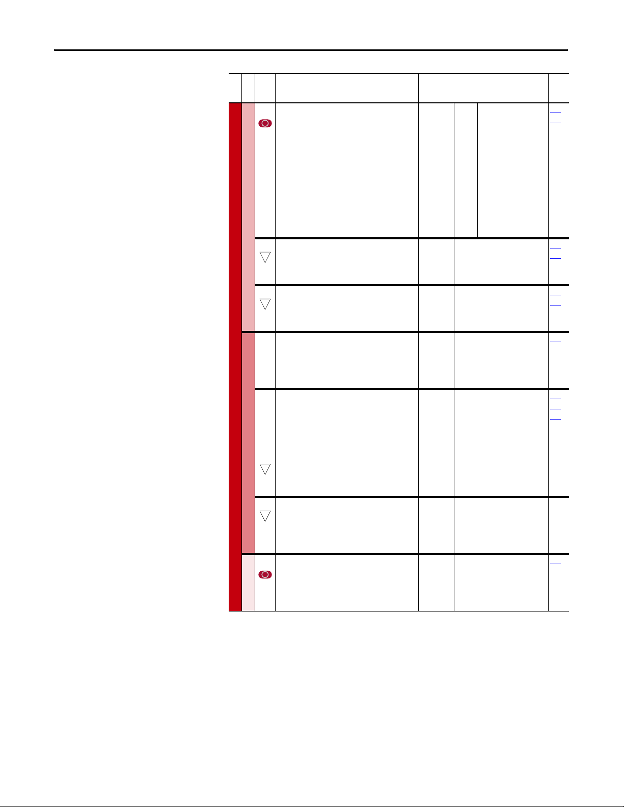
Summary of Changes
This manual contains new and updated information. Changes throughout this
revision are marked by change bars, as shown to the right of this paragraph.
New and Updated Information
This table contains the changes made to this revision.
Top ic Pag e
Updated the description for parameter 465 [Fan Control] to indicate that the
default value has been changed to 1 “Enabled.”
Updated parameter 212 [Drive Alarm 2] to include new bit 8 “Fan Cooling.” 39
Updated parameter 238 [Fault Config 1] to include new bit 14 “Fan Cooling.” 42
Added a note to the description for the “IGBT OverTemp” fault (F9) to specify that
the “IGBT Overtemp” fault is equivalent to the Drive Overload (Software), and is
not adjustable.
Added a note to the “System Fault” (F10) to specify that the fault subcodes are
only available in revision 4.001 or later.
Update the description for the “OverCurrent” fault (F12) to specify that the drive
output current has instantaneously exceeded 360% of the HD rating.
Added a note to the description for the “IGBT Temp HW” fault (F31) to specify
that the “IGBT Temp HW” fault is equivalent to the Drive Instantaneous Overload
(Hardware), and is not adjustable.
Updated the description for the “Fan Cooling” fault (F32) to include information
on configuring a “Fan Cooling” alarm.
32
64
65
65
66
66
Rockwell Automation Publication 20C-PM001F-EN-P - March 2012 3
Page 4

Summary of Changes
Notes:
4 Rockwell Automation Publication 20C-PM001F-EN-P - March 2012
Page 5

Table of Contents
Preface
Drive Start-Up
Programming and Parameters
Who Should Use this Manual . . . . . . . . . . . . . . . . . . . . . . . . . . . . . . . . . . . . . . . 7
What Is Not in this Manual. . . . . . . . . . . . . . . . . . . . . . . . . . . . . . . . . . . . . . . . . 7
Additional Resources . . . . . . . . . . . . . . . . . . . . . . . . . . . . . . . . . . . . . . . . . . . . . . . 8
General Precautions . . . . . . . . . . . . . . . . . . . . . . . . . . . . . . . . . . . . . . . . . . . . . . . . 8
Chapter 1
Prepare For Drive Start-Up . . . . . . . . . . . . . . . . . . . . . . . . . . . . . . . . . . . . . . . 11
Start-Up the Drive . . . . . . . . . . . . . . . . . . . . . . . . . . . . . . . . . . . . . . . . . . . . . . . 12
Chapter 2
About Parameters . . . . . . . . . . . . . . . . . . . . . . . . . . . . . . . . . . . . . . . . . . . . . . . . 15
How Parameters are Organized. . . . . . . . . . . . . . . . . . . . . . . . . . . . . . . . . . . . 17
Monitor File. . . . . . . . . . . . . . . . . . . . . . . . . . . . . . . . . . . . . . . . . . . . . . . . . . . . . 20
Motor Control File. . . . . . . . . . . . . . . . . . . . . . . . . . . . . . . . . . . . . . . . . . . . . . . 21
Speed Command File. . . . . . . . . . . . . . . . . . . . . . . . . . . . . . . . . . . . . . . . . . . . . 24
Dynamic Control File . . . . . . . . . . . . . . . . . . . . . . . . . . . . . . . . . . . . . . . . . . . . 30
Utility File. . . . . . . . . . . . . . . . . . . . . . . . . . . . . . . . . . . . . . . . . . . . . . . . . . . . . . . 35
Communication File . . . . . . . . . . . . . . . . . . . . . . . . . . . . . . . . . . . . . . . . . . . . . 45
Inputs/Outputs File. . . . . . . . . . . . . . . . . . . . . . . . . . . . . . . . . . . . . . . . . . . . . . 49
Parameter Cross Reference – by Name . . . . . . . . . . . . . . . . . . . . . . . . . . . . . 56
Parameter Cross Reference – by Number. . . . . . . . . . . . . . . . . . . . . . . . . . . 58
Troubleshooting
HIM Overview
Chapter 3
Drive Status . . . . . . . . . . . . . . . . . . . . . . . . . . . . . . . . . . . . . . . . . . . . . . . . . . . . . 62
Faults and Alarms . . . . . . . . . . . . . . . . . . . . . . . . . . . . . . . . . . . . . . . . . . . . . . . . 63
Manually Clearing Faults . . . . . . . . . . . . . . . . . . . . . . . . . . . . . . . . . . . . . . . . . 63
Fault and Alarm Descriptions . . . . . . . . . . . . . . . . . . . . . . . . . . . . . . . . . . . . . 64
Fault Subcodes. . . . . . . . . . . . . . . . . . . . . . . . . . . . . . . . . . . . . . . . . . . . . . . . . . . 71
Clearing Alarms. . . . . . . . . . . . . . . . . . . . . . . . . . . . . . . . . . . . . . . . . . . . . . . . . . 77
Common Drive Symptoms and Corrective Actions . . . . . . . . . . . . . . . . . 77
Technical Support Options . . . . . . . . . . . . . . . . . . . . . . . . . . . . . . . . . . . . . . . 79
Appendix A
External and Internal Connections . . . . . . . . . . . . . . . . . . . . . . . . . . . . . . . . 81
LCD Display Elements . . . . . . . . . . . . . . . . . . . . . . . . . . . . . . . . . . . . . . . . . . . 82
ALT Functions . . . . . . . . . . . . . . . . . . . . . . . . . . . . . . . . . . . . . . . . . . . . . . . . . . 82
Menu Structure . . . . . . . . . . . . . . . . . . . . . . . . . . . . . . . . . . . . . . . . . . . . . . . . . . 83
View and Edit Parameters . . . . . . . . . . . . . . . . . . . . . . . . . . . . . . . . . . . . . . . . 85
Remove and Install the HIM. . . . . . . . . . . . . . . . . . . . . . . . . . . . . . . . . . . . . . 86
Rockwell Automation Publication 20C-PM001F-EN-P - March 2012 5
Page 6

Table of Contents
Appendix B
Application Notes
History of Changes
Index
External Brake Resistor . . . . . . . . . . . . . . . . . . . . . . . . . . . . . . . . . . . . . . . . . . . 87
Minimum Speed . . . . . . . . . . . . . . . . . . . . . . . . . . . . . . . . . . . . . . . . . . . . . . . . . 87
Motor Control Technology . . . . . . . . . . . . . . . . . . . . . . . . . . . . . . . . . . . . . . . 88
Motor Overload. . . . . . . . . . . . . . . . . . . . . . . . . . . . . . . . . . . . . . . . . . . . . . . . . . 89
Overspeed . . . . . . . . . . . . . . . . . . . . . . . . . . . . . . . . . . . . . . . . . . . . . . . . . . . . . . . 91
Power Loss Ride Through. . . . . . . . . . . . . . . . . . . . . . . . . . . . . . . . . . . . . . . . . 91
Process PI . . . . . . . . . . . . . . . . . . . . . . . . . . . . . . . . . . . . . . . . . . . . . . . . . . . . . . . 93
Reverse Speed Limit . . . . . . . . . . . . . . . . . . . . . . . . . . . . . . . . . . . . . . . . . . . . . . 96
Skip Frequency. . . . . . . . . . . . . . . . . . . . . . . . . . . . . . . . . . . . . . . . . . . . . . . . . . . 97
Sleep Wake Mode . . . . . . . . . . . . . . . . . . . . . . . . . . . . . . . . . . . . . . . . . . . . . . . . 99
Start At Power Up. . . . . . . . . . . . . . . . . . . . . . . . . . . . . . . . . . . . . . . . . . . . . . . 101
Stop Modes . . . . . . . . . . . . . . . . . . . . . . . . . . . . . . . . . . . . . . . . . . . . . . . . . . . . 101
Appendix C
Changes to This Manual . . . . . . . . . . . . . . . . . . . . . . . . . . . . . . . . . . . . . . . . . 103
6 Rockwell Automation Publication 20C-PM001F-EN-P - March 2012
Page 7

Preface
The purpose of this manual is to provide you with the basic information needed
to start-up, program and troubleshoot the PowerFlex 700H adjustable frequency
AC drive.
For information on… See page…
Who Should Use this Manual Below
What Is Not in this Manual Below
Additional Resources 8
General Precautions 8
Who Should Use this Manual
What Is Not in this Manual
This manual is intended for qualified personnel. You must be able to program
and operate Adjustable Frequency AC drives and related devices. In addition, you
must have an understanding of the parameter settings and functions.
The PowerFlex 700H Programming Manual does not provide installation
instructions or maintenance and repair information.
For installation information, refer to:
• PowerFlex 700S/700H Adjustable Frequency AC Drives, Frames 9…14
Installation Instructions, publication PFLEX-IN006
• PowerFlex 700S/700H IP00 Open Power Structure, Frames 10…14
Installation Instructions, publication PFLEX-IN020
For maintenance and repair information, refer to:
• PowerFlex 700H and 700S Hardware Service Manual, Frame 9, PFLEX-
TG001
• PowerFlex 700H and 700S Hardware Service Manual, Frame 10, PFLEX-
TG002
• PowerFlex 700H and 700S Hardware Service Manual, Frame 11, PFLEX-
TG003
• PowerFlex 700H and 700S Hardware Service Manual, Frame 12, PFLEX-
TG004
• PowerFlex 700H and 700S Hardware Service Manual, Frame 13, PFLEX-
TG005
• PowerFlex 700H and 700S Hardware Service Manual, Frame 14, PFLEX-
TG006
.
.
For detailed drive application information refer to:
• PowerFlex Reference Manual, publication PFLEX-RM001
Rockwell Automation Publication 20C-PM001F-EN-P - March 2012 7
.
Page 8
Preface
Additional Resources
General Precautions
These documents contain additional information concerning related products
from Rockwell Automation.
Resource Description
Industrial Automation Wiring and Grounding Guidelines,
publication 1770-4.1
Preventive Maintenance of Industrial Control and Drive
System Equipment, publication DRIVES-TD001
Safety Guidelines for the Application, Installation and
Maintenance of Solid State Control, publication SGI-1.1
A Global Reference Guide for Reading Schematic Diagrams,
publication 100-2.10
Product Certifications website, http://www.ab.com Provides declarations of conformity, certificates, and
Provides general guidelines for installing a Rockwell
Automation industrial system.
Provides a checklist that can be used as a guide in
performing preventive maintenance of industrial
control and drive system equipment.
Provides general guidelines for the application,
installation, and maintenance of solid-state control.
wiring diagram symbols used throughout various parts
of the world.
other certification details.
You can view or download publications at
http:/www.rockwellautomation.com/literature/
. To order paper copies of
technical documentation, contact your local Allen-Bradley distributor or
Rockwell Automation sales representative.
7
ATTENTION: This drive contains ESD (Electrostatic Discharge) sensitive parts and
assemblies. Static control precautions are required when installing, testing,
servicing or repairing this assembly. Component damage may result if ESD
control procedures are not followed. If you are not familiar with static control
procedures, reference A-B publication 8000-4.5.2, “Guarding Against
Electrostatic Damage” or any other applicable ESD protection handbook.
ATTENTION: An incorrectly applied or installed drive can result in component
damage or a reduction in product life. Wiring or application errors, such as,
undersizing the motor, incorrect or inadequate AC supply, or excessive ambient
temperatures may result in malfunction of the system.
ATTENTION: Only qualified personnel familiar with adjustable frequency AC
drives and associated machinery should plan or implement the installation,
start-up and subsequent maintenance of the system. Failure to comply may
result in personal injury and/or equipment damage.
ATTENTION: To avoid an electric shock hazard, verify that the voltage on the bus
capacitors has discharged completely before servicing. Check the DC bus voltage
at the Power Terminal Block by measuring between the +DC and -DC terminals,
between the +DC terminal and the chassis, and between the -DC terminal and
the chassis. The voltage must be zero for all three measurements.
ATTENTION: Risk of injury or equipment damage exists. DPI host products must
not be directly connected together via 1202 cables. Unpredictable behavior can
result if two or more devices are connected in this manner.
8 Rockwell Automation Publication 20C-PM001F-EN-P - March 2012
Page 9

Preface
ATTENTION: The sheet metal cover and mounting screws on the ASIC Board
located on the power structure are energized at (-) DC bus potential high
voltage. Risk of electrical shock, injury, or death exists if someone comes in
contact with the assembly.
ATTENTION: The “adjust freq” portion of the bus regulator function is extremely
useful for preventing nuisance overvoltage faults resulting from aggressive
decelerations, overhauling loads, and eccentric loads. It forces the output
frequency to be greater than commanded frequency while the drive's bus
voltage is increasing towards levels that would otherwise cause a fault.
However, it can also cause either of the following two conditions to occur.
• Fast positive changes in input voltage (more than a 10% increase within 6
minutes) can cause uncommanded positive speed changes. However an
“OverSpeed Limit” fault will occur if the speed reaches [Max Speed] +
[Overspeed Limit]. If this condition is unacceptable, action should be taken to 1)
limit supply voltages within the specification of the drive and, 2) limit fast
positive input voltage changes to less than 10%. Without taking such actions, if
this operation is unacceptable, the “adjust freq” portion of the bus regulator
function must be disabled (see parameters 161 and 162).
• Actual deceleration times can be longer than commanded deceleration times.
However, a “Decel Inhibit” fault is generated if the drive stops decelerating
altogether. If this condition is unacceptable, the “adjust freq” portion of the bus
regulator must be disabled (see parameters 161 and 162). In addition, installing
a properly sized dynamic brake resistor will provide equal or better performance
in most cases.
Important: These faults are not instantaneous. Test results have shown that they
can take between 2…12 seconds to occur.
Rockwell Automation Publication 20C-PM001F-EN-P - March 2012 9
Page 10

Preface
Notes:
10 Rockwell Automation Publication 20C-PM001F-EN-P - March 2012
Page 11

Chapter 1
Drive Start-Up
This chapter describes how you start up the PowerFlex 700H drive. Refer to
Appendix
For Information on… See page…
Prepare For Drive Start-Up Below
Start-Up the Drive 12
A for a brief description of the LCD Human Interface Module (HIM).
ATTENTION: Power must be applied to the drive to perform the following startup procedure. Some of the voltages present are at incoming line potential. To
avoid electric shock hazard or damage to equipment, only qualified service
personnel should perform the following procedure. Thoroughly read and
understand the procedure before beginning. If an event does not occur while
performing this procedure, Do Not Proceed. Remove Power including user
supplied control voltages. User supplied voltages may exist even when main AC
power is not applied to then drive. Correct the malfunction before continuing.
Prepare For Drive Start-Up
Before Applying Power to the Drive
❏ 1. Confirm that all inputs are connected to the correct terminals and are
secure.
❏ 2. Verify that AC line power at the disconnect device is within the rated value
of the drive.
❏ 3. Verify that control power voltage is correct.
The remainder of this procedure requires that a HIM be installed. If an
operator interface is not available, remote devices should be used to start
up the drive.
Rockwell Automation Publication 20C-PM001F-EN-P - March 2012 11
Page 12

Chapter 1 Drive Start-Up
Apply Power to the Drive
❏ 4. Apply AC power and control voltages to the drive.
Start-Up the Drive
• If the STS (status) LED is NOT flashing green, refer to Drive Status
page 62 for more information.
• If any of the six digital inputs are configured for “Stop – CF” (CF =
Clear Fault) or “Enable,” verify that signals are present or reconfigure
[Digital Inx Sel].
• If an I/O option is not installed (no I/O terminal block is present),
verify that [Digital Inx Sel] is not configured to “Stop – CF” or
“Enable.” If this is not done, the drive will not start. Refer to Fault and
Alarm Descriptions on page 64 for a list of potential digital input
conflicts.
• If a fault code appears, refer to Chapter
❏ 5. Proceed to “Start-Up the Drive”.
The PowerFlex 700H drive is designed so that start up is simple and efficient. If
you have an LCD HIM, two start-up methods are provided, allowing you to
select the desired level needed for the application.
• S.M.A.R.T. Start
This routine allows you to quickly set up the drive by programming values
for the most commonly used functions. See Running S.M.A.R.T. Start
page 13.
3.
on
on
•Assisted Start Up
This routine prompts you for information that is needed to start up a drive
for most applications, such as line and motor data, commonly adjusted
parameters and I/O. See Running an Assisted Start Up
IMPORTANT
Power must be applied to the drive when viewing or changing parameters.
Previous programming may affect the drive status and operation when power
is applied.
on page 13.
12 Rockwell Automation Publication 20C-PM001F-EN-P - March 2012
Page 13
Drive Start-Up Chapter 1
/
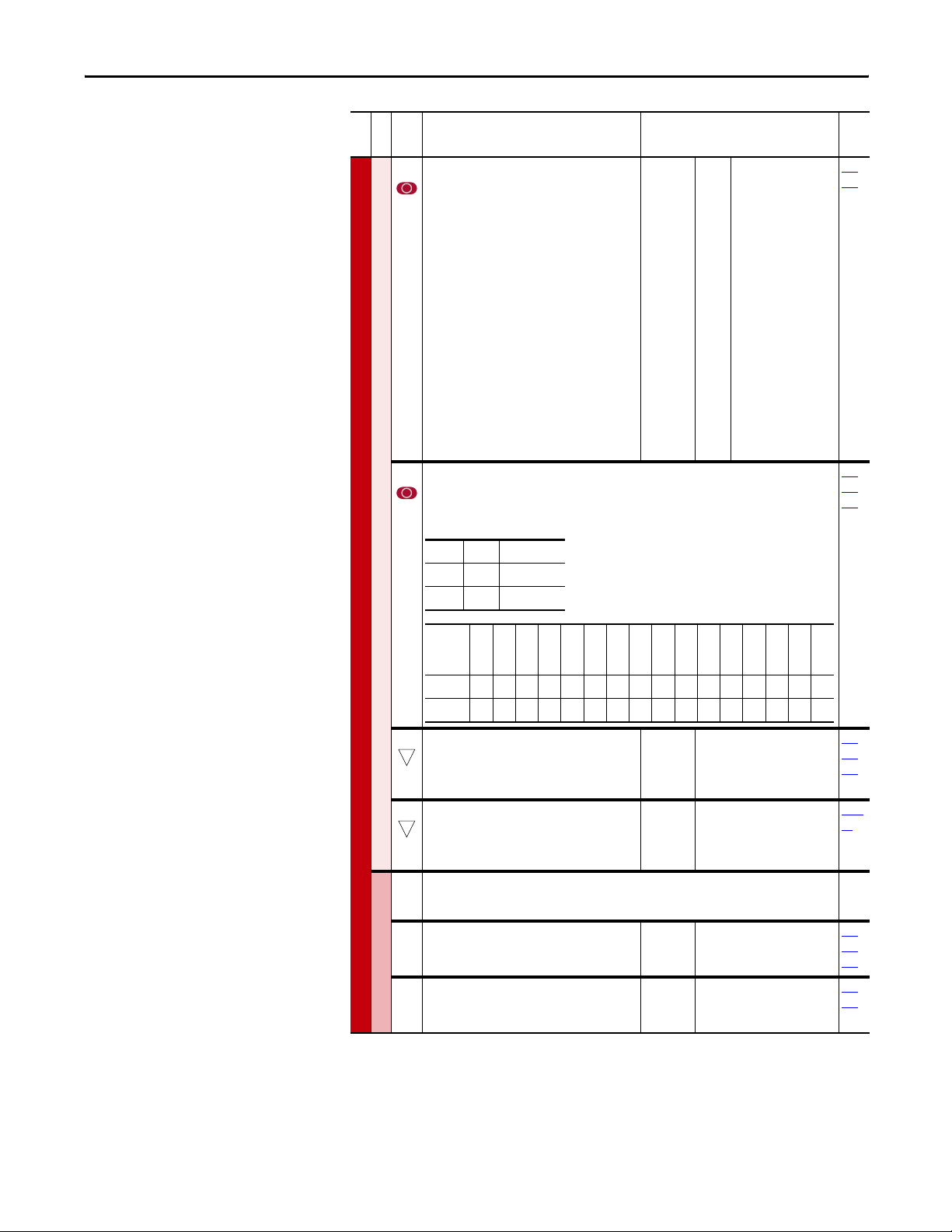
Running S.M.A.R.T. Start
During a Start Up, the majority of applications require changes to only a few
parameters. The LCD HIM on a PowerFlex 700H drive offers S.M.A.R.T. start,
which displays the most commonly changed parameters. With these parameters,
you can set the following functions:
S - Start Source and Stop Mode
M - Minimum and Maximum Speed
A - Accel Time 1 and Decel Time 1
R - Reference Source
T - Thermal Motor Overload
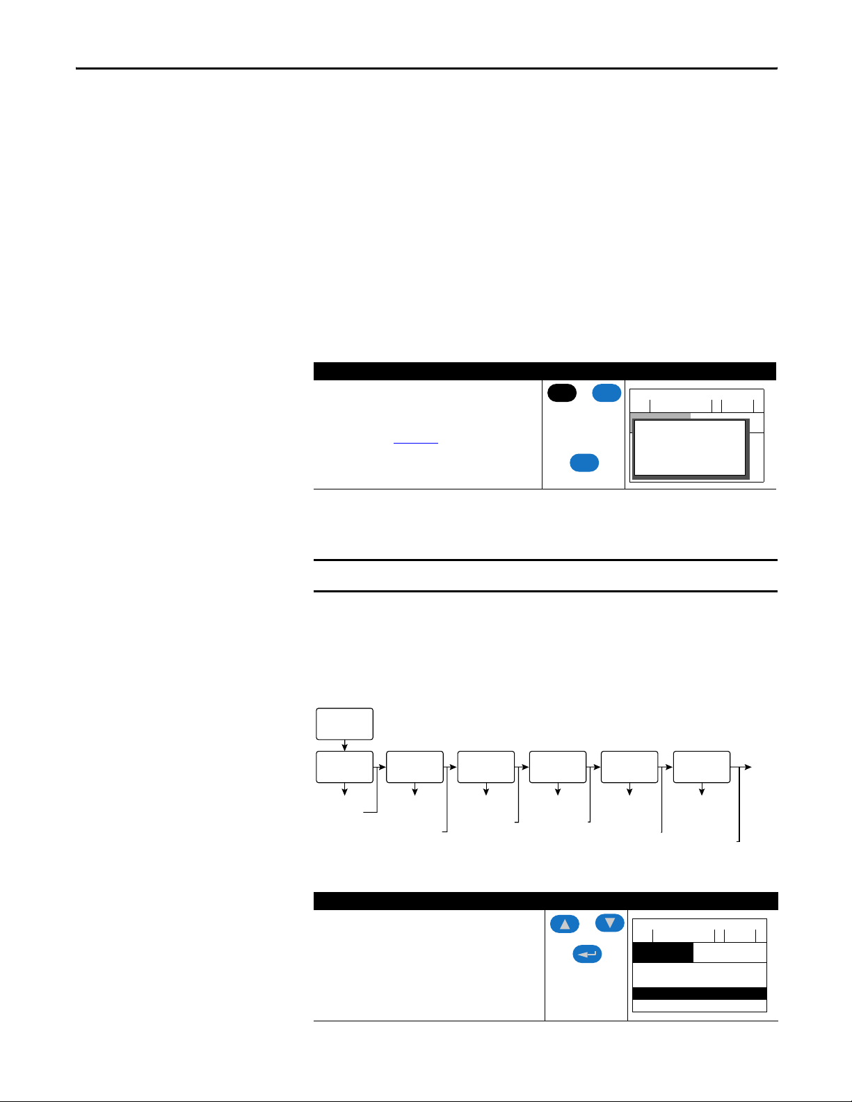
To run a S.M.A.R.T. start routine, follow these instructions:
Step Key(s) Example LCD Displays
1. Press ALT and then Esc (S.M.A.R.T). The S.M.A.R.T. star t
screen appears.
2. View and change parameter values as desired. For HIM
information, see Appendix
A.
3. Press Esc to exit the S.M.A.R.T. star t.
ALT
Esc
Esc
F-> Stopped Auto
0.0
SMART List:
Main Menu:
Digital In2 Sel
Diagnostics
Stop Mode A
Parameter
Minimum Speed
Hz
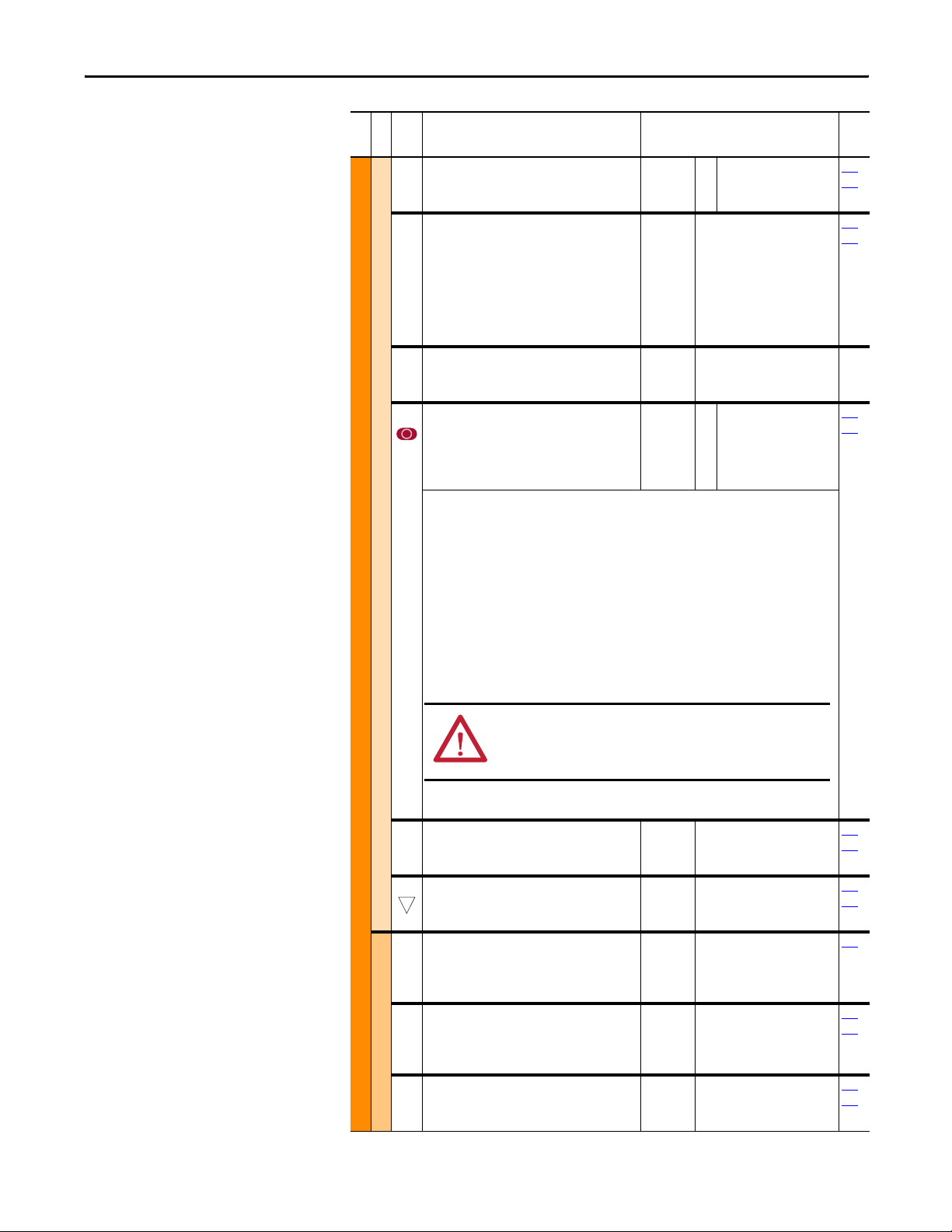
Running an Assisted Start Up
IMPORTANT
The Assisted start-up routine asks simple yes or no questions and prompts you to
input required information. Access Assisted Start Up by selecting “Start Up”
from the Main Menu.
Figure 1 - PowerFlex 700H Start Up Menu
Main Menu:
Start-Up
Input Voltage
Select
Sets Input
Voltage
To perform an Assisted Start-Up, follow these instructions:
Step Key(s) Example LCD Displays
1. In the Main Menu, press the Up Arrow or Down Arrow to
scroll to “Start Up”.
2. Press Enter.
This start-up routine requires an LCD HIM.
Motor Data and
Ramp Times
Enter Motor NP
Data, Stop Mode,
Accel/Decel
Ramp Times
Motor Tests
Optimize Torque
and
Verify Direction
Speed Limits
Set Min/Max
Speed and
Direction Control
Speed/Torque
Control
Configure
Source, Value
and Scale for
Speed References
Digital Inputs/Outputs
F-> Stopped Auto
0.0
Main Menu:
Memory Storage
Start Up
Preferences
Start/Stop/I/O
Configure
Control Method
(2 Wire/3 Wire), I/O,
and Analog Outputs
Hz
Done
Exit
Rockwell Automation Publication 20C-PM001F-EN-P - March 2012 13
Page 14

Chapter 1 Drive Start-Up
Notes:
14 Rockwell Automation Publication 20C-PM001F-EN-P - March 2012
Page 15

Chapter 2
Programming and Parameters
This chapter provides a complete list and description of the PowerFlex 700H
parameters. The parameters can be programmed (viewed/edited) using an LCD
Human Interface Module (HIM). As an alternative, programming can also be
performed using DriveExplorer™ or DriveExecutive™ software and a personal
computer. Refer to HIM Overview
HIM.
For Information on… See page…
About Parameters Below
How Parameters are Organized 17
Monitor File 20
Motor Control File 21
Speed Command File 24
Dynamic Control File 30
Utility File 35
Communication File 45
Inputs/Outputs File 49
Param eter Li st by Na me 56
Parameter List by Number 58
on page 81 for a brief description of the LCD
About Parameters
To configure a drive to operate in a specific way, drive parameters may have to be
changed to values different than the default setting. Three types of parameters
exist:
•ENUM Parameters
ENUM parameters allow a selection from a list of items. The LCD HIM
will display a text message for each item.
•Bit Parameters
Bit parameters have individual bits associated with features or conditions.
If the bit is 0, the feature is off or the condition is false. If the bit is 1, the
feature is on or the condition is true.
•Numeric Parameters
These parameters have a single numerical value (i.e. 0.1 Volts).
Rockwell Automation Publication 20C-PM001F-EN-P - March 2012 15
Page 16
Chapter 2 Programming and Parameters
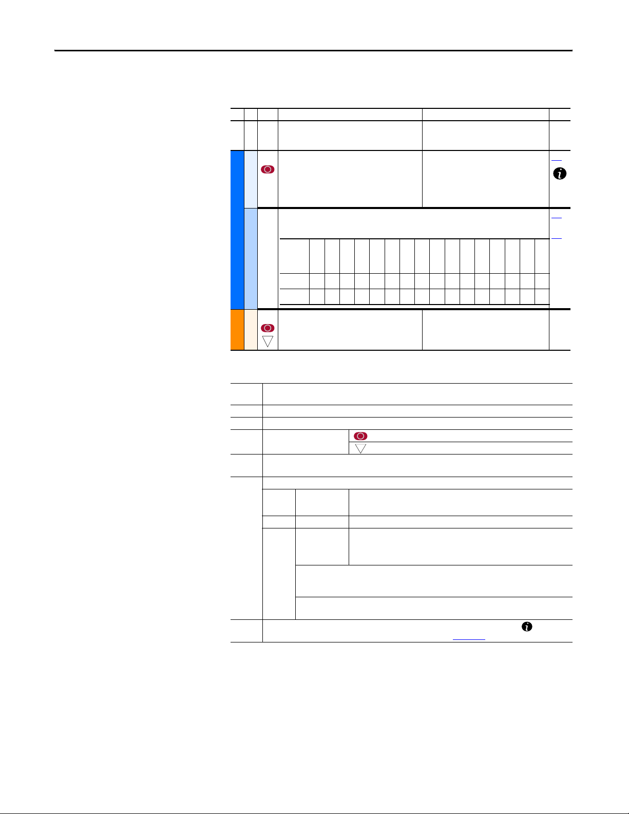
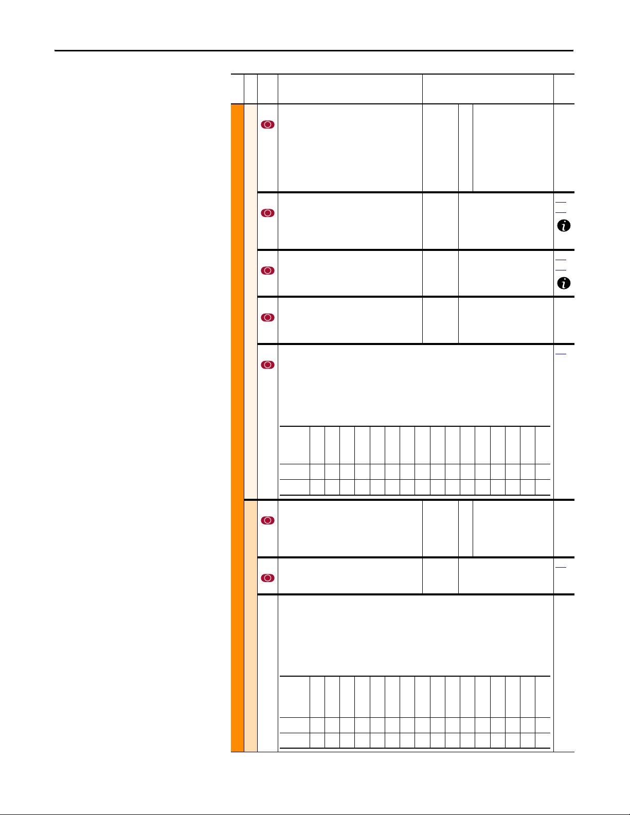
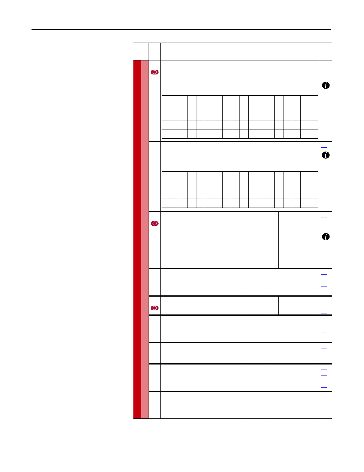
This table is an example of how each parameter type is presented in this manual.
Each numbered column is described in the table following this example.
123 4 5 6
File
Parameter Name & Description Values
Group
No.
198 [Load Frm Usr Set]
Loads a previously saved set of parameter values
from a selected user set location in drive
Drive . . .
nonvolatile memory to active drive memory.
216 [Dig In Status]
Default:
Options:00
“Ready”
“Ready”
“User Set 1”
1
“User Set 2”
2
“User Set 3”
3
Read Only 361
Status of the digital inputs.
UTILITY
Name
Reserved
Reserved
Reserved
Reserved
Reserved
Reserved
Reserved
Reserved
Reserved
Reserved
Digital In6
Digital In5
Digital In4
Digital In3
Diagnostics
044 [Motor NP RPM]
32
MOTOR . . .
Motor Data
Column
Description
Defaultxxxxxxxxxx000000
Bit 1514131211109876543210
Set to the motor nameplate rated RPM.
Default:
Min/Max:
Units:
1750.0 RPM
60.0/19200.0 RPM
1.0 RPM
Digital In2
No.
1File – Lists the major parameter file category.
2Group – Lists the parameter group within a file.
3No. – Parameter number. = Parameter value cannot be changed until drive is stopped.
32
= 32 bit parameter.
4 Parameter Name & Description – Parameter name as it appears on an LCD HIM, with a brief description of
the parameters function. Parameters names appear within square brackets [] throughout this manual.
5Values – Defines the various operating characteristics of the parameter. Three types exist.
ENUM Default:
Options:
Lists the default value assigned at the factory. “Read Only” = no default.
Displays the optional programming selections available.
Bit Bit: Lists the bit name, default setting and place holder for each bit.
Numeric Default:
Min/Max:
Units:
Lists the default value assigned at the factory. “Read Only” = no default.
The range (lowest and highest setting) possible for the parameter.
Unit of measure and resolution as shown on the LCD HIM.
Important: Some parameters will have two unit values:
• Analog inputs can be set for current or voltage with parameter 320 [Anlg In Config].
• Setting parameter 79 [Speed Units] selects “Hz” or “RPM.”
Important: When sending values through DPI ports, simply remove the decimal point to arrive
at the correct value (i.e. to send “5.00 Hz,” use “500”).
6Related – Lists parameters (if any) that interact with the selected parameter. The symbol “ ” indicates
that additional parameter configuration information is available in Appendix
B.
Related
199
thru
366
Digital In1
16 Rockwell Automation Publication 20C-PM001F-EN-P - March 2012
Page 17

Programming and Parameters Chapter 2
How Parameters are Organized
The LCD HIM displays parameters in a File-Group-Parameter or Numbered
List view order. To switch display mode, access the Main Menu, press ALT, then
Sel while the cursor is on the parameter selection. In addition, using [Param
Access Lvl], you can display only the commonly used parameters or all
parameters.
File-Group-Parameter Order View
This view simplifies programming by grouping parameters that are used for
similar functions. The parameters are organized into six files in Basic Parameter
view or seven files in Advanced Parameter view. Each file is divided into groups,
and each parameter is an element in a group. By default, the LCD HIM displays
parameters by File-Group-Parameter view.
Numbered List View
In this view, all parameters are listed in ascending numerical order.
Basic Parameter View
Parameter 196 [Param Access Lvl] set to option 0 “Basic.”
File Group Parameters
Monitor
Monitor
Motor Control
Motor Control
Speed Command
Speed Command
Dynamic Control
Dynamic Control
Utility
Utility
Metering Output Freq 001
Motor Data M otor NP Volts 041
Torq Attributes Motor Cntl Sel 053 Maximum Freq 055 Autotune 061
Spd Mode/Limits Speed Units 079
Speed References Speed Ref A Sel 090
Discrete Speeds Jog Speed 1 100
Ramp Rates Accel Time 1 140
Load Limits Current Lmt Sel 147 Current Lmt Val 148
Stop/Brake Modes Stop/Brk Mode A 155
Restart Modes Start At PowerUp 168 Auto Rstrt Tries 174 Auto Rstrt Delay 175
Power Loss Power Loss Mode 184 Power Loss Time 185 Power Loss Volts 186
Direction Config Direction Mode 190
Drive Memory Param Access Lvl 196
Diagnostics Start Inhibits 214 Dig In Status 216 D ig Out Status 217
Faults Fault Config 1 238
Alarms Alarm Config 1 259
Commanded Speed 002
Speed Reference 023
Motor NP FLA 042
Motor NP Hertz 043
Feedback Select 080
Speed Ref A Hi 091
Speed Ref A Lo 092
Preset Speed 1 101
Preset Speed 2 102
Accel Time 2 141
Stop/Brk Mode B 156
DC Brk Lvl Sel 15 7
Reset To Defalts 197
Commanded Torque 024
Output Current 003
Torque Current 004
Motor NP RPM 044
Motor NP Power 045
Mtr NP Pwr Units 046
Minimum Speed 081
Maximum Speed 082
Speed Ref B Sel 093
Speed Ref B Hi 094
Speed Ref B Lo 095
Preset Speed 3 103
Preset Speed 4 104
Preset Speed 5 105
Decel Time 1 142
Decel Time 2 143
DC Brake Level 158
DC Brake Time 159
Bus Reg Mode A 161
Load Fr m Usr Set 198
Save To User Set 199
DC Bus Voltage 012
Motor OL Hertz 047
Motor Poles 049
Rev Speed Limit 454
TB Man Ref Sel 096
TB Man Ref Hi 097
TB Man Ref Lo 098
Preset Speed 6 106
Preset Speed 7 107
Jog Speed 2 108
S-Curve % 146
Bus Reg Mode B 162
DB Resistor Type 163
Language 201
Rockwell Automation Publication 20C-PM001F-EN-P - March 2012 17
Page 18

Chapter 2 Programming and Parameters
File Group Parameters
Inputs/Outputs
Inputs & Outputs
Analog Inputs Anlg In Config 320
Analog Outputs Analog Out1, 2 Sel 342
Digital Inputs Digital In1 Sel 361
Digital Outputs Digital Out1 Sel 380
Analog In1 Hi 322
Analog Out1 Hi 343
Digital In2 Sel 362
Digital In3 Sel 363
Digital Out2 Sel 384
Analog In1 Lo 323
Analog In2 Hi 325
Analog Out1, 2 Lo 344
Analog Out1, 2 Sel 345
Digital In4 Sel 364
Digital In5 Sel 365
Digital In6 Sel 366
Digital Out3 Sel 388
Dig Out1 Level 381
Advanced Parameter View
Parameter 196 [Param Access Lvl] set to option 1 “Advanced.”
File Group Parameters
Monitor
Monitor
Motor Control
Motor Control
Speed Command
Speed Command
Dynamic Control
Dynamic Control
Metering Output Freq 001
Drive Data Rated kW 026
Motor Data Mo tor Type 040
Torq Attributes Motor Cntl Sel 053
Commanded Speed 002
Ramped Speed 022
Speed Reference 023
Commanded Torque 024
Output Current 003
Torque Current 004
Rated Volts 027
Motor NP Volts 041
Motor NP FLA 042
Motor NP Hertz 043
Maximum Freq 055
Flux Up Mode 057
Volts per Hertz Start/Acc Boost 069 Break Voltage 071 Break Frequency 072
Spd Mode/Limits Speed Units 079
Speed References Speed Ref A Sel 090
Discrete Speeds Jog Speed 1 100
Speed Trim Trim In Select 117
Feedback Select 080
Minimum Speed 081
Maximum Speed 082
Speed Ref A Hi 091
Speed Ref A Lo 092
Preset Speed 1 101
Preset Speed 2 102
Tri m Ou t Se le ct 1 18
Slip Comp Sli p RPM @ FLA 121 Slip RPM Meter 123
Process PI PI Configuration 124
Ramp Rates Accel Time 1 140
Load Limits Current Lmt Sel 147
Stop/Brake Modes Stop/Brk Mode A 155
Restart Modes Start At PowerUp 168
Power Loss Power Loss Mode 184
PI Control 125
PI Reference Sel 126
PI Setpoint 12 7
PI Feedback Sel 128
PI Integral Time 129
PI Prop Gain 130
Accel Time 2 141
Current Lmt Val 148
Stop/Brk Mode B 156
DC Brk Lvl Sel 15 7
DC Brake Level 158
DC Brake Time 159
Flying Start En 169
Auto Rstrt Tries 174
Auto Rstrt De lay 175
Power Lo ss Time 185
Flux Current 005
Output Voltage 006
Output Power 007
Output Powr Fctr 008
Elapsed MWh 009
Elapsed Run Time 010
MOP Reference 011
Rated Amps 028 Control SW Ver 029
Motor NP RPM 044
Motor NP Power 045
Mtr NP Pwr Units 046
Motor OL Hertz 047
Flux Up Tim e 058
SV Boost Filter 059
Autotune 061
Overspeed Limit 083
Skip Frequency 1 084
Skip Frequency 2 085
Skip Frequency 3 086
Speed Ref B Sel 093
Speed Ref B Hi 094
Speed Ref B Lo 095
Preset Speed 3 103
Preset Speed 4 104
Preset Speed 5 105
Tri m Hi 11 9
Tri m Lo 120
PI Lower Limit 131
PI Upper Limit 132
PI Preload 133
PI Status 134
PI Ref Meter 135
PI Fdback Meter 136
PI Error Meter 137
Decel Time 1 142
Decel Time 2 143
Current Lmt Gain 149
Drive OL Mode 150
Bus Reg Ki 160
Bus Reg Mode A 161
Bus Reg Mode B 162
DB Resistor Type 163
Bus Reg Kp 164
Sleep Wake Mode 178
Sleep Wake Ref 179
Wake Level 18 0
Wake Time 18 1
Power Loss Volts 186 Shear Pin Time 189
Analog In2 Lo 32 6
Analog Out2 Hi 346
Analog Out1, 2 Lo 347
20C-DG1 Remove 358
20C-DG1 Status 359
Dig Out2 Level 385
Dig Out3 Level 389
DC Bus Voltage 012
DC Bus Memory 013
Analog In1 Value 016
Analog In2 Value 017
Speed Reference 023
Speed Feedback 025
Motor OL Factor 0 48
Motor Poles 049
Motor OL Mode 050
IR Voltage Drop 062
Flux Current Ref 063
Compens ation 056
Skip Freq Band 087
Speed/Torque Mod 088
Rev Speed Limit 454
TB Man Ref Sel 096
TB Man Ref Hi 097
TB Man Ref Lo 098
Preset Speed 6 106
Preset Speed 7 107
Jog Speed 2 108
Trim % Setpoint 116
PI Output Meter 138
PI Reference Hi 460
PI Reference Lo 461
PI Feedback Hi 462
PI Feedback Lo 463
PI Output Gain 464
S Curve % 146
PWM Frequency 151
Droop RPM @ FLA 152
Bus Reg Kd 165
DB While Stopped 145
Fan C ontro l 465
Sleep Level 182
Sleep Time 183
Powerup Delay 167
18 Rockwell Automation Publication 20C-PM001F-EN-P - March 2012
Page 19

File Group Parameters
Utility
Utility
Direction Config Direction Mode 190
HIM Ref Config Save HIM Ref 192 Man Ref Preload 193
MOP Config Save MOP Ref 194 MOP Rate 195
Communication
Communication
Inputs/Outputs
Inputs & Outputs
Drive Memory Param Access Lvl 196
Diagnostics Drive Status 1 209
Faults Fault Config 1 238
Alarms Alarm Config 1 259
Comm Contr ol Drive Logic R slt 271
Masks/Owners Logic Mask 276
Datalinks Data In A1 300
Security Port Mask Act 595
Analog Inputs Anlg In Config 320
Analog Outputs Anlg Out Config 340
Digital Inputs Digital In1 Sel 361
Digital Outputs Digital Out1 Sel 380
Reset To Defalts 197
Load Fr m Usr Set 198
Save To User Set 199
Drive Status 2 210
Drive Alarm 1 211
Drive Alarm 2 212
Speed Ref Source 213
Start Inhibits 214
Last Stop Source 215
Dig In Status 216
Faul t Cle ar 24 0
Fault Clear Mode 241
Power Up Marker 242
Fault 1 Code 243
Fault 2 Code 245
Fault 3 Code 247
Fault 4 Code 249
Fault 5 Code 251
Fault 6 Code 253
Alarm Clear 261
Alarm1 Code 262
Alarm2 Code 263
Drive Ref Rslt 272
Start Mask 277
Jog Mask 278
Direction Mask 279
Reference Mask 280
Accel Mask 281
Decel Mask 282
Data In A2 301
Data In B1 302
Data In B2 303
Data In C1 304
Data In C2 305
Write Mask Cfg 596
Anlg In Sqr Root 321
Analog In1 Hi 322
Anlg Out Absolut 341
Analog Out1 Sel 342
Analog Out2 Sel 345
Digital In2 Sel 362
Digital In3 Sel 363
Dig Out1 Level 381
Dig Out1 OnTime 382
Dig Out1 OffTime 383
Digital Out2 Sel 384
Programming and Parameters Chapter 2
Reset Meters 200
Language 201
Voltage Class 202
Drive Checksum 203
Dig Out Status 217
Drive Temp 218
Motor OL Count 220
Fault Frequency 224
Fault Amps 225
Fault Bus Volts 226
Status 1 @ Fault 227
Status 2 @ Fault 228
Fault 7 Code 255
Fault 8 Code 257
Fault 1 Time 244
Fault 2 Time 246
Fault 3 Time 248
Fault 4 Time 250
Fault 5 Time 252
Fault 6 Time 254
Fault 7 Time 256
Fault 8 Time 258
Alarm3 Code 264
Alarm4 Code 265
Alarm5 Code 266
Alarm6 Code 267
Drive Ramp Rslt 273
DPI Port Sel 274
Fault Clr Mask 283
MOP Mask 284
Local Mask 285
Stop Owner 288
Start Owner 289
Jog Owner 290
Direction Owner 291
Data In D1 306
Data In D2 307
Data Out A1 310
Data Out A2 311
Data Out B1 312
Data Out B2 313
Write Mask Act 597 Logic Mask Act 598
Analog In2 Hi 325
Analog In1 Lo 323
Analog In2 Lo 326
Analog Out1 Hi 343
Analog Out2 Hi 346
Analog Out1 Lo 344
Analog Out2 Lo 347
Digital In4 Sel 364
Digital In5 Sel 365
Digital In6 Sel 366
Dig Out2 Level 385
Dig Out2 OnTime 386
Dig Out2 OffTime 387
Digital Out3 Sel 388
Dig Out3 Level 389
Dyn UserSet Cnfg 204
Dyn UserSet Sel 205
Dyn UserSet Actv 206
Alarm 1 @ Fault 229
Alarm 2 @ Fault 230
Testpoint 1 Sel 234
Testpoint 1 Data 235
Testpoint 2 Sel 236
Testpoint 2 Data 237
Faul t 1 Su bCod e 54 3
Faul t 2 Su bCod e 54 5
Faul t 3 Su bCod e 54 7
Faul t 4 Su bCod e 54 9
Faul t 5 Su bCod e 55 1
Faul t 6 Su bCod e 55 3
Faul t 7 Su bCod e 55 5
Faul t 8 Su bCod e 55 7
Alarm7 Code 268
Alarm8 Code 269
DPI Port Value 275
Reference Owner 292
Accel Owner 293
Decel Owner 294
Fault Clr Owner 295
MOP Owner 296
Local Own er 297
Data Out C1 314
Data Out C2 315
Data Out D1 316
Data Out D2 317
Analog In1 Loss 324
Analog In2 Loss 327
Anlg Out1 Scal 354
Anlg Out2 Scal 355
Anlg1 Out Setpt 377
Anlg2 Out Setpt 378
20C-DG1 Remove 358
20C-DG1 Status 359
Dig Out3 OnTime 390
Dig Out3 OffTime 391
Dig Out Setpt 379
Rockwell Automation Publication 20C-PM001F-EN-P - March 2012 19
Page 20

Chapter 2 Programming and Parameters
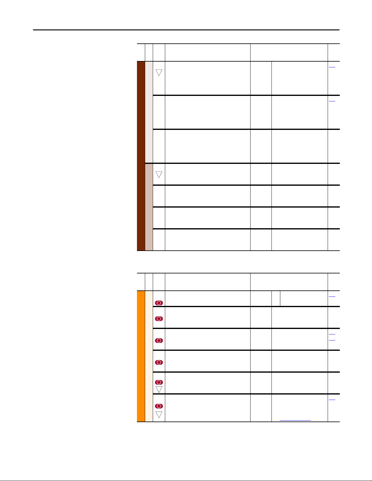
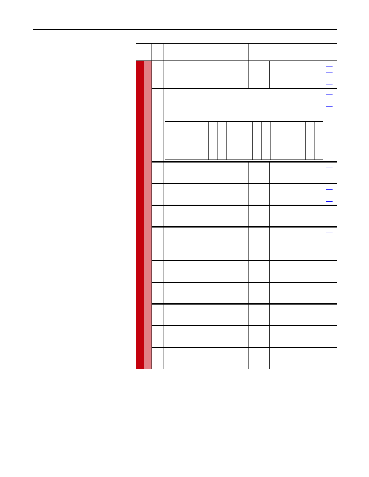
Monitor File
File
Parameter Name & Description Values
Group
No.
001 [Outp ut Freq]
Output frequency present at U/T1, V/T2 & W/T3.
002 [Commanded Speed]
32
Value of the active Speed/Frequency Reference.
Displayed in Hz or RPM, depending on value of
[Speed Units].
003 [Output Current]
The total output current present at U/T1, V/T2 &
W/T3.
004 [Torque Current]
Based on the motor, the amount of current that is
in phase with the fundamental voltage
component.
005 [Flux Current]
Amount of current that is out of phase with the
fundamental voltage component.
006 [Outp ut Voltag e]
Output voltage present at terminals U/T1, V/T2 &
W/T3.
007 [Output Power]
Output power present at U/T1, V/T2 & W/T3.
008 [Outp ut Powr Fctr]
Output power factor.
009 [Elapsed MWh]
Metering
MONITOR
32
Accumulated output energy of the drive.
010 [Elapsed Run Time]
32
Accumulated time drive is outputting power.
011 [MOP Reference]
32
Value of the signal at MOP (Motor Operated
Potentiometer).
012 [DC Bus Voltage]
Present DC bus voltage level.
013 [DC Bus Memory]
Approximate full load DC bus voltage level.
016
[Analog In1 Value]
017
[Analog In2 Value]
Value of the signal at the analog inputs.
022 [Ramped Speed]
32
Value of commanded speed after Accel/Decel, and
S-Curve are applied.
Default:
Min/Max:
Units:
Default:
Min/Max:
Units:
Default:
Min/Max:
Units:
Default:
Min/Max:
Units:
Default:
Min/Max:
Units:
Default:
Min/Max:
Units:
Default:
Min/Max:
Units:
Default:
Min/Max:
Units:
Default:
Min/Max:
Units:
Default:
Min/Max:
Units:
Default:
Min/Max:
Units:
Default:
Min/Max:
Units:
Default:
Min/Max:
Units:
Default:
Min/Max:
Units:
Default:
Min/Max:
Units:
Read Only
–/+ [Maximum Freq]
0.1 Hz
Read Only
–/+ [Maximum Speed]
0.1 Hz
0.1 RPM
Read Only
0.0/Drive Rated Amps x 2
0.1 Amps
Read Only
Drive Rating x –2/+2
0.1 Amps
Read Only
Drive Rating x –2/+2
0.1 Amps
Read Only
0.0/Drive Rated Volts
0.1 VAC
Read Only
0.0/Drive Rated kW x 2
0.1 kW
Read Only
0.00/1.00
0.01
Read Only
0.0/429496729.5 MWh
0.1 MWh
Read Only
0.0/214748364.0 Hrs
0.1 Hrs
Read Only
–/+ [Maximum Speed]
0.1 Hz
0.1 RPM
Read Only
0.0/Based on Drive Rating
0.1 VDC
Read Only
0.0/Based on Drive Rating
0.1 VDC
Read Only
0.000/20.000 mA
–/+10.000V
0.001 mA
0.001 Volt
Read Only
–/+320.0 Hz
–/+19200.0 RPM
0.1 Hz
0.1 RPM
Related
079
079
079
20 Rockwell Automation Publication 20C-PM001F-EN-P - March 2012
Page 21
Programming and Parameters Chapter 2
File
Parameter Name & Description Values
Group
No.
023 [Speed Reference]
32
Summed value of ramped speed, process PI and
droop.
024 [Commanded Torque]
Final torque refe rence value after limits and
filtering are applied. Percent of motor rated
Metering
torque.
Note: Added for firmware revision 4.001.
025 [Speed Feedback]
This parameter displays the estimated value of
actual motor speed.
MONITOR
026 [Rated kW]
32
Drive power rating.
027 [Rated Volts]
The drive input voltage class (208, 240, 400 etc.).
028 [Rated Amps]
Drive Data
The drive rated output current.
029 [Control SW Ver]
Main Control Board software revision.
Default:
Min/Max:
Units:
Default:
Min/Max:
Units:
Default:
Min/Max:
Units:
Default:
Min/Max:
Units:
Default:
Min/Max:
Units:
Default:
Min/Max:
Units:
Default:
Min/Max:
Units:
Read Only
–/+320.0 Hz
–/+19200.0 RPM
0.1 Hz
0.1 RPM
Read Only
–/+800.0%
0.1%
Read Only
–/+320.0 Hz
–/+19200.0 RPM
0.1 Hz
0.1 RPM
Read Only
0.00/3000.00 kW
0.01 kW
Read Only
0.0/690.0 VAC
0.1 VAC
Read Only
0.0/6553.5 Amps
0.1 Amps
Read Only
0.000/255.255
0.001
Related
079
053
Motor Control File
File
Parameter Name & Description Values
Group
No.
040 [Motor Type]
Set to match the type of motor connected.
041 [Motor NP Volts]
Set to the motor nameplate rated volts.
042 [Motor NP FLA]
Set to the motor nameplate rated full load amps.
043 [Motor NP Hertz]
Set to the motor nameplate rated frequency.
Motor Data
MOTOR CONTROL
044 [Motor NP RPM]
Set to the motor nameplate rated RPM.
32
045 [Motor NP Power]
Set to the motor nameplate rated power.
32
Default:
Options:00
Default:
Min/Max:
Units:
Default:
Min/Max:
Units:
Default:
Min/Max:
Units:
Default:
Min/Max:
Units:
Default:
Min/Max:
Units:
“Induction”
“Induction”
Based on Drive Rating
0.0/[Rated Volts]
0.1 VAC
Based on Drive Rating
0.0/[Rated Amps] × 2
0.1 Amps
Based on Drive Rating
5.0/320.0 Hz
0.1 Hz
Based on Drive Rating
60.0/19200.0 RPM
1.0 RPM
Based on Drive Rating
0.00/5000.00
0.01 kW/HP
See [Mtr NP Pwr Units]
Related
053
047
048
046
Rockwell Automation Publication 20C-PM001F-EN-P - March 2012 21
Page 22
Chapter 2 Programming and Parameters
File
Parameter Name & Description Values
Group
No.
046 [Mtr NP Pwr Units]
Selects the motor power units to be used.
“Convert H P” = converts all power units to
Horsepower.
“Convert kW” = converts al l power units to
kilowatts.
Note: This parameter does not get changed with a
“Reset to Defaults”.
047 [Motor OL Hertz]
Selects the output frequency below which the
motor operating current is derated. The motor
thermal overload will generate a fault at lower
levels of current below this output frequency.
048 [Motor OL Factor]
Sets the operating level for the motor overload.
Motor
FLAOLFactor
049 [Motor Poles]
Motor Data
Defines the number of poles in the motor.
Note: Maximum value changed from 12 to 18 for
firmware revision 4.001.
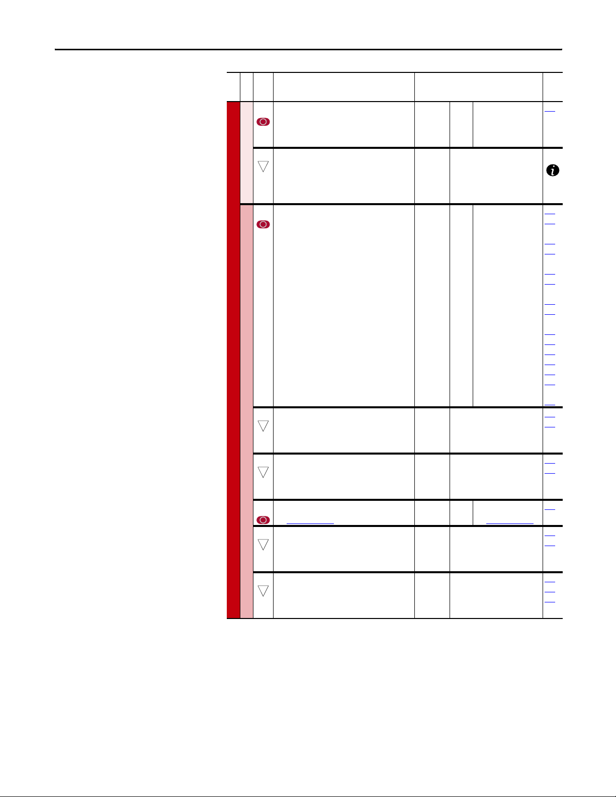
050 [Motor OL Mode]
“Pwr Cyc Ret” - If “0”, the value of parameter 220 [Motor OL Count] is reset to zero by a drive reset
or power cycle. If “1”, the value of parameter 220 [Motor OL Count] is maintained. A “1” to “0”
transition resets parameter 220 [Motor OL Count] to zero.
Note: Added for firmware revision 3.001.
1 = Enabled
0 = Disabled
Related
Default:
Options:–0
Default:
Min/Max:
Units:
Default:
Min/Max:
x
Level
Operating
=
Units:
Default:
Min/Max:
Units:
Based on Drive Rating
“Horsepower”
“kiloWatts”
1
“Convert HP”
2
“Convert kW”
3
Motor NP Hz/3
0.0/Motor NP Hz
0.1 Hz
1.00
0.20/2.00
0.01
4
2/18
1 Pole
042
220
042
220
220
MOTOR CONTROL
053 [Motor Cntl Sel]
Sets the method of motor control used in the
drive.
055 [Maximum Freq]
Sets the highest frequency the drive will output.
Refer to parameter 083 [Overspeed Limit].
056 [Compensation]
“Mtr Lead Rev” - If “1”, reverses the phase rotation of the applied voltage, effectively reversing
the motor leads.
Notes: Not retained when the parameters are reset to defaults. Added for firmware revision
3.001.
Torq Attributes
1 = Enabled
0 = Disabled
Name
Reserved
Reserved
Reserved
Reserved
Reserved
Reserved
Reserved
Reserved
Reserved
Reserved
Reserved
Reserved
Reserved
Reserved
Reserved
Pwr Cyc Ret
Defaultxxxxxxxxxxxxxxx0
Bit 1514131211109876543210
Default:
Options:00
Default:
Min/Max:
Units:
Name
Reserved
Reserved
Reserved
Reserved
Reserved
Reserved
Reserved
Reserved
Reserved
Defaultxxxxxxxxxx0xxxxx
Bit 1514131211109876543210
“Sensrls Vect”
“Sensrls Vect”
1
“SV Economize”
2
“Custom V/Hz”
3
“Fan/Pmp V/Hz”
Based on Drive Rating
5.0/320.0 Hz
0.1 Hz
Reserved
Mtr Lead Rev
Reserved
Reserved
Reserved
Reserved
Reserved
083
22 Rockwell Automation Publication 20C-PM001F-EN-P - March 2012
Page 23
Programming and Parameters Chapter 2
File
Group
No.
057 [Flux Up Mode]
058 [Flux Up Time]
059 [SV Boost Filter]
061 [Autotune]
Torq Attributes
MOTOR CONTROL
Parameter Name & Description Values
Flux is established for [Flux Up Time] before
Default:
Options:00
“Manual”
“Manual”
acceleration.
Sets the amount of time the drive will use to try
and achieve full motor stator flux. When a Start
Default:
Min/Max:
Units:
0.2 Secs
0.0/5.0 Secs
0.1 Secs
command is issued, DC current at current limit
level is used to build stator flux before
accelerating. This will occur unless [Rated Amps]
is less than [Motor NP FLA], then only 81% of
drive rated current is used.
55
0/32767
1
“Calcul ate”
“Ready”
“Static Tune”
1
“Rotate Tune”
2
“Calcul ate”
3
Sets the amount of filtering used to boost voltage
during Sensorless Vector operation.
Provides a manual or automatic method for
setting [IR Voltage Drop], and [Flux Current Ref].
Note: Program parameter 053 [Motor Cntl Sel]
prior to running an autotune.
Default:
Min/Max:
Units:
Default:
Options:30
“Ready” (0) = Parameter returns to this setting following a “Static Tune” or “Rotate Tune.” It also
permits manually setting [IR Voltage Drop], [Ixo Voltage Drop] and [Flux Current Ref].
“Static Tune” (1) = A temporary command that initiates a non-rotational motor stator resistance
test for the best possible automatic setting of [IR Voltage Drop], [Break Voltage] and [Break
Frequency] in all modes. A start command is required within 20 seconds following initiation of
this setting. The parameter returns to “Ready” (0) following the test, at which time another start
transition is required to operate the drive in normal mode. Used when motor cannot be rotated.
“Rotate Tune” (2) = A temporary command that initiates a “Static Tune” followed by a rotational
test for the best possible automatic setting of [Flux Current Ref] and [Start Boost]. A start
command is required following initiation of this setting. The parameter returns to “Ready” (0)
following the test, at which time another start transition is required to operate the drive in
normal mode. Important: Used when motor is uncoupled from the load. Results may not be
valid if a load is coupled to the motor during this procedure.
Related
053
058
053
058
053
062
ATT EN TI ON : Rotation of the motor in an undesired direction can occur during
this procedure. To guard against possible injury and/or equipment damage, it
is recommended that the motor be disconnected from the load before
proceeding.
“Calculate” (3) = This setting uses motor nameplate data to automatically set [IR Voltage Drop],
[Flux Current Ref] and [Slip RPM @ FLA].
062 [IR Voltage Drop]
Value of voltage drop across the resistance of the
motor stator at rated motor current.
063 [Flux Current Ref]
32
Value of amps for full motor flux.
069 [Start Boost]
Sets the voltage boost level for starting and
acceleration. Refer to parameter 083 [Overspeed
Default:
Min/Max:
Units:
Default:
Min/Max:
Units:
Default:
Min/Max:
Units:
Based on Drive Rating
0.0/[Motor NP Volts]×0.50
0.1 VAC
Based on Drive Rating
0.00/[Motor NP FLA]
0.01 Amps
Based on Drive Rating
0.0/[Motor NP Volts] × 0.25
0.1 VAC
Limit].
071 [Break Voltage]
Sets the voltage the drive will output at [Break
Frequency]. Refer to parameter 083 [Overspeed
Volts p er Hertz
Limit].
072 [Break Frequency]
Sets the frequency the drive will output at [Break
Voltage]. Refer to parameter 083.
Default:
Min/Max:
Units:
Default:
Min/Max:
Units:
Based on Drive Rating
0.0/[Motor NP Volts]
0.1 VAC
Based on Drive Rating
0.0/[Maximum Freq]
0.1 Hz
053
061
053
061
053
053
072
053
071
Rockwell Automation Publication 20C-PM001F-EN-P - March 2012 23
Page 24
Chapter 2 Programming and Parameters
Speed Command File
File
Parameter Name & Description Values
Group
No.
079 [Speed Units]
Selects the units to be used for all speed related
parameters. Options 0 & 1 indicate status only.
Options 2 & 3 will convert/configure the drive for
that selection.
“Convert Hz” (2) - converts all speed based
parameters to Hz, and changes the value
proportionately (i.e. 1800 RPM = 60 Hz).
“Convert RPM” (3) - converts all speed based
parameters to RPM, and changes the value
proportionately.
Note: This parameter does not get changed with a
“Reset to Defaults”.
080 [Feedback Select]
Selects the source for motor speed feedback.
“Open Loop” (0) - no encoder is present, and slip
compensation is not needed.
“Slip Comp” (1) - tight speed control is needed,
and encoder is not present.
081 [Minimum Speed]
Sets the low limit for speed reference after scaling
32
is applied. Refer to parameter 083 [Overspeed
Limit].
082 [Maximum Speed]
Sets the high limit for speed reference after
32
scaling is applied. Refer to parameter 083
[Overspeed Limit].
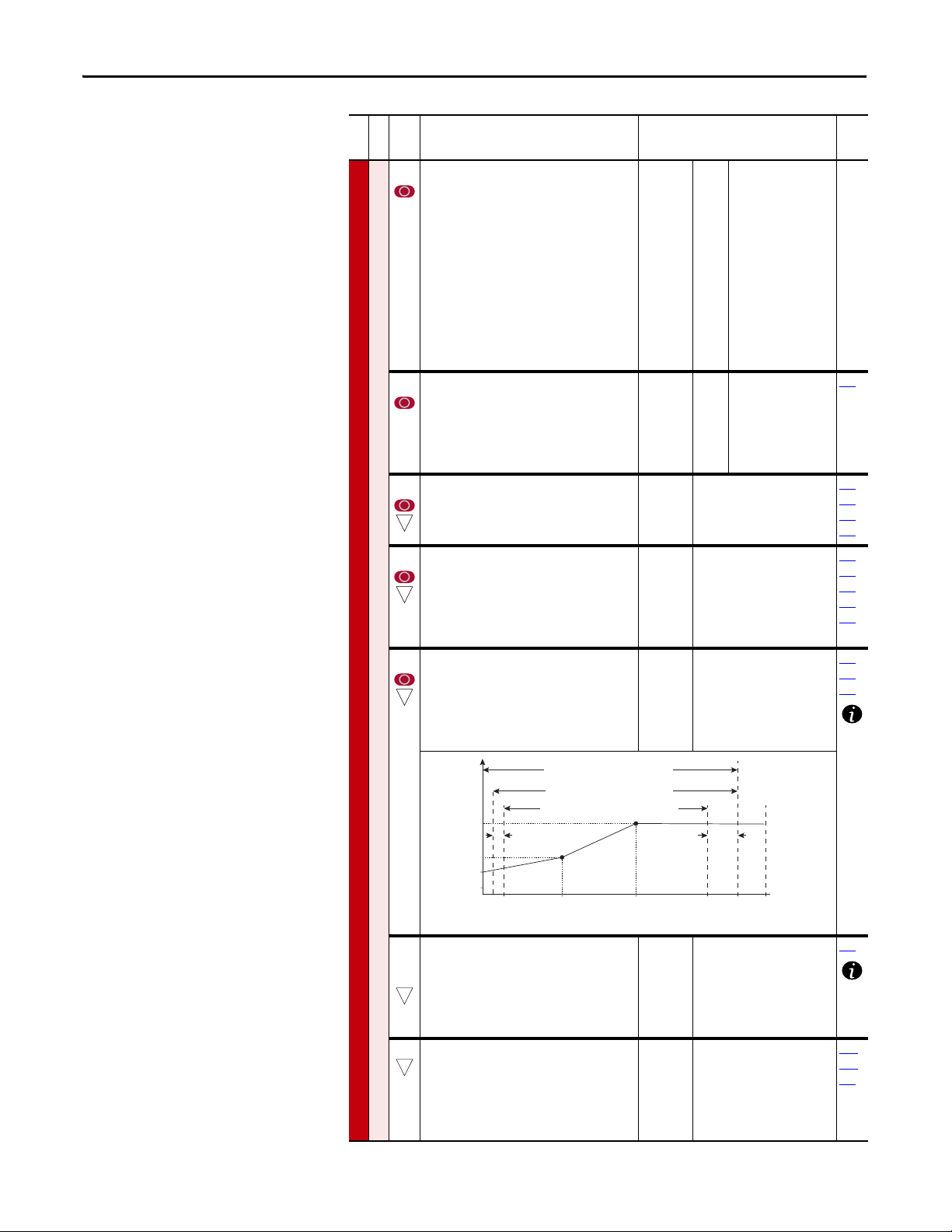
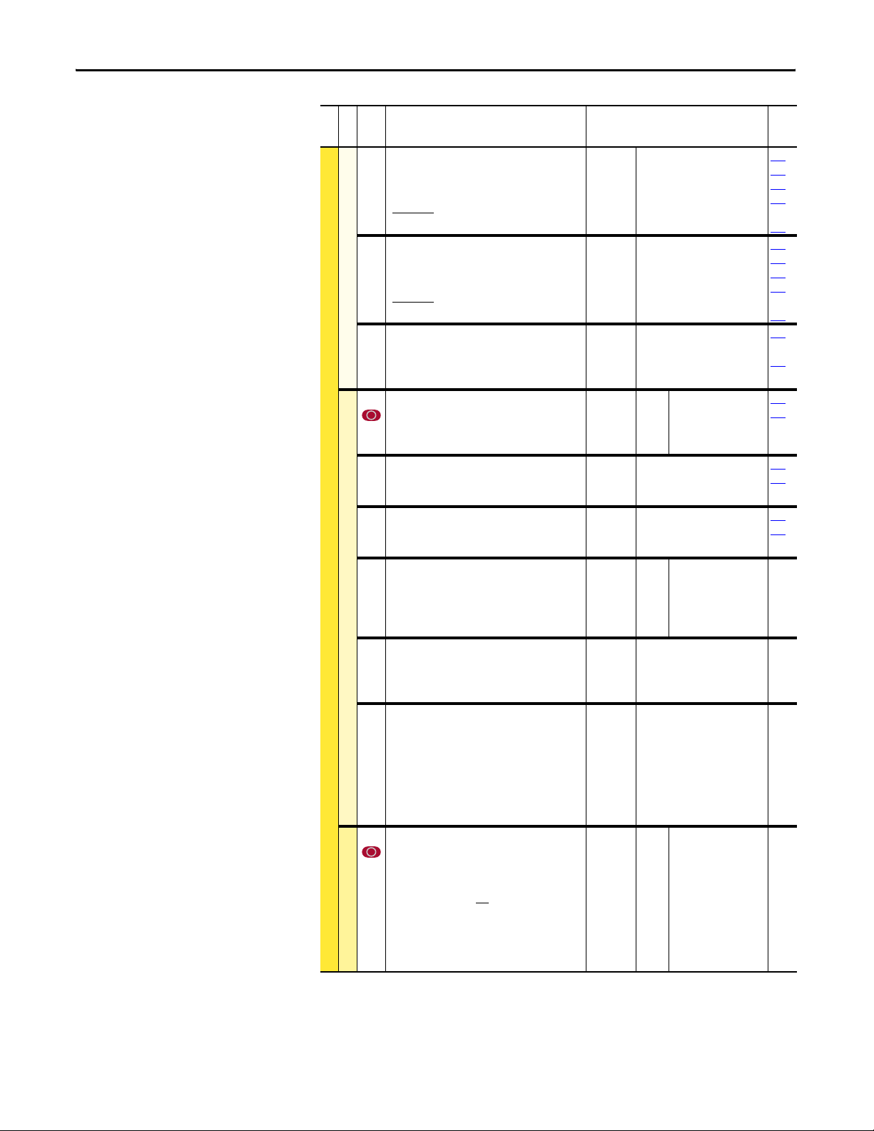
083 [Overspeed Limit]
Sets the incremental amount of the output
Spd Mode/Limits
SPEED COMMAND
32
frequency (above [Maximum Speed]) allowable
for functions such as slip compensation.
[Maximum Speed] + [Overspeed Limit] must be
≤[Maximum Freq]
Motor Volts
Voltage
Break Volts
Start Boost
Allowable Output Frequency Range
Bus Regulation or Current Limit
Allowable Output Frequency Range
Normal Operation
Allowable Reference Frequency Range
Frequency Trim due to
Speed Control Mode
Default:
Options:00
Default:
Options:00
Default:
Min/Max:
Units:
Default:
Min/Max:
Units:
Default:
Min/Max:
Units:
Overspeed
Limit
“Hz”
“Hz”
1
“RPM”
2
“Convert Hz”
3
“Convert RPM”
“Open Loop”
“Open Loop”
1
“Slip Comp”
0.0
0.0/[Maximum Speed]
0.1 Hz
0.1 RPM
50.0 or 60.0 Hz (volt class)
[Motor NP RPM]
5.0/320.0 Hz
75.0/19200.0 RPM
0.1 Hz
0.1 RPM
10.0 Hz
300.0 RPM
0.0/20.0 Hz
0.0/600.0 RPM
0.1 Hz
0.1 RPM
Related
152
079
083
092
095
055
079
083
091
094
055
079
082
0 Min
Speed
084
[Skip Frequency 1]
085
[Skip Frequency 2]
086
[Skip Frequency 3]
32
Sets a frequency at which the drive will not
Break
Frequency
operate. [Skip Frequency x] and [Skip Frequency
Band] must not equal 0.
087 [Skip Freq Band]
32
Determines the bandwidth around a skip
frequency. [Skip Freq Band] is split, applying 1/2
above and 1/2 below the actual skip frequency.
The same bandwidth applies to all skip
frequencies.
24 Rockwell Automation Publication 20C-PM001F-EN-P - March 2012
Motor
Hz
Frequency
Default:
Default:
Default:
Min/Max:
Units:
Default:
Min/Max:
Units:
Max
Output
Speed
Freq Limit
Based on Drive Rating
0.0 Hz
0.0 Hz
–/+[Maximum Speed]
0.1 Hz
0.0 Hz
0.0/30.0 Hz
0.1 Hz
Max
Freq
087
084
085
086
Page 25
Programming and Parameters Chapter 2
File
Parameter Name & Description Values
Group
No.
088 [Speed/Torque Mod]
Selec ts the torque reference source.
“Speed Reg” (1) - drive operates as a speed
regulato r.
454 [Rev Speed Limit]
32
Sets a limit on speed in the negative direction.
Spd Mode/Limits
Used in bipolar mode only. A value of zero
disables this parameter and uses [Min Speed] for
minimum speed.
090 [Speed Ref A Sel]
Selects the source of the speed reference to the
drive unless [Speed Ref B Sel] or [Preset Speed 17] is selected.
(1)
See Installation Manual for DPI port locations.
SPEED COMMAND
091 [Speed Ref A Hi]
32
Scales the upper value of the [Speed Ref A Sel]
Speed References
selection when the source is an analog input.
092 [Speed Ref A Lo]
32
Scales the lower value of the [Speed Ref A Sel]
selection when the source is an analog input.
093 [Speed Ref B Sel]
See [Speed Ref A Sel]
094 [Speed Ref B Hi]
32
Scales the upper value of the [Speed Ref B Sel]
selection when the source is an analog input.
095 [Speed Ref B Lo]
32
Scales the lower value of the [Speed Ref B Sel]
selection when the source is an analog input.
Related
Default:
Options:11
Default:
Min/Max:
“Speed Reg”
“Speed Reg”
0.0 RPM
–[Max Speed]/0.0 Hz
053
–[Max Speed]/0.0 RPM
Units:
0.0 Hz
0.0 RPM
2
3-8
9
10
11
12
13
14
15
16
17
18
19
20
21
22
“Analog In 2”
“Analog In 1”
“Analog In 2”
“Reserved”
“MOP Level”
“Reserved”
“Preset Spd1”
“Preset Spd2”
“Preset Spd3”
“Preset Spd4”
“Preset Spd5”
“Preset Spd6”
“Preset Spd7”
“DPI Port 1”
“DPI Port 2”
“DPI Port 3”
“DPI Port 4”
“DPI Port 5”
002
091
thru
093
101
thru
107
117
thru
120
192
thru
194
(1)
(1)
(1)
(1)
(1)
213
272
273
320
361
thru
Default:
Options:21
366
Default:
Min/Max:
Units:
Default:
Min/Max:
Units:
Default:
.
Options:
Default:
Min/Max:
Units:
Default:
Min/Max:
Units:
Based on Drive Rating
–/+[Maximum Speed]
0.1 Hz
0.01 RPM
0.0
–/+[Maximum Speed]
0.1 Hz
0.01 RPM
11 “Preset Spd1”
See [Speed Ref A Sel]
Based on Drive Rating
–/+[Maximum Speed]
0.1 Hz
0.01 RPM
0.0
–/+[Maximum Speed]
0.1 Hz
0.01 RPM
079
082
079
081
090
079
093
079
090
093
Rockwell Automation Publication 20C-PM001F-EN-P - March 2012 25
Page 26
Chapter 2 Programming and Parameters
File
Parameter Name & Description Values
Group
No.
096 [TB Man Ref Sel]
Sets the manual speed reference source when a
digital input is configured for “Auto/Manual.”
Note: Options 18…20 were added for firmware
revision 5.002.
(1)
Speed References
097 [TB Man Ref Hi]
32
Scales the upper value of the [TB Man Ref Sel]
selection when the source is an analog input.
098 [TB Man Ref Lo]
32
Scales the lower value of the [TB Man Ref Sel]
selection when the source is an analog input.
100 [Jog Speed 1]
Sets the output frequency when Jog Speed 1 is
selected.
SPEED COMMAND
[Preset Speed 1]
101
[Preset Speed 2]
102
[Preset Speed 3]
103
[Preset Speed 4]
104
[Preset Speed 5]
105
[Preset Speed 6]
106
[Preset Speed 7]
107
Discrete Speeds
32
Provides an internal fixed speed command value.
In bipolar mode direction is commanded by the
sign of the referen ce.
108 [Jog Speed 2]
32
Sets the output frequency when Jog Speed 2 is
selected.
116 [Trim % Setpoint]
Adds or subtracts a percentage of the speed
reference or maximum speed. Dependent on the
setting of parameter 118 [Trim Out Select].
Speed Trim
Note: Added for firmware revision 3.001.
“Analog In 2” is not a valid selection if it was
selected for any of the following:
- [Trim In Select]
- [PI Feedback Sel]
- [PI Reference Sel]
- [Current Lmt Sel]
- [Sleep Wake Ref]
Default:
Options:11
Default:
Min/Max:
Units:
Default:
Min/Max:
Units:
Default:
Min/Max:
Units:
Default:
Min/Max:
Units:
Default:
Min/Max:
Units:
Default:
Min/Max:
Units:
“Analog In 1”
“Analog In 1”
“Analog In 2”
2
3…8
“Reserved”
9
“MOP Level”
18
“DPI Port1”
19
“DPI Port2”
20
“DPI Port3”
Based on Drive Rating
–/+[Maximum Speed]
0.1 Hz
0.01 RPM
0.0
–/+[Maximum Speed]
0.1 Hz
0.01 RPM
10.0 Hz
300.0 RPM
–/+[Maximum Speed]
0.1 Hz
1 RPM
5.0 Hz/150 RPM
10.0 Hz/300 RPM
20.0 Hz/600 RPM
30.0 Hz/900 RPM
40.0 Hz/1200 RPM
50.0 Hz/1500 RPM
Based on Drive Rating
–/+[Maximum Speed]
0.1 Hz
1 RPM
10.0 Hz
300.0 RPM
–/+[Maximum Speed]
0.1 Hz
1 RPM
0.0%
–/+200%
0.1%
Related
097
098
(1)
079
096
079
096
079
079
090
093
118
26 Rockwell Automation Publication 20C-PM001F-EN-P - March 2012
Page 27
Programming and Parameters Chapter 2
File
Parameter Name & Description Values
Group
No.
117 [Trim In Select]
Specifies which analog input signal is being used
as a trim input.
(1)
118 [Trim Out Select]
Specifies which speed references are to be trimmed and allows you to trim the speed reference
based on a percentage or the frequency of the input signal.
Note: Added bit 2 “Add or %” for firmware revision 3.001.
Speed Trim
See Installation Manual for DPI port locations.
Value Bit 2 Bit 1, 0
1 = % Trimmed
0 = Add Not Trimmed
Default:
Options:20
1
2
3-8
9
10
11
12
13
14
15
16
17
18
19
20
21
22
“Analog In 2”
“Setpoint”
“Analog In 1”
“Analog In 2”
“Reserved”
“MOP Level”
“Reserved”
“Preset Spd1”
“Preset Spd2”
“Preset Spd3”
“Preset Spd4”
“Preset Spd5”
“Preset Spd6”
“Preset Spd7”
“DPI Port 1”
“DPI Port 2”
“DPI Port 3”
“DPI Port 4”
“DPI Port 5”
Related
090
093
(1)
(1)
(1)
(1)
(1)
117
119
120
SPEED COMMAND
119 [Trim Hi]
32
120 [Trim Lo]
32
121 [Slip RPM @ FLA]
Slip Comp
123 [Slip RPM Meter]
Name
Reserved
Reserved
Reserved
Reserved
Reserved
Reserved
Reserved
Reserved
Reserved
Reserved
Reserved
Reserved
Reserved
Add or %
Tri m Re f B
Defaultxxxxxxxxxxxxx000
Bit 1514131211109876543210
Based on Drive Rating
–/+[Maximum Speed]
0.1 Hz
1 RPM
0.0 Hz
–/+[Maximum Speed]
0.1 Hz
1 RPM
Scales the upper value of the [Trim In Select]
selection when the source is an analog input.
Scales the lower value of the [Trim In Select]
selection when the source is an analog input.
Default:
Min/Max:
Units:
Default:
Min/Max:
Units:
Important: Parameters in the Slip Comp Group are used to enable and tune the Slip
Compensation Regulator. In order to allow the Slip Compensation Regulator to control drive
operation, parameter 080 [Feedback Select] must be set to 1 “Slip Comp”.
Based on [Motor NP RPM]
0.0/1200.0 RPM
0.1 RPM
Read Only
–/+300.0 RPM
0.1 RPM
Sets the amount of compensation to drive output
at motor FLA.
Displays the present amount of adjustment being
applied as slip compensation.
Default:
Min/Max:
Units:
Default:
Min/Max:
Units:
Tri m Re f A
079
082
117
0791
17
061
080
123
080
121
Rockwell Automation Publication 20C-PM001F-EN-P - March 2012 27
Page 28
Chapter 2 Programming and Parameters
File
Parameter Name & Description Values
Group
No.
124 [PI Configuration]
Sets configuration of the PI regulator.
Note: Added bit 9 “% of Ref” for firmware revision 3.001.
1 = Enabled
0 = Disabled
Defaultxxxxxx0x00000000
Bit 1514131211109876543210
125 [PI Control]
Controls the PI regulator.
1 = Enabled
0 = Disabled
Defaultxxxxxxxxxxxxx000
Bit 1514131211109876543210
126 [PI Reference Sel]
Selects the source of the PI reference.
Process PI
SPEED COMMAND
127 [PI Setpoint]
Provides an internal fixed value for process
setpoint when [PI Reference Sel] is set to “PI
Setpoint.”
128 [PI Feedback Sel]
Selects the source of the PI feedback.
129 [PI Integral Time]
Time required for the integral component to reach
100% of [PI Error Meter]. Not functional when the
PI Hold bit of [PI Control] = “1” (enabled).
130 [PI Prop Gain]
Sets the value for the PI proportional component.
PI Error x PI Prop Gain = PI Output
131 [PI Lower Limit]
Sets the lower limit of the PI output.
132 [PI Upper Limit]
Sets the upper limit of the PI output.
Name
Name
Related
124
thru
138
Reserved
Reserved
Reserved
Reserved
Reserved
Reserved
% of Ref
Reserved
Anti-Wind Up
Stop Mode
Feedbak Sqrt
Zero Clamp
Ramp Ref
Preload Mode
Invert Error
Excl Mode
080
Reserved
Reserved
Reserved
Reserved
Reserved
Reserved
Reserved
Reserved
Reserved
Reserved
Reserved
Reserved
Reserved
PI Reset
PI Hold
PI Enable
Default:
Options:00
Default:
Min/Max:
Units:
Default:
Options:
Default:
Min/Max:
Units:
Default:
Min/Max:
Units:
Default:
Min/Max:
Units:
Default:
Min/Max:
Units:
“PI Setpoint”
“PI Setpoint”
“Analog In 1”
1
“Analog In 2”
2
“Reserved”
3-8
“MOP Level”
9
“Master Ref ”
10
“Preset Spd1-7”
11-17
“DPI Port 1-5”
18-22
50.0%
–/+100.0% of Maximum
Process Value
0.1%
2“Analog In 2”
See [PI Reference Sel]
2.0 Secs
0.00/100.00 Secs
0.01 Secs
1.0
0.00/100.00
0.01
–[Maximum Freq]
100%
–/+800.0%
0.1%
+[Maximum Freq]
100%
–/+800.0%
0.1%
124
thru
138
124
thru
138
124
thru
.
138
124
thru
138
124
thru
138
079
124
thru
138
079
124
thru
138
28 Rockwell Automation Publication 20C-PM001F-EN-P - March 2012
Page 29
Programming and Parameters Chapter 2
File
Parameter Name & Description Values
Group
No.
133 [PI Preload]
Sets the value used to preload the integral
component on start or enable.
134 [PI Status]
Status of the Process PI regulator.
1 = Condition True
0 = Condition False
Defaultxxxxxxxxxxxx0000
Bit 1514131211109876543210
135 [PI Ref Meter]
Pres ent va lue of the PI reference signal.
136 [PI Fdback Meter]
Pres ent va lue of the PI feedback signal.
137 [PI Error Meter]
Present value of the PI error.
Process PI
SPEED COMMAND
138 [PI Output Meter]
Present value of the PI output.
460 [PI Reference Hi]
Scales the upper value of [PI Reference Sel] of the
source.
461 [PI Reference Lo]
Scales the lower value of [PI Reference Sel] of the
source.
462 [PI Feedback Hi]
Scales the upper value of [PI Feedback] of the
source.
463 [PI Feedback Lo]
Scales the lower value of [PI Feedback] of the
source.
464 [PI Output Gain]
Sets the gain factor for [PI Output Meter].
Note: Added for firmware revision 3.001.
Name
Related
Default:
Min/Max:
Units:
0.0 Hz
100%
–/+800.0%
0.1%
079
124
thru
138
Read Only 124
thru
138
Reserved
Reserved
Reserved
Reserved
Reserved
Reserved
Reserved
Reserved
Reserved
Reserved
Reserved
Reserved
PI InLimit
PI Reset
PI Hold
PI Enabled
Default:
Min/Max:
Units:
Default:
Min/Max:
Units:
Default:
Min/Max:
Units:
Default:
Min/Max:
Units:
Read Only
–/+100.0%
0.1%
Read Only
–/+100.0%
0.1%
Read Only
–/+100.0%
0.1%
Read Only
–/+100.0 Hz
–/+100.0%
0.1 Hz
124
thru
138
124
thru
138
124
thru
138
124
thru
138
0.1%
Default:
Min/Max:
Units:
Default:
Min/Max:
Units:
Default:
Min/Max:
Units:
Default:
Min/Max:
Units:
Default:
Min/Max:
Units:
100.0%
–/+100.0%
0.1%
–100.0%
–/+100.0%
0.1%
100.0%
–/+100.0%
0.1%
0.0%
–/+100.0%
0.1%
1.000
–/+8.000
0.001
138
Rockwell Automation Publication 20C-PM001F-EN-P - March 2012 29
Page 30
Chapter 2 Programming and Parameters
Dynamic Control File
File
Parameter Name & Description Values
Group
No.
140
[Accel Time 1]
141
[Accel Time 2]
Sets rate of accel for all speed increases.
Max Speed
Accel Time
142
[Decel Time 1]
143
[Decel Time 2]
Sets rate of decel for all speed decreases.
Ramp Rates
Max Speed
Decel Time
146 [S Curve %]
Sets the percentage of accel or decel time that is
applied to the ramp as S Curve. Time is added, 1/2
at the beginning and 1/2 at the end of the ramp.
147 [Current Lmt Sel]
Selects the source for the adjustment of current
limit (i.e. parameter, analog input, etc.).
148 [Current Lmt Val]
Defines the current limit value when [Current Lmt
Sel] = “Cur Lim Val.”
149 [Current Lmt Gain]
Sets the responsiveness of the current limit.
150 [Drive OL Mode]
DYNAMIC CONTROL
Selects drive response to increasing drive
temperature.
Load Limits
151 [PWM Frequency]
Sets the carrier frequency for the PWM output.
Drive derating may occur at higher carrier
frequencies.
152 [Droop RPM @ FLA]
Selects amount of droop that the speed reference
is reduced when at full load torque. Zero disables
the droop function.
=
=
Accel Rate
Decel Rate
Default:
Min/Max:
Units:
Default:
Min/Max:
Units:
Default:
Min/Max:
Units:
Default:
Options:00
Default:
Min/Max:
Units:
Default:
Min/Max:
Units:
Default:
Options:30
Default:
Min/Max:
Units:
Default:
Min/Max:
Units:
10.0 Secs
10.0 Secs
0.1/3276.7 Secs
0.1 Secs
10.0 Secs
10.0 Secs
0.1/3276.7 Secs
0.1 Secs
0%
0/100%
1%
“Cur Lim Val”
“Cur Lim Val”
“Analog In 1”
1
“Analog In 2”
2
Based on Drive Rating
Based on Drive Rating
0.1 Amps
10000
0/32767
1
“Both-PWM 1st”
“Reserved”
“Reduce Clim”
1
“Reserved”
2
“Both-PWM 1st”
3
1.5 kHz or 2 kHz based on Drive
Rating
1/Based on Drive Rating
1 kHz
0.0 RPM
0.0/200.0 RPM
0.1 RPM
Related
142
143
146
361
thru
366
140
141
146
361
thru
366
140
thru
143
146
149
147
149
147
148
Important: Selecting “Slip Comp” with
parameter 080 in conjunction with parameter
152, may produce undesirable results.
145 [DB While Stopped]
Enables/disables dynamic brake operation when
drive is stopped. DB may operate if input voltage
becomes too high.
• Disa bled = DB will not
operate when the drive
is stopped.
• Enabled = DB may operate whenever drive is
Stop/Brake Modes
energized.
Notes: This parameter is used for frame 9 drives
only. Added for firmware revision 3.001.
30 Rockwell Automation Publication 20C-PM001F-EN-P - March 2012
Default:
Options:00
“Disabled”
“Disabled”
“Enabled”
1
Page 31

Programming and Parameters Chapter 2
File
Parameter Name & Description Values
Group
No.
155
[Stop/Brk Mode A]
156
[Stop/Brk Mode B]
Active stop mode. [Stop Mode A] is active unless
[Stop Mode B] is selec ted by inputs.
(1)
information.
(2)
Attention statements at [DC Brake Level].
157 [DC Brake Lvl Sel]
Selects the source for [DC Brake Level].
158 [DC Brake Level]
Defines the DC brake current level injected into
the motor when “DC Brake” is selected as a stop
mode.
The DC braking voltage used in this function is
created by a PWM algorithm and may not
generate the smooth holding force needed for
some applications.
Refer to Stop Modes on page 101 for important
When using options 1 or 2, refer to the
ATT EN TI ON : If a hazard of injury due to movement of equipment or material
exists, an auxiliary mechanical braking device must be used.
ATT EN TI ON : This feature should not be used with synchronous or permanent
magnet motors. Motors may be demagnetized during braking.
Default:
Default:
Options:
Default:
Options:00
Default:
Min/Max:
Units:
“Ramp”
1
0
0
1
2
3
(1)
“Coast”
(1)
“Coast”
(2)
“Ramp”
“Ramp to Hold”
“DC Brake”
“DC Brake Lvl”
“DC Brake Lvl”
1
“Analog In 1”
2
“Analog In 2”
Based on the Drive Rating
0/[Rated Amps]
0.1 Amps
Related
157
158
159
(2)
155
156
158
159
159 [DC Brake Time]
Stop/Brake Modes
DYNAMIC CONTROL
160 [Bus Reg Ki]
161
162
Sets the amount of time DC brake current is
“injected” into the motor.
Sets the responsiveness of the bus regulator.
[Bus Reg Mode A]
[Bus Reg Mode B]
Sets the method and sequence of the DC bus
voltage regulator. Choices are dynamic brake,
frequency adjust or both. Options 2 & 3 only
appear when a dynamic brake is installed in the
drive.
Dynamic Brake Setup:
If a dynamic brake resistor is connected to the
drive, both of these parameter s must be set to
either option 2 or 3.
Refer to the Attention statement on page 8
for
important information on bus regulation.
ATT EN TI ON : The drive does not offer protection for externall y mounted brake
resistors. A risk of fire exists if external braking resistors are not protected.
External resistor packages must be self-protected from over temperature or
the protective circuit shown in Figure 3 on page 87
supplied.
Default:
Min/Max:
Units:
Default:
Min/Max:
Units:
Default:
Options:
0.0 Secs
0.0/90.0 Secs
0.1 Secs
Based on Drive Rating
0/5000
1
“Ad ju st Fre q”
1
“Disabled”
0
“Disabled”
0
“Ad ju st Fre q”
1
“Dynamic Brak”
2
“Both-DB 1st”
3
(or equivalent) must be
155
thru
158
161
162
160
163
163 [DB Resistor Type]
Selects whether an external DB resistor will be
used.
Default:
Options:00
1
“None”
“None”
“External Res”
161
162
Note: Used for frame 9 drives only.
Rockwell Automation Publication 20C-PM001F-EN-P - March 2012 31
Page 32

Chapter 2 Programming and Parameters
File
DYNAMIC CONTROL
Parameter Name & Description Values
Group
No.
164 [Bus Reg Kp]
Proportional gain for the bus regulator. Used to
adjust regulator response.
165 [Bus Reg Kd]
Derivative gain for the bus regulator. Used to
control regulator overshoot.
465 [Fan Control]
Enables/Disables the drive cooling fan control.
“Disabled” = Drive cooling fan control off - fan(s)
always runs
Stop/Brake Modes
“Enabled” = Drive cooling fan control on - the
cooling fan(s) stops if the drive is stopped and the
heatsink temperature is below 55° C for 60
seconds
Note: Added for firmware revision 4.001. Changed
the default value to 1 “Enabled” for firmware
revision 6.001.
167 [Powerup Delay]
Defines the programmed delay time, in seconds,
before a start command is accepted after a power
up.
168 [Start At PowerUp]
Enables/disables a feature to issue a Start or Run
command and automatically resume running at
commanded speed after drive input power is
restored. Requires a digital input configured for
Run or Start and a valid start contact.
Default:
Min/Max:
Units:
Default:
Min/Max:
Units:
Default:
Options:10
Default:
Min/Max:
Units:
Default:
Options:00
Based on Drive Rating
0/10000
1
122
0/10000
1
“Enabled”
“Disabled”
1
“Enabled”
0.0 Secs
0.0/30.0 Secs
0.1 Secs
“Disabled”
“Disabled”
1
“Enabled”
Related
ATT EN TI ON : Equipment damage and/or personal injury may result if this
parameter is used in an inappropriate application. Do not use this function
without considering applicable local, national and international codes,
standards, regulations or industry guidelines.
169 [Flying Start En]
Enables/disables the function which reconnects
Restart Modes
to a spinning motor at actual RPM when a start
command is issued.
174 [Auto Rstrt Tries]
Sets the maximum number of times the drive
attempts to reset a fault and restart.
ATT EN TI ON : Equipment damage and/or personal injury may result if this
parameter is used in an inappropriate application. Do not use this function
without considering applicable local, national and international codes,
standards, regulations or industry guidelines.
175 [Auto Rstrt Delay]
Sets the time between restart attempts when
[Auto Rstrt Tries] is set to a value other than zero.
Default:
Options:00
Default:
Min/Max:
Units:
Default:
Min/Max:
Units:
“Disabled”
“Disabled”
“Enabled”
1
0
0/9
1
1.0 Secs
0.5/30.0 Secs
0.1 Secs
175
174
32 Rockwell Automation Publication 20C-PM001F-EN-P - March 2012
Page 33

Programming and Parameters Chapter 2
File
Parameter Name & Description Values
Group
No.
178 [Sleep Wake Mode]
Enables/disables the Sleep/Wake function.
Important: When enabled, the following
conditions must be met:
• A proper minimum value must be
• A speed reference must be selected in [Speed
• At least one of the following must be
Note: Option 2 was added for firmware revision
2.001.
Conditions Required to Start Drive
Input After Power-Up After a Drive Fault After a Stop Command
Stop Stop Closed
Enable Enable Closed
Run
Run For.
Run Rev.
Restart Modes
DYNAMIC CONTROL
(1)
(2)
(3)
(4)
(5)
(6)
179 [Sleep Wake Ref]
Selects the source of the input controlling the
Sleep Wake function.
180 [Wake Level]
Defines the analog input level that will start the
drive.
181 [Wake Time]
Defines the amount of time at or above [Wake
Level] before a Start is issued.
182 [Sleep Level]
Defines the analog input level that will stop the
drive.
183 [Sleep Time]
Defines the amount of time at or below [Sleep
Level] before a Stop is issued.
1
2
“Disabled”
“Disabled”
“Direct” (Enabled)
“Invert”
Default:
Options:00
programmed for [Sleep Level].
Ref A Sel].
programmed (and input closed) in [Digital Inx
Sel]; “Enable,” “Stop=CF,” “Run,” “Run
Forward,” “Run Reverse.”
ATT EN TI ON : Enabling the Sleep Wake function can cause unexpected machine
operation during the Wake mode. Equipment damage and/or personal injury
can result if this parameter is used in an inappropriate application. Do Not use
this function without considering the table below and applicable local, national
& international codes, standards, regulations or industry guidelines.
(1)(2)(3)
Reset by Stop-CF,
HIM or TB
Wake Sign al
Wake Sign al
Run Closed
Wake Sign al
When power is cycled, if all conditions are present after power is restored, restart will occur.
The drive only starts after Sleep Wake Mode is “enabled” and a valid signal is received.
The active speed reference is determined as explained in “Reference Control” in the Installation Ma nual. The Sleep/
Wake function and the speed reference may be assigned to the same in put.
Command must be issued from HIM, TB or network.
Run Command must be cycled.
Signal does not need to be greater than wake level.
Stop Closed
Wake Sig nal
New Start or Run Cmd.
Enable Closed
(4)
Wake Sig nal
New Start or Run Cmd.
New Run Cmd.
Wake Sig nal
(5)
Reset by Clear
Faults (TB)
Stop Closed
Wake Sign al
(4)
Enable Closed
Wake Sign al
(4)
Run Closed
Wake Sign al
Default:
Options:21
Default:
Min/Max:
HIM or TB
Stop Closed
Analog Sig. > Sleep Level
New Start or R un Cmd.
Enable Closed
Analog Sig. > Sleep Level
New Start or R un Cmd.
New Run Cmd.
Wake Sign al
(5)
“Analog In 2”
“Analog In 1”
“Analog In 2”
2
“Reserved”
3-6
6.000 mA, 6.000 Volts
[Sleep Level]/20.000 mA 10.000
Vol ts
Units:
0.001 mA
0.001 Volts
Default:
Min/Max:
Units:
Default:
Min/Max:
0.0 Secs
0.0/1000.0 Secs
0.1 Secs
5.000 mA, 5.000 Volts
4.000 mA/[Wake Level]
0.000 Volts/[Wake Level]
Units:
0.001 mA
0.001 Volts
Default:
Min/Max:
Units:
0.0 Secs
0.0/1000.0 Secs
0.1 Secs
Related
168
(6)
(4)
(6)
(4)
181
180
183
182
Rockwell Automation Publication 20C-PM001F-EN-P - March 2012 33
Page 34

Chapter 2 Programming and Parameters
File
DYNAMIC CONTRO
Parameter Name & Description Values
Group
No.
184 [Power Loss Mode]
Sets the reaction to a loss of input power. Power
loss is recognized when:
• DC bus voltage is ≤73% of [DC Bus Memory]
• DC bus voltage is ≤82% of [DC Bus Memory]
185 [Power Loss Time]
Sets the time that the drive will remain in power
loss mode before a fault is issued.
186 [Power Loss Volts]
Sets the level at which the [Power Loss Mode]
selection will occur.
The drive can use the percentages referenced in [Power Loss Mode] or a trigger point can be set
at [Power Loss Volts]. A digital input (programmed to “29, Pwr Loss Lvl”) is used to toggle
Power Loss
between fixed percentages and the [Power Loss Volts] level.
189 [Shear Pin Time]
Sets the time that the drive is at or above current
limit before a fault occurs. Zero disables this
feature.
Note: Added for firmware revision 3.001.
and [Power Loss Mode] is set to “Coast”.
and [Power Loss Mode] is set to “Decel”.
ATTENTION: Drive damage can occur if proper input impedance is not
provided as explained below. If the value for [Power Loss Volts] is less than
82% of the nominal DC bus voltage, the user must provide a minimum line
impedance to limit inrush current when the power line recovers. The input
impedance should be equal to or greater than the equivalent of a 5%
transformer with a VA rating 5 times the drives input VA rating.
Default:
Options:00
Default:
Min/Max:
Units:
Default:
Min/Max:
Units:
Default:
Min/Max:
Units:
“Coast”
“Coast”
“Decel”
1
“Continue”
2
0.5 Secs
0.0/60.0 Secs
0.1 Secs
Based on Drive Rated Volts
170.0/780.0 VDC
0.1 VDC
0.0 Secs
0.0/30.0 Secs
0.1 Secs
Related
013
185
184
238
34 Rockwell Automation Publication 20C-PM001F-EN-P - March 2012
Page 35

Utility File
Programming and Parameters Chapter 2
File
Parameter Name & Description Values
Group
No.
190 [Direction Mode]
Selects the method for changing drive direction.
Mode Direction Change
Unipolar Drive Logic
Bipolar Sign of Reference
Direction Config
Reverse Dis Not Changeable
192 [Save HIM Ref]
• Bit 0 “S ave HIM Ref” enables a feature to save the present frequency reference value issued by
• Bit 1 “ Manual Mode” enables the HIM to control the Speed Reference only or the Speed
Note: Bit 1 “Manual Mode” was added for firmware revision 4.001.
Save HIM Ref
1 = Enabled
0 = Disabled
Manual Mode
1 = HIM controls Reference, Start, and Jog
0 = HIM controls only the Reference
HIM Ref Config
Defaultxxxxxxxxxxxxxx01
Bit 1514131211109876543210
193 [Man Ref Preload]
Enables/disables a feature to automatically load
UTILITY
the present “Auto” frequency reference value into
the HIM when “Manual” is selected. Allows
smooth speed transition from “Auto” to “Manual.”
194 [Save MOP Ref]
Enables/disables the feature that saves the present MOP frequency reference at power down or
at stop.
1 = Save at power down
0 = Do not save
Default:
Options:00
1
2
“Unipolar”
“Unipolar”
“Bipolar”
“Reverse Dis”
the HIM to Drive memory on power loss. Value is restored to the HIM on power up.
Reference, Start and Jog in Manual mode, including two-wire control.
Name
Reserved
Reserved
Reserved
Reserved
Reserved
Reserved
Reserved
Reserved
Reserved
Reserved
Reserved
Reserved
Reserved
Default:
Options:00
“Disabled”
“Disabled”
“Enabled”
1
Related
320
thru
327
361
thru
366
Reserved
Manual Mode
Save HIM Ref
Name
Reserved
Reserved
Reserved
Reserved
Reserved
Reserved
Reserved
Reserved
Reserved
Reserved
Reserved
Reserved
Reserved
Reserved
At Stop
At Powr Down
Defaultxxxxxxxxxxxxxx00
MOP Config
Bit 1514131211109876543210
195 [MOP Rate]
32
Sets rate of change of the MOP reference in
response to a digital input.
Default:
Min/Max:
1.0 Hz/s
30.0 RPM/s
0.2/[Maximum Speed]
6.0/[Maximum Speed]
Units:
0.1 Hz/s
0.1 RPM/s
196 [Param Access Lvl]
Selects the parameter display level viewable on
the HIM.
Basic = Reduced parameter set
Drive Memory
Advance d = Full parame ter set
Default:
Options:00
1
2
“Basic”
“Basic”
“Advanced”
“Reserved”
Rockwell Automation Publication 20C-PM001F-EN-P - March 2012 35
Page 36

Chapter 2 Programming and Parameters
File
UTILITY
Parameter Name & Description Values
Group
No.
197 [Reset To Defalts]
Resets parameters to the factory defaults except
parameters [Mtr NP Pwr Units], [Speed Units],
[Language], and [Param Access Lvl] (parameters
46, 79, 196 and 201).
Important: The drive will reset after a reset to
defaults.
• 1 “Ready” - resets all affected parameters to
• 2 “Low Voltage” and 3 “High Voltage” will set
198 [Load Frm Usr Set]
Loads a previously saved set of parameter values
from a selected user set location in drive
nonvolatile memory to active drive memory.
199 [Save To User Set]
Saves the parameter values in active drive
memory to a user set in drive nonvolatile
memory.
Drive Memory
200 [Reset Meters]
Resets selected meters to zero.
201 [Language]
Selects the display language when using an LCD
HIM. This parameter is not functional with an LED
HIM.
Options 6, 8 and 9 are “Reserved.”
202 [Voltage Class]
Displays the last “Reset to Defaults” operation.
203 [Drive Checksum]
Provides a checksum value that indicates whether
or not a change in drive programming has
occurred.
the factory default based on the value of
[Voltage Class].
[Voltage Class] to “low” or “high” voltage
setting, respectively, then reset the
parameters to th e factory default based on the
value of [Voltage Class].
Default:
Options:00
Default:
Options:00
Default:
Options:00
Default:
Options:00
Default:
Options:00
Default:
Options: 0
Default:
Min/Max:
Units:
1
2
3
1
2
3
1
2
3
1
2
1
2
3
4
5
7
10
1
Read Only
0/65535
1
“Ready”
“Ready”
“Factory”
“Low Voltage”
“High Voltage”
“Ready”
“Ready”
“User Set 1”
“User Set 2”
“User Set 3”
“Ready”
“Ready”
“User Set 1”
“User Set 2”
“User Set 3”
“Ready”
“Ready”
“MWh”
“Elapsed Time”
“Not Selected”
“Not Selected”
“English”
“Francais”
“Español”
“Italiano”
“Deutsch”
“Português”
“Nederlands”
Read Only
“Low Voltage”
“High Voltage”
Related
041
thru
045
047
055
062
063
069
thru
072
082
148
158
202
199
198
36 Rockwell Automation Publication 20C-PM001F-EN-P - March 2012
Page 37

Programming and Parameters Chapter 2
File
Parameter Name & Description Values
Group
No.
204 [Dyn UsrSet Cnfg]
Enables/Disables dynamic selection of user parameter sets.
Important: In dynamic mode, changes to the parameters are not saved to nonvolatile storage.
Switching user sets restores the values last saved before enabling dynamic mode.
Note: Added for firmware revision 4.001.
Dynamic Mode
1 = Enabled
0 = Disabled
Contro l Source
1 = [Dyn UserSet Sel]
0 = Digital Inputs
205 [Dyn UsrSet Sel]
Selects user set if [Dyn UsrSet Cnfg] = 0000000000000011.
Important: All digital input selections (parameters 361…366) must be identical in all three
user sets for proper Dynamic User Set operation (even if only two sets are used).
Note: Added for firmware revision 4.001.
1 = Enabled
0 = Disabled
UTILITY
Drive Memory
Name
Reserved
Reserved
Reserved
Reserved
Reserved
Reserved
Reserved
Reserved
Reserved
Reserved
Reserved
Reserved
Reserved
Reserved
Ctrl Source
Dynamic Mode
Defaultxxxxxxxxxxxxxx00
Bit 1514131211109876543210
UserSet Sel2 UserSet Sel1 User Set Active
00User Set 1
01User Set 2
10User Set 3
11User Set 4
Related
Name
Reserved
Reserved
Reserved
Reserved
Reserved
Reserved
Reserved
Reserved
Reserved
Reserved
Reserved
Reserved
Reserved
Reserved
UserSet Sel2
UserSet Sel1
Defaultxxxxxxxxxxxxxx00
Bit 1514131211109876543210
206 [Dyn UserSet Actv]
Indicates the active user set and if the operation is dynamic or normal.
Note: Added for firmware revision 4.001.
1 = Condition True
0 = Condition False
Name
Reserved
Reserved
Reserved
Reserved
Reserved
Reserved
Reserved
Reserved
Reserved
Reserved
Reserved
Reserved
User Set 3
User Set 2
User Set 1
Dynamic Mode
Defaultxxxxxxxxxxxx0000
Bit 1514131211109876543210
Rockwell Automation Publication 20C-PM001F-EN-P - March 2012 37
Page 38

Chapter 2 Programming and Parameters
File
Group
No.
209 [Drive Status 1]
210 [Drive Status 2]
UTILITY
Diagnostics
Parameter Name & Description Values
Read Only 210
Present operating condition of the drive.
1 = Condition True
0 = Condition False
(2)
(2)
(2)
(2)
(1)
(1)
(1)
Spd Ref ID 3
Spd Ref ID 2
Spd Ref ID 1
Spd Ref ID 0
Local ID 2
Local ID 1
Local ID 0
At Speed
Faul ted
Alarm
Decelerating
Accelerat ing
Actual Dir
Comma nd Dir
Active
Default0000000000000000
Bit 1514131211109876543210
(2)
Bits
Description
Ref A Auto
0
0
0
0
0
0
0
0
0
0
1
0
1
0
1
0
1
0
0
1
0
1
0
1
0
1
1
1
1
1
1
1
1
1
Ref B Auto
1
0
Preset 2 Auto
0
1
Preset 3 Auto
1
1
Preset 4 Auto
0
0
Preset 5 Auto
1
0
Preset 6 Auto
0
1
Preset 7 Auto
1
1
TB Manual
0
0
Port 1 Manu al
1
0
Port 2 Manu al
0
1
Port 3 Manu al
1
1
Port 4 Manu al
0
0
Port 5 Manu al
1
0
Port 6 Manu al
0
1
Jog Ref
1
1
Bits
0
0
0
0
1
1
1
1
(1)
Description15 14 13 12 11 10 9
Port 0 (TB)
0
0
Port 1
1
0
Port 2
0
1
Port 3
1
1
Port 4
0
0
Port 5
1
0
Port 6
0
1
No Local Control
1
1
Read Only 209
Present operating condition of the drive.
1 = Condition True
0 = Condition False
Related
Ready
Name
Reserved
Reserved
DPI at 500 k
Motor Overld
Bus Freq Reg
Curr Limit
AutoRst Act
AutoRst Ctdn
Reserved
AutoTuning
DC Braking
Stopping
Jogging
Defaultxx000000x0000000
Bit 1514131211109876543210
211 [Drive Alarm 1]
Read Only 212
Alarm conditions that currently exist in the drive.
Notes: Bit 15 was added for firmware revision 2.001. Bits 7, 8,
and 14 were changed to “Reserved” for firmware revision
3.001.
1 = Condition True/Enabled
0 = Condition False/Disabled
Name
Gate Disable
Reserved
Load Loss
Phase Loss
Motor Therm
Waki ng
Decel Inhibt
Reserved
Reserved
Heatsink Temp
IntDBRes OH
Anlg in Loss
Str At PwrUp
Default0x00000xx0000000
Bit 1514131211109876543210
Running
Power L oss
Active
UnderVoltage
Ready
Prechrg Actv
38 Rockwell Automation Publication 20C-PM001F-EN-P - March 2012
Page 39

Programming and Parameters Chapter 2
File
Parameter Name & Description Values
Group
No.
212 [Drive Alarm 2]
Alarm conditions that currently exist in the drive.
Notes: Bits 14 and 15 were added for firmware revision 2.001.
Bits 8, 9 and 11 were changed to “Reserved” for firmware
revision 3.001. Bit 0 was changed from “DigIn Test” to “DigIn
CflctA” and bit 11 “UserSetCflct” was added for firmware
revision 4.001. Bit 8 “Fan Cooling” was added for firmware
revision 6.001.
1 = Condition True
0 = Condition False
Default000000x000000000
Bit 1514131211109876543210
213 [Speed Ref Source]
Displays the source of the speed reference to the
drive.
UTILITY
Diagnostics
214 [Start Inhibits]
Displays the inputs currently preventing the drive from
starting.
Notes: Bit 15 was added for firmware revision 2.001. Bit 14 was
changed to “Reserved” for firmware revision 3.001.
1 = Inhibit True
0 = Inhibit False
Name
Related
Read Only 211
HDW OverTemp
PTC Cflct
TB Ref Cflct
Sleep Config
UserSetCflct
SpdRef Cflct
Reserved
Fan Cooling
VHz NegSlope
MaxFrq Cflct
NP Hz Cflct
MtrTyp Cflct
Bipolr Cflct
DigIn CflctC
DigIn CflctB
DigIn CflctA
Default:
Options: 0
1
2
3…8
9
10
11
12
13
14
15
16
17
18
19
20
21
22
23
24
25
Read Only
“PI Output”
“Analog In 1”
“Analog In 2”
“Reserved”
“MOP Level”
“Jog Speed 1”
“Preset Spd1”
“Preset Spd2”
“Preset Spd3”
“Preset Spd4”
“Preset Spd5”
“Preset Spd6”
“Preset Spd7”
“DPI Port 1”
“DPI Port 2”
“DPI Port 3”
“DPI Port 4”
“DPI Port 5”
““Reserved”
“Au to Tune”
“Jog Speed 2”
090
093
096
101
Read Only
Name
Gate Disable
Reserved
DPI Port 5
DPI Port 4
DPI Port 3
DPI Port 2
DPI Port 1
Digital In
Reserved
Startup Actv
Param s Reset
Stop Assertd
DC Bus Pchrg
Enable
Tye p 2 A lar m
Faul t
Default0x000000x0000000
Bit 1514131211109876543210
Rockwell Automation Publication 20C-PM001F-EN-P - March 2012 39
Page 40

Chapter 2 Programming and Parameters
File
Parameter Name & Description Values
Group
No.
215 [Last Stop Source]
Displays the source that initiated the most recent
stop sequence. It will be cleared (set to 0) during
the next start sequence.
216 [Dig In Status]
Status of the digital inputs.
1 = Input Present
0 = Input Not Present
Defaultxxxxxxxxxx000000
Bit 1514131211109876543210
Name
Related
Default:
Options: 0
1
2
3
4
5
6
7
8
9
10
11
12
13
Read Only
“Pwr Removed”
“DPI Port 1”
“DPI Port 2”
“DPI Port 3”
“DPI Port 4”
“DPI Port 5”
“Reserved”
“Digital In”
“Fault”
“Not Enabled”
“Sleep”
“Jo g ”
“Au t ot u n e”
“Precharge”
361
362
363
364
365
366
Read Only 361
thru
366
Reserved
Reserved
Reserved
Reserved
Reserved
Reserved
Reserved
Reserved
Reserved
Reserved
Digital In6
Digital In5
Digital In4
Digital In3
Digital In2
Digital In1
217 [Dig Out Status]
Status of the digital outputs.
UTILITY
1 = Output Energized
Diagnostics
0 = Output De-energized
Defaultxxxxxxxxxxxxx000
Bit 1514131211109876543210
218 [Drive Temp]
Present operating temperature of the drive power
section.
220 [Motor OL Count]
Accumulated percentage of motor overload.
Continuously operating the motor over 100% of
the motor overload setting will increase this value
to 100% and cause a drive fault.
224 [Fault Frequency]
Captures and displays the output speed of the
drive at the time of the last fault.
225 [Fault Amps]
Captures and displays motor amps at the time of
the last fault.
226 [Fault Bus Volts]
Captures and displays the DC bus voltage of the
drive at the time of the last fault.
Name
Read Only 380
384
388
thru
380
384
388
Reserved
Reserved
Reserved
Reserved
Reserved
Reserved
Reserved
Reserved
Reserved
Reserved
Reserved
Reserved
Reserved
Digital Out3
Digital Out2
Digital Out1
Default:
Min/Max:
Units:
Default:
Min/Max:
Units:
Default:
Min/Max:
Units:
Default:
Min/Max:
Units:
Default:
Min/Max:
Units:
Read Only
0.0/100.0%
0.1%
Read Only
0.0/100.0%
0.1%
Read Only
0.0/+[Maximum Freq]
0.1 Hz
Read Only
0.0/[Rated Amps] × 2
0.1 Amps
Read Only
0.0/Max Bus Volts
0.1 VDC
047
048
079
225
thru
230
224
thru
230
224
thru
230
40 Rockwell Automation Publication 20C-PM001F-EN-P - March 2012
Page 41

Programming and Parameters Chapter 2
File
Parameter Name & Description Values
Group
No.
227 [Status 1 @ Fault]
Captures and displays [Drive Status 1] bit pattern at the time of
the last fault.
1 = Condition True
0 = Condition False
228 [Status 2 @ Fault]
Captures and displays [Drive Status 2] bit pattern at the time of
the last fault.
1 = Condition True
0 = Condition False
Read Only 209
Name
Spd Ref ID 3
Spd Ref ID 2
Spd Ref ID 1
Spd Ref ID 0
Local ID 2
Local ID 1
Local ID 0
At Speed
Faul ted
Alarm
Decelerating
Accelerating
Actual Dir
Command Dir
Active
Ready
Default0000000000000000
Bit 1514131211109876543210
Read Only 210
Name
Reserved
Reserved
DPI at 500 k
Motor Overld
Bus Freq Reg
Curr Limit
AutoRst Act
AutoRst Ctdn
Reserved
AutoTuning
DC Braking
Stopping
Jogging
Running
Active
Ready
Defaultxx000000x0000000
Bit 1514131211109876543210
Related
224
thru
230
224
thru
230
229 [Alarm 1 @ Fault]
Captures and displays [Drive Alarm 1] at the time of the last
UTILITY
fault.
Diagnostics
Notes: Bit 15 was added for firmware revision 2.001. Bits 7, 8,
and 14 were changed to “Reserved” for firmware revision
3.001.
1 = Condition True/Enabled
0 = Condition False/Disabled
230 [Alarm 2 @ Fault]
Captures and displays [Drive Alarm 2] at the time of the last
fault.
Note: Bits 14 and 15 were added for firmware revision 2.001.
1 = Condition True
0 = Condition False
Read Only 211
Name
Gate Disable
Reserved
Load Loss
Phase Loss
Motor Therm
Waki ng
Decel Inhibt
Reserved
Reserved
Heatsink Temp
IntDBRes OH
Anlg in Loss
Str At PwrUp
Power L oss
UnderVoltage
Prechrg Actv
Default0x00000xx0000000
Bit 1514131211109876543210
Read Only 212
Name
HDW OverTemp
PTC Cflct
TB Ref Cflct
Sleep Config
UserSet Cflct
SpdRef Cflct
Reserved
Reserved
VHz NegSlope
MaxFrq Cflct
NP Hz Cflct
MtrTyp Cflct
Bipolr Cflct
DigIn CflctC
DigIn CflctB
DigIn CflctA
Default000000xx00000000
Bit 1514131211109876543210
224
thru
230
224
thru
230
Rockwell Automation Publication 20C-PM001F-EN-P - March 2012 41
Page 42

Chapter 2 Programming and Parameters
File
Group
No.
234
236
235
Diagnostics
237
238 [Fault Config 1]
UTILITY
Parameter Name & Description Values
[Testpoint 1 Sel]
[Testpoint 2 Sel]
Selects the function whose value is displayed in
Default:
Min/Max:
Units:
499
0/65535
1
[Testpoint x Data]. These are internal values that
are not accessible through parameters.
Note: These parameters were added for future use
in firmware revision 4.001.
[Testpoint 1 Data]
[Testpoint 2 Data]
The present value of the function
Default:
Min/Max:
Units:
Read Only
-/+32767
1
selected in [Testpoint x Sel].
Note: These parameters were added for future use
in firmware revision 4.001.
Enables/disables annunciation of the listed faults.
Setting bit 14 “Fan Cooling” to 1 configures the drive for a “Non-Resettable” fault (F32 “Fan
Cooling”). In this case, the drive must be powered-down and the cause of the fault must be
corrected before the fault can be cleared. Setting bit 14 to “0” will configure the drive for a “NonConfigurable” alarm. In this case the drive will continue to run.
Notes: Bit 9 “Load Loss” should not be changed from “0”. Bit 10 was added for firmware revision
2.001. Bits 2 “Motor Stall” and 11 “Shear PNO Ac” were added for firmware revision 3.001. Bit 14
“Fan Cooling” was added for firmware revision 6.001.
1 = Enabled
0 = Disabled
Related
Name
Reserved
Fan Cooling
Reserved
Reserved
Shear PNO Ac
Gate Disable
Load Loss
Phase Loss
Motor Therm
Decel Inhib
AutRst Tries
Shear Pin
Defaultx1xx000100001110
Bit 1514131211109876543210
Faul ts
1
2
1
“Ready”
“Ready”
“Clear Faul ts”
“Clr Flt Q ue”
“Enabled”
“Disabled”
“Enabled”
240 [Fault Clear]
Resets a fault and clears the fault queue.
241 [Fault Clear Mode]
Enables/disables a fault reset (clear faults)
attempt from any source. This does not apply to
Default:
Options:00
Default:
Options:10
fault codes which are cleared indirectly via other
actions.
242 [Power Up Marker]
32
Elapsed hours since initial drive power up. This
value will rollover to 0 after the drive has been
Default:
Min/Max:
Units:
Read Only
0.0000/429496.7295 Hr
0.1 Hr
powered on for more than the max value shown.
For relevance to most recent power up see [Fault x
Time].
Motor Overld
Motor Stall
UnderVoltage
Power L oss
244
246
248
250
252
254
256
258
42 Rockwell Automation Publication 20C-PM001F-EN-P - March 2012
Page 43

Programming and Parameters Chapter 2
File
Parameter Name & Description Values
Group
No.
[Fault 1 Code]
243
[Fault 2 Code]
245
[Fault 3 Code]
247
[Fault 4 Code]
249
[Fault 5 Code]
251
[Fault 6 Code]
253
[Fault 7 Code]
255
[Fault 8 Code]
257
Default:
Min/Max:
Units:
Related
Read Only
0/65535
0
A code that represents the fault that tripped the
drive. The codes will appear in these parameters
in the order they occur ([Fault 1 Code] = the most
recent fault). See Fault and Alarm Descriptions
on
page 64 for a list of fault and alarm codes and the
corresponding descriptions and possible actions.
244
[Fault 1 Time]
246
[Fault 2 Time]
248
[Fault 3 Time]
250
[Fault 4 Time]
252
[Fault 5 Time]
254
[Fault 6 Time]
256
[Fault 7 Time]
258
[Fault 8 Time]
Faul ts
32
UTILITY
The time between initial drive power up and the
Default:
Min/Max:
Units:
Read Only
0.0000/429496.7295 Hr
0.0001 Hr
242
occurrence of the associated trip fault. Can be
compared to [Power Up Marker] for the time from
the most recent power up.
[Fault x Time] – [Power Up Marker] = Time
difference to the most recent power up. A
negative value indicates fault occurred before
most recent power up. A positive value indicate s
fault occurred after most recent power up.
[Fault 1 Subcode]
543
[Fault 2 Subcode]
545
[Fault 3 Subcode]
547
[Fault 4 Subcode]
549
[Fault 5 Subcode]
551
[Fault 6 Subcode]
553
[Fault 7 Subcode]
555
[Fault 8 Subcode]
557
Default:
Min/Max:
Units:
Read Only
0/65535
1
Fault subcode. Provides additional information for
certain faults. Refer to Fault and Alarm
Descriptions on page 64.
Note: Added for firmware revision 4.001.
Rockwell Automation Publication 20C-PM001F-EN-P - March 2012 43
Page 44

Chapter 2 Programming and Parameters
File
Group
No.
259 [Alarm Config 1]
261 [Alarm Clear]
Alarms
UTILITY
262
263
264
265
266
267
268
269
Parameter Name & Description Values
Enables/disables alarm conditions that will initiate an active drive alarm.
Note: Bits 14 and 15 were added for firmware revision 2.001.
1 = Condition True/Enabled
0 = Condition False/Disabled
Name
Gate Disable
PTC Config
Load Lo ss
Phase Loss
Motor Therm
Waki ng
Decel Inhibt
Drv OL Lvl 2
Drv OL Lvl 1
Heatsink Temp
IntDBRes OH
Anlg in Loss
Str At PwrUp
Power Lo ss
UnderVoltage
Default0001111001111111
Bit 1514131211109876543210
1
Read Only
0/255
1
“Ready”
“Ready”
“Clr Alrm Que”
Resets all [Alarm x Code] parameters to zero.
[Alarm 1 Code]
[Alarm 2 Code]
[Alarm 3 Code]
[Alarm 4 Code]
Default:
Options:00
Default:
Min/Max:
Units:
[Alarm 5 Code]
[Alarm 6 Code]
[Alarm 7 Code]
[Alarm 8 Code]
A code that represents a drive alarm. The codes
will appear in the order they occur (first 4 alarms
in – first 4 out alarm queue). A time stamp is not
available with alarms.
Related
Prechrg Actv
262
263
264
265
266
267
268
269
261
44 Rockwell Automation Publication 20C-PM001F-EN-P - March 2012
Page 45

Communication File
Programming and Parameters Chapter 2
File
Parameter Name & Description Values
Group
No.
271 [Drive Logic Rslt]
The final logic command resulting from the combination of all
DPI and discrete inputs. This parameter has the same structure
as the product-specific logic command received via DPI and is
used in peer to peer communications.
1 = Condition True
0 = Condition False
Bits
0
0
0
Comm Control
COMMUNICATION
0
1
1
1
1
272 [Drive Ref Rslt]
Present frequency reference scaled as a DPI
reference for peer to peer communications. The
value shown is the value prior to the accel/decel
ramp and the corrections supplied by slip comp,
PI, etc.
273 [Drive Ramp Rslt]
Present frequency reference scaled as a DPI
reference for peer to peer communications. The
value shown is the value after the accel/decel
ramp, but prior to any corrections supplied by slip
comp, PI, etc.
Read Only
(1)
(1)
(1)
Name
MOP Dec
Spd Ref ID 2
Spd Ref ID 1
Spd Ref ID 0
Decel 2
Decel 1
Accel 2
Accel 1
MOP Inc
Local Cont rl
Reverse
Forward
Clear Fault
Jog
Start
Stop
Default0000000000000000
Bit 1514131211109876543210
(1)
Description14 13 12
No Command - Man. Mode
0
0
Ref A Auto
1
0
Ref B Auto
0
1
Preset 3 Auto
1
1
Preset 4 Auto
0
0
Preset 5 Auto
1
0
Preset 6 Auto
0
1
Preset 7 Auto
1
1
Default:
Min/Max:
Units:
Default:
Min/Max:
Units:
Read Only
–/+32767
1
Read Only
–/+32767
1
Related
Rockwell Automation Publication 20C-PM001F-EN-P - March 2012 45
Page 46

Chapter 2 Programming and Parameters
File
Parameter Name & Description Values
Group
No.
274 [DPI Port Sel]
Selects which DPI port reference value will appear
in [DPI Port Value].
Comm Control
275 [DPI Port Value]
Value of the DPI reference selected in [DPI Port
Sel].
276 [Logic Mask]
Determines which adapters can control the drive. If the bit for an adapter is set to “0,” the
adapter will have no control functions except for stop.
1 = Control Permitted
0 = Control Masked
277 [Start Mask]
Controls which adapters can issue star t
commands.
278 [Jog Mask]
Controls which adapters can issue jog commands.
279 [Direction Mask]
COMMUNICATION
Controls which adapters can issue for ward/
reverse direction commands.
280 [Reference Mask]
Controls which adapters can select an alternate
Masks/Owners
reference; [Speed Ref A Sel], [Speed Ref B Sel] or
[Preset Speed x].
281 [Accel Mask]
Controls which adapters can select [Accel Time 1]
or [Accel Time 2].
282 [Decel Mask]
Controls which adapters can select [D ecel Time 1]
or [Decel Time 2].
283 [Fault Clr Mask]
Controls which adapters can clear a fault.
284 [MOP Mask]
Controls which adapters can issue MOP
commands to the drive.
285 [Local Mask]
Controls which adapters are allowed to take
exclusive control of drive logic commands (except
stop). Exclusive “local” control can only be taken
while the drive is stopped.
Default:
Options: 1
Default:
Min/Max:
Units:
Name
Reserved
Reserved
Reserved
Reserved
Reserved
Reserved
Reserved
Reserved
Reserved
Defaultxxxxxxxxx0111111
Bit 1514131211109876543210
“DPI Port 1”
“DPI Port 1”
“DPI Port 2”
2
“DPI Port 3”
3
“DPI Port 4”
4
“DPI Port 5”
5
Read Only
–/+32767
1
DPI Port 6
DPI Port 5
DPI Port 4
See [Logic Mask]
DPI Port 3
DPI Port 2
DPI Port 1
. 288
Digital In
See [Logic Mask]. 288
See [Logic Mask]
See [Logic Mask]
See [Logic Mask]
See [Logic Mask]
. 288
. 288
. 288
. 288
See [Logic Mask]. 288
See [Logic Mask]
See [Logic Mask]
. 288
. 288
Related
288
thru
297
thru
297
thru
297
thru
297
thru
297
thru
297
thru
297
thru
297
thru
297
thru
297
46 Rockwell Automation Publication 20C-PM001F-EN-P - March 2012
Page 47
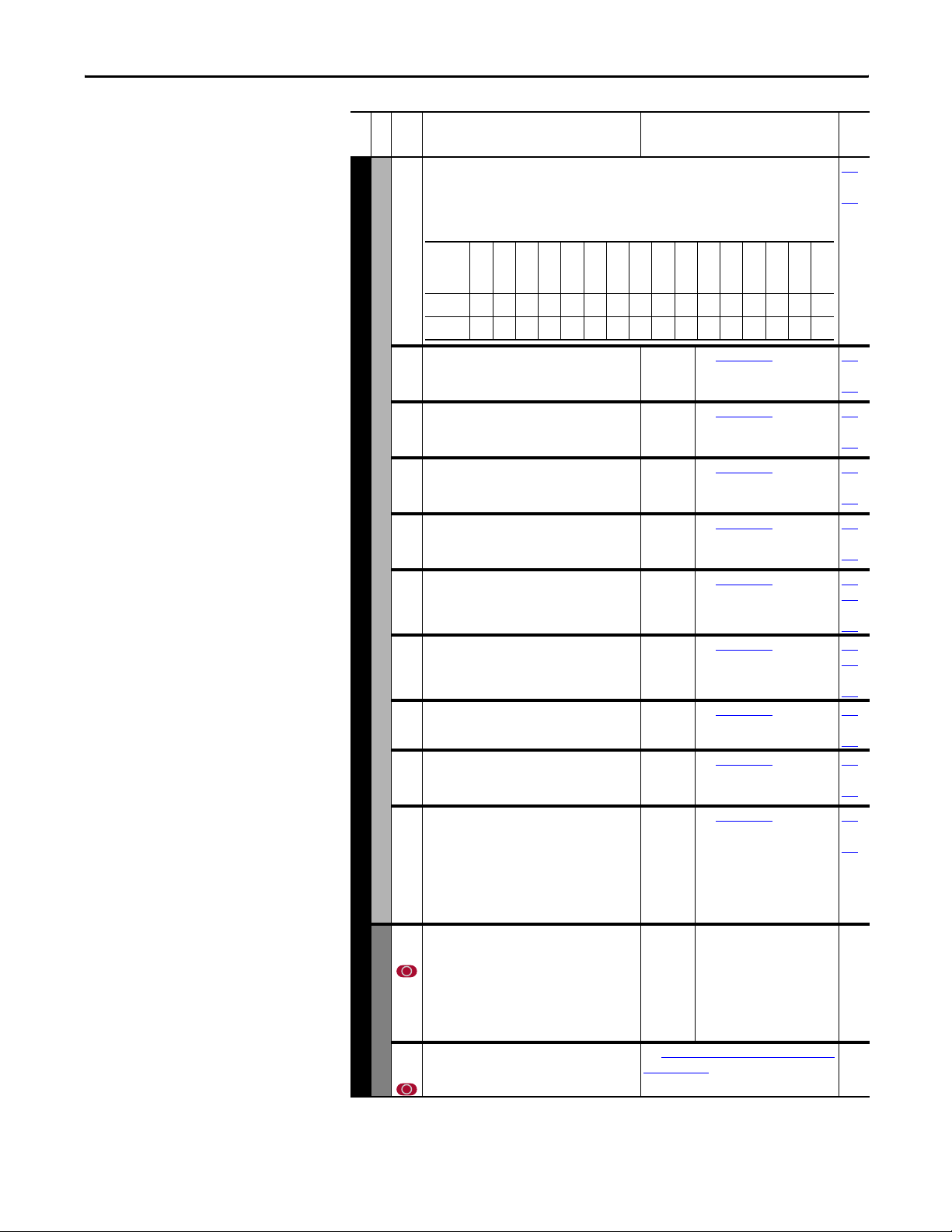
Programming and Parameters Chapter 2
File
Parameter Name & Description Values
Group
No.
288 [Stop Owner]
Adapters that are presently issuing a valid stop command.
1 = Issuing Command
0 = No Command
Defaultxxxxxxxxx0000000
Bit 1514131211109876543210
289 [Start Owner]
Adapters that are presently issuing a valid start
command.
290 [Jog Owner]
Adapters that are presently issuing a valid jog
command.
291 [Direction Owner]
Adapter that currently has exclusive control of
direction changes.
292 [Reference Owner]
Adapter that has the exclusive control of the
command frequency source selection.
Masks/Owners
293 [Accel Owner]
Adapter that has exclusive control of selecting
[Accel Time 1, 2].
294 [Decel Owner]
COMMUNICATION
Adapter that has exclusive control of selecting
[Decel Time 1, 2].
295 [Fault Clr Owner]
Adapter that is presently clearing a fault.
296 [MOP Owner]
Adapters that are currently issuing increases or
decreases in MOP command frequency.
297 [Local Owner]
Adapter that ha s requested exclusive control o f all
drive logic functions. If an adapter is in local
lockout, all other functions (except stop) on all
other adapters are locked out and non-functional.
Local control can only be obtained when the drive
is not running.
300
[Data In A1] - Link A Word 1
301
[Data In A2] - Link A Word 2
Parameter number whose value will be written
from a communications device data table.
Value will not be updated until drive is stopped.
Refer to your communications option manual for
Datalinks
datalink information.
302
[Data In B1] - Link B Word 1
303
[Data In B2] - Link B Word 2
Name
Related
Read Only 276
thru
285
Reserved
Reserved
Reserved
Reserved
Reserved
Reserved
Reserved
Reserved
Reserved
DPI Port 6
DPI Port 5
DPI Port 4
DPI Port 3
DPI Port 2
DPI Port 1
Digital In
See [Stop Owner]
. 276
thru
285
See [Stop Owner]
. 276
thru
285
See [Stop Owner]
. 276
thru
285
See [Stop Owner]
. 276
thru
285
See [Stop Owner]
. 140
276
thru
285
See [Stop Owner]
. 142
276
thru
285
See [Stop Owner]. 276
thru
285
See [Stop Owner]. 276
thru
285
See [Stop Owner]. 276
thru
285
Default:
Min/Max:
Units:
See [Data In A1] -
0 (0 = “Disabled”)
0/486
1
Link A Word 1 [Data In A2]
- Link A Word 2.
Rockwell Automation Publication 20C-PM001F-EN-P - March 2012 47
Page 48

Chapter 2 Programming and Parameters
File
Parameter Name & Description Values
Group
No.
304
[Data In C1] - Link C Word 1
305
[Data In C2] - Link C Word 2
306
[Data In D1] - Link D Word 1
307
[Data In D2] - Link D Word 2
310
[Data Out A1] - Link A Word 1
311
[Data Out A2] - Link A Word 2
Parameter number whose value will be written to
Datalinks
a communications device data table.
312
[Data Out B1] - Link B Word 1
313
[Data Out B2] - Link B Word 2
314
[Data Out C1] - Link C Word 1
315
[Data Out C2] - Link C Word 2
316
[Data Out D1] - Link D Word 1
317
[Data Out D2] - Link D Word 2
595 [Port Mask Ac t]
Bits 0…6 indicate status for DPI port communication. Bit 15
indicates when security software is controlling the parameter.
Note: Added for firmware revision 4.001
1 = Active
0 = Not Active
COMMUNICATIONS
See [Data In A1] - Link A Word 1 [Data In A2]
- Link A Word 2.
See [Data In A1] -
Link A Word 1 [Data In A2]
- Link A Word 2.
Default:
Min/Max:
Units:
See [Data Out A1] -
0 (0 = “Disabled”)
0/544
1
Link A Word 1 [Data Out
A2] - Link A Word 2.
See [Data Out A1] -
Link A Word 1 [Data Out
A2] - Link A Word 2.
See [Data Out A1] - Link A Word 1 [Data Out
A2] - Link A Word 2.
Read Only
Name
Security
Reserved
Reserved
Reserved
Reserved
Reserved
Reserved
Reserved
Reserved
DPI Port 6
DPI Port 5
DPI Port 4
DPI Port 3
DPI Port 2
DPI Port 1
Host
Default0xxxxxxxx0000000
Bit 1514131211109876543210
Related
596 [Write Mask Cfg]
Security
Enables/disables write access (parameters, links, etc.) for DPI ports. Changes to this parameter
only become effective when power is cycled, the drive is reset or bit 15 of parameter 597 [Write
Mask Act], transitions from “1” to “0.”
Note: Added for firmware revision 4.001.
1 = Write Permitted
0 = Read Only
Name
Reserved
Reserved
Reserved
Reserved
Reserved
Reserved
Reserved
Reserved
Reserved
DPI Port 6
DPI Port 5
DPI Port 4
Defaultxxxxxxxxx1111110
Bit 1514131211109876543210
DPI Port 3
DPI Port 2
DPI Port 1
Digital In
48 Rockwell Automation Publication 20C-PM001F-EN-P - March 2012
Page 49

Programming and Parameters Chapter 2
File
Parameter Name & Description Values
Group
No.
597 [Write Mask Act]
Status of write access for DPI ports. When bit 15 is set, network
security is controlling the write mask instead of parameter 596
[Write Mask Cfg].
Note: Added for firmware revision 4.001.
1 = Write Permitted
0 = Read Only
Default0xxxxxxxx0000000
Bit 1514131211109876543210
598 [Logic Mask Act]
Security
COMMUNICATIONS
Indicates status of the logic mask for DPI ports. When bit 15 is
set, network security is controlling the logic mask instead of
parameter 276 [Logic Mask].
Note: Added for firmware revision 4.001.
1 = Control Permitted
0 = Control Masked
Default0xxxxxxxx0000000
Bit 1514131211109876543210
Name
Name
Related
Read Only
Security
Reserved
Reserved
Reserved
Reserved
Reserved
Reserved
Reserved
Reserved
DPI Port 6
DPI Port 5
DPI Port 4
DPI Port 3
DPI Port 2
DPI Port 1
Host
Read Only
Security
Reserved
Reserved
Reserved
Reserved
Reserved
Reserved
Reserved
Reserved
DPI Port 6
DPI Port 5
DPI Port 4
DPI Port 3
DPI Port 2
DPI Port 1
Digital In
Inputs/Outputs File
File
Group
No.
320 [Anlg In Config]
Analog Inputs
INPUTS/OUTPUTS
Parameter Name & Description Values
Selects the mode for the analog inputs.
1 = Current
0 = Voltage
Name
Reserved
Reserved
Reserved
Reserved
Reserved
Reserved
Reserved
Reserved
Reserved
Reserved
Reserved
Reserved
Reserved
Reserved
An2 0=V 1=mA
Defaultxxxxxxxxxxxxxx00
Bit 1514131211109876543210
Related
322
325
323
326
An1 0=V 1=mA
Rockwell Automation Publication 20C-PM001F-EN-P - March 2012 49
Page 50

Chapter 2 Programming and Parameters
File
Parameter Name & Description Values
Group
No.
321 [Anlg In Sqr Root]
Enables/disables the square root function for each input.
1 = Enable
0 = Disable
Defaultxxxxxxxxxxxxxx00
Bit 1514131211109876543210
322
[Analog In1 Hi]
325
[Analog In2 Hi]
Sets the highest input value to the analog input x
scaling block.
[Anlg In Config], parameter 320 defines if this
input will be –/+10V or 0-20 mA.
Note: The Min. value was changed from 4.000mA
to 0.000mA for firmware revision 3.001.
Analog Inputs
323
[Analog In1 Lo]
326
[Analog In2 Lo]
Sets the lowest input value to the analog input x
scaling block.
[Anlg In Config], parameter 320 defines if this
input will be –/+10V or 0-20 mA.
INPUTS/OUTPUTS
Note: The Min. value was changed from 4.000mA
to 0.000mA for firmware revision 3.001.
324
[Analog In1 Loss]
327
[Analog In2 Loss]
Selects drive action when an analog signal loss is
detected. Signal loss is defined as an analog
signal less than 1V or 2mA. The signal loss event
ends and normal operation resumes when the
input signal level is greater than or equal to 1.5V
or 3mA.
340 [Anlg Out Config]
Selects the mode for the analog output s.
1 = Current
0 = Voltage
Name
Related
Reserved
Reserved
Reserved
Reserved
Reserved
Reserved
Reserved
Reserved
Reserved
Reserved
Reserved
Reserved
Reserved
Reserved
Analog In 2
Analog In 1
Default:
Min/Max:
10.000 Volt
10.000 Volt
0.000/20.000mA
091
092
–/+10.000V
0.000/10.000V
Units:
0.001 mA
0.001 Volt
Default:
Min/Max:
0.000 Volt
0.000 Volt
0.000/20.000mA
091
092
–/+10.000V
0.000/10.000V
Units:
0.001 mA
0.001 Volt
Default:
Options:
0
0
0
1
2
3
4
5
6
“Disabled”
“Disabled”
“Disabled”
“Fault”
“Hold Input”
“Set Input Lo”
“Set Input Hi”
“Goto Preset1”
“Hold OutFreq”
091
092
Analog Outputs
Name
Reserved
Reserved
Reserved
Reserved
Reserved
Reserved
Defaultxxxxxxxxxxxxxx00
Bit 1514131211109876543210
50 Rockwell Automation Publication 20C-PM001F-EN-P - March 2012
Reserved
Reserved
Reserved
Reserved
Reserved
Reserved
Reserved
Reserved
An2 0=V 1=mA
An1 0=V 1=mA
Page 51

Programming and Parameters Chapter 2
File
Parameter Name & Description Values
Group
No.
341 [Anlg Out Absolut]
Selects whether the signed value or absolute value of a parameter is used before being scaled to
drive the analog output.
1 = Absolute
0 = Signed
Defaultxxxxxxxxxxxxxx11
Bit 1514131211109876543210
342
[Analog Out1 Sel]
345
[Analog Out2 Sel]
Selects the source of the value that drives the
analog output.
Options
0
1
2
3
4
5
6
7
8
9
10
11
12
13…15
16
17…23
24
Analog Outputs
INPUTS/OUTPUTS
343
[Analog Out1 Hi]
346
[Analog Out2 Hi]
Sets the analog output value when the source
value is at maximum.
Note: The Min. value was changed from
4.000 mA…0.000 mA for firmware revision
3.001.
344
[Analog Out1 Lo]
347
[Analog Out2 Lo]
Sets the analog output value when the source
value is at minimum.
Note: The Min. value was changed from
4.000 mA…0.000 mA for firmware revision
3.001.
354
[Anlg Out1 Scale]
355
[Anlg Out2 Scale]
32
Sets the high value for the range of analog output
scale. Entering 0.0 will disabl e this scale and max
scale will be used. Example: If [Analog Outx Sel]
= “Commanded Freq,” a value of 150 = 150%
scale in place of the default 200%.
377
[Anlg1 Out Setpt]
378
[Anlg2 Out Setpt]
Sets the analog output value from a
communication device. Example: Set [Data In Ax]
to “377” (value from communication device).
Then set [Analog Outx Sel] to “Param Cntl.”
Name
Reserved
Reserved
“Output Freq”
“Command Freq”
“Output Amps”
“Torque Amps”
“Flux Amps”
“Output Power”
“Output Volts”
“DC Bus Volt”
“PI Reference”
“PI Feedback”
“PI Error”
“PI Output”
“%Motor OL”
“Reserved”
“Speed Ref”
“Reserved”
“Param Cntl”
Reserved
Reserved
Reserved
Reserved
[Analog Out x Lo] Value
–[Maximum Speed]
–[Maximum Speed]
0 Amps
–200% Rated
0 Amps
0 kW
0 Volts
0 Volts
–100%
–100%
–100%
–100%
0%
–
–[Maximum Speed]
–
Reserved
0 Hz
0 Hz/RPM
0 Amps
0 Amps
0 Amps
0 kW
0 Volts
0 Volts
0%
0%
0%
0%
0%
–
0 Hz
–
Reserved
Reserved
Reserved
Default:
Options:0–>
[Analog Out x Hi] ValuePar 341 = Signed Par 341 = Absolute
+[Maximum Speed]
+[Maximum Speed]
200% Rated
200% Rated
200% Rated
200% Rated
120% Rated Input Volts
200% Rated Input Volts
100%
100%
100%
100%
100%
–
+[Maximum Speed]
–
Default:
Min/Max:
20.000 mA, 10.000 Volts
0.000/20.000 mA
–/+10.000V
0.000/10.000V
Units:
0.001 mA
0.001 Volt
Default:
Min/Max:
0.000 mA, 0.000 Volts
0.000/20.000 mA
–/+10.000V
0.000/10.000V
Units:
0.001 mA
0.001 Volt
Default:
Min/Max:
Units:
Default:
Min/Max:
0.0
[Analog Ou tx Sel]
0.1
0.000 mA, 0.000 Volts
0.000/20.000 mA
–/+10.000V
Units:
0.001 mA
0.001 Volt
Reserved
Reserved
“Output Freq”
(See table below)
Related
Reserved
Reserved
Analog Out2
Analog Out1
001
002
003
004
005
007
006
012
135
136
137
138
220
340
342
345
340
342
345
342
345
342
345
Rockwell Automation Publication 20C-PM001F-EN-P - March 2012 51
Page 52

Chapter 2 Programming and Parameters
File
Parameter Name & Description Values
Group
No.
358 [20C-DG1 Remove]
Clears an F10 "System Fault" issued when the
drive has recognized that the 20C-DG1 option
board has been removed for service and has not
been re-installed. The drive is designed to
generate a non-resettable fault, F10 "System
Fault", if the option board is removed from the
drive's control. You must manually set this
parameter to 1"Remove" and then back to 0
"Ready" to clear and acknowledge the fault. Once
maintenance or service is completed and the 20CDG1 option card has been reinstalled, the drive
will recognize the option card on power-up.
Note: This parameter was added for firmware
revision 2.001. Please refer to the PowerFlex 700H
and 700S Drives Installation Manual (Frame
9…14), publication PFLEX-IN006
information on the 20C-DG1 option board.
359 [20C-DG1 Status]
Displays the status of the Gate Disable option board (20C-DG1) functions.
Bit 0 = Gate Disable active
Bit 1 = Thermistor input active
Bit 2 = Unexpected problem in Gate Disable circuitry / inputs
Bit 3 = No Gate Enable input on channel 1
Bit 4 = No Gate Enable input on channel 2
INPUTS/OUTPUTS
Bit 6 = The test pulse detected a problem in the thermistor input
Bit 5 = Thermistor short circuit detected
Digital Inputs
Bit 7 = +5V overvoltage detected on the 20C-DG1 option board
Bit 8 = +5V undervoltage detected on the 20C-DG1 option board
Bit 9 = The test pulse detected a problem in the Gate Disable inputs
Bit 10 = ASIC trip input ETR not set, even if the Gate Disable inputs are active
Bit 11 = +5V or REF voltage problem detected on the 20C-DG1 option board
Bit 12 = The 20C-DG1 option board has been removed
Bit 13 = The 20C-DG1 option board has an EEPROM error
Bit 14 = The 20C-DG1 option board has been found by identification software
Bit 15 = A system fault (unexpected hardware problem) has been generated and cannot be
cleared
Note: This parameter was added for firmware revision 2.001.
1 = True
0 = False
for more
Default:
Options:00
Related
“Ready”
359
“Ready”
“Remove”
1
358
Name
Unexp HW Pro
20C-DG1 ID O
20C-DG1 EEPR
20C-DG1 Remo
+5V Ref Prob
ASIC Trip In
Default0000000000000000
Bit 1514131211109876543210
52 Rockwell Automation Publication 20C-PM001F-EN-P - March 2012
Input Pulse
+5V Undervol
+5V Overvolt
Therm Pulse
Therm Shor t
NoEnable CH2
NoEnable CH1
Unexp In Pro
Therm Activ
Gate Disable
Page 53

Programming and Parameters Chapter 2
File
INPUTS/OUTPUTS
Parameter Name & Description Values
Group
No.
[Digital In1 Sel]
361
[Digital In2 Sel]
362
[Digital In3 Sel]
363
[Digital In4 Sel]
364
[Digital In5 Sel]
365
[Digital In6 Sel]
366
(9)
Selects the function for the digital inputs.
Notes: Options 36…42 are “Reserved”. Added
options 43 and 46 for firmware revision 3.001.
Added options 41, 42, 44 and 45 for firmware
revision 4.001. Added option 68 for firmware
revision 5.002.
(1)
Speed Select Inputs.
321Auto Reference Source
Reference A
0
0
0
0
0
0
1
1
1
1
To access Preset Speed 1, set [Speed Ref x Sel] to
“Preset Speed 1”.
Type 2 Alarms - Some digital input programming
may cause conflicts that will result in a Type 2
alarm. Example: [Digital In1 Sel] set to “5, Start” in
3-wire c ontrol and [Di gital In2 S el] set to 7 “R un”
in 2-wire.
Digital Inputs
Refer to Table 1 on page 64
resolving this type of conflict.
(2)
When [Digital Inx Sel] is set to option 2 “Clear
Faults” the Stop button cannot be used to clear a
fault condition.
(3)
Typical 3-Wire Inputs - Requires that only 3-wire
functions are chosen. Including 2-wire selections
will cause a type 2 alarm.
(4)
Typical 2-Wire Inputs - Requires that only 2-wire
functions are chosen. Including 3-wire selections
will cause a type 2 alarm. See Table 1 on page 64
for conflicts.
(5)
Auto/Manual - Refer to the Installation Manual for
details.
(6)
Opening an “Enable” input will cause the motor to
coast-to-stop, i gnoring any programmed Stop
modes.
(7)
A “Dig In ConflictB” alarm will occur if a “Start ” input is programmed without a “Stop” input.
(8)
Refer to the Sleep Wake Mode Attention statement on page 33.
(9)
A dedicated hardware enable input is available via a jumper selection. Refer to Installation Manual for
further information.
(10)
Refer to [Dyn UsrSet Sel] on page 37 for selection information.
(11)
Refer to Selected Option Definitions – [Analog Outx Sel], [Digital Inx Sel], [Digital Outx Sel] on page 55.
(12)
The function of this value is similar to 18 “Auto/Manual”, except the polarity is opposite.
Reference B
1
0
Preset Speed 2
0
1
Preset Speed 3
1
1
Preset Speed 4
0
0
Preset Speed 5
1
0
Preset Speed 6
0
1
Preset Speed 7
1
1
for information on
Default:
Default:
Default:
Default:
Default:
Default:
Options:
4
5
18
15
16
17
0
1
2
3
4
5
6
7
8
9
10
11
12
13
14
15
16
17
18
19
20
21
22
23
24
25
26
27
28
29
30-33
34
35
36-40
41
42
43
44
45
46
68
“Stop – CF”
“Start”
“Au to / Ma nu al”
“Speed Sel 1”
“Speed Sel 2”
“Speed Sel 3”
“Not Used”
(6)(8)
“Enable”
“Clear Fa ults”(CF)
“Aux Fault”
“Stop – CF”
“Start”
“Fwd/ Reverse”
“Run”
(8)
(3)(7)
(4)(8)
“Run Forward”
“Run Reverse”
(3)
“Jo g 1 ”
“Jo g For war d”
“Jo g R eve rs e”
“Stop Mode B”
“Bus Reg Md B”
“Speed Sel 1”
“Speed Sel 2”
“Speed Sel 3”
“Au to / Ma nu al”
“Local”
“Acc2 & Dec2”
“Accel 2”
“Decel 2”
“MOP Inc”
“MOP Dec”
“Excl Link”
(10)
(10)
(10)
“PI Enable”
“PI Hold”
“PI Reset”
“Pwr Loss Lvl”
Reserved
“Jo g 2 ”
“PI Invert”
“Reserved”
“UserSet Sel1”
“UserSet Sel2”
“Run Level”
(11)
“RunFwd Level”
“RunRev Level”
“Run w/Comm”
“Manual/Auto”
Related
(2)
(3)
(4)
(4)
100
(4)
(4)
156
(1)
(1)
(1)
162
(5)
096
141
143
195
194
124
(10)
(10)
(11)
(11)
(11)
(12)
Rockwell Automation Publication 20C-PM001F-EN-P - March 2012 53
Page 54

Chapter 2 Programming and Parameters
File
Parameter Name & Description Values
Group
No.
379 [Dig Out Setpt]
Sets the digital output value from a communication device.
Example:
Set [Data In B1] to “379.” The first three bits of this value will determine the setting of [Digital
Outx Sel] which should be set to value 30 “Param Cntl.”
1 = Output Energized
0 = Output De-energized
380
[Digital Out1 Sel]
384
[Digital Out2 Sel]
388
[Digital Out3 Sel]
Selects the drive status that will energize a (CRx)
output relay.
(1 )
Digital Outputs
INPUTS/OUTPUTS
(2)
(3)
Name
Reserved
Reserved
Reserved
Reserved
Reserved
Reserved
Reserved
Reserved
Reserved
Reserved
Reserved
Reserved
Reserved
Net DigOut3
Net DigOut2
Net DigOut1
Defaultxxxxxxxxxxxxx000
Bit 1514131211109876543210
Default:
Options:
Any relay programmed as Fault or Alarm will
energize (pick up) when power is applied to drive
and deenergize (drop out) when a fault or alarm
exists. Relays selected for other functions will
energize only when that condition exists and will
deenergize when condition is removed.
Activation level is defined in [Dig Outx Level] below.
Refer to Option Definitions on page 55.
1
4
4
1
2
3
4
5
6
7
8
9
10
11
12
13
14
15
16
17
18
19
20
21-26
27
28
29
30
“Fault”
“Run”
“Run”
(1)
“Fault”
(1)
“Al a r m”
“Ready”
“Run”
“Forward Run”
“Reverse Run”
“Auto Restart”
“Powerup Run”
“At Sp ee d”
(2)
“At Freq ”
“At Cu rre nt ”
“At Tor que”
“At Temp”
“At Bu s Vo lt s”
“At PI Error”
(2)
(2)
(2)
“DC Braking”
“Curr Limit”
“Reserved”
“Motor Overld”
“Power Loss”
“Input 1-6 Link”
“PI Enable”
“PI Hold”
“Reserved”
“Param Cntl”
(3)
(2)
Related
380
384
388
381
385
389
382
386
390
383
002
001
003
004
218
012
137
157
147
053
048
184
54 Rockwell Automation Publication 20C-PM001F-EN-P - March 2012
Page 55

Programming and Parameters Chapter 2
File
INPUTS/OUTPUTS
Parameter Name & Description Values
Group
No.
Selected Option Definitions – [Analog Outx Sel], [Digital Inx Sel], [Digital Outx Sel]
Option Description Related
At Speed Relay changes state when drive has reached commanded speed. 380 384 388
Excl Link Links digital input to a digital output if the output is set to “Input 1…6
Link.” This does not need to be selected in the Vector option.
Input 1-6 Link When Digital Output 1 is set to one of these (i.e. Input 3 Link) in
MOP Dec Decrements speed reference as long as input is closed. 361…366
MOP Inc Incre ments speed re ference as lon g as input is closed. 361…366
Param Cntl (A.O.) Parameter controlled analog output allows PLC to control analog
Param Cntl (D.O.) Parameter controlled digital output allows PLC to control digital outputs
PI Reference Reference for PI block (see Process PI on page 93). 342 345
Run Level
RunFwd Level
RunRev Level
Run w/Comm Allows the Comms start bit to operate like a run with the run input on
Digital Outputs
[Dig Out1 Level]
381
[Dig Out2 Level]
385
[Dig Out3 Level]
389
Sets the relay activation level for options 10…15
in [Digital Outx Sel]. Units are assumed to match
the above selection (i.e. “At Freq” = Hz, “At
Tor que ” = Am ps ).
[Dig Out1 OnTime]
382
[Dig Out2 OnTime]
386
[Dig Out3 OnTime]
390
Sets the “ON Delay” time for the digital outputs.
This is the time between the occurrence of a
condition and activation of the relay.
[Dig Out1 OffTime]
383
[Dig Out2 OffTime]
387
[Dig Out3 OffTime]
391
Sets the “OFF Delay” time for the digital outputs.
This is the time between the disappearance of a
condition and de-activation of the relay.
conjunction with Digital Input 3 set to “Excl Link,” the Digital Input 3
state (on/off) is echoed in the Digital Output 1.
outputs through data links. Set in [Anlgx Out Setpt], par. 377…378.
through data links. Set in [Dig Out Setpt], parameter 379.
Provides a run level input. A run level input doe s not require a transition
for enable or fault, but does require a transition for a stop.
the terminal block. Ownership rules apply.
Default:
Min/Max:
Units:
Default:
Min/Max:
Units:
Default:
Min/Max:
Units:
0.0
0.0
0.0
0.0/1500.0
0.1
0.00 Secs
0.00 Secs
0.00 Secs
0.00/163.00 Secs
0.01 Secs
0.00 Secs
0.00 Secs
0.00 Secs
0.00/163.00 Secs
0.01 Secs
Related
361…366
380 384 388
342 345
380 384 388
361…366
361…366
380
384
388
380
384
388
380
384
388
Rockwell Automation Publication 20C-PM001F-EN-P - March 2012 55
Page 56

Chapter 2 Programming and Parameters
Parameter List by Name
Parameter Name Number Group Page
20C-DG1 Remove 358 Digital Inputs 2-52
20C-DG1 Status 359 Digital Inputs 2-52
Accel Mask 281 Masks/Owners 2-46
Accel Owner 293 Masks/Owners 2-47
Accel Time X 140, 141 Ramp Rates 2-30
Alarm Clear 261 Alarms 2-44
Alarm Config 1 259 Al arms 2-44
Alarm X @ Fault 229, 230 Diagnostics 2-41
Alarm X Code 262-269 Alarms 2-44
Analog In X Hi 322, 325 Analog Inputs 2-50
Analog In X Lo 323, 326 Analog Inputs 2-50
Analog In X Loss 324, 327 Analog Inputs 2-50
Analog In1 Value 016 Metering 2-20
Analog In2 Value 017 Metering 2-20
Analog OutX Hi 343, 346 Analog Outputs 2-51
Analog OutX Lo 344, 347 Analog Outputs 2-51
Analog OutX Sel 342, 345 Analog Outputs 2-51
Anlg In Config 320 Analog Inputs 2-49
Anlg In Sqr Root 321 Analog Inputs 2-50
Anlg Out Absolut 341 Analog Outputs 2-51
Anlg Out Config 340 Analog Outputs 2-50
Anlg OutX Scale 354, 355 Analog Outputs 2-51
Anlg OutX Setpt 377, 378 Analog Outputs 2-51
Auto Rstrt De lay 17 5 Restart Mod es 2-32
Auto Rstrt Tries 174 Restart Modes 2-32
Autotune 061 Torq Attributes 2-23
Break Frequency 072 Volts per Hertz 2-23
Break Voltage 071 Volts per Hertz 2-23
Bus Reg Kd 165 Stop/Brake Modes 2-32
Bus Reg Ki 160 Stop/Brake Modes 2-31
Bus Reg Kp 164 Stop/Brake Modes 2-32
Bus Reg Mode X 161, 162 Stop/Brake Modes 2-31
Commanded Speed 002 Metering 2-20
Command ed Torque 024 Metering 2-21
Compensation 056 Torq Attributes 2-22
Control SW Ver 029 D rive Data 2-21
Current Lmt Gain 149 Load Limits 2-30
Current Lmt Sel 147 Load Limits 2-30
Current Lmt Val 148 Load Limits 2-30
Data In XX 300-307 Datalinks 2-47
Data Out XX 310-317 Datalinks 2-48
DB Resistor Type 163 Stop/Brake Modes 2-31
DB While Stopped 145 Ramp Rates 2-30
DC Brake Level 158 Stop/Brake Modes 2-31
DC Brake Time 159 Stop/Brake Modes 2-31
DC Brk Lvl Sel 157 Stop/Brake Modes 2-31
DC Bus Memory 013 Metering 2-20
DC Bus Voltage 012 Metering 2-20
Decel Mask 282 Masks/Owners 2-46
Decel Owner 294 Masks/Owners 2-47
Decel Time X 142, 143 Ramp Rates 2-30
Dig In Status 21 6 Diagnostics 2-40
Dig Out Setpt 379 Digital Outputs 2-54
Dig Out Status 217 Diagnostics 2-40
Dig OutX Level 381, 385,
Dig OutX OffTime 383, 387,
Dig OutX OnTime 382, 386,
Digital InX Sel 361-366 Digital Inputs 2-53
Digital OutX Sel 380, 384,
Direction Mask 279 Masks/Owners 2-46
Direction Mode 190 Direction Config 2-35
Direction Owner 291 M asks/Owners 2-47
DPI Port Sel 274 Comm Control 2-46
DPI Port Value 275 Comm Control 2-46
Drive Alarm X 211, 212 Diagnostics 2-38
Drive Checksum 203 Drive Memory 2-36
Drive Logic Rslt 271 Comm Control 2-45
Digital Outputs 2-55
389
Digital Outputs 2-55
391
Digital Outputs 2-55
390
Digital Outputs 2-54
388
Parameter Name Number Group Page
Drive OL Mode 150 Load Limits 2-30
Drive Ramp Rslt 273 Comm Control 2-45
Drive Ref Rslt 272 Comm Control 2-45
Drive Status X 209, 210 Diagnostic s 2-38
Drive Temp 218 Diagnostics 2-40
Droop RPM @ FLA 152 Load Limits 2-30
Dyn UserSet Actv 206 Drive Memory 2-37
Dyn UserSet Cnfg 204 Drive Memory 2-37
Dyn UserSet Sel 205 Drive Memory 2-37
Elapsed MWh 009 Metering 2-20
Elapsed Run Time 010 Metering 2-20
Fan Control 465 Stop/Brake Modes 2-32
Fault 1 Code 2 43 Fa ults 2-43
Fault 1 Subcode 543 Faults 2-43
Fault 1 Time 2 44 Fa ults 2-43
Fault 2 Code 2 45 Fa ults 2-43
Fault 2 Subcode 545 Faults 2-43
Fault 2 Time 2 46 Fa ults 2-43
Fault 3 Code 2 47 Fa ults 2-43
Fault 3 Subcode 547 Faults 2-43
Fault 3 Time 2 48 Fa ults 2-43
Fault 4 Code 2 49 Fa ults 2-43
Fault 4 Subcode 549 Faults 2-43
Fault 4 Time 2 50 Fa ults 2-43
Fault 5 Code 2 51 Fa ults 2-43
Fault 5 Subcode 551 Faults 2-43
Fault 5 Time 2 52 Fa ults 2-43
Fault 6 Code 2 53 Fa ults 2-43
Fault 6 Subcode 553 Faults 2-43
Fault 6 Time 2 54 Fa ults 2-43
Fault 7 Code 2 55 Fa ults 2-43
Fault 7 Subcode 555 Faults 2-43
Fault 7 Time 2 56 Fa ults 2-43
Fault 8 Code 2 57 Fa ults 2-43
Fault 8 Subcode 557 Faults 2-43
Fault 8 Time 2 58 Fa ults 2-43
Fault Amps 225 Diagnostics 2-40
Fault Bus Volts 226 Diagnostics 2-40
Fault Clear 240 Faults 2-42
Fault Clear Mode 241 Faults 2-42
Fault Clr Mask 283 M asks/Owners 2-46
Fault Clr Owner 295 Masks/Owners 2-47
Fault Config 1 238 Faults 2-42
Fault Frequency 224 Diagnostics 2-40
Feedback Select 080 Sp d Mode/Limits 2-24
Flux Current 005 Metering 2-20
Flux Current Ref 063 Torq Attributes 2-23
Flux Up Mode 057 Torq Attributes 2-23
Flux Up Time 058 Torq Attributes 2-23
Flying Start En 169 Restart Mo des 2-32
IR Voltage Drop 062 Torq Attributes 2-23
Jog Mask 278 Masks/Owners 2-46
Jog Owner 290 Masks/Owners 2-47
Jog Speed 1 100 Discrete Speeds 2-26
Jog Speed 2 108 Discrete Speeds 2-26
Language 201 Drive Memory 2-36
Last Stop Source 215 Diagnostics 2-40
Load Frm Usr Set 198 D rive Memory 2-36
Local Mask 285 Masks/Owners 2-46
Local Owner 297 Masks/Owners 2-47
Logic Mask 276 Masks/Owners 2-46
Logic Mask Act 598 S ecurity 2-49
Man Ref Preload 193 HIM Ref Config 2-35
Maximum Freq 055 Torq Attributes 2-22
Maximum Speed 082 Spd Mode/Limits 2-24
Minimum Speed 081 Spd Mode/Limits 2-24
MOP Mask 284 Masks/Owners 2-46
MOP Owner 296 Masks/Owners 2-47
MOP Rate 195 MOP Config 2-35
MOP Reference 011 Metering 2-20
Motor Cntl Sel 053 Torq Attributes 2-22
56 Rockwell Automation Publication 20C-PM001F-EN-P - March 2012
Page 57

Programming and Parameters Chapter 2
Parameter Name Number Group Page
Motor NP FLA 042 Motor Data 2-21
Motor NP Hert z 043 Mo tor Data 2-21
Motor NP Power 0 45 Motor Data 2-21
Motor NP RPM 044 Motor Data 2-21
Motor NP Volts 041 Motor Data 2-21
Motor OL Count 220 Diagnostics 2-40
Motor OL Factor 048 Motor D ata 2-22
Motor OL Hert z 047 Motor Data 2-22
Motor OL Mode 050 Motor Data 2-22
Motor Poles 049 Motor Data 2-22
Motor Type 0 40 Motor Data 2-21
Mtr NP Pwr Units 046 Motor Data 2-22
Output Current 003 Metering 2-20
Output Freq 001 Metering 2-20
Output Power 007 M etering 2-20
Output Powr Fctr 008 Metering 2-20
Output Voltage 006 Metering 2-20
Overspeed Limit 083 Spd Mode/Limits 2-24
Param Access Lvl 196 D rive Memory 2-35
PI Configuration 124 Process PI 2-28
PI Control 125 Process PI 2-28
PI Error Meter 1 37 Process PI 2-29
PI Fdback Meter 136 Process PI 2-29
PI Feedback Hi 462 Process PI 2-29
PI Feedback Lo 463 Process PI 2-29
PI Feedback Sel 128 Process PI 2-28
PI Integral Time 129 Process PI 2-28
PI Lower Limit 131 Process PI 2-28
PI Output Meter 138 Process PI 2-29
PI Preload 133 Process PI 2-29
PI Prop Gain 130 Process PI 2-28
PI Ref Meter 135 Process PI 2-29
PI Reference Hi 460 Process PI 2-29
PI Reference Lo 46 1 Process PI 2-29
PI Reference Sel 126 Process PI 2-28
PI Setpoint 127 Process PI 2-28
PI Status 134 Process PI 2-29
PI Output Gain 4 64 Process PI 2-29
PI Upper Limit 132 Process PI 2-28
Port Mask Act 595 Security 2-48
Power Loss Vo lts 186 Power Loss 2-34
Power Loss Mode 184 Power Loss 2-34
Power Loss Time 185 Power Loss 2-34
Power Up Marker 242 Faults 2-42
Powerup Delay 167 Restar t Modes 2-32
Preset Speed X 101-107 Discrete Speeds 2-26
PWM Frequency 151 Load Limits 2-30
Ramped Speed 022 Metering 2-20
Rated Amps 028 Drive Data 2-21
Rated kW 026 Drive Data 2-21
Rated Volts 027 Drive Data 2-21
Reference Mask 280 Masks/Owners 2-46
Reference Owner 292 Masks/Owners 2-47
Reset Meters 2 00 Drive Memory 2-36
Reset To Defalts 197 Drive Memory 2-36
Rev Speed Limit 454 Speed Regulator 2-25
S Curve % 146 Ramp Rates 2-30
Save HIM Ref 192 HIM Ref Config 2-35
Save MOP Ref 194 MOP Config 2-35
Save To User Set 199 Drive Memory 2-36
Shear Pin Time 189 Power Loss 2-34
Skip Freq Band 087 Spd Mode/Limits 2-24
Skip Frequency X 084-086 Spd Mode/Limits 2-24
Sleep Level 182 Restart Modes 2-33
Sleep Time 183 Restart Modes 2-33
Sleep Wake Mode 178 Restart Modes 2-33
Sleep Wake Ref 179 Restart Modes 2-33
Slip RPM @ FLA 121 Slip Comp 2-27
Slip RPM Meter 123 Slip Comp 2-27
Speed Feedback 025 Metering 2-21
Speed Ref Source 213 Diagnostics 2-39
Parameter Name Number Group Page
Speed Ref X Hi 091, 094 Speed Re ference 2-25
Speed Ref X Lo 092, 095 Speed Reference 2-25
Speed Ref X Sel 090, 093 Speed Reference 2-25
Speed Reference 023 Metering 2-21
Speed Units 079 Spd Mode/Limits 2-24
Speed/Torque Mod 088 Spd Mode/Limits 2-25
Start At PowerUp 168 Restart Modes 2-32
Start Inhibits 214 Diagnostics 2-39
Start Mask 277 Masks/Owners 2-46
Start Owner 289 Masks/Owners 2-47
Start/Acc Boost 069 Volts per Hertz 2-23
Status X @ Fault 227, 228 Diagnostics 2-41
Stop Owner 288 Masks/Owners 2-47
Stop/Brk Mode X 155, 156 Stop/Brake Modes 2-31
SV Boost Filter 059 Torq Attributes 2-23
TB Man Ref Hi 097 Speed Reference 2-26
TB Man Ref Lo 098 Speed Reference 2-26
TB Man Ref Sel 096 Speed Reference 2-26
Testpoint 1 Data 235 Diagnostics 2-42
Testpoint 2 Data 237 Diagnostics 2-42
Testpoint 1 Sel 234 Diagnostics 2-42
Testpoint 2 Sel 236 Diagnostics 2-42
Torque Current 004 Metering 2-20
Trim % Setpoint 116 Sp eed Trim 2-26
Trim Hi 119 Speed Trim 2-27
Tri m In S ele ct 1 17 Spe ed Tr im 2-27
Tri m Lo 12 0 S pee d Tri m 2-27
Tri m Out Sel ect 11 8 S pee d Tri m 2-27
Wake Level 180 Restart Modes 2-33
Wake Time 181 Restart Modes 2-33
Write Mask Act 597 S ecurity 2-49
Write Mask Cfg 596 Securit y 2-48
Voltage Class 202 Drive Memor y 2-36
Rockwell Automation Publication 20C-PM001F-EN-P - March 2012 57
Page 58

Chapter 2 Programming and Parameters
Parameter List by Number
Number Parameter Name Group Page
001 Output Freq Metering 2-20
002 Commanded Speed Metering 2-20
003 Output Current Metering 2-20
004 Torque Current Metering 2-20
005 Flux Current Metering 2-20
006 Output Voltage Metering 2-20
007 Output Power Metering 2-20
008 Output Powr Fctr Metering 2-20
009 Elapsed MWh Metering 2-20
010 Elapsed Run Time Metering 2-20
011 MOP Reference Metering 2-20
012 DC Bus Voltage Metering 2-20
013 DC Bus Memory Metering 2-20
016 Analog In1 Value Metering 2-20
017 Analog In2 Value Metering 2-20
022 Ramped Speed Metering 2-20
023 Speed Reference Metering 2-21
024 Commanded Torque Metering 2-21
025 Speed Feedback Metering 2-21
026 Rated kW Drive Data 2-21
027 Rated Volts Drive Data 2-21
028 Rated Amps Drive Data 2-21
029 Control SW Ver Drive Data 2-21
040 Motor Type Motor Data 2-21
041 Motor NP Volts Motor Data 2-21
042 Motor NP FLA Motor Data 2-21
043 Motor NP Hertz Motor Data 2-21
044 Motor NP RPM Motor Data 2-21
045 Motor NP Power Motor Data 2-21
046 Mtr NP Pwr Units Motor Data 2-22
047 Motor OL Hertz Motor Data 2-22
048 Motor OL Factor Motor Data 2-22
049 Motor Poles Motor Data 2-22
050 Motor OL Mode Motor Data 2-22
053 Motor Cntl Sel Torq Attributes 2-22
055 Maximum Freq Torq Attributes 2-22
056 Compensation Torq Attributes 2-22
057 Flux Up Mode Torq Attributes 2-23
058 Flux Up Time Torq Attributes 2-23
059 SV Boost Filter Torq Attributes 2-23
061 Autotune Torq Attributes 2-23
062 IR Voltage Drop Torq Attributes 2-23
063 Flux Current Ref Torq Attributes 2-23
069 Start/Acc Boost Volts per Hertz 2-23
071 Break Voltage Volts per Hertz 2-23
072 Break Frequency Volts per Hertz 2-23
079 Speed Units Spd Mode/Limits 2-24
080 Feedback Select Spd Mode/Limits 2-24
081 Minimum Speed Spd Mode/Limits 2-24
082 Maximum Speed Spd Mode/Limits 2-24
083 Overspeed Limit Spd Mode/Limits 2-24
084-086 Skip Frequency X Spd Mode/Limits 2-24
087 Skip Freq Band Spd Mode/Limits 2-24
088 Speed/Torque Mod Spd Mode/Limits 2-25
090, 093 Speed Ref X Sel Speed Reference 2-25
091, 094 Speed Ref X Hi Speed Reference 2-25
092, 095 Speed Ref X Lo Speed Reference 2-25
096 TB Man Ref Sel Speed Reference 2-26
097 TB Man Ref Hi Speed Reference 2-26
098 TB Man Ref Lo Speed Reference 2-26
100 Jog Speed 1 Discrete Speeds 2-26
101-107 Preset Speed X Discrete Speeds 2-26
108 Jog Speed 2 Discrete Speeds 2-26
116 Trim % Setpoint Speed Trim 2-26
117 Trim In Select Speed Trim 2-27
118 Trim Out Select Speed Trim 2-27
119 Trim Hi Speed Trim 2-27
120 Trim Lo Speed Trim 2-27
121 Slip RPM @ FLA Slip Comp 2-27
123 Slip RPM Meter Slip Comp 2-27
Number Parameter Name Group Page
124 P I Configurati on Process PI 2-28
125 P I Control Process PI 2-28
126 P I Reference S el Process PI 2-28
127 PI Setpoint Process PI 2-28
128 PI Feedback Sel Process PI 2-28
129 PI Integral Time Process PI 2-28
130 PI Pro p Gain Process PI 2- 28
131 PI Lower Limit Process PI 2-28
132 PI Upper Limit Process PI 2-28
133 PI Preload Process PI 2-29
134 PI Status Process PI 2-29
135 PI Ref Meter Process PI 2-29
136 PI Fdback Meter Process PI 2-29
137 P I Error Meter Process PI 2- 29
138 PI O utput Meter Pro cess PI 2-29
140, 141 Accel Time X Ramp Rates 2-30
142, 143 Decel Time X Ramp Rates 2-30
145 DB While Stopped Ramp Rates 2-30
146 S Curve % Ramp Rates 2-30
147 Current Lmt Sel Load Limits 2-30
148 Current Lmt Val Load Limits 2-30
149 Current Lmt Gai n Load Limits 2-30
150 Drive OL Mode Load Limits 2-30
151 PWM Frequency Load Limits 2-30
152 Droop RPM @ FLA Load Limits 2-30
155, 156 Stop/Brk Mode X Stop/Brake Modes 2-31
157 DC Brk Lvl Sel Stop/Brake Modes 2-31
158 DC Brake Level Stop/Brake Modes 2-31
159 D C Brake Time Stop/ Brake Modes 2-31
160 Bus Reg Ki Stop/Brake Modes 2-31
161, 162 Bus Reg Mode X Stop/Brake Modes 2-31
163 DB Resistor Type Stop/Brake Modes 2-31
164 Bus Reg Kp Stop/Brake Modes 2-32
165 Bus Reg Kd Stop/Brake Modes 2-32
167 Powerup Delay Restart Modes 2-32
168 Start At PowerUp Restart Modes 2-32
169 Flying Start En Restart M odes 2-32
174 Auto Rstrt Tries Restart Modes 2-32
175 Auto Rstrt Delay Restart Modes 2-32
178 Sleep Wake Mode Restar t Modes 2-33
179 Sleep Wake Ref Restart Modes 2-33
180 Wake Level Restart Modes 2-33
181 Wake Time Restart Modes 2-33
182 Sleep Level Restart Modes 2-33
183 Sleep Time Restar t Modes 2-33
184 Power Loss M ode Power Lo ss 2-34
185 Power Loss Ti me Powe r Loss 2-34
186 Power Loss Volt s Power Loss 2-34
189 Shear Pin Time Power Loss 2-34
190 Direction Mode Direction Config 2- 35
192 Save HIM Ref HIM Ref Config 2-35
193 Man Ref Preload HIM Ref Config 2-35
194 Save MOP Ref MOP Config 2-35
195 MOP Rate MOP Config 2-35
196 Param Access Lvl Drive Memory 2-35
197 Reset To Defalts Drive Memory 2- 36
198 Load Frm Usr Set Drive Memory 2-36
199 Save To User Set Drive Memory 2-36
200 Reset Meters Drive Memor y 2-36
201 Language Drive Memory 2-36
202 Voltage Class Drive Memory 2-36
203 Drive Checksum Drive Memory 2-36
204 Dyn UserSet Cnfg Drive Memory 2-37
205 Dyn UserSet Sel Drive Memory 2-37
206 Dyn UserSet Actv Drive Memory 2-37
209, 210 Drive Status X Diagnostics 2-38
211, 212 Drive Alarm X Diagnostics 2-38
213 Speed Ref Source Diagnostics 2-39
214 Star t Inhibits Diagno stics 2-39
215 Last Stop Source Diagnostics 2-40
216 Dig In Status Diagnostics 2-40
58 Rockwell Automation Publication 20C-PM001F-EN-P - March 2012
Page 59

Programming and Parameters Chapter 2
Number Parameter Name Group Page
217 Dig Out Status Diagnostics 2-40
218 Drive Temp Diagnostics 2-40
220 Motor OL Count Diagnosti cs 2-40
224 Fault Frequency Diagnostics 2-40
225 Fault Amps Diagnostics 2-40
226 Fault Bus Volts Diagnostics 2-40
227, 228 Status X @ Fault Diagnostics 2-41
229, 230 Alarm X @ Fault Diagnostics 2-41
234, 236 Testpoint x Sel Diagnostics 2-42
235, 237 Testpoint x Data Diagnostics 2-42
238 Fault Config 1 Faults 2-42
240 Fault Clear Faults 2-42
241 Fault Clear Mode Faults 2-42
242 Power Up Marker Faults 2-42
243 Fault 1 Code Faults 2-43
244 Fault 1 Time Faults 2-43
245 Fault 2 Code Faults 2-43
246 Fault 2 Time Faults 2-43
247 Fault 3 Code Faults 2-43
248 Fault 3 Time Faults 2-43
249 Fault 4 Code Faults 2-43
250 Fault 4 Time Faults 2-43
251 Fault 5 Code Faults 2-43
252 Fault 5 Time Faults 2-43
253 Fault 6 Code Faults 2-43
254 Fault 6 Time Faults 2-43
255 Fault 7 Code Faults 2-43
256 Fault 7 Time Faults 2-43
257 Fault 8 Code Faults 2-43
258 Fault 8 Time Faults 2-43
259 Alarm Config 1 Alarms 2-44
261 Alarm Clear Alarms 2-44
262 Alarm 1 Code Alarms 2-44
263 Alarm 2 Code Alarms 2-44
264 Alarm 3 Code Alarms 2-44
265 Alarm 4 Code Alarms 2-44
266 Alarm 5 Code Alarms 2-44
267 Alarm 6 Code Alarms 2-44
268 Alarm 7 Code Alarms 2-44
268 Alarm 8 Code Alarms 2-44
271 D rive Logic Rsl t Comm Co ntrol 2-45
272 D rive Ref Rsl t Com m Control 2-45
273 Drive Ramp Rslt Comm Control 2-45
274 D PI Port Sel Comm Control 2-46
275 D PI Port Value Comm Cont rol 2-46
276 Logic Mask Masks/Owners 2-46
277 Start Mask Masks/Owners 2-46
278 Jog Mask Masks/Owners 2-46
279 Direction Mask Masks/Owners 2-46
280 Reference Mask Masks/Owners 2-46
281 Accel Mask Masks/Ow ners 2-46
282 Decel Mask Masks/Owners 2-46
283 Fault Clr Mask Masks/Owners 2-46
284 MOP Mask Masks/Owners 2-46
285 Local Mask Masks/Owners 2-46
288 Stop Owner Masks/Owners 2-47
289 Start Owner Masks/Owners 2-47
290 Jog Owner Masks/Owners 2-47
291 Direction Owner Masks/Owners 2-47
292 Reference Owner Masks/Owners 2-47
293 Accel Owner Masks/Owners 2-47
294 Decel Owner Masks/Owners 2-47
295 Fault Clr Owner Masks/Owners 2-47
296 MOP Owner Masks/Owners 2-47
297 Local Owner Masks/Owners 2-47
300-307 Data In XX Datalinks 2-47
310-317 Data Out XX Datalinks 2-48
320 Anlg In Config Analog Inputs 2-49
321 Anlg In Sqr Root Analog Inputs 2-50
322, 325 Analog In X Hi Analog Inputs 2-50
323, 326 Analog In X Lo Analog Inputs 2-50
Number Parameter Name Group Page
324, 327 Analog In X Loss Analog Inputs 2-50
340 Anlg Out Config Analog Outputs 2-50
341 Anlg Out Absolut Analog Outputs 2-51
342, 345 Analog OutX Sel Analog Outputs 2-51
343, 346 Analog OutX Hi Analog Outputs 2-51
344, 347 Analog OutX Lo Analog Outputs 2-51
354, 355 Anlg OutX Scale Analog Outputs 2-51
358 20C-DG1 Remove Digital Inputs 2-52
359 20C-DG1 Status Digital Inputs 2-52
361-366 Digital InX Sel Digital Inputs 2-53
377, 378 Anlg OutX Setpt Analog Outputs 2-51
379 Dig Out Setpt Digital Outputs 2-54
380, 384,
Digital OutX Sel Dig ital Outputs 2-54
388
381, 385,
Dig OutX Level Digital Outputs 2-55
389
382, 386,
Dig OutX OnTime Digital Outputs 2-55
390
383, 387,
Dig OutX OffTime Digital Outputs 2-55
391
454 Rev Speed Limit Speed Regulator 2-25
460 PI Reference Hi Process PI 2-29
461 PI Reference Lo Process PI 2-29
462 PI Feedback Hi Process PI 2-29
463 PI Feedback Lo Process PI 2-29
464 PI Output Gain Process PI 2-29
465 Fan Control Stop/Brake Modes 2-32
543 Fault 1 Subcode Faults 2-43
545 Fault 2 Subcode Faults 2-43
547 Fault 3 Subcode Faults 2-43
549 Fault 4 Subcode Faults 2-43
551 Fault 5 Subcode Faults 2-43
553 Fault 6 Subcode Faults 2-43
555 Fault 7 Subcode Faults 2-43
557 Fault 8 Subcode Faults 2-43
595 Port Mask Act Securit y 2-48
596 Write Mask Cfg Security 2-48
597 Write Mask Act Security 2- 49
598 Logic Mask Act Security 2-49
Rockwell Automation Publication 20C-PM001F-EN-P - March 2012 59
Page 60

Chapter 2 Programming and Parameters
Notes:
60 Rockwell Automation Publication 20C-PM001F-EN-P - March 2012
Page 61

Chapter 3
Troubleshooting
This chapter provides information to guide you in troubleshooting the
PowerFlex 700H drive. Included is a listing and description of drive faults and
alarms (with possible solutions, when applicable).
For Information on… See page…
Drive Status 62
Faults and Alarms 63
Manually Clear Faults 63
Fault and Alarm Descriptions 64
Fault Subcodes 71
Clear Alarms 77
Common Drive Symptoms and Corrective Actions 77
Technical Support Options 79
Rockwell Automation Publication 20C-PM001F-EN-P - March 2012 61
Page 62

Chapter 3 Troubleshooting
Drive Status
The condition or state of your drive is constantly monitored. Any changes will be
indicated through the LEDs and/or the HIM (if present).
Front Panel LED Indications
1
2
# Name Color State Description
1 PWR (Power) Green Steady Illuminates when power is applied to the drive.
2 PORT
(1) Refer to the appropriate Communication Option User Manual for details.
MOD
NET A
NET B
(1)
(1)
(1)
(1)
Green – Status of DPI port internal communications (if present).
Yellow – Status of communications module (when installed).
Red – Status of network (if connected).
Red – Status of secondary network (if connected).
HIM Indications
The LCD HIM also provides visual notification of a fault or alarm condition.
Condition Display
Drive is indicating a fault.
The LCD HIM immediately repor ts the fault condition by
displaying the following.
• “Faulted” appears in the status line
• Fa ult n umber
• Fa ult n ame
• Time that has passed since fault occurred
Press Esc to regain HIM control.
Drive is indicating an alarm.
The LCD HIM immediately reports the alarm condition by
displaying the following.
• Alarm name (Type 2 alarms only)
• Alarm bell graphic
62 Rockwell Automation Publication 20C-PM001F-EN-P - March 2012
F-> Faulted Auto
Hz
0.0
— Fault — F5
Main Menu:
OverVoltage
Diagnostics
Time Since Fault
Parameter
0000:23:52
F-> Power Loss Auto
Hz
0.0
Main Menu:
Diagnostics
Parameter
Device Select
Page 63

Troubleshooting Chapter 3
Faults and Alarms
Manually Clear Faults
A fault is a condition that stops the drive. There are three fault types.
Type Fault Description
1 Auto-Reset Run When this type of fault occurs, and [Auto Rstrt Tries] (see page 32
greater than “0,” a user-configurable timer, [Auto Rstrt Delay] (see page 32) begins.
When the timer reaches zero, the drive attempts to automatically reset the fault. If
the condition that caused the fault is no longer present, the fault will be reset and the
drive will be restarted.
2 Non-Resettable This type of fault normally requires drive or motor repair. The cause of the fault must
be corrected before the fault can be cleared. The fault will be reset on power up after
repair.
3 User Configurable These faults can be enabled/disabled to annunciate or ignore a fault condition.
) is set to a value
An alarm is a condition that, if not addressed, may stop the drive. There are two
alarm types.
Type Alarm Description
1 User Configurable These alarms can be enabled or disabled through [Alarm Config 1] on page 44
2 Non-Configurable These alarms are always enabled.
See Fault and Alarm Descriptions
Step Key(s)
1. Press Esc to acknowledge the fault. The fault information will be
removed so that you can use the HIM.
on page 64.
Esc
.
2. Address the condition that caused the fault.
The cause must be corrected before the fault can be cleared.
3. After corrective action has been taken, clear the fault by one
methods.
– Press Stop
– Cycle drive power
– Set parameter 240 [Fault Clear] to “1.”
– “Clear Faults” on the HIM Diagnostic menu.
of these
Rockwell Automation Publication 20C-PM001F-EN-P - March 2012 63
Page 64

Chapter 3 Troubleshooting
Fault and Alarm Descriptions
Table 1 - Fault/Alarm Types, Descriptions and Actions
No. Name
1 PrechargeActv 1 The drive received a start command
2 Auxiliary In 1 The auxiliary input interlock is
3Power Loss 1,31 The DC bus voltage remained below
4UnderVoltage 1,31 The DC bus voltage fell below the
5 OverVoltage 1 The DC bus voltage exceeded the
6 Motor Stall 2 The motor is operating at high
7 MotorOverload 1,3Internal electronic overload trip.
8 HeatsinkOvrTp 2 1 The heatsink temperature has
9 IGBT OverTemp 1 The output transistors have
Description Action (if applicable)
Faul t
Alarm
while in the DC bus precharge state.
See Tab le 3 , “
(F1) Subcodes,” o n p ag e 7 1 for
more information on this fault.
open.
the value set in parameter 186
[Power Loss Volts] for longer than
the time specified in parameter 185
[Power Loss Time]. You can enable/
disable this fault with parameter
238 [Fault Config 1] (page 42
minimum value of 333V for 400/
480V drives and 461V for 600/ 690V
drives. You can enable/disable this
fault with parameter 238 [Fault
Config 1] ( page 2-42
See Tab le 4 , “Under Voltage Fault
(F4) Subcodes,” o n p ag e 7 1 for
more information on this fault.
maximum value.
See Tab le 5 , “Over Voltage Fault
(F5) Subcodes,” o n p ag e 7 1 for
more information on this fault.
current and low frequency and is
not accelerating.
See Tab le 6 , “
Subcode,” on page 71 for more
information on this fault.
You can enable/disable this fault
with parameter 238 [Fault Config 1]
(page 42
exceeded the maximum allowable
value.
85 degrees C = Alarm
90 degrees C = Fault
See Tab le 7 , “
Temperature Fault (F8) Subcodes,”
on page 71 for more information on
this fault.
exceeded their maximum operating
temperature due to an excessive
load.
Note: IGBT Overtemp = Drive
Overload (Software), not
adjustable.
See Tab le 8 , “IGBT Over
Temperature Fault (F9) Subcode,”
on page 72 for more information on
this fault.
Precharge Active Fault
).
).
Motor Stall Fault (F6)
).
Heatsink Over
–
Check all remote wiring.
Monitor the incoming AC line for low voltage
or line power interruption.
Monitor the incoming AC line for low voltage
or power interruption.
Monitor the AC line for high line voltage or
transient conditions. Bus overvoltage can
also be caused by motor regeneration.
Extend the decel time or install a dynamic
brake option.
1. Run an Autotune.
2. Reduce the Load.
1. Run an Autotune.
2. Verify the settings of parameters 48
[Motor OL Factor] and 47 [Motor OL
Hertz].
3. Reduce the load so that the drive output
current does not exceed the current set
by the value in parameter 42 [Motor NP
FLA].
1. Verify that the maximum ambient
temperature has not been exceeded.
2. Check the fans (including the ASIC board
on frame 10 and higher drives).
3. Check for an excess load.
4. Check the carrier frequency.
1. Verify that the maximum ambient
temperature has not been exceeded.
2. Check the fan(s).
3. Check for an excess load.
64 Rockwell Automation Publication 20C-PM001F-EN-P - March 2012
Page 65

Troubleshooting Chapter 3
No. Name
10 System Fault 2 One of the following has occurred:
12 OverCurrent 1 The drive output current has
13 Ground Fault 1 A current path to earth ground
14 InverterFault 2 A hardware problem exists in the
15 Load Loss 3 1 Do not use this fault in PowerFlex
16 Motor Therm 3 1 The option board thermistor input
17 Input Phase 3 1 One input line phase is missing.
19 Unbalanced 2 An imbalance between the power
21 OutPhasMissng 2 There is zero current in one of the
22 NP Hz Cnflct 2 The “fan/pump” mode is selected in [Motor Cntl Sel] and the ratio of parameter 43
Description Action (if applicable)
Fault
Alarm
• A hardware problem exists in
the power structure.
See Tab le 9 , “System Fault (F10)
Subcodes,” o n p ag e 7 2 for more
information on this fault.
Note: Subcodes are only
available in revision 4.001 or
later.
• The 20C-DG1 option board has
been removed.
See Tab le 9 , “System Fault (F10)
Subcodes,” o n p ag e 7 2 for more
information on this fault.
Note: Subcodes are only
available in revision 4.001 or
later.
instantaneously exceeded 360% of
the HD rating.
See Tab le 1 0, “ Over Current Fault
(F12) Subcodes,” on page 73 for
more information on this fault.
exists that is greater than 50% of
the drive's heavy duty rating. The
current must appear for 800ms
before the drive will fault.
See Tab le 1 1, “
Subcode,” on page 73 for more
information on this fault.
power structure.
700H applications.
See Tab le 1 2, “Load Loss Fault ( F15)
Subcode,” on page 73 for more
information on this fault.
is greater than the limit.
See Tab le 1 3, “
(F17) Subcodes,” on page 73 for
more information on this fault.
modules exists (paralleled units frames 12 & 14 only).
output motor phases.
See Tab le 1 4, “
Missing Fault (F21) Subcode,” on
page 74 for more information on
this fault.
[Motor NP Hertz] to 55 [Maximum Freq] is greater than 26.
Ground Fault (F13)
Input Phase Fault
Output Phase
1. Cycle the power.
2. Verify the fiber optic connections.
3. Contact Technical Support. See Te ch n ic al
Support Options on page 79 for more
information. If the problem persists,
replace the drive.
Set parameter 358 [20C-DG1 Remove] to
1"Remove” and then back to 0 “Ready” to
clear and acknowledge the fault. Once
maintenance or service is completed and the
20C-DG1 option card has been reinstalled,
the drive will recognize the option card on
power-up.
Check programming for an excess load,
improper DC boost setting, DC brake voltage
set too high or other causes of excess
current. Check for shorted motor leads or a
shorted motor.
Check the motor and external wiring to the
drive output terminals for a grounded
condition.
1. Cycle the power.
2. Contact Technical Support. See Te ch n ic al
Support Options on page 79 for more
information.
3. If the problem persists, replace the drive.
Parameter 238 [Fault Config 1] / bit 0
“Power Loss” and parameter 259 [Alarm
Config 1] / bit 13 “Load Loss” are set to zero.
1. Check to ensure that the motor is cooling
properly.
2. Check for an excess load.
3. Verify the thermistor connection. If the
thermistor connection on the option
board is not used, it must be shorted.
1. Check all user-supplied fuses
2. Check the AC input line voltage.
1. Check for DC voltage imbalance between
the power modules.
2. Check for current output imbalance
between the power modules.
1. Check the motor wiring.
2. Check the motor for an open phase.
Rockwell Automation Publication 20C-PM001F-EN-P - March 2012 65
Page 66

Chapter 3 Troubleshooting
No. Name
23 MaxFreqCnflct 2 The sum of parameters 82 [Maximum Speed] and 83 [Overspeed Limit] exceeds
24 Decel Inhibit 3 1 The drive cannot follow the
25 OverSpd Limit 1 Functions such as Slip
26 VHz Neg Slope 2 Parameter 53 [Motor Cntl Sel] = “Custom V/Hz” & the V/Hz slope is negative.
27 SpdRef Cnflct 2 [Speed Ref x Sel] or [PI Reference Sel] is set to “Reserved”.
28 BrakResMissing 2 No brake resistor has been
29 Anlg In Loss 1,31 An analog input is configured to
30 MicroWatchdog 2 A microprocessor watchdog
31 IGBT Temp HW 2 The drive output current has
32 Fan Cooling 2 2 Fan is not energized at start
33 AutoReset Lim 3 The drive unsuccessfully attempted
Description Action (if applicable)
Fault
Alarm
55 [Maximum Freq]. Raise [Maximum Freq] or lower [Maximum Speed] and/or
[Overspeed Limit] so that the sum is less than or equal to [Maximum Freq].
commanded decel due to bus
limiting.
Compensation or Bus Regulation
have attempted to add an output
frequency adjustment greater than
the value programmed in
parameter 83 [Overspeed Limit].
detected.
See Tab le 1 5, “
Missing Fault (F28) Subcodes,” on
page 74 for more information on
this fault.
fault on a signal loss. A signal loss
has occurred. Configure this fault
with [Anlg In x Loss] (page 50
timeout has occurred.
See Tab le 1 6, “
Watchdog Fault (F30) Subcode,” o n
page 74 for more information on
this fault.
exceeded the instantaneous current
limit.
Note: IGBT Temp HW = Drive
Instantaneous Overload
(Hardware), not adjustable.
See Tab le 1 7, “ IGBT Temperature
Hardware Fault (F31) Subcodes,” o n
page 74 for more information on
this fault.
command.
See Tab le 1 8, “ Fan Co olin g Fault
(F32) Subcodes,” on page 74 for
more information on this fault.
You can configure this fault to be an
alarm by setting bit 14 “Fan
Cooling” of parameter 238 [Fault
Config 1] to 1 (page 42
to reset a fault and resumed
running for the programmed
number of [Auto Rstrt Tries]. You
can enable/disable this fault with
parameter 238 [Fault Config 1]
(page 42
Brake Resistor
Microprocessor
).
).
1. Verify that the input voltage is within the
specified limits.
2. Verify that the system ground impedance
follows the proper grounding
techniques.
3. Disable bus regulation and/or add a
dynamic brake resistor and/or extend the
deceleration time. Refer to the Attention
statement regarding the “adjust freq”
setting for bus regulation on page 8 for
more information.
Remove the excessive load or overhauling
conditions or increase the value in
[Overspeed Limit].
1. Program [Bus Reg Mode x] to not use the
brake option.
2. Install a brake resistor and set parameter
163 [DB Resistor Type] to 1 “External Res”
(frame 9 drives only).
1. Check parameter settings.
2. Check for broken/loose connections at
the inputs.
).
1. Cycle the power.
2. Replace the Main Control board.
1. Check for an excess load.
2. Raise the value set in either [Accel Time
x] parameters.
3. Parameter 53 [Motor Cntl Sel] may need
to be set to “Custom V/Hz”.
4. Verify the values set in parameters 62 [IR
Voltage Drop] and 63 [Flux Current Ref].
5. Contact Technical Support. See Te ch n ic al
Support Options on page 3-79 for more
information.
1. Check for flashing LEDs on the fan
inverter board(s).
2. Check the fan motor bearings.
3. Check the fan motor windings resistance.
4. Check the fan inverter fuses.
5. Check the 7 μF fan capacitor(s).
Note: See the “PowerFlex 700S and 700H
Drives Hardware Service Manual” for the
applicable frame size for component
locations.
Correct the cause and manually clear the
fault.
66 Rockwell Automation Publication 20C-PM001F-EN-P - March 2012
Page 67

Troubleshooting Chapter 3
No. Name
34 CAN Bus Flt 2 A sent message was not
37 HeatsinkUndTp 1 The ambient temperature is too
44 Device Change 2 The new power unit or option
45 Device Add 2 A new option board was added.
47 NvsReadChksum 2 There was an error reading
48 ParamsDefault 2 The drive was commanded to write
54 Zero Divide 2 This event occurred because a
59 Gate Disable 3 1 Both of the digital gate disable
60 Hrdwr Therm 3 1 The thermistor input is activated
63 Shear Pin 3 The value programmed in
65 I/O Removed 2 An I/O option board has been
Description Action (if applicable)
Fault
Alarm
acknowledged.
See Tab le 1 9, “
Fault (F34) Subcode,” o n p ag e 7 4
for more information on this fault.
low.
See Tab le 2 0, “ Heatsink Under
Temperature Fault (F37) Subcodes,”
on page 75 for more information on
this fault.
board installed is a different type.
See Table 21, “
Device Added (F45), I/O Option
Board Removed (F65), Power Board
Checksum (F104), New I/O Option
Board (F107) and I/O Option Board
Change (F120) Fault Subcodes,” o n
page 75 for more information on
this fault.
See Table 21, “Device Change (F44),
Device Added (F45), I/O Option
Board Removed (F65), Power Board
Checksum (F104), New I/O Option
Board (F107) and I/O Option Board
Change (F120) Fault Subcodes,” o n
page 75 for more information on
this fault.
parameters 9 [Elapsed MWh] and
10 [Elapsed Run Time] from
EEPROM.
See Tab le 2 2, “
Fault (F47) Subcode,” o n p ag e 7 6
for more information on this fault.
default values to EEPROM.
mathematical function had a
dividend of zero.
inputs (SD-1 and SD-2) are not
enabled on the 20C-DG1 option
board.
(>4 kΩ) on the 20C-DG1 option
board.
parameter 148 [Current Lmt Val]
has been exceeded. You can
enable/disable this fault with
parameter 238 [Fault Config 1]
(page 42
removed.
Communication Bus
Device Change (F44),
NVS Read Checksum
).
1. Cycle the power.
2. Replace the Main Control board.
Raise the ambient temperature.
Clear the fault and reset the drive to the
factory defaults.
Clear the fault.
1. Cycle the power.
2. Replace the Main Control board.
1. Clear the fault or cycle power to the
drive.
2. Program the drive parameters as needed.
1. Cycle the power.
2. Replace the main Control board.
1. Check the motor.
2. Verify that the option board is properly
wired.
3. Replace the option board. See Appendix
E - “Instructions for ATEX Approved
PowerFlex 700H Drives in Group II
Category (2) Applications with ATEX
Approved Motors” in the PowerFlex 700H
and 700S Drives Installation Manual,
publication PFLEX-IN006, for information
on installing this option board.
1. Check the motor.
2. The resistance of the thermistor input
must go below 2 kΩ before the drive can
be reset.
Check the load requirements and the value
in [Current Lmt Val].
Clear the fault.
Rockwell Automation Publication 20C-PM001F-EN-P - March 2012 67
Page 68

Chapter 3 Troubleshooting
No. Name
70 Power Unit 2 One or more of the output
71 Periph Loss 2 The communications card has a
81 Port DPI Loss 2 The DPI port has stopped
94 Hardware Enbl An enable signal is missing from
95 AutoT Rs Stat 2 The Autotune Rs Static Test has
96 AutoT Lm Rot 2 The Autotune Lm rotate test has
97 AutoT MagRot 2 The Autotune magnet izing current
98 AutoT Saturat 2 The Autotune saturation cu rve test
99 UserSet Timer 2 A User Set load or save was not
100 Param Chksum 2 The checksum read from the Main
104 PwrBrd Chksum 2 The checksum read from the
Description Action (if applicable)
Fault
Alarm
transistors were operating in the
active region instead of
desaturation. This can be caused by
excessive transistor current or
insufficient base drive voltage.
See Tab le 2 4, “
(F70) Subcodes,” on page 76 for
more information on this fault.
fault on the network side.
communicatin g.
A SCANport device was connected
to a drive operating DPI devices at
500k baud.
the control terminal block.
See Tab le 2 5, “
Fault (F94) Subcode,” o n p ag e 7 6
for more information on this fault.
failed.
failed.
rotate test has failed.
has failed.
completed in less than 5 seconds.
Control board does not match the
checksum calculated.
See Tabl e 2 6, “
Fault (F100) Subcodes,” o n p ag e 7 6
for more information on this fault.
EEPROM does not match the
checksum calculated from the
EEPROM data.
See Table 21, “
Device Added (F45), I/O Option
Board Removed (F65), Power Board
Checksum (F104), New I/O Option
Board (F107) and I/O Option Board
Change (F120) Fault Subcodes,” o n
page 75 for more information on
this fault.
Power Unit Fault
Hardware Enable
Parameter Checksum
Device Change (F44),
Clear the fault.
Check the DPI device event queue and
corresponding fault information for the
device.
1. If the adapter was not intentionally
disconnected, check the wiring to the
port. Replace the wiring, port expander,
adapters, Main control board or complete
drive as required.
2. Check the HIM connection.
3. If an adapter was intentionally
disconnected and the [Logic Mask] bit for
that adapter is set to “1”, this fault will
occur. To disable this fault, set the bit in
parameter 276 [Logic Mask] for the
adapter to “0”.
1. Check the control wiring.
2. Check the position of the hardware
enable jumper.
3. Check the digital input programming.
1. Verify that the motor is not rotating
when autotune is enabled.
2. Check the motor connections.
1. Check the motor nameplate data.
2. Check the motor connections.
3. Verify that the Accel Time < (Base
Speed/40) x 33 sec. Note: 33 sec. = time
limit to bring motor to 40 Hz.
1. Check the motor nameplate data.
2. Check the motor connections.
3. Verify that the Accel Time < (Base
Speed/40) x 33 sec. (see above).
1. Check the motor nameplate data.
2. Check the motor connections.
Attempt to save the User Set again.
If this error occurs again, replace the Main
Control board.
1. Restore the drive to the factory defaults.
2. Cycle the power.
3. Reload User Set if used.
1. Cycle the power.
2. Contact Technical Support. See Te ch n ic al
Support Options on page 79 for more
information.
3. If the problem persists, replace the drive.
68 Rockwell Automation Publication 20C-PM001F-EN-P - March 2012
Page 69

Troubleshooting Chapter 3
No. Name
106 MCB-PB Config 2 The drive rating information stored
107 New IO Option 2 A New option board was added to
113 Fatal App 2 A Fatal Application error has
114 AutoT Enable 2 Autotune is enabled but has not
120 I/O Change 2 An option board has been replaced.
121 I/O Comm Loss 2 An I/O Board lost communications
133 DigIn CnflctA 2 Digital input functions are in conflict. Combinations marked with a “ ” will cause
134 DigIn CnflctB 2 A digital Start input has been configured without a Stop input or other functions
Description Action (if applicable)
Fault
Alarm
1. Reset the fault or cycle the power.
on the power board is incompatible
with the Main Control board.
See Tab le 2 7, “
Power Board Configuration Fault
(F106) Subcode,” on page 76 for
more information on this fault.
the Main Control board.
See Table 21, “
Device Added (F45), I/O Option
Board Removed (F65), Power Board
Checksum (F104), New I/O Option
Board (F107) and I/O Option Board
Change (F120) Fault Subcodes,” o n
page 75 for more information on
this fault.
occurred.
started.
See Table 21, “
Device Added (F45), I/O Option
Board Removed (F65), Power Board
Checksum (F104), New I/O Option
Board (F107) and I/O Option Board
Change (F120) Fault Subcodes,” o n
page 75 for more information on
this fault.
with the Main Control board.
an alarm.
* Jog 1 and Jog 2
Acc2 / Dec2
Accel 2
Decel 2
Jog *
Jog Fwd
Jog Rev
Fwd/Re v
are in conflict. Combinations that conflict are marked with a “ ” and will cause
an alarm.
* Jog 1 and Jog 2
Start
Stop-CF
Run
Run Fwd
Run Rev
Jog*
Jog Fwd
Jog Rev
Fwd/Rev
Main Control Board -
Device Change (F44),
Device Change (F44),
Acc2/
Accel 2 Decel 2 Jog* Jog Fwd Jog Rev Fwd/Rev
Dec2
Start Stop-CFRun Run
2. Replace the Main Control board.
1. Restore the drive to the factory defaults.
2. Reprogram parameters as necessary.
Replace the Main Control board.
Press the Start key within 20 seconds of
enabling autotune.
Reset the fault.
1. Check the connector.
2. Check for induced noise.
3. Replace I/O board or Main Control board.
Run
Rev
Jog* Jog
Fwd
Fwd
Jog Rev Fwd/
Rev
Rockwell Automation Publication 20C-PM001F-EN-P - March 2012 69
Page 70

Chapter 3 Troubleshooting
No. Name
135 DigIn CnflctC 2 More than one physical input has been configured to the same input function.
136 BipolarCnflct 2 Parameter 190 [Direction Mode] is set to “Bipolar” or “Reverse Dis” and one or
139 UserSetCflct 2 Not all digital inputs and datalinks in the user set you are saving are the same. All
143 TB Man Conflict 2 Parameter 96 [TB Man Ref Sel] is
147 Start AtPwrUp 1 Parameter 168 [Start At PowerUp] is enabled. The drive may star t at any time
148 IntDB OvrHeat 1 The drive has temporarily disabled the DB regulator because the resistor
149 Waking 1 The Wake timer is counting toward a value that will start the drive.
150 Sleep Config 2 Sleep/Wake configuration error. With parameter 178 [Sleep Wake Mode] =
Description Action (if applicable)
Fault
Alarm
Multiple configurations are not allowed for the following input functions.
Fwd/Rev Run Reverse B us Reg Md B UserSet Sel2
Speed Sel 1 Jog Forward Acc2 & Dec2 Run Level
Speed Sel 2 Jog Reverse Accel 2 RunFwd Level
Speed Sel 3 Run Decel 2 RunRev Level
Run Forward Stop Mode B UserSet Sel1 Run w/Comm
more of the following digital input functions is configured: “Fwd/Reverse,” “Run
Forward,” “Run Reverse,” “Jog Forward” or “Jog Reverse.”
user sets must be saved with the same settings for parameters 361-366, 300-307
and 310-317.
using an analog input that is
programmed for another function.
within 10 seconds of drive powerup.
temperature has exceeded a predetermined value.
“Direct,” possible causes include: drive is stopped and parameter 180 [Wake Level]
< parameter 182 [Sleep Level].“Stop=CF,” “Run,” “Run Forward,” or “Run
Reverse” is not configured in [Digital Inx Sel].
Check the parameter settings to avoid
problem.
Table 2 - Fault/Alarm Cross Reference
Name No.
Faul t
Alarm
Anlg In Loss 29 MaxFreqCnflct 23
AutoReset Lim 33 MCB-PB Config 106
AutoT Enable 114 MicroWatchdog 30
AutoT Lm Rot 96 Motor Stall 6
AutoT MagRot 97 Motor Therm 16
AutoT Rs Stat 95 MotorCalcData 50
AutoT Saturat 98 MotorOverload 7
Auxiliary In 2 New IO Option 107
BipolarCnflct 136 NP Hz Cnflct 22
BrakResMissng 28 NvsReadChksum 47
CAN Bus Flt 34 OutPhasMissng 21
Decel Inhibit 24 OverCurrent 12
Device Add 45 OverSpd Limit 25
Device Change 44 OverVoltage 5
DigIn CnflctA 133 Param Chksum 100
DigIn CnflctB 134 ParamsDefault 48
DigIn CnflctC 135 Periph Loss 71
Fan Cooli ng 32 Port DPI Loss 81
Fatal App 113 Power Loss 3
Gate Disable 59 Powe r Unit 70
Ground Fault 13 PrechargeActv 1
Hardware Enbl 94 PwrBrd Chksum 104
HeatsinkOvrTp 8 Shear Pin 63
HeatsinkUndTp 37 Sleep Config 150
Hrdwr Therm 60 SpdRef Cnflct 27
I/O Change 120
I/O Comm Loss 121 Sys tem Fault 10
I/O Removed 65 TB Man Conflict 143
Start AtPwrUp 147
Name No.
Faul t
Alarm
70 Rockwell Automation Publication 20C-PM001F-EN-P - March 2012
Page 71

Troubleshooting Chapter 3
Fault Subcodes
Name No.
Fault
Alarm
IGBT OverTemp 9 UnderVoltage 4
IGBT Temp Hw 31 UserSetCflct 139
Input Phase 17 UserSet Timer 99
IntDB OvrHeat 148 VHz Neg Slope 26
InverterFault 14 Waking 149
Load Loss 15 Ze ro Divide 5 4
Name No.
Fault
Alarm
Fault Subcodes can be viewed in parameters 543, 545, 547, 549, 551, 553, 555,
and 557 [Fault x Subcode]. Each of these parameters corresponds with
parameters 243, 245, 247, 249, 251, 253, 255, and 257 [Fault x Code],
respectively. For example, if parameter 243 [Fault 1 Code] displays “5” and
parameter 543 [Fault 1 Subcode] displays “273”, an over voltage fault (F5) has
occurred in the power unit of the drive.
Table 3 - Precharge Active Fault (F1) Subcodes
Subcode Description
273 The precharge circuit in the power unit is active.
289 The precharge circuit in power unit 1 is active.
305 The precharge circuit in power unit 2 is active.
Table 4 - Under Voltage Fault (F4) Subcodes
Subcode Description
273 The DC Bus voltage in the power unit is too low while the drive is in a run state.
529 The DC Bus voltage in the power unit is too low while the drive is in a run state.
545 The DC Bus voltage in power unit 1 is too low while the drive is in a run state.
561 The DC Bus voltage in power unit 2 is too low while the drive is in a run state.
785 The DC Bus voltage in the power unit fell too low during a fast stop.
Table 5 - Over Voltage Fault (F5) Subcodes
Subcode Description
273 There is an over voltage in the power unit.
289 There is an over voltage in power unit 1.
276 There is an over voltage in power unit 2.
277 There is an over voltage in the power unit.
Table 6 - Motor Stall Fault (F6) Subcode
Subcode Description
400 The motor is operating at high current and low frequency and is not accelerating.
Table 7 - Heatsink Over Temperature Fault (F8) Subcodes
Subcode Description
272, 273 There is a heatsink over temperature in the power unit.
274 There is a heatsink over temperature on the Power board of the power unit.
275 There is a heatsink over temperature in the U phase of the power unit (typically frame 11 and 13 drives).
276 There is a heatsink over temperature in the V phase of the power unit (typically frame 11 and 13 drives).
277 There is a heatsink over temperature in the W phase of the power unit (typically frame 11 and 13 drives).
288, 289 There is a heatsink over temperature in power unit 1 (typically frame 12 and 14 drives).
290 There is a heatsink over temperature on the Power board of power unit 1 (typically frame 12 and 14 drives).
291 There is a heatsink over temperature in the U phase of power unit 1 (typically frame 12 and 14 drives).
292 There is a heatsink over temperature in the V phase of power unit 1 (typically frame 12 and 14 drives).
Rockwell Automation Publication 20C-PM001F-EN-P - March 2012 71
Page 72

Chapter 3 Troubleshooting
Subcode Description
293 There is a heatsink over temperature in the W phase of power unit 1 (typically frame 12 and 14 drives).
304, 305 There is a heatsink over temperature in power unit 2 (typically frame 12 and 14 drives).
306 There is a heatsink over temperature on the Power board of power unit 2 (typically frame 12 and 14 drives).
307 There is a heatsink over temperature in the U phase of power unit 2 (typically frame 12 and 14 drives).
308 There is a heatsink over temperature in the V phase of power unit 2 (typically frame 12 and 14 drives).
309 There is a heatsink over temperature in the W phase of power unit 2 (typically frame 12 and 14 drives).
530 There is a Thermistor over temperature on the Power board (typically frame 12 and 14 drives).
Table 8 - IGBT Over Temperature Fault (F9) Subcode
Subcode Description
273 The output transistors have exceeded their maximum operating temperature due to an excessive load.
Table 9 - System Fault (F10) Subcodes
Subcode Description Action
273 There is an output phase feedback fault from the motor cables.
275 There is an output phase feedback fault from the U phase motor cable (typically frame 11 and 13 drives).
276 There is an output phase feedback fault from the V phase motor cable (typically frame 11 and 13 drives).
277 There is an output phase feedback fault from the W phase motor cable (typically frame 11 and 13 drives).
1042 There is a disturbance at the ASIC fault-input of the Power board - ribbon cable/software.
1058 There is a disturbance at the ASIC fault-input of the Power board in power unit 1 - ribbon cable/software (typically frame 12 and 14 drives).
1074 There is a disturbance at the ASIC fault-input of the Power board in power unit 2 - ribbon cable/software (typically frame 12 and 14 drives).
1090 There is a disturbance at the ASIC fault-input of the Control board - application software.
1298 There is too much disturbance in system bus traffic on the Power board.
1314 There is too much disturbance in system bus traffic on the Power board in power unit 1 (typically frame 12 and 14 drives).
1330 There is too much disturbance in system bus traffic on the Power board in power unit 2 (typically frame 12 and 14 drives).
1553 The charging relay feedback is not working.
1810 The charging relay control is not set on the Power board.
1826 The charging relay control is not set on the Power board on power unit 1 (typically frame 12 and 14 drives).
1827 The charging relay control is not set configured on the Power board on power unit 2 (typically frame 12 and 14 drives).
2065 The Gate Driver board is without auxiliar y voltage (Power ASIC-TRIN).
2067 The Gate Driver board for the U phase is without auxiliary voltage (typically frame 11 and 13 drives).
2068 The Gate Driver board for the V phase is without auxiliary voltage (typically frame 11 and 13 drives).
2069 The Gate Driver board for the W phase is without auxiliary voltage (typically frame 11 and 13 drives).
2080 The Gate Driver board in power unit 1 is without auxiliary voltage. (typically frame 11 and 13 drives).
2081 The Gate Driver board in power unit 1 is without auxiliary voltage (t ypically frame 12 and 14 drives).
2083 The Gate Driver board for the U phase in power unit 1 is without auxiliary voltage (typically frame 14 drives).
2084 The Gate Driver board for the V phase in power unit 1 is without auxiliary voltage (typically frame 14 drives).
2085 The Gate Driver board for the W phase in power unit 1 is without auxiliary voltage (typically frame 14 drives).
2097 The Gate Driver board in power unit 2 is without auxiliary voltage (t ypically frame 12 and 14 drives).
2099 The Gate Driver board for the U phase in power unit 2 is without auxiliary voltage (typically frame 14 drives).
2100 The Gate Driver board for the V phase in power unit 2 is without auxiliary voltage (typically frame 14 drives).
2101 The Gate Driver board for the W phase in power unit 2 is without auxiliary voltage (typically frame 14 drives).
2370 The TX fiber optic cable connected to H6 on the 700H Control board is broken.
2594 The fiber optic cable connec ted to TRIP on the Star Coupler board for power unit 1 is broken (typically frame 12 and 14 drives).
2610 The fiber optic cable connec ted to TRIP on the Star Coupler board for power unit 2 is broken (typically frame 12 and 14 drives).
2834 The fiber optic cable connected to H5 on the ASIC board is broken.
7767 The safe disable inputs on the 20C-DG1 option board have been in a different
state for more than 5 seconds.
8023 A thermistor short circuit has been detected on the 20C-DG1 option board. • Verify the thermistor connections and correct if necessary.
8279 The 20C-DG1 option board has been removed. Set parameter 359 [20C-DG1 Status] to 1"Remove" and then back to 0 "Ready".
8535 There is an EEPROM error on the 20C-DG1 option board. Replace the 20C-DG1 option board.
8791 A supply voltage hardware problem has been detected on the 20C-DG1 option
board.
• Verify all connections to the 20C-DG01 option board.
• If this fault and subcode occurs again, replace the 20C-DG1 option board.
• Verify that the jumper at X10 is in the correct position.
Replace the 20C-DG1 option board.
72 Rockwell Automation Publication 20C-PM001F-EN-P - March 2012
Page 73

Subcode Description Action
9047 A supply voltage hardware problem has been detected on the 20C-DG1 option
board.
9303 A supply voltage hardware problem has been detected on the 20C-DG1 option
board.
9559 A single hardware problem has been detected in the safe disable inputs on the
20C-DG1 option board.
9815 A single hardware problem has been detected in the safe disable inputs on the
20C-DG1 option board.
10071 A single hardware problem has been detected in the safe disable inputs on the
20C-DG1 option board.
10327 A single hardware problem has been detected in the safe disable inputs on the
20C-DG1 option board.
10583 A single hardware problem has been detected in the thermistor input on the
20C-DG1 option board.
10839 A single hardware problem has been detected in the thermistor input on the
20C-DG1 option board.
11096 A single hardware problem has been detected in the thermistor input on the
20C-DG1 option board.
11351 A single hardware problem has been detected in the safe disable inputs or in the
thermistor input on the 20C-DG1 option board.
11607 A single hardware problem has been detected in the safe disable inputs or in the
thermistor input on the 20C-DG1 option board.
11863 A single hardware problem has been detected in the safe disable inputs or in the
thermistor input on the 20C-DG1 option board.
12119 The 20C-DG1 option board has been mounted in an incompatible Main Control
board that is not equipped with the Safe Disable function.
12376 Parameter expander board, slot B, Therm Trip is set to OFF even if the jumper X12 is not cut.
Replace the 20C-DG1 option board.
Replace the 20C-DG1 option board.
Replace the 20C-DG1 option board.
If this fault occurs again, replace the Main Control board.
Replace the 20C-DG1 option board. If this fault occurs again, replace the Main Control
board.
Replace the 20C-DG1 option board. If this fault occurs again, replace the Main Control
board.
Replace the 20C-DG1 option board. If this fault occurs again, replace the Main Control
board.
Replace the 20C-DG1 option board.
Replace the 20C-DG1 option board.
Replace the 20C-DG1 option board.
Replace the 20C-DG1 option board. If this fault occurs again, replace the Main Control
board.
Replace the 20C-DG1 option board. If this fault occurs again, replace the Main Control
board.
Replace the 20C-DG1 option board. If this fault occurs again, replace the Main Control
board.
Replace the Main Control board.
Troubleshooting Chapter 3
Table 10 - Over Current Fault (F12) Subcodes
Subcode Description
272, 273 There is an over current in the power unit.
275 There is an over current in the U phase of the power unit (typically frame 11 and 13 drives).
276 There is an over current in the V phase of the power unit (typically frame 11 and 13 drives).
277 There is an over current in the W phase of the power unit (typically frame 11 and 13 drives).
288, 289 There is an over current in power unit 1 (typically frame 12 drives).
291 There is an over current in the U phase of power unit 1 (typically frame 14 drives).
292 There is an over current in the V phase of power unit 1 (typically frame 14 drives).
293 There is an over current in the W phase of power unit 1 (typically frame 14 drives).
304, 305 There is an over current in power unit 2 (typically frame 12 drives).
307 There is an over current in the U phase of power unit 2 (typically frame 14 drives).
308 There is an over current in the V phase of power unit 2 (typically frame 14 drives).
309 There is an over current in the W phase of power unit 2 (typically frame 14 drives).
Table 11 - Ground Fault (F13) Subcode
Subcode Description
273 There is a ground fault in the power unit.
Table 12 - Load Loss Fault (F15) Subcode
Subcode Description
400 The motor underload protection has tripped.
Table 13 - Input Phase Fault (F17) Subcodes
Subcode Description
273 One input line phase in the power unit is missing.
Rockwell Automation Publication 20C-PM001F-EN-P - March 2012 73
Page 74

Chapter 3 Troubleshooting
Subcode Description
289 One input line phase in power unit 1 is missing.
305 One input line phase in power unit 2 is missing.
529 One input line phase in a regenerative power unit is missing.
Table 14 - Output Phase Missing Fault (F21) Subcode
Subcode Description
273 There is zero current in one of the output motor phases in the power unit.
Table 15 - Brake Resistor Missing Fault (F28) Subcodes
Subcode Description
273 No brake resistor has been detected (typically frame 9 drives).
Table 16 - Microprocessor Watchdog Fault (F30) Subcode
Subcode Description
322 A microprocessor watchdog timeout has occurred on the Control board.
Table 17 - IGBT Temperature Hardware Fault (F31) Subcodes
Subcode Description
272, 273 The output current has exceeded the instantaneous current limit in the power unit.
275 The output c urrent has exceeded t he instantaneous current limit in the U phase of the power unit (typically
frame 11 and 13 drives).
276 The output current has exceeded the instantaneous current limit in t he V phase of the power unit (typically
frame 11 and 13 drives).
277 The output current has exceeded the instantaneous current limit in the W phase of the power unit
(typically frame 11 and 13 drives).
288, 289 The output current has exceeded the instantaneous current limit in power unit 1 (typically frame 12 and 14
drives).
291 The output current has exceeded the instantaneous current limit in the U phase of power unit 1 (typically
frame 14 drives).
292 The output current has exceeded the instantaneous current limit in the V phase of power unit 1 (typically
frame 14 drives).
293 The output current has exceeded the instantaneous current limit in the W phase of power unit 1 (typically
frame 14 drives).
304, 305 The output current has exceeded the instantaneous current limit in power unit 2 (typically frame 12 and 14
drives).
307 The output current has exceeded the instantaneous current limit in the U phase of power unit 2 (typically
frame 14 drives).
308 The output current has exceeded the instantaneous current limit in the V phase of power unit 2 (typically
frame 14 drives).
309 The output current has exceeded the instantaneous current limit in the W phase of power unit 2 (typically
frame 14 drives).
Table 18 - Fan Cooling Fault (F32) Subcodes
Subcode Description
273 The fan(s) in the power unit does not work according to feedback information.
289 The fans in power unit 1 does not work according to feedback information (typically frame 12 and 14
305 The fans in power unit 2 does not work according to feedback information (typically frame 12 and 14
drives).
drives).
Table 19 - Communication Bus Fault (F34) Subcode
Subcode Description
338 A sent message was not acknowledged.
74 Rockwell Automation Publication 20C-PM001F-EN-P - March 2012
Page 75

Troubleshooting Chapter 3
Table 20 - Heatsink Under Temperature Fault (F37) Subcodes
Subcode Description
272, 273 There is a heatsink under temperature in the power unit.
275 There is a heatsink under temperature in the U phase of the power unit (typically frame 11 and 13 drives).
276 There is a heatsink under temperature in the V phase of the power unit (typically frame 11 and 13 drives).
277 There is a heatsink under temperature in the W phase of the power unit (typically frame 11 and 13 drives).
288, 289 There is a heatsink under temperature in power unit 1 (typically frame 12 and 14 drives).
291 There is a heatsink under temperature in the U phase of power unit 1 (typically frame 14 drives).
292 There is a heatsink under temperature in the V phase of power unit 1 (typically frame 14 drives).
293 There is a heatsink under temperature in the W phase of power unit 1 (typically frame 14 drives).
304, 305 There is a heatsink under temperature in power unit 2 (typically frame 12 and 14 drives).
307 There is a heatsink under temperature in the U phase of power unit 2 (typically frame 14 drives).
308 There is a heatsink under temperature in the V phase of power unit 2 (typically frame 14 drives).
309 There is a heatsink under temperature in the W phase of power unit 2 (typically frame 14 drives).
Table 21 - Device Change (F44), Device Added (F45), I/O Option Board Removed (F65), Power
Board Checksum (F104), New I/O Option Board (F107) and I/O Option Board Change (F120) Fault
Subcodes
Subcode Description
273 The power unit has been changed, added, removed, has experienced a checksum error, or is new and the
274 The Power board has been changed, added, removed, has experienced a checksum error, or is new and the
278 The circuit board in Slot A of the control unit has been changed, added, removed, has experienced a
279 The circuit board in Slot B of the control unit has been changed, added, removed, has experienced a
282 The circuit board in Slot E of the control unit has been changed, added, removed, has experienced a
289 A device or circuit board in power unit 1 has been changed, adde d, removed, has experienced a checksum
290 The Power board in power unit 1 has been changed, added, removed, has experienced a checksum error, or
294 The circuit board in Slot A of the control unit has been changed, added, removed, has experienced a
295 The circuit board in Slot B of the control unit has been changed, added, removed, has experienced a
298 The circuit board in Slot E of the control unit has been changed, added, removed, has experienced a
305 A device or circuit board in power unit 2 has been changed, adde d, removed, has experienced a checksum
321 A device or circuit board has been changed, added, removed, has experienced a checksum error, or is new
322 The Control board has been changed, added, removed, has experienced a checksum error, or is ne w and the
326 The circuit board in Slot A of the control unit has been changed, added, removed, has experienced a
327 The circuit board in Slot B of the control unit has been changed, added, removed, has experienced a
330 The circuit board in Slot E of the control unit has been changed, added, removed, has experienced a
369 The Star Coupler board on the control unit has been changed, added, removed, has experienced a
parameters for the device/board remain unchanged.
parameters for the device/board remain unchanged.
checksum error, or is new and the parameters for the device/board remain unchanged.
checksum error, or is new and the parameters for the device/board remain unchanged.
checksum error, or is new and the parameters for the device/board remain unchanged.
error, or is new and the parameters for the device/board remain unchanged (typically frame 12 and 14
drives).
is new and the parameters for the device/board remain unchanged (typically frame 12 and 14 drives).
checksum error, or is new and the parameters for the device/board remain unchanged (typically frame 12
and 14 drives).
checksum error, or is new and the parameters for the device/board remain unchanged (typically frame 12
and 14 drives).
checksum error, or is new and the parameters for the device/board remain unchanged (typically frame 12
and 14 drives).
error, or is new and the parameters for the device/board remain unchanged.
and the parameters for the device/board remain unch anged.
parameters for the device/board remain unchanged.
checksum error, or is new and the parameters for the device/board remain unchanged.
checksum error, or is new and the parameters for the device/board remain unchanged.
checksum error, or is new and the parameters for the device/board remain unchanged.
checksum error, or is new and the parameters for the device/board remain unchanged (typically frame 12
and 14 drives).
Rockwell Automation Publication 20C-PM001F-EN-P - March 2012 75
Page 76

Chapter 3 Troubleshooting
Subcode Description
370 The Star Coupler board has been changed, added, removed, has experienced a checksum error, or is new
and the parameters for the device/board remain unchanged (typically frame 12 and 14 drives).
528 The power level in power unit 2 is not equal to the power level in power unit 1 after a microprocessor reset
(typically frame 12 and 14 drives).
561 The power level in power unit 2 is not equal to the power level in power unit 1 after a microprocessor reset
(typically frame 12 and 14 drives).
Table 22 - NVS Read Checksum Fault (F47) Subcode
Subcode Description
322 An operating time or energy counter checksum error has occurred on the Control board.
Table 23 - Motor Over Temperature Fault (F16) Subcode
Subcode Description
400 The motor is operating at high current and low frequency and is not accelerating.
Table 24 - Power Unit Fault (F70) Subcodes
Subcode Description
272, 273 There is saturation in the power unit.
275 There is saturation in the U phase of the power unit (typically frame 11 and 13 drives).
276 There is saturation in the V phase of the power unit (typically frame 11 and 13 drives).
277 There is saturation in the W phase of the power unit (typically frame 11 and 13 drives).
288, 289 There is saturation in power unit 1 (typically frame 12 and 14 drives).
291 There is saturation in the U phase of power unit 1 (typically frame 14 drives).
292 There is saturation in the V phase of power unit 1 (typically frame 14 drives).
293 There is saturation in the W phase of power unit 1 (typically frame 14 drives).
304, 305 There is saturation in power unit 2 (typically frame 12 and 14 drives).
307 There is saturation in the U phase of power unit 2 (typically frame 14 drives).
308 There is saturation in the V phase of power unit 2 (typically frame 14 drives).
309 There is saturation in the W phase of power unit 2 (typically frame 14 drives).
Table 25 - Hardware Enable Fault (F94) Subcode
Subcode Description
338 An hardware enable signal is missing from the control terminal block.
Table 26 - Parameter Checksum Fault (F100) Subcodes
Subcode Description
322 A firmware interface power down variable checksum error has occurred on the Control board.
578 A firmware interface variable checksum error has occurred on the Control board.
834 A system powerdown variable checksum error (panel menu index, fault history pointer) has occurred on
1090 A system parameter checksum error (multimonitor, panel default pages) has occurred on the Control
1346 An application defined powerdown, variable checksum error has occurred on the Control board.
1602 An application defined powerdown, variable checksum error has occurred on the Control board.
2626 A system parameter checksum error (fault history entries, device valid, system menu parameters) has
the Control board.
board.
occurred on the Control board.
Table 27 - Main Control Board - Power Board Configuration Fault (F106) Subcode
Subcode Description
385 The software and the power unit are incompatible.
76 Rockwell Automation Publication 20C-PM001F-EN-P - March 2012
Page 77

Troubleshooting Chapter 3
Clear Alarms
Common Drive Symptoms and Corrective Actions
Alarms are automatically cleared when the condition that caused the alarm is no
longer present.
Drive does not Start from Start or Run Inputs Wired to the Terminal Block
Cause(s) Indication Corrective Action
Drive is Faulted Flashing red status light Clear fault.
• Press Stop
• Cy cle p ower
)
Incorrect input wiring. See pages Installation
Manual for wiring examples.
• 2 wire contro l requires Run, Run Forward,
Run Reverse or Jog input.
• 3 wire control requires Start and Stop inputs.
• Jumper from terminal 17 to 20 is required
when using the 24V DC internal supply.
Incorrect digital input programming.
• Mutually exclusive choices have been made
(i.e., Jog and Jog Forward).
• 2 wire and 3 wire programming may be
conflicting.
• Exclusive functions (i.e, direction control)
may have multiple inputs configured.
• Stop is fac tory default and is not wired.
• Set [Fault Clear] to 1 (see page 42
• “Clear Faults” on the HIM Diagnostic
menu.
None Wire inputs correctly and/or install
None Program [Digital Inx Sel] for correct
Flashing yellow status light
and “DigIn CflctB”
indication on LCD HIM.
[Drive Status 2] shows type
2 alarm(s).
jumper.
inputs (see page 53
Start or Run programming may be
missing.
Program [Digital Inx Sel] to resolve
conflicts (see page 53).
Remove multiple selections for the same
function.
Install stop button to apply a signal at
stop terminal.
).
Drive does not Start from HIM
Cause(s) Indication Corrective Action
Drive is programmed for 2 wire control. HIM
Start button is disabled for 2 wire control.
None I f 2 wire control is requ ired, no acti on
needed.
If 3 wire contro l is required, p rogram
[Digital Inx Sel] for correct inputs (see
).
page 53
Rockwell Automation Publication 20C-PM001F-EN-P - March 2012 77
Page 78

Chapter 3 Troubleshooting
Drive does not Respond to Changes in Speed Command
Cause(s) Indication Corrective Action
No value is coming from the source of the
command.
Incorre ct reference s ource has been
programmed.
Incorrect reference source is being selected
via remote device or digital inputs.
LCD HIM Status Line
indicates “At Speed” and
output is 0 Hz.
None 3. Check [Speed Ref Source] for the source of
None 5. Check [Drive Status 1], (see page 38
1. If the source is an analog input, check
wiring and use a meter to check for
presence of signal.
2. Check [Commanded Speed] for correct
source (see page 20
the speed reference (see page 39
4. Reprogram [Speed Ref A Sel] for correct
source (see page 25).
12 and 13 for unexpected source selections.
6. Check [Dig In Status], (see page 40) to see if
inputs are selecting an alternate source.
7. Reprogram digital inputs to correct “Speed
Sel x” option (see page 53).
).
Motor and/or Drive will not Accelerate to Commanded Speed
Cause(s) Indication Corrective Action
Acceleration time is excessive. None Reprogram [Accel Time x] (see page30
Excess load or a short acceleration time
forces the drive into current limit, slow, or
no acceleration.
Speed command source or value is not as
expected.
Programming is preventing the drive output
from exceeding limiting values.
None Check [Drive Status 2], bit 10 to see if the drive is in
None Check for the proper Speed Command using the steps
None Check [Maximum Speed] (see page 24
Current Limit (see page 38
Remove excess load or reprogram [Accel Time x] (see
page 30).
outlined in “Drive does not Respond to Changes in
Speed Command” above.
Freq] (see page 22) to assure that speed is not limited
by programming.
).
).
) and [Maximum
).
), bits
Motor Operation is Unstable
Cause(s) Indication Corrective Action
Motor data was incorrectly entered or
Autotune was not performed.
None 1. Correctly enter motor nameplate data.
2. Perform “Static” or “Rotate” Autotune procedure
(see page 23
3. Set gain parameters to default values.
Drive will not Reverse Motor Direction
Cause(s) Indication Corrective Action
Digital input is not selected for reversing
control.
Digital input is incorrectly wired. None Check input wiring.
Direction mode parameter is incorrectly
programmed.
Motor wiring is improperly phased for
reverse.
A bipolar analog speed command input is
incorrectly wired or signal is absent.
None Check [Digital Inx Sel], (see page 53
input and program for reversing mode.
None Reprogram [Direction Mode], (see page 35
“Bipolar” or digital “Unipolar” control.
None Check for single phasing on the output of the drive.
None 1. Use meter to check that an analog input voltage is
present.
2. Check wiring.
Positive vol tage commands forward direc tion. Negative
voltage commands reverse direc tion.
).
). Choose correct
) for analog
78 Rockwell Automation Publication 20C-PM001F-EN-P - March 2012
Page 79

Stopping the Drive Results in a Decel Inhibit Fault
Cause(s) Indication Corrective Action
The bus regulation feature is enabled and
is halting deceleration due to excessive
bus voltage. Excess bus voltage is
normally due to excessive regenerated
energy or unstable AC line input voltages.
Internal timer has halted drive operation.
Decel Inhibit fault
screen.
LCD Status Line
indicates “Faulted”.
1. See Attention statement on page page 8
2. Reprogram parameters 161/162 to eliminate any
“Ad ju st Fre q” s el ec ti on.
3. Disable bus regulation (parameters 161 & 162) and
add a dynamic brake.
4. Correct AC input line instability or add an isolation
transformer.
5. Reset drive.
Troubleshooting Chapter 3
.
Technical Support Options
Technical Support Wizards
If you are connected to a drive via DriveExplorer™ or DriveExecutive™, you can
run a Tech Support wizard to gather information that will help diagnose
problems with your drive and/or peripheral device. The information gathered by
the wizard is saved as a text file and can be emailed to your remote technical
support contact. (See W ha t You Ne ed Wh en Yo u C al l Te ch Su pp or t
for more information.)
To run a Tech Support wizard in DriveExplorer, select Wizards from the Actions
menu. In DriveExecutive, select Wizards from the To o l s menu. Or, click the
button. Follow the prompts to complete the wizard.
on page 80
Rockwell Automation Publication 20C-PM001F-EN-P - March 2012 79
Page 80

Chapter 3 Troubleshooting
What You Need When You Call Tech Support
When you contact Technical Support, please be prepared to provide the
following information:
• Order number
• Product catalog number and drives series number (if applicable)
• Product serial number
• Firmware revision level
• Most recent fault code
• Your application
The data contained in the following parameters will help in initial
troubleshooting of a faulted drive. You can use the table below to record the data
provided in each parameter listed.
Parameter(s) Name Description Parameter Data
224 Fault Frequency Captures and displays the output speed of drive at time of last fault.
225 Fault Amps Captures and displays motor amps at time of last fault.
226 Fault Bus Volts Captures and displays the DC bus voltage of drive at time of last fault.
227 Status 1 @ Fault Captures and displays [Drive Status 1] bit pattern at time of last fault.
228 Status 2 @ Fault Captures and displays [Drive Status 2] bit pattern at time of last fault.
229 Alarm 1 @ Fault Captures and displays [Drive Alarm 1] bit pattern at time of last fault.
230 Alarm 2 @ Fault Captures and displays [Drive Alarm 2] bit pattern at time of last fault.
243 Fault 1 Code A code that represents the fault that tripped the drive.
245 Fault 2 Code
247 Fault 3 Code
249 Fault 4 Code
251 Fault 5 Code
253 Fault 6 Code
255 Fault 7 Code
257 Fault 8 Code
244 Fault 1 Time Time stamp of the fault occurrence.
246 Fault 2 Time
248 Fault 3 Time
250 Fault 4 Time
252 Fault 5 Time
254 Fault 6 Time
256 Fault 7 Time
258 Fault 8 Time
543 Fault 1 Subcode The subcode for the corresponding fault identified in [Fault x Code]
545 Fault 2 Subcode
547 Fault 3 Subcode
549 Fault 4 Subcode
551 Fault 5 Subcode
553 Fault 6 Subcode
555 Fault 7 Subcode
557 Fault 8 Subcode
262…269 Alarm Code 1-8 A code that represents a drive alarm. No time stamp available.
80 Rockwell Automation Publication 20C-PM001F-EN-P - March 2012
Page 81

HIM Overview
For Information on… See page…
External and Internal Connections Below
LCD Di spla y Ele ment s 82
ALT Func tions 82
Menu Structure 83
View and Edit Parameters 85
Remove and Install the HIM 86
Appendix A
External and Internal Connections
The PowerFlex 700H drive provides the following cable connection points:
1
X2
X1
To Drive Control
(DPI Interface Board)
2
No. Connector Description
1 DPI Port 1 HIM connection when installed in drive.
2 DPI Port 2 Cable connection for handheld and remote options.
3 DPI Port 3 or 2 Splitter cable connected to DPI Port 2 provides additional port.
4 DPI Port 4 Not available.
5 DPI Port 5 Cable connection for communications adapter.
The HIM panel opens to allow access to the DPI interface. To open the panel,
3
remove the screws on left side of the HIM panel and swing the panel open.
5
Rockwell Automation Publication 20C-PM001F-EN-P - March 2012 81
Page 82

Appendix A HIM Overview
LCD Display Elements
ALT Functions
Display Description
F-> Power Loss Auto
Hz
0.0
Main Menu:
Diagnostics
Parameter
Device Select
Direction⎥ Drive Status⎥ Alarm⎥ Auto/Man⎥ Information
Commanded or Output Frequency
Programming / Monitoring / Troubleshooting
To use an ALT function, press the ALT key, release it, then press the
programming key associated with one of the following functions:
Table 28 - ALT Key Functions
ALT Key and then … Performs this function …
S.M.A.R.T. Displays the S.M.A.R.T. screen.
Esc
View Allows the se lection of how parameters will be viewed or
Sel
Lang Displays the language selection screen.
Auto / Man Switches between Auto and Manual Modes.
detailed information about a parameter or component.
ALT
Remove Allows HIM removal without causing a fault if the HIM is not
Exp Allows value to be entered as an exponent.
..
Param # Allows entr y of a parameter number for viewing/editing.
+/–
the last controlling device and does not have Manual control
of the drive.
(Not available on PowerFlex 700.)
82 Rockwell Automation Publication 20C-PM001F-EN-P - March 2012
Page 83

HIM Overview Appendix A
Menu Structure
Figure 2 - HIM Menu Structure
Diagnostics
Parameter
Device Select
Alarms
Faults
Status Info
Device Items
Device Version
HIM Version
View selected through
Param Access Lvl
File-Group-Par
Numbered List
Changed Params
PowerFlex 700H
Connected DPI Devices
User
Display
Esc Sel
View Alarm Queue
Clr Alarm Queue
PowerFlex 700H
Product Data
Control Board
Power Board Slot A-E
LCD HIM Product Data
LCD HIM Control Board
Keyboard – Numeric
ALT
FGP: File
File 1 Name
File 2 Name
File 3 Name
Sel
Drive Status 1
Drive Status 2
Drive Alarm 1
Drive Alarm 2
Speed Ref Source
Start Inhibits
Last Stop Source
Dig In Status
Dig Out Status
Drive Temp
Motor OL Count
FGP: Group
Group 1 Name
Group 2 Name
Group 3 Name
Fault Info
View Fault Queue
Clear Faults
Clr Fault Queue
Reset Device
Basic
Advanced
FGP: Parameter
Parameter Name
Parameter Name
Parameter Name
Value Screen
Memory Storage
Start-Up
Preferences
Him CopyCat
Device User Sets
Reset To Defaults
Continue
Start Over
Only available if power
cycled during startup
Device Identity
Change Password
User Dspy Lines
User Dspy Time
User Dspy Video
Reset User Dspy
Contrast
Drive User Set:
Save To User Set
Device <- HIM
Delete HIM Set
Load Frm Usr Set
Active Name Set
Device -> HIM
Introduction
Complete Steps:
1. Input Voltage
2. Motor Dat/Ramp
3. Motor Tests
4. Speed Limits
5. Speed Control
6. Strt/Stop/I/O
7. Done/Exit
Press
Press
Press
Press to select how to view parameters
ALT
to move between menu items
to select a menu item
Esc
to move 1 level back in the menu structure
Sel
Make a selection:
Abort
Esc
Backup
Resume
Start-Up Menu
Rockwell Automation Publication 20C-PM001F-EN-P - March 2012 83
Page 84

Appendix A HIM Overview
Diagnostics Menu
When a fault trips the drive, use this menu to access detailed data about the drive:
Option Description
Faults View fault queue or fault information, clear faults or reset drive.
Status Info View parameters that display status information about the drive.
Device Version View the firmware revision and hardware series of components.
HIM Version View the firmware revision and hardware series of the HIM.
Parameter Menu
See View and Edit Parameters on page 85.
Device Select Menu
Use this menu to access parameters in connected peripheral devices.
Memory Storage Menu
Drive data can be saved to, or recalled from, User and HIM sets.
Use r set s are files stored in permanent nonvolatile drive memory.
HIM sets are files stored in permanent nonvolatile HIM memory.
Option Description
HIM Copycat
Device -> HIM
Device <- HIM
Device User Sets Save data to a User set, load data from a User set to active drive
Reset To Defaults Restore the drive to its factory-default settings.
Save data to a HIM set, load data from a HIM set to active drive memory
or delete a HIM set.
memory or name a User set.
Start Up Menu
See Chapter 1.
Preferences Menu
The HIM and drive have features that you can customize.
Option Description
Drive Identity Add text to identify the drive.
Change Password Enable/disable or modify the password.
User Dspy Lines Select the display, parameter, scale and text for the user display. The user display is two lines
User Dspy Time Set the wait time for the user display or enable/disable it.
User Dspy Video Select Reverse or Normal video for the Frequency and user display lines.
Reset User Dspy Return all the options for the user display to factory default values.
of user-defined data that appears when the HIM is not being used for programming.
84 Rockwell Automation Publication 20C-PM001F-EN-P - March 2012
Page 85

HIM Overview Appendix A
The PowerFlex 700H drive is initially set to Basic Parameter View. To view all
parameters, set parameter 196 [Param Access Lvl] to option 1 “Advanced”.
View and Edit Parameters
LCD HIM
To view and edit a parameter using the LCD HIM, follow these instructions:
Step Key(s) Example Displays
1. In the Main Menu, press the Up Arrow or Down
Arrow to scroll to “Parameter.”
2. Press Enter.
“FGP: File” displays on the top line and the first
three files display below it.
3. Press the Up Arrow or Down Arrow to scroll
through the files.
4. Press Enter to select a file.
The groups display below the File name.
5. Repeat steps 3 and 4 to select a group and then a
parameter.
The parameter value screen displays.
6. Press Enter to edit the selected parameter.
or
FGP: File
Monitor
Motor Control
Speed Reference
or
FGP: Group
Motor Data
Torq Attributes
Vol t s pe r Hertz
FGP: Parameter
Maximum Voltage
Maximum Freq
Compensation
7. Press the Up Arrow or Down Arrow to change the
value. If desired, press Sel to move from digit to
digit, letter to letter, or bit to bit. The digit or bit
that you can change will be highlighted.
8. Press Enter to save the value. If you want to cancel
a change, press Esc.
9. Press the Up Arrow or Down Arrow to scroll
through the parameters in the group, or press Esc
to return to the group list.
or
Sel
or
Esc
FGP: Par 55
Maximum Freq
60.00 Hz
25 <> 400.00
FGP:
Maximum Freq
90.00
Hz
25 <> 400.00
Par 55
Numeric Keypad Shortcut
If using a HIM with a numeric keypad, press the ALT key and the +/– key to
access the parameter by typing its number.
Rockwell Automation Publication 20C-PM001F-EN-P - March 2012 85
Page 86

Appendix A HIM Overview
Remove and Install the HIM
The HIM can be removed or installed while the drive is powered.
IMPORTANT
HIM removal is only permissible in Auto mode. If the HIM is removed while in
Manual mode or the HIM is the only remaining control device, a fault will occur.
Step Key(s) Example Displays
To remove the HIM . . .
1. Press ALT and then Enter (Remove). The Remove
HIM confirmation screen appears.
2. Press Enter to confirm that you want to remove
the HIM.
3. Remove the HIM from the drive.
To install HIM . . .
1. Insert into drive or connect cable.
ALT
+
- Remove HIM Do you wish to
continue?
Press Enter
86 Rockwell Automation Publication 20C-PM001F-EN-P - March 2012
Page 87

Appendix B
Application Notes
For Information on… See page… For Information on… See page…
External Brake Resistor Below Process PI 93
Minimum Speed Below Reverse Speed Limit 96
Motor Control Technology 88 Skip Frequency 97
Motor Overload 89 Sleep Wake Mode 99
Overspeed 91 Start At Power Up 101
Power Loss Ride Th rough 91 Stop Modes 101
External Brake Resistor
Figure 3 - External Brake Resistor Circuitry
Three-Phase
AC Input
(Input Contactor) M
Power Off
Power Source DB Resistor Thermostat
R (L1)
S (L2)
T (L3)
Power On
M
M
Minimum Speed
See Reverse Speed Limit on page 96
Rockwell Automation Publication 20C-PM001F-EN-P - March 2012 87
Page 88

Appendix B Application Notes
Motor Control Technology
Within the PowerFlex family there are several motor control technologies:
• To r q u e P r o du ce rs
• Torque Controllers
• Speed Regulators
Torque Producers
Volts /Her tz
This technology follows a specific pattern of voltage and frequency output to the
motor, regardless of the motor being used. The shape of the V/Hz curve can be
controlled a limited amount, but once the shape is determined, the drive output
is fixed to those values. Given the fixed values, each motor will react based on its
own speed/torque characteristics.
This technology is good for basic centrifugal fan/pump operation and for most
multi-motor applications. Torque production is generally good.
Sensorless Vector
This technology combines the basic Volts/Hertz concept with known motor
parameters such as Rated FLA, HP, Voltage, stator resistance and flux producing
current. Knowledge of the individual motor attached to the drive allows the drive
to adjust the output pattern to the motor and load conditions. By identifying
motor parameters, the drive can maximize the torque produced in the motor and
extend the speed range at which that torque can be produced.
This technology is excellent for applications that require a wider speed range and
applications that need maximum possible torque for breakaway, acceleration or
overload. Centrifuges, extruders, conveyors and others are candidates.
Speed Regulators
Any of the PowerFlex drives, regardless of their motor control technology (Volts/
Hz, Sensorless Vector or Vector) can be set up to regulate speed. Speed regulation
and torque regulation must be separated to understand drive operation.
The PowerFlex 70/700 with Standard Control and the PowerFlex 700H can be
programmed to regulate speed using the slip compensation feature. Slip
compensation reacts to load changes by adjusting the drive output frequency to
maintain motor speed
produces speed regulation of about 0.5% of base speed over a specified speed
range (40:1 for V/Hz and 80:1 for Sensorless Vector). These drives do not have
the capability to extend the speed range or tighten the speed regulation below
0.5% because they do not have connections for a feedback device.
. Torque production operates independently. This feature
88 Rockwell Automation Publication 20C-PM001F-EN-P - March 2012
Page 89

Application Notes Appendix B
Motor Overload
For single motor applications the drive can be programmed to protect the motor
2
from overload conditions. An electronic thermal overload I
a thermal overload relay. This operation is based on three parameters; [Motor NP
FLA], [Motor OL Factor] and [Motor OL Hertz] (parameters 042, 048 and 047,
respectively).
[Motor NP FLA] is multiplied by [Motor OL Factor] to allow the user to define
the continuous level of current allowed by the motor thermal overload. [Motor
OL Hertz] is used to allow the user to adjust the frequency below which the
motor overload is derated.
The motor can operate up to 102% of FLA continuously. If the drive had just
been activated, it will run at 150% of FLA for 180 seconds. If the motor had been
operating at 100% for over 30 minutes, the drive will run at 150% of FLA for 60
seconds. These values assume the drive is operating above [Motor OL Hertz],
and that [Motor OL Factor] is set to 1.00.
Operation below 100% current causes the temperature calculation to account for
motor cooling.
T function emulates
Motor Overload Curve
100000
Cold
Hot
10000
1000
Trip Time (Sec)
100
10
100 125 150 175 200 225 250
Full Load Amps (%)
[Motor OL Hertz] defines the frequency where motor overload capacity derate
should begin. The motor overload capacity is reduced when operating below
Rockwell Automation Publication 20C-PM001F-EN-P - March 2012 89
Page 90

Appendix B Application Notes
[Motor OL Hertz]. For all settings of [Motor OL Hertz] other than zero, the
overload capacity is reduced to 70% at an output frequency of zero.
120
Changing Overload Hz
OL Hz = 10
100
80
OL Hz = 25
OL Hz = 50
60
40
Continuous Rating
20
0
0102030405060708090100
% of Base Speed
[Motor NP FLA] is multiplied by [Motor OL Factor] to select the rated current
for the motor thermal overload. This can be used to raise or lower the level of
current that will cause the motor thermal overload to trip. The effective overload
factor is a combination of [Motor OL Hertz] and [Motor OL Factor].
Changing Overload Factor
140
OL % = 1.20
120
100
OL % = 1.00
OL % = 0.80
80
60
40
Continuous Rating
20
0
0102030405060708090100
% of Base Speed
Note: This graph represents a motor with a speed range of 2:1.
90 Rockwell Automation Publication 20C-PM001F-EN-P - March 2012
Page 91

Application Notes Appendix B
Overspeed
Overspeed Limit is a user programmable value that allows operation at maximum
speed, but also provides an “overspeed band” that will allow a speed regulator
such as slip compensation to increase the output frequency above maximum
speed in order to maintain maximum motor speed.
The figure below illustrates a typical Custom V/Hz profile. Minimum Speed is
entered in Hertz and determines the lower speed reference limit during normal
operation. Maximum Speed is entered in Hertz and determines the upper speed
reference limit. The two “Speed” parameters only limit the speed reference and
not the output frequency.
The actual output frequency at maximum speed reference is the sum of the speed
reference plus “speed adder” components from functions such as slip
compensation.
The Overspeed Limit is entered in Hertz and added to Maximum Speed and the
sum of the two (Speed Limit) limit the output frequency. This sum (Speed
Limit) must is compared to Maximum Frequency and an alarm is initiated which
prevents operation if the Speed Limit exceeds Maximum Frequency.
Allowable Output Frequency Range
Bus Regulation or Current Limit
Allowable Output Frequency Range
Normal Operation
Allowable Reference Frequency Range
Motor Volts
Voltage
Break Volts
Start Boost
Frequency Trim due to
Speed Control Mode
Overspeed
Limit
Power Loss Ride Through
0Min
Speed
Break
Frequency
Motor
Hz
Frequency
Max
Speed
Output
Freq Limit
Max
Freq
When AC input power is lost, energy is being supplied to the motor from the
DC bus capacitors. The energy from the capacitors is not being replaced (via the
AC line), thus, the DC bus voltage will fall rapidly. The drive must detect this fall
and react according to the way it is programmed.
There are three possible methods of dealing with low bus voltages:
1. “Coast” – Disable the transistors and allow the motor to coast.
2. “Decel” – Decelerate the motor at just the correct rate so that the energy
absorbed from the mechanical load balances the losses.
3. “Continue” – Allow the drive to power the motor down to the
undervoltage trip level.
Two parameters display DC bus voltage:
Rockwell Automation Publication 20C-PM001F-EN-P - March 2012 91
Page 92

Appendix B Application Notes
• [DC Bus Voltage] – displays the instantaneous value.
• [DC Bus Memory] – displays an estimate of the full-load DC bus voltage.
All drive reactions to power loss are based on either a fixed percentage of [DC
Bus Memory], a fixed DC bus voltage, or a user-programmable DC bus voltage.
The selected power loss mode determines which trigger levels are available, and
the choice of voltage levels is made by “toggling” a digital input programmed to
“Pwr Loss Lvl.”
If “Continue” is selected, the drive will ignore a loss of DC bus voltage and
continue to run the motor until the drive trips on an Undervoltage Fault (F004).
If “Decel” is selected, there is a choice of two levels for recognizing a power loss. If
a digital input is programmed for “Pwr Loss Lvl” but is not energized, or no input
is programmed, the drive will recognize a power loss at 80% of [DC Bus
Memory]. If a digital input is programmed for “Pwr Loss Lvl” and the input is
energized, a power loss will be recognized at the value of [Power Loss Volts].
If “Coast” is selected, there is a choice of two levels for recognizing a power loss. If
a digital input is programmed for “Pwr Loss Lvl” but is not energized, or no input
is programmed, the drive will recognize a power loss at 73% of [DC Bus
Memory]. If a digital input is programmed for “Power Loss Lvl” and the input is
energized, a power loss will be recognized at the value of [Power Loss Volts].
Figure 4 - Power Loss Mode = Coast
Bus Voltage
Motor Speed
Power Loss
Output Enable
Figure 5 - Power Loss Mode = Decel
Bus Voltage
Motor Speed
Nominal
73%
Nominal
80%
Power Loss
Output Enable
92 Rockwell Automation Publication 20C-PM001F-EN-P - March 2012
Page 93

Application Notes Appendix B
Process PI
*(PI Ref Sel)
*(PI Fbk Sel)
PI_Status
.Enabled
Spd Ref
PI_Config
.Torq Trim
A
Vector Control Option
(currently not available for
PowerFlex 700H drives)
The internal PI function of the PowerFlex 700H provides closed loop process
control with proportional and integral control action. The function is designed
for use in applications that require simple control of a process without external
control devices. The PI function allows the microprocessor of the drive to follow
a single process control loop.
PI Kp
*
+
+
PI_Status
.Enabled
PI Neg Limit
PI Pos Limit
+
+
-1
z
to A (below)
PI Output
In Limit
PI Ref
0
PI_Config
.Sqrt
PI_Config
.SpdReg
PI_Config
.RampCmd
&
Linear
Ramp
PI_Status
.Enabled
Linear Ramp
& S-Curve
Torq Ref A
Torq Ref B
PI Cmd
PI Fbk
Spd Ramp
0
+
+
PI ExcessErr
PI Error
Spd Cmd
0
0
0
0
PI XS Error
PI Ki
PI_Config
.Exclusive
Preload Value
Spd Cmd
PI_Config
.PreloadCmd
Spd Cmd
Zclamped
Torq Cmd
*
PI_Status
.Hold
Current Limit
or Volt Limit
abs
-
+
-
PI_Config
.Invert
PI_Config
.ZeroClamp
+
+
+
+
0
+32K
-32K
+32K
-32K
+800
-800
+800
-800
The PI function reads a process variable input to the drive and compares it to a
desired setpoint stored in the drive. The algorithm will then adjust the output of
the PI regulator, changing drive output frequency to try and make the process
variable equal the setpoint.
It can operate as trim mode by summing the PI loop output with a master speed
reference.
Or, it can operate as control mode by supplying the entire speed reference. This
method is identified as “exclusive mode”
Rockwell Automation Publication 20C-PM001F-EN-P - March 2012 93
Page 94
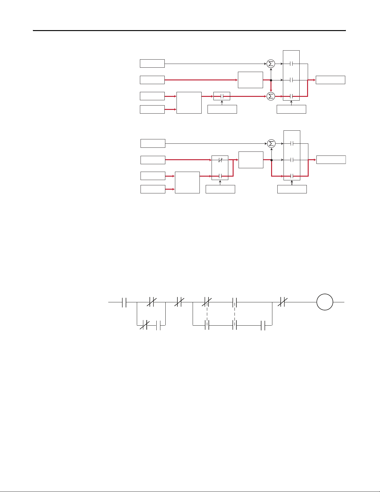
Appendix B Application Notes
Slip Adder
Spd Ref
PI Ref
PI Fbk
Slip Adder
Spd Ref
PI Ref
PI Fbk
Process PI
Controller
Process PI
Controller
PI Enabled
PI Enabled
Linear Ramp
& S-Curve
Linear Ramp
& S-Curve
+
+
+
+
+
+
Slip
Comp
Open
Loop
Process
PI
Speed Control
Slip
Comp
Open
Loop
Process
PI
Speed Control
Spd Cmd
Spd Cmd
Drive
Running
PI Enable
The output of the PI loop can be turned on (enabled) or turned off (disabled).
This control allows the user to determine when the PI loop is providing part or
all of the commanded speed. The logic for enabling the PI loop is shown below.
Drive
Ramping
to Stop
Bit 0 Bit 6
[PI Configuration]
Drive
Jogging
A Digital Input
is Configured
to PI Enable
The drive must be running for the PI loop to be enabled. The loop will be
disabled when the drive is ramping to a stop (unless “Stop Mode” is configured in
[PI Configuration]), jogging or the signal loss protection for the analog input(s)
is sensing a loss of signal.
If a digital input has been configured to “PI Enable,” two events are required to
enable the loop: the digital input must be closed AND bit 0 of the PI Control
parameter must be = 1.
Bit 0 of
[PI Control] = 1
(enabled)
The Configured
Signal Loss
Digital Input
is Closed
The PI Loop
is Enabled
"Enabled" Status
Digital Input
is Reflected
in [PI Status]
Bit 0 = 1
94 Rockwell Automation Publication 20C-PM001F-EN-P - March 2012
Page 95

Application Notes Appendix B
If no digital input is configured to “PI Enable,” then only the Bit 0 = 1 condition
must be met. If the bit is permanently set to a “1”, then the loop will become
enabled as soon as the drive goes into “run”.
PI Pre-load Value
PI Pre-load Value = 0 PI Pre-load Value > 0
PI Enabled
Start at Spd Cmd
PI Output
Spd Cmd
Pre-load to Command Speed
100.0
75.0
50.0
25.0
0.0
-25.0
-50.0
-75.0
Normalized SQRT(Feedback)
-100.0
-100.0 -75.0 -50.0 -25.0 0.0 25.0 50.0 75.0 100.0
Normalized Feedback
Rockwell Automation Publication 20C-PM001F-EN-P - March 2012 95
Page 96

Appendix B Application Notes
Reverse Speed Limit
Figure 6 - [Rev Speed Limit], parameter 454 set to zero
10V
[Maximum
Speed]
Reverse
Speed
[Maximum
Reverse
Speed
Speed]
Minimum
Speed 0
–10V
10V
Minimum
Speed 0
Minimum
Speed = 0
[Maximum
Speed]
[Maximum
Speed]
Forward
Speed
Forward
Speed
–10V
Figure 7 - [Rev Speed Limit], parameter 454 set to a non-zero Value
10V
Note: Minimum speed is not used when
Reverse Speed Limit is set to a non-zero
value.
Reverse
Speed
Reverse
Speed
Limit
Forward
Speed
Maximum
Speed
–10V
96 Rockwell Automation Publication 20C-PM001F-EN-P - March 2012
Page 97

Application Notes Appendix B
Skip Frequency
Figure 8 - Skip Frequency
Frequency
Skip + 1/2 Band
Skip Frequency
Skip – 1/2 Band
Command
Frequency
Drive Output
Frequency
Time
(A)
(B)
(A)
35 Hz
30 Hz
25 Hz
(B)
Some machinery may have a resonant operating frequency that must be avoided
to minimize the risk of equipment damage. To assure that the motor cannot
continuously operate at one or more of the points, skip frequencies are used.
Parameters 084 [Skip Frequency 1] … 086, [Skip Frequency 3] are available to set
the frequencies to be avoided.
The value programmed into the skip frequency parameters sets the center point
for an entire “skip band” of frequencies. The width of the band (range of
frequency around the center point) is determined by parameter 87, [Skip Freq
Band]. The range is split, half above and half below the skip frequency parameter.
If the commanded frequency of the drive is greater than or equal to the skip
(center) frequency and less than or equal to the high value of the band (skip plus
1/2 band), the drive will set the output frequency to the high value of the band.
See (A) in Figure 8
.
If the commanded frequency is less than the skip (center) frequency and greater
than or equal to the low value of the band (skip minus 1/2 band), the drive will
set the output frequency to the low value of the band. See (B) in Figure 8
.
Acceleration and deceleration are not affected by the skip frequencies. Normal
accel/decel will proceed through the band once the commanded frequency is
greater than the skip frequency. See (A) & (B) in Figure 8
. This function affects
only continuous operation within the band.
Rockwell Automation Publication 20C-PM001F-EN-P - March 2012 97
Page 98

Appendix B Application Notes
Skip Frequency Examples
The skip frequency will have hysteresis
so the output does not toggle between
high and low values. Three distinct
bands can be programmed. If none of
the skip bands touch or overlap, each
band has its own high/low limit.
Max. Frequency
Skip Frequency 1
Skip Band 1
If skip bands overlap or touch, the
center frequency is recalculated based
on the highest and lowest band values.
If a skip band(s) extend beyond the max
frequency limits, the highest band
value will be clamped at the max
frequency limit. The center frequency is
recalculated based on the highest and
lowest band values.
If the band is outside the limits, the skip
band is inactive.
Skip Frequency 2
0 Hz
320 Hz.
Skip Frequency 1
Skip Frequency 2
0 Hz
320 Hz.
Max.Frequency
Skip
0 Hz
320 Hz.
Skip Band 2
Adjusted
Skip Band
w/Recalculated
Skip Frequency
Adjusted
Skip Band
w/Recalculated
Skip Frequency
Skip Frequency 1
60 Hz. Max.
Frequency
0 Hz
98 Rockwell Automation Publication 20C-PM001F-EN-P - March 2012
Inactive
Skip Band
Page 99

Application Notes Appendix B
Sleep Wake Mode
This function stops (sleep) and starts (wake) the drive based on separately
configurable analog input levels rather than discrete start and stop signals. by
default, this function is disabled. The following Sleep/Wake modes are available:
• 1 “Direct” - In this mode, the drive will start (wake) when the analog input
signal is greater than or equal to the value set in [Wake Level] and the drive
will stop (sleep) when the analog input signal is less than or equal to the
value in [Sleep Level].
• 2 “Invert” - In this mode, the analog input signal used by the [Wake Level]
and [Sleep Level] parameters is inverted. In this mode, the drive will start
(wake) when the analog input signal is less than or equal to the value set in
[Wake Level] and the drive will stop (sleep) when the analog input signal is
greater than or equal to the value in [Sleep Level].
Definitions:
• Wake - A start command generated when the analog input value remains
above [Wake Level] for a time greater than [Wake Time].
• Sleep - A Stop command generated when the analog input value remains
below [Sleep Level] for a time greater than [Sleep Time].
• Speed Reference – The active speed command to the drive as selected by
drive logic and [Speed Ref x Sel].
• Start Command - A command generated by pressing the Start button on
the HIM, closing a digital input programmed for Start, Run, Run Forward
or Run Reverse.
Rockwell Automation Publication 20C-PM001F-EN-P - March 2012 99
Page 100

Appendix B Application Notes
Is Sleep-Wake
Working?
No
Have these conditions been met?
1. [Sleep-Wake Ref] must be set to the analog input that will control
"Start/Stop" functions.
2. [Sleep-Wake Mode] must = "1, Direct" (Enable) or "2, Invert (Enable)."
3. [Sleep Level] must be less than [Wake Level] in Direct mode (or
greater than [Wake Level] in "Invert" mode).
4. [Speed Ref x Sel] must be set to a speed reference source that will
control the drive. If [Sleep-Wake Ref] = [Speed Ref x Sel], the same
analog signal will control start/stop and speed reference.
5. At least one of the following must be programmed for [Digital Inx Sel]:
"Stop," "Enable," "Start," "Run," "Run Forward," "Run Reverse."
Ye s
No
Meet all Conditions!
Decrease Analog Input
Signal and wait for a time
period greater than or
equal to [Wake Time].
Reset Fault
Run, Run Forward
or Run Reverse
Open & Close Input
No
Is Analog Signal Less
than or equal to [Wake Level]?
and for time period greater than
or equal to [Wake Time]
Ye s Ye s
Ye s
Did a Drive
Fault Occur?
No
Is Required Input Closed?
No
(Stop, Enable, Run)
Ye s
Which Mode is Selected?
DirectInvert
"Invert" or "Direct"
Is Analog Signal Greater
than or equal to [Wake Level]?
and for time period greater than
or equal to [Wake Time]
Was a Stop Issued?
Which Required Input
was Chosen?
or
Power Cycled?
Ye s
Issue a Start Command
(HIM, Network or TB)
Close Input
No
No
Stop or Enable
Increase Analog Input
Signal and wait for a time
period greater than or
equal to [Wake Time].
Consult Factory
Drive Running?
No
100 Rockwell Automation Publication 20C-PM001F-EN-P - March 2012
Consult Factory
 Loading...