

Page 1
Installation Instructions
PowerFlex 700 Adjustable Frequency AC Drive – Frames 0…6
0.37…132 kW (0.5…200 Hp)
This document explains the 5 BASIC STEPS needed to install and perform a
Basic Start-Up of the PowerFlex 700 (Series A or B) AC drive. A Human
Interface Module (HIM) is required to perform the Basic Start-Up routine
covered in this manual.
The information provided is intended for qualified installers only.
Additional Resources
These documents contain additional information concerning related products
from Rockwell Automation.
Resource Description
PowerFlex 700 Standard Control User Manual, publication
20B-UM001
PowerFlex 700 Vector Control User Manual (v4.001 & up),
publication 20B-UM002
PowerFlex 700 AC Drive Technical Data, publication
20B-TD001
PowerFlex Comm Adapter Manuals, publication
20COMM-UM…
PowerFlex 70 and PowerFlex 700 Reference Manual,
publication PFLEX-RM001
PowerFlex 70 Enhanced Control and PowerFlex 700 Vector
Control Reference Manua l, publication PFLEX-RM004
Wiring and Grounding Guidelines for Pulse Width
Modulated (PWM) AC Drives, publication DRIVES-IN001
Safety Guidelines for the Application, Installation and
Maintenance of Solid State Control, publication SGI-1.1
Guarding Against Electrostatic Damage, publication
8000-4.5.2
Product Certifications website, http://ab.com
Provides detailed information on:
• Parameters and programming
• Faults, alarms, and troubleshooting
This publication provides detailed drive specifications,
option specifications and input protection device ratings.
These publications provide information on configuring,
using, and troubleshooting PowerFlex communication
adapters.
These publications provide detailed application specific
information for programming and configuring the
PowerFlex 700 drive.
Provides basic information needed to properly wire and
ground PWM AC drives.
Provides general guidelines for the application,
installation, and maintenance of solid-state control.
Provides practices for guarding against Electrostatic
damage (ESD)
Provides declarations of conformity, certificates, and
other certification details.
You can view or download publications at
http://www.rockwellautomation.com/literature/
. To order paper copies of
technical documentation, contact your local Allen-Bradley distributor or
Rockwell Automation sales representative.
Page 2

PowerFlex 700 Adjustable Frequency AC Drive – Frames 0…6
Allen-Bradley Drives Technical Support
Use the contacts below for PowerFlex 700 technical support including spare parts
information.
Online at… By Email at… By Telephone at…
www.ab.com/support/abdrives support@drives.ra.rockwell.com 262-512-8176
Installation Instructions in Other Languages
English This instruction sheet is available in multiple languages at
http://www.rockwellautomation.com/literature
Select publication language and type “20B-IN019” in the search field.
Deutsch Dieses Instruktionsblatt kann in mehreren Sprachen unter
http://www.rockwellautomation.com/literature
Bitte Ihre Sprache anwählen und “20B-IN019” im Suchfeld eintippen.
Français Ces instructions sont disponibles dans différe ntes langues à l’adresse suivante:
Italiano La presente scheda d’istruzione è disponibile in varie lingue sul sito
Español Puede encontrar esta hoja de instrucciones en varios idiomas en
Português Esta folha de instruções está disponível em várias línguas em
Chinese
(simplified)
http://www.rockwellautomation.com/literature.
Sélectionner la langue puis taper << 20B-IN019 >> dans le champ de recherche.
http://www.rockwellautomation.com/literature
Selezionare la lingua desiderata e digitare “20B-IN019” nel campo di ricerca.
http://www.rockwellautomation.com/literature
Seleccione el idioma de publicación y escriba “20B-IN019” en el campo de búsqueda.
http://www.rockwellautomation.com/literature.
Seleccione a língua de publicação e entre com “20B-IN019” no espaço de busca.
从以下网页可以获得本说明书的多种语言的版本 :
http://www.rockwellautomation.com/literature
请选择出版物的语言 , 并在搜索栏输入 “20B-IN019 印?
.
gelesen werden.
.
.
?
2 Rockwell Automation Publication 20B-IN019E-EN-P - July 2013
Page 3

PowerFlex 700 Adjustable Frequency AC Drive – Frames 0…6
Table of Contents
Catalog Number Explanation . . . . . . . . . . . . . . . . . . . . . . . . . . . . . . . . . . . . . . . . . . . . . 4
Step 1: Read the Precautions and General Information . . . . . . . . . . . . . . . . . . . . . 5
EMC Instructions . . . . . . . . . . . . . . . . . . . . . . . . . . . . . . . . . . . . . . . . . . . . . . . . . . . . . . . 7
Step 2: Mount the Drive. . . . . . . . . . . . . . . . . . . . . . . . . . . . . . . . . . . . . . . . . . . . . . . . 9
Accessing the Terminals . . . . . . . . . . . . . . . . . . . . . . . . . . . . . . . . . . . . . . . . . . . . . . . . . . 9
Environment . . . . . . . . . . . . . . . . . . . . . . . . . . . . . . . . . . . . . . . . . . . . . . . . . . . . . . . . . . . . 9
Minimum Mounting Clearances . . . . . . . . . . . . . . . . . . . . . . . . . . . . . . . . . . . . . . . . . 10
Dimensions . . . . . . . . . . . . . . . . . . . . . . . . . . . . . . . . . . . . . . . . . . . . . . . . . . . . . . . . . . . .11
Step 3: Wire the Drive – Power . . . . . . . . . . . . . . . . . . . . . . . . . . . . . . . . . . . . . . . . . 21
Special Considerations . . . . . . . . . . . . . . . . . . . . . . . . . . . . . . . . . . . . . . . . . . . . . . . . . . 21
Cable Types Acceptable for 200…600 Volt Installations . . . . . . . . . . . . . . . . . . . .22
Single-Phase Input Power. . . . . . . . . . . . . . . . . . . . . . . . . . . . . . . . . . . . . . . . . . . . . . . . 24
Selecting/Verifying Fan Voltage (Frames 5…6 Only) . . . . . . . . . . . . . . . . . . . . . . .26
Auxiliary Control Power Supply. . . . . . . . . . . . . . . . . . . . . . . . . . . . . . . . . . . . . . . . . .27
Power Terminal Blocks . . . . . . . . . . . . . . . . . . . . . . . . . . . . . . . . . . . . . . . . . . . . . . . . . .28
Power and Ground Wiring. . . . . . . . . . . . . . . . . . . . . . . . . . . . . . . . . . . . . . . . . . . . . . .31
Motor Overload Protection. . . . . . . . . . . . . . . . . . . . . . . . . . . . . . . . . . . . . . . . . . . . . .32
Drive, Fuse & Circuit Breaker Ratings . . . . . . . . . . . . . . . . . . . . . . . . . . . . . . . . . . . .33
Output Devices. . . . . . . . . . . . . . . . . . . . . . . . . . . . . . . . . . . . . . . . . . . . . . . . . . . . . . . . .41
Using Input/Output Contactors . . . . . . . . . . . . . . . . . . . . . . . . . . . . . . . . . . . . . . . . .42
Disconnecting MOVs and Common Mode Capacitors. . . . . . . . . . . . . . . . . . . . . 43
Step 4: I/O Wiring . . . . . . . . . . . . . . . . . . . . . . . . . . . . . . . . . . . . . . . . . . . . . . . . . . . . 52
I/O Terminals . . . . . . . . . . . . . . . . . . . . . . . . . . . . . . . . . . . . . . . . . . . . . . . . . . . . . . . . . .53
I/O Wiring Examples . . . . . . . . . . . . . . . . . . . . . . . . . . . . . . . . . . . . . . . . . . . . . . . . . . .56
Hardware Enable Circuitry (Vector Control Only) . . . . . . . . . . . . . . . . . . . . . . . .57
Encoder Interface Option (Vector Control Only). . . . . . . . . . . . . . . . . . . . . . . . . .58
Reference Control . . . . . . . . . . . . . . . . . . . . . . . . . . . . . . . . . . . . . . . . . . . . . . . . . . . . . .59
Step 5: Start-Up Check List . . . . . . . . . . . . . . . . . . . . . . . . . . . . . . . . . . . . . . . . . . . . 62
Prepare For Drive Start-Up . . . . . . . . . . . . . . . . . . . . . . . . . . . . . . . . . . . . . . . . . . . . . .62
Supplemental Information. . . . . . . . . . . . . . . . . . . . . . . . . . . . . . . . . . . . . . . . . . . . 65
Using PowerFlex Drives w/Regen Units. . . . . . . . . . . . . . . . . . . . . . . . . . . . . . . . . . . 65
DC Input (Common Bus) and Precharge Notes . . . . . . . . . . . . . . . . . . . . . . . . . . .65
Human Interface Module (HIM) Overview . . . . . . . . . . . . . . . . . . . . . . . . . . . . . . .66
Start-Up Routines. . . . . . . . . . . . . . . . . . . . . . . . . . . . . . . . . . . . . . . . . . . . . . . . . . . . . . .67
Drive Status Indicators . . . . . . . . . . . . . . . . . . . . . . . . . . . . . . . . . . . . . . . . . . . . . . . . . . 70
Common I/O Programming Changes . . . . . . . . . . . . . . . . . . . . . . . . . . . . . . . . . . . . 71
Troubleshooting . . . . . . . . . . . . . . . . . . . . . . . . . . . . . . . . . . . . . . . . . . . . . . . . . . . . . . . . 72
Common Symptoms and Corrective Actions. . . . . . . . . . . . . . . . . . . . . . . . . . . . . .74
Manually Clearing Faults . . . . . . . . . . . . . . . . . . . . . . . . . . . . . . . . . . . . . . . . . . . . . . . .76
Rockwell Automation Publication 20B-IN019E-EN-P - July 2013 3
Page 4
PowerFlex 700 Adjustable Frequency AC Drive – Frames 0…6
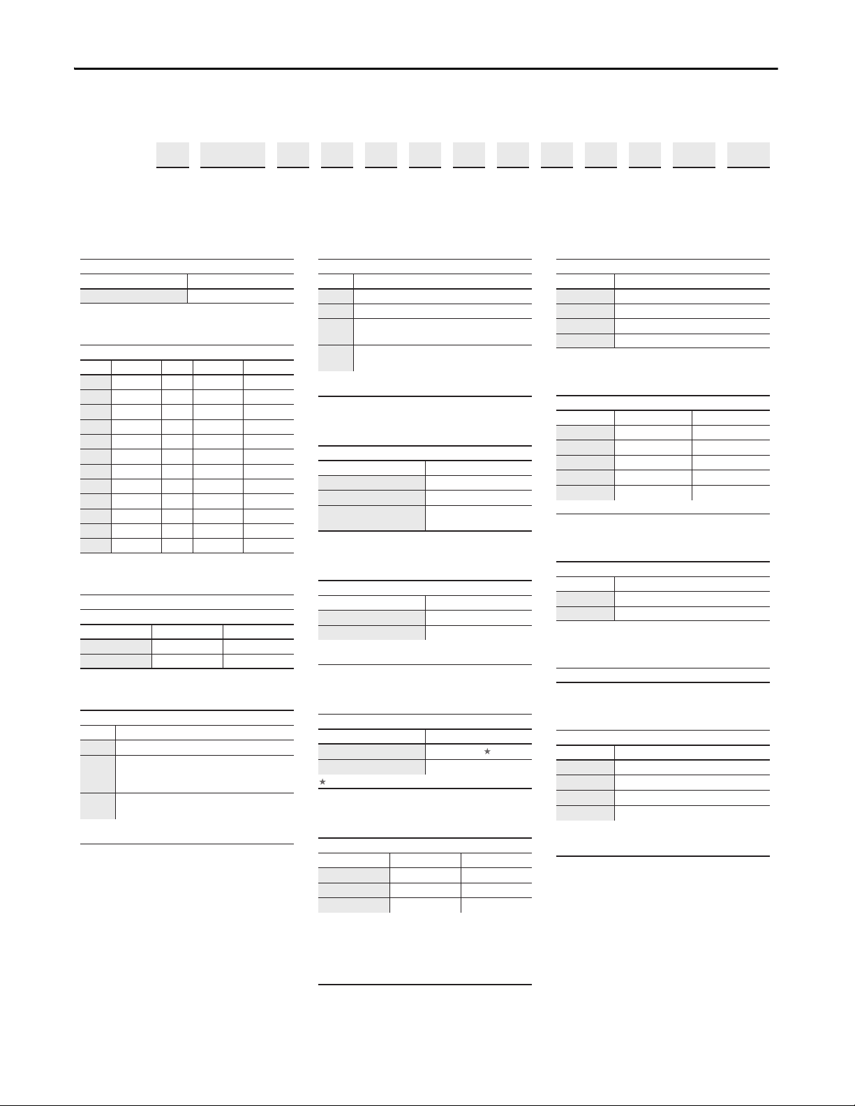
Catalog Number Explanation
20B D 2P1 A 3 A Y N A E C 0 NN AD
abcdefghijklmn
a
Drive
Code Type
20B PowerFlex 700
b
Voltage Rating
Code Voltage Ph. Prechg. Frames
B 240V AC 3 - 0…6
C 400V AC 3 - 0…6
D 480V AC 3 - 0…6
E 600V AC 3 - 0…6
F 690V AC 3 - 5…6
H 540V DC - N 5…6
J 650V DC - N 5…6
N 325V DC - Y 5…6
P 540V DC - Y 5…6
R 650V DC - Y 5…6
T 810V DC - Y 5…6
W 932V DC - Y 5…6
c
ND Output Rating
Example
Code Amps kW (Hp)
2P2 2.2 0.37 (0.5)
022 22 5.5 (7.5)
e
HIM
Code Operator Interface
0 Blank Cover
3 LCD Display, Full Numeric Keypad
Remote (Panel Mount), IP66, NEMA/UL
J ♦
K ♦
♦ Available with Frames 5…6 Stand-Alone IP54
drives (Enclosur
T
ype 12 Full Numeric LCD HIM
Remote (Panel Mount), IP66, NEMA/UL
T
ype 12 Prog. Only LCD HIM
e Code "G").
f
Documentation
Code Type
A Manual
N No Manual
Q
No Shipping Package
(Internal Use Only)
g
Brake
Code w/Brake IGBT ‡
YYes
NNo
‡ Brake IGBT is standard on Frames 0-3,
optional on Frames 4-6.
j
Comm Slot
Code Network Type
C ControlNet (Coax)
D DeviceNet
E EtherNet/IP
N None
k
Control & I/O
Code Control I/O Volts
A Standard 24V DC/AC
B Standard 115V AC
C
D
N Standard None
Δ Vector Control Option utilizes DPI Only.
Vector Δ
Vector Δ
24V DC
115V AC
l
Feedback
Code Type
0 None
1 Encoder, 12V/5V
m
Future Use
d
Enclosure
Code Enclosure
A IP20, NEMA/UL Type 1
Open/Flange Mount
ont: IP00, NEMA/UL Type Open
F ♠
G ♠
♠ Only available for Frame 5 & Frame 6 drives,
400…690V
Fr
Back/Heatsink: IP54, NEMA Type 12
Stand-Alone/Wall Mount
IP54, NEMA/UL T
.
ype 12
Internal Braking Resistor
Code w/Resistor
Y
NNo
Not available for Frame 3 drives or larger.
Code CE Filter § CM Choke
A Yes Yes
B #
NNoNo
§ Note: 600V class drives below 77 Amps
(Frames 0-4) ar
Voltage Directive. It is the responsibility of the
user to determine compliance to the EMC
directive.
# Only available for 208…240V Frame 0-3 drives.
h
Ye s
i
Emission
Ye s N o
e declared to meet the Low
4 Rockwell Automation Publication 20B-IN019E-EN-P - July 2013
n
Special Firmware (Frames 0…6 Only)
Code Type
AD ♦
AE ♦
AX ♦
BA ♦
♦ Must be used with Vector Control option C or
D (Position k). Positions m-n ar
when custom firmware is supplied.
60 Hz Maximum
Cascading Fan/Pump Control
82 Hz Maximum
Pump Off (for pump jack)
e only required
Page 5
PowerFlex 700 Adjustable Frequency AC Drive – Frames 0…6
Step 1: Read the Precautions and General Information
Qualified Personnel
ATT EN TI ON : Only qualified personnel familiar with adjustable frequency AC
drives and associated machinery must plan or implement the installation, startup and subsequent maintenance of the system. Failure to comply can result in
personal injury and/or equipment damage.
Personal Safety
ATT EN TI ON : To avoid an electric shock hazard, verify that the voltage on the
bus capacitors has discharged before performing any work on the drive.
Measure the DC bus voltage at the following points (refer to pages 28
for locations):
30
• +DC and -DC terminals of the Power Terminal Block
• +DC terminal of the Power Terminal Block and the chassis
• -DC terminal of the Power Terminal Block and the chassis
The voltage must be zero for all three measurements.
through
ATT EN TI ON : Risk of injury or equipment damage exists. DPI or SCANport host
products must not be directly connected together via 1202 cables.
Unpredictable behavior can result if two or more devices are connected in this
manner.
ATT EN TI ON : The drive start/stop/enable control circuitry includes solid state
components. If hazards due to accidental contact with moving machinery or
unintentional flow of liquid, gas or solids exist, an additional hardwired stop
circuit can be required to remove the AC line to the drive. An auxiliary braking
method can be required.
ATT EN TI ON : Loss of control in suspended load applications can cause personal
injury and/or equipment damage. Loads must always be controlled by the drive
or a mechanical brake. Parameters 600…611 are designed for lifting/torque
proving applications. It is the responsibility of the engineer and/or end user to
configure drive parameters, test any lifting functionality and meet safety
requirements in accordance with all applicable codes and standards.
Rockwell Automation Publication 20B-IN019E-EN-P - July 2013 5
Page 6
PowerFlex 700 Adjustable Frequency AC Drive – Frames 0…6
Product Safety
ATT EN TI ON : An incorrectly applied or installed drive can result in component
damage or a reduction in product life. Wiring or application errors, such as,
undersizing the motor, incorrect or inadequate AC supply, or excessive ambient
temperatures can result in malfunction of the system.
ATT EN TI ON : This drive contains ESD (Electrostatic Discharge) sensitive parts
and assemblies. Static control precautions are required when installing, testing,
servicing or repairing this assembly. Component damage can result if ESD
control procedures are not followed. If you are not familiar with static control
procedures, reference Guarding Against Electrostatic Damage, publication
8000-4.5.2 or any other applicable ESD protection handbook.
ATT EN TI ON : The “adjust freq” portion of the bus regulator function is
extremely useful for preventing nuisance overvoltage faults resulting from
aggressive decelerations, overhauling loads, and eccentric loads. It forces the
output frequency to be greater than commanded frequency, while the bus
voltage is increasing toward a level that causes a fault. However, it can also
cause either of the following two conditions to occur.
• Fast positive changes in input voltage (more than a 10% increase within 6
minutes) can cause uncommanded positive speed changes. However an
“OverSpeed Limit” fault (F25) occurs if the speed reaches [Maximum Speed] +
[Overspeed Limit], (parameters 82 and 83). If this condition is unacceptable,
action must be taken to 1) limit supply voltages within the specification of the
drive and, 2) limit fast positive input voltage changes to less than 10%.
Without taking such actions, if this operation is unacceptable, the “adjust freq”
portion of the bus regulator function must be disabled (see parameters 161
and 162).
• Actual deceleration times can be longer than commanded deceleration times.
However, a “Decel Inhibit” fault (F24) is generated if the drive stops
decelerating altogether. If this condition is unacceptable, the “adjust freq”
portion of the bus regulator must be disabled (see parameters 161 and 162). In
addition, installing a properly sized dynamic brake resistor provides equal or
better performance in most cases.
Important: These faults are not instantaneous. Test results have shown that they
can take between 2…12 seconds to occur.
6 Rockwell Automation Publication 20B-IN019E-EN-P - July 2013
Page 7

PowerFlex 700 Adjustable Frequency AC Drive – Frames 0…6
EMC Instructions
CE Conformity
Conformity with the Low Voltage (LV) Directive and Electromagnetic
Compatibility (EMC) Directive has been demonstrated by using harmonized
European Norm (EN) standards published in the Official Journal of the
(1)
European Communities. PowerFlex Drives
listed below when installed according to the information supplied in this
publication and the Wiring & Grounding Guidelines Manual.
CE Declarations of Conformity are available online at:
http://www.rockwellautomation.com/rockwellautomation/certification.
Low Voltage Directive (73/23/EEC)
• EN50178 Electronic equipment for use in power installations.
EMC Directive (89/336/EEC)
• EN61800-3 Adjustable speed electrical power drive systems Part 3: EMC
product standard including specific test methods.
comply with the EN standards
General Notes
• Some drives are equipped with an adhesive label on the top of the drive. If
the adhesive label is removed from the top of the drive, the drive must be
installed in an enclosure with side openings less than 12.5 mm (0.5 in.) and
top openings less than 1.0 mm (0.04 in.) to maintain compliance with the
LV Directive.
• The motor cable must be kept as short as possible to avoid electromagnetic
emission as well as capacitive currents.
• Use of line filters in ungrounded systems is not recommended.
• PowerFlex drives can cause radio frequency interference if used in a
residential or domestic environment. The installer is required to take
measures to prevent interference, in addition to the essential requirements
for CE compliance listed below, if necessary.
• Conformity of the drive with CE EMC requirements does not guarantee
an entire machine or installation complies with CE EMC requirements.
Many factors can influence total machine/installation compliance.
• PowerFlex drives can generate conducted low frequency disturbances
(harmonic emissions) on the AC supply system.
• When operated on a public supply system, it is the responsibility of the
installer or user to ensure, by consultation with the distribution network
operator and Rockwell Automation, if necessary, that applicable
requirements have been met.
(1) 600V class drives below 77A (Frames 0…4) are declared to meet the essential requirements of the Low Voltage D irective. It is the
responsibility of the user to determine compliance to the EMC directive.
Rockwell Automation Publication 20B-IN019E-EN-P - July 2013 7
Page 8

PowerFlex 700 Adjustable Frequency AC Drive – Frames 0…6
Essential Requirements for CE Compliance
Conditions 1…6 listed below must be satisfied for PowerFlex drives to meet the
requirements of EN61800-3.
1. Standard PowerFlex 700 CE compatible Drive.
2. Review important precautions/attention statements throughout this
publication and the User Manual before installing the drive.
3. Grounding as described in this publication and the User Manual.
4. Output power, control (I/O) and signal wiring must be braided, shielded
cable with a coverage of 75% or better, metal conduit, or equivalent
attenuation.
5. All shielded cables must terminate with the proper shielded connector.
6. The following conditions:
– First Environment Restricted Distribution - For any drive and option a
filter is required for motor cable lengths greater than 150 m (492 ft.).
– Second Environment (Industrial) - Motor cable is limited to 30 m (98
ft.) for installations without additional external line filters.
External filters for First Environment installations and increasing motor cable
lengths in Second Environment installations are available. Roxburgh models
KMFA (RF3 for UL installations) and MIF or Schaffner FN3258 and FN258
models are recommended. Refer to Ta b l e 1
http://www.mtecorp.com
Table 1 - PowerFlex 700 Recommended Filters
Manufacturer Frame
Deltron 0 MIF316 — 150
1 KMF325A — 150
2 KMF350A 200 150
2 without DC Common Mode Capacitor KMF350A 176 150
3 KMF370A 150 100
3 without DC Common Mode Capacitor KMF370A 150 100
Schaffner 0 FN358-16-45 —
1 FN358-30-47 —
2 FN358-42-47 50
2 without DC Common Mode Capacitor FN358-42-47 150
3 FN358-75-52 100
3 without DC Common Mode Capacitor FN358-75-52 150
(USA) or http://www.schaffner.com, respectively.
and http://www.dem-uk.com and
Manufacturer Part
No.
KMF318A — 100
Class A
(Meters)
Class B
(Meters)
8 Rockwell Automation Publication 20B-IN019E-EN-P - July 2013
Page 9
PowerFlex 700 Adjustable Frequency AC Drive – Frames 0…6
IMPORTANT
Esc
7 8 9
4 5 6
1 2 3
.
0 +/-
Sel
Jog
Alt
POWER
STS
PORT
MOD
NET A
NET B
Exp
Param #
S.M.A.R.T.
Exit
Lang
Auto / Man
Remove
HOT surfaces can cause severe burns
CAUTION
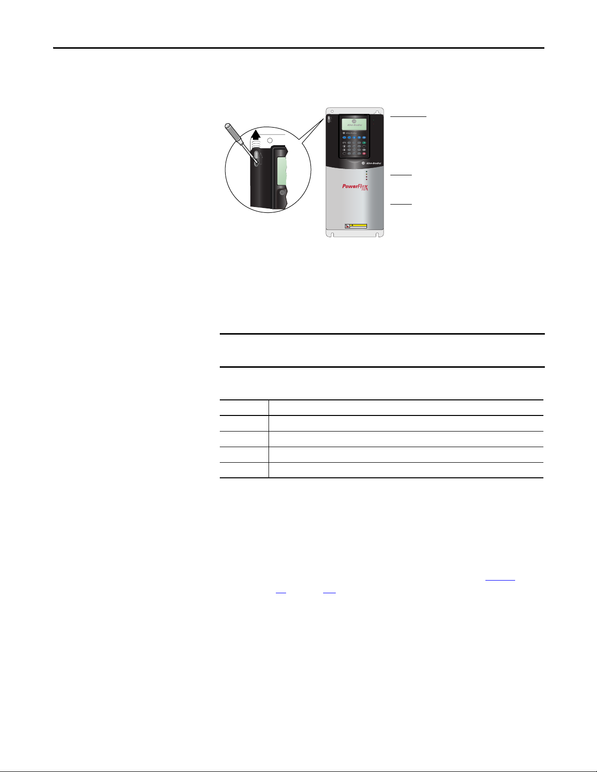
Frames 0…4
Locate the slot in the upper left corner. Slide the locking
tab up and swing the cover open. Special hinges allow
cover to move away from drive a nd lay on top of adjacent
drive (if present). See below for frame 4 access panel
removal.
Frame 5
Slide the locking tab up, loosen the right-hand cover
screw and remove. See below for access panel removal.
Frame 6
Loosen 2 screws at bottom of drive cover. Carefully slide
bottom cover down & out. Loosen the 2 screws at top of
cover and remove.
Step 2: Mount the Drive
Accessing the Terminals
Opening the Cover
Cable Entry Plate Removal
If additional wiring access is needed, the Cable Entry Plate on 0…3 Frame drives
can be removed. Simply loosen the screws securing the plate to the chassis. The
slotted mounting holes assure easy removal.
Removing the Cable Entry Plate limits the maximum ambient temperature to
40 °C (104 °F).
Power Wiring Access Panel Removal
Frame Removal Procedure (Replace when wiring is complete)
0, 1, 2 & 6 Part of front cover, see above.
3 Open front cover and gently tap/slide cover down and out.
4 Loosen the 4 screws and remove.
5 Remove front cover (see above), gently tap/slide panel up and out.
Environment
Operating Temperatures
PowerFlex 700 drives are designed to operate at 0 to 40 °C ambient. To operate
the drive in installations between 41 and 50 °C (106…122 °F), see Ta b l e 2
refer to pages 34
Rockwell Automation Publication 20B-IN019E-EN-P - July 2013 9
through 41 for exceptions.
and
Page 10
PowerFlex 700 Adjustable Frequency AC Drive – Frames 0…6
101.6 mm
(4.0 in.)
101.6 mm
(4.0 in.)
50.8 mm
(2.0 in.)
101.6 mm
(4.0 in.)
101.6 mm
(4.0 in.)
PWR
STS
PORT
MOD
NET A
NET B
PWR
STS
PORT
MOD
NET A
NET B
Airflow through the drive
must not be impeded.
Refer to pages 11
through 20
for detailed
dimension information.
No Adhesive Label
(see Tab le 2 )
With Adhe sive Label
(see Tab le 2
)
Table 2 - Acceptable Surrounding Air Temperature & Required Actions
Enclosure Rating Temperature Range Drive
IP20, NEMA/UL Type 1
(with Top Label)
IP20, NEMA/UL Type Open
(Top Label Removed)
(1)
(1)
IP00, NEMA/UL Type Open
(Top Label & Vent Plate Removed)
Flange Mount
Front: IP00, NEMA/UL Type Open
Back/Heat Sink: IP54, NEMA/UL Type 12
Stand-alone/Wall Mount
IP54, NEMA/UL Type 12
(1) Removing the adhesive top label from the drive changes the NEMA/UL enclosure rating from Type 1 to Open. Frames 5 and 6 do not
have a top label.
(2) Refer to pages 34 through 41 for exceptions.
(3) To remove vent plate (see page 11 for location), lift top edge of plate from the chassis. Rotate the plate out from the back plate.
0…40 °C (0…104 °F) Frames 0…4, All Ratings
0…50 °C (0…122 °F) Frames 5…6, Most Ratings
0…50 °C (0…122 °F) Frames 0…6, Most Ratings
0…45 °C (0…113 °F) 20BC072 Only
0…50 °C (0…122 °F) 20BC072 Only
0…55 °C (0…131 °F) Front (Inside Encl.)
Frames 5…6
(3)
0…40 °C (0…104 °F) Back (External)
0…40 °C (0…104 °F) Frames 5…6
(2)
(2)
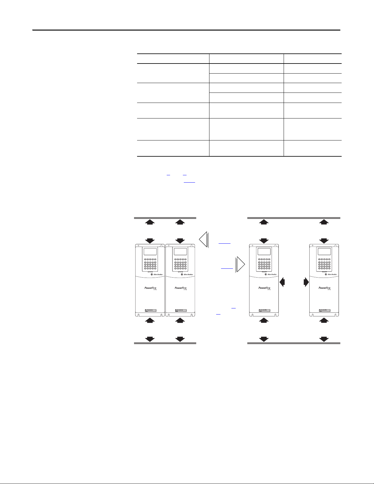
Minimum Mounting Clearances
101.6 mm
(4.0 in.)
101.6 mm
(4.0 in.)
Specified vertical clearance requirements (indicated above) are intended to be
from the drive to the closest object that can restrict airflow through the drive heat
sink and chassis. The drive must be mounted in a vertical orientation as shown
and must make full contact with the mounting surface. Do not use standoffs or
spacers. In addition, inlet air temperature must not exceed the product
specification.
101.6 mm
(4.0 in.)
PWR
STS
PORT
MOD
NET A
NET B
PWR
STS
PORT
MOD
NET A
NET B
101.6 mm
(4.0 in.)
10 Rockwell Automation Publication 20B-IN019E-EN-P - July 2013
Page 11
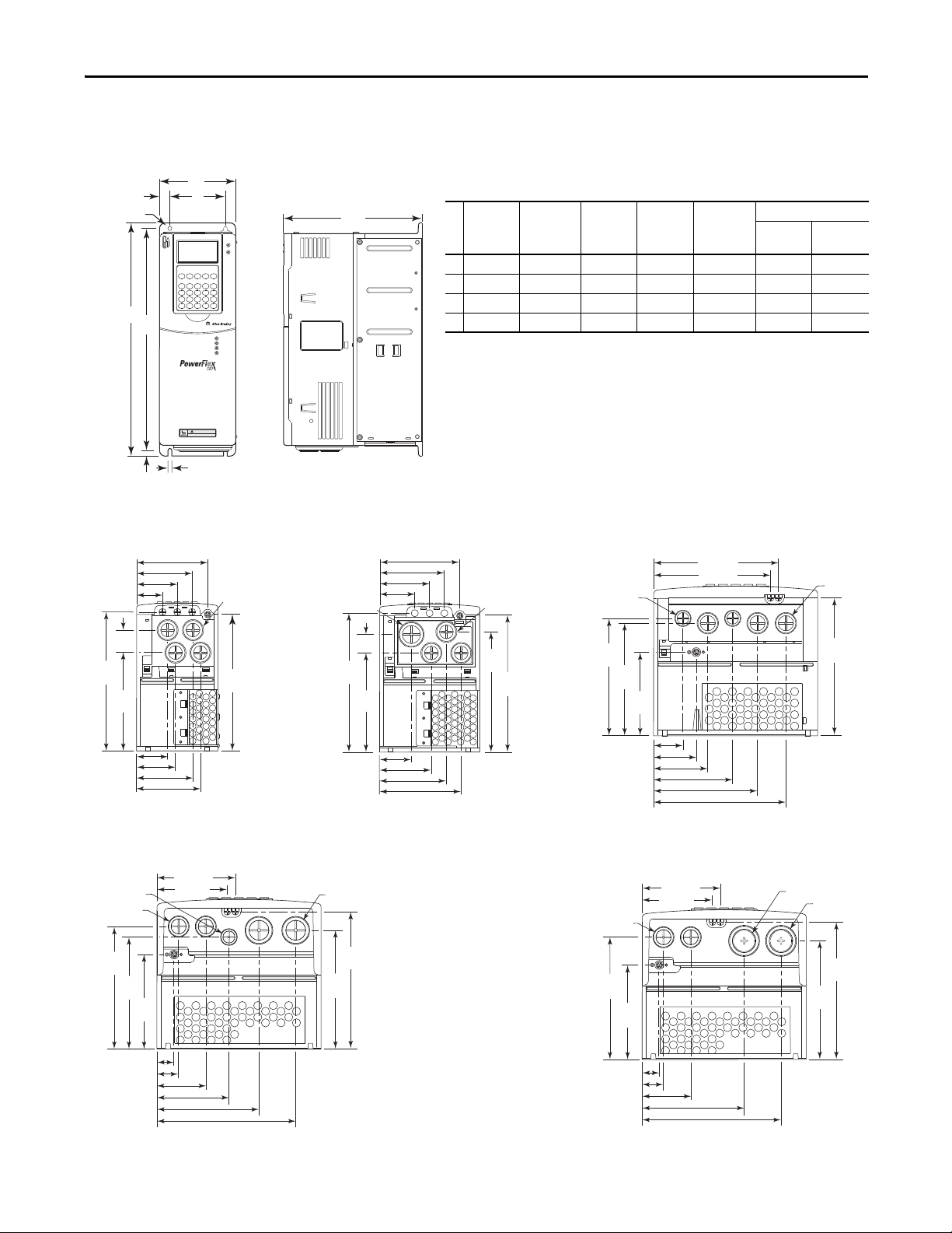
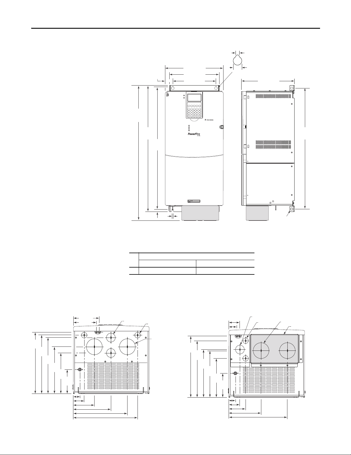
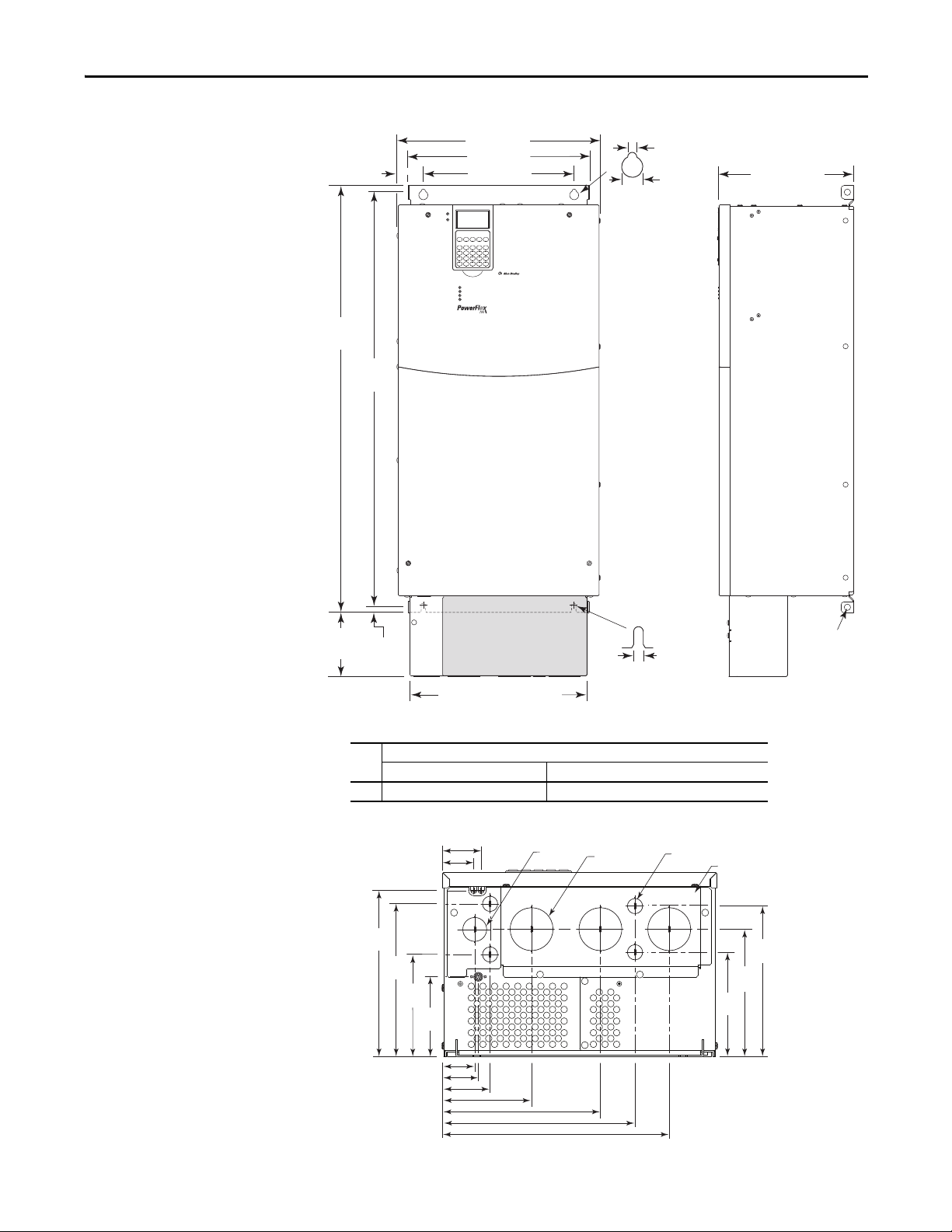
Dimensions
C
A
D
15.0 (0.59)
5.8 (0.23) dia.
E
8.0
(0.31)
5.5 (0.22) x 3 - Frames 0…1
7.0 (0.28) x 3 - Frames 2…3
B
HOT surfaces can cause severe burns
CAUTION
Frame 0 Shown
Frame
AB CDE
Weight
(1)
kg (lbs. )
(1) Weights include HIM and Standard I/O.
Drive
Drive &
Packagi ng
0 110.0 (4.33) 336.0 (13.23) 200.0 (7.87) 80.0 (3.15) 320.0 (12.60) 5.22 (11.5) 8 .16 (18)
1 135.0 (5.31) 336.0 (13.23) 200.0 (7.87) 105.0 (4.13) 320.0 (12.60) 7.03 (15.5) 9.98 (22)
2 222.0 (8.74) 342.5 (13.48) 200.0 (7.87) 192.0 (7.56) 320.0 (12.60) 12.52 (27.6) 15.20 (33.5)
3 222.0 (8.74) 517.5 (20.37) 200.0 (7.87) 192.0 (7.56) 495.0 (19.49) 18.55 (40.9) 22.68 (50)
Dimensions are in millimeters and (inches)
94.7 (3.73)
105.3 (4.15)
127.7
(5.03)
151.1
(5.95)
160.1
(6.30)
165.1
(6.50)
184.5
(7.26)
22.2 (0.87) Dia.
28.7 (1.13) Dia.
2 Places
37.3 (1.47) Dia.
2 Places
66.0 (2.60)
97.0 (3.82)
137.2 (5.40)
187.0 (7.36)
22.7 (0.89)
29.0 (1.14)
Frame 3
All except 50 Hp, 480V (37 kW, 400V)
Frame 3
50 Hp, 480V (37 kW, 400V) Normal Duty Drive
132.9
(5.23)
187.5
(7.38)
30.2
(1.19)
41.9 (1.65)
56.1 (2.21)
96.0 (3.78)
75.9 (2.99)
96.0 (3.78)
55.0 (2.17)
75.0 (2.95)
35.0 (1.38)
22.2 (0.87) Dia.
4 Places
185.0
(7.28)
133.3
(5.25)
187.6
(7.39)
25.5
(1.00)
22.2 (0.87) Dia.
3 Places
185.1
(7.29)
162.3
(6.39)
43.0 (1.69)
70.0 (2.76)
96.0 (3.78)
75.9 (2.99)
28.6 (1.13) Dia.
108.5 (4.27)
67.5 (2.66)
47.5 (1.87)
87.5 (3.44)
167.5 (6.59)
156.9 (6.18)
150.9
(5.94)
184.8
(7.28)
157.5
(6.20)
112.1
(4.41)
22.4 (0.88) Dia.
2 Places
28.7 (1.13) D
3 Places
39.3 (1.55)
57.2 (2.25)
72.7 (2.86)
106.0 (4.17)
139.4 (5.49)
177.4 (6.98)
Frame 2Frame 1Frame 0
Frames 0…3 – IP20, NEMA/UL Type 1
PowerFlex 700 Adjustable Frequency AC Drive – Frames 0…6
.
Vent Plate
34.9 (1.37) Dia.
2 Places
46.7 (1.84) Dia.
2 Places
160.1
(6.30)
184.5
(7.26)
105.3 (4.15)
94.7 (3.73)
28.7 (1.13) Dia.
2 Places
165.1
(6.50)
127.7
(5.03)
22.7 (0.89)
29.0 (1.14)
66.0 (2.60)
130.0 (5.12)
186.0 (7.32)
Rockwell Automation Publication 20B-IN019E-EN-P - July 2013 11
Page 12
PowerFlex 700 Adjustable Frequency AC Drive – Frames 0…6
Dimensions are in millimeters
and (inches)
54.1 (2.13) Dia.
2 Places
47.0 (1.85) Dia.
2 Places
28.7 (1.13) Dia.
2 Places
141.9
(5.59)
105.1
(4.14)
157.9
(6.21)
177.9
(7.00)
189.7
(7.47)
22.2 (0.87) Dia.
26.8 (1.06)
36.8 (1.45)
50.7 (2.00)
63.8 (2.51)
112.0 (4.41)
180.0 (7.09)
65.3 (2.57)
76.0 (2.99)
Frame 4 – IP20, NEMA/UL Type 1
15.0 (0.59)
7.0 (0.28) dia.
758.8
(29.87)
738.2
(29.06)
220.0 (8.66)
192.0 (7.56)
201.7 (7.94)
8.0
(0.31)
Approx. Weight
Drive Drive & Packaging
Frame
Lifting Holes x 4
(1)
kg (lbs. )
4 24.49 (54.0) 29.03 (64.0)
(1) Weights include HIM and Standard I/O.
7.0 (0.28) x 3
12 Rockwell Automation Publication 20B-IN019E-EN-P - July 2013
Page 13
Frame 5 – IP20, NEMA/UL Type 1
HOT surfaces can cause severe burns
CAUTION
625.0
(24.61)
12.5
(0.49)
6.5
(0.26)
644.5
(25.37)
225.0 (8.86)
308.9 (12.16)
259.1 (10.20)
15.0 (0.59)
6.5 (0.26)
37.6 (1.48)
617.0
(24.29)
689.6
(27.15)
275.4 (10.84)
Lifting Holes x 4
12.7 (0.50) Dia.
Junction Box
Dimensions are in millimeters and (inches)
96.0
(3.78)
153.5
(6.04)
184.3
(7.26)
188.5
(7.42)
223.5
(8.80)
241.9
(9.52)
31.9 (1.26)
42.6 (1.68)
22.2 (0.87) Dia.
2 Places
62.7 (2.47) Dia.
2 Places
Removable Junction Box
34.9 (1.37) Dia.
44.0 (1.73)
66.4 (2.61)
128.0 (5.04)
232.3 (9.15)
28.0 (1.10)
30 kW, 208V (40 Hp, 240V)
55 kW, 400V (75 Hp, 480V)
45/55/75 kW, 690V (75 Hp, 600V)
37 kW, 208V (50 Hp, 240V )
75 kW, 400V (100 Hp, 480V )
90kW, 690V (100 Hp, 600V)
PowerFlex 700 Adjustable Frequency AC Drive – Frames 0…6
241.9
(9.52)
229.5
(9.04)
220.0
(8.66)
184.0
(7.24)
159.5
(6.28)
150.0 (5.91)
215.0 (8.46)
255.0 (10.04)
96.0
(3.78)
28.0 (1.10)
45.0 (1.77)
85.0 (3.35)
104.0 (4.09)
93.2 (3.67)
Approx. Weight
Drive Drive & Packaging
Frame
(1)
kg (lbs.)
5 37.19 (82.0) 49.50 (109.0)
(1) Weights include HIM and Standard I/O. Add 2.70 kg (6.0 lbs.) for the 20BC140 drive.
34.9 (1.37) Dia.
2 Places
22.2 (0.87) Dia.
2 Places
62.7 (2.47) Dia.
2 Places
Rockwell Automation Publication 20B-IN019E-EN-P - July 2013 13
Page 14
PowerFlex 700 Adjustable Frequency AC Drive – Frames 0…6
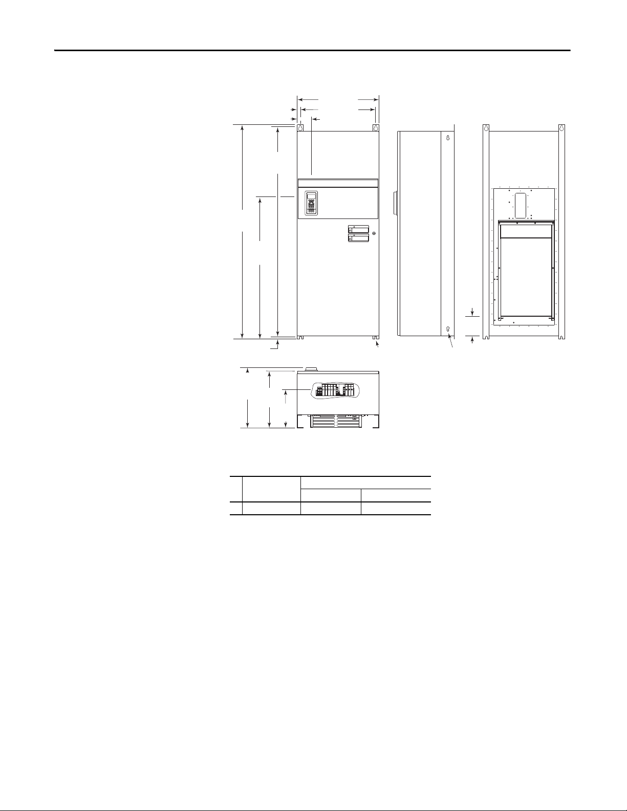
609.6 (24.00)
25.4 (1.00)
105.5 (4.15)
1574.8
(62.00)
1061.5
(41.79)
16.8 (0.66)
1543.0 ±1.5
(62.75 ±0.06)
450.7
(17.75)
Max.
425.5
(16.75)
287.0
(11.30)
558.8 (22.00)
REMOTE SOURCE(S) OF POWER.
DISCONNECT ALL SOURCES OF POWER
BEFORE OPENING THE DOOR.
DANGER
DANGER
ELECTRICAL SHOCK HAZARD FROM
ENERGY STORAGE CAPACITORS.
VERIFY LOW VOLTAGE DISCHARGE
BEFORE SERVICING.
SEE INSTRUCTION MANUAL.
13.5 (0.53) Dia. x 4
12.7 (0.50) Dia.
Lifting Holes
140.0
(5.51)
Air
Outlet
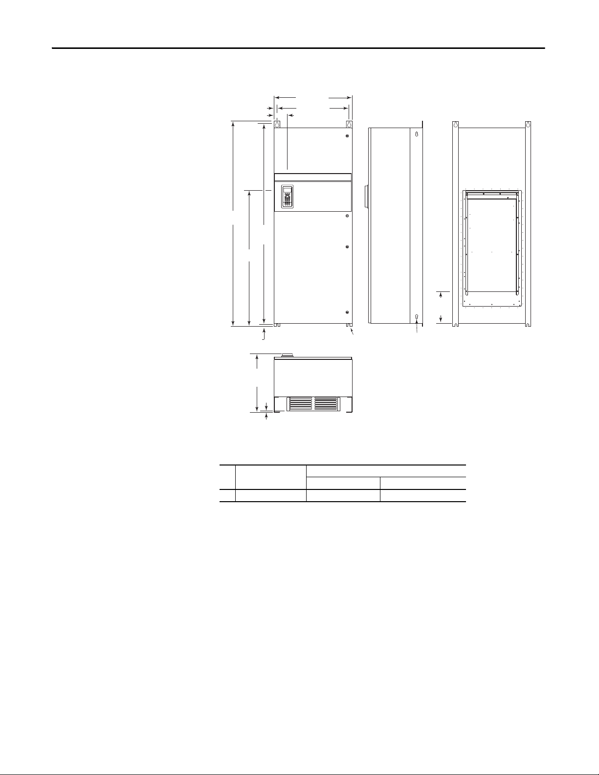
Mount with 0.50 in. UNC Grade 5 or higher screws
or
M12 Material Class 5.6 or higher screws.
Use flat washer with each fastener.
Dimensions are in millimeters and (inches)
Frame 5 – IP54, NEMA Type 12 Standalone (400…690V drives only)
Description
Frame
Approx. Weight
Drive Drive & Packaging
(1)
kg (lbs.)
5 Standalone 102.51 (226.0) 154.68 (341.0)
(1) Weights include HIM and Standard I/O.
14 Rockwell Automation Publication 20B-IN019E-EN-P - July 2013
Page 15
PowerFlex 700 Adjustable Frequency AC Drive – Frames 0…6
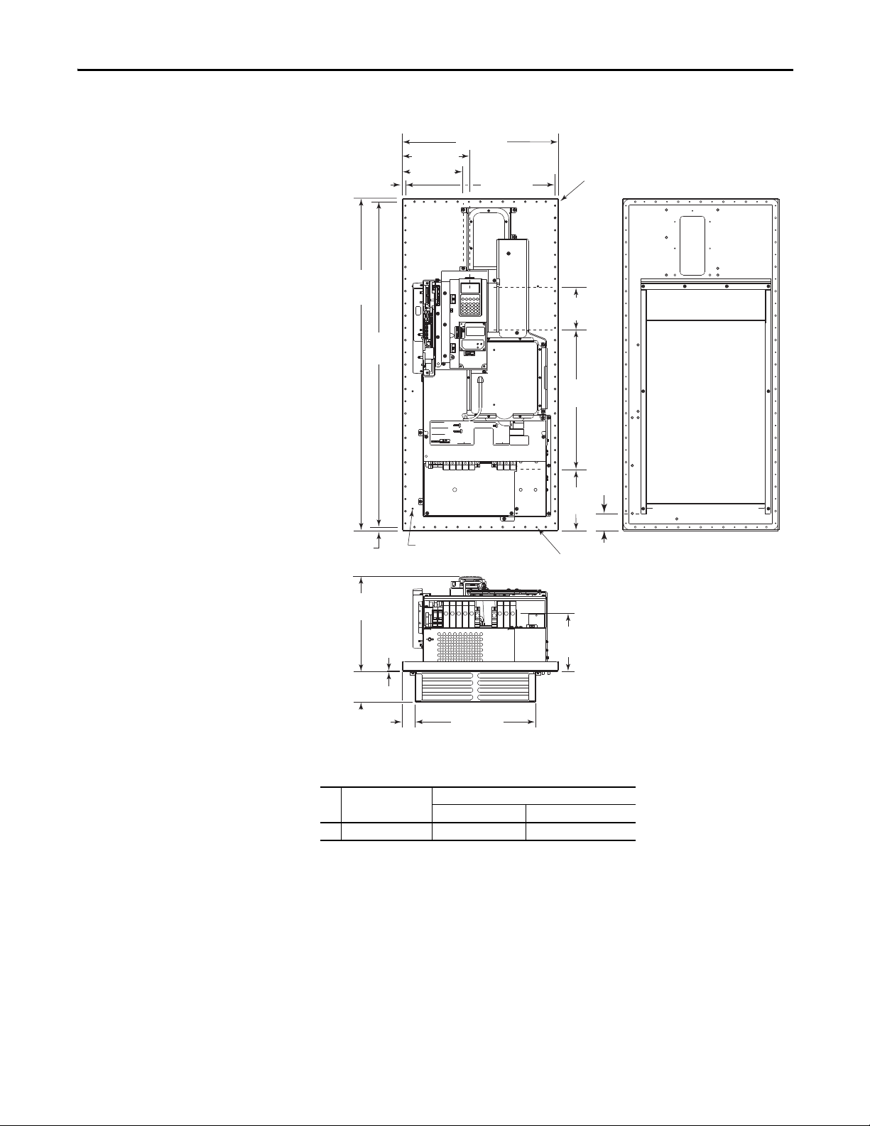
303.6
(11.95)
2.3 (0.09)
Compressed
Gasket
97.0
(3.82)
384.0 (15.12)
42.0 (1.65)
1061.0
(41.77)
1039.0
(40.91)
11.0 (0.43)
500.0 (19.69)
478.0 (18.82)
5.5 (0.22) Dia. x 40
12.7 (0.50) Dia. Lifting Holes x 4
Air
Outlet
11.0 (0.43)
53.2
(2.09)
USE 75 C CU WIRE ONLY
WIRE RANGE: 4-3/0 AWG (18-70 MM
2
)
TORQUE: 133 IN-LB (15 N-M)
STRIP LENGTH: 1.02 IN (26 MM)
POWER & DC TERMINAL RATINGS
WIRE RANGE: 14-1/0 AWG (2.5-50 MM2)
TORQUE: 32 IN-LB (3.6 N-M)
STRIP LENGTH: 0.67 IN (17 MM)
BRAKE TERMINAL RATINGS
WIRE RANGE: 6-1/0 AWG (18-35 MM2)
TORQUE: 44 IN-LB (5 N-M)
STRIP LENGTH: 0.83 IN (21 MM)
GROUND TERMINAL RATINGS (PE)
OUTPUT
INPUT AC
300 VDC EXT PWR SPLY TERM (PS+, PS-)
WIRE RANGE: 22-10 AWG (0.5-4 MM
2
)
TORQUE: 5.3 IN-LB (0.6 N-M)
STRIP LENGTH: 0.35 IN (9 MM)
DANGER
DANGER
RISK OF ELECTRIC
SHOCK AND DEATH
FIELD INSTALLED OPTIONS
6 MM HEX KEY6 MM HEX KEY
SHLD
SHLD
219.5 (8.64)
196.5 (7.74)
185.0
(7.30)
449.6
(17.74)
127.6
(5.02)
194.0
(7.60)
Ground
M5 PEM Nut
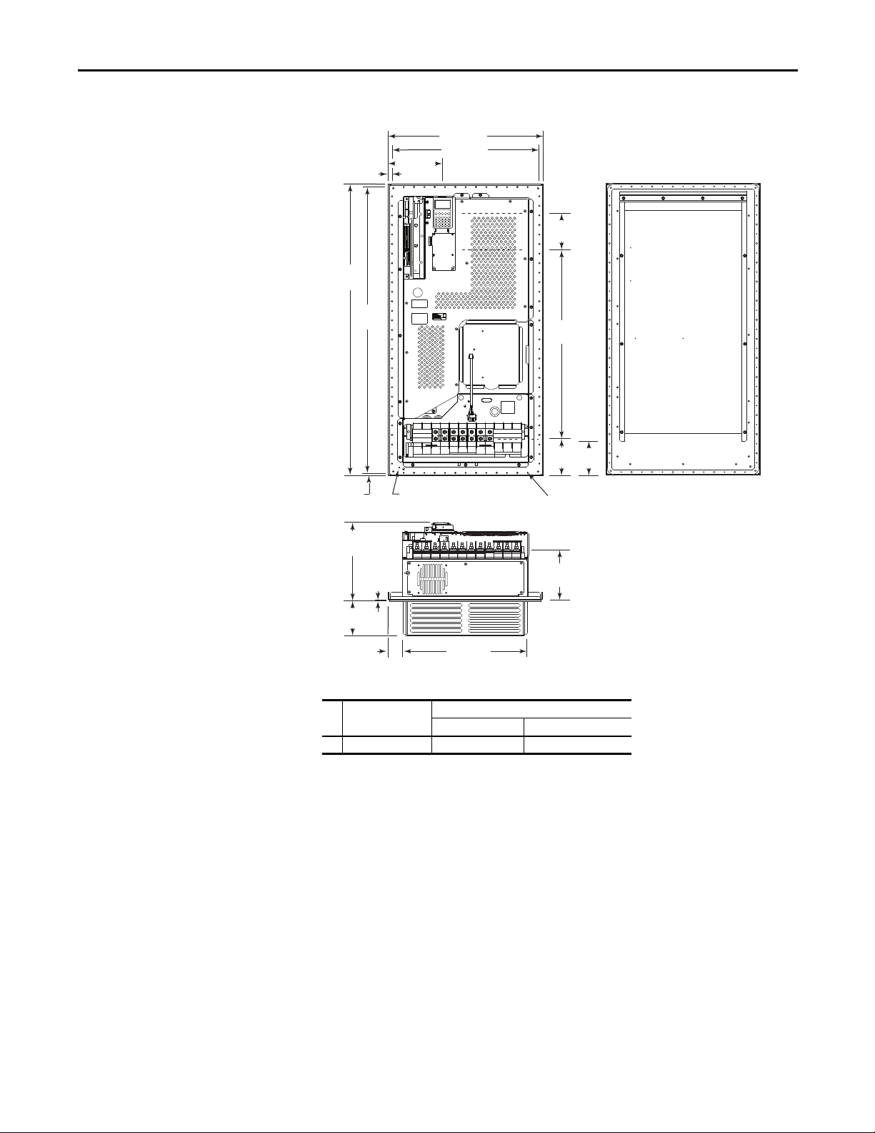
Dimensions are in millimeters
and (inches)
Frame 5 – IP54, NEMA Type 12 Flange Mount (400…690V drives only)
Description
Frame
5 Flange Mount 61.69 (136.0) 81.65 (180.0)
(1) Weights include HIM and Standard I/O.
Approx. Weight
Drive Drive & Packaging
(1)
kg (lbs. )
Rockwell Automation Publication 20B-IN019E-EN-P - July 2013 15
Page 16
PowerFlex 700 Adjustable Frequency AC Drive – Frames 0…6
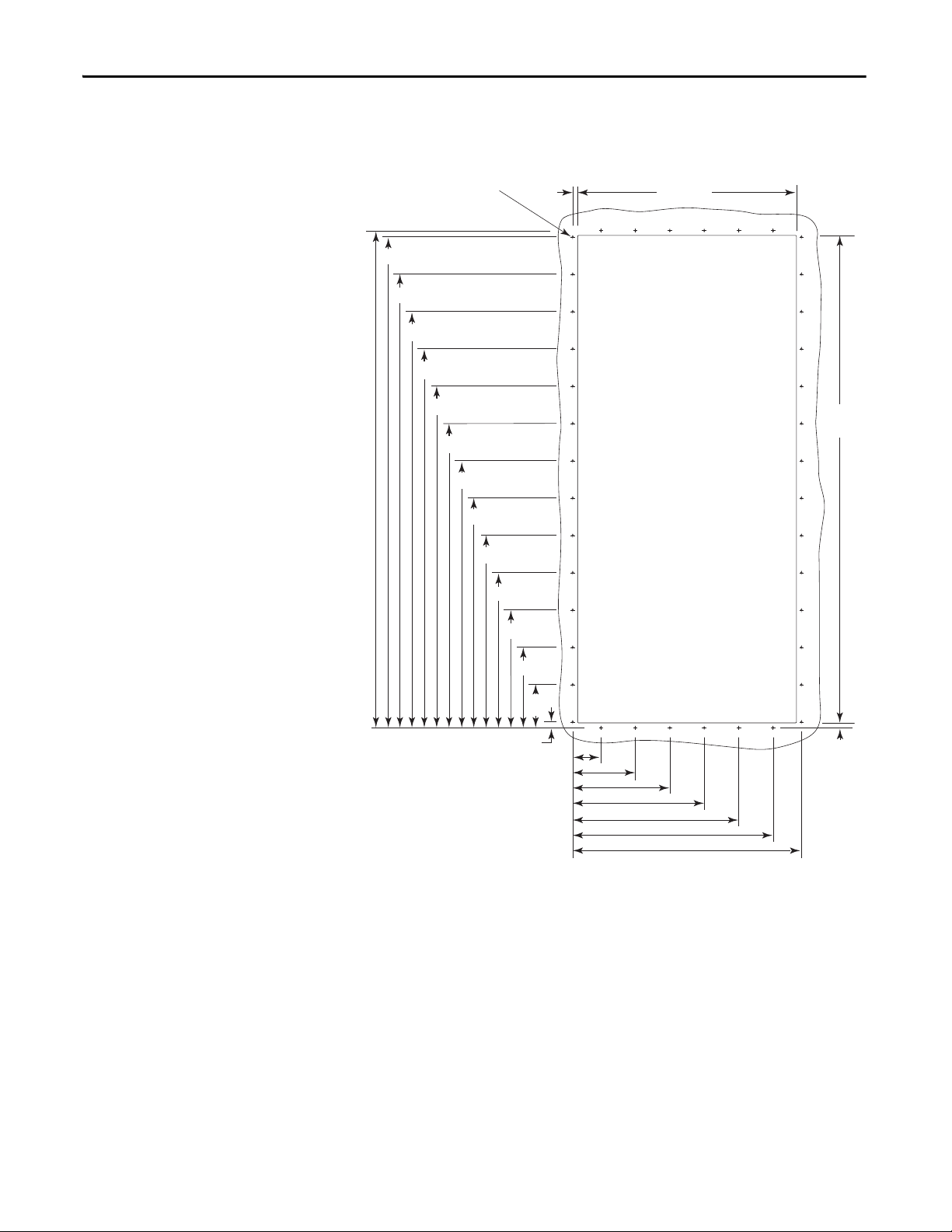
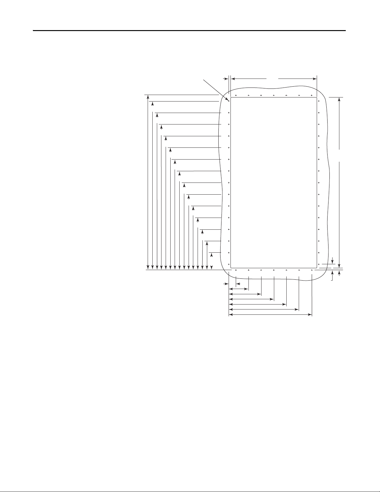
4.00 (0.157) Dia. x 40, minimum 14
GA. (1.9) steel mounting surface.
Deburr Pilot Holes and Dr ive Cutout.
Dimensions are in millimeters
and (inches)
Frame 5 – Flange Mount Cutout
1039.0
(40.91)
1026.5 (40.41)
948.5 (37.34)
870.5 (34.27)
792.5 (31.20)
714.5 (28.13)
636.5 (25.06)
558.5 (21.99)
480.5 (18.92)
402.5 (15.85)
324.5 (12.78)
(0.39)
246.5 (9.71)
10.0
458.0 (18.03)
Cutout
1019.0
(40.12)
168.5 (6.63)
(3.56)
12.5 (0.49)
131.0 (5.16)
203.0 (7.99)
275.0 (10.83)
347.0 (13.66)
419.0 (16.50)
478.0 (18.82)
90.5
59.0 (2.32)
10.0
(0.39)
16 Rockwell Automation Publication 20B-IN019E-EN-P - July 2013
Page 17
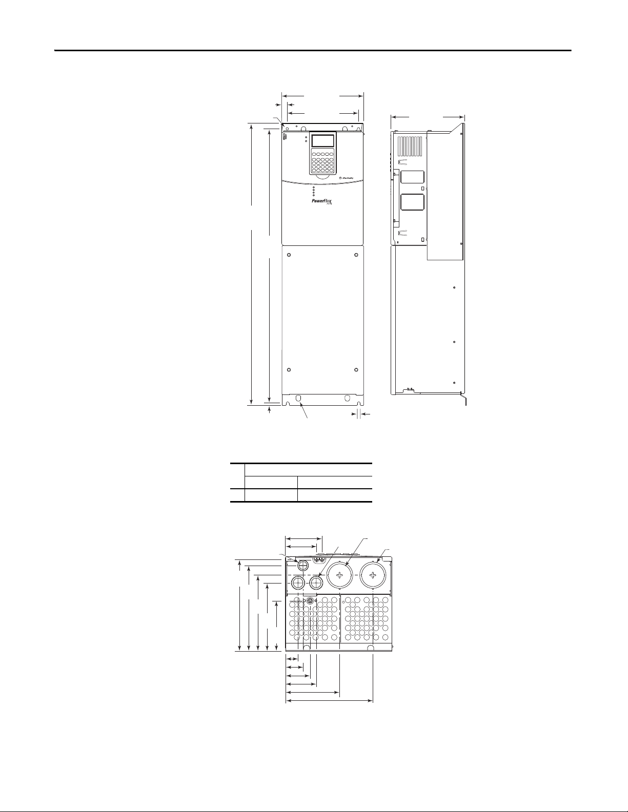
Frame 6 – IP20, NEMA/UL Type 1
825.0
(32.48)
13.5
(0.53)
126.3
(4.97)
8.5
(0.33)
850.0
(33.46)
Lifting Holes x 4
12.7 (0.50) Dia.
300.0 (11.81)
275.5 (10.85)
403.9 (15.90)
360.6 (14.20)
18.0 (0.71)
8.5 (0.33)
49.6 (1.95)
New Style Junction Box
Old Style Junction Box
Dimensions are in millimeters and (inches)
Junction Box can be removed if drive is mounted in a cabinet
PowerFlex 700 Adjustable Frequency AC Drive – Frames 0…6
Approx. Weight
Drive Drive & Packaging
Frame
(1)
kg (lbs.)
6 71.44 (157.5) 100.9 (222.0)
(1) Weights include HIM and Standard I/O. Add 13.60 kg (30.0 lbs.) for; 20BB260, 20BC260 and 20BD248 .
242.0
(9.53)
222.3
(8.75)
130.1 (5.12)
230.1 (9.06)
280.1 (11.03)
330.1 (13.00)
56.2 (2.21)
45.6 (1.80)
148.5
(5.85)
116.6
(4.59)
47.1 (1.85)
52.1 (2.05)
69.1 (2.72)
34.9 (1.37) Dia.
3 Places
62.7 (2.47) Dia.
3 Places
22.2 (0.87) Dia.
4 Places
Removable Junction Box
219.0
(8.62)
185.4
(7.30)
151.8
(5.98)
Rockwell Automation Publication 20B-IN019E-EN-P - July 2013 17
Page 18
PowerFlex 700 Adjustable Frequency AC Drive – Frames 0…6
Mount with 0.50 in. UNC Grade 5 or higher screws
or
M12 Material Class 5.6 or higher screws.
Use flat washer with each fastener
Dimensions are in millimeters and (inches)
Frame 6 – IP54, NEMA Type 12 Standalone (400…690V drives only)
1828.8
(72.00)
24.1 (0.90)
123.6 (4.90)
1279.5
(50.40)
16.8 (0.66)
487.8
(19.20) Max.
1795.2
(70.70)
711.3 (28.00)
663.1 (26.10)
13.5 (0.53) Dia. x 4
12.7 (0.50) Dia.
Lifting Holes
283.3
(11.20)
8.0
(0.30)
(1)
kg (lbs.)
Description
Frame
Approx. Weight
Drive Drive & Packaging
6 Standalone 176.90 (390.0) 229.07 (505.0)
(1) Weights include HIM and Standard I/O.
18 Rockwell Automation Publication 20B-IN019E-EN-P - July 2013
Page 19
PowerFlex 700 Adjustable Frequency AC Drive – Frames 0…6
UT1DC-DC+BR1BR2 VT2WT3RL1S
L2
OUTPUT
T
L3
PE PE
USE 75C COPPER WIRE ONLY, TORQUE 52 IN-LB (6 N-M)
22-12 AWG
5.3 IN-LB
(0.6 N-M)
PS+
PS-
WIRE STRIP
584.0 (23.00)
14.0 (0.60)
556.0 (21.90)
201.0 (7.90)
1100.0
(43.30)
1078.0
(42.40)
11.0 (0.43)
5.5 (0.22) Dia. x 44
127.3
(5.00)
763.3
(30.0)
105.8
(4.17)
137.2
(5.40)
294.7
(11.60)
2.4 (0.10)
Compressed
Gasket
131.6
(5.20)
468.2 (18.40)
57.9 (2.30)
193.7
(7.60)
Ground - M5 PEM Stud
Dimensions are in millimeters and
(inches)
Frame 6 – IP54, NEMA Type 12 Flange Mount (400…690V drives only)
Description
Frame
Approx. Weight
Drive Drive & Packaging
(1)
kg (lbs.)
6 Flange Mount 99.79 (220.0) 119.75 (264.0)
(1) Weights include HIM and Standard I/O.
Rockwell Automation Publication 20B-IN019E-EN-P - July 2013 19
Page 20
PowerFlex 700 Adjustable Frequency AC Drive – Frames 0…6
4.00 (0.157) Dia. x 44, minimum
14 GA. (1.9) steel mounting surface.
Deburr pilot holes and drive cutout.
Dimensions are in millimeters and (inches)
Frame 6 – Flange Mount Cutout
1078.0 (42.40)
1043.0 (41.10)
971.0 (38.20)
899.0 (35.40)
827.0 (32.60)
755.0 (29.70)
683.0 (26.90)
611.0 (24.10)
539.0 (21.20)
467.0 (18.40)
395.0 (15.60)
323.0 (12.70)
251.0 (9.90)
179.0
(7.00)
107.0
(4.20)
12.0
(0.50)
532.0
(20.90)
Cutout
1054.0
(41.5)
44.0 (1.70)
122.0 (4.80)
200.0 (7.90)
278.0 (10.90)
356.0 (14.00)
434.0 (17.10)
512.0 (20.20)
35.0
(1.40)
12.0
(0.50)
20 Rockwell Automation Publication 20B-IN019E-EN-P - July 2013
Page 21

PowerFlex 700 Adjustable Frequency AC Drive – Frames 0…6
Step 3: Wire the Drive – Power
Special Considerations
PowerFlex 700 drives are suitable for use on a circuit capable of delivering up to a
maximum of 200,000 rms symmetrical amperes.
ATT EN TI ON : To guard against personal injury and/or equipment damage
caused by improper fusing or circuit breaker selection, use only the
recommended line fuses/circuit breakers specified on page 33
If a system ground fault monitor (RCD) is to be used, only Type B (adjustable)
devices must be used to avoid nuisance tripping.
Unbalanced, Ungrounded, Resistive or B Phase Grounded Distribution Systems
If phase to ground voltage exceeds 125% of normal line to line voltage or the
supply system is ungrounded, refer to the Wiring and Grounding Guidelines for
Pulse Width Modulated (PWM) AC Drives, publication DRIVES-IN001
ATT EN TI ON : To guard against drive damage, PowerFlex 700 drives contain
protective MOVs and common mode capacitors that are referenced to ground.
These devices must be disconnected if the drive is not
grounded system. See page 43
for details.
.
.
installed on a solidly
Input Power Conditioning
Certain events on the power system supplying a drive can cause component
damage or shortened product life. These conditions are divided into 2 basic
categories:
1. All drives
• The power system has power factor correction capacitors switched in
and out of the system, either by the user or by the power company.
• The power source has intermittent voltage spikes in excess of 6000
volts. These spikes could be caused by other equipment on the line or by
events such as lightning strikes.
• The power source has frequent interruptions.
2. 5 Hp or Less Drives (in addition to “1
• The nearest supply transformer is larger than 100 kVA or the available
short circuit (fault) current is greater than 100,000A.
• The impedance in front of the drive is less than 0.5%.
If any or all of these conditions exist, it is recommended that the user install a
minimum amount of impedance between the drive and the source. This
impedance could come from the supply transformer itself, the cable between the
transformer and drive or an additional transformer or reactor. The impedance
can be calculated by using the information supplied in Wiring and Grounding
Guidelines for Pulse Width Modulated (PWM) AC Drives, publication
DRIVES-IN001
.
” above)
Rockwell Automation Publication 20B-IN019E-EN-P - July 2013 21
Page 22
PowerFlex 700 Adjustable Frequency AC Drive – Frames 0…6
ATT EN TI ON : National Codes and standards (NEC, VDE, BSI etc.) and local codes
outline provisions for safely installing electrical equipment. Installation must
comply with specifications regarding wire types, conductor sizes, branch circuit
protection and disconnect devices. Failure to do so can result in personal injury
and/or equipment damage.
EMC Compliance
Refer to page 7 for details.
CabIe Trays and Conduit
If cable trays or large conduits are to be used, refer to the guidelines presented in
the Wiring and Grounding Guidelines for Pulse Width Modulated (PWM) AC
Drives, publication DRIVES-IN001.
ATT EN TI ON : To avoid a possible shock hazard caused by induced voltages,
unused wires in the conduit must be grounded at both ends. For the same
reason, if a drive sharing a conduit is being serviced or installed, all drives using
this conduit must be disabled. This helps minimize the possible shock hazard
from “cross coupled” motor leads.
Motor Cable Lengths
Typically, motor lead lengths less than 30 meters (100 feet) are acceptable.
However, if your application dictates longer lengths, refer to the Wiring and
Grounding Guidelines for Pulse Width Modulated (PWM) AC Drives,
publication DRIVES-IN001
20B-TD001
.
or the PowerFlex 700 Technical Data, publication
Cable Types Acceptable for 200…600 Volt Installations
A variety of cable types are acceptable for drive installations. For many
installations, unshielded cable is adequate, provided it can be separated from
sensitive circuits. As an approximate guide, allow a spacing of 0.3 meters (1 foot)
for every 10 meters (32.8 feet) of length. In all cases, long parallel runs must be
avoided. Do not use cable with an insulation thickness less than or equal to 15
mils (0.4mm/0.015 in.). Use Copper wire only. Wire gauge requirements and
recommendations are based on 75 °C. Do not reduce wire gauge when using
higher temperature wire.
Unshielded Cable
THHN, THWN or similar wire is acceptable for drive installation in dry
environments provided adequate free air space and/or conduit fill rates limits are
provided. Do not use THHN or similarly coated wire in wet areas. Any wire
chosen must have a minimum insulation thickness of 15 Mils and must not have
large variations in insulation concentricity.
22 Rockwell Automation Publication 20B-IN019E-EN-P - July 2013
Page 23

PowerFlex 700 Adjustable Frequency AC Drive – Frames 0…6
Shielded/Armored Cable
Shielded cable contains all of the general benefits of multi-conductor cable with
the added benefit of a copper braided shield that can contain much of the noise
generated by a typical AC Drive. Strong consideration for shielded cable must be
given in installations with sensitive equipment such as weigh scales, capacitive
proximity switches and other devices that can be affected by electrical noise in the
distribution system. Applications with large numbers of drives in a similar
location, imposed EMC regulations or a high degree of communications/
networking are also good candidates for shielded cable.
Shielded cable can also help reduce shaft voltage and induced bearing currents for
some applications. In addition, the increased impedance of shielded cable can
help extend the distance that the motor is from the drive without the addition of
motor protective devices such as terminator networks. Refer to the Reflected
Wave topic in the Wiring and Grounding Guidelines for Pulse Width Modulated
(PWM) AC Drives, publication DRIVES-IN001
Consideration must be given to all of the general specifications dictated by the
environment of the installation, including temperature, flexibility, moisture
characteristics and chemical resistance. In addition, a braided shield must be
included and be specified by the cable manufacturer as having coverage of at least
75%. An additional foil shield can greatly improve noise containment.
.
A good example of recommended cable is Belden® 295xx (xx determines gauge).
This cable has four (4) XLPE insulated conductors with a 100% coverage foil and
an 85% coverage copper braided shield (with drain wire) surrounded by a PVC
jacket.
Other types of shielded cable are available, but the selection of these types can
limit the allowable cable length. Particularly, some of the newer cables bundle 4
conductors of THHN wire and wrap them tightly with a foil shield. This
construction can greatly increase the cable charging current required and reduce
the overall drive performance. Unless specified in the individual distance tables as
tested with the drive, these cables are not recommended and their performance
against the lead length limits supplied is not known. See Ta b l e 3
Table 3 - Recommended Shielded Wire
Location Rating/Type Description
Standard
(Option 1)
Standard
(Option 2)
Class I & II;
Division I &
II
600V, 90 °C (194 °F)
XHHW2/RHW-2 Anixter
B209500-B209507, Belden
29501-29507, or equivalent
Tray rated 600V, 90 °C
(194 °F) RHH/RHW-2 Anixter
OLF-7xxxxx or equivalent
Tray rated 600V, 90 °C
(194 °F) RHH/RHW-2 Anixter
7V-7xxxx-3G or equivalent
• Four tinned copper conductors with XLPE insulation.
• Copper braid/aluminum foil combination shield and tinned
copper drain wire.
•PVC jacket.
• Three tinned copper conductors with XLPE insulation.
• 5 mil single helical copper tape (25% overlap min.) with three
bare copper grounds in contact with shield.
•PVC jacket.
• Three bare copper conductors with XLPE insulation and
impervious corrugated continuously welded aluminum armor.
• Black sunlight resistant PVC jacket overall.
• Three copper grounds on #10 AWG and smaller.
.
Rockwell Automation Publication 20B-IN019E-EN-P - July 2013 23
Page 24
PowerFlex 700 Adjustable Frequency AC Drive – Frames 0…6
IMPORTANT
LINE
TYPE
SPARE 1
SPARE 2
3-PH 1-PH
JP1 JP2 JP3
1-PH 3-PH
LINE TYPE
333
AC Input
Precharge
Board
Single-Phase Input Power
The PowerFlex 700 drive is typically used with a three-phase input supply. Singlephase operation is possible with output current derated by 50% (at maximum
ambient temperature of 25 °C) of the three-phase ratings. Refer to tables 4
through 6
.
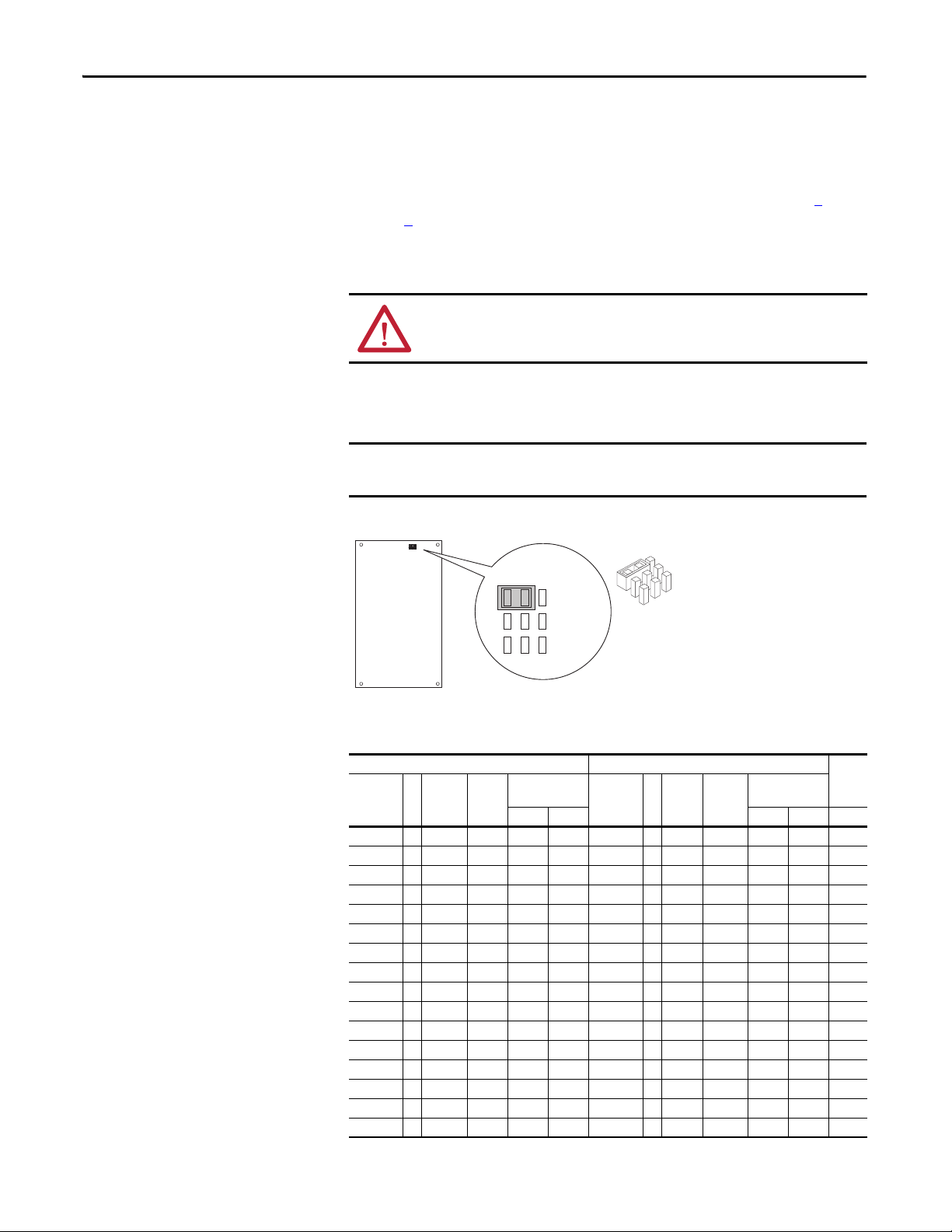
AC Input Phase Selection (Frames 5…6 Only)
ATT EN TI ON : To avoid a shock hazard, ensure that all power to the drive has
been removed before performing the following.
Moving the “Line Type” jumper on the Precharge Board (see below) allows single
or three-phase operation.
When selecting single-phase operation, input power must be applied to the
R (L1) and S (L2) terminals. This ensures that the fan is properly powered.
Typical Location - Phase Select Jumper
Table 4 - 208/240 Volt Single-Phase AC Input Ratings
240V Single-Phase AC Input 208V Single-Phase AC Input
Drive
Catalog
Number
20BB2P2 0 0.25 1.5 0-230 1.1 20BB2P2 0 0.25 1.7 0-200 1 .3 25
20BB4P2 0 0.5 2.8 0-230 2.1 20BB4P2 0 0.5 3.2 0-200 2.4 25
20BB6P8 1 1 5.1 0-230 3.4 20BB6P8 1 1 5.9 0-200 3.9 25
20BB9P6 1 1.5 7.2 0-230 4.8 20BB9P6 1 1.5 8.3 0-200 5.5 25
20BB015 1 2.5 11.9 0- 230 7.7 2 0BB015 1 2.5 13.6 0-200 8.8 25
20BB022 1 3.7 5 17.3 0-230 11 20BB022 1 3.75 19.9 0-200 12.7 25
20BB028 2 5 22.2 0-230 14 20BB028 2 5 25.7 0-200 16.1 25
20BB042 3 7.5 33.4 0- 230 21 20BB042 3 7.5 38.5 0-200 24.2 25
20BB052 3 10 41.3 0-230 26 20BB052 3 10 44.6 0-200 28 25
20BB070 4 12.5 5 5.6 0- 230 35 20BB070 4 12.5 62.3 0-200 3 9.1 25
20BB080 4 15 63.6 0-230 40 20BB080 4 15 73.3 0-200 46 25
20BB104 5 20 84.6 0-230 52 20BB104 5 20 97.9 0-200 60 25
24 Rockwell Automation Publication 20B-IN019E-EN-P - July 2013
20BB130 5 25 105.7 0-230 65 20BB130 5 25 106.1 0-200 65 25
20BB154 6 30 125.2 0-230 77 20BB154 6 30 144.4 0-200 88.5 25
20BB192 6 37.5 1 56.1 0-230 96 20BB192 6 37.5 180.3 0-200 110.5 25
20BB260 6 50 211.4 0-230 130 20BB260 6 50 212.1 0-200 130 25
Frame
Hp
Rating
Three-Phase
Output
Input
Amps
V AC Amps V AC Amps °C
Drive
Catalog
Number
Frame
Hp
Rating
Input
Amps
Three-Phase
Output
Tem p.
Page 25

PowerFlex 700 Adjustable Frequency AC Drive – Frames 0…6
Table 5 - 380…480 Volt Single-Phase AC Input Ratings
480V Single-Phase AC Input 380…400V Single-Phase AC Input
Drive
Catalog
Number
20BD1P1 0 0.25 0.7 0-460 0.6 20BC1P3 0 0.2 1 0-400 0.7 25
20BD2P1 0 0.5 1.4 0-460 1.1 20BC2P1 0 0.4 1.6 0-400 1.1 25
20BD3P4 0 1 2.3 0-460 1.7 20BC3P5 0 0.75 2.7 0-400 1.8 25
20BD5P0 0 1.5 3.4 0-460 2.5 20BC5P0 0 1.1 3.9 0-400 2.5 25
20BD8P0 0 2.5 6 0-460 4 20BC8P7 0 2 6.9 0-400 4.4 25
20BD011 0 3.75 8.2 0-460 5.5 20BC011 0 2.75 9.3 0-400 5.8 25
20BD014 1 5 10.9 0-460 7 20BC015 1 3.75 12.5 0-400 7.7 2 5
20BD022 1 7.5 17.3 0-460 11 20 BC022 1 5.5 17.8 0-400 11 25
20BD027 2 10 21.4 0-460 13.5 20BC030 2 7.5 24.6 0-400 15 25
20BD034 2 12.5 27 0-460 17 20BC037 2 9.25 30.3 0-400 18.5 25
20BD040 3 15 31.8 0-460 20 20BC043 3 11 35.2 0-400 21.5 2 5
20BD052 3 20 41.3 0-460 26 20BC056 3 15 45.9 0-400 28 25
20BD065 3 25 51.6 0-460 32.5 20BC072 3 18.5 59.7 0-400 36 25
20BD077 4 30 62.6 0-460 38.5 20BC085 4 22.5 70.5 0-400 42.5 25
20BD096 5 37.5 78.1 0-460 48 20BC105 5 27.5 87 0-400 52.5 25
20BD125 5 50 101.6 0-460 62.5 20BC125 5 27.5 103.6 0-400 62 .5 25
– – – – – – 20BC140 5 37.5 117.4 0-400 70 2 5
20BD156 6 62.5 126.8 0-460 78 20BC170 6 45 142.6 0-400 85 25
20BD180 6 75 146.4 0-460 90 20BC205 6 55 171.9 0-400 102.5 25
20BD248 6 100 201.6 0-460 124 20BC260 6 66 220.6 0-400 130 25
Frame
Hp
Rating
Three-Ph ase
Output
Input
Amps
V AC Amps V AC Amps °C
Drive
Catalog
Number
Frame
kW
Rating
Input
Amps
Three-Phase
Output
Temp .
Table 6 - 600…690 Volt Single-Phase AC Input Rating
600V Single-Phase AC Input 690V Single-Phase AC Input
Drive
Catalog
Number
20BE1P7 0 0.5 1.1 0-575 0.9 – – – – – – 25
20BE2P7 0 1 1.8 0-575 1.4 – – – – – – 25
20BE3P9 0 1.5 2.6 0-575 2 – – – – – – 25
20BE6P1 0 2.5 4.6 0-575 3.1 – – – – – – 25
20BE9P0 0 3.75 6.7 0-575 4.5 – – – – – – 25
20BE011 1 5 8.5 0-575 5.5 – – – – – – 25
20BE017 1 7.5 13.3 0-575 8.5 – – – – – – 25
20BE022 2 10 17.5 0-575 11 – – – – – – 25
20BE027 2 12.5 21.4 0-575 13.5 – – – – – – 25
20BE032 3 15 25.4 0-575 16 – – – – – – 25
20BE041 3 20 32.6 0-575 20.5 – – – – – – 25
20BE052 3 25 41.3 0-575 26 20BF052 5 22.5 43.1 0-690 26 25
20BE062 4 30 50.4 0-575 31 20BF060 5 27.5 49.9 0-690 30 25
20BE077 5 37.5 62.6 0-575 38.5 20BF082 5 37.5 68.4 0-690 41 25
20BE099 5 50 80.5 0-575 49.5 20BF098 5 45 82 0-690 49 25
20BE125 6 62.5 101.6 0-575 62.5 20BF119 6 55 100 0-690 59.5 25
20BE144 6 75 117.1 0-575 72 20BF142 6 66 120.2 0-690 71 25
Frame
Hp
Rating
Three-Phase
Output
Input
Amps
V AC Amps V AC Amps °C
Drive
Catalog
Number
Frame
kW
Rating
Input
Amps
Three-Phase
Output
Tem p.
Rockwell Automation Publication 20B-IN019E-EN-P - July 2013 25
Page 26

PowerFlex 700 Adjustable Frequency AC Drive – Frames 0…6
IMPORTANT
Secondary
115V
Fuse
3.5A, 250V
Red
Red
P1
P2
P3
Primary
Primary
400/480V
600/690V
Term i na l
P2
P3
P2
P3
Voltage
400
600
480
690
Selecting/Verifying Fan Voltage (Frames 5…6 Only)
ATT EN TI ON : To avoid a shock hazard, ensure that all power to the drive has
been removed before performing the following.
Frames 5 & 6 utilize a fan transformer to power the internal fan(s). This
transformer is sized specifically for the internal fan(s) and must not be used to
power other circuitry.
If your line voltage is different than the voltage class specified on the drive
nameplate, it can be necessary to change transformer taps as described. DC input
drives require user supplied 120 or 240V AC to power the cooling fans. The
power source is connected between “0 VAC” and the terminal corresponding to
your source voltage.
Table 7 - Frames 5…6 Fan Connections
Drive
Type E nclos ure
DC
IP00, NEMA/UL
Input
Typ e Op en
IP20, NEMA/UL
Typ e 1
IP54, NEMA/UL
Typ e 12
AC
IP00, NEMA/UL
Input
Typ e Op en
IP20, NEMA/UL
Typ e 1
IP54, NEMA/UL
Typ e 12
Rating
(120VAC)
100 VA
(Frame 5)
138 VA
(Frame 6)
100 VA
(Frame 5)
138 VA
(Frame 6)
100 VA
(Frame 5)
138 VA
(Frame 6)
100 VA
(Frame 5)
138 VA
(Frame 6)
No. of
Fans Connect at …
1 Power Terminal Block
Requires user supplied 120 or 240V AC. See page 29
locations and terminal designations.
1
1 N/A (Connected internally)
A transformer matches the input line voltage to the internal
fan voltage. If line voltage is different than the voltage class
specified on the drive nameplate, the transformer taps may
require changing.
1
The transformer is behind the Power Terminal Block. Access
is gained by releasing the terminal block from the rail and
removing the transformer cover plate.
1. Locate the small metal tab at the bottom of the end
terminal block.
2. Press the tab-in and pull the top of the block out. Repeat
for the next block if desired.
3. Remove the transformer cover plate.
4. Select the appropriate transformer tap.
5. Replace cover and terminal block.
for TB
26 Rockwell Automation Publication 20B-IN019E-EN-P - July 2013
Page 27

PowerFlex 700 Adjustable Frequency AC Drive – Frames 0…6
Auxiliary Control Power Supply
If desired, an auxiliary control power supply can be used with certain drives to
keep the control logic up when the main AC power is removed. An auxiliary
control power supply can only be used with:
• 400/480
and 600/690 Volt drives with Vector Control (15th position of
the catalog number string equals “C,” or “D”).
Using an auxiliary control power supply requires the use of some type of AC line
monitoring, as well as control of the Precharge Enable signal. Consult the factory
for additional guidance.
ATT EN TI ON : An Auxiliary Control Power Supply Must Not be used with any
PowerFlex 700 Standard Control drive or 200/240 Volt Vector Control drive.
Using the power supply with these drives causes equipment/component
damage.
Refer to page 29
Power supply must provide
UL Installation 300V DC, ±10% Frames 0…3: 40 W, 165 mA,
Non UL Installation 270…600V DC, ±10%
for terminal block locations.
Frame 5: 80 W, 90 mA
Rockwell Automation Publication 20B-IN019E-EN-P - July 2013 27
Page 28

PowerFlex 700 Adjustable Frequency AC Drive – Frames 0…6
Power Terminal Blocks
No. Name Frame Description
➊
Power
Terminal
Block
0…1 Input power and
motor connections
2 Input power and
motor connections
3 Input power and
motor connections
BR1, 2 terminals 10.0 mm
4 Input power and
motor connections
5
75Hp, 480V
100Hp, 600V
5
100 Hp
Input power, DC+,
DC–, BR1, 2, PE,
motor connections
Input power, DC+,
DC– and motor
BR1, 2, PE terminals 50.0 mm
6Input power, DC+,
DC–, BR1, 2, PE,
motor connections
(2)
Wire Size Range
Tor que
Maximum Minimum Maximum Recommended
2
4.0 mm
(12 AWG)
10.0 mm
(8 AWG)
25.0 mm
(3 AWG)
(8 AWG)
35.0 mm
(2 AWG)
50.0 mm
(1/0 AWG)
70.0 mm
(2/0 AWG)
(1/0 AWG)
150.0 mm
(300 MCM)
see Note
2
2
2
2
2
2
2
2
(3)
0.5 mm
(22 AWG)
0.8 mm
(18 AWG)
2.5 mm
(14 AWG)
0.8 mm
(18 AWG)
10.0 mm
(8 AWG)
4.0 mm
(12 AWG)
10.0 mm
(8 AWG)
4.0 mm
(12 AWG)
2.5 mm
(14 AWG)
2
2
2
2
2
2
2
2
2
1.7 N•m
(15 lb•in)
1.7 N•m
(15 lb•in)
3.6 N•m
(32 lb•in)
1.7 N•m
(15 lb•in)
4.0 N•m
(35 lb•in)
See Note
6.0 N•m
(52 lb•in)
0.8 N•m
(7 lb•in)
1.4 N•m
(12 lb•in)
1.8 N•m
(16 lb•in)
1.4 N•m
(12 lb•in)
4.0 N•m
(35 lb•in)
(4)
6.0 N•m
(52 lb•in)
➋
➌
➍
SHLD
Terminal
AUX
Terminal
Block
Fan
Terminal
0…6 Terminating point
— — 1.6 N•m
for wiring shields
0…4 Auxiliary Control
Vol tag e
(1)
5…6 4.0 mm
PS+, PS–
1.5 mm
(16 AWG)
(12 AWG)
5…6 User Supplied Fan
Vol tag e
4.0 mm
(12 AWG)
(14 lb•in)
2
0.2 mm
2
——
(24 AWG)
2
2
0.5 mm
(22 AWG)
0.5 mm
(22 AWG)
2
2
0.6 N•m
(5.3 lb•in)
0.6 N•m
(5.3 lb•in)
Block
(1) External control power: UL Installation-300V DC, ±10%, Non UL Installation-270…600V DC, ±10%
0…3 Frame - 40 W, 165 mA, 5 Frame - 80 W, 90 mA. Refer to the User Manual for fur ther information.
(2) Maximum/minimum wire sizes that the terminal block accepts - thes e are not recommend ations.
(3) If can be necessary to connect multiple wires in parallel to these terminals by using multiple lugs.
(4) Refer to the terminal block label inside the drive.
1.6 N•m
(14 lb•in)
0.6 N•m
(5.3 lb•in)
0.6 N•m
(5.3 lb•in)
28 Rockwell Automation Publication 20B-IN019E-EN-P - July 2013
Page 29

BR1 B
SHLD SHLD
V/T2 W/T3 PE R/L1 S/L2 T/L3
AUX IN+ AUX OUT–
Optional
Communications
Module
75C Cu Wire
6 AWG [10MM2] Max.
12 IN. LBS.
1.4 N-M
} TORQUE
WIRE
STRIP
CONTROL
POWER
BR1 BR2 DC+ DC- U/T1 V/T2 W/T3 R/L1 S/L2 T/L3
Optional
Communications
Module
PE B
PE A
75C Cu Wire
3 AWG [25MM2] Max.
16 IN. LBS.
1.8 N-M
} TORQUE
WIRE
STRIP
CONTROL
POWER
AUX IN
+ –
SHLD
SHLD
PE
75C Cu Wire
6 AWG [10MM2] Max.
BR1 BR2
12 IN. LBS.
1.4 N-M
} TORQUE
Optional
Communications
Module
L2L1T3T2T1 L3
INPUTOUTPUT
USE 75C
COPPER WIRE
ONLY
TORQUE
52 IN-LB
(6 N-M)
BR2
PS+
PS–
BR1 DC+ DC–
USE 75C COPPER WIRE ONLY, TORQUE 52 IN-LB (6 N-M)
22-10
AWG
5.3 IN-LB
(0.6 N-M)
WIRE STRIP
➊
➋
➊
➋
Frames 0…1
➌
➌
Frame 2
➋
➌
➊
Frame 6
➋
Frames 3…4
➌
➊
Frame 5
➋
➊
➌
➍
DC Input Drives
Only
Junction Box supplied on:
37 kW, 208V (50 Hp, 240V)
75 kW, 400V (100 Hp, 480V)
90kW, 690V (100 Hp, 600V)
Typical Terminal Block Location
DANGER
!
Use 75C Wire Only
#10-#14 AWG
Torque to 7 in-lbs
BR1
BR2
DC+
DC–
PE
U/T1
V/T2
W/T3
R/L1
S/L2
T/L3
PowerFlex 700 Adjustable Frequency AC Drive – Frames 0…6
/
PE
POWER TERMINAL RATINGS
WIRE RANGE: 14-1/0 AWG (2.5-35 MM2)
TORQUE: 32 IN-LB (3.6 N-M)
STRIP LENGTH: 0.67 IN (17 MM)
USE 75 C CU WIRE ONLY
GROUND TERMINAL RATINGS (PE)
WIRE RANGE: 6-1/0 AWG (16-35 MM
TORQUE: 44 IN-LB (5 N-M)
STRIP LENGTH: 0.83 IN (21 MM)
Optional
Communications
300 VDC EXT PWR SPLY TERM (PS+, PS-)
WIRE RANGE: 22-10 AWG (0.5-4 MM
TORQUE: 5.3 IN-LB (0.6 N-M)
STRIP LENGTH: 0.35 IN (9 MM)
17
2
)
21
Module
2
)
9
INPUT ACOUTPUT
For item number descriptions, see page 28.
Rockwell Automation Publication 20B-IN019E-EN-P - July 2013 29
Page 30

PowerFlex 700 Adjustable Frequency AC Drive – Frames 0…6
T
(L3)S(L2)R(L1)W(T3)V(T2)U(T1)
DC–DC+BR2BR1
T/L3S/L2R/L1PEPEW/T3
V/T2
U/T1
DC–
DC+
BR1*/
DC+
BR2*
PS–
PS+
240
VAC
120
VAC
0
VAC
PE PEW/T3V/T2U/T1DC–DC+
BR1*/
DC+
BR2*
PS–
PS+
➊
T/L3S/L2R/L1
PEPE
W/T3V/T2U/T1DC–DC+
BR1*/
DC+
BR2*
PS–
PS+
➊
USE 75 C
COPPER WIRE
ONLY
TORQUE
52 IN-LB
(6 N-M)
U
T1
DC–DC+BR1BR2
VT2W
T3
RL1S
L2
INPUTOUTPUT
T
L3
PE PE
USE 75 C COPPER WIRE ONLY, TORQUE 52 IN-LB (6 N-M)
22-10
AWG
5.3 IN-LB
(0.6 N-M)
WIRE STRIP
PS+
PS–
➌
➊
➋
Terminal Block Details
Frame Power Terminal Blocks
0…1 Notes:
2
BR1
BR2
DC+
DC–
PE
U (T1)
V (T2)
W (T3)
R (L1)
S (L2)
T (L3)
Shaded BR1 & BR2 Terminals are only present on
drives ordered with the Brake Option.
➊Precharge Resistor Fuse – DCT12-2
(DC input drives w/precharge only)
➋M8 Stud (All Terminals)
Max. Lug Width = 25.4 mm (1 in.)
➌M8 Stud (All Terminals)
Max. Lug Width = 31.8 mm (1.25 in.)
W
(T3)V(T2)U(T1)
T
PEDC–DC+BR2BR1
(L3)S(L2)R(L1)
3…4
AC Input (Ratings are Normal Duty) DC Input (Ratings are Normal Duty)
5 240V, 40 Hp 480V, 75 Hp 690V, 45…90 kW
400V, 55 kW 600V, 75 Hp
240V, 50 Hp 480V, 100 Hp
400V, 75 kW 600V, 100 Hp
240V, 40 Hp 480V, 75 Hp 690V, 45…90 kW
400V, 55 kW 600V, 75 Hp
240V, 50 Hp 480V, 100 Hp
400V, 75 kW 600V, 100 Hp
BR1*/
DC+
BR2*
PS–
PS+
6 125…200 Hp 125…200 Hp
240
0
VAC
VAC
W/T3V/T2U/T1DC–DC+
PE
PE
120
VAC
30 Rockwell Automation Publication 20B-IN019E-EN-P - July 2013
PS+
PS–
22-10
AWG
5.3 IN-LB
WIRE STRIP
(0.6 N-M)
USE 75 C COPPER WIRE ONLY, TORQUE 52 IN-LB (6 N-M)
USE 75 C
COPPER WIRE
ONLY
U
TORQUE
T1
52 IN-LB
(6 N-M)
VT2W
OUTPUT
DC–DC+BR1BR2
0 VAC
120 VAC
240 VAC
22-10 AWG
PE PE
5.3 IN-LB
T3
(0.6 N-M)
FAN
1-PHASE
INPUT
Page 31

Terminal Description Notes
IMPORTANT
BR1
BR2
DC+
DC–
PE PE Ground Refer to page 29
PS+
PS–
U
V
W
R
S
T
DC Brake (+)
DC Brake (–)
DC Bus (+)
DC Bus (–)
AUX (+)
AUX (–)
Motor Ground Refer to page 29
U (T1)
V (T2)
W (T3)
R (L1)
S (L2)
T (L3)
DB Resistor Connection - Important: Only one DB resistor can be used with Frames
0…3. Connecting an internal & external resistor could cause damage.
Twisted pa ir wiring must be use d from thes e terminals to the resistor. Wiring must be
routed separately from other cabling.
DC Input/Brake Connections (chopper and resistor).
Auxiliary Control Voltage
To M ot or /Lo ad
AC Line Input Power
Three-P hase = R, S & T
Single-Phase = R & S Only (refer to User Manual for details)
PowerFlex 700 Adjustable Frequency AC Drive – Frames 0…6
for location on Frame 3 drives
for location on Frame 3 drives
Power and Ground Wiring
The drive Safety Ground - PE must be connected to system ground. Ground
impedance must conform to the requirements of national and local industrial
safety regulations and/or electrical codes. Periodically check the integrity of all
ground connections.
For installations within a cabinet, a single safety ground point or ground bus bar
connected directly to building steel must be used. All circuits including the AC
input ground conductor must be grounded independently and directly to this
point/bar.
Typical Grounding
SHLD
U (T1)
V (T2)
W (T3)
Safety Ground - PE
R (L1)
S (L2)
T (L3)
PE
This is the safety ground for the drive that is required by code. This point must be
connected to adjacent building steel (girder, joist), a floor ground rod or bus bar
(see above). Grounding points must comply with national and local industrial
safety regulations and/or electrical codes.
Do Not discard or replace grounding hardware.
Rockwell Automation Publication 20B-IN019E-EN-P - July 2013 31
Page 32

PowerFlex 700 Adjustable Frequency AC Drive – Frames 0…6
Shield Termination
Shield termination at “SHLD” provides a grounding point for the motor cable
shield. The motor cable shield must be connected to this terminal on the drive
(drive end) and the motor frame (motor end). A shield terminating cable gland
can also be used.
When shielded cable is used for control and signal wiring, the shield must be
grounded at the source end only, not at the drive end.
RFI Filter Grounding
Using an optional RFI filter can result in relatively high ground leakage currents.
Therefore, the filter must only be used in installations with grounded AC
supply systems and be permanently installed and solidly grounded (bonded)
to the building power distribution ground. Ensure that the incoming supply
neutral is solidly connected (bonded) to the same building power distribution
ground. Grounding must not rely on flexible cables and must not include any
form of plug or socket that permits inadvertent disconnection. Some local codes
can require redundant ground connections. Periodically check the integrity of all
connections. Refer to the instructions supplied with the filter.
Motor Overload Protection
Drives with Standard Control
PowerFlex 700 drives with standard control, identified by an N, A, or B in
position 15 of the catalog number, only provide Class 10 motor overload
protection according to NEC article 430. They do not provide speed sensitive
overload protection, thermal memory retention and motor over-temperature
sensing according to NEC article 430.126 (A) (2). If such protection is needed in
the end-use product, it must be provided by additional means.
Drives with Vector Control
PowerFlex 700 drives with vector control, identified by a C or D in position 15 of
the catalog number, provide class 10 motor overload protection according to
NEC article 430 and motor over-temperature protection according to NEC
article 430.126 (A) (2). UL 508C File E59272.
32 Rockwell Automation Publication 20B-IN019E-EN-P - July 2013
Page 33

PowerFlex 700 Adjustable Frequency AC Drive – Frames 0…6
Drive, Fuse & Circuit Breaker Ratings
The PowerFlex 700 can be installed with input fuses or an input circuit breaker.
National and local industrial safety regulations and/or electrical codes can
determine additional requirements for these installations.
ATT EN TI ON : The PowerFlex 700 does not provide branch short circuit
protection. Specifications for the recommended fuse or circuit breaker to
provide protection against short circuits are provided on pages 34
The tables on the following pages provide recommended AC line input fuse and
circuit breaker information. See Fusing and Circuit Breakers below for UL and
IEC requirements. Sizes listed are the recommended sizes based on 40 °C (104
°F) and the U.S. NEC. Other country, state, or local codes can require different
ratings. Tables with DC link fuse recommendations for DC input drives are also
provided.
Fusi ng
through 41.
The recommended fuse types are listed below. If available current ratings do not
match those listed in the tables provided, choose the next higher fuse rating.
• IEC – BS88 (British Standard) Parts 1 & 2, EN60269-1, Parts 1 & 2
(1)
,
type gG or equivalent must be used.
• UL - UL Class CC, T, RK1 or J must be used.
Circuit Breakers
The “non-fuse” listings in the following tables include inverse time circuit
breakers, instantaneous trip circuit breakers (motor circuit protectors) and 140M
self-protected combination motor controllers. If one of these is chosen as the
desired protection method, the following requirements apply:
• IEC – Both types of circuit breakers and 140M self-protected
combination motor controllers are acceptable for IEC installations.
• UL - Only inverse time circuit breakers and the specified 140M selfprotected combination motor controllers are acceptable for UL
installations.
(1) Typical designations include, but may not be limited to the following; Parts 1 & 2: AC, AD, BC, BD, CD, DD, ED, EFS, EF, FF, FG, GF, GG,
GH.
Rockwell Automation Publication 20B-IN019E-EN-P - July 2013 33
Page 34

PowerFlex 700 Adjustable Frequency AC Drive – Frames 0…6
208 Volt AC Input Protection Devices
Drive
Catalog
Number
Hp
Rating
ND HD kHz °C Amps kVA Cont. 1 Min. 3 Sec. Min.
Frame
PWM
Freq.
Tem p.
Input
(11)
Ratings Output Amps
Dual Element
Time Delay
Fuse
(1)
Max.
Non-Time Delay
Fuse
(2)
(1)
Min.
Max.
(2)
Circuit
Breaker
(3)
Max.
(8)
Motor
Circuit
Protector
(8)
Max.
140M Motor Protector with Adjustable Current
(4)
(5)(6)
Range
Available Catalog Numbers -
(7)
140…
Min. Enclosure
Vol. ( in.
20BB2P2 0 0.5 0.33 4 50 1.9 0.7 2.5 2.8 3.8 3 6 3 10 15 3 M-C2E-B25 M-D8E-B25 – 7269
20BB4P2 0 1 0.75 4 50 3.7 1.3 4.8 5.6 7 6 10 6 17.5 15 7 M-C2E-B63 M-D8E-B63 – 7269
20BB6P8 1 2 1.5 4 50 6.8 2.4 7.8 10.4 13 .8 10 15 10 30 30 15 M-C2E-C10 M -D8E-C10 M-F8E-C10 7269
20BB9P6 1 3 2 4 50 9.5 3.4 11 12.1 17 12 20 12 40 40 15 M-C2E- C16 M-D8E-C16 M-F8E-C16 7269
20BB015 1 5 3 4 50 15.7 5.7 17.5 19.3 26.3 20 35 20 70 70 30 M-C2E- C20 M-D8E-C20 M-F8E-C20 7269
20BB022 1 7.5 5 4 50 23 8.3 25.3 27.8 38 30 50 30 100 100 30 – M-D8E-C25 M-F8E-C25 7269
20BB028 2 10 7.5 4 50 29.6 10.7 32.2 38 50.6 40 70 40 125 125 50 – – M-F8E-C32 7269
20BB042 3 15 10 4 50 44.5 16 48.3 53.1 72.5 60 100 60 175 175 70 – – M-F8E-C45 136 30
20BB052 3 20 15 4 50 51.5 17.1 56 64 86 80 125 80 200 200 100 – – – –
20BB070 4 25 20 4 50 72 25.9 78.2 93 124 90 175 90 300 300 100 – – – –
20BB080 4 30 25 4 50 84.7 30.5 92 117 156 110 200 110 350 350 150 – – – –
20BB104
5 40 – 4 50 113 40.7 120 132 175 150 250 150 475 350 150 – – – –
(12)
20BB130
(12)
20BB154
(12)
20BB192
(12)
20BB260
(12)
See page 38
– 30 4 50 84.7 30.5 92 138 175 125 200 125 350 300 150 – – – –
5 50 – 4 50 141 44.1 130 14 3 175 175 275 175 500 375 250 – – – –
– 40 4 50 113 35.3 104 156 175 125 225 125 400 300 150 – – – –
6 60 – 4 50 167 60.1 177 19 5 266 225 350 225 500 500 250 – – – –
– 50 4 50 141 50.9 150 225 300 200 300 200 500 450 250 – – – –
6 75 – 4 50 208 75 221 243 308 300 450 300 600 600 400 – – – –
– 60 4 50 167 60.1 177 266 308 225 350 225 500 500 250 – – – –
6 100 – 2 45 255 91.9 260 286 390 300 575 300 750 750 400 – – – –
– 75 2 50 199 71.7 205 305 410 225 450 225 600 600 400 – – – –
for notes.
3)(14)
240 Volt AC Input Protection Devices
Circuit
PWM
Tem p.
Drive
Catalog
Number
Hp Rating
ND HD kHz °C Amps kVA Cont. 1 Min. 3 Sec. Min.
Frame
Freq.
(11)
Ratings Output Amps
Input
Dual Element
Time Delay Fuse
(1)
Max.
Non-Time Delay
Fuse
(2)
(1)
Min.
Max.
(2)
20BB2P2 0 0.5 0.33 4 50 1.7 0.7 2.2 2.4 3.3 3 6 3 10 15 3 M-C2E-B25 M-D8E-B25 – 7 269
20BB4P2 0 1 0.75 4 50 3.3 1.4 4.2 4.8 6.4 5 8 5 15 15 7 M-C2E-B63 M-D8E-B63 – 7 269
20BB6P8 1 2 1.5 4 50 5 .9 2.4 6.8 9 12 10 15 10 25 25 15 M-C2E-C10 M-D 8E-C10 M-F8E- C10 7269
20BB9P6 1 3 2 4 50 8.3 3.4 9.6 10.6 14.4 12 20 12 35 35 15 M-C2E-C10 M-D8E-C10 M-F8E-C10 7269
20BB015 1 5 3 4 50 13.7 5.7 15.3 16.8 23 20 30 20 60 60 30 M-C2E-C16 M-D8E-C16 M-F8E-C16 7269
20BB022 1 7.5 5 4 50 19.9 8.3 22 24.2 33 25 50 25 80 8 0 30 – M-D8E-C25 M-F8E-C25 7269
20BB028 2 10 7.5 4 50 2 5.7 10.7 28 33 44 35 60 35 100 100 50 – – M-F8E-C32 7269
20BB042 3 15 10 4 50 38.5 16 42 46.2 63 50 90 5 0 150 150 50 – – M-F8E-C45 13630
20BB052 3 20 15 4 50 47.7 19.8 52 63 80 60 100 60 200 200 100 – – – –
20BB070 4 25 20 4 50 64.2 26.7 70 78 105 90 150 90 2 75 275 100 – – – –
20BB080 4 30 25 4 50 73.2 30.5 80 105 140 100 180 100 300 300 100 – – – –
20BB104
5 40 – 4 50 98 40.6 104 115 175 125 225 125 400 300 150 – – – –
(12)
20BB130
(12)
20BB154
(12)
20BB192
(12)
20BB260
(12)
See page 38
– 30 4 50 73 30.5 80 120 160 100 175 100 300 300 100 – – – –
5 50 – 4 50 122 50.7 130 143 175 175 275 175 500 375 250 – – – –
– 40 4 50 98 40.6 104 156 175 125 225 125 400 300 150 – – – –
6 60 – 4 50 145 60.1 154 169 231 200 300 200 600 450 250 – – – –
– 50 4 50 122 50.7 130 195 260 175 275 175 500 375 250 – – – –
6 75 – 4 50 180 74.9 192 211 288 225 400 225 600 575 250 – – – –
– 60 4 50 145 60.1 154 231 308 200 300 200 600 450 250 – – – –
6 100 – 2 45 233 96.7 260 286 390 300 575 300 750 750 300 – – – –
– 75 2 50 169 70.1 205 305 410 225 450 225 600 600 250 – – – –
for notes.
Breaker
(3)
Max.
(8)
Motor
Circuit
Protector
(8)
Max.
140M Motor Protector with Adjustable Current
(4)
(5)(6)
Range
Available Catalog Numbers -
(7)
140…
Min. Enclosure
Vol. (in .
3)(14)
34 Rockwell Automation Publication 20B-IN019E-EN-P - July 2013
Page 35

Drive
kW
Rating
PWM
Freq. Temp.
Catalog
Number
ND HD kHz °C Amps kVA Cont. 1 Min. 3 Sec. Min.
Frame
20BC1P3 0 0.37 0.25 4 50
20BC2P1 0 0.75 0.55 4 50
20BC3P5 0 1.5 0.75 4 50
20BC5P0 0 2.2 1.5 4 50
20BC8P7 0 4 2.2 4 50
20BC011 0 5.5 4 4 50
20BC015 1 7.5 5.5 4 50
20BC022 1 11 7.5 4 50
20BC030 2 15 11 4 50
20BC037 2 18.5 15 4 50
20BC043 3 22 18.5 4 50
20BC056 3 30 22 4 50
20BC072 3 37 30 4 50
445 – 4 45
20BC085
(12)
20BC105
(12)
20BC125
(12)
20BC140
(12)
20BC170
(12)
20BC205
(12)
20BC260
(12)
See page 38
–374 45
555 – 4 50
–454 50
555 – 4 50
–454 50
575 – 4 40
–554 40
690 – 4 50
–754 50
6110– 4 40
–904 40
6132– 2 45
– 110 2 50
for notes.
PowerFlex 700 Adjustable Frequency AC Drive – Frames 0…6
400 Volt AC Input Protection Devices
Motor
Circuit
Input
Ratings Output Amps
(11)
1.1 0.77 1.3 1.4 1.9 3 3 3 6 15 3 M- C2E-B16 – – 7269
(11)
1.8 1.3 2.1 2.4 3.2 3 6 3 8 15 3 M-C2E-B25 M-D8E-B25 – 7269
(11)
3.2 2.2 3.5 4.5 6 6 7 6 12 15 7 M-C2E-B40 M-D8E-B40 – 7269
(11)
4.6 3.2 5 5.5 7.5 6 10 6 20 20 7 M-C2E-B63 M-D8E-B63 – 7269
(11)
7.9 5.5 8.7 9.9 13.2 15 17.5 15 30 30 15 M-C2E-C10 M-D8E-C10 M-F8E-C10 7269
(11)
10.8 7.5 11.5 13 17.4 15 25 15 45 45 15 M-C2E-C16 M-D8E-C16 M-F8E-C16 7269
(11)
14.4 10 15.4 17.2 23.1 20 30 20 60 60 20 M-C2E-C20 M-D8E-C20 M-F8E-C20 7269
(11)
20.6 14.3 22 24.2 33 30 45 30 80 80 30 – M-D8E-C25 M-F8E-C25 7269
(11)
28.4 19.7 30 33 45 35 60 35 120 120 50 – – M-F8E-C32 7269
(11)
35 24.3 37 45 60 45 80 45 125 125 50 – – M-F8E-C45 7269
(11)
40.7 28.2 43 56 74 60 90 60 150 150 60 – – – –
(11)
53 36.7 56 64 86 70 125 70 200 200 100 – – – –
(10)(11)
68.9 47.8 72 84 112 90 150 90 250 250 100 – – – –
(11)
81.4 56.4 85 94 128 110 200 110 300 300 150 – – – –
(11)
68.9 47.8 72 108 144 90 175 90 275 300 100 – – – –
(9)
100.5 69.6 105 116 158 125 225 125 400 300 150 – – – –
(9)
81.4 56.4 85 128 170 110 175 110 300 300 150 – – – –
(9)
121.1 83.9 125 138 163 150 275 150 500 375 250 – – – –
(9)
91.9 63.7 96 144 168 125 200 125 375 375 150 – – – –
(9)
136 93.9 140 154 190 200 300 200 400 400 250 – – – –
(9)
101 69.6 105 157 190 150 225 150 300 300 150 – – – –
(9)
164 126 170 187 255 250 375 250 600 500 250 – – – –
(9)
136 103 140 210 280 200 300 200 550 400 250 – – – –
(9)
199 148 205 220 289 250 450 250 600 600 400 – – – –
(9)
164 126 170 255 313 250 375 250 600 500 250 – – – –
(9)
255 177 260 286 390 350 550 350 750 750 400 – – – –
(9)
199 138 205 308 410 250 450 250 600 600 400 – – – –
Dual Element
Time Delay Fuse
(1)
Max.
Non-Time Delay
Fuse
(2)
(1)
Min.
Max.
(2)
Breaker
(3)
Max.
(8)
Circuit
Protector
(4)
(8)
Max.
140M Motor Protector with Adjustable Current
(5)(6)
Range
Available Catalog Numbers -
(7)
140…
Min. Enclosure
3)(14)
Vol. (in .
Rockwell Automation Publication 20B-IN019E-EN-P - July 2013 35
Page 36

PowerFlex 700 Adjustable Frequency AC Drive – Frames 0…6
Hp
Drive
Rating
Catalog
Number
ND HD kHz °C Amps kVA Cont. 1 Min. 3 Sec. Min.
Frame
20BD1P1 0 0.5 0.33 4 50
20BD2P1 0 1 0.75 4 50
20BD3P4 0 2 1.5 4 50
20BD5P0 0 3 2 4 50
20BD8P0 0 5 3 4 50
20BD011 0 7.5 5 4 50
20BD014 1 10 7.5 4 50
20BD022 1 15 10 4 50
20BD027 2 20 15 4 50
20BD034 2 25 20 4 50
20BD040 3 30 25 4 50
20BD052 3 40 30 4 50
20BD065 3 50 40 4 50
460 – 4 50
20BD077
(12)
20BD096
(12)
20BD125
(12)
20BD156
(12)
20BD180
(12)
20BD248
(12)
See page 38
–504 50
575 – 4 50
–604 50
5100– 4 50
–754 50
6125– 4 50
– 100 4 50
6150– 4 50
– 125 4 50
6200– 2 45
– 150 2 50
for notes.
PWM
Freq. Temp.
(11)
(11)
(11)
(11)
(11)
(11)
(11)
(11)
(11)
(11)
(11)
(11)
(11)
(11)
(11)
(9)
(9)
(9)
(9)
(9)
(9)
(9)
(9)
(9)
(9)
Input
Ratings Output Amps
0.9 0.7 1.1 1.2 1.6 3 3 3 6 1 5 3 M-C2E-B16 – – 7269
1.6 1.4 2.1 2.4 3.2 3 6 3 8 1 5 3 M-C2E-B25 – – 7269
2.6 2.2 3.4 4.5 6 4 8 4 12 15 7 M-C2E-B40 M-D8E-B40 – 7269
3.9 3.2 5 5.5 7.5 6 10 6 20 20 7 M- C2E-B63 M-D8E-B63 – 7 269
6.9 5.7 8 8.8 12 10 15 10 30 30 15 M-C2E-C10 M-D8E-C10 M-F8E-C10 7269
9.5 7.9 11 12.1 16.5 15 20 15 40 40 15 M-C2E-C16 M-D8E-C16 M-F8E-C16 7269
12.5 10.4 14 16.5 22 17.5 30 17.5 50 50 20 M-C2E-C16 M-D8E-C16 M-F8E-C16 7269
19.9 16.6 22 24.2 33 25 50 25 80 80 30 – M-D8E-C25 M-F8E-C25 7269
24.8 20.6 27 33 44 35 60 35 10 0 100 50 – – M-F8E- C32 7269
31.2 25.9 34 40.5 54 40 70 40 125 125 50 – – M-F8E-C45 7 269
36.7 30.5 40 51 68 50 90 50 15 0 150 50 – – M-F8E- C45 13630
47.7 39.7 52 60 80 60 110 60 200 200 70 – – – –
59.6 49.6 65 78 104 80 125 80 250 250 100 – – – –
72.3 60.1 77 85 116 100 170 100 300 300 100 – – – –
59.6 49.6 65 98 130 80 125 80 250 250 100 – – – –
90.1 74.9 96 106 144 125 200 125 350 350 125 – – – –
72.3 60.1 77 116 154 100 170 100 300 300 100 – – – –
117 97.6 12 5 138 163 150 250 150 50 0 375 150 – – – –
90.1 74.9 96 144 168 125 200 125 350 350 125 – – – –
147 122 156 172 234 200 350 200 600 450 250 – – – –
131 109 125 188 250 175 250 175 500 375 250 – – – –
169 141 180 198 270 225 400 225 600 500 250 – – – –
147 122 156 234 312 200 350 200 600 450 250 – – – –
233 194 248 273 372 300 550 300 700 700 400 – – – –
169 141 180 270 360 225 400 225 600 500 250 – – – –
480 Volt AC Input Protection Devices
Dual Element
Time Delay Fuse
(1)
Max.
Non-Time Delay
Fuse
(2)
(1)
Min.
Max.
(2)
Circuit
Breaker
(3)
Max.
(8)
Motor
Circuit
Protector
(4)
(8)
Max.
140M Motor Protector with Adjustable Current
(5)(6)
Range
Available Catalog Numbers -
(7)
140…
Min. Enclosure
3)(14)
Vol. (in .
36 Rockwell Automation Publication 20B-IN019E-EN-P - July 2013
Page 37

PowerFlex 700 Adjustable Frequency AC Drive – Frames 0…6
Max.
(2)
(13)
Circuit
Breaker
(3)
Max.
(8)
Motor
Circuit
Protector
(8)
Max.
140M Motor Protector with Adjustable Current
(4)
(5)(6)
Range
Available Catalog Numbers -
(7)
140…
Min. Enclosure
Vol. ( in.
Drive
Catalog
Number
600 Volt AC Input Protection Devices
Hp
Rating
ND HD kHz °C Amps kVA Cont. 1 Min. 3 Sec. Min.
Frame
PWM
Freq.
Temp .
Input
(11)
Ratings Output Amps
Dual Element
Time Delay
Fuse
(1)
Max.
Non-Time Delay
Fuse
(2)
(1)
Min.
20BE1P7 0 1 0.5 4 50 1.3 1.4 1.7 2 2.6 2 4 2 6 15 3 M-C2E-B16 – – 7269
20BE2P7 0 2 1 4 50 2.1 2.1 2.7 3.6 4.8 3 6 3 10 15 3 M-C2E-B25 – – 7269
20BE3P9 0 3 2 4 50 3 3.1 3.9 4.3 5.9 6 9 6 15 15 7 M-C2E-B40 M-D8E-B40 – 7269
20BE6P1 0 5 3 4 50 5.3 5.5 6.1 6.7 9.2 9 12 9 20 20 15 – M-D8E-B63 – 7269
20BE9P0 0 7.5 5 4 50 7.8 8.1 9 9.9 13.5 10 20 10 35 30 15 – M-D8E-C10 M-F8E-C10 7269
20BE011 1 10 7.5 4 50 9.9 10.2 11 13.5 18 15 25 15 40 40 15 – M-D8E-C10 M-F8E-C10 7269
20BE017 1 15 10 4 50 15.4 16 17 18.7 25.5 20 40 20 60 50 20 – M-D8E-C16 M-F8E-C16 7269
20BE022 2 20 15 4 50 20.2 21 22 25.5 34 30 50 30 80 80 30 – – M-F8E-C25 7269
20BE027 2 25 20 4 50 24.8 25.7 27 33 44 35 60 35 100 100 50 – – M-F8E-C25 7269
20BE032 3 30 25 4 50 29.4 30.5 32 40.5 54 40 70 40 125 125 50 – – M-F8E-C32 13630
20BE041 3 40 30 4 50 37.6 39.1 41 48 64 50 90 50 150 150 100 – – – –
20BE052 3 50 40 4 50 47.7 49.6 52 61.5 82 60 110 60 200 200 100 – – – –
20BE062 4 60 50 2 50 58.2 60.5 62 78 104 80 125 80 225 225 100 – – – –
20BE077
575 – 2 50
(12)
20BE099
5 100 – 2 40
(12)
6 125 – 2 50
20BE125
(12)
6 150 – 2 50
20BE144
(12)
See page 38
for notes.
–602 50
–752 40
– 100 2 50
– 125 2 50
(9)
72.3 75.1 77 85 116 90 150 90 300 300 100 – – – –
(9)
58.2 60.5 63 94 126 90 125 90 250 250 100 – – – –
(9)
92.9 96.6 99 109 126 125 200 125 375 375 150 – – – –
(9)
72.3 75.1 77 116 138 100 175 100 300 300 100 – – – –
(9)
117 122 125 138 188 150 250 150 375 375 250 – – – –
(9)
93 96.6 99 149 198 125 200 125 375 375 150 – – – –
(9)
135 141 144 158 216 175 300 175 400 400 250 – – – –
(9)
117 122 125 188 250 150 275 150 375 375 250 – – – –
3)(14)
Drive
Catalog
Number
20BF052
20BF060
20BF082
20BF098
20BF119
20BF142
See page 38
Table 8 - 690 Volt AC Input Protection Devices
kW
Rating
ND HD kHz °C Amps kVA Cont. 1 Min. 3 Sec . Min.
Frame
(12)
545 – 4 50
– 37.5 4 50
(12)
555 – 4 50
–454 50
(12)
575 – 2 50
–552 50
(12)
590 – 2 40
–752 40
(12)
6110– 2 50
–902 50
(12)
6132– 2 50
–1102 50
for notes.
PWM
Freq. Temp.
(9)
(9)
(9)
(9)
(9)
(9)
(9)
(9)
(9)
(9)
(9)
(9)
Input
(11)
Ratings O utput Amps
46.9 56.1 52 57 78 60 110 60 175 175 –
40.1 48 46 69 92 50 90 50 150 150 –
57.7 68.9 60 66 90 80 125 80 225 225 –
46.9 56.1 52 78 104 60 110 60 175 17 5 –
79 94.4 82 90 123 100 200 100 375 375 –
57.7 68.9 60 90 120 80 125 80 225 22 5 –
94.7 113 98 108 127 125 200 125 375 375 –
79 94.4 82 123 140 100 200 100 375 37 5 –
115 13 7 119 131 179 150 250 150 40 0 – –
94.7 113 98 147 196 125 200 125 375 – –
138 16 5 142 156 213 175 300 175 45 0 – –
115 13 7 119 179 238 150 250 150 40 0 – –
Dual Element
Time Delay Fuse
(1)
Max.
(13)
Non-Time Delay
Fuse
(2)
(1)
Min.
Max.
(2)
Circuit
Breaker
(8)
Max.
(3)
Motor
Circuit
Protector
(8)
Max.
(4)
Rockwell Automation Publication 20B-IN019E-EN-P - July 2013 37
Page 38

PowerFlex 700 Adjustable Frequency AC Drive – Frames 0…6
Notes
(1)
Minimum protection device size is the lowest rated device that supplies maximum protection without nuisance tripping.
(2)
Maximum protection device size is the highest rated device that supplies drive protection. For US NEC, minimum size is 125% of
motor FLA. Ratings shown are maximum.
(3)
Circuit Breaker - inverse time breaker. For US NEC, minimum size is 125% of motor FLA. Ratings shown are maximum.
(4)
Motor Circuit Protector - instantaneous trip circuit breaker. For US NEC minimum size is 125% of motor FLA. Ratings shown are
maximum.
(5)
Bulletin 140M with adjustable current range must have the current trip set to the minimum range that the device will not trip.
(6)
Manual Self-Protected (Type E) Combination Motor Controller, UL listed for 208 Wye or Delta, 240 Wye or Delta, 480Y/277 or 6 00Y/
347. Not UL listed for use on 480V or 600V Delta/Delta, corner ground, or high-resistance ground systems.
(7)
The AIC ratings of the Bulletin 140M Motor Protector Circuit Breakers can vary. See Bulletin 140M Motor Protection Circuit Breakers
Application Ratings.
(8)
Maximum allowable rating by US NEC. Exact size must be chosen for each installation.
(9)
UL Type 12/IP54 (flange mount) heat sink ambient temperature rating is 40° C/ambient of unprotected drive portion (inside
enclosure) is 55° C. The ambient temperature for the UL Type 12/IP54 stand-alone drives is 40° C.
(10)
Must remove top label and vent plate, drive enclosure rating is IP00, NEMA/UL Type Open.
(11)
Drive frames 0…4 temperature rating is for NEMA/UL Type Open. The adhesive top label must be removed to operate drive at thi s
temperature. Frames 5 & 6 do not have a top label.
(12)
Drives have dual current ratings; one for normal duty applications, and one for heavy duty applications. The drive can be operated at
either rating.
(13)
Note: 600V class drives below 77 Amps (Frames 0…4) are declared to meet the Low Voltage Directive. It is the responsibility of the
user to determin e compliance to the EMC direct ive.
(14)
When using a Manu al Self-Protected (Type E) Combinatio n Motor Controller, the drive must be installed in a ventilated or nonventilated enclosure with the minimum volume specified in this column. Application specific thermal considerations can require a
larger enclosure.
325 Volt DC Input Protection Devices
PWM
Tem p.
DC Input
Drive Catalog
Number
Hp Rating
ND HD kHz °C Amps Cont. 1 Min. 3 Sec.
Frame
20BB2P2 0 0.5 0.33 4 50 2 2.2 2.4 3.3 5 JKS- 5
20BB4P2 0 1 0.75 4 50 3.8 4.2 4.8 6.4 10 JKS-10
20BB6P8 1 2 1.5 4 50 6.9 6.8 9 12 15 HSJ15
20BB9P6 1 3 2 4 50 9.7 9.6 10.6 14.4 20 HSJ20
20BB015 1 5 3 4 50 16 15.3 16.8 23 30 HSJ30
20BB022 1 7.5 5 4 50 23.3 22 24.2 33 45 HSJ45
20BB028 2 10 7.5 4 50 30 28 33 44 60 HSJ60
20BB042 3 15 10 4 50 45 42 46.2 63 90 HSJ 90
20BB052 3 20 15 4 50 55 52 63 80 100 HSJ100
20BB070 4 25 20 4 50 75.3 70 78 105 150 HSJ150
20BB080 4 30 25 4 50 86.8 80 105 140 175 HSJ175
(3)
20BN104
5 40 – 4 50 114.1 104 115 175 200 HSJ200
– 30 4 50 85.8 80 120 160 200 HSJ200
(3)
20BN130
5 50 – 4 50 142.6 130 143 175 200 HSJ200
– 40 4 50 114.1 10 4 156 175 200 HSJ200
(3)
20BN154
6 60 – 4 50 169 15 4 169 231 300 HSJ300
– 50 4 50 142.6 13 0 195 260 300 HSJ300
(3)
20BN192
6 75 – 4 50 210.6 192 211 288 350 HSJ350
– 60 4 50 169 154 231 308 350 HSJ350
(3)
20BN260
6 100 – 2 45 285.3 260 286 390 400 HSJ400
– 75 2 50 210.6 20 5 305 410 400 HSJ400
See page 41
for notes.
Freq.
(1)
Ratings Output Amps
Fuse
Non-Time Delay
Fuse
(2) (11)
38 Rockwell Automation Publication 20B-IN019E-EN-P - July 2013
Page 39

540 Volt DC Input Protection Devices
PowerFlex 700 Adjustable Frequency AC Drive – Frames 0…6
PWM
Temp .
Input
Drive Catalog
Number
kW Rating
ND HD kHz °C Amps Cont. 1 Min. 3 Sec.
Frame
Freq.
(1)
Ratings Output Amps
Fuse
Non-Time Delay
Fuse
20BC1P3 0 0.37 0.25 4 50 1.3 1.3 1.4 1.9 3 JKS-3
20BC2P1 0 0.75 0.55 4 50 2.1 2.1 2.4 3.2 6 JKS-6
20BC3P5 0 1.5 0.75 4 50 3.7 3.5 4.5 6 8 JKS-8
20BC5P0 0 2.2 1.5 4 50 5.3 5 5.5 7.5 10 JKS-10
20BC8P7 0 4 3 4 50 9.3 8.7 9.9 13 .2 15 HSJ15
20BC011 0 5.5 4 4 50 12.6 11.5 13 17.4 20 HSJ20
20BC015 1 7.5 5.5 4 50 16.8 15.4 17.2 23.1 25 HSJ25
20BC022 1 11 7.5 4 50 24 22 24.2 33 40 HSJ40
20BC030 2 15 11 4 50 33.2 30 33 45 50 HSJ50
20BC037 2 18.5 15 4 50 40.9 37 45 60 7 0 HSJ70
20BC043 3 22 18.5 4 50 47.5 43 56 74 90 HSJ90
20BC056 3 30 22 4 50 61.9 56 64 86 100 HSJ100
DC
20BC072 3 37 30 4 50
(3)(5)
20BC085
4 45 – 4 45 95.1 85 94 128 150 HSJ150
(7)
80.5 72 84 11 2 125 HSJ125
– 37 4 45 80.5 72 108 144 175 HSJ175
20BH105
20BH140
20BH170
20BH205
20BH260
See page 41
(3)(5)
555 – 4 50
–454 50
(3)(5)
575 – 4 40
–554 40
(3)(5)
690 – 4 50
–754 50
(3)(5)
6 110 – 4 40
–904 40
(3)(5)
6 132 – 2 45
–1102 50
for notes.
(4)
120.2 105 116 158 175 HSJ175
(4)
95.1 85 128 170 200 HSJ200
(4)
159 140 154 190 225 HSJ225
(4)
120.2 105 158 190 225 HSJ225
(4)
192.3 170 187 255 300 HSJ300
(4)
159 140 210 280 300 HSJ300
(4)
226 205 220 289 350 HSJ350
(4)
192.3 170 255 313 350 HSJ350
(4)
298 260 286 390 500 HSJ500
(4)
226 205 305 410 500 HSJ500
(2) (11)
Rockwell Automation Publication 20B-IN019E-EN-P - July 2013 39
Page 40

PowerFlex 700 Adjustable Frequency AC Drive – Frames 0…6
650 Volt DC Input Protection Devices
PWM
Tem p.
DC Input
Drive Catalog
Number
Hp Rating
ND HD kHz °C Amps Cont. 1 Min. 3 Sec.
Frame
20BD1P1 0 0.5 0.33 4 50 1.0 1.1 1.2 1.6 3 JKS-3
20BD2P1 0 1 0.75 4 50 1.9 2.1 2.4 3.2 6 JKS-6
20BD3P4 0 2 1.5 4 50 3.0 3.4 4.5 6.0 6 JKS-6
20BD5P0 0 3 2 4 50 4.5 5.0 5.5 7.5 10 JKS-10
20BD8P0 0 5 3 4 50 8.1 8.0 8.8 12 15 HSJ15
20BD011 0 7.5 5 4 50 11.1 11 12.1 16.5 20 HSJ20
20BD014 1 10 7.5 4 50 14.7 14 16.5 22 30 HSJ30
20BD022 1 15 10 4 50 23.3 22 24.2 33 40 HSJ40
20BD027 2 20 15 4 50 28.9 27 33 44 50 HSJ50
20BD034 2 25 20 4 50 36.4 34 40.5 54 60 HSJ60
20BD040 3 30 25 4 50 42.9 40 51 68 80 HSJ80
20BD052 3 40 30 4 50 55.7 52 60 80 90 HSJ90
20BD065 3 50 40 4 50 69.7 65 78 104 100 HSJ100
(3)
20BD077
4 60 – 4 50 84.5 77 85 116 150 HSJ150
– 50 4 50 69.7 65 98 130 150 HSJ150
(3)(6)
20BR096
575 – 4 50
–604 50
(3)(6)
20BR125
5100 – 4 50
–754 50
(3)(6)
20BR156
6125 – 4 50
–1004 50
(3)(6)
20BR180
6150 – 4 50
–1254 50
(3)(6)
20BR248
6200 – 2 45
–1502 50
See page 41
for notes.
Freq.
(1)
Ratings Output Amps
(4)
105.3 96 106 144 175 HSJ175
(4)
84.5 77 116 154 175 HSJ175
(4)
137.1 125 138 163 200 HSJ200
(4)
105.3 96 144 168 200 HSJ200
(4)
171.2 156 172 234 300 HSJ300
(4)
137.1 125 188 250 300 HSJ300
(4)
204 180 198 27 0 400 HSJ400
(4)
171.2 156 234 312 400 HSJ400
(4)
272 248 273 37 2 400 HSJ400
(4)
204 180 270 36 0 400 HSJ400
Fuse
Non-Time Delay
Fuse
(2) (11)
810 Volt DC Input Protection Devices
PWM
Temp .
DC Input
Drive Catalog
Number
Hp Rating
ND HD kHz °C Amps Cont. 1 Min. 3 Sec.
Frame
20BE1P7 0 1 0.75 4 50 1.5 1.7 2 2.6 3 JKS-3
20BE2P7 0 2 1.5 4 50 2.4 2.7 3.6 4.8 6 JKS-6
20BE3P9 0 3 2 4 50 3.5 3.9 4.3 5.9 6 JKS-6
20BE6P1 0 5 3 4 50 6.2 6.1 6.7 9.2 10 JKS-10
20BE9P0 0 7.5 5 4 50 9.1 9 9.9 13.5 15 HSJ15
20BE011 0 10 7.5 4 50 11.5 11 13.5 18 20 HSJ20
20BE017 1 15 10 4 50 18 17 18.7 25.5 30 HSJ30
20BE022 2 20 15 4 50 23.6 22 25.5 34 40 HSJ40
20BE027 2 25 20 4 50 29 27 33 44 50 HSJ50
20BE032 3 30 25 4 50 34.3 32 40.5 54 60 HSJ60
20BE041 3 40 30 4 50 43.9 41 48 64 70 HSJ70
20BE052 3 50 40 4 50 55.7 52 61.5 82 90 HSJ90
20BE062 4 60 50 2 50 68 62 78 104 125 HSJ125
(3)
20BT099
5 100 – 2 4 0 108.6 99 109 126 150 HSJ 150
– 75 2 40 84.5 77 116 138 150 HSJ150
(3)
20BT144
6 150 – 2 5 0 158 144 158 216 250 HSJ250
– 125 2 50 137.1 125 188 250 250 HSJ250
See page 41
for notes.
Freq.
(1)
Ratings Output Amps
Fuse
Non-Time Delay
Fuse
(2) (11)
40 Rockwell Automation Publication 20B-IN019E-EN-P - July 2013
Page 41

PowerFlex 700 Adjustable Frequency AC Drive – Frames 0…6
932 Volt DC Input Protection Devices
PWM
Tem p.
DC Input
Drive Catalog
Number
(3)
20BW052
(3)
20BW098
(3)
20BW142
kW Rating
ND HD kHz °C Amps Cont. 1 Min. 3 Sec.
Frame
545 – 2 50
–37.52 50
590 – 2 50
–752 50
6 132 – 2 50
–1102 40
Freq.
(1)
Ratings Output Amps
Fuse
(4)
58.2 52 57 78 100 170M 3691
(4)
46.9 46 69 92 100 170M 3691
(4)
110.7 98 108 127 160 170M3693
(4)
92.3 82 123 140 160 170M3693
(4)
162.2 142 156 213 250 170M3695
(4)
134.9 119 179 238 315 170M3696
Non-Time Delay
Fuse
Notes
(1)
Frames 0…4 temperature rating is for NEMA/UL Type Open. The adhesive top label must be removed to operate drive at this
temperature. Frames 5 & 6 do not have a top label.
(2)
The power source to common bus inverters must be derived from AC voltages 600V or less, as defined in NFPA70; Art 430-18 (NEC).
Battery supplies or MG sets are not included. The following devices were validated to break current of the derived power DC Bus.
Disconnects: Allen-Bradley Bulletin 1494, 30-400A; 19 4, 30-400A; or ABB OESA, 600 & 800A; OESL, all sizes.
Fuses: Bussmann Type JKS, all sizes; Type 170M, Case Sizes 1, 2 and 3, or Ferraz Shawmut Type HSJ, all sizes. For any other devices,
please contact the factory.
(3)
Drives have dual current ratings; one for normal duty applications, and one for heavy duty applications. The drive can be operated at
either rating.
(4)
UL Type 12/IP54 (flange mount) heatsink ambient temperature rating i s 40 °C/ambient of unprotected drive portion (inside
enclosure) is 55 °C. The ambient temperature for the UL Type 12/IP54 stand-alone drives is 40 °C.
(5)
Also applies to “P” voltage class.
(6)
Also applies to “J” voltage class.
(7)
Must remove top label and vent plate, drive enclosure rating is IP00, NEMA/UL Type Open.
(8)
Two 630A Bussmann 170M6608 can also be used.
(9)
Two 700A Bussmann 170M6611 can also be used.
(10)
Bussmann or equivalent.
(11)
See Fuse Certification and Test Data in PowerFlex AC Drives in Common Bus Configurations Application Guidelines, publication DRIVES-AT002, for fuse
self-certification and test data for Bussmann 170M and JKS fuses recommended for the DC bus fusing.
(2) (11)
Output Devices
Common mode cores are internal to the drive. For information on output
contactors see page 42
reactors are discussed in Wiring and Grounding Guidelines for Pulse Width
Modulated (PWM) AC Drives, publication DRIVES-IN001.
. Other devices such as cable terminators and output
Rockwell Automation Publication 20B-IN019E-EN-P - July 2013 41
Page 42

PowerFlex 700 Adjustable Frequency AC Drive – Frames 0…6
Using Input/Output Contactors
Input Contactor Precautions
ATT EN TI ON : A contactor or other device that routinely disconnects and
reapplies the AC line to the drive to start and stop the motor can cause drive
hardware damage. The drive is designed to use control input signals that start
and stop the motor. If an input device is used, operation must not exceed one
cycle per minute or drive damage occurs.
ATT EN TI ON : The drive start/stop/enable control circuitry includes solid state
components. If hazards due to accidental contact with moving machinery or
unintentional flow of liquid, gas or solids exist, an additional hardwired stop
circuit can be required to remove the AC line to the drive. An auxiliary braking
method can be required.
Output Contactor Precaution
ATT EN TI ON : To guard against drive damage when using output contactors, the
following information must be read and understood. One or more output
contactors can be installed between the drive and motor(s) for the purpose of
disconnecting or isolating certain motors/loads. If a contactor is opened while
the drive is operating, power is removed from the respective motor, but the
drive continues to produce voltage at the output terminals. In addition,
reconnecting a motor to an active drive (by closing the contactor) could produce
excessive current that can cause the drive to fault. If any of these conditions are
determined to be undesirable or unsafe, an auxiliary contact on the output
contactor must be wired to a drive digital input that is programmed as “Enable.”
This causes the drive to execute a coast-to-stop (cease output) whenever an
output contactor is opened.
Bypass Contactor Precaution
ATT EN TI ON : An incorrectly applied or installed bypass system can result in
component damage or reduction in product life. The most common causes are:
• Wiring AC line to drive output or control terminals.
• Improper bypass or output circuits not approved by Allen-Bradley.
• Output circuits that do not connect directly to the motor.
Contact Allen-Bradley for assistance with application or wiring.
42 Rockwell Automation Publication 20B-IN019E-EN-P - July 2013
Page 43

PowerFlex 700 Adjustable Frequency AC Drive – Frames 0…6
IMPORTANT
R/L1
S/L2
T/L3
DC+
DC–
MOV and AC EMI Capacitor Phase to Ground
Common Mode Capacitor to Ground
Jumper-Wire
Jumper-Wire
Disconnecting MOVs and Common Mode Capacitors
The Powerflex 700 drive contains protective MOVs and Common Mode
Capacitors referenced to ground (see below). To guard against unstable operation
and/or damage, the drive must be properly configured
page 44
.
All PowerFlex 700 drives are shipped with the DC bus common mode capacitors
referenced to ground.
Before proceeding, ensure that all power to the drive has been removed.
as shown in Ta b l e 9 on
ATT EN TI ON : Only qualified personnel familiar with adjustable frequency AC
drives and associated machinery must perform maintenance/repair of the
system. Failure to comply can result in personal injury and/or equipment
damage.
ATT EN TI ON : To avoid an electric shock hazard, verify that the voltage on the
bus capacitors has discharged before performing any work on the drive.
Measure the DC bus voltage at the following points (refer to pages 29
for locations):
30
through
• +DC and -DC terminals of the Power Terminal Block
• +DC terminal of the Power Block and the chassis
• -DC terminal of the Power Terminal Block and the chassis
The voltage must be zero for all three measurements.
ATT EN TI ON : The following information is merely a guide for proper
installation. Rockwell Automation cannot assume responsibility for the
compliance or the noncompliance to any code, national, local or otherwise for
the proper installation of this drive or associated equipment. A hazard of
personal injury and/or equipment damage exists if codes are ignored during
installation.
Rockwell Automation Publication 20B-IN019E-EN-P - July 2013 43
Page 44

PowerFlex 700 Adjustable Frequency AC Drive – Frames 0…6
IMPORTANT
Table 9 - Recommended Power Jumper Configurations
Power S ource Ty pe
Solid Ground
• AC fed, solidly grounded
• DC fed from passive rectifier that
has an AC source and solid ground
Non-Solid Ground
• AC fed ungrounded
• Impedance grounded
• High resistive ground
•B phase ground
• Regenerative unit such as common
DC bus supply & brake
• DC fed from an active converter
(1) It is highly recommended to accurately determine the power source type and then configure appropriately.
(2) When MOVs are disconnected, the power system must have its own transient protection to ensure known and controlled voltages.
(1)
MOV/ Input
Filter Caps
Connected Connected • Reduced electrical noise,
Disconnected Disconnected • Helps avoid severe equipment
(2)
DC Bus
Common
Mode Caps
Benefits Of Correct Configuration
on Power Source Type
• Most stable operation,
• EMC compliance,
• Reduced voltage stress on
components and motor bearings.
damage when ground fault occurs.
To connect or disconnect these devices, refer to pages 45 through 51.
Common mode capacitors are used to conform with the EMC directives.
Removing these devices can withdraw the associated directive.
In addition, on an ungrounded distribution system where the line-to-ground
voltages on any phase could exceed 125% of the nominal line-to-line voltage, an
isolation transformer must be installed. See Wiring and Grounding Guidelines
for PWM AC Drives, publication DRIVES-IN001 for more information on
impedance grounded and ungrounded systems.
Jumper Installation, Removal and Storage
PowerFlex 700 drives utilize plug-in style jumpers and jumper wires. Most drives
have a jumper storage area inside the front cover. Store extra jumpers or jumpers
that have been removed in this location for use at a later time.
Insulating Jumper Wires
Some drives are designed to utilize nylon screws and spacers to
insulate jumper wires from ground and secure them to the chassis.
The components must be installed as shown.
44 Rockwell Automation Publication 20B-IN019E-EN-P - July 2013
Page 45

Drive Identification
Cat No. 20B D xxx x x xxxxxxx
Made in the USA (TAC 1J)
Rockwell Automation, Mequon WI 53092-4400
UL TYPE 1/IP20
Mfd. in 2007 on Aug 1
Frame: 3
Serial Number: xxxxxxx
Series: B
I/O: 24VAC/DC (Standard)
Original Firmware V. x.xxx
Listed
Ind. Cont
Eq. 966X
U
c
US
L
®
Normal Duty Power
Heavy Duty Power
AC Voltage Range
Amps
Input: 3 Phase, 47-63Hz
Output: 3 Phase, 0-400 Hz
AC Voltage Range
Base Hz (default)
Continuous Amps
1 Min Overload Amps
3 Sec Overload Amps
xxx kW
xxx kW
342-440
xxx
0-400
50 Hz
xxx
xxx
xxx
xxx kW
xxx kW
432-528
xxx
400V 480V
0-460
60 Hz
xxx
xxx
xxx
N223
Volta ge Cod e
Frame
Current Rating
UL Type
Series
BR1 BR2 DC+ DC- U/T1 V/T2 W/T3
SHLD SHLD
PE R/L1 S/L2 T/L3
PE 2
MOV-PE JMPR
PE 1
AUX IN+ AUX OUT–
75C Cu Wire
6 AWG [10MM2] Max.
12 IN. LBS.
1.4 N-M
} TORQUE
WIRE
STRIP
CONTROL
POWER
PE 4
PE 3
MOV
PE_MOV
CM Cap
PE_CAP
Refer to the drive nameplate and locate
th e “ Vo lt ag e C od e,” “C ur re nt Ra tin g ,”
“Frame,” and “UL Type” (Frames 5…6).
Use this information to locate the
proper procedure in the following
tables.
Jumper Settings and Locations
Factory Default Jumper Settings
Frame
Voltag e
Code
0…1 All Drives
B…E All P E_B
Current
PE A
CM Cap
MOV /Input
Filter Caps
Rating
Installed
MOV
PE B
DC Bus Common
Mode Caps
PE_A
Installed
!
Use 75C Wire Only
#10-#14 AWG
Torque to 7 in-lbs
BR1
BR2
DC+
DC–
PE
U/T1
V/T2
W/T3
R/L1
S/L2
T/L3
PowerFlex 700 Adjustable Frequency AC Drive – Frames 0…6
Power S ource Ty pe
Solid Ground
• Remove the I/O Cassette (see page 53
that jumpers are installed at the “PE_A” and
“PE_B” locations on the Power Board.
DANGER
Non-Solid Ground
• Remove the I/O Cassette (see page 53).
Remove jumpers at the “PE_A” and “PE_B”
locations on the Power Board.
). Verify
2 B…E All PE_MOV
Installed
PE_CAP
Installed
Solid Ground
• Verify that jumpers are installed at the
“PE_CAP” and “PE_MOV” locations.
Non-Solid Ground
• Remove jumpers at the “PE_CAP” and
“PE_MOV” locations.
Rockwell Automation Publication 20B-IN019E-EN-P - July 2013 45
Page 46

PowerFlex 700 Adjustable Frequency AC Drive – Frames 0…6
BR1 BR2 DC+ DC- U/T1 V/T2 W/T3 R/L1 S/L2 T/L3
PE MOV
PE CAP
75C Cu Wire
3 AWG [25MM2] Max.
16 IN. LBS.
1.8 N-M
} TORQUE
WIRE
STRIP
CONTROL
POWER
AUX IN
+ –
SHLD
PE
75C Cu Wire
6 AWG [10MM2] Max.
BR1 BR2
12 IN. LBS.
1.4 N-M
} TORQUE
PE_CAP
PE_MOV
CM Cap
MOV
CM Cap Older Drives
MOV / Input Filter Cap
MOV
CM Cap - Newer Drives
Factory Default Jumper Settings
MOV /Input
Frame
Voltag e
Code
Current
Rating
Filter Caps
(1) (2)
3…4 All Drives (continued)
B…E All P E_MOV
Installed
5 IP20, NEMA/UL Type 1 and O pen Drives
B
C
D
H
J
except
C140
yellow wires
connected
to the
Power Terminal
Block rail
Two green/
All
N
P
R
DC Bus Common
Mode Caps
PE-CAP
Installed
Green/yellow wire is
connected
to ground
Optional
Communications
Module
Power S ource Ty pe
Solid Ground
• Verify that jumpers are installed at the
“PE_CAP” and “PE_MOV” locations.
Non-Solid Ground
• Remove jumpers at the “PE_CAP” and
“PE_MOV” locations.
Solid Ground
1. CM Cap jumper wire must be connec ted to
ground with a metal screw. Verify, and if
necessary:
• Newer Drives - Remove the nylon screw/
spacer and insert a metal M5 x 8 screw.
Torque to 3.2 N•m (28 lb•in).
• Older Drives - Remove the I/O Cassette (see
page 53). The green/yellow CM Cap jumper
wire is on the back of chassis and must be
connected to ground with a metal screw.
Remove the insulation from the wire
terminal and connect to chassis with a
metal M5 x 12 screw. Torque to 3.2 N•m (28
lb•in).
2. MOV/Input Filter Cap jumper wires must be
connected to ground with a metal screw.
Verify, and if necessary, remove the nylon
screw/spacer and insert a metal M5 x 12
screw.
300 VDC EXT PWR SPLY TERM (PS+, PS-)
WIRE RANGE: 22-10 AWG (0.5-4 MM
TORQUE: 5.3 IN-LB (0.6 N-M)
STRIP LENGTH: 0.35 IN (9 MM)
17
2
)
21
POWER TERMINAL RATINGS
WIRE RANGE: 14-1/0 AWG (2.5-35 MM2)
TORQUE: 32 IN-LB (3.6 N-M)
STRIP LENGTH: 0.67 IN (17 MM)
USE 75 C CU WIRE ONLY
GROUND TERMINAL RATINGS (PE)
WIRE RANGE: 6-1/0 AWG (16-35 MM
TORQUE: 44 IN-LB (5 N-M)
STRIP LENGTH: 0.83 IN (21 MM)
Frame 5 continued on next page
(1) AC input drives only. MOV’s and input filter caps do not exist on DC input drives.
(2) When removing MOV’s, the input filter capacitor must also be removed.
46 Rockwell Automation Publication 20B-IN019E-EN-P - July 2013
Non-Solid Ground
2
)
9
INPUT ACOUTPUT
1. CM Cap jumper wire must be insulated from
ground. Verify, and if necessar y:
• Newer Drives - Remove the metal screw
and insert a M5 x 15 nylon screw/spacer.
• Older Drives - Remove the I/O Cassette (see
page 53
). Insulate/secure jumper wire to
guard against unintentional contact with
chassis or components.
2. MOV/Input Filter Cap jumper wires must be
insulated from ground with a nylon screw/
spacer. Verify, and if necessary, remove the
metal screw and insert a M5 x 20 nylon screw/
spacer.
Page 47

Factory Default Jumper Settings
CM Cap
MOV
MOV / Input Filter Cap
CM Cap
MOV
MOV
Input Filter
Cap
MOV/ Input
Frame
Voltag e
Code
Current
Rating
Filter Caps
(1) (2)
DC Bus Common
Mode Caps
5 IP20, NEMA/UL Type 1 and Open Drives (continued)
C
140
Two green/yellow
F
052
060
wires connected
the Power
W
Green/yellow wire to
to
CM Cap Board is
connected
Terminal Block rail
Optional
Communications
Module
POWER TERMINAL RATINGS
WIRE RANGE: 14-1/0 AWG (2.5-35 MM2)
TORQUE: 32 IN-LB (3.6 N-M)
STRIP LENGTH: 0.67 IN (17 MM)
USE 75 C CU WIRE ONLY
GROUND TERMINAL RATINGS (PE)
WIRE RANGE: 6-1/0 AWG (16-35 MM
TORQUE: 44 IN-LB (5 N-M)
STRIP LENGTH: 0.83 IN (21 MM)
300 VDC EXT PWR SPLY TERM (PS+, PS-)
2
)
WIRE RANGE: 22-10 AWG (0.5-4 MM
TORQUE: 5.3 IN-LB (0.6 N-M)
STRIP LENGTH: 0.35 IN (9 MM)
17
2
)
21
9
INPUT ACOUTPUT
PowerFlex 700 Adjustable Frequency AC Drive – Frames 0…6
Power S ource Ty pe
Solid Ground
to ground
1. CM Cap jumper wire must be connec ted to
ground with a metal screw. Verify, and if
necess ary, remove the nylon screw/s pacer and
insert a metal M5 x 8 screw. Torque to 3.2 N•m
(28 lb•in).
2. MOV/Input Filter Cap jumper wires must be
connected to ground with a metal screw.
Verify, and if necessary, remove the nylon
screw/spacer and insert a metal M5 x 12
screw.
Non-Solid Ground
1. CM Cap jumper wire must be insulated from
ground with a nylon screw/spacer. Verify, and
if necessary, remove the metal screw and
insert a M5 x 15 nylon screw/spacer.
2. MOV/Input Filter Cap jumper wires must be
insulated from ground with a nylon screw/
spacer. Verify, and if necessary, remove the
metal screw and insert a
M5 x 20 nylon screw/spacer.
E
077
Two green/yellow
F
082
099
098
POWER TERMINAL RATINGS
WIRE RANGE: 14-1/0 AWG (2.5-35 MM2)
TORQUE: 32 IN-LB (3.6 N-M)
STRIP LENGTH: 0.67 IN (17 MM)
USE 75 C CU WIRE ONLY
GROUND TERMINAL RATINGS (PE)
WIRE RANGE: 6-1/0 AWG (16-35 MM
TORQUE: 44 IN-LB (5 N-M)
STRIP LENGTH: 0.83 IN (21 MM)
wires connected
chassis ground
Optional
Communications
Module
300 VDC EXT PWR SPLY TERM (PS+, PS-)
WIRE RANGE: 22-10 AWG (0.5-4 MM
TORQUE: 5.3 IN-LB (0.6 N-M)
STRIP LENGTH: 0.35 IN (9 MM)
17
2
)
21
T
W
Green/yellow wire to
to
CM Cap Board is
connected
2
)
9
INPUT ACOUTPUT
PE
to ground
Frame 5 continued on next page
(1) AC input drives only. MOV’s and input filter caps do not exist on DC input drives.
(2) When removing MOV’s, the input filter capacitor must also be removed.
Solid Ground
1. CM Cap jumper wire must be connec ted to
ground with a metal screw. Verify, and if
necess ary, remove the nylon screw/s pacer and
insert a metal M5 x 8 screw. Torque to 3.2 N•m
(28 lb•in).
2. MOV jumper wire must be connected to
ground with metal screws. Verify, and if
necessary, remove the nylon screw/spacers
and insert a metal M5 x 12 screws.
3. Input Filter Cap jumper wire must be
connected to ground with a metal screw.
Verify, and if necessary, remove the nylon
screw/spacer and insert metal M5 x 8 screw.
Non-Solid Ground
1. CM Cap jumper wire must be insulated from
ground with a nylon screw/spacer. Verify, and
if necessary, remove the metal screw and
insert a M5 x 15 nylon screw/spacer.
2. MOV jumper wire must be insulated from
ground with a nylon screw/spacer. Verify, and
if necessary, remove the metal screws and
insert a M5 x 20 nylon screw/spacer.
3. Input Filter Cap jumper wire must be insulated
from ground with a nylon screw/spacer. Verify,
and if necessary, remove the metal screws and
insert a M5 x 15 nylon screw/spacer.
Rockwell Automation Publication 20B-IN019E-EN-P - July 2013 47
Page 48

PowerFlex 700 Adjustable Frequency AC Drive – Frames 0…6
USE 75 C CU WIRE ONLY
WIRE RANGE: 4-3/0 AWG (18-70 MM
2
)
TORQUE: 133 IN-LB (15 N-M)
STRIP LENGTH: 1.02 IN (26 MM)
POWER & DC TERMINAL RATINGS
WIRE RANGE: 14-1/0 AWG (2.5-50 MM2)
TORQUE: 32 IN-LB (3.6 N-M)
STRIP LENGTH: 0.67 IN (17 MM)
BRAKE TERMINAL RATINGS
WIRE RANGE: 6-1/0 AWG (18-35 MM2)
TORQUE: 44 IN-LB (5 N-M)
STRIP LENGTH: 0.83 IN (21 MM)
GROUND TERMINAL RATINGS (PE)
OUTPUT
INPUT AC
300 VDC EXT PWR SPLY TERM (PS+, PS-)
WIRE RANGE: 22-10 AWG (0.5-4 MM
2
)
TORQUE: 5.3 IN-LB (0.6 N-M)
STRIP LENGTH: 0.35 IN (9 MM)
DANGER
DANGER
RISK OF ELECTRIC
SHOCK AND DEATH
FIELD INSTALLED OPTIONS
6 MM HEX KEY6 MM HEX KEY
SHLD
SHLD
MOV
MOV / Input Filter Cap
CM Cap Older Drives
CM Cap - Newer Drives
Factory Default Jumper Settings
MOV /Input
Frame
Voltag e
Code
Current
Rating
Filter Caps
5 IP54, NEMA Type 12 Drives
C
All Two green/yellow
D
P
wires connected
to chassis ground
R
(1) (2)
DC Bus Common
Mode Caps
Green/yellow wire is
connected to ground
Power S ource Ty pe
Solid Ground
1. CM Cap jumper wire must be connec ted to
ground with a metal screw. Verify, and if
necessary:
• Newer Drives - Remove the nylon screw/
spacer and insert a metal M5 x 8 screw.
Torque to 3.2 N•m (28 lb•in).
• Older Drives - Remove the
I/O Cassette (see page 53). The green/
yellow CM Cap jumper wire is on the back
of chassis and must be connected to
ground with a metal screw. Remove the
insulation from the wire terminal and
connect to chassis with a metal M5 x 10
screw. Torque screw to 3.2 N•m (28 lb•in).
2. MOV/Input Filter Cap jumper wires must be
connected to ground with a metal screw.
Verify, and if necessary, remove the nylon
screw/spacer and insert a metal M5 x 12
screw.
Frame 5 continued on next page
(1) AC input drives only. MOV ’s and input filter caps do not exist on DC input drives.
(2) When removing MOV’s, the input filter capacitor must also be removed.
Non-Solid Ground
1. CM Cap jumper wire must be insulated from
ground. Verify, and if necessar y:
• Newer Drives - Remove the metal screw
and insert a M5 x 15 nylon screw/spacer.
• Older Drives - Remove the
I/O Cassette (see page 53
).Insulate/secure
jumper wire to guard against unintentional
contact with chassis or components.
2. MOV/Input Filter Cap jumper wires must be
insulated from ground with a nylon screw/
spacer. Verify, and if necessary, remove the
metal screw and insert a M5 x 20 nylon screw/
spacer.
48 Rockwell Automation Publication 20B-IN019E-EN-P - July 2013
Page 49

Factory Default Jumper Settings
USE 75 C CU WIRE ONLY
WIRE RANGE: 4-3/0 AWG (18-70 MM
2
)
TORQUE: 133 IN-LB (15 N-M)
STRIP LENGTH: 1.02 IN (26 MM)
POWER & DC TERMINAL RATINGS
WIRE RANGE: 14-1/0 AWG (2.5-50 MM2)
TORQUE: 32 IN-LB (3.6 N-M)
STRIP LENGTH: 0.67 IN (17 MM)
BRAKE TERMINAL RATINGS
WIRE RANGE: 6-1/0 AWG (18-35 MM2)
TORQUE: 44 IN-LB (5 N-M)
STRIP LENGTH: 0.83 IN (21 MM)
GROUND TERMINAL RATINGS (PE)
OUTPUT
INPUT AC
300 VDC EXT PWR SPLY TERM (PS+, PS-)
WIRE RANGE: 22-10 AWG (0.5-4 MM
2
)
TORQUE: 5.3 IN-LB (0.6 N-M)
STRIP LENGTH: 0.35 IN (9 MM)
DANGER
DANGER
RISK OF ELECTRIC
SHOCK AND DEATH
FIELD INSTALLED OPTIONS
6 MM HEX KEY6 MM HEX KEY
SHLD
SHLD
CM Cap
MOV
MOV / Input Filter Cap
MOV /Input
Frame
Voltag e
Code
Current
Rating
Filter Caps
(1) (2)
5 IP54, NEMA Type 12 Drives (continued)
E
All Two green/yellow
F
T
wires connected
to chassis ground
W
PowerFlex 700 Adjustable Frequency AC Drive – Frames 0…6
DC Bus Common
Mode Caps
Green/yellow wire to
CM Cap Board is
to ground
connected
Power S ource Ty pe
Solid Ground
1. CM Cap jumper wire must be connec ted to
ground with a metal screw. Verify, and if
necess ary, remove the nylon screw/s pacer and
insert a metal M5 x 12 screw. Torque to 3.2
N•m (28 lb•in).
2. MOV/Input Filter Cap jumper wires must be
connected to ground with a metal screw.
Verify, and if necessary, remove the nylon
screw/spacer and insert a metal M5 x 12
screw.
Non-Solid Ground
1. CM Cap jumper wire must be insulated from
ground with a nylon screw/spacer. Verify, and
if necessary, remove the metal screw and
insert a M5 x 20 nylon screw/spacer.
2. MOV/Input Filter Cap jumper wires must be
insulated from ground with a nylon screw/
spacer. Verify, and if necessary, remove the
metal screw and insert a M5 x 20 nylon screw/
spacer.
(1) AC input drives only. MOV ’s and input filter caps do not exist on DC input drives.
(2) When removing MOV’s, the input filter capacitor must also be removed.
Rockwell Automation Publication 20B-IN019E-EN-P - July 2013 49
Page 50

PowerFlex 700 Adjustable Frequency AC Drive – Frames 0…6
DC–DC+BR1BR2
USE 75 C COPPER WIRE ONLY, TORQUE 52 IN-LB (6 N-M)
22-10
AWG
5.3 IN-LB
(0.6 N-M)
WIRE STRIP
PS+
PS–
USE 75 C
COPPER WIRE
ONLY
TORQUE
52 IN-LB
(6 N-M)
UT1VT2W
T3
RL1S
L2
INPUTOUTPUT
T
L3
PE PE
Optional
Communications
Module
PE PE
MOV
Input Filter Cap
CM Cap
DO NOT
REMOVE
MOV
Factory Default Jumper Settings
MOV /Input
Frame
Voltag e
Code
Current
Rating
Filter Caps
(1) (2)
6 IP20, NEMA/UL Type 1 and Open Drives
All Two green/yellow
B
C
D
H
wires connected
to Power Terminal
Block “PE”
J
N
P
R
DC Bus Common
Mode Caps
Green/yellow wire to
CM Cap Board is
to Power
connected
Ter mi na l Bl oc k “PE ”
Power S ource Ty pe
Solid Ground
1. The green/yellow CM Cap jumper wire must be
connected to “PE.”
2. The MOV/Input Filter Cap jumper wires must
be connected to “PE.”
Non-Solid Ground
1. The green/yellow CM Cap jumper wire must be
insulated from ground. Verify, and if necessary,
remove the jumper wire from “PE” and
insulate/secure it to guard against
unintentional contact with chassis or
components. Important: Do Not Remove/
Disconnect the larger green/yellow wire.
2. MOV/Input Filter Cap jumper wires must be
insulated from ground. Verify, and if necessary,
remove the jumper wires from “PE” and
individually insulate/secure each jumper wire
to guard against unintentional contact with
chassis or components.
Frame 6 continued on next page
(1) AC input drives only. MOV ’s and input filter caps do not exist on DC input drives.
(2) When removing MOV’s, the input filter capacitor must also be removed.
50 Rockwell Automation Publication 20B-IN019E-EN-P - July 2013
Page 51

Factory Default Jumper Settings
DO NOT
REMOVE
MOV
DO NOT
REMOVE
MOV /Input
Frame
Voltag e
Code
Current
Rating
Filter Caps
(1) (2)
DC Bus Common
Mode Caps
6 IP20, NEMA/UL Type 1 and Open Drives (continued)
E
All Two green/yellow
F
T
W
wires connected
to Power Terminal
Block “PE” and
Green/yellow wire to
CM Cap Board is
connected
Ter mi na l Bl oc k “PE ”
chassis
PowerFlex 700 Adjustable Frequency AC Drive – Frames 0…6
Power S ource Ty pe
Solid Ground
to Power
1. The green/yellow CM Cap and MOV jumper
wires must be connected to “PE.”
2. The Input Filter Cap jumper wire (top right)
must be connected to chassis ground with a
metal screw. Verify, and if necessary, remove
the nylon screw/spacer and insert a metal M5
x 10 screw. Torque to 3.2 N•m (28 lb•in).
PS+
22-10
AWG
5.3 IN-LB
WIRE STRIP
(0.6 N-M)
USE 75 C
COPPER WIRE
CM Cap
ONLY
TORQUE
52 IN-LB
(6 N-M)
PE PE
6 IP54, NEMA Type 12 Drives
All Two green/yellow
C
D
E
F
wires connected
to Power Terminal
Block “PE”
P
R
T
W
Input Filter Cap
CM Cap
PE PE
PS–
USE 75 C COPPER WIRE ONLY, TORQUE 52 IN-LB (6 N-M)
UT1VT2W
MOV
Optional
Communications
Module
T3
UT1VT2W
MOV
Input Filter Cap
DC–DC+BR1BR2
RL1S
PE PE
L2
INPUTOUTPUT
Green/yellow wire to
CM Cap Board is
connected
Ter mi na l Bl oc k “PE ”
RL1S
PE PE
T3
T
L3
to Power
T
L2
L3
INPUTOUTPUT
Non-Solid Ground
1. The green/yellow CM Cap and MOV jumper
wires must be insulated from ground. Verify,
and if necessary, remove them from “PE” and
individually insulate/secure each jumper wire
to guard against unintentional contact with
chassis or components. Important: Do Not
Remove/Disconnect the larger green/
yellow wire.
2. The Input Filter Cap jumper wire (top right)
must be insulated from ground with a nylon
screw/spacer. Verify, and if necessary, remove
the metal screw and insert a M5 x 15 nylon
screw/spacer.
Solid Ground
1. The green/yellow CM Cap jumper wire must be
connected to “PE.”
2. The MOV/Input Filter Cap jumper wires must
be connected to “PE.”
Non-Solid Ground
1. The green/yellow CM Cap jumper wire must be
insulated from ground. Verify, and if necessary,
remove the jumper wire from “PE” and
insulate/secure it to guard against
unintentional contact with chassis or
components. Important: Do Not Remove/
Disconnect the larger green/yellow wire.
2. MOV/Input Filter Cap jumper wires must be
insulated from ground. Verify, and if necessary,
remove the jumper wires from “PE” and
individually insulate/secure them to guard
against unintentional contact with chassis or
components.
(1) AC input drives only. MOV ’s and input filter caps do not exist on DC input drives.
(2) When removing MOV’s, the input filter capacitor must also be removed.
Rockwell Automation Publication 20B-IN019E-EN-P - July 2013 51
Page 52

PowerFlex 700 Adjustable Frequency AC Drive – Frames 0…6
IMPORTANT
Step 4: I/O Wiring
Important points to remember about I/O wiring:
• Use Copper wire only. Wire gauge requirements and recommendations are
based on 75 degrees C. Do not reduce wire gauge when using higher
temperature wire.
• Wire with an insulation rating of 600V or greater is recommended.
• Separate control and signal wires from power wires by at least 0.3 meters (1
foot).
I/O terminals labeled “(–)” or “Common” are not referenced to earth ground
and are designed to greatly reduce common mode interference. Grounding
these terminals can cause signal noise.
ATT EN TI ON : Configuring an analog input for 0…20 mA operation and driving
it from a voltage source could cause component damage. Verify proper
configuration prior to applying input signals.
ATT EN TI ON : Hazard of personal injury or equipment damage exists when
using bipolar input sources. Noise and drift in sensitive input circuits can cause
unpredictable changes in motor speed and direction. Use speed command
parameters to help reduce input source sensitivity.
Wire Recommendations
Min.
Type Wire Type(s) Description
Signal
(1) (2)(3)
Digital I/O
(1)(2)(3)
(1) Separate control and signal wires from power wires by at least 0.3 meters (1 foot).
(2) If the wires are short and contained within a cabinet that has no sensitive circuits, the use of shielded wire can not be necessary, but is always recommended.
(3) I/O terminals labeled “(–)” or “Common” are not referenced to earth g round and are designed to greatly reduce common mode interference. Grounding these terminals can cause signal noise.
(4) 9730 is 3 individually shielded pairs (2 channel + power). If 3 channel is required, use 9728.
(5) 8790 is 1 shielded pair.
(6) 9892 is 3 individually shielded pairs (3 channel) + 1 shielded pair for power.
(7) 9773 is 3 individually shielded pairs (2 channel + power). If 3 channel is required, use 9774.
Standard Analog I/O Belden 8760/9460 (or equivalent) 0.750 mm2(18 AWG), twisted pair, 100% shield with drain. 300V,
Belden 8770 (or equivalent) 0.750 mm
(4)
Encoder/Pulse I/O
<30 m (100 ft.)
Encoder/Pulse I/O
30 to 152 m
(100 to 500 ft.)
Encoder/Pulse I/O
152 to 259 m
(500 to 850 ft.)
Shielded Multi-conductor shielded cable such as Belden 8770
Unshielded Per US NEC or applicable national or local code –
Combined: Belden
Signal: Belden
Power: Belden
Combined: Belden
Signal: Belden
Power: Belden 8790
Combined: Belden
(or equivalent)
9730
9730/9728
(5)
8790
9892
9730/9728
(5)
9773/9774
(4)
(6)
(4)
(7)
2
(18AWG), 3 conductor, shielded for remote pot only.
0.196 mm2(24AWG), individually shielded
0.196 mm2(24AWG), individually shielded
0.750 mm2(18AWG)
0.330 mm2 (22 AWG) or 0.500 mm2 (20AWG)
0.196 mm2(24AWG), individually shielded
0.750 mm2(18AWG)
0.750 mm2(18 AWG), individually shielded
0.750 mm2(18 AWG), 3 conductor, shielded. 300V,
Insulation
Rating
75…90 °C
(167…194 °F)
60 °C (140 °F)
52 Rockwell Automation Publication 20B-IN019E-EN-P - July 2013
Page 53

PowerFlex 700 Adjustable Frequency AC Drive – Frames 0…6
A
B
C
D
➌
➋
➊
Pin 1
Detail
C
I/O Terminals
The figure below shows the I/O Control Cassette and terminal block locations.
The cassette provides a mounting point for the various PowerFlex 700
I/O options. To remove the cassette, follow the steps below. Cassette removal is
similar for all frames (Frame 0 drive shown).
Step Description
Disconnect the two cable connectors shown below.
Loosen the two screw latches shown below.
Slide the cassette out.
Remove screws securing cassette cover to gain access to the boards.
PowerFlex 700 Typical Cassette & I/O Terminal Blocks
B
B
A
D
BR1
BR2
DC+
DC-
PE
U/T1
V/T2
W/T
3
R/L1
L2
=
I/O Terminal Block Specifications
Wire Size Range
No. Name Description
I/O Cassette Removable I/O Cassette
➊
I/O Terminal Block Signal & control
➋
connections
Encoder Terminal
➌
Block
(1) Maximum/minimum that the terminal block accepts - these are not recommendations.
Encoder power & signal
connections
Maximum Minimum Maximum Recommended
2
2.5 mm
(14 AWG)
0.75 mm
(18 AWG)
2
0.30 mm
(22 AWG)
0.196 mm
(24 AWG)
(1)
Tor que
2
2
0.6 N•m
(5.3 lb•in)
0.6 N•m
(5.3 lb•in)
0.6 N•m
(5.3 lb•in)
0.6 N•m
(5.3 lb•in)
Rockwell Automation Publication 20B-IN019E-EN-P - July 2013 53
Page 54

PowerFlex 700 Adjustable Frequency AC Drive – Frames 0…6
1
16
32
Vector Control Option I/O Terminal Designations
No. S ignal
1Analog In 1 (–)
2Analog In 1 (+)
3Analog In 2 (–)
4Analog In 2 (+)
(1) (4)
(1)
(1)
(1)
Fact ory
Default Description
(5)
Isolated
bit & sign. For 0-20 mA, a jumper must be installed at
terminals 17 & 18 (or 19 & 20). 88k ohm input
impedance when configured for volt. & 95.3 ohm for
current
, bipolar, differential, ±10V/0-20 mA, 11
Related
Param.
320 327
5 Pot Common – For (+) and (–) 10V pot references.
6 Analog Out 1 (–)
7 Analog Out 1 (+)
8 Analog Out 2 (–)
(4)
Single-ended bipolar (current output is not bipolar),
±10V/0-20 mA, 11 bit & sign, Voltage mode - limit
340 -
347
current to 5 mA. Current mode - max. load is 400
ohms.
9 Analog Out 2 (+)
10 HW PTC Input 1 – 1.8k ohm PTC, Internal 3.32k ohm pull-up resistor 238 259
11 Digital Out 1 – N.C.
12 Digital Out 1 Common
13 Digital Out 1 – N.O.
14 Digital Out 2 – N.C.
(2)
Fault Max. Resistive Load:
(2)
NOT Fault
(2)
NOT Run
240V AC/30V DC – 1200VA, 150W
Max. Current: 5A, Min. Load: 10 mA
Max. Inductive Load:
240V AC/30V DC – 840VA, 105W
Max. Current: 3.5A, Min. Load: 10 mA
380 -
391
15 Digital Out 2/3 Com.
16 Digital Out 3 – N.O.
17 Current In Jumper
Analog In 1
18
19 Current In Jumper
Analog In 2
20
(2)
Run
(1)
–
(1)
–
Placing a jumper across terminals 17 & 18 (or 19 &
20) configures that analog input for current.
320 -
327
21 –10V DC Pot Ref. – 2k ohm minimum load.
22 +10V DC Pot Ref. –
23 HW PTC Input 2 – See above
24 +24V DC
(6)
– Drive supplied logic input power.
(6)
25 Digital In Common –
(3)
(3)
(3)
(3)
(3)
(3)
, see pg. 57
(6)
– Common for internal power supply.
Stop - CF 115V AC, 50/60 Hz - Control & I/O Cat. No. option D
Start
Auto/Man.
Speed Sel 1
Speed Sel 2
Speed Sel 3
Opto isolated
Low State: less than 30V AC
High State: greater than 100V AC, 5.7 mA
24V DC
- Control & I/O Cat. No. option C
Opto isolated
Low State: less than 5V DC
High State: greater than 20V DC, 10 mA DC Digital
Input Impedance: 21k ohm
361 366
26 24V Common
27 Digital In 1
28 Digital In 2
29 Digital In 3
30 Digital In 4
31 Digital In 5
32 Digital In 6/Hardware
Enable
(1) Important: 0…20 mA operation requires a jumper at terminals 17 & 18 (or 19 & 20). Drive damage can occur if jumper is not installed.
(2) Contacts in unpowered state. Any relay programmed as Fault or Alarm energizes (picks up) when power is applied to drive and deenergize
(drop out) when a fault or alarm exists. Relays selected for other functions energize only when that condition exists and deenergizes when
condition is removed.
(3) A 10 k ohm, 2 watt b urden resisto r must be in stalled on e ach digita l input when using a tri ac type devi ce. The resist or is installed between each
digital input and neutral /common.
(4) These inputs/outputs are dependant on a number of parameters (see “Related Parameters”).
(5) Differential Isolation - External source must be maintained at less than 160V with respect to PE. Input provides high common mode immunity.
(6) 150 mA maximum load designed to power digital inputs only. No t present on 115V versions.
54 Rockwell Automation Publication 20B-IN019E-EN-P - July 2013
Page 55

PowerFlex 700 Adjustable Frequency AC Drive – Frames 0…6
Standard Control Option I/O Terminal Designations
No. S ignal
1 Anlg Volts In 1 (–)
1
2 Anlg Volts In 1 (+)
3 Anlg Volts In 2 (–)
4 Anlg Volts In 2 (+)
Default Description
(2)
Isolated
(3)
88k ohm input impedance.
(2)
Isolated
(4)
88k ohm input impedance.
, bipolar, differential, ±10V, 11 bit & sign,
, bipolar, differential, ±10V, 11 bit & sign,
Fact ory
Related
Param.
320 327
5 Pot Common – For (+) and (–) 10V pot references.
16
6Anlg Volts Out 1 (–)
32
7Anlg Volts Out 1 (+)
8 Anlg Current Out 1 (–)
(2)
Bipolar, ±10V, 11 bit & sign, 2k ohm minimum load. 340 -
344
(2)
4-20mA, 11 bit & sign, 400 ohm maximum load.
9 Anlg Current Out 1 (+)
10 Reser ved for Future Use
11 Digital Out 1 – N.C.
12 Digital Out 1 Common
13 Digital Out 1 – N.O.
14 Digital Out 2 – N.C.
(1)
Fault Max. Resistive Load:
(1)
NOT Fault
(1)
NOT Run
240V AC/30V DC – 1200VA, 150W
Max. Current: 5A, Min. Load: 10mA
Max. Inductive Load:
240V AC/30V DC – 840VA, 105W
Max. Current: 3.5A, Min. Load: 10mA
380 387
15 Digital Out 2 Common
16 Digital Out 2 – N.O.
17 Anlg Current In 1 (–)
18 Anlg Current In 1 (+)
19 Anlg Current In 2 (–)
20 Anlg Current In 2 (+)
(1)
Run
(2)
(2)
(3)
Isolated
,
4-20 mA
, 11 bit & sign, 124 ohm input
impedance.
(4)
Isolated
, 4-20 mA, 11 bit & sign, 124 ohm input
320 327
impedance.
21 –10V DC Pot Ref. – 2k ohm minimum.
22 +10V DC Pot Ref. –
23 Reser ved for Future Use
24 +24V DC
(5)
– Drive supplied logic input power.
(5)
25 Digital In Common –
26 24V Common
27 Digital In 1 Stop - CF 115V AC, 50/60 Hz
28 Digital In 2 Start
29 Digital In 3 Auto/Man.
30 Digital In 4 Speed Sel 1
31 Digital In 5 Speed Sel 2
32 Digital In 6 Speed Sel 3
(5)
– Common for internal power supply.
- Control & I/O Cat. No. option B
Opto isolated
361 -
366
Low State: less than 30V AC
High State: greater than 100V AC, 5.0 mA
24V AC/DC, 50/60 Hz
- Control & I/O Cat. No. option A
Opto isolated
Low State: less than 5V AC/DC
High State: greater than 20V AC/DC
11.2 mA DC
Digital Input Impedance: 35k ohm
(1) Contacts in unpowered state. Any relay programmed as Fault or Alarm energizes (picks up) when power is applied to drive and deenergize
(drop out) when a fault or alarm exists. Relays selected for other functions energize only when that condition exists and deenergizes when
condition is removed.
(2) These inputs/outputs are dependant on a number of parameters. See “Related Parameters.”
(3) Differential Isolation - External source must be maintained at less than 160V with respect to PE. Input provides high common mode immunity.
(4) Differential Isolation - External source must be less than 10V with respect to PE.
(5) 150 mA
maximum load designed to power digital inputs only. Not present on 115V versions.
Rockwell Automation Publication 20B-IN019E-EN-P - July 2013 55
Page 56

PowerFlex 700 Adjustable Frequency AC Drive – Frames 0…6
3
4
5
22
3
5
21
22
3
4
Common
+
3
4
Common
+
3
4
19
20
Common
+
+–
I/O Wiring Examples
Input/Output Connection Example Required Parameter Changes
Potentiometer Unipolar
Speed Reference
(1)
10k Ohm Pot. Recommended
(2k Ohm Minimum)
• Adjust Scaling:
Parameters 91/92 and 325/326
• View Results:
Parameter 002
Joystick Bipolar Speed
Reference
(1)
±10V Input
Analog Input Bipolar
Speed Reference
±10V Input
Analog Voltage Input
Unipolar Speed Reference
0 to +10V Input
Analog Current Input
Unipolar Speed Reference
0-20 mA Input
Analog Input, PTC
PTC OT set > 5V
PTC OT cleared < 4V
PTC Short < 0.2V
1.8k
PTC
Ferrite
Bead
3.32k
Ohm
• Set Direc tion Mode:
Parameter 190 = “1, Bipolar”
• Adjust Scaling:
Parameters 91/92 and 325/326
• View Results:
Parameter 002
• Set Direc tion Mode:
Parameter 190 = “1, Bipolar”
• Adjust Scaling:
Parameters 91/92 and 325/326
• View Results:
Parameter 002
• Configure Input with parameter 320
• Adjust Scaling:
Parameters 91/92 and 325/326
• View results:
Parameter 002
• Configure Input for Current:
Parameter 320 and add jumper at
appropriate terminals
• Adjust Scaling:
Parameters 91/92 and 325/326
• View results:
Parameter 002
• Set Fault Config 1:
1
2
Parameter 238, bit 7 = “Enabled”
•Set Alarm Config 1:
Parameter 259, bit 11 = “Enabled”
5
• View Status Drive Alarm 1:
22
Parameter 211, bit 11 = “True”
HW PTC Input
PTC OT set > 5V
PTC OT cleared < 4V
1.8k
PTC
Ferrite
PTC Short < 0.2V
Analog Output
±10V, 0-20 mA Bipolar
+10V Unipolar (shown)
2-Wire Control NonReversing
(2)
24V DC internal supply
56 Rockwell Automation Publication 20B-IN019E-EN-P - July 2013
Bead
10
24
25
26
28
Stop-Run
• Set Fault Config 1:
23
Parameter 238, bit 13 = “Enabled”
•Set Alarm Config 1:
Parameter 259, bit 18 = “Enabled”
• View Status: Drive Alarm 1:
Parameter 211, bit 18 = “True”
• Configure with Parameter 340
• Select Source Value:
Parameter 380, [Digital Out1 Sel]
• Adjust Scaling:
Parameters 343/344
• Disable Digital Input:#1:
Parameter 361 = “0, Unused”
• Set Digital Input #2:
Parameter 362 = “7, Run”
• Set Direc tion Mode:
Parameter 190 = “0, Unipolar ”
Page 57

PowerFlex 700 Adjustable Frequency AC Drive – Frames 0…6
/
Start
24
25
26
27
28
Stop
Input/Output Connection Example Required Parameter Changes
2-Wire Control
Reversing
(1)
External supply
(I/O Board dependent)
3-Wire Control
Neutral/
Common
25
Run Fwd.
27
28
Run Rev.
115V
+24V
• Set Digital Input:#1:
Parameter 361 = “8, Run Forward”
• Set Digital Input #2:
Parameter 362 = “9, Run Reverse”
• No Changes Required
Internal supply
115V/
3-Wire Control
External supply (I/O Board
dependent). Requires 3-wire
functions only ([Digital In1
Sel]). Using 2-wire selec tions
causes a type 2 alarm.
Digital Input
PLC Output Card (Board
dependent).
Neutral/
Common
25
27
28
25
27
28
+24V
Stop
Start
Neutral/
Common
10k Ohm, 2 Watt
Control from
Prog. Controller
• No Changes Required
• No Changes Required
Digital Output
Relays (two at terminals
14…16) shown in powered
state with drive faulted. See
page 54
and page 55.
Power Source
or
11
12
13
14
15
16
Faul t
NOT Fault
NOT Run
Run
• Selec t Source to Activate:
Parameters 380/384
Enable Input •Configure with parameter 366
For dedicated hardware Enable:
Remove Jumper J10 (see below)
32
(1) Refer to the Attention statement on page 52 for important bipolar wiring information.
(2) Important: Programming inputs for 2 wire control deactivates all HIM Start buttons unless parameter 192, [Save HIM Ref], bit 1
[Manual Mode] = “1.” This allows the HIM to control Start and Jog.
Hardware Enable Circuitry (Vector Control Only)
By default, the user can program a digital input as an Enable input. The status of
this input is interpreted by drive software
be disabled without
software interpretation, a “dedicated” hardware enable
configuration can be utilized. This is done by removing a jumper and wiring the
enable input to “Digital In 6.”
1. Remove the I/O Control Cassette & cover as
described on page 53
.
. If the application requires the drive to
2. Locate & remove Jumper J10 on the Main
Control Board (see diagram).
3. Re-assemble cassette.
4. Wire Enable to “Digital In 6” (see page 54
).
ENA
JUMP
BLE
ER
J10
5. Verify that [Digital In6 Sel], parameter 366 is
set to “1, Enable.”
Rockwell Automation Publication 20B-IN019E-EN-P - July 2013 57
Page 58

PowerFlex 700 Adjustable Frequency AC Drive – Frames 0…6
8
1
Encoder Interface Option (Vector Control Only)
Encoder Terminal Designations
No. Description
See “Detail” on
page 53
8 +12V
7 +12V
6 Encoder Z (NOT) Pulse, marker or registration input.
5Encoder Z
4 Encoder B (NOT) Quadrature B input.
3Encoder B
2 Encoder A (NOT) Single channel or quadrature A input.
1Encoder A
(1) Jumper selectable +5/12V is available on 20B-ENC-1 Encoder Boards.
(2) Z channel can be used as a pulse input while A & B are used for encoder.
Encoder Specifications
Type: Incremental, dual channel
Supply: 12V, 250 mA. 12V, 10 mA minimum inputs isolated with differential transmitter, 250 kHz maximum.
Quadrature: 90°, ±27 degrees at 25 degrees C.
Duty Cycle: 50%, +10%
Requirements: Encoders must be line driver type, quadrature (dual channel) or pulse (single channel), 8…15V DC
output (3.5…6V DC when jumpers are in 5V position), single-ended or differential and capable of
supplying a minimum of 10 mA per channel. Maximum input frequency is 250 kHz. The Encoder
Interface Board accepts 12V DC square-wave with a minimum high state voltage of 7.0V DC. With
the jumpers in the 5V position, the encoder accept a 5V DC square-wave with a minimum high state
voltage of 3.1V DC. In either jumper position, the maximum low state voltage is 0.4V DC.
(1)
DC Power
(1)
DC Return (Common)
Internal power source
250 mA.
(2)
Encoder Board Jumper Settings
123
J3
Output
Cong.
+12V
+5V
123
123
123
J3
+12V
+5VREF
J3
Output
Cong.
+12V
+5V
123
+5VREF
+12V
J3
123
J2
12 11
21
5/12V
(20B-ENC-2)
(20B-ENC-1, Series B)
58 Rockwell Automation Publication 20B-IN019E-EN-P - July 2013
5/12V
21
21
+12V
+5V
Intput
Cong.
12 11
12 11
J2
Page 59

PowerFlex 700 Adjustable Frequency AC Drive – Frames 0…6
Sample Encoder Wiring
I/O Connection Example I/O Connection Example
Encoder Power
–Internal Drive
Power
Internal (drive)
12V DC,
(1)
250mA
Encoder Signal
–Single-Ended,
Dual
(2)
Channel
(1) SHLD connection is on drive chassis (see page 29).
(2) Example applies to 20B-ENC-1 only.
+12V DC
(250 mA)
8
7
Common
6
5
4
3
2
1
8
7
6
5
4
3
2
1
to Power Supply
Common
Z NOT
Z
B NOT
B
A NOT
A
to SHLD
to SHLD
(1)
(1)
Encoder Power
–External
Power Source
Encoder Signal
–Differential,
Dual Channel
to
+
(1)
Common
SHLD
External
Power
Supply
8
7
6
5
4
3
2
1
(1)
to SHLD
Z NOT
Z
B NOT
B
A NOT
A
Reference Control
Auto Speed Sources
The drive speed command can be obtained from a number of different sources.
The source is determined by drive programming and the condition of the Speed
Select digital inputs, Auto/Manual digital inputs or reference select bits of a
command word.
The default source for a command reference (all speed select inputs are open—
the default setting) is the selection programmed in [Speed Ref A Sel]. If any of
the speed select inputs are closed, other parameters are used as the speed
command source.
Manual Speed Sources
The manual source for speed command to the drive can be selected several ways:
• The HIM can provide the manual source when:
– manual control is requested from the HIM (see ALT Functions
page 67
)
or …
– the I/O terminal block requests manual control through a digital input
programmed for “Auto/Manual.” [TB Man Ref Sel] is then set to one of
the DPI ports with a HIM connected to it.
(1)
• The I/O terminal block analog input can provide the manual source when
a digital input is programmed for “Auto/Manual” when active. [TB Man
Ref Sel] is set to “Analog Input.”
on
(1) Requires drive firmware v7.001 or greater and a Series B HIM with firmware v5.004 or greater.
Rockwell Automation Publication 20B-IN019E-EN-P - July 2013 59
Page 60

PowerFlex 700 Adjustable Frequency AC Drive – Frames 0…6
Changing Speed Sources
The selection of the active Speed Reference can be made through digital inputs,
DPI command, jog button or Auto/Manual HIM operation.
Torque Reference Source
The torque reference is normally supplied by an analog input or network
reference. Switching between available sources while the drive is running is not
available. Digital inputs programmed as “Speed Sel 1,2,3” and the HIM Auto/
Manual function (see above) do not affect the active torque reference when the
drive is in Vector Control Mode.
Tri m
(1)
[Digital Inx Select]:
Speed Sel
Digital Input
Jog Command
1 "Slip Comp"
0 "Open Loop"
321
000
001
010
011
100
101
110
111
PI Exclusive Mode
[PI Conguration]:
Bit 0, Excl Mode = 0
Auto
Man
Drive Ref Rslt
Mod Functions
(Ski p, Cla mp,
Direction, etc.)
Min/Max Speed
Commanded
Frequency
Acc/Dec Ramp
and
S Curve
Output Frequency
Pure Reference
to follower drive for
Frequency Reference
Post Ramp
to follower drive for
Frequency Reference
Speed Reference Selection Chart
= Default
Auto Speed Ref Options
Speed Ref A Sel, Parameter 090
Speed Ref B Sel, Parameter 093
Preset Speed 2, Parameter 102
Preset Speed 3, Parameter 103
Preset Speed 4, Parameter 104
Preset Speed 5, Parameter 105
Preset Speed 6, Parameter 106
Preset Speed 7, Parameter 107
DPI Port Ref 1-6, See Parameter 209 DPI Command
Manual Speed Ref Options
HIM Requesting Auto/Manual
TB Man Ref Sel, Parameter 096
Jog Speed, Parameter 100
Speed Adders [Speed Mode]:
PI Output 2 "Process Pi"
Slip Compensation
None
Auto/Manual Examples
PLC = Auto, HIM = Manual
A process is run by a PLC when in Auto mode and requires manual control from
the HIM during set-up. The Auto speed reference is issued by the PLC through a
communications module installed in the drive. Since the internal
communications is designated as Port 5, [Speed Ref A Sel] is set to “DPI Port 5”
with the drive running from the Auto source.
• Attain Manual Control
– Press ALT then Auto/Man on the HIM. When the HIM attains
manual control, the drive speed command comes from the HIM speed
control keys.
• Release to Auto Control
– Press ALT then Auto/Man on the HIM again. When the HIM releases
manual control, the drive speed command returns to the PLC.
(1) To access Preset Speed 1, set parameter 090 or 093 to “Preset Speed 1.”
60 Rockwell Automation Publication 20B-IN019E-EN-P - July 2013
Page 61

PowerFlex 700 Adjustable Frequency AC Drive – Frames 0…6
IMPORTANT
IMPORTANT
PLC = Auto, Terminal Block = Manual
A process is run by a PLC when in Auto mode and requires manual control from
an analog potentiometer wired to the drive terminal block. The auto speed
reference is issued by the PLC through a communications module installed in the
drive. Since the internal communications is designated as Port 5, [Speed Ref A
Sel] is set to “DPI Port 5” with the drive running from the Auto source. Since the
Manual speed reference is issued by an analog input (“Analog In 1 or 2”), [TB
Man Ref Sel] is set to the same input. To switch between Auto and Manual,
[Digital In3 Sel] is set to “Auto/Manual.”
• Attain Manual Control
– Close the digital input.
With the input closed, the speed command comes from the pot.
• Release to Auto Control
– Open the digital input.
With the input open, the speed command returns to the PLC.
PLC = Auto, Terminal Block = Manual, with speed reference from the HIM
Requires drive firmware v7.001 or greater and a Series B HIM with firmware
v5.004 or greater.
A process is run by a PLC when in Auto mode and requires manual control from
the terminal block with the speed reference provided by the HIM.
The auto speed reference is produced by the PLC and transmitted to the drive
through a communications module installed in the drive. Since the internal
communications is designated as Port 5, [Speed Ref A Sel] is set to “DPI Port 5"
with the drive running from the Auto source.
When Manual mode is requested through the terminal block digital input, the
drive evaluates if Manual mode can be granted.
If [TB Man Ref Sel], parameter 96 is set to a DPI Port and [Man Ref Preload],
parameter 193 is enabled, the drive transfers the last value of the automatic speed
reference to the HIM. The HIM is now the speed reference source. The terminal
block has exclusive control based on [Save HIM Ref ], parameter 192, bit 1
(Manual Mode).
If [TB Man Ref Sel] is set to a DPI Port and [Man Ref Preload] is disabled, the
HIM is now the speed reference source. The terminal block has exclusive control
based on [Save HIM Ref ], bit 1 (Manual Mode).
If [TB Man Ref Sel] is set to one of the DPI Ports, a HIM must be connected on
the DPI Port selected.
The HIM does not enter Manual mode, it is only the reference source for the
terminal block.
Rockwell Automation Publication 20B-IN019E-EN-P - July 2013 61
Page 62

PowerFlex 700 Adjustable Frequency AC Drive – Frames 0…6
➊
➋
DPI Ports ➊ and ➋
• Attain Manual Control
– Close the digital input.
With the input closed, the speed command comes from the HIM.
• Release to Auto Control
– Open the digital input.
With the input open, the speed command returns to the PLC.
Auto/Manual Notes
1. Manual control is exclusive. If a HIM or terminal block takes manual
control, no other device can take manual control until the controlling
device releases manual control.
2. If a HIM has manual control and power is removed from the drive, the
drive returns to Auto mode when power is reapplied.
3. Parameter 192 - [Save HIM Ref ], bit 1 can enable Manual mode to allow
starts and jogs from the HIM in 2-wire mode.
Step 5: Start-Up Check List
• This check list supports the Basic Start-Up menu option. See page 67 for
information on other start-up routines.
• A Human Interface Module (HIM) is required to run the Basic Start-Up
routine.
• The Basic Start-Up routine can modify parameter values for Analog and
Digital I/O. Refer to Common I/O Programming Changes on page 71
ATT EN TI ON : Power must be applied to the drive to perform the following
start-up procedure. Some of the voltages present are at incoming line potential.
To avoid electric shock hazard or damage to equipment, only qualified service
personnel must perform the following procedure. Thoroughly read and
understand the procedure before beginning.
Prepare For Drive Start-Up
1. Confirm that all inputs are connected to the correct
terminals and are secure.
2. Verify that AC line power at the disconnect device is
within the rated value of the drive.
3. Verify that control power voltage is correct.
4. The remainder of this procedure requires that a
HIM be installed. Connect a Human Interface
Module (HIM) to Drive Peripheral Interface (DPI)
Port 1 or 2. Use remote devices to start up the drive,
if an operator interface is not available.
Remove
Lang
Exit
S.M.A.R.T.
Auto / Man
Esc
Sel
7 8 9
Jog
4 5 6
1 2 3
.
Alt
0 +/-
Param #
Exp
PORT
MOD
NET A
NET B
CAUTION
HOT surfaces can cause severe burns
.
POWER
STS
62 Rockwell Automation Publication 20B-IN019E-EN-P - July 2013
Page 63

PowerFlex 700 Adjustable Frequency AC Drive – Frames 0…6
IMPORTANT
When power is first applied, the HIM can require approximately 5
seconds until commands are recognized (including the Stop key). An
explanation of the LED indicators can be found on page 75.
5. Apply AC power and control voltages to the drive.
If any of the six digital inputs are configured to “Stop – CF”
(CF = Clear Fault) or “Enable,” verify that signals are present or
reconfigure [Digital Inx Sel], parameters 361…366. If an I/O option is not
installed (i.e. no I/O terminal block), verify that [Digital Inx Sel] is not
configured to “Stop – CF” or “Enable.” If this is not done, the drive does
not start. Refer to Abbreviated Fault Listing
on page 72 for a list of
potential digital input conflicts.
If the STS LED is not flashing green at this point, refer to Drive Status
Indicators on page 70.
6. When prompted, select a display language. The PowerFlex 700 Start-Up
Screen displays.
7. Press the Enter key to display the Start-Up Menu.
8. Use the Arrow keys to highlight “2. Basic”.
9. Press the Enter key. Follow the menu by using the Enter key to step you
through the Start-Up routine.
The Basic Start-Up routine asks simple questions and prompts you to
input required information. See also Common I/O Programming
Changes on page 71.
Information About Start-Up Motor Tests
Control schemes vary based on the Start/Jog Source selected in Step 3. Motor
Te s t s .
Start/Jog Source Control Source Description
Digital Inputs Digital In 1 = Stop / Digital In 2 = Start / Digital In 3 = Jog
Local Human Interface Module
(HIM)–Port 1
Remote HIM Human Interface Module (HIM) connected to DPI Port 2 controls Stop / Start / Jog
During motor tests and tuning procedures, the drive can modify certain
parameter values for proper Start Up operation. These values are then reset to
their original values when Start Up is complete. The affected parameters are: 053,
080, 276, 278 and 361…366. If power is removed from the drive during the tests
without aborting the auto-tune procedure, these parameters can not reset to their
original value. If this situation occurs, reset the drive to factory defaults (see
page 71
) and repeat the Start Up procedure.
Human Interface Module (HIM) connected to DPI Port 1 controls Stop / Start / Jog
Digital In 1…6 are temporarily disabled during motor tests.
Digital In 1…6 are temporarily disabled during motor tests.
Rockwell Automation Publication 20B-IN019E-EN-P - July 2013 63
Page 64

PowerFlex 700 Adjustable Frequency AC Drive – Frames 0…6
First Powerup Menu Structure
English?
Français?
Español?
Italiano?
Deutsch?
Port uguês ?
Nederlands?
Not Selected
Main Menu:
Diagnostics
Parameter
Device Select
Memory Storage
Start-Up
Preferences
PowerFlex 700
Start-Up
Startup consists
of several steps
to configure a
drive for basic
applications.
PowerFlex 700
Start-Up
Make a selection
1. SMART
2. Basic
3. Detailed
4. More info
PowerFlex 700
Start-Up
Complete these
steps in order:
1. Motor Control
2. Motr Data/Ramp
3. Motor Tests
4. Speed Limits
5. Speed/Trq Cntl
6. Start/Stop/I/O
7. Done/Exit
64 Rockwell Automation Publication 20B-IN019E-EN-P - July 2013
Page 65

PowerFlex 700 Adjustable Frequency AC Drive – Frames 0…6
Supplemental Information
Using PowerFlex Drives w/Regen Units
If a Regenerative unit (for example, 1336 REGEN) is used as a bus supply or
brake, the common mode capacitors must be disconnected as described on
page 43
Connections to the 1336 REGEN
Regen Brake Mode
Regenerative Bus Supply Mode
.
Ter min al s
Frame(s)
0…4 DC+ BR1
5…6 DC+ DC+
Frame(s)
0…4 DC+ DC+
5…6 DC+ DC+ of Common Bus Drives
1336 REGEN PowerFlex 700
DC– DC–
DC– DC–
Ter min al s
1336 REGEN PowerFlex 700
DC– DC–
DC– DC– of Common Bus Drives
DC Input (Common Bus) and Precharge Notes
The following notes must be read and understood. Also refer to pages 26 through
for additional DC input information.
30
Important Application Notes
1. If drives without internal precharge are used (Frames 5 & 6 only), then:
a. precharge capability must be provided in the system to guard against
possible damage, and
b. disconnect switches Must
and a common DC bus without the use of an external precharge device.
2. If drives with internal precharge (Frames 0…6) are used with a disconnect
switch to the common bus, then:
a. an auxiliary contact on the disconnect must be connected to a digital
input of the drive. The corresponding input (parameter 361…366)
must be set to “30, Precharge Enable.” This provides the proper
precharge interlock, guarding against possible damage to the drive
when connected to a common DC bus.
b. the drive must have firmware version 2.002 or above.
Not be used between the input of the drive
Rockwell Automation Publication 20B-IN019E-EN-P - July 2013 65
Page 66

PowerFlex 700 Adjustable Frequency AC Drive – Frames 0…6
F-> Power Loss Auto
0.0
Hz
Main Menu:
Diagnostics
Parameter
Device Select
Esc
Human Interface Module (HIM)
Sel
ALT
F-> Power Loss Auto
0.0
Hz
Main Menu:
Diagnostics
Parameter
Device Select
Human Interface Module (HIM) Overview
LCD Display Elements
Display Description
Direction⎥ Drive Status⎥ Alarm⎥ Auto/Man⎥ Information
Commanded or Output Frequency
Programming / Monitoring / Troubleshooting
Human Interface Module (HIM) Key Functions
Key Description
Exit a menu, cancel a change to a parameter value, or
acknowledge a fault/alarm.
Select a digit, select a bit, or enter edit mode in a parameter
screen.
Scroll through options, increase a value, or toggle a bit.
Scroll through options, decrease a value, or toggle a bit.
Enter a menu, enter edit mode in a parameter screen, or
save a change to a parameter value.
Access the function associated with a programming or
numeric key. Refer to the drive user manual for more
information.
Start the drive.
Stop the drive or clear a fault.
Jog the drive.
Jog
Change direction. These keys are active only when the HIM is granted Manual Control or
Param. 090 [Speed Ref A Sel] / 093 [Speed Ref B Sel] is set to:
Increase speed.
Decrease speed.
Option 18 “DPI Port 1” for a HIM installed in the drive cover
or
Option 19 “DPI Port 2” for a HIM connected by cable for handheld or
remote installation option
Human Interface Module (HIM) Main Menu
Main Menu Screen Menu Selections
Main Menu:
Diagnostics
Parameter
Device Select
Memory Storage
Start-Up
Preferences
S.M.A.R.T.
Esc
Alt
Lang
View
Sel
7 8 9
4 5 6
1 2 3
.
0 +/-
Exp
Auto / Man
Param #
Remove
Jog
66 Rockwell Automation Publication 20B-IN019E-EN-P - July 2013
Page 67

PowerFlex 700 Adjustable Frequency AC Drive – Frames 0…6
Esc
Esc
Sel
Sel
+/–
ALT Functions
To use an ALT function, start at the Main Menu and press the ALT key, release it,
then press the programming key associated with one of the following functions:
ALT Key then Function Function Description
S.M.A.R.T. Displays the S.M.A.R.T. screen. This function allows the drive parameter values to
be quickly programed by directly accessing the most frequently used drive
functions. Refer to the User Manual for more information.
ALT
Log In/Out Log in to change parameter settings.
View Allows the selection of how parameters are viewed or detail ed information about
Device Select a connected adapter for editing.
Lang Displays the language selection screen. The LCD Human Interface Module (HIM)
Auto /Man Switches between Auto a nd Manual Modes. If the Human Interface Module (HIM)
Remove Allows Human Interface Module (HIM) removal without causing a fault if the
Param # Allows entry of a parameter number for viewing/editing.
Log out to protect parameter settings.
Change a password.
a parameter or component.
on an architecture class drive allows you to change the display language any
time.
requests Manual Mode, the Speed Reference source is transferred to the Human
Interface Module (HIM).
Human Interface Module (HIM) is not the last controlling device and does not
have Manual control of the drive.
Start-Up Routines
The PowerFlex 700 start up routines allow the user to commission the drive more
quickly and accurately. If you have an LCD HIM, two methods are provided.
• S.M.A.R.T. Start
This routine is accessible by using the “ALT” function key on the LCD
HIM. This keystroke brings up a list of parameters needed to program the
eight most commonly adjusted drive functions. These include Start, Stop,
Minimum Speed, Maximum Speed, Acceleration Time, Deceleration
Time, Reference source (speed command) and Electronic Overload setting
for the motor. No knowledge of parameter organization or access is
required. S.M.A.R.T. Start can commission the drive in just a few minutes.
See page 69
.
Rockwell Automation Publication 20B-IN019E-EN-P - July 2013 67
Page 68

PowerFlex 700 Adjustable Frequency AC Drive – Frames 0…6
IMPORTANT
•Assisted Start Up
Three levels of Assisted Start Up (Basic, Detailed and Application) aid the
user in commissioning the drive asking simple Yes/No or “Enter Data”
questions. The user is guided through the Start Up to reduce the amount
of time necessary to get the drive “up and running.” The following are
included in startup:
– Input Voltage Ratings
– Motor Data
– Motor Tests & Auto-tuning
– Speed/Torque Control & Direction Limits
– Speed Reference
– Start & Stop Modes
– Ramp Setup
– Digital and Analog I/O
– Application Set-up (TorqProve, Oil Well Pumps, Positioning/Speed
Profiling )
See page 70
for details.
Power must be applied to the drive when viewing or changing parameters.
Previous programming can affect the drive status and operation when power is
applied. If the I/O Cassette has been changed, a Reset Defaults operation must
be performed.
Torque Proving applications can use the Assisted Start Up to tune the motor.
However, it is recommended that the motor be disconnected from the hoist/
crane equipment during the routine. If this is not possible, refer to the manual
tuning procedure in the User Manual.
68 Rockwell Automation Publication 20B-IN019E-EN-P - July 2013
Page 69

Start-Up
(1)
During Motor Tests and tuning procedures, the drive can modify certa in parameter values for proper Start Up operation. These values are then reset to their original values when Start Up is complete.
The affected parameters are: 053, 080, 276, 278 and 361…366. If power is removed from the drive during the tests without aborting the auto-tune procedure, these parameters can not be reset to
their original value. If this situation occurs, reset the drive to factory defaults and repeat the Start Up procedure.
Esc
Esc
F-> Stopped Auto
0.0
Hz
Main Menu:
Diagnostics
Parameter
SMART List:
Digital In2 Sel
Stop Mode A
Minimum Speed
Continue
Start Over
Intro
Selection:
1. SMART
2. Basic
3. Detailed
4. Application
Start Up Menu
Motor Control
Select
Configures
Motor Control
Method
Selection:
1. Torq Prove
2. Pos/Spd Prole
3. Oil Well Pumps
Motor Data and
Ramp Times
Enter Motor NP
Data, Stop Mode,
Accel/Decel
Ramp Times
Motor Control
Configures
Motor Control
Select
Method
Motor Tests
Optimize Torque
and
Verify Direction
Motor Data and
Data, Stop Mode,
(1)
Ramp Times
Enter Motor NP
Accel/Decel
Ramp Times
PowerFlex 700 Adjustable Frequency AC Drive – Frames 0…6
Basic
Speed Limits
Set Min/Max
Speed and
Direction Control
Optimize Torque
Motor Tests
and
Verify Direction
Speed/Torque
Control
Configure
Source, Value
and Scale for
Speed References
Speed Limits
Set Min/Max
Direction Control
Speed and
Start/Stop/I/O
Configure
Control Method
(2 Wire /3 Wire) ,
I/O, Digital I/O
& Analog Outputs
Pos/Spd Profile
Pos/Spd Prole
Torq Proving
Speed/Torque
Source, Value
and Scale for
Speed References
Control
Configure
Detailed
Application
Configure for a
Specific Application
such as; Auto Restart,
Flying Start, etc.
Torq Proving
Done /
Exit
Done /
Done /
Exit
Exit
Done /
Exit
Done /
Exit
Well Pump
Type
Motor Data and
Ramp Times
Enter Motor NP
Data, Stop Mode,
Accel/Decel
Ramp Times
Enter Pump
Data
Configure
Control Method
(2 Wire/3 Wire),
I/O, Digital I/O
& Analog Outputs
Motor TestsPump Data Start/Stop/I/O
Optimize Torque
and
Verify Direction
Speed/Torque
Control
Configure
Source, Value
and Scale for
Speed References
Torque Alarm Process Display
Running S.M.A.R.T. Start
During a Start Up, the majority of applications require changes to a few
parameters. The LCD HIM on a PowerFlex 700 drive offers S.M.A.R.T. start,
which displays the most commonly changed parameters. With these parameters,
you can set the following functions:
S - Start Mode and Stop Mode
M - Minimum and Maximum Speed
A - Accel Time 1 and Decel Time 1
R - Reference Source
T - Thermal Motor Overload
To ru n a S .M .A .R . T. st ar t ro ut in e :
Done /
Exit
Step Key(s) Example LCD Displays
1. Press ALT and then Esc (S.M.A.R.T). The
S.M.A.R.T. start screen appears.
ALT
2. View and change parameter values as
desired. For HIM information, see
Appendix B in the User Manual.
3. Press Esc to exit the S.M.A.R.T. star t.
Rockwell Automation Publication 20B-IN019E-EN-P - July 2013 69
Page 70

PowerFlex 700 Adjustable Frequency AC Drive – Frames 0…6
IMPORTANT
IMPORTANT
F-> Stopped Auto
0.0
Hz
Main Menu:
Memory Storage
Start Up
Preferences
STS
PORT
MOD
NET A
NET B
Running an Assisted Start Up
This start-up routine requires an LCD HIM.
The Assisted start-up routine prompts you to input required information. Access
Assisted Start Up by selecting “Start Up” from the Main Menu.
To perform an Assisted Start-Up
Step Key(s) Example LCD Displays
1. In the Main Menu, press the Up Arrow or
Down Arrow to scroll to “Start Up”.
2. Press Enter.
Done/Exit must be selected upon completion of the Start Up routine in order
for any Start Up/Autotune data to be saved.
Drive Status Indicators
Name Color State Description
POWER
Green Steady Illuminates when power is applied to the drive.
Green Flashing Drive ready, but not running and no faults are present.
Steady Drive running, no faults are present.
Yellow Flashing, Drive
Stopped
Flashing, Drive
Running
Steady,
Drive Running
An inhibit condition exists, the drive cannot be started. Check
parameter 214 [Start Inhibits].
An intermittent type 1 alarm condition is occurring.
Check parameter 211 [Drive Alarm 1].
A continuous type 1 alarm condition exists.
Check parameter 211 [Drive Alarm 1].
Red Flashing A fault has occurred.
Steady A non-resettable fault has occurred.
Refer to the Communication
Adapter User Manual.
Status of DPI port internal communications (if present).
Status of communications module (when installed).
Status of network (if connected).
Status of secondary network (if connected).
70 Rockwell Automation Publication 20B-IN019E-EN-P - July 2013
Page 71

PowerFlex 700 Adjustable Frequency AC Drive – Frames 0…6
IMPORTANT
Common I/O Programming Changes
Your application needs may require changing parameters from their factory
default settings.
Speed Reference A
Change Speed Reference A from Analog In 2 to Analog In 1 to connect an
external potentiometer.
1. Set Param. 090 [Speed Ref A Sel] to option 1 “Analog In 1”
This sets the speed reference input to I/O terminals 1 & 2. For 4…20 mA
operation, a jumper must be placed between terminals 17 & 18.
2. Set Param. 096 [TB Man Ref Sel] to option 9 “MOP Level”
This eliminates a potential Conflict alarm condition. Analog In 2 is not a
valid Speed Reference source if selected for any of the following:
– 117 [Trim In Select]
– 126 [PI Reference Sel]
– 128 [PI Feedback Sel]
– 147 [Current Lmt Sel]
– 179 [Sleep-Wake Ref ]
3. Set Param. 091 [Speed Ref A Hi] to the upper value of the desired speed
reference range in Hz
4. Set Param. 092 [Speed Ref A Lo] to the lower value of the desired speed
reference range in Hz
Control Scheme
Change from 3 Wire Start/Stop to 2 Wire Run/Not Run at Digital In 1 &
Digital In 2.
This disables the Start button on the HIM.
1. Set Param. 361 [Digital In1 Sel] to option 7 “Run” or 9 “Run Reverse”
2. Set Param. 362 [Digital In2 Sel] to another option such as 8 “Run
Forward” or 10 “Jog”
See I/O Wiring Examples beginning on page 56
.
Restoring Factory Defaults
From the Human Interface Module (HIM) Main Menu select: Memory Storage
/ Reset To Defaults
Rockwell Automation Publication 20B-IN019E-EN-P - July 2013 71
Page 72

PowerFlex 700 Adjustable Frequency AC Drive – Frames 0…6
Troubleshooting
For a complete listing of Faults and Alarms, refer to the PowerFlex 700 User
Manual, publication 20B-UM002
Table 10 - Abbreviated Fault Listing
(1)
Fault
Auxiliary
Input
Decel Inhibit 24
FluxAmps Ref
Rang
HW
OverCurrent
IR Volts
Range
Motor
Overload
2
78 The value for flux amps determined by the
12
77 “Calculate” is the autotune default and the
7
Description Action
No.
Type
Auxiliary input interlock is open. Check remote wiring.
➀
The drive is not following a commanded
➂
deceleration because it is attempting to
limit bus voltage.
Autotune procedure exceeds the
programmed [Motor NP FLA], parameter
042.
The drive output current has exceeded the
➀
hardware current limit.
value determined by the autotune
procedure for IR Drop Volts is not in the
range of acceptable values.
Internal electronic overload trip.
➀
Enable/Disable with [Fault Config 1].
➂
OverSpeed
Limit
OverVoltage 5
SW
OverCurrent
(1) See the User Manual for a description of fault types.
25
36
Functions such as Slip Compensation or Bus
➀
Regulation have attempted to add an
output frequency adjustment greater than
that programmed in [Overspeed Limit],
parameter 083.
DC bus voltage exceeded maximum value. Monitor the AC line for high line voltage or
➀
Drive output current has exceeded the 1ms
➀
current rating. This rating is greater than the
3 second current rating and less than the
hardware overc urrent fault level. It is
typically 200…250% of the drive
continuous rating.
.
1. Verify input voltage is within drive
specified limits.
2. Verify system ground impedance
follows proper grounding techniques.
3. Disable bus regulation and/or add
dynamic brake resistor and/or extend
deceleration time. Refer to page 6
further info.
4. Disable with parameter 238.
1. Reprogram [Motor NP FLA] with the
correct motor nameplate value.
2. Repeat Autotune.
Check programming. Check for excess load,
improper DC boost setting, DC brake volts
set too high or other causes of excess
current.
Re-enter motor nameplate data.
An excessive motor load exists. Reduce
load so drive output current does not
exceed the current set by [Motor NP FLA].
Remove excessive load or overhauling
conditions or increase [Overspeed Limit].
transient conditions. Bus overvoltage can
also be caused by motor regeneration.
Extend the decel time or install dynamic
brake option.
Check for excess load, improper DC boost
setting. DC brake volts set too high.
for
72 Rockwell Automation Publication 20B-IN019E-EN-P - July 2013
Page 73

Table 11 - Abbreviated Alarm Listing
Acc2/Dec2 Accel 2 Decel 2 Jog 1/2 Jog Fwd Jog Rev Fwd/Rev
Acc2/Dec2
Accel 2
Decel 2
Jog 1/2
Jog Fwd
Jog Rev
Fwd/Rev
Start Stop-CF Run R un Fwd Run Rev Jog 1/2 Jog Fwd Jog Rev Fwd/Rev
Start
Stop-CF
Run
Run Fwd
Run Rev
Jog 1/2
Jog Fwd
Jog Rev
Fwd/Rev
(1)
Alarm
Dig In
Confl ictA
17
Description
No.
Type
Digital input functions are in conflic t. Combinations marked with a “ ” cause an alarm.
➁
PowerFlex 700 Adjustable Frequency AC Drive – Frames 0…6
Dig In
Confl ictB
Dig In
Confl ictC
18
19
A digital Start input has been configured without a Stop input or other functions are in conflict.
➁
Combinations that conflict are marked with a “ ” and cause an alarm.
More than one physical input has been configured to the same input function. Multiple
➁
configurations are not allowed for the following input functions.
Forward/Reverse Run Reverse Bus Regulation Mode B
Speed Select 1 Jog Forward Acc2 / Dec2
Speed Select 2 Jog Reverse Accel 2
Speed Select 3 Run Decel 2
Run Forward Stop Mode B
TB Man
Ref Cflct
30
➁
Occurs when:
• “Auto/Manual” is selected (default) for [Digital In3 Sel], parameter 363 and
• [TB Man Ref Sel], parameter 96 has been reprogrammed.
No other use for the selected analog input can be programmed.
Example: If [TB Man Ref Sel] is reprogrammed to “Analog In 2,” all of the factory default uses
for “Analog In 2” must be reprogrammed (such as parameters 90, 117, 128 and 179). Refer to
the Auto/Manual Examples section of the PowerFlex 700 User Manual.
To c or re ct:
• Verify/reprogram the parameters that reference an analog input or
• Reprogram [Digital In3] to another function or “Unused.”
(1) See the User Manual for a description of alarm types.
Rockwell Automation Publication 20B-IN019E-EN-P - July 2013 73
Page 74

PowerFlex 700 Adjustable Frequency AC Drive – Frames 0…6
Common Symptoms and Corrective Actions
Drive does not Start from Start or Run Inputs wired to the terminal block.
Cause(s) Indication Corrective Action
Drive is Faulted Flashing red status
Incorrect input wiring. Refer to the wiring
examples starting on page 56.
• 2 wire control requires Ru n, Run Forward,
Run Reverse or Jog input.
• 3 wire control requires Star t and Stop
inputs.
• Jumper from terminal 25 to 26 is required.
Incorrect digital input programming.
• Mutually exclusive choices have been
made (i.e., Jog and Jog Forward).
• 2 wire and 3 wire programming can be
conflicti ng.
• Exclusive functions (i.e, direction control)
can have multiple inputs configured.
• Stop is factory default and is not wired.
light
None Wire inputs correctly and/or install jumper.
None Program [Digital Inx Sel], parameters
Flashing yellow status
light and “DigIn CflctB”
indication on LCD HIM.
[Drive Status 2] shows
type 2 alarm(s).
Clear fault.
•Press Stop
• Cycle power
• Set [Fault Clear] to 1
• “Clear Faults” on the HIM Diagnostic
menu.
361…366 for correct inputs.
Start or Run programming can be missing.
Program [Digital Inx Sel] to resolve
conflicts.
Remove multiple selections for the same
function.
Install stop button to apply a signal at stop
terminal.
Drive does not Start from Human Interface Module (HIM).
Cause(s) Indication Corrective Action
Drive is programmed for 2 wire control. HIM
Start button is disabled for 2 wire control
unless param. 192, bit 1 = “1.”
None If 2 wire control is required, no action
needed.
If 3 wire control is required, program
[Digital Inx Sel] for correct inputs.
Drive does not respond to changes in speed command.
Cause(s) Indication Corrective Action
No value is coming from the source of the
command.
Incorrect reference source has been
programmed.
Incorrect Reference source is being selected
via remote device or digital inputs.
LCD HIM Status Line
indicates “At Speed”
and output is 0 Hz.
None 3. Check parameter 213, [Speed Ref
None 5. Check parameter 209, [Drive Status 1],
1. If the source is an analog input, check
wiring and use a meter to check for
presence of signal.
2. Check [Commanded Speed], parameter
002 for correct source.
Source] for the source of the speed
reference.
4. Reprogram parameter 090, [Speed Ref
A Sel] for correct source.
bits 12 & 13 for unexpected source
selections.
6. Check parameter 216 [Dig In Status] to
see if inputs are selecting an alternate
source.
7. Reprogram digital inputs to correct
“Speed Sel x” option.
74 Rockwell Automation Publication 20B-IN019E-EN-P - July 2013
Page 75

PowerFlex 700 Adjustable Frequency AC Drive – Frames 0…6
Motor and/or drive do not accelerate to commanded speed.
Cause(s) Indication Corrective Action
Acceleration time is excessive. None Reprogram [Accel Time x].
Excess load or short acceleration times force
the drive into current limit, slowing or
stopping acceleration.
Speed command source or value is not as
expected.
Programming is preventing the drive output
from exceeding limiting values.
None Check [Drive Status 2], bit 10 to see if the
drive is in Current Limit.
Remove excess load or reprogram [Accel
Time x].
None Check for the proper Speed Command by
using Steps 1 through 7 above.
None Check [Maximum Speed] and [Maximum
Freq] (parameters 082 and 055) to assure
that speed is not limited by programming.
Motor operation is unstable.
Cause(s) Indication Corrective Action
Motor data was incor rectly entered or Autotune
was not per formed.
None 1. Correctly enter motor nameplate data.
2. Perform “Static” or “Rotate” Autotune
procedure.
Drive does not reverse motor direction.
Cause(s) Indication Corrective Action
Digital input is not selected for reversing
control.
Digital input is incorrectly wired. None Check input wiring.
Direction mode parameter is incorrectly
programmed.
Motor wiring is improperly phased for reverse. None Switch two motor leads.
A bipolar analog speed command input is
incorrectly wired or signal is absent.
None Check [Digital Inx Sel]. Choose correct
input and program for reversing mode.
None Reprogram [Direction Mode] for analog
“Bipolar” or digital “Unipolar” control.
None 1. Use meter to check that an analog
input voltage is present.
2. Check wiring.
Positive vo ltage commands for ward
direction. Negative voltage commands
reverse d irection.
Stopping the drive results in a Decel Inhibit fault.
Cause(s) Indication Corrective Action
The bus regulation feature is enabled and is
halting deceleration due to excessive bus
voltage. Excess bus voltage is normally due to
excessive regenerated energy or unstable AC
line input voltages.
Internal timer has halted drive operation.
Decel Inhibit fault screen.
LCD Status Line indicates
“Faulted”.
1. See Attention statement on page 6
2. Reprogram parameters 161/162 to
eliminate any “Adjust Freq” selection.
3. Disable bus regulation (parameters 161 &
162) and add a dynamic brake.
4. Correct AC input line instability or add an
isolation transformer.
5. Reset drive.
.
Rockwell Automation Publication 20B-IN019E-EN-P - July 2013 75
Page 76

PowerFlex 700 Adjustable Frequency AC Drive – Frames 0…6
Esc
Manually Clearing Faults
Step Key(s)
1. Press Esc to acknowledge the fault. The fault information is removed so that you can use the
Human Interface Module (HIM).
2. Address the condition that caused the fault.
The cause must be corrected before the fault can be cleared.
3. After corrective action has been taken, clear the fault by one of these methods:
• Press Stop
• Cycle drive power
• Set parameter 240 [Fault Clear] to “1.”
• “Clear Faults” on the Human Interface Module (HIM) Diagnostic menu.
76 Rockwell Automation Publication 20B-IN019E-EN-P - July 2013
Page 77

Notes:
PowerFlex 700 Adjustable Frequency AC Drive – Frames 0…6
Rockwell Automation Publication 20B-IN019E-EN-P - July 2013 77
Page 78

Rockwell Automation Support
Rockwell Automation provides technical information on the Web to assist you in using its products.
At http://www.rockwellautomation.com/support
code and links to software service packs, and a MySupport feature that you can customize to make the best use of these
tools. You can also visit our Knowledgebase at http://www.rockwellautomation.com/knowledgebase
information, support chat and forums, software updates, and to sign up for product notification updates.
, you can find technical manuals, technical and application notes, sample
for FAQs, technical
For an additional level of technical phone support for installation, configuration, and troubleshooting, we offer
SM
Te c h C o n n e c t
representative, or visit http://www.rockwellautomation.com/support/
support programs. For more information, contact your local distributor or Rockwell Automation
.
Installation Assistance
If you experience a problem within the first 24 hours of installation, review the information that is contained in this
manual. You can contact Customer Support for initial help in getting your product up and running.
United States or Canada 1.440.646.3434
Outside United States or Canada Use the Worl dwi de Lo cat or
Automation representative.
at http://www.rockwellautomation.com/support/americas/phone_en.html, or contac t your local Rockwell
New Product Satisfaction Return
Rockwell Automation tests all of its products to ensure that they are fully operational when shipped from the
manufacturing facility. However, if your product is not functioning and needs to be returned, follow these procedures.
United States Contact your distributor. You must provide a Customer Support case number (call the phone number above to obtain one) to your
distributor to complete the return process.
Outside United States Please contact your local Rockwell Automation representative for the return procedure.
Documentation Feedback
Your comments will help us serve your documentation needs better. If you have any suggestions on how to improve this
document, complete this form, publication RA-DU002
U.S. Allen-Bradley Drives Technical Support - Tel: (1) 262.512.8176, Fax: (1) 262.512.2222, E-mail: support@drives.ra.rockwell.com
Online: www.ab.com/support/abdrives
Allen-Bradley, Rockwell Software, Rockwell Automation, PowerFlex, RSLinx, DriveExplorer, DriveExecutive, ControlFLASH, and TechConnect are trade marks of Rockwell Automation, Inc.
Trademarks not belonging to Rockwell Automation are property of their respec tive companies.
Publication 20B-IN019E-EN-P - July 2013 PN-211781
Supersedes Publication 20B-IN019D-EN-P - June 2013 Copyright © 2013 Rockwell Auto mation, Inc. All rights reserved. Pr inted in the U.S.A.
, available at http://www.rockwellautomation.com/literature/.
*PN-211781*
PN-211781
 Loading...