

Page 1
MOV Replacement Kit - Frame 5
Installation Instructions
1
L1 L2 L3
I
2
O
=
3
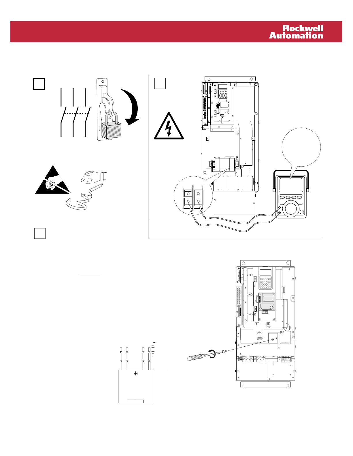
A. Locate the MOV assembly. Note wire placement
and remove the 4 wires/lugs from the terminal
block. Remove the screw that secures the MOV to
the chassis. See Figure 1
.
Optional
Communications
Module
PS–
PS+
22-10
AWG
5.3 IN-LB
WIRE STRIP
BR2
BR1 DC+ DC–
(0.6 N-M)
USE 75 C COPPER WIRE ONLY, TORQUE 52 IN-LB (6 N-M)
DC–DC+
USE 75 C
COPPER WIRE
ONLY
TORQUE
52 IN-LB
(6 N-M)
L2L1T3T2T1 L3
INPUTOUTPUT
Figure 1 MOV Assembly (Frame 5 shown)
0V
0V
B. Compare lug styles between the MOV just removed
and the new one.
– If the lugs are identical, install the new MOV in
reverse order. Verify correct wire placement and
tighten the MOV screw to 3.2 N-m (28 lb.-in.).
– If the lugs are different,
cut the lugs off of the new
8 (0.31 in.)
MOV (as close to the lug
as possible). Strip the
insulation from each lead
approximately 8 mm
(0.31 in.). Crimp the
supplied lugs to the wires.
Install the new MOV in
reverse order. Verify
correct wire placement
and tighten the MOV screw to 3.2 N-m (28 lb.in.).
POWER TERMINAL RATINGS
WIRE RANGE: 14-1/0 AWG (2.5-35 MM2)
TORQUE: 32 IN-LB (3.6 N-M)
STRIP LENGTH: 0.67 IN (17 MM)
USE 75 C CU WIRE ONLY
GROUND TERMINAL RATINGS (PE)
WIRE RANGE: 6-1/0 AWG (16-35 MM
TORQUE: 44 IN-LB (5 N-M)
STRIP LENGTH: 0.83 IN (21 MM)
17
2
)
21
Optional
Communications
Module
300 VDC EXT PWR SPLY TERM (PS+, PS-)
WIRE RANGE: 22-10 AWG (0.5-4 MM
TORQUE: 5.3 IN-LB (0.6 N-M)
STRIP LENGTH: 0.35 IN (9 MM)
2
)
9
INPUT ACOUTPUT
Page 2

*364600P01*
Publication RA-IN015A-EN-P – February, 2005 P/N 364600-P01
Copyright © 2005 Rockwell Automation, Inc. All rights reserved. Printed in USA.
 Loading...