

Page 1
Installation Instructions
Kinetix 7000 DC-DC Converter and Control Board Kits
Catalog Numbers 2099-K7KCP-1, 2099-K7KCB-1
Topic Page
About This Publication 1
About This Publication
Before Y
Remove the Drive Covers 4
Install the DC-DC Converter Kit 8
Install the Control Board Kit 9
Replace the DC-DC Converter Fuse 11
Additional Resources 12
This publication provides information for removing and replacing the dc-dc
converter, dc-dc converter fuse, and the control board assembly on Kinetix
7000 drive modules.
For additional information on mounting, wiring, configuring, and
troubleshooting
Servo Drive User Manual, publication
ou Begin 3
your Kinetix 7000 drive, refer to the Kinetix 7000 High Power
2099-UM001.
Page 2
2 Kinetix 7000 DC-DC Converter and Control Board Kits
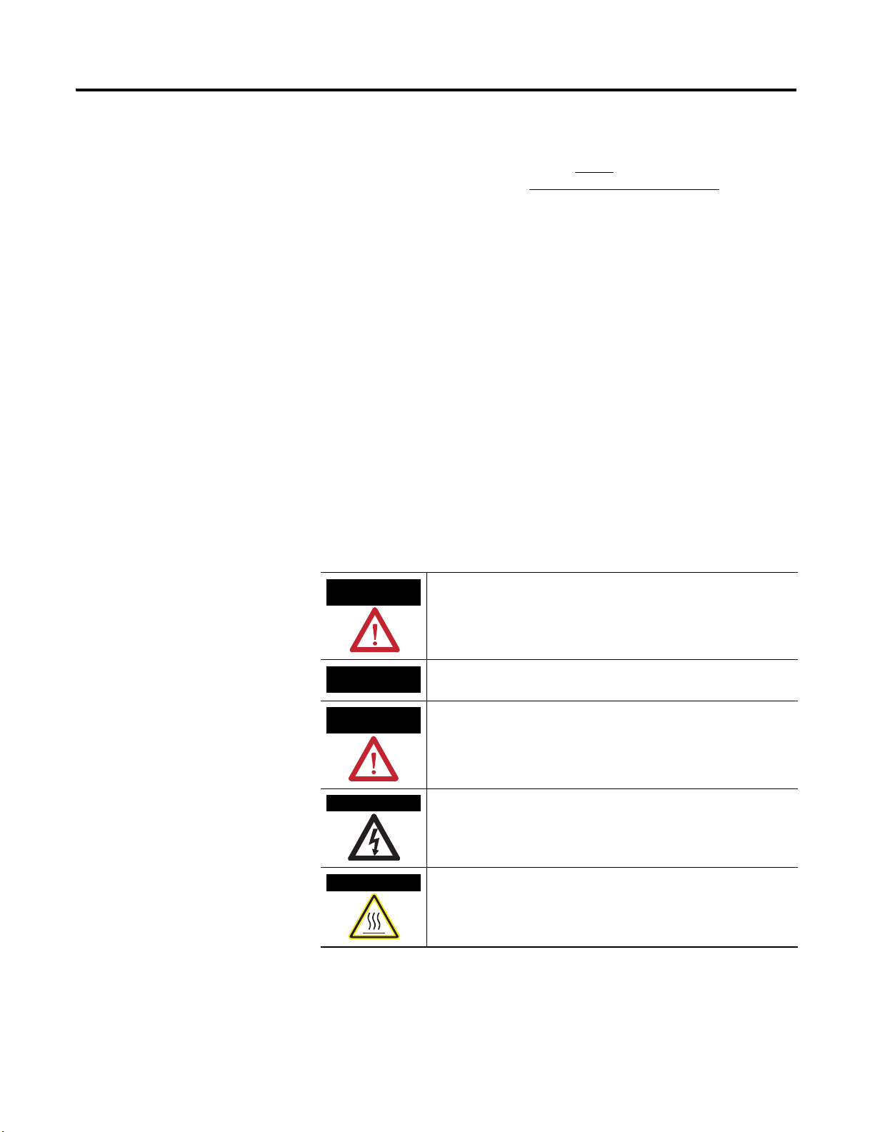
WARNING
IMPORTANT
ATTENTION
SHOCK HAZARD
BURN HAZARD
Important User Information
Solid state equipment has operational characteristics differing from those of
electromechanical equipment. Safety Guidelines for the Application, Installation and
Maintenance of Solid State Controls (publication
Automation sales office or online at http
some important differences between solid state equipment and hard-wired
electromechanical devices. Because of
of uses for solid state equipment, all persons responsible for applying this equipment must
satisfy themselves that each intended application of this equipment is acceptable.
In no event will Rockwell Automation, Inc. be responsible or liable for indirect or
consequential damages resulting from the use or application of this equipment.
The examples and diagrams in this manual are included solely for illustrative purposes.
Because of the many variables and requirements associated with any particular installation,
Rockwell Automation, Inc. cannot assume responsibility or liability for actual use based on
the examples and diagrams.
No patent liability is assumed by Rockwell Automation, Inc. with respect to use of
information, circuits, equipment, or software described in this manual.
Reproduction of the contents of this manual, in whole or in part, without written permission
of Rockwell Automation, Inc., is prohibited.
Throughout this manual, when necessary, we use notes to make you aware of safety
considerations.
://literature.rockwellautomation.com) describes
this difference, and also because of the wide variety
SGI-1.1 available from your local Rockwell
Identifies information about practices or circumstances that can cause
an explosion in a hazardous environment, which may lead to personal
injury or death, property damage, or economic loss.
Identifies information that is critical for successful application and
understanding of the product.
Identifies information about practices or circumstances that can lead
to personal injury or death, property damage, or economic loss.
Attentions help you to identify a hazard, avoid a hazard, and recognize
the consequences.
Labels may be on or inside the equipment, for example, a drive or
motor, to alert people that dangerous voltage may be present.
Labels may be on or inside the equipment, for example, a drive or
motor, to alert people that surfaces may reach dangerous
temperatures.
Publication 2099-IN002B-EN-P — October 2008
Page 3
Kinetix 7000 DC-DC Converter and Control Board Kits 3
ATTENTION
ATTENTION
Before You Begin
Make sure you have the following spare parts, tools, and have removed power
so you can safely remove the drive covers and assemblies.
Parts List
This publication provides installation instructions for removing and replacing
the following components:
• DC-DC con
• Control board assembly kit (catalog n
• DC-DC con
verter cassette kit (catalog number 2099-K7KCP-1)
umber 2099-K7KCB-1)
verter fuse (customer supplied)
Required Tools
• Phillips screwdriver
• Flat blade screwdriver
• 3/16 in. thin-walled socket, nut driver, or open-ended wrench
• 1/4 in. thin-walled socket, nut dri
ver, or open-ended wrench
Remove Power
Do not remove the Kinetix 7000 drive from the panel. Due to the
physical size and weight of the drives, perform these
procedures with the drive mounted to the panel.
Follow these steps to remove power from your drive.
1. Verify that all control and input power has been removed from the
system.
To avoid shock hazard or personal injury, assure that all
power has been removed before proceeding. This system
may have multiple sources of power. More than one
disconnect switch may be required to de-energize the
system.
Publication 2099-IN002B-EN-P — October 2008
Page 4
4 Kinetix 7000 DC-DC Converter and Control Board Kits
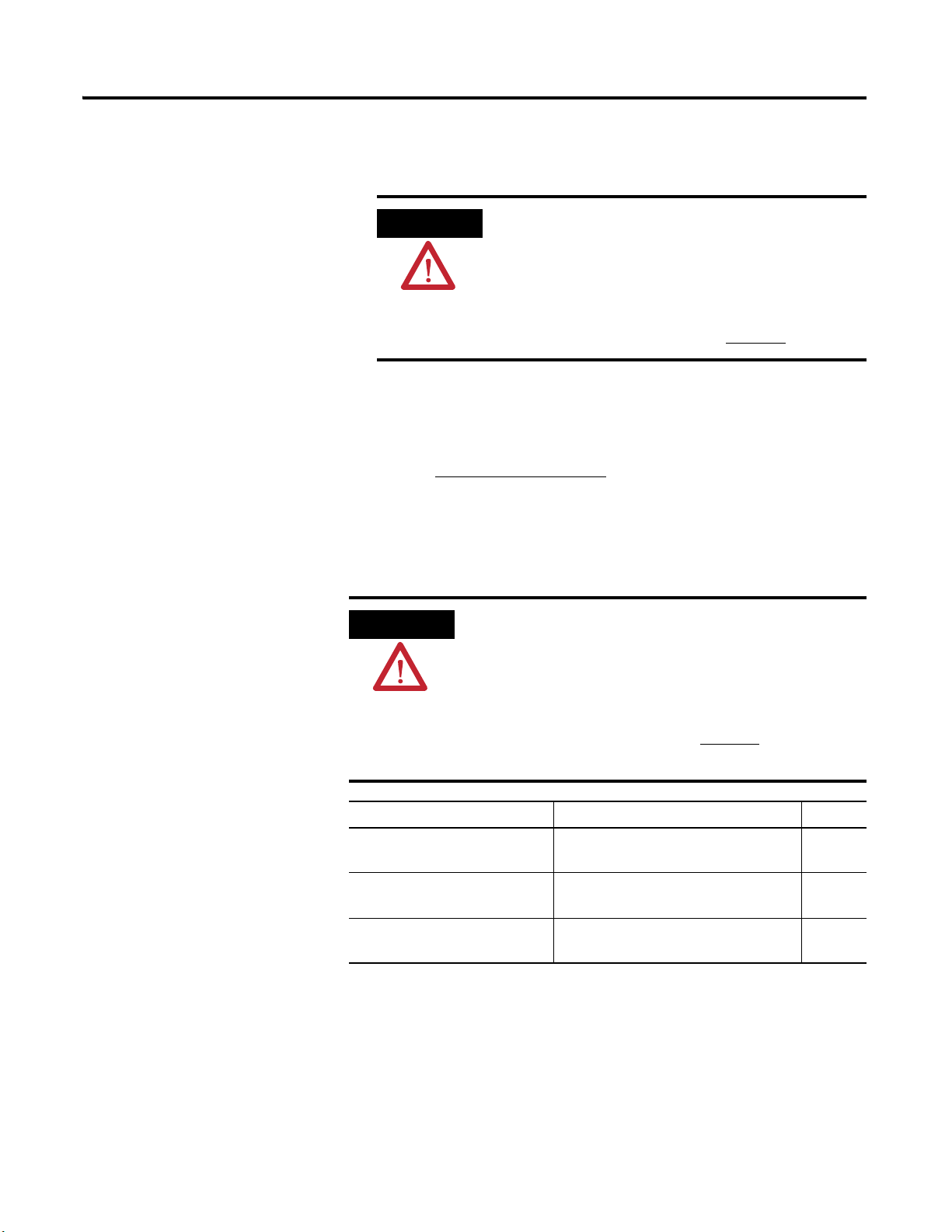
ATTENTION
ATTENTION
2. Allow five minutes for the dc bus to completely discharge before
proceeding.
3. Label and remove the fiber-optic (Tx and Rx) cables, and I/O (IOD),
motor feedback (MF), and auxiliary feedback (AF) connectors from the
drive.
This product contains stored energy devices. To avoid
hazard of electrical shock, verify that all voltage on
capacitors has been discharged before attempting to
service, repair, or remove this unit. You should only attempt
the procedures in this document if you are qualified to do
so and are familiar with solid-state control equipment and
the safety procedures in publication NFPA 70E
.
Remove the Drive Covers
4. Go to Remove the Drive Covers
.
Depending on the catalog number of your Kinetix 7000 drive, access to the
control board, dc-dc converter, and fuse varies.
This drive contains ESD (electrostatic discharge) sensitive parts
and assemblies. You are required to follow static control
precautions when you install, test, service, or repair this
assembly. If you do not follow ESD control procedures,
components can be damaged. If you are not familiar with static
control procedures, refer to Guarding Against Electrostatic
Damage Service Bulletin,
publication 8000-4.5.2, or any other
applicable ESD protection handbook.
Cat. No. Topic Page
2099-BM06-S, 2099-BM07-S, or
2099-BM08-S
2099-BM09 -S or 2099-BM10-S Remove 2099-BM09-S and 209
Remove 2099-BM06-S, 2099-BM07-S,
and 2099-BM08-S Covers
9-BM10-S
Covers
5
6
Publication 2099-IN002B-EN-P — October 2008
2099-BM11-S, or 2099-BM12-S Remove 2099-BM11-S and 2099-BM12-S
Covers
7
Page 5
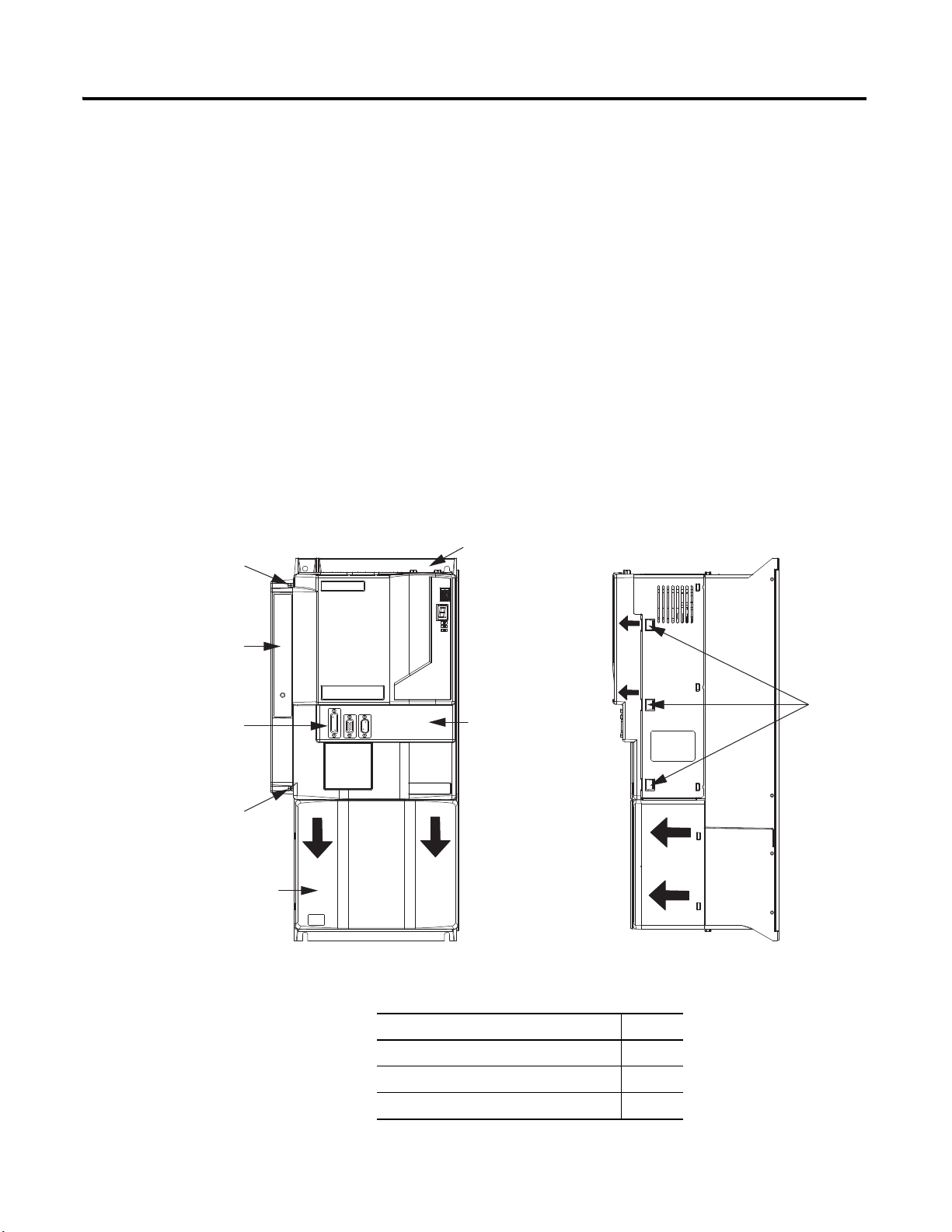
Kinetix 7000 DC-DC Converter and Control Board Kits 5
Kinetix 7000 Drive
(2099-BM07-S side view)
Snap-fits
Top Cover
Side View
Front View
DC-DC Converter Cover
Bottom Cover
Upper DC-DC Converter Cover
Captive Screw
Lower DC-DC Converter Cover
Captive Screw
I/O and Feedback
(IOD, MF, and AF) Connectors
Fiber-optic (Tx and Rx) Connectors
Remove 2099-BM06-S, 2099-BM07-S, and 2099-BM08-S Covers
Follow these steps to remove the drive covers.
1. Remove the bottom cover.
a. Pull the cover downward approximately 12 mm (0.5 in.).
b. Pull the cover straight out and away from the drive.
2. Remove the two dc-dc converter cover screws.
3. Pull the dc-dc converter cover outward and away from the drive.
4. Depress the three top cover snap-fits on the right-hand side of the top
cover and pull the cover slightly outward and away from the drive.
5. Pivot the top cover to the left and maneuver the cover out from under
the slots on the left-hand side of the top cover.
6. Install your kit.
Topic Page
Install the DC-DC Converter Kit 8
Install the Control Board Kit 9
Replace the DC-DC Converter Fuse 11
Publication 2099-IN002B-EN-P — October 2008
Page 6

6 Kinetix 7000 DC-DC Converter and Control Board Kits
Kinetix 7000 Drive
(2099-BM09-S is shown)
Snap-fits
Top Cover
Side ViewFront View
DC-DC Converter Cover
Bottom Cover
Upper DC-DC Converter Cover
Captive Screw
Lower DC-DC Converter Cover
Captive Screw
I/O and Feedback
(IOD, MF, and AF) Connectors
Fiber-optic (Tx and Rx) Connectors
Top Cover Screw
Cover Fastening Rod
Remove 2099-BM09-S and 2099-BM10-S Covers
Follow these steps to remove the drive covers.
1. Remove the two dc-dc converter cover screws.
2. Pull the dc-dc converter cover outward and away from the drive.
3. Pull the top cover fastener rod upward approximately 12 mm (0.5 in.).
If the rod is pulled far enough, the three latch points on the rod will
disengage with the chassis.
4. Remove the top cover screw.
5. Depress the two snap-fits on the right-hand side of the top cover and
pull the cover outward and away from the drive.
Publication 2099-IN002B-EN-P — October 2008
6. Install your kit.
Topic Page
Install the DC-DC Converter Kit 8
Install the Control Board Kit 9
Replace the DC-DC Converter Fuse 11
Page 7

Kinetix 7000 DC-DC Converter and Control Board Kits 7
Kinetix 7000 Drive
(2099-BM11-S is shown)
Top Cover
DC-DC Converter Cover
Bottom Cover
Upper DC-DC Converter Cover
Captive Screw
Lower DC-DC Converter Cover
Captive Screw
I/O and Feedback
(IOD, MF, and AF) Connectors
Fiber-optic (Tx and Rx) Connectors
Bottom Cover Captive Screws
Lower Top Cover Screws
(under bottom cover)
Top Cover Captive Screws
Remove 2099-BM11-S and 2099-BM12-S Covers
Follow these steps to remove the drive covers.
1. Loosen the two bottom-cover captive screws and pull the cover slightly
away from the drive module.
2. Slide the bottom cover downward until the upper tabs clear the top
cover slots.
3. Loosen the two lower-top cover screws.
These screws were covered by the bottom cover.
4. Loosen the two top-cover captive screws and pull the cover slightly away
from the drive module.
5. Slide the top cover upward until the cover clears the lower screws.
6. Remove the two dc-dc converter cover screws.
7. Pull the dc-dc converter cover outward and away from the drive.
8. Install your kit.
Topic Page
Install the DC-DC Converter Kit 8
Install the Control Board Kit 9
Replace the DC-DC Converter Fuse 11
Publication 2099-IN002B-EN-P — October 2008
Page 8

8 Kinetix 7000 DC-DC Converter and Control Board Kits
Kinetix 7000 Drive
(2099-BM07-S side view)
Kinetix 7000 Drive
(2099-BM07-S top view)
DC-DC
Converter
Cassette
Upper DC-DC Converter Cover
Captive Screw
Lower DC-DC Converter Cover
Captive Screw
DC-DC Converter
Wiring Harness
DC-DC Converter
Cassette
Captive Screw
DC-DC Converter
Cassette Latch
Install the DC-DC Converter
Follow these steps to remove and replace the dc-dc converter cassette.
Kit
1. Loosen the upper and lower dc-dc converter screws.
T
urn the screws until the latch disengag
es from the cassette. The upper
screw and latch are shown, the lower screw latches the same way.
2. Remove the dc-dc converter wiring harness.
Un
plug the two connectors and route through slot in cassette
3. Pull the dc-dc con
verter cassette straight out and away from the drive.
4. Replace the dc-dc converter cassette.
5. Replace the wiring harness.
Route the two connectors back through the
slot in the cassette and
reseat the two-position and three-position connectors.
6. Tighten the upper and lower dc-dc converter screws.
urn the screws until the latch engages with the cassette. The upper
T
screw and latch are
shown, the lower screw latches the same way. Torque
screws to 0.45 N•m (4.0 in•lb).
7. Replace the dc-dc converter cassette and drive covers.
.
Publication 2099-IN002B-EN-P — October 2008
Page 9

Kinetix 7000 DC-DC Converter and Control Board Kits 9
IMPORTANT
Kinetix 7000 Drive
(2099-BM07-S is shown)
Ribbon Cable
Connector
Control Board
Screws
Control Board
Connector Plate
Connector Plate
Screws, 2x
Connector Plate
Stand-offs, 2x
Connector Stand-offs, 6x
SO, GPIO, GPR, and
Fiber-optic Connectors
Display Board
IMPORTANT
Refer to Remove the Drive Covers on page 4 and reverse the order of
steps for your drive module.
When replacing the top cover, temporarily remove the
fiber-optic cables from the drive Tx and Rx connectors. This
allows the top cover to seat properly with the chassis.
8. Return the drive to operation.
Install the Control Board Kit
Follow these steps to remove and replace the control board.
1. Label and remov
e the safe-off (SO), general purpose I/O (GPIO),
general purpose relay (GPR), and ribbon cable connectors from the
control board.
Also, label and remove the fiber-optic (Tx and Rx) connectors, if not
removed earlier.
2. Remove the six connector stand-offs by using a 3/16 in. thin-walled
socket or nut driver.
Thin-walled socket or open-ended wrench is required to
remove the screws due to the clearance between screw
and connector.
3. Remove the two connector plate screws by using a small Phillips
screwdriver.
Publication 2099-IN002B-EN-P — October 2008
Page 10

10 Kinetix 7000 DC-DC Converter and Control Board Kits
ATTENTION
IMPORTANT
4. Remove the connector plate.
5. Remove the two connector plate stand-offs by using a 1/4 in.
thin-walled socket, nut driver, or open-ended wrench.
6. Remove the five control board screws.
7. Remove and replace the control board.
Verify the control board pins are fully inserted into display board.
8. Replace the screws, stand-offs, connector plate, and ribbon cable as
described in steps 1...6 above.
To avoid damage to small components adjacent to the
stand-offs, use a thin-walled socket or open-ended wrench
to remove the stand-offs.
Screw Torque Value
Connector plate stand-offs (2x)
Connector plate screws (2x)
Connector stand-offs (6x)
Control board screws (5x)
0.68 N•m (6.0 in
•lb)
9. Replace the dc-dc converter cassette cover and drive covers.
Refer to Remove the Drive Covers
on page 4 and reverse the order of
steps for your drive module.
When replacing the top cover, temporarily remove the
fiber-optic cables from the drive Tx and Rx connectors. This
allows the top cover to seat properly with the chassis.
10. Return the drive to operation.
Publication 2099-IN002B-EN-P — October 2008
Page 11

Kinetix 7000 DC-DC Converter and Control Board Kits 11
Kinetix 7000 Drive
(2099-BM07-S is shown)
DC-DC Converter Fuse
DC-DC Converter Cassette
LittelFuse
7.5 A, 32V dc
PN 29707.5
IMPORTANT
Replace the DC-DC Converter Fuse
To access the dc-dc converter fuse, the dc-dc converter cassette cover must be
removed.
1. Remove the dc-dc converter cassette cover.
Refer to Remove the Drive Covers
on page 4 and follow the procedure
for your drive.
2. Replace the fuse.
3. Replace the dc-dc converter cassette cover.
4. Return the drive to operation.
Refer to Additional Resources
on page 12 for manufacturers datasheet
information.
Refer to Remove the Drive Covers
steps for your drive module.
When replacing the top cover, temporarily remove the
fiber-optic cables from the drive Tx and Rx connectors. This
allows the top cover to seat properly with the chassis.
on page 4 and reverse the order of
Publication 2099-IN002B-EN-P — October 2008
Page 12

12 Kinetix 7000 DC-DC Converter and Control Board Kits
Additional Resources
The following documents contain additional information for this Rockwell
Automation product and related products.
Resource Description
Kinetix 7000 High Power Servo Drives User Manual,
publication 2099-UM001
LittelFuse, Inc. website http://littelfuse.com
Guarding Against Electrostatic Damage Service Bulletin,
publication 8000-4.5.2
Rockwell Automation Industrial Automation Glossary, publication AG-7.1
Replacement fuse datasheet for dc-dc converter.
Information on installing, configuring, startup, troubleshooting, and
applications for your Kinetix 7000 servo drive system.
Industry best practices for preventing damage due to electrostatic
discharge (ESD).
A glossary of industrial automation terms and abbreviations.
You can view or download publications at
http://literature.rockwellautomation.com. To order paper copies of technical
documentation, contact your local Rockwe
representative.
ll Automation distributor or sales
Publication 2099-IN002B-EN-P — October 2008
Page 13

Notes:
Kinetix 7000 DC-DC Converter and Control Board Kits 13
Publication 2099-IN002B-EN-P — October 2008
Page 14

14 Kinetix 7000 DC-DC Converter and Control Board Kits
Notes:
Publication 2099-IN002B-EN-P — October 2008
Page 15

Notes:
Kinetix 7000 DC-DC Converter and Control Board Kits 15
Publication 2099-IN002B-EN-P — October 2008
Page 16

Rockwell Automation Support
Rockwell Automation provides technical information on the Web to assist you in using its products. At
http://support.rockwellautomation.com
notes, sample code and links to software service packs, and a MySupport feature that you can customize to make the best use of
these tools.
For an additional level of technical phone support for installation, configuration, and troubleshooting, we offer TechConnect
support programs. For more information, contact your local distributor or Rockwell Automation representative, or visit
http://support.rockwellautomation.com
Installation Assistance
If you experience a problem within the first 24 hours of installation, please review the information that's contained in this manual.
You can also contact a special Customer Support number for initial help in getting your product up and running.
United States 1.440.646.3434
Monday – Friday, 8 a.m. – 5 p.m. EST
Outside United States Please contact your local Rockwell Automation representative for any technical support issues.
, you can find technical manuals, a knowledge base of FAQs, technical and application
.
New Product Satisfaction Return
Rockwell Automation tests all of its products to ensure that they are fully operational when shipped from the manufacturing
facility. However, if your product is not functioning and needs to be returned, follow these procedures.
United States Contact your distributor. You must provide a Customer Support case number (see phone number
above to obtain one) to your distributor in order to complete the return process.
Outside United States Please contact your local Rockwell Automation representative for the return procedure.
Allen-Bradley, CompactLogix, ControlLogix, Kinetix, Rockwell Automation, RSLogix 5000, SoftLogix, and TechConnect are trademarks of Rockwell Automation, Inc.
Trademarks not belonging to Rockwell Automation are property of their respective companies.
Publication 2099-IN002B-EN-P — October 2008 PN 351781-P02
Supersedes Publication 2099-IN002A-EN-P — Febru ary 2007 Copyright © 2008 Rockwell Automation, Inc. All rights reserved. Prin ted in the U.S.A.
 Loading...