

Page 1
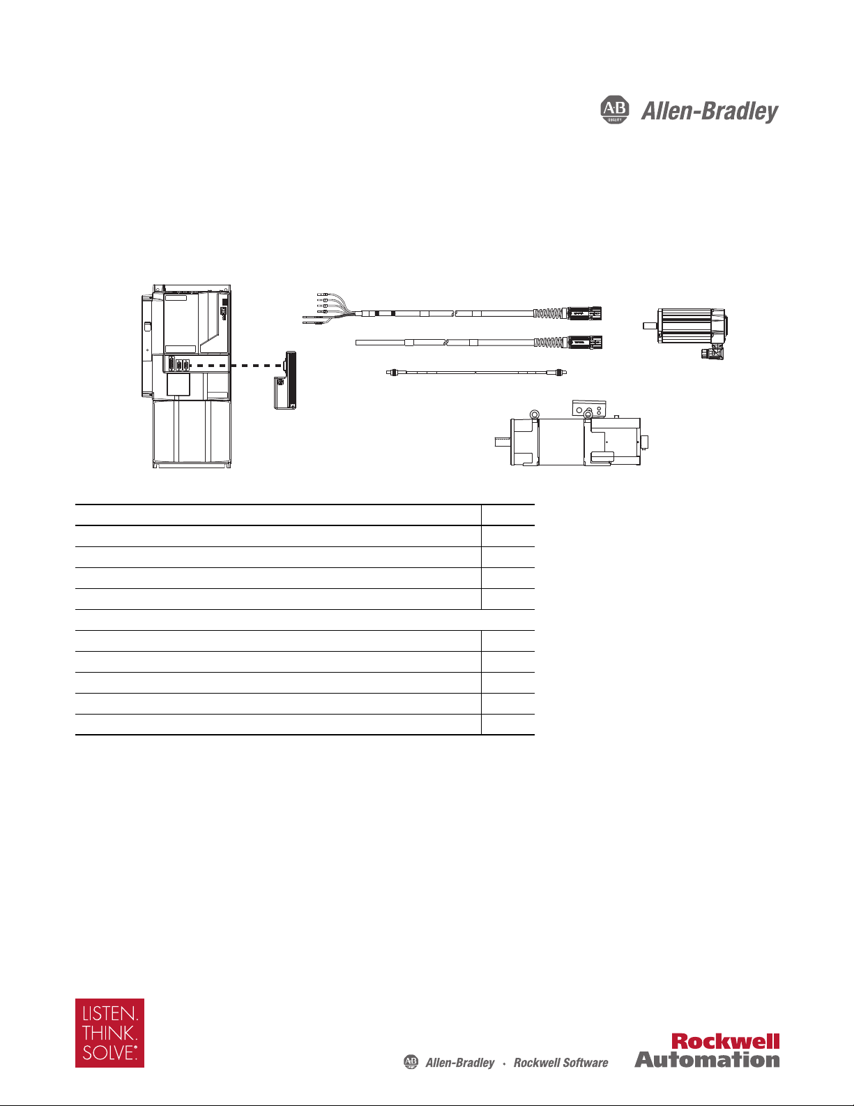
Design Guide
Motor Cables, Interface Cables,
Connector Kits, and Other Drive
Accesso ries
Kinetix 7000
Servo Drives
Rotary Motion
Servo Motors
Rotary Motion
Induction Motors
Kinetix 7000 Drive Systems
Catalog Numbers 2099-BM06-S, 2099-BM07-S, 2099-BM08-S, 2099-BM09-S, 2099-BM10-S, 2099-BM11-S, 2099-BM12-S
Top ic Pag e
Introduction 2
Determine What You Need 3
Kinetix 7000 System Examples 4
2090-Series Motor/Actuator Cables Overview 9
Rotary Motion System Combinations
HPK-Series Asynchronous Servo Motors 11
MP-Series Low Inertia Motors 17
MP-Series Medium Inertia Motors 22
RDD-Series Direct Drive Motors 27
Additional Resources 30
Page 2

Kinetix 7000 Drive Systems
IMPORTANT
Introduction
This publication assumes that the drive family for your application is Kinetix® 7000 and that you have already determined
your motor catalog number. To revisit those decisions, refer to the Kinetix Motion Control Selection Guide, publication
GMC-SG001
The purpose of this publication is to assist you in identifying the drive system components and accessory items you’ll need
for your Kinetix 7000 drive/motor combination. Diagrams in this publication illustrate how many of the common drive
accessory items are used in a typical system, but refer to the Kinetix Motion Accessories Technical Data, publication
GMC-TD004
Also provided are drive/motor or drive/actuator system combinations that include the following:
• Motor/cable combinations table
• Drive/motor performance specification table
• Torque/speed curves with each motor matched to the drive with optimum performance
Performance specification data and curves reflect nominal system performance of a typical system with motor/drive at
rated ambient temperature and line voltage. For additional information on ambients, line conditions, and valid
combinations not shown in this publication, refer to Motion Analyzer software.
, or Motion Analyzer software.
, for detailed accessory descriptions and specifications.
These system combinations do not include all possible motor/drive combinations. Please refer to Motion Analyzer software to
verify compatibility. Download is available at http://www.ab.com/motion/software/analyzer.html
.
2 Rockwell Automation Publication GMC-RM007A-EN-P - September 2011
Page 3
Kinetix 7000 Drive Systems
Determine What You Need
For each Kinetix 7000 drive system, you need to know the drive and motor catalog numbers to determine the motor power
and feedback cable catalog numbers. Interface cables and connector kits are also required. Optional equipment includes the
line interface module (LIM), AC line filter, Bulletin 8720MC regenerative power supply (RPS), and others. Example
diagrams of the required equipment listed on this page are shown on page 4
Kinetix 7000 Drive Modules
.
Drive Cat. No.
2099-BM06-S
2099-BM07-S 30 kW 40 Hp 52 A rms
2099-BM08-S 37 kW 50 Hp 65 A rms
2099-BM09-S 56 kW 75 Hp 96 A rms
2099-BM10-S 75 kW 100 Hp 125 A rms
2099-BM11-S 112 kW 150 Hp 180 A rms
2099-BM12-S 149 kW 200 Hp 248 A rms
(1) The -S designator indicates safe-off safety func tionality.
(1)
Input Voltage Output Power (continuous)
22 kW 30 Hp 40 A rms
400V series,
Three-phase
Output Current
(continuous)
Refer to the Kinetix Servo Drives Technical Data, publication GMC-TD003, for detailed descriptions and additional
specifications for the Kinetix 7000 drive family.
Required Drive Accessories
Drive Accessory Description Cat. No.
24V power supply
Low-profile connector kits
(required for flying-lead cables)
SERCOS fiber-optic cables
(required as needed)
Motor power and feedback cables
24V DC for control power and motor
brakes
Motor feedback connections
Auxiliary feedback connections 2094-K6CK-D15F
I/O connections 2094-K6CK-D26M
Plastic, in-cabinet duty 2090-SCEPx-x
Plastic, on-machine duty 2090-SCNPx-x
Plastic, outdoor and conduit duty 2090-SCVPx-x
Glass, outdoor and conduit duty 2090-SCVGx-x
Refer to the specific drive/motor combination for the motor cables required for
your system.
1606-XLxxx
2094-K6CK-D15M
2094-K7CK-KENDAT
(1)
(1) Applies to only Bulletin RDB direc t-drive motors with EnDat encoder.
Refer to the Kinetix Motion Accessories Technical Data, publication GMC-TD004, for detailed descriptions and
specifications of these servo drive accessories.
Rockwell Automation Publication GMC-RM007A-EN-P - September 2011 3
Page 4
Kinetix 7000 Drive Systems
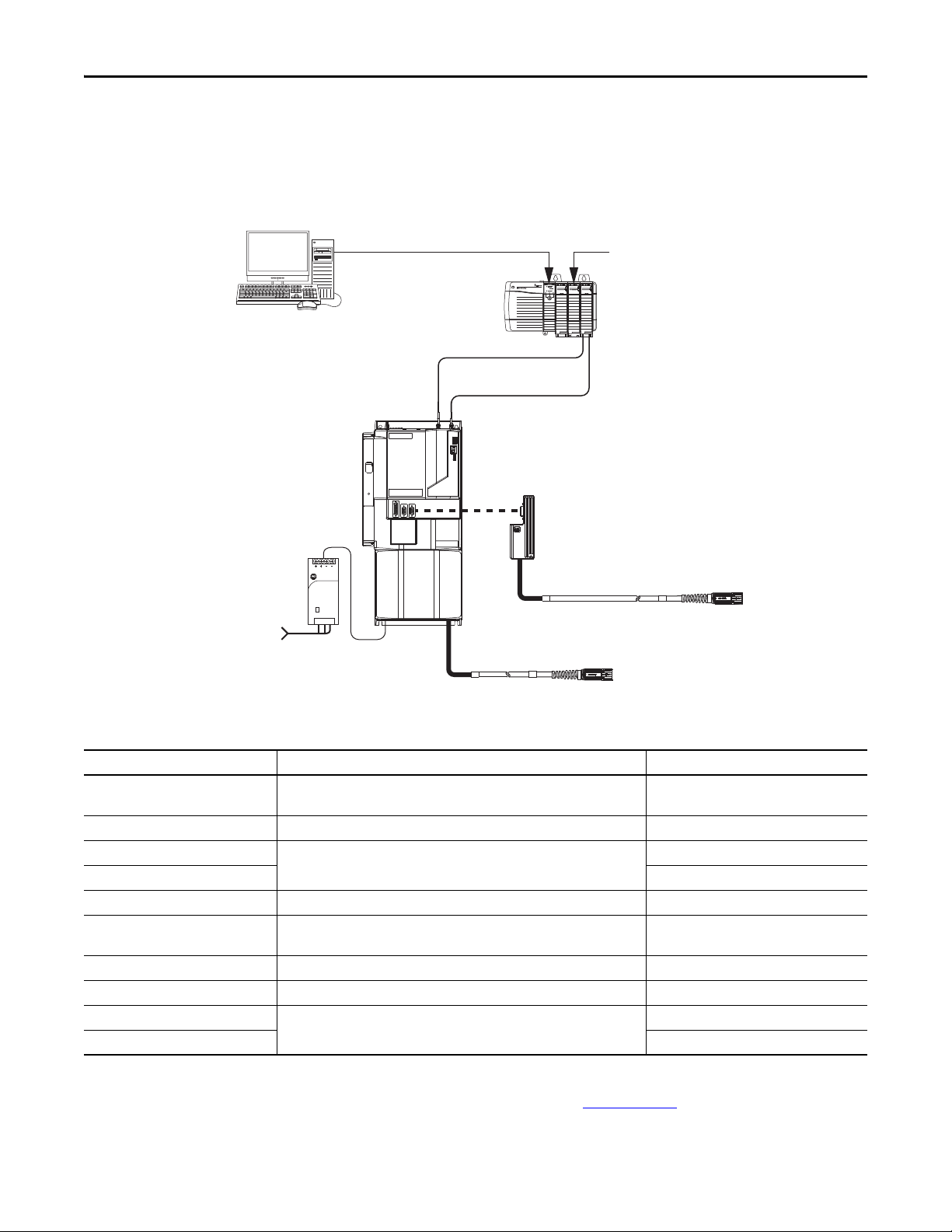
2090-SCxxx-x
SERCOS Fiber-optic Cables
2099-BMxx-S
Kinetix 7000 Servo Drive
2094-K6CK-xxxx
(1)
Low-profile Connector Kits for
Motor Feedback, I/O, and Auxiliary Feedback
Bulletin 2090 Motor Feedback Cable
Bulletin 2090 Motor Power Cable
Logix SERCOS interface Module
24V DC
Control Power
1606-XLxxx
Control Power
Supply Input
Logix Controller Platform
(ControlLogix® controller is shown)
RSLogix™ 5000
Software
Logix Controller Programming Network
Kinetix 7000 System Examples
These system examples illustrate how the required drive modules and accessories are used in typical systems.
Kinetix 7000 System Example (SERCOS interface)
Allen-Bradley
1606-XL
Power Supply
Input
(1) RDD-Series direct-drive motors require 2090-K7CK-KENDAT low-profile feedback modules.
Optional Drive Accessories
Drive Accessory Description Cat. No.
2094 line interface module
2090 AC line filters AC line conditioning for EMC. 2090-XXLF-TCxxxx
Safety headers
Safety interface cables 1202-Cxx
External auxiliary encoders Allen-Bradley® sine/cosine and incremental external encoders. Bulletin 842A, 844D, 845H, and 845T
Connector set
Control board kit Control board assembly kit. Replacement control board. 2099-K7KCB-1
DC-DC converter kit DC-DC converter cassette kit. Replacement DC-DC converter. 2099-K7KCP-1
8720MC regenerative power supply (RPS)
8720MC line reactors 8720MC-LRxx-xxxx
Motor-end cable connector kits, for use when building your own cables, and panel-mounted breakout components are also
available. Refer to the Kinetix Motion Accessories Technical Data, publication GMC-TD004
specifications of these servo drive accessories.
4 Rockwell Automation Publication GMC-RM007A-EN-P - September 2011
Replaces many of the common input power devices for your drive system (including
24V DC supply).
Cascading safe-off connections from drive-to-drive.
Replacement connectors for safe-off (SO), general purpose I/O (GPIO), general
purpose relay (GPR), and control power (CP) connectors.
Power components required in regenerative applications.
2094-BLxxS, 2094-BL02, 2094-XL75S-Cx
2090-XNSM-x
2099-K7KCK-1
8720MC-RPSxxx
, for detailed descriptions and
Page 5
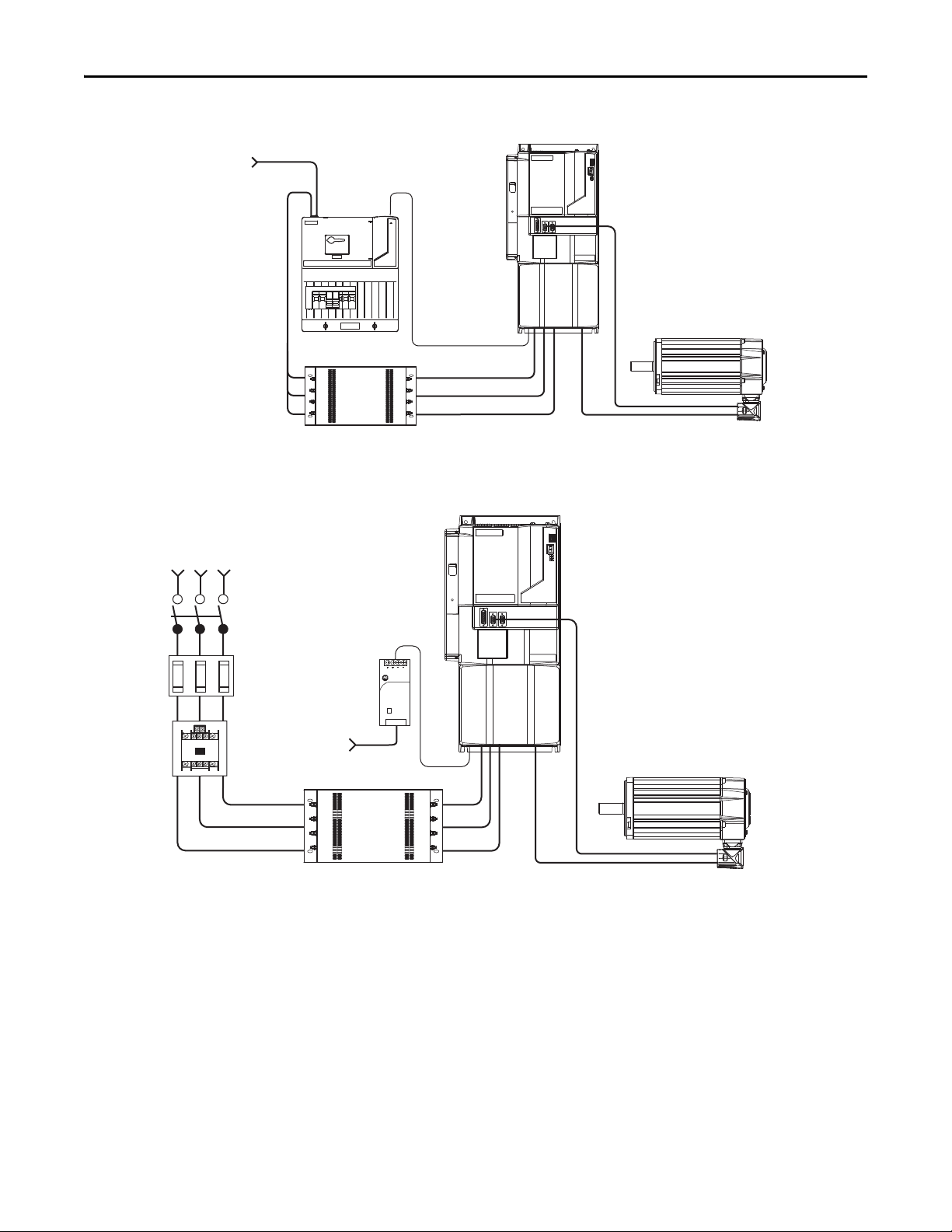
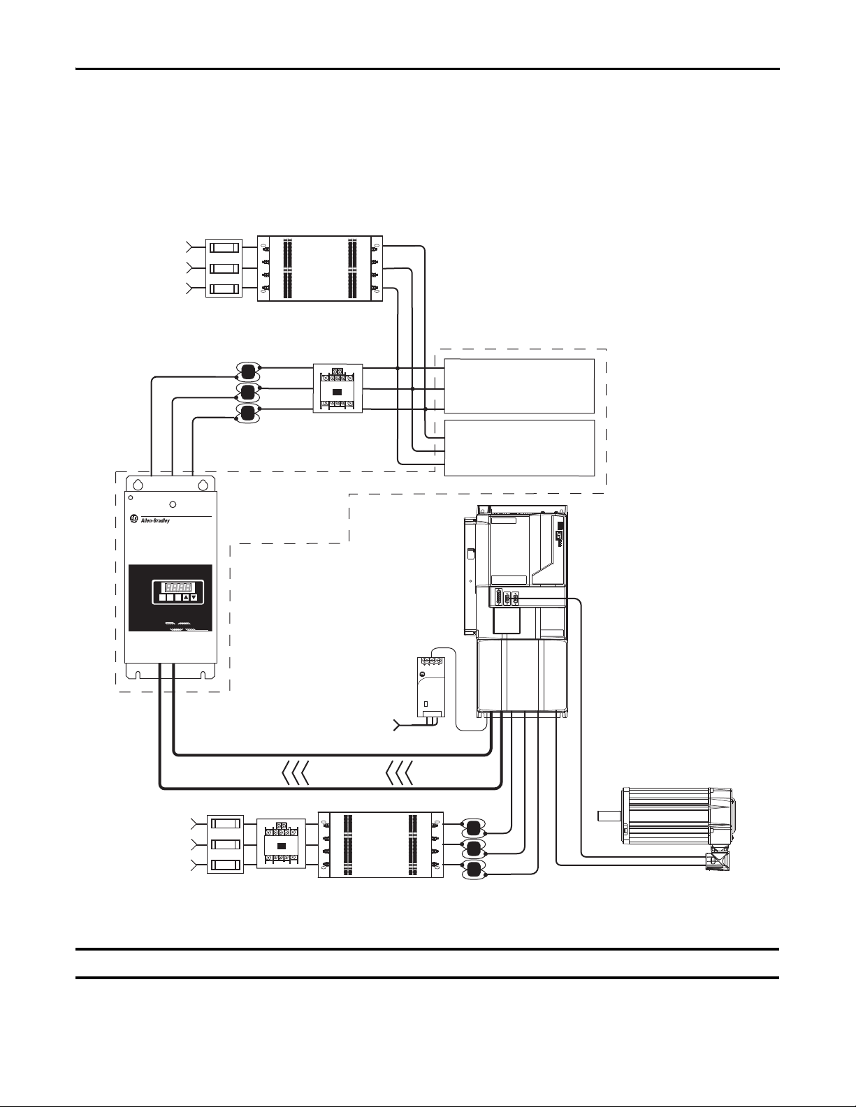
Kinetix 7000 AC Input Power Example (with LIM module)
Three-phase
Input Power
24V DC
Control Power
2090-XXLF-TCxxxx
AC Lin e Filter
2094-xLxxS
Line Interface Module
(optional component)
2099-BM06-S, 2099-BM07-S,
2099-BM08-S Servo Drives
HPK-Series, RDD-Series, and
MP-Series (Bulletin MPL or MPM)
Servo Motors
External Shunt Module (optional component)
Refer to Rockwell Automation Encompass™ Partners
Kinetix 7000 Drive
2099-BMxx-S
24V DC
Control Power
1606-XLxxx
External Shunt Module (optional component)
Refer to Rockwell Automation Encompass Partners
Control Power
Supply Input
Line
Disconnect
Device
Magnetic
Contac tor
Input
Fusing
Three-phase
Input Power
AC Lin e Filter
2090-XXLF-TCxxxx
(required for CE)
HPK-Series, RDD-Series, and
MP-Series (Bulletin MPL or MPM)
Servo Motors
Kinetix 7000 AC Input Power Example (without LIM module)
Kinetix 7000 Drive Systems
Allen-Bradley
1606-XL
Power Supply
Input
Rockwell Automation Publication GMC-RM007A-EN-P - September 2011 5
Page 6
Kinetix 7000 Drive Systems
IMPORTANT
1606-XL
Power Supply
Input
Allen-Bradley
R
E
G
E
N
E
R
A
T
IV
E
P
O
W
E
R
S
U
P
P
L
Y
R
E
G
E
N
E
R
A
T
IV
E
P
O
W
E
R
S
U
P
P
L
Y
87208720
MCMC
RST
PRG
ENT
READYREADY
FAULTFAULT
PROGRAMPROGRAM kWkW
V
A
DC Bus
Regenerative Power Supply
8720MC-RPS065-BM-HV2
Common Bus Leader
Line Reactor
8720MC-LRxx
Three-phase
Input Power
Varistor (8720MC-VA-B)
Included with
8720MC-RPS065-BM-HV2.
Harmonic Filter (8720MC-HF-B2)
Included with
8720MC-RPS065-BM-HV2.
Magnetic
Contac tor
24V DC
Control Power
1606-XLxxx
AC Line Filter 8720MC-RFI80
(required for CE)
Input
Fusing
Three-phase
Input Power
Magnetic
Contactor
Input
Fusing
Line Reactor
8720MC-LRxx
Regenerative
Power Only
Kinetix 7000 Drive
2099-BMxx-S
Common Bus Follower
Control Power
Supply Input
AC Lin e Filter
2090-XXLF-TCxxxx
(required for CE)
HPK-Series, RDD-Series, and
MP-Series (Bulletin MPL or MPM)
Servo Motors
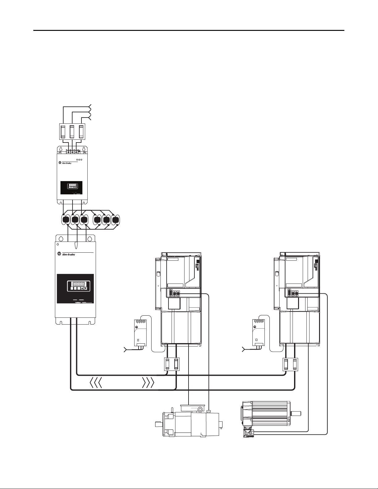
In this example, the Kinetix 7000 drive system is shown with the 8720MC Regenerative Power Supply (RPS) in a
regenerative braking configuration. Harmonic filter and varistor are available separately, but are included with the RPS unit
when ordering catalog number 8720MC-RPS065-BM-HV2.
In this configuration, the Kinetix 7000 drive provides motoring power and the RPS unit provides regenerative power.
Kinetix 7000 AC Input Power Example (with regenerative power)
Regenerative braking applications are limited to only one Kinetix 7000 common-bus follower drive.
6 Rockwell Automation Publication GMC-RM007A-EN-P - September 2011
Page 7

Kinetix 7000 Drive Systems
R
E
G
E
N
E
R
A
T
IV
E
P
O
W
E
R
S
U
P
P
LY
REG
E
N
ERAT
IVE POW
ER SUP
PLY
87208720
MCMC
RST
PRG
ENT
READYREADY
FAULTFAULT
PROGRAMPROGRAM kWkW
V
A
1606-XL
Power Supply
Input
Allen-Bradley
1606-XL
Power Supply
Input
Allen-Bradley
Kinetix 7000 Drive
2099-BMxx-S
Common Bus Follower
Regenerative Power Supply
8720MC-RPS065-BM-HV2
Common Bus Leader
Line Reactor
8720MC-LRxx
Three-phase
Input Power
Varistor (8720MC-VA-B)
is included with
8720MC-RPS065-BM-HV2.
Harmonic Filter (8720MC-HF-B2)
is included with
8720MC-RPS065-BM-HV2.
Magnetic
Contac tor
AC Line Filter 8720MC-RFI80
(required for CE)
Input
Fusing
Kinetix 7000 Drive
2099-BMxx-S
Common Bus Follower
DC Bus
Full Re generative
DC Bus
Fusing
DC Bus
Fusing
24V DC
Control Power
1606-XLxxx
Control Power
Supply Input
24V DC
Control Power
1606-XLxxx
Control Power
Supply Input
MP-Series (Bulletin MPL or MPM) and
RDD-Series Servo Motors
HPK-Series Asynchronous
Servo Motors
In this example, the Kinetix 7000 drive system is shown with the 8720MC Regenerative Power Supply (RPS) in
DC common-bus configuration with two follower Kinetix 7000 drives. Harmonic filter and varistor are available
separately, but are included with the RPS unit when ordering catalog number 8720MC-RPS065-BM-HV2.
In this full-line regenerative example, the 8720MC-RPS065 unit provides motoring power and regenerative braking.
Kinetix 7000 DC Input Power Example (full-line regeneration)
Rockwell Automation Publication GMC-RM007A-EN-P - September 2011 7
Page 8
Kinetix 7000 Drive Systems
1606-XL
Power Supply
Input
Allen-Bradley
R
E
G
E
N
E
R
A
T
IV
E
P
O
W
E
R
S
U
P
P
LY
R
E
G
E
N
E
R
AT
IV
E
P
O
W
E
R
S
U
P
P
L
Y
87208720
MCMC
RST
PRG
ENT
READYREADY
FAULTFAULT
PROGRAMPROGRAM kWkW
V
A
1606-XL
Power Supply
Input
Allen-Bradley
R
E
G
E
N
E
R
A
T
IV
E
P
O
W
E
R
S
U
P
P
L
Y
87208
7
2
0
MCM
C
RST
PRG
ENT
READYREADY
FAULFAULT
PROGRAM
PROGRAM kWkW
V
A
DC Bus
Kinetix 7000 Drive
2099-BM11-S
Common Bus Follower
Regenerative Power Supply
8720MC-RPS190-BM
Common Bus Leader
Line Reactor
8720MC-LR10-100B
(two units in parallel)
Three- phase
Input Power
EMC Line Filter 8720MC-EF190-VB
This unit includes an AC line filter (required for CE),
magnetic contactor, harmonic filter, and varistor.
IMPORTANT The Bulletin 8720MC line filter unit and
line reactor are required when using the
8720MC-RPS190 regenerative power supply.
Input
Fusing
Full Regenerative
Kinetix 7000 Drive
2099-BM11-S
Common Bus Follower
24V DC
Control Power
1606-XLxxx
24V DC
Control Power
1606-XLxxx
HPK-Series Asynchronous
Servo Motors
DC Bus
Fusin g
DC Bus
Fusing
Control Power
Supply Input
Control Power
Supply Input
MP-Series (Bulletin MPL or MPM)
and RDD-Series Servo Motors
In this example, the Kinetix 7000 drive system is shown with the 8720MC Regenerative Power Supply (RPS) in
DC common-bus configuration with two follower 2099-BM11-S drives. Harmonic filter, varistor, and magnetic contactor
are included when ordering the 8720MC-EF190-VB EMC line filter.
In this full-line regenerative example, the 8720MC-RPS190 unit provides motoring power and regenerative braking.
Kinetix 7000 DC Input Power Example (with full-line regeneration)
8 Rockwell Automation Publication GMC-RM007A-EN-P - September 2011
Page 9
2090-Series Motor/Actuator Cables Overview
IMPORTANT
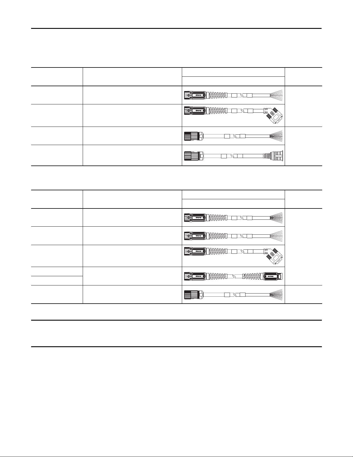
Feedback Cable Descriptions (standard, non-flex)
Kinetix 7000 Drive Systems
Standard Cable
Cat. No.
2090-CFBM7DF-CEAAxx
2090-CFBM7DD-CEAAxx
2090-XXNFMF-Sxx
2090-CFBM4E2-CATR
(1) Threaded DIN connector (motor end) and bayonet connector for 2090-XXNFMP-Sxx cable.
Description
• Drive-end flying-leads (DF)
• High-resolution or resolver applications (CE)
• Drive-end 15-pin connector (DD)
• High-resolution or resolver applications (CE)
• Drive-end flying-leads
• High-resolution or incremental applications
• Drive-end bayonet (E2), transition (TR) cable
• Motor-end threaded DIN (M4)
• All feedback types (CA)
Feedback Cable Descriptions (continuous-flex)
Continuous-flex Cable
Cat. No.
2090-CFBM7DF-CDAFxx
2090-CFBM7DF-CEAFxx
2090-CFBM7DD-CEAFxx
Description
• Drive-end flying-leads (DF)
• High-resolution or incremental applications (CD)
• Drive-end flying-leads (DF)
• High-resolution or resolver applications (CE)
• Drive-end 15-pin connector (DD)
• High-resolution or resolver applications (CE)
Cable Configuration
Motor/Actuator End Drive End
(1)
Cable Configuration
Motor/Actuator End Drive End
Motor/Actuator
Connector
SpeedTec DIN
(M7)
Threaded DIN
(M4)
Motor/Actuator
Connector
SpeedTec DIN
(M7)
2090-CFBM7E7-CDAFxx
2090-CFBM7E7-CEAFxx
2090-CFBM4DF-CDAFxx
(1) SpeedTec DIN connector (motor end) and male connector for extending SpeedTec or threaded DIN cable.
• Drive-end (male) connector, extension (E7)
• Motor-end SpeedTec DIN cable plug (M7)
• Drive-end flying-leads
• High-resolution or incremental applications
(1)
Feedback cables with the CE designation, for example 2090-CFBM7DF-CEAAxx, are intended for high-resolution encoder or
resolver applications and have fewer conductors than feedback cables with the CD designation, for example
2090-CFBM7DF-CDAFxx, which are intended for high-resolution or incremental encoder applications.
Threaded DIN
(M4)
Rockwell Automation Publication GMC-RM007A-EN-P - September 2011 9
Page 10
Kinetix 7000 Drive Systems
BR+
BR-
BR+
BR-
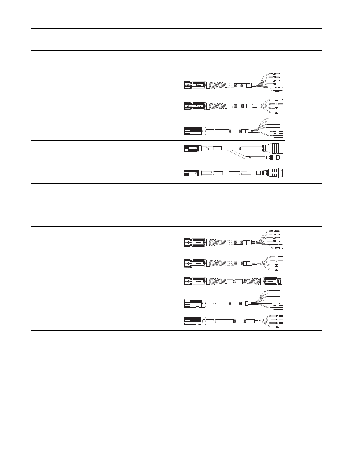
Power/Brake Cable Descriptions (standard, non-flex)
Standard Cable
Cat. No.
2090-CPBM7DF-xxAAxx
2090-CPWM7DF-xxAAxx
2090-XXNPMF-xxSxx
Description
• Drive-end flying-leads (DF)
• Power/brake w ires (PB)
• Drive-end flying-leads (DF)
• Power wire s only (PW)
• Drive-end flying-leads
• Power/brake w ires
• Drive-end bayonet (E2), transition (TR) cable
2090-CPBM4E2-xxTR
• Motor-end threaded DIN (M4)
• Power/brake w ires (PB)
• Drive-end bayonet (E2), transition (TR) cable
2090-CPWM4E2-xxTR
• Motor-end threaded DIN (M4)
• Power wire s only (PW)
(1) Threaded DIN connector (motor end) and bayonet connector for 2090-XXNFMP-Sxx cable.
Power/Brake Cable Descriptions (continuous-flex)
Continuous-flex Cable
Cat. No.
Description
Cable Configuration
Motor/Actuator End Drive End
Motor/Actuator
Connector
SpeedTec DIN
(M7)
(1)
Threaded DIN
(M4)
(1)
Cable Configuration
Motor/Actuator End Drive End
Motor/Actuator
Connector
2090-CPBM7DF-xxAFxx
2090-CPWM7DF-xxAFxx
2090-CPBM7E7-xxAFxx
2090-CPBM4DF-xxAFxx
2090-CPWM4DF-xxAFxx
(1) SpeedTec DIN connector (motor end) and male connector for extending SpeedTec or threaded DIN cable.
• Drive-end flying-leads (DF)
• Power/brake w ires (PB)
• Drive-end flying-leads (DF)
• Power wire s only (PW)
• Drive-end (male) connector, extension (E7)
• Motor-end SpeedTec DIN cable plug (M7)
• Drive-end flying-leads (DF)
• Power/brake w ires (PB)
• Drive-end flying-leads (DF)
• Power wire s only (PW)
(1)
SpeedTec DIN
(M7)
Threaded DIN
(M4)
10 Rockwell Automation Publication GMC-RM007A-EN-P - September 2011
Page 11

Kinetix 7000 Drive Systems
Kinetix 7000 (400V class) Drives with HPK-Series Asynchronous Servo Motors
This section provides system combination information for the Kinetix 7000 (400V class) drives when matched with
HPK-Series™ motors. These motors are available with 460V and 400V windings. Included are motor power/brake and
feedback cable catalog numbers, system performance specifications, and the optimum torque/speed curves.
HPK-Series Motor Cable Combinations (460V motors)
Motor Cat. No. Motor Power Cable Motor Feedback Cable
HPK-B1307C and HPK-B1308C
HPK-B1307E and HPK-B1310C
HPK-B1308E, HPK-B1609E, and HPK-B1613C
HPK-B1611E and HPK-B1613E
HPK-B1815C
HPK-B2010C, HPK-B2010E
HPK-B2212C, HPK-B2510C
(1) Use low-profile connector kit (catalog number 2090-K6CK-D15M) on the drive end. Refer to Required Drive Accessories on page 3.
For cable configuration illustrations and feature descriptions, by catalog number, refer to 2090-Series Motor/Actuator Cables Overview beginning on page 9.
Motor-end connector kits, and panel-mounted breakout components (drive end), are available for motor power/brake and feedback cables. Refer to 2090-Series Motor/Actuator Cables Overview on page 9
Cable len gth xx is in meters. Refer to the Kinetix Motion Accessories Technical Data, publication GMC-TD004
Customer Supplied
, for standard cable lengths.
2090-XXNFMF-Sxx (standard, non-flex)
2090-CFBM4DF-CDAFxx (continuous-flex)
Absolute High-resolution Feedback
(1)
HPK-Series (460V) Performance Specifications with Kinetix 7000 (400V class) Drives
Rotary Motor
HPK-B1307C
HPK-B1308C 59.6 141 (1248) 119.3 262 (2319) 21.6 (28.9) 2099-BM07-S
HPK-B1310C 64.9 155 (1372) 144.0 325 (2876) 23.8 (31.9) 2099-BM08-S
HPK-B1613C 109.8 271 (2398) 217.0 542 (4797) 41.7 (55.9) 2099-BM09-S
HPK-B1815C 153.7 360 (3186) 402.0 850 (7523) 55.9 (74.9) 2099-BM11-S
HPK-B2010C 196.4 482 (4266) 440.0 970 (8585) 75.0 (100.5) 2099-BM11-S
HPK-B2212C 278.0 714 (6319) 524.0 1356 (12,000) 112 (151) 2099-BM12-S
HPK-B2510C 351.0 865 (7656) 526.0 1216 (10,762) 136 (180) 2099-BM12-S
HPK-B1307E
HPK-B1308E 91.4 115 (1018) 190.3 230 (2035) 35.7 (47.8) 2099-BM09-S
HPK-B1609E 124.4 156 (1381) 217.0 270 (2390) 48.4 (64.8) 2099-BM09-S
HPK-B1611E 149.0 183 (1619) 338.4 400 (3540) 57.0 (76.4) 2099-BM11-S
HPK-B1613E 191.0 237 (2097) 440.0 459 (4062) 73.7 (98.8) 2099-BM11-S
HPK-B2010E 254.0 295 (2610) 440.0 500 (4425) 92.0 (125.0) 2099-BM11-S
Performance specification data and curves reflect nominal sys tem performance of a typical system with motor at 40 °C (104 °F) and drive at 50 °C (122 °F) ambient and rated line voltage. For additional
information on ambient and line conditions, refer to Motion Analyzer software, ve rsion 4.7 or later.
Speed, base
rpm
1500
3000
System Continuous
Stall Current
A 0-pk
102.0 112 (991) 113.0 257 (2274) 17.1 (22.9) 2099-BM07-S
81.0 96.0 (849) 146.6 165 (1460) 29.8 (39.9) 2099-BM08-S
System Continuous
Stall Torque
N•m (lb•in)
System Peak
Stall Current
A 0-pk
System Peak
Stall Torque
N•m (lb•in)
Motor Rated
Output
kW (Hp)
Kinetix 7000
(400V class) Drives
.
Rockwell Automation Publication GMC-RM007A-EN-P - September 2011 11
Page 12

Kinetix 7000 Drive Systems
Torque
(N•m)
Torque
(lb•in)
2099-BM07 and HPK-B1307C
0
0
30
60
90
120
150
180
210
240
270
300
Speed (rpm)
250
1000750
0
1500
1250
500
531
1062
2655
1328
1593
1859
2124
2390
797
265
Torque
(N•m)
Torque
(lb•in)
2099-BM08 and HPK-B1310C
0
885
1770
4425
0
50
100
150
200
250
300
350
400
450
500
2213
2655
3098
3540
3982
1328
442
Speed (rpm)
250
1000750
0
1500
1250
500
Torque
(lb•in)
2099-BM11 and HPK-B2010C
0
1770
3540
8850
0
100
200
300
400
500
600
700
800
900
1000
4425
5310
6195
7080
7965
2655
885
Speed (rpm)
250
1000750
0
1500
1250
500
Torque
(N•m)
Torque
(lb•in)
2099-BM11 and HPK-B1815C
0
1770
3540
8850
0
100
200
300
400
500
600
700
800
900
1000
4425
5310
6195
7080
7965
2655
885
Speed (rpm)
250
1000750
0
1500
1250
500
Torque
(N•m)
= Intermittent operating region
= Continuous operating region
= Drive operation with 750V DC (rms) input voltage
Kinetix 7000 (400V class) Drives/HPK-Series (460V) Motor Curves
Torque
(N•m)
Torque
(N•m)
300
270
240
210
180
150
120
600
540
480
420
360
300
240
180
120
2099-BM07 and HPK-B1308C
90
60
30
0
1250
1250
1500
1500
250
0
60
0
0
500
Speed (rpm)
2099-BM09 and HPK-B1613C
250
500
Speed (rpm)
1000750
1000750
2655
2390
2124
1859
1593
1328
1062
797
531
265
0
5310
4749
4248
3717
3186
2655
2124
1593
1062
531
0
Torque
(lb•in)
Torque
(lb•in)
12 Rockwell Automation Publication GMC-RM007A-EN-P - September 2011
Page 13

Kinetix 7000 (400V class) Drives/HPK-Series (460V) Motor Curves (continued)
Torque
(N•m)
Torque
(lb•in)
2099-BM12 and HPK-B2212C
0
0
150
300
450
600
750
900
1050
1200
1350
1500
Speed (rpm)
250
1000750
0
1500
1250
500
2655
5310
13,276
6638
7966
9293
10,621
11,948
3983
1327
Torque
(N•m)
Torque
(lb•in)
2099-BM08 and HPK-B1307E
0
531
1062
2655
0
30
60
90
120
150
180
210
240
270
300
1328
1593
1859
2124
2390
797
265
Speed (rpm)
500
20001500
0
3000
2500
1000
Torque
(N•m)
Torque
(lb•in)
2099-BM09 and HPK-B1609E
0
0
30
60
90
120
150
180
210
240
270
300
Speed (rpm)
500
20001500
0
3000
2500
1000
531
1062
2655
1328
1593
1859
2124
2390
797
265
= Intermittent operating region
= Continuous operating region
= Drive operation with 750V DC (rms) input voltage
Kinetix 7000 Drive Systems
Torque
(N•m)
Torque
(N•m)
1500
1350
1200
1050
900
750
600
450
300
150
300
270
240
210
180
150
120
2099-BM12 and HPK-B2510C
0
1250
2500
1500
3000
250
0
90
60
30
0
0
500
Speed (rpm)
2099-BM09 and HPK-B1308E
500
1000
Speed (rpm)
1000750
20001500
13,276
11,948
10,621
9293
7966
6638
5310
3983
2655
1327
0
2655
2390
2124
1859
1593
1328
1062
797
531
265
0
Torque
(lb•in)
Torque
(lb•in)
Torque
500
(N•m)
450
400
350
300
250
Rockwell Automation Publication GMC-RM007A-EN-P - September 2011 13
200
150
100
50
2099-BM11 and HPK-B1611E
0
500
0
1000
Speed (rpm)
Torque
4425
(lb•in)
3982
3540
3098
2655
2213
1770
1328
885
442
0
2500
20001500
3000
Page 14

Kinetix 7000 Drive Systems
Torque
(N•m)
Torque
(lb•in)
2099-BM11 and HPK-B1613E
0
885
1770
4425
0
50
100
150
200
250
300
350
400
450
500
2213
2655
3098
3540
3982
1328
442
Speed (rpm)
500
20001500
0
3000
2500
1000
= Intermittent operating region
= Continuous operating region
= Drive operation with 750V DC (rms) input voltage
Kinetix 7000 (400V class) Drives/HPK-Series (460V) Motor Curves (continued)
Torque
(N•m)
600
540
480
420
360
300
240
180
120
60
2099-BM11 and HPK-B2010E
0
500
0
1000
Speed (rpm)
20001500
HPK-Series Motor Cable Combinations (400V motors)
Motor Cat. No. Motor Power/Brake Cable Motor Feedback Cable
HPK-E1307C
HPK-E1307E, HPK-E1308E, and HPK-E1310C
HPK-E1609E, HPK-E1611E, HPK-E1613C, and HPK-E1613E
HPK-E1815C and HPK-E2010C
Customer Supplied
2090-XXNFMF-Sxx (standard, non-flex)
2090-CFBM4DF-CDAFxx (continuous-flex)
Absolute High-resolution Feedback
2500
(1)
3000
5310
4749
4248
3717
3186
2655
2124
1593
1062
531
0
Torque
(lb•in)
(1) Use low-profile connector kit (catalog number 2090-K6CK-D15M) or panel-mounted breakout components on drive end. Refer to Required Drive Accessories on page 3
For cable configuration illustrations and feature descriptions, by catalog number, refer to 2090-Series Motor/Actuator Cables Overview beginning on page 9.
Motor-end connector kits, and panel-mounted breakout components (drive end), are available for motor power/brake and feedback cables. Refer to 2090-Series Motor/Actuator Cables Overview on page 9
Cable len gth xx is in meters. Refer to the Kinetix Motion Accessories Technical Data, publication GMC-TD004
, for standard cable lengths.
HPK-Series (400V) Performance Specifications with Kinetix 7000 (400V class) Drives
Rotary Motor
HPK-E1307C
HPK-E1310C 80.0 155 (1372) 200.0 380 (3363) 23.8 (32.4) 2099-BM09-S
HPK-E1613C 133.0 271 (2398) 310.0 625 (5531) 41.7 (55.9) 2099-BM11-S
HPK-E1815C 187.0 360 (3186) 440.0 840 (7434) 55.9 (74.9) 2099-BM11-S
HPK-E2010C 243.0 482 (4266) 440.0 870 (7700) 75.0 (100.5) 2099-BM11-S
HPK-E1307E
HPK-E1308E 112.8 107 (947) 217.7 200 (1770) 33.2 (45.0) 2099-BM09-S
HPK-E1609E 153.7 156 (1381) 356.7 359 (3176) 48.4 (64.9) 2099-BM11-S
HPK-E1611E 185.0 183 (1619) 440.0 430 (3805) 57.0 (76.4) 2099-BM11-S
HPK-E1613E 242.5 237 (2097) 440.0 430 (3805) 73.7 (98.8) 2099-BM11-S
Performance specification data and curves reflect nominal sys tem performance of a typical system with motor at 40 °C (104 °F) and drive at 50 °C (122 °F) ambient and rated line voltage. For additional
information on ambient and line conditions, refer to Motion Analyzer software, ve rsion 4.7 or later.
14 Rockwell Automation Publication GMC-RM007A-EN-P - September 2011
Speed, base
rpm
1500
3000
System Continuous
Stall Current
A 0-pk
58.5 112 (991) 146.6 263 (2327) 17.1 (22.9) 2099-BM08-S
102.0 96.0 (849) 217.0 202 (1788) 29.8 (39.9) 2099-BM09-S
System Continuous
Stall Torque
N•m (lb•in)
System Peak
Stall Current
A 0-pk
System Peak
Stall Torque
N•m (lb•in)
Motor Rated
Output
kW (Hp)
.
Kinetix 7000
(400V class) Drives
Page 15

Kinetix 7000 (400V class) Drives/HPK-Series (400V) Motor Curves
Torque
(N•m)
Torque
(lb•in)
2099-BM08 and HPK-E1307C
0
0
30
60
90
120
150
180
210
240
270
300
Speed (rpm)
250
1000750
0
1500
1250
500
531
1062
2655
1328
1593
1859
2124
2390
797
265
Torque
(N•m)
Torque
(lb•in)
2099-BM09 and HPK-E1310C
0
885
1770
4425
0
50
100
150
200
250
300
350
400
450
500
2213
2655
3098
3540
3982
1328
442
Speed (rpm)
250
1000750
0
1500
1250
500
Torque
(lb•in)
2099-BM11 and HPK-E1613C
0
1770
3540
8850
0
100
200
300
400
500
600
700
800
900
1000
4425
5310
6195
7080
7965
2655
885
Speed (rpm)
250
1000750
0
1500
1250
500
Torque
(N•m)
Torque
(lb•in)
2099-BM11 and HPK-E2010C
0
1770
3540
8850
0
100
200
300
400
500
600
700
800
900
1000
4425
5310
6195
7080
7965
2655
885
Speed (rpm)
250
1000750
0
1500
1250
500
Torque
(N•m)
= Intermittent operating region
= Continuous operating region
= Drive operation with 750V DC (rms) input voltage
Kinetix 7000 Drive Systems
Torque
1000
(N•m)
900
800
700
600
500
400
300
200
100
Torque
250
(N•m)
225
200
175
150
Rockwell Automation Publication GMC-RM007A-EN-P - September 2011 15
125
100
75
50
25
2099-BM11 and HPK-E1815C
0
250
0
2099-BM09 and HPK-E1307E
0
500
0
500
Speed (rpm)
1000
Speed (rpm)
1250
2500
1500
3000
1000750
20001500
8850
7965
7080
6195
5310
4425
3540
2655
1770
885
0
2213
1991
1770
1549
1328
1106
885
664
442
221
0
Torque
(lb•in)
Torque
(lb•in)
Page 16

Kinetix 7000 Drive Systems
Torque
(N•m)
Torque
(lb•in)
2099-BM09 and HPK-E1308E
0
442
885
2213
0
25
50
75
100
125
150
175
200
225
250
1106
1328
1549
1770
1991
664
221
Speed (rpm)
500
20001500
0
3000
2500
1000
Torque
(N•m)
Torque
(lb•in)
2099-BM11 and HPK-E1611E
0
885
1770
4425
0
50
100
150
200
250
300
350
400
450
500
2213
2655
3098
3540
3982
1328
442
Speed (rpm)
500
20001500
0
3000
2500
1000
= Intermittent operating region
= Continuous operating region
= Drive operation with 750V DC (rms) input voltage
Kinetix 7000 (400V class) Drives/HPK-Series (400V) Motor Curves (continued)
Torque
(N•m)
Torque
(N•m)
500
450
400
350
300
250
200
150
100
500
450
400
350
300
250
200
150
100
2099-BM11 and HPK-E1609E
50
0
2500
2500
3000
3000
500
0
50
0
0
1000
Speed (rpm)
2099-BM11 and HPK-E1613E
500
1000
Speed (rpm)
20001500
20001500
4425
3982
3540
3098
2655
2213
1770
1328
885
442
0
4425
3982
3540
3098
2655
2213
1770
1328
885
442
0
Torque
(lb•in)
Torque
(lb•in)
16 Rockwell Automation Publication GMC-RM007A-EN-P - September 2011
Page 17

Kinetix 7000 Drive Systems
IMPORTANT
Kinetix 7000 (400V class) Drives with MP-Series Low Inertia Motors
This section provides system combination information for the Kinetix 7000 (400V class) drives when matched with
MP-Series™ low-inertia motors. Included are motor power/brake and feedback cable catalog numbers, system performance
specifications, and the optimum torque/speed curves.
The MP-Series low-inertia motors on this page are equipped with DIN connectors (specified by 7 in the catalog number) and are
not compatible with cables designed for motors equipped with bayonet connectors (specified by 2 in the catalog number). The
motors with bayonet connectors (for example, MPL-A310P-xx2xAA) are being discontinued and require 2090-XXNxMP (bayonet)
cables. For help with migration or to select bayonet cables, contact your Rockwell Automation® sales representative.
Bulletin MPL Motor Cable Combinations
Motor Cat. No. (400V class) Motor Power/Brake Cable Motor Feedback Cable
MPL-B540K-xx7xAA, MPL-B560F-xx7xAA
MPL-B580F-xx7xAA, MPL-B580J-xx7xAA
MPL-B640F-xx7xAA
MPL-B660F-xx7xAA, MPL-B680D-xx7xAA,
MPL-B960B-xx7xAA, MPL-B980B-xx7xAA
MPL-B680F-xx7xAA, MPL-B860D-xx7xAA
MPL-B880C-xx7xAA
MPL-B880D-xx7xAA
MPL-B960C-xx7xAA, MPL-B960D-xx7xAA,
MPL-B980C-xx7xAA, MPL-B980D-xx7xAA
MPL-B980E-xx7xAA 2090-CPBM7DF-02AAxx (standard, non-flex)
(1) Use low-profile connector kit (catalog number 2090-K6CK-D15M) or panel-mounted breakout components on drive end. Refer to Required Drive Accessories on page 3.
For cable configuration illustrations and feature descriptions, by catalog number, refer to 2090-Series Motor/Actuator Cables Overview beginning on page 9.
Motor-end connector kits, and panel-mounted breakout components (drive end), are available for motor power/brake and feedback cables. Refer to 2090-Series Motor/Actuator Cables Overview on page 9
Cable len gth xx is in meters. Refer to the Kinetix Motion Accessories Technical Data, publication GMC-TD004
2090-CPxM7DF-14AAxx (standard, non-flex)
2090-CPxM7DF-14AFxx (continuous-flex)
2090-CPxM7DF-10AAxx (standard, non-flex)
2090-CPxM7DF-10AFxx (continuous-flex)
2090-CPxM7DF-08AAxx (standard, non-flex)
2090-CPxM7DF-08AFxx (continuous-flex)
2090-CPBM7DF-06AAxx (standard, non-flex)
2090-CPBM7DF-04AAxx (standard, non-flex)
, for standard cable lengths.
2090-CFBM7DF-CEAAxx or
2090-CFBM7DD-CEAAxx (standard, non-flex)
2090-CFBM7DF-CEAFxx or
2090-CFBM7DD-CEAFxx (continuous-flex)
Absolute High-resolution Feedback
(1)
.
Rockwell Automation Publication GMC-RM007A-EN-P - September 2011 17
Page 18

Kinetix 7000 Drive Systems
Bulletin MPL Motor Performance Specifications with Kinetix 7000 (400V class) Drives
Rotary Motor
MPL-B540K 3000 20.4 19.5 (172) 60.0 48.6 (430) 5.4 2099-BM06-S
MPL-B560F 3000 20.6 27.0 (239) 68.0 67.7 (599) 5.5 2099-BM06-S
MPL-B580F 3000 26.0 34.0 (301) 94.0 87.0 (770) 7.1 2099-BM06-S
MPL-B580J 3800 32.0 34.0 (301) 94.0 81.0 (717) 7.9 2099-BM06-S
MPL-B640F 3000 27.8 36.7 (325) 65.0 72.3 (640) 6.1 2099-BM06-S
MPL-B660F 3000 33.0 48.0 (425) 96.0 101 (894) 6.1 2099-BM06-S
MPL-B680D 2000 29.4 62.8 (556) 94.0 154 (1363) 9.3 2099-BM06-S
MPL-B680F 3000 41.5 59.4 (526) 96.0 108 (956) 7.5 2099-BM06-S
MPL-B860D 2000 40.9 83.1 (735) 95.5 152 (1345) 12.5 2099-BM06-S
MPL-B880C 1500 41.1
MPL-B880D 2000
MPL-B960B 1200 36.8 130 (1150) 94.0 231 (2044) 12.7 2099-BM06-S
MPL-B960C 1500 47.6 124 (1097)
MPL-B960D 2000
MPL-B980B 1000 34.6 162 (1434) 94.0 278 (2460) 15.2 2099-BM06-S
MPL-B980C 1500
MPL-B980D 2000
MPL-B980E 2750 105 141 (1250) 218 237 (2100) 13.0 2099-BM09-S
Performance specification data and curves reflect nominal sys tem performance of a typical system with motor at 40 °C (104 °F) and drive at 50 °C (122 °F) ambient and rated line voltage. For additional
information on ambient and line conditions, refer to Motion Analyzer software, ve rsion 4.7 or later.
Speed, max
rpm
System Continuous
Stall Current
A 0-pk
57.0 92.5 (818)
58.0 110 (973) 2099-BM07-S
57.0 100 (885) 96.0 171 (1513)
60.6 124 (1097)
57.0 131 (1159) 96.0 198 (1752)
59.0 158 (1398)
57.0 113 (1000) 96.0 183 (1619)
68.4
System Continuous
Stall Torque
N•m (lb•in)
108 (956) 96.0 200 (1796)
109 (965) 97.5 203 (1770) 2099-BM07-S
148 (1310) 113 213 (1885) 2099-BM07-S
158 (1398) 140 259 (2292) 2099-BM08-S
System Peak
Stall Current
A 0-pk
96.0 147 (1301) 12.6
96.0 184 (1628)
113 209 (1850) 2099-BM07-S
125 226 (2000) 2099-BM08-S
113 201 (1779) 2099-BM07-S
125 223 (1973) 2099-BM08-S
113 227 (2009) 2099-BM07-S
140 270 (2389) 2099-BM08-S
System Peak
Stall Torque
N•m (lb•in)
Motor Rated
Output
kW
12.6
14.8
15.0
16.8
18.6
Kinetix 7000
(400V class) Drives
2099-BM06-S
2099-BM06-S
2099-BM06-S
2099-BM06-S
2099-BM06-S
2099-BM06-S
18 Rockwell Automation Publication GMC-RM007A-EN-P - September 2011
Page 19

Kinetix 7000 (400V class) Drives/MP-Series Low Inertia Motor Curves
Torque
(N•m)
Torque
(lb•in)
0
0
10
20
30
50
40
88.5
177
265
354
2099-BM06 and MPL-B540K
442
Speed (rpm)
0
2000
4000
30001000
Torque
(N•m)
Torque
(lb•in)
2099-BM06 and MPL-B560F
70
60
50
40
30
20
10
0
619
531
442
354
265
177
88.5
0
Speed (rpm)
500
1000
1500 200002500 3000
Torque
(N•m)
Torque
(lb•in)
0
0
20
40
60
100
80
177
354
531
708
885
2099-BM06 and MPL-B580F
Speed (rpm)
500 1000 1500 20000 2500 3000
Torque
(N•m)
Torque
(lb•in)
Speed (rpm)
1000
2000
0
0
0
3000
20
40
60
100
80
4000
177
354
531
708
885
2099-BM06 and MPL-B580J
Torque
(N•m)
Torque
(lb•in)
Speed (rpm)
0
0
20
40
60
80
177
354
531
708
500 1000 1500 20000 2500 3000
2099-BM06 and MPL-B640F
100
885
= Intermittent operating region
= Continuous operating region
= Drive operation with 400V AC (rms) input voltage
Kinetix 7000 Drive Systems
2099-BM06 and MPL-B660F
120
Torque
(N•m)
100
80
60
Rockwell Automation Publication GMC-RM007A-EN-P - September 2011 19
40
20
0
2500
0
500 1500
1000
Speed (rpm)
2000
1062
885
708
531
354
177
0
3000
Torque
(lb•in)
Page 20

Kinetix 7000 Drive Systems
Torque
(N•m)
Torque
(lb•in)
Speed (rpm)
0 20001000500 1500
160
00
20 177
40 354
60 531
80 708
1416
140 1239
120 1062
100 885
2099-BM06 and MPL-B680D
Torque
(N•m)
Torque
(lb•in)
Speed (rpm)
0 20001000500 1500
160
00
20 177
40 354
60 531
80 708
1416
140 1239
120 1062
100 885
2099-BM06 and MPL-B860D
Torque
(N•m)
Torque
(lb•in)
Speed (rpm)
0 20001000500 1500
160
00
20 177
40 354
60 531
80 708
1416
140 1239
120 1062
100 885
2099-BM07 and MPL-B880D
= Intermittent operating region
= Continuous operating region
= Drive operation with 400V AC (rms) input voltage
Kinetix 7000 (400V class) Drives/MP-Series Low Inertia Motor Curves (continued)
2099-BM06 and MPL-B680F
120
Torque
(N•m)
100
1062
885
Torque
(lb•in)
Torque
(N•m)
250
200
150
100
80
60
40
20
0
2500
0
500 1500
1000
Speed (rpm)
2099-BM07 and MPL-B880C
50
2000
3000
708
531
354
177
0
2213
1770
1328
885
442
Torque
(lb•in)
20 Rockwell Automation Publication GMC-RM007A-EN-P - September 2011
Torque
(N•m)
250
200
150
100
50
0 15001000500 1250750250
0
0
Speed (rpm)
2099-BM06 and MPL-B960B
300
600
Speed (rpm)
900
1200
0
0
2213
1770
1328
885
442
0
0
Torque
(lb•in)
Page 21

Kinetix 7000 (400V class) Drives/MP-Series Low Inertia Motor Curves (continued)
Torque
(N•m)
Torque
(lb•in)
0
2099-BM08 and MPL-B960C
442
885
1328
1770
2213
0
50
100
150
200
250
Speed (rpm)
0 15001000500 1250750250
Torque
(N•m)
Torque
(lb•in)
Speed (rpm)
0
0
50
100
150
200
442
885
1328
1770
2213
250
200
400
600
0 1000
800
2099-BM08 and MPL-B980B
300
2655
Torque
(N•m)
Torque
(lb•in)
0
0
50
100
150
200
442
885
1328
1770
2213
250
2099-BM08 and MPL-B980C
300
2655
Speed (rpm)
250
500
750
0 1250
1000
1500
Torque
(N•m)
Torque
(lb•in)
Speed (rpm)
0
0
50
100
150
200
442
885
1328
1770
2213
250
400
800
1200
0 2000
1600
2099-BM08 and MPL-B980D
300
2655
= Intermittent operating region
= Continuous operating region
= Drive operation with 400V AC (rms) input voltage
Torque
(N•m)
Torque
(lb•in)
0
0
50
100
150
200
442
885
1328
1770
2213
250
2099-BM09 and MPL-B980E
300
2655
Speed (rpm)
500
1000
1500
0 2500
2000
3000
2099-BM08 and MPL-B960D
250
Torque
(N•m)
200
Kinetix 7000 Drive Systems
2213
Torque
(lb•in)
1770
150
100
1328
885
50
0
500
100001500
Speed (rpm)
442
0
2000
Rockwell Automation Publication GMC-RM007A-EN-P - September 2011 21
Page 22

Kinetix 7000 Drive Systems
Kinetix 7000 Drives with MP-Series Medium Inertia Motors
This section provides system combination information for the Kinetix 7000 (400V class) drives when matched with
MP-Series medium-inertia motors. Included are motor power/brake and feedback cable catalog numbers, system
performance specifications, and the optimum torque/speed curves.
Bulletin MPM Motor Cable Combinations
Motor Cat. No. (400V class) Motor Power/Brake Cable Motor Feedback Cable
MPM-B1651F, MPM-B1653C
MPM-B1651M, MPM-B1652E, MPM-B1652F, MPM-B1653E
MPM-B2152C, MPM-B2153B
MPM-B1653F
MPM-B2152F, MPM-B2152M, MPM-B2153E, MPM-B2153F,
MPM-B2154B, MPM-B2154E, MPM-B2154F
(1) Use low-profile connector kit (catalog number 2090-K6CK-D15M) with flying-lead cables on the drive end. Refer to Required Drive Accessories on page 3.
For cable configuration illustrations and feature descriptions, by catalog number, refer to 2090-Series Motor/Actuator Cables Overview beginning on page 9.
Motor-end connector kits, and panel-mounted breakout components (drive end), are available for motor power/brake and feedback cables. Refer to 2090-Series Motor/Actuator Cables Overview on page 9
Cable len gth xx is in meters. Refer to the Kinetix Motion Accessories Technical Data, publication GMC-TD004
2090-CPxM7DF-14AAxx (standard, non-flex)
2090-CPxM7DF-14AFxx (continuous-flex)
2090-CPxM7DF-10AAxx (standard, non-flex)
2090-CPxM7DF-10AFxx (continuous-flex)
2090-CPxM7DF-08AAxx (standard, non-flex)
2090-CPxM7DF-08AFxx (continuous-flex)
, for standard cable lengths.
2090-CFBM7DF-CEAAxx or
2090-CFBM7DD-CEAAxx (standard, non-flex)
2090-CFBM7DF-CEAFxx or
2090-CFBM7DD-CEAFxx (continuous-flex)
Absolute High-resolution Feedback
(1)
.
22 Rockwell Automation Publication GMC-RM007A-EN-P - September 2011
Page 23

Bulletin MPM Motor Performance Specifications with Kinetix 7000 (400V class) Drives
Kinetix 7000 Drive Systems
Rotary Motor
MPM-B1651M 4500 5000 22.46 11.3 (100) 56.8 21.4 (189) 2.50 2099-BM06-S
MPM-B1652E 2250 3500 20.94 21.1 (187) 60.5 48.0 (425) 4.30 2099-BM06-S
MPM-B1652F 3000 4500 28.74 21.1 (187) 84.1 45.0 (398) 4.30 2099-BM06-S
MPM-B1653C 1500 2500 20.05 26.7 (236) 59.2 67.7 (599) 4.60 2099-BM06-S
MPM-B1653E 2250 3500 27.0 26.8 (237) 72.9 62.0 (549) 5.10 2099-BM06-S
MPM-B1653F 3000 4000 34.94 31.0 (274) 94.3 56.1 (496) 5.10 2099-BM06-S
MPM-B2152C 1500 2500 27.40 36.7 (325) 55.4 72.2 (639) 5.60 2099-BM06-S
MPM-B2152F 3000 4500 43.54 34.1 (302)
MPM-B2152M 4500 5000 44.58 34.1 (302) 76.3 52.9 (468) 5.90 2099-BM06-S
MPM-B2153B 1250 2000 24.06 48.0 (425) 60.0 101 (895) 6.80 2099-BM06-S
MPM-B2153E 2250 3000 39.63 47.9 (424)
MPM-B2153F 3000 3800 43.86 45.6 (403)
MPM-B2154B 1250 2000 35.46 62.7 (555)
MPM-B2154E 2250 3000 43.68 55.9 (495)
MPM-B2154F 3000 3300 44.40 56.2 (497) 83.6 87.9 (778) 7.50 2099-BM06-S
Performance specification data and curves reflect nominal sys tem performance of a typical system with motor at 40 °C (104 °F) and drive at 50 °C (122 °F) ambient and rated line voltage. For additional
information on ambient and line conditions, refer to Motion Analyzer software, ve rsion 4.7 or later.
Speed,
base
rpm
Speed,
max
rpm
System Continuous
Stall Current
A 0-pk
System Continuous
Stall Torque
N•m (lb•in)
System Peak
Stall Current
A 0-pk
96.0 70.8 (626)
98.0 72.2 (639) 2099-BM07-S
96.0 98.8 (468)
98.6 101 (895) 2099-BM07-S
96.0 96.6 (855)
98.4 98.9 (875) 2099-BM07-S
96.0 151 (1336)
98.0 154 (1363) 2099-BM07-S
96.0 110 (973)
98.3 112 (991) 2099-BM07-S
System Peak
Stall Torque
N•m (lb•in)
Motor Rated
Output
kW
5.90
7.20
7.20
6.90
7.50
Kinetix 7000
400V-class Drives
2099-BM06-S
2099-BM06-S
2099-BM06-S
2099-BM06-S
2099-BM06-S
Rockwell Automation Publication GMC-RM007A-EN-P - September 2011 23
Page 24

Kinetix 7000 Drive Systems
Torque
(N•m)
Torque
(lb•in)
Speed (rpm)
2099-BM06-S and MPM-B1651M
35.4
70.8
106
142
177
212
0
4.0
8.0
12.0
16.0
20.0
24.0
28.0
248
0
0
3000
5000
40001000
2000
Torque
(N•m)
Torque
(lb•in)
0
0
10
20
30
50
40
88.5
177
265
354
442
2099-BM06-S and MPM-B1652F
Speed (rpm)
0
3000
5000
40001000
2000
Torque
(N•m)
Torque
(lb•in)
Speed (rpm)
2099-BM06-S and MPM-B1653E
88.5
177
265
354
442
531
0
10.0
20.0
30.0
40.0
50.0
60.0
70.0
619
0
4000
3000
1000
2000
0
= Intermittent operating region
= Continuous operating region
= Drive operation with 400V AC (rms) input voltage
Kinetix 7000 (400V class) Drives/MP-Series Medium Inertia Motor Curves
50
Torque
(N•m)
40
2099-BM06-S and MPM-B1652E
442
354
Torque
(lb•in)
Torque
(N•m)
30
20
10
70.0
60.0
50.0
40.0
30.0
20.0
10.0
265
177
88.5
0
1500
3000
2000500
1000
0
Speed (rpm)
2099-BM06-S and MPM-B1653C
0
0
1000
2000
Speed (rpm)
2500
4000
3000
0
619
Torque
(lb•in)
531
442
354
265
177
88.5
0
Torque
(N•m)
24 Rockwell Automation Publication GMC-RM007A-EN-P - September 2011
70.0
60.0
50.0
40.0
30.0
20.0
10.0
2099-BM06-S and MPM-B1653F
0
1000
0
2000
Speed (rpm)
3000
4000
619
531
442
354
265
177
88.5
0
Torque
(lb•in)
Page 25

Kinetix 7000 (400V class) Drives/MP-Series Medium Inertia Motor Curves (continued)
Torque
(N•m)
Torque
(lb•in)
0
0
20
40
60
100
80
177
354
531
708
885
2099-BM06-S and MPM-B2152C
Speed (rpm)
500
1000 1500 20000 2500
3000
Torque
(N•m)
Torque
(lb•in)
Speed (rpm)
2099-BM06-S and MPM-B2152M
88.5
177
265
354
442
531
0
10.0
20.0
30.0
40.0
50.0
60.0
70.0
619
0
0
3000
5000
40001000
2000
Torque
(N•m)
Torque
(lb•in)
Speed (rpm)
133
265
398
531
664
796
0
15
30
45
60
75
90
105
929
0
500
1000 1500 20000 2500
3000
2099-BM07-S and MPM-B2153E
= Intermittent operating region
= Continuous operating region
= Drive operation with 400V AC (rms) input voltage
2099-BM07-S and MPM-B2152F
100
Torque
(N•m)
80
Kinetix 7000 Drive Systems
885
Torque
(lb•in)
708
Torque
(N•m)
60
40
20
105
531
354
177
0
0
2099-BM06-S and MPM-B2153B
90
75
60
45
30
15
0
500
0
2000
Speed (rpm)
1000
Speed (rpm)
3000
40001000
1500
5000
2000
0
929
Torque
(lb•in)
796
664
531
398
265
133
0
2099-BM07-S and MPM-B2153F
100
Torque
(N•m)
80
60
40
Rockwell Automation Publication GMC-RM007A-EN-P - September 2011 25
20
0
1000
0
2000
Speed (rpm)
3000
4000
885
708
531
354
177
0
Torque
(lb•in)
Page 26

Kinetix 7000 Drive Systems
Torque
(N•m)
Torque
(lb•in)
Speed (rpm)
221
442
664
885
1106
1327
0
25
50
75
100
125
150
175
1549
0
2000
1500
500
1000
0
2099-BM07-S and MPM-B2154B
Torque
(N•m)
Torque
(lb•in)
0
0
20
40
60
100
80
177
354
531
708
885
2099-BM06-S and MPM-B2154F
Speed (rpm)
4000
3000
1000
2000
0
= Intermittent operating region
= Continuous operating region
= Drive operation with 400V AC (rms) input voltage
Kinetix 7000 (400V class) Drives/MP-Series Medium Inertia Motor Curves (continued)
2099-BM07-S and MPM-B2154E
125
Torque
(N•m)
100
1106
885
Torque
(lb•in)
75
50
25
0
500
1000 1500 20000 2500
Speed (rpm)
664
442
221
0
3000
26 Rockwell Automation Publication GMC-RM007A-EN-P - September 2011
Page 27

Kinetix 7000 Drive Systems
Kinetix 7000 Drives with RDD-Series Direct Drive Motors
This section provides system combination information for the Kinetix 7000 (400V class) drives when matched with
RDD-Series™ direct-drive motors. Included are motor power/brake and feedback cable catalog numbers, system
performance specifications, and the optimum torque/speed curves.
Bulletin RDB Motor Cable Combinations
Motor Cat. No. (400V class) Motor Power/Brake Cable Motor Feedback Cable
RDB-B2152C 2090-CPWM7DF-12AAxx (standard, non-flex)
RDB-B2153C, RDB-B29036
RDB-B29029, RDB-B41016, RDB-B41024
RDB-B29039, RDB-B41018, RDB-B41026, RDB-B41035 2090-CPBM7DF-06AAxx (standard, non-flex)
(1) Use low-profile feedback module (catalog number 2090-K7CK-KENDAT). Refer to Required Drive Accessories on page3.
For cable configuration illustrations and feature descriptions, by catalog number, refer to 2090-Series Motor/Actuator Cables Overview beginning on page 9.
Motor-end connector kits (drive end) are available for motor power/brake and feedback cables. Refer to 2090-Series Motor/Actuator Cables Overview on page 9
Cable len gth xx is in meters. Refer to the Kinetix Motion Accessories Technical Data, publication GMC-TD004
2090-CPWM7DF-10AAxx (standard, non-flex)
2090-CPWM7DF-10AFxx (continuous-flex)
2090-CPWM7DF-08AAxx (standard, non-flex)
2090-CPWM7DF-08AFxx (continuous-flex)
, for standard cable lengths.
2090-XXNFMF-Sxx (standard, non-flex)
2090-CFBM7DF-CDAFxx (continuous-flex)
Absolute High-resolution Feedback
.
(1)
Bulletin RDB Motor Performance Specifications with Kinetix 7000 (400V class) Drives
Speed,
Rotary Motor
RDB-B2152C 1500 2125 23.5 43.4 (384) 63.2 111 (982) 6.41 2099-BM06-S
RDB-B2153C 1500 2250 29.4 51.5 (456) 82.6 137 (1212) 5.87 2099-BM06-S
RDB-B29029 750 1200 36.2 97.5 (863)
RDB-B29036 375 750 26.0 140 (1239) 84.9 318 (2814) 5.49 2099-BM06-S
RDB-B29039 750 1000 52.7 122 (1080) 147 268 (2372) 4.41 2099-BM08-S
RDB-B41016 375 700 33.2 183 (1619) 95.5 339 (3000) 4.83 2099-BM06-S
RDB-B41018 625 700 51.3 183 (1619)
RDB-B41024 200 365 31.5 330 (2929) 95.5 690 (6107) 7.29 2099-BM06-S
RDB-B41026 375 600 52.0 308 (2726)
RDB-B41035 250 490 52.6 425 (3761)
Performance specification data and curves reflect nominal sys tem performance of a typical system with motor at 40 °C (104 °F) and drive at 50 °C (122 °F) ambient and rated line voltage. For additional
information on ambient and line conditions, refer to Motion Analyzer software, ve rsion 4.7 or later.
base
rpm
Speed,
max
rpm
System Continuous
Stall Current
A 0-pk
System Continuous
Stall Torque
N•m (lb•in)
System Peak
Stall Current
A 0-pk
96.0 193 (1708)
111 214 (1894) 2099-BM07-S
113 299 (2646)
140 339 (3000) 2099-BM08-S
147 626 (5540)
218 688 (6089) 2099-BM09-S
147 897 (7939)
218 1050 (9293) 2099-BM09-S
System Peak
Stall Torque
N•m (lb•in)
Motor Rated
Output
kW
4.05
4.83
7.29
8.69
Kinetix 7000
(400V class) Drives
2099-BM06-S
2099-BM07-S
2099-BM08-S
2099-BM08-S
Rockwell Automation Publication GMC-RM007A-EN-P - September 2011 27
Page 28

Kinetix 7000 Drive Systems
Torque
(N•m)
Torque
(lb•in)
0
0
25
50
75
125
100
221
442
664
885
1106
2099-BM06-S and RDB-B2152C
Speed (rpm)
0
1000
2000
1500500
2500
Torque
(N•m)
Torque
(lb•in)
0
0
50
100
150
250
200
442
885
1327
1770
2212
2099-BM07-S and RDB-B29029
Speed (rpm)
250
500 750 10000 1250
1500
Torque
(N•m)
Torque
(lb•in)
0
0
60
120
180
300
240
531
1062
1593
2124
2655
2099-BM08-S and RDB-B29039
Speed (rpm)
0
400
800
600200
1000
Peak curve represents
480V and 400V inputs
= Intermittent operating region
= Continuous operating region
= Drive operation with 400V AC (rms) input voltage
Kinetix 7000 (400V class) Drives with RDD-Series Direct Drive Motor Curves
140
Torque
(N•m)
120
2099-BM06-S and RDB-2153C
1239
1062
Torque
(lb•in)
Torque
(N•m)
100
350
300
250
200
150
100
885
80
60
40
20
0
0
2099-BM06-S and RDB-B29036
50
1500500
1000
Speed (rpm)
2000
2500
70
531
354
177
0
3098
2655
2212
1770
1327
885
442
8
Torque
(lb•in)
1000
1000
0
3098
2655
2212
1770
1327
885
442
0
Torque
(lb•in)
0
0
2099-BM06-S and RDB-B41016
350
Torque
(N•m)
300
250
200
150
100
50
0
0
600200
400
Speed (rpm)
600200
400
Speed (rpm)
800
800
28 Rockwell Automation Publication GMC-RM007A-EN-P - September 2011
Page 29

Kinetix 7000 (400V class) Drives with RDD-Series Direct Drive Motor Curves (continued)
Torque
(N•m)
Torque
(lb•in)
Speed (rpm)
442
885
1327
1770
2212
2655
0
50
100
150
200
250
300
350
3098
0
0
400
800
600200
1000
2099-BM08-S and RDB-B41018
Torque
(N•m)
Torque
(lb•in)
0
0
150
300
450
750
600
1327
2655
39
83
5310
6638
2099-BM09-S and RDB-B41026
Speed (rpm)
100
200 300 4000 500
600
Torque
(N•m)
Torque
(lb•in)
0
0
250
500
750
1250
1000
2212
4425
6638
8851
11,063
2099-BM09-S and RDB-B41035
Speed (rpm)
0
200
400
300100
500
= Intermittent operating region
= Continuous operating region
= Drive operation with 400V AC (rms) input voltage
2099-BM06-S and RDB-B41024
750
Torque
(N•m)
600
Kinetix 7000 Drive Systems
6638
Torque
(lb•in)
5310
450
300
150
3983
2655
1327
0
0
300100
200
Speed (rpm)
400
0
500
Rockwell Automation Publication GMC-RM007A-EN-P - September 2011 29
Page 30

Kinetix 7000 Drive Systems
Additional Resources
These documents contain additional information concerning related products from Rockwell Automation.
Resource Description
Kinetix Motion Control Selection Guide, publication GMC-SG001
Kinetix Rotary Motion Specifications, publication GMC-TD001
Kinetix Linear Motion Specifications, publication GMC-TD002
Kinetix Servo Drives Specifications, publication GMC-TD003
Kinetix Motion Accessories Specifications, publication GMC-TD004
Kinetix 6000 and Kinetix 6200/6500 Drive Systems Design Guide,
publication GMC-RM003
Kinetix 300/350 Drive Systems Design Guide, publication GMC-RM004
Kinetix 3 Drive Systems Design Guide, publication GMC-RM005
Kinetix 2000 Drive Systems Design Guide, publication GMC-RM006
Ultra™ 3000 Drive Systems Design Guide, publication GMC-RM008
Kinetix 6200 and Kinetix 6500 Safe Speed Monitoring Servo Drives Safety
Reference Manual, publication 2094-RM001
Kinetix 6200 and Kinetix 6500 Safe Torque-off Servo Drives Safety
Reference Manual, publication 2094-RM002
Kinetix Safe-off Feature Safety Reference Manual,
publication GMC-RM002
System Design for Control of Electrical Noise Reference Manual,
publication GMC-RM001
EMC Noise Management DVD, publication GMC-SP004
ControlLogix Selection Guide, publication 1756-SG001
CompactLogix Selection Guide, publication 1769-SG001
Integrated Architecture Recommended Literature Reference Manual,
publication IASIMP-RM001
Industrial Ethernet Media Brochure, publication 1585-BR001
Motion Analyzer software download from
http://www.ab.com/motion/software/analyzer.html
Rockwell Automation Configuration and Selection Tools,
website http://w ww.ab.com
Overview of Kinetix servo drives, motors, actuators, and motion accessories designed to help make
initial decisions for the motion control products best suited for your system requirements.
Product specifications for MP-Series (Bulletin MPL, MPM, MPF, MPS), TL-Series™, RDD-Series, and
HPK-Series rotary motors.
Product specifications for Bulletin MPAS and MPMA linear stages, Bulletin MPAR, MPAI, and TLAR
electric cylinders, and LDC-Series™ and LDL-Series™ linear motors.
Product specifications for Kinetix Integrated Motion over the EtherNet/IP network, Integrated Motion
over SERCOS interface, EtherNet/IP networking, and component servo drive families.
Product specifications for Bulletin 2090 motor and interface cables, low-profile connector kits, drive
power components, and other servo drive accessory items.
System design guide to determine and select the required (drive specific) drive module, power
accessory, connector kit, motor cable, and interface cable catalog numbers for your drive and motor/
actuator motion control system. Included are system performance specifications and torque/speed
curves (rotary motion) and force/velocity curves (linear motion) for your motion application.
Information on wiring, configuring, and troubleshooting the safe-speed features of your Kinetix 6200
and Kinetix 6500 drives.
Information on wiring, configuring, and troubleshooting the safe torque-off features of your
Kinetix 6200 and Kinetix 6500 drives.
Information on wiring and troubleshooting your Kinetix 6000 and Kinetix 7000 servo drives with the
safe-off feature.
Information, examples, and techniques designed to minimize system failures caused by electrical noise.
Information to determine which ControlLogix controller fits your application and the product
specifications to help design a ControlLogix system and select the appropriate components.
Information to determine which CompactLogix™ controller fits your application and the product
specifications to help design a CompactLogix system and select the appropriate components.
This document provides lists of technical publications for Integrated Architecture™ products. These lists
are not all-inclusive, but they do include the most-commonly accessed publications for the related
products.
Information to determine which Bulletin 1585 Ethernet cable fits your application and the product
specifications to help select the appropriate components.
Comprehensive motion application sizing tool used for analysis, optimization, selection, and validation
of your Kinetix Motion Control system.
Online product selection and system configuration tools, including AutoCad (DXF) drawings.
You can view or download publications at http://www.rockwellautomation.com/literature/
. To order paper copies of
technical documentation, contact your local Allen-Bradley distributor or Rockwell Automation sales representative.
30 Rockwell Automation Publication GMC-RM007A-EN-P - September 2011
Page 31

Notes:
Kinetix 7000 Drive Systems
Rockwell Automation Publication GMC-RM007A-EN-P - September 2011 31
Page 32

Rockwell Otomasyon Ticaret A.Ş., Kar Plaza İş Merkezi E Blok Kat:6 34752 İçerenköy, İstanbul, Tel: +90 (216) 5698400
Power, Control and Information Solutions Headquarters
Americas: Rockwell Automation, 1201 South Second Street, Milwaukee, WI 53204-2496 USA, Tel: (1) 414.382.2000, Fax: (1) 414.382.4444
Europe/Middle East/Africa: Rockwell Automation NV, Pegasus Park, De Kleetlaan 12a, 1831 Diegem, Belgium, Tel: (32) 2 663 0600, Fax: (32) 2 663 0640
Asia Pacic: Rockwell Automation, Level 14, Core F, Cyberport 3, 100 Cyberport Road, Hong Kong, Tel: (852) 2887 4788, Fax: (852) 2508 1846
www.rockwel lautomation.com
Important Information
Solid-state equipment has operational characteristics differing from those of electromechanical equipment. Safety
Guidelines for the Application, Installation and Maintenance of Solid State Controls (publication SGI-1.1
your local Rockwell Automation sales office or online at http://www.rockwellautomation.com/literature/
important differences between solid-state equipment and hard-wired electromechanical devices. Because of this difference,
and also because of the wide variety of uses for solid-state equipment, all persons responsible for applying this equipment
must satisfy themselves that each intended application of this equipment is acceptable.
In no event will Rockwell Automation, Inc. be responsible or liable for indirect or consequential damages resulting from the
use or application of this equipment.
The examples and diagrams in this publication are included solely for illustrative purposes. Because of the many variables
and requirements associated with any particular installation, Rockwell Automation, Inc. cannot assume responsibility or
liability for actual use based on the examples and diagrams.
No patent liability is assumed by Rockwell Automation, Inc. with respect to use of information, circuits, equipment, or
software described in this manual.
Reproduction of the contents of this manual, in whole or in part, without written permission of Rockwell Automation,
Inc., is prohibited.
available from
) describes some
Documentation Feedback
Your comments will help us serve your documentation needs better. If you have any suggestions on how to improve this
document, complete this form, publication
Allen-Bradley, CompactLogix, ControlLogix, Encompass, HPK-Series, Integrated Architecture, Kinetix, LDC-Series, LDL-Series, LISTEN. THINK. SOLVE., MP-Series, RDD-Series, RSLogix, TL-Series,
Rockwell Software, and Rockwell Automation are trademarks of Rockwell Automation, Inc.
Trademarks not belong ing to Rockwell Automation are property of their respective companies.
RA-DU002, available at http://www.rockwellautomation.com/literature/.
Publication GMC-RM007A-EN-P - September 2011
Supersedes Publication GMC-SG001Q-EN-P - April 2011 Copyright © 2011 Rockwell Auto mation, Inc. All rights reserved. Pr inted in the U.S.A.
 Loading...