

Page 1

User Manual
Kinetix 7000 High Power Servo Drive
Catalog Numbers 2099-BM06-S, 2099-BM07-S, 2099-BM08-S, 2099-BM09-S, 2099-BM10-S, 2099-BM11-S, 2099-BM12-S
Page 2
Important User Information
IMPORTANT
Solid-state equipment has operational characteristics differing from those of electromechanical equipment. Safety
Guidelines for the Application, Installation and Maintenance of Solid State Controls (publication SGI-1.1
your local Rockwell Automation® sales office or online at http://www.rockwellautomation.com/literature/
important differences between solid-state equipment and hard-wired electromechanical devices. Because of this difference,
and also because of the wide variety of uses for solid-state equipment, all persons responsible for applying this equipment
must satisfy themselves that each intended application of this equipment is acceptable.
In no event will Rockwell Automation, Inc. be responsible or liable for indirect or consequential damages resulting from the
use or application of this equipment.
The examples and diagrams in this manual are included solely for illustrative purposes. Because of the many variables and
requirements associated with any particular installation, Rockwell Automation, Inc. cannot assume responsibility or
liability for actual use based on the examples and diagrams.
No patent liability is assumed by Rockwell Automation, Inc. with respect to use of information, circuits, equipment, or
software described in this manual.
Reproduction of the contents of this manual, in whole or in part, without written permission of Rockwell Automation,
Inc., is prohibited.
Throughout this manual, when necessary, we use notes to make you aware of safety considerations.
available from
) describes some
WARNING: Identifies information about practices or circumstances that can cause an explosion in a hazardous environment,
which may lead to personal injury or death, property damage, or economic loss.
ATTENTION: Identifies information about practices or circumstances that can lead to personal injury or death, property
damage, or economic loss. Attentions help you identify a hazard, avoid a hazard, and recognize the consequence.
SHOCK HAZARD: Labels may be on or inside the equipment, for example, a drive or motor, to alert people that dangerous
voltage may be present.
BURN HAZARD: Labels may be on or inside the equipment, for example, a drive or motor, to alert people that surfaces may
reach dangerous temperatures.
Identifies information that is critical for successful application and understanding of the product.
Allen-Bradley, CompactLogix, ControlFlash, ControlLogix, DriveExplorer, Kinetix, RSLogix 5000, Rockwell Sof tware, Rockwell Automation, and TechConnect are trademarks of Rockwell Automation, Inc.
Trademarks not belong ing to Rockwell Automation are property of their respective companies.
Page 3

Summary of Changes
This manual contains new and updated information. Changes throughout this
revision are marked by change bars, as shown to the right of this paragraph.
New and Updated Information
This table contains the changes made to this revision.
Topic Page
Updated the Additional Resources with updated and new publications. 9
Updated the Typical System Diagrams to include updated catalog numbers for
Bulletin MPL motors, Bulletin MPM motors, and regenerative power supplies.
Added the Using Motion Analyzer to Determine Heat Dissipation information to the
Enclosure Selection section.
Added the mounting information from Chapter 3 - Mount the Kinetix 7000 Drive
System, to Chapter 2 - Install the Kinetix 7000 Drive System and removed Chapter 3.
Updated the Kinetix 7000 Front Panel Connectors and Displays, Kinetix 7000 Top
Panel Connectors and Switches, and Kinetix 7000 Bottom Panel Connectors
illustrations and tables for clarity.
Updated the IOD connector pinouts in the Hardware Enable, Home and Positive and
Negative Overtravel circuit diagrams.
Added information on Reading Analog Input Voltage Values. 61
Updated information on configuring the General Purpose I/O regenerative power
supply OK signal.
Added Figure 41 Safe-Off, Motion-allowed Jumper. 65
Updated the information in the Setting the Ground Jumper in Ungrounded Power
Configurations section.
Updated the Wire the Kinetix 7000 Drive Connectors section. 88
Added Flying-lead Feedback Cable Pinouts for the new 2090-XXNFMF-Sxx and 2090-
CFBMxDF-CDAFxx Feedback Cable.
Added illustrations to the Wire Feedback and I/O Connectors section. 95
Updated the information on External Shunt Module Connections to reflect
availability of certain shunt modules.
Updated the Node Addressing Examples to reflect current topologies. 108
Updated the steps and images in the Configure the Logix SERCOS interface Module
section to reflect the current software release.
Added the Configure Drive Parameters and System Variables section. 134
Added an explanation for the Drive Overtemperature Fault (E23) to the list of Error
Codes.
Updated the Specifications and Dimensions section to reflect current data and
specifications.
Added Korean Registration of Broadcasting and Communications Equipment
certification to the Certifications table.
Added the new External Shunt Modules section to Appendix A. 156
Updated the Interconnect Diagrams to reflect new cables and corrected connections
information.
13
24
39
42
55
64
78
95
101
110
140
150
154
161
Rockwell Automation Publication 2099-UM001D-EN-P - December 2012 3
Page 4

Summary of Changes
Notes:
4 Rockwell Automation Publication 2099-UM001D-EN-P - December 2012
Page 5

Table of Contents
Preface
Start
Install the Kinetix 7000 Drive System
About This Publication. . . . . . . . . . . . . . . . . . . . . . . . . . . . . . . . . . . . . . . . . . . . . 9
Who Should Use This Manual . . . . . . . . . . . . . . . . . . . . . . . . . . . . . . . . . . . . . . 9
Conventions Used in This Manual . . . . . . . . . . . . . . . . . . . . . . . . . . . . . . . . . . 9
Additional Resources . . . . . . . . . . . . . . . . . . . . . . . . . . . . . . . . . . . . . . . . . . . . . . . 9
Chapter 1
About the Drive System . . . . . . . . . . . . . . . . . . . . . . . . . . . . . . . . . . . . . . . . . . 12
Typical Drive System Diagrams . . . . . . . . . . . . . . . . . . . . . . . . . . . . . . . . . . . 13
Catalog Number Explanation . . . . . . . . . . . . . . . . . . . . . . . . . . . . . . . . . . . . . 18
Agency Compliance . . . . . . . . . . . . . . . . . . . . . . . . . . . . . . . . . . . . . . . . . . . . . . 18
CE Requirements - System without LIM . . . . . . . . . . . . . . . . . . . . . . . 19
CE Requirements - System with LIM . . . . . . . . . . . . . . . . . . . . . . . . . . 20
CE Requirements - System with DC Common Bus through 8720MC-
RPS . . . . . . . . . . . . . . . . . . . . . . . . . . . . . . . . . . . . . . . . . . . . . . . . . . . . . . . . . 20
Chapter 2
System Design Guidelines. . . . . . . . . . . . . . . . . . . . . . . . . . . . . . . . . . . . . . . . . 22
System Mounting Requirements. . . . . . . . . . . . . . . . . . . . . . . . . . . . . . . 22
Transformer Selection . . . . . . . . . . . . . . . . . . . . . . . . . . . . . . . . . . . . . . . . 22
Circuit Breaker/Fuse Selection . . . . . . . . . . . . . . . . . . . . . . . . . . . . . . . . 23
Enclosure Selection . . . . . . . . . . . . . . . . . . . . . . . . . . . . . . . . . . . . . . . . . . . 24
Minimum Clearance Requirements . . . . . . . . . . . . . . . . . . . . . . . . . . . . 27
Minimizing Electrical Noise. . . . . . . . . . . . . . . . . . . . . . . . . . . . . . . . . . . . . . . 28
Bonding Modules . . . . . . . . . . . . . . . . . . . . . . . . . . . . . . . . . . . . . . . . . . . . 28
Bonding Multiple Subpanels . . . . . . . . . . . . . . . . . . . . . . . . . . . . . . . . . . 30
Establish Noise Zones . . . . . . . . . . . . . . . . . . . . . . . . . . . . . . . . . . . . . . . . 30
Cable Categories for Kinetix 7000 Systems . . . . . . . . . . . . . . . . . . . . . 35
Noise Reduction Guidelines for Drive Accessories. . . . . . . . . . . . . . . 36
Mount the Kinetix 7000 Drive . . . . . . . . . . . . . . . . . . . . . . . . . . . . . . . . . . . . 39
Kinetix 7000 Connector Data
Chapter 3
Locate and Identify Connectors and Indicators . . . . . . . . . . . . . . . . . . . . . 42
Digital and Analog Input/Output (IOD) Connector Pinout. . . . . 45
General Purpose I/O (GPIO) Terminal Block Connections . . . . . 46
General Purpose Relay (GPR) Terminal Block Connections . . . . . 46
Motor Feedback (MF) Connector Pinouts . . . . . . . . . . . . . . . . . . . . . 47
Auxiliary Feedback (AF) Connector Pinouts . . . . . . . . . . . . . . . . . . . 49
Safe-off (SO) Terminal Block Connections. . . . . . . . . . . . . . . . . . . . . 50
Control Power (CP) Terminal Block Connections. . . . . . . . . . . . . . 51
Power Terminal Block (PTB) Connections. . . . . . . . . . . . . . . . . . . . . 51
Rockwell Automation Publication 2099-UM001D-EN-P - December 2012 5
Page 6

Table of Contents
Control Signal Specifications . . . . . . . . . . . . . . . . . . . . . . . . . . . . . . . . . . . . . . 54
Digital Inputs (IOD Connector). . . . . . . . . . . . . . . . . . . . . . . . . . . . . . . 54
Analog Inputs (IOD Connector) . . . . . . . . . . . . . . . . . . . . . . . . . . . . . . 60
Analog Outputs (IOD Connector). . . . . . . . . . . . . . . . . . . . . . . . . . . . . 62
General Purpose I/O (GPIO Connector). . . . . . . . . . . . . . . . . . . . . . . 63
General Purpose Relay (GPR Connector). . . . . . . . . . . . . . . . . . . . . . . 64
SERCOS Connections. . . . . . . . . . . . . . . . . . . . . . . . . . . . . . . . . . . . . . . . 65
Safe-off (SO Connector) . . . . . . . . . . . . . . . . . . . . . . . . . . . . . . . . . . . . . . 65
Control Power Specifications. . . . . . . . . . . . . . . . . . . . . . . . . . . . . . . . . . . . . . 65
Motor (MF) and Auxiliary Feedback (AF) Connections . . . . . . . . . . . . . 66
Motor and Auxiliary Feedback Specifications . . . . . . . . . . . . . . . . . . . 66
Chapter 4
Connect the Kinetix 7000 Drive
System
Basic Wiring Requirements . . . . . . . . . . . . . . . . . . . . . . . . . . . . . . . . . . . . . . . 71
Building Your Own Motor Cables . . . . . . . . . . . . . . . . . . . . . . . . . . . . . 72
Shielded Motor Cable. . . . . . . . . . . . . . . . . . . . . . . . . . . . . . . . . . . . . . . . . 72
Required Cable Types. . . . . . . . . . . . . . . . . . . . . . . . . . . . . . . . . . . . . . . . . 72
Cable Sizes . . . . . . . . . . . . . . . . . . . . . . . . . . . . . . . . . . . . . . . . . . . . . . . . . . . 73
Conduit . . . . . . . . . . . . . . . . . . . . . . . . . . . . . . . . . . . . . . . . . . . . . . . . . . . . . 73
General Wire Guidelines . . . . . . . . . . . . . . . . . . . . . . . . . . . . . . . . . . . . . . 74
Routing the Power and Signal Cables. . . . . . . . . . . . . . . . . . . . . . . . . . . 74
Determine the Input Power Configuration . . . . . . . . . . . . . . . . . . . . . . . . . 75
Grounded Power Configurations . . . . . . . . . . . . . . . . . . . . . . . . . . . . . . 75
Power Distribution Systems Without a Ground Reference . . . . . . . 77
Setting the Ground Jumper in Ungrounded Power Configurations . . . 78
Removing the Ground Jumper on 2099-BM06-S, 2099-BM07-S, and
2099-BM08-S Drives . . . . . . . . . . . . . . . . . . . . . . . . . . . . . . . . . . . . . . . . . 79
Removing the Ground Wires on 2099-BM09-S and 2099-BM10-S
Drives . . . . . . . . . . . . . . . . . . . . . . . . . . . . . . . . . . . . . . . . . . . . . . . . . . . . . . . 80
Removing the Ground Wires on 2099-BM11-S and 2099-BM12-S
Drives . . . . . . . . . . . . . . . . . . . . . . . . . . . . . . . . . . . . . . . . . . . . . . . . . . . . . . . 80
Grounding the Kinetix 7000 Drive System . . . . . . . . . . . . . . . . . . . . . . . . . 81
Grounding Your System to the Subpanel . . . . . . . . . . . . . . . . . . . . . . . 81
Grounding Multiple Subpanels . . . . . . . . . . . . . . . . . . . . . . . . . . . . . . . . 82
Motor Power Cable Shield Termination. . . . . . . . . . . . . . . . . . . . . . . . 82
MP-Series (Bulletin MPL) Motor Connectors . . . . . . . . . . . . . . . . . . 83
Input Power Wiring Requirements . . . . . . . . . . . . . . . . . . . . . . . . . . . . . . . . 85
Acceptable Cable Types . . . . . . . . . . . . . . . . . . . . . . . . . . . . . . . . . . . . . . . 85
Shielded/Armored Cable. . . . . . . . . . . . . . . . . . . . . . . . . . . . . . . . . . . . . . 85
Contactors . . . . . . . . . . . . . . . . . . . . . . . . . . . . . . . . . . . . . . . . . . . . . . . . . . . 86
Power Wire Specifications. . . . . . . . . . . . . . . . . . . . . . . . . . . . . . . . . . . . . 87
Power Wiring Guidelines . . . . . . . . . . . . . . . . . . . . . . . . . . . . . . . . . . . . . . . . . 88
6 Rockwell Automation Publication 2099-UM001D-EN-P - December 2012
Page 7

Table of Contents
Wire the Kinetix 7000 Drive Connectors . . . . . . . . . . . . . . . . . . . . . . . . . . 88
Wire the Control Power (CP) Connector . . . . . . . . . . . . . . . . . . . . . . 88
Wire AC Input Power . . . . . . . . . . . . . . . . . . . . . . . . . . . . . . . . . . . . . . . . 89
Wire DC Input Power (Common Bus Configurations Only) . . . . 89
Wire the Safe-off (SO) Connector . . . . . . . . . . . . . . . . . . . . . . . . . . . . . 90
Wire the General Purpose Relay (GPR) and General Purpose I/O
(GPIO) Connectors . . . . . . . . . . . . . . . . . . . . . . . . . . . . . . . . . . . . . . . . . . 91
Wire Motor Output Power . . . . . . . . . . . . . . . . . . . . . . . . . . . . . . . . . . . 92
Wire the Motor Brake . . . . . . . . . . . . . . . . . . . . . . . . . . . . . . . . . . . . . . . . 92
Feedback and I/O Cable Connections . . . . . . . . . . . . . . . . . . . . . . . . . . . . . 93
Flying-lead Feedback Cable Pinouts. . . . . . . . . . . . . . . . . . . . . . . . . . . . 94
Wire Feedback and I/O Connectors . . . . . . . . . . . . . . . . . . . . . . . . . . . . . . . 95
Connect Premolded Motor Feedback Cables . . . . . . . . . . . . . . . . . . . 95
Wire Panel-mounted Breakout Board Kits. . . . . . . . . . . . . . . . . . . . . . 96
Wire Low-profile Connectors . . . . . . . . . . . . . . . . . . . . . . . . . . . . . . . . . 98
External Shunt Module Connections . . . . . . . . . . . . . . . . . . . . . . . . . . . . . 101
SERCOS Fiber-optic Cable Connections . . . . . . . . . . . . . . . . . . . . . . . . . 101
Configure and Startup the Kinetix
7000 Drive System
Troubleshoot the Kinetix 7000 Drive
System
Chapter 5
Configure the Drive Modules . . . . . . . . . . . . . . . . . . . . . . . . . . . . . . . . . . . . 106
Node Addressing Examples. . . . . . . . . . . . . . . . . . . . . . . . . . . . . . . . . . . 108
Configure the Logix SERCOS interface Module . . . . . . . . . . . . . . . . . . . 110
Configure the Logix Controller. . . . . . . . . . . . . . . . . . . . . . . . . . . . . . . 110
Configure the SERCOS Module. . . . . . . . . . . . . . . . . . . . . . . . . . . . . . 112
Configure the Motion Group . . . . . . . . . . . . . . . . . . . . . . . . . . . . . . . . 114
Configure the Kinetix 7000 Drive Modules. . . . . . . . . . . . . . . . . . . . 117
Download the Program . . . . . . . . . . . . . . . . . . . . . . . . . . . . . . . . . . . . . . 125
Apply Power to the Drive . . . . . . . . . . . . . . . . . . . . . . . . . . . . . . . . . . . . . . . . 126
Test and Tune the Axes. . . . . . . . . . . . . . . . . . . . . . . . . . . . . . . . . . . . . . . . . . 129
Test the Axes . . . . . . . . . . . . . . . . . . . . . . . . . . . . . . . . . . . . . . . . . . . . . . . 129
Tune the Axes. . . . . . . . . . . . . . . . . . . . . . . . . . . . . . . . . . . . . . . . . . . . . . . 131
Configure Drive Parameters and System Variables . . . . . . . . . . . . . . . . . 134
Tools for Changing Parameters . . . . . . . . . . . . . . . . . . . . . . . . . . . . . . . 134
Chapter 6
Safety Precautions. . . . . . . . . . . . . . . . . . . . . . . . . . . . . . . . . . . . . . . . . . . . . . . 137
Interpret Error Codes and Status Indicators . . . . . . . . . . . . . . . . . . . . . . . 138
Error Codes. . . . . . . . . . . . . . . . . . . . . . . . . . . . . . . . . . . . . . . . . . . . . . . . . 138
Status Indicators . . . . . . . . . . . . . . . . . . . . . . . . . . . . . . . . . . . . . . . . . . . . 143
General System Anomalies. . . . . . . . . . . . . . . . . . . . . . . . . . . . . . . . . . . . . . . 144
Logix/Drive Fault Behavior . . . . . . . . . . . . . . . . . . . . . . . . . . . . . . . . . . . . . . 146
Rockwell Automation Publication 2099-UM001D-EN-P - December 2012 7
Page 8

Table of Contents
Appendix A
Specifications and Dimensions
Interconnect Diagrams
Power Specifications. . . . . . . . . . . . . . . . . . . . . . . . . . . . . . . . . . . . . . . . . . . . . 150
Circuit Breaker/Fuse Specifications . . . . . . . . . . . . . . . . . . . . . . . . . . . 151
Contactor Ratings . . . . . . . . . . . . . . . . . . . . . . . . . . . . . . . . . . . . . . . . . . . 152
Power Dissipation Specifications . . . . . . . . . . . . . . . . . . . . . . . . . . . . . . . . . 152
General Specifications . . . . . . . . . . . . . . . . . . . . . . . . . . . . . . . . . . . . . . . . . . . 153
Maximum Feedback Cable Lengths . . . . . . . . . . . . . . . . . . . . . . . . . . . 153
Weight Specifications . . . . . . . . . . . . . . . . . . . . . . . . . . . . . . . . . . . . . . . . 153
Certifications . . . . . . . . . . . . . . . . . . . . . . . . . . . . . . . . . . . . . . . . . . . . . . . 154
Environmental Specifications . . . . . . . . . . . . . . . . . . . . . . . . . . . . . . . . 154
AC Line Filter Specifications . . . . . . . . . . . . . . . . . . . . . . . . . . . . . . . . . . . . . 155
AC Line Reactors . . . . . . . . . . . . . . . . . . . . . . . . . . . . . . . . . . . . . . . . . . . . . . . 155
External Shunt Modules . . . . . . . . . . . . . . . . . . . . . . . . . . . . . . . . . . . . . . . . . 156
Precharge Capacities of the Regenerative Power Supply . . . . . . . . . . . . . 157
Product Dimensions. . . . . . . . . . . . . . . . . . . . . . . . . . . . . . . . . . . . . . . . . . . . . 157
Appendix B
Interconnect Diagram Notes . . . . . . . . . . . . . . . . . . . . . . . . . . . . . . . . . . . . . 162
Power Wiring Examples. . . . . . . . . . . . . . . . . . . . . . . . . . . . . . . . . . . . . . 163
Kinetix 7000 Drive/Rotary Motor Wiring Examples . . . . . . . . . . . 172
Kinetix Safe-off Feature Block Diagram . . . . . . . . . . . . . . . . . . . . . . . . . . . 178
Upgrade Firmware
Index
Appendix C
Before You Begin. . . . . . . . . . . . . . . . . . . . . . . . . . . . . . . . . . . . . . . . . . . . . . . . 179
Upgrade Firmware . . . . . . . . . . . . . . . . . . . . . . . . . . . . . . . . . . . . . . . . . . . . . . 180
8 Rockwell Automation Publication 2099-UM001D-EN-P - December 2012
Page 9

Preface
About This Publication
Who Should Use This Manual
Conventions Used in This Manual
This manual provides detailed installation instructions for mounting, wiring, and
troubleshooting your Kinetix 7000 drive, and system integration for your drive/
motor combination with a Logix controller.
This manual is intended for engineers or technicians directly involved in the
installation and wiring of the Kinetix 7000 drive, and programmers directly
involved in the operation, field maintenance, and integration of the Kinetix 7000
drive with a SERCOS interface module.
If you do not have a basic understanding of the Kinetix 7000 drive, contact your
local Rockwell Automation sales representative before using this product for the
availability of training courses.
These conventions are used throughout this manual.
• Bulleted lists such as this one provide information, not procedural steps.
• Numbered lists provide sequential steps or hierarchical information.
Additional Resources
The following documents contain additional information concerning related
products from Rockwell Automation.
Resource Description
Kinetix 7000 DC-DC Converter and Control Board Kits, publication 2099-IN002 Provides information on removing and replacing the DC-DC converter, DC-DC
Kinetix 7000 Drive Installation Instructions, publication 2099-IN003
Fiber-optic Cable Installation and Handling Instructions, publication 2090-IN010
ControlLogix SERCOS interface Module Installation Instructions, publication
1756-IN572
Logix5000 Controllers General Instructions Reference Manual, publication
1756-RM003
ControlLogix System User Manual, publication 1756-UM001
CompactLogix SERCOS interface Module Installation Instructions, publication 1768-IN005 Provides information on installing and troubleshooting a CompactLogix SERCOS
CompactLogix Controllers User Manual, publication 1768-UM001
SoftLogix Motion Card Setup and Configuration Manual, publication 1784-UM003
SoftLogix 5800 User Manual, publication 1789-UM002
8720MC Regenerative Power Supply Installation Manual, publication 8720MC-RM001 Provides a hardware description and start-up and programming procedures for
System Design for Control of Electrical Noise Reference Manual, publication GMC-RM001
converter fuse, and the control board assembly in a Kinetix 7000 drive.
Provides information on installing a Kinetix 7000 drive.
Provides information on proper handling, installing, testing, and troubleshooting
fiber-optic cables.
Provides details about installing a 3, 8 or 16-Axis ControlLogix SERCOS interface
module.
Provides programmers with details about each available instruction for a
Logix5000 controller. You should be familiar with how the Logix5000 controller
stores and processes data before consulting this publication.
Provides information about configuring and troubleshooting a ControlLogix
system.
interface motion module.
Provides information on installing, configuring, programming, and operating a
CompactLogix system.
Provides information on configuring and troubleshooting a SoftLogix PCI card.
Provides information on configuring, programming, and operating a SoftLogix
system.
the 8720MC-RPS Regenerative Power Supply.
Provides information, examples, and techniques designed to minimize system
failures caused by electrical noise.
Rockwell Automation Publication 2099-UM001D-EN-P - December 2012 9
Page 10

Preface
Resource Description
Kinetix Safe-off Feature Safety Reference Manual, publication GMC-RM002 Provides detailed installation instruc tions for wiring and troubleshooting a
Kinetix Motion Control Selection Guide, publication GMC-SG001 Provides descriptions and specifications for the 2099 product family including
Kinetix 7000 Drive Systems Design Guide, publication GMC-RM007
Kinetix Servo Drives Specifications Technical Data, publication GMC-TD003 Provides catalog numbers and product specifications, including performance,
Kinetix Motion Accessories Specifications Technical Data, publication GMC-TD004 Provides catalog numbers, product specifications, and dimensions for Allen-
Rockwell Automation Configuration and Selection Tools
website http://www.rockwellautomation.com/en/e-tools
Rockwell Automation Product Certification Website:
http://www.rockwellautomation.com/products/certification/
Kinetix Accelerator Toolkit Quick Start, publication IASIMP-QS002 Provides examples of using a Logix controller to connect to multiple devices
Kinetix Accelerator Toolkit Brochure, publication MOTION-BR004
SERCOS and Analog Motion Configuration and Startup, publication
MOTION-UM001
Motion Coordinate System User Manual, publication MOTION-UM002 Provides, information on configuring and troubleshooting your ControlLogix,
Logix5000 Controllers Motion Instructions Reference Manual, publication MOTION-RM002
National Electrical Code, published by the National Fire Protection Association of Boston, MA Provides access to articles on wire sizes and types for grounding electrical
Safety Products, publication S117-CA001 Provides information on principle standards and implementation of safety
Safety Guidelines for the Application, Installation, and Maintenance of Solid State Controls,
publication SGI-IN001
Understanding the Machiner y Directive, publication SHB-900
Allen-Bradley Industrial Automation Glossary, publication AG- 7.1 A glossary of industrial automation terms and abbreviations.
Kinetix 7000 safe-off drive.
motors and accessories.
The purpose of this publication is to assist you in identifying the drive system
components and accessory items you’ll need for your Kinetix 7000 drive/motor
combination.
environmental, certifications, load force, and dimension drawings for AllenBradley® servo drives.
Bradley servo drive accessories.
Provides information and access to the Motion Analyzer ap plication analysis
software for drive/motor sizing.
Provides online product selection and system configuration tools, including
AutoCAD (DXF) drawings.
Provides online access to declarations of conformity (DoC) currently available
from Rockwell Automation.
(servo drives, motors, and HMI) over the EtherNet/IP network in a Kinetix
Integrated Motion applic ation.
Provides information about the Kinetix Accelerator Toolkit.
Provides information to create a motion coordinate system with SERCOS or analog
motion modules.
CompactLogix, and SoftLogix SERCOS interface modules.
Provides programmers with details about the motion instructions that are
available for a Logix5000 controller.
equipment.
products and catalogs available safety products.
Provides general guidelines for the application, installation, and maintenance of
solid-state control in the form of individual devices or packaged assemblies
incorporating solidstate components.
Provides information on the CE marking process, with references to key European
requirements and resources, and examples of safety component applications.
You can view or download publications at
http://literature.rockwellautomation.com
documentation, contact your local Allen-Bradley distributor or Rockwell
Automation® sales representative.
10 Rockwell Automation Publication 2099-UM001D-EN-P - December 2012
. To order paper copies of technical
Page 11

Chapter 1
Start
Use this chapter to become familiar with the design and installation requirements
for Kinetix 7000 drive systems.
Top ic Pa ge
About the Drive System 12
Typical Drive System Diagrams 13
Catalog Number Explanation 18
Agenc y Compliance 18
Rockwell Automation Publication 2099-UM001D-EN-P - December 2012 11
Page 12

Chapter 1 Start
About the Drive System
The Kinetix 7000 high-power servo drive is designed to provide a Kinetix
Integrated Motion solution for applications with output power requirements in
the range of 22…149 kW (40…248 A).
Table 1 - Kinetix 7000 Drive System Overview
Kinetix 7000
Component
Servo Drive 2099-BMxx-S
Regenerative Power
Supply
Logix Controller
Platform
RSLogix 5000 Software 9324-RLD300ENE RSLogix 5000 provides support for programming, commissioning, and maintaining the Logix family of controllers.
Rotary Servo Motors MP-Series, HPK-Series, and
Cables Motor Power, Feedback, and
AC Line Filters 2090-XXLF-TCxxxx Bulletin 2090-XXLF-TCxxxx three-phase AC line filters are required to meet CE and available for use in all Kinetix 7000 drive
Line Interface Module 2094-BL50/75S, or 2094-
External Shunt
Modules
Catalog Numbers Description
(1)
8720MC-RPS The 8720MC-RPS is a sinusoidal PWM converter that may serve as a regenerative power supply for one or more drives.
1756-L60M03SE module
1756-MxxSE module
1768-M04SE module
1784-PM16SE PCI card
RDD-Series
Brake cables
Communication Bulletin 2090 SERCOS fiber-optic cables are available as enclosure only, PVC, nylon, and glass with connectors at both ends.
XL75S-Cx
NA See External Shunt Modules
The Kinetix 7000 servo drive with safe-off feature is available with 460V AC input power, or capable of operating with a
shared DC bus.
The SERCOS interface module/PCI card serves as a link between the ControlLogix/CompactLogix/SoftLogix platform and
Kinetix 7000 drive system. The communication link uses the IEC 61491 SErial Real-time COmmunication System (SERCOS)
protocol over a fiber-optic cable.
Compatible rotary servo motors include MP-Series (Bulletin MPL and MPM) 400V class motors, HPK-Series motors, and
RDD-Series direct-drive motors.
Bulletin 2090 motor power/brake and feedback cables are available with bayonet, threaded, and SpeedTec connectors.
Power/brake cables have flying leads on the drive end and straight connectors that connect to servo motors. Feedback
cables have flying leads that wire to low-profile connector kits on the drive end and straight connectors on the motor end.
Large power motors may require user power wiring to handle larger current requirements.
systems.
The line interface module (LIM) contains the circuit breakers, power supplies, and safety contactor required for Kinetix 7000
operation. Individual components can be purchased separately in place of the LIM.
on page 156 for active shunt solutions from Rockwell Automation Encompass Partners and
intended for use with Kinetix 7000 drives.
(1) See the Kinetix Safe-off Feature Safety Reference Manual, publication GMC-RM002, for more information.
12 Rockwell Automation Publication 2099-UM001D-EN-P - December 2012
Page 13
Start Chapter 1
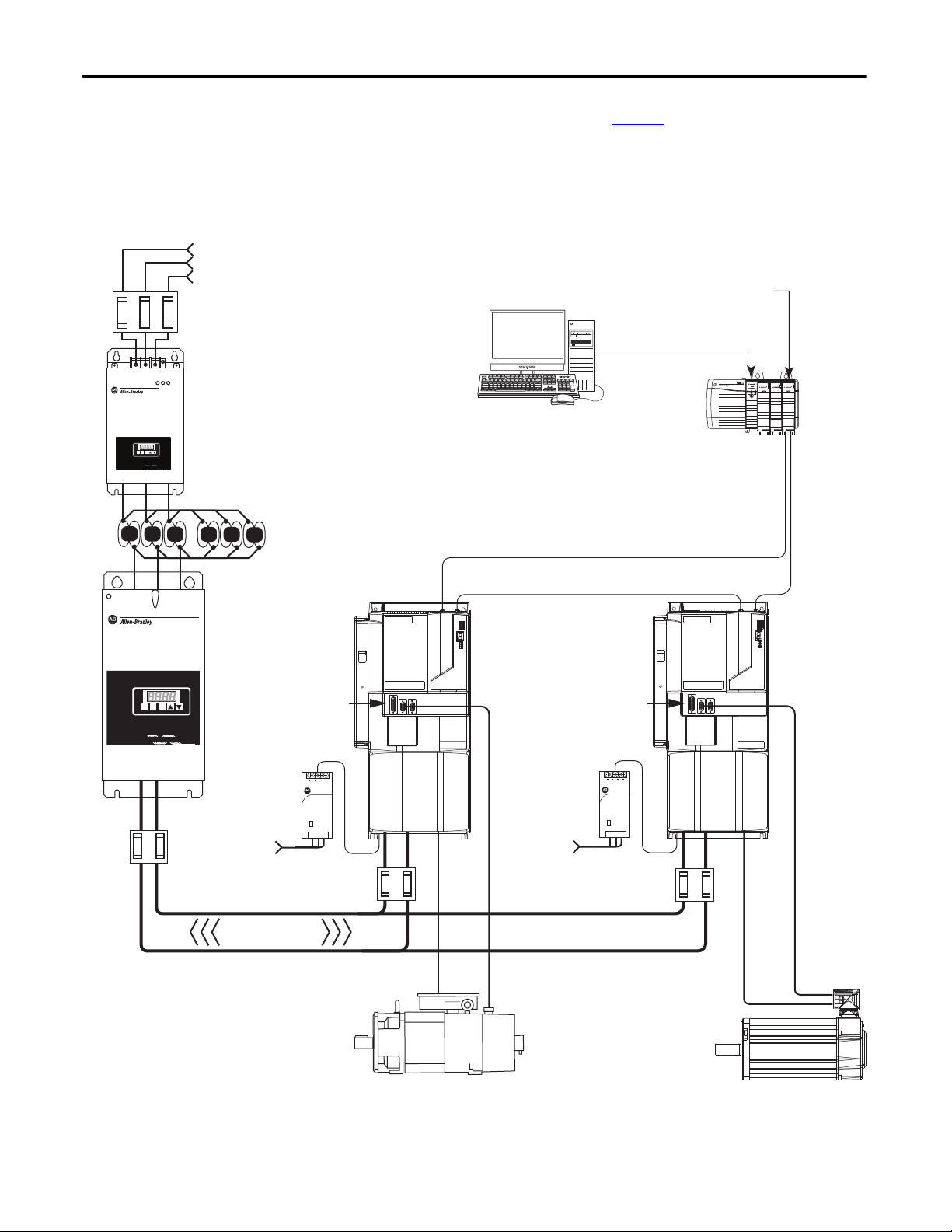
MAIN VACMAIN VAC
24V DC
Control Power
External Shunt Module (optional component). See
External Shunt Modules on page 156
for more
information.
2090-XXLF-TCxxxx
AC Line Fi lter
2094-BL75S
Line Interface Modul e
(optional component)
460V AC
Three- Phase
Input Power
RSLogix 5000 Software
Input
Logix 5000 Controller
Output
1756-MxxSE SERCOS
Interface Module
2090-SCxxx-x
SERCOS Fiber-Optic Ring
Commissioning
2099-BMxx-S Kinetix 7000 Drive
HPK-Series Motors, RDD-Series Direct Drive Motors, MPMB165xx and MPM-B215xx, and MPL-B5xxx, MPL-B6xxx,
MPL-B8xxx, and MPL-B9xxx (shown) Servo Motors
Control Logix Chass is
Motor Power Cable
Encoder
Feedback
Cable
2090-K6CK-Dxxx
Low Profile Connector Kits for
I/O, Motor Feedback,
and Auxiliary Feedback
Safe-off,
General Purpose I/O,
General Purpose Relay
Connections
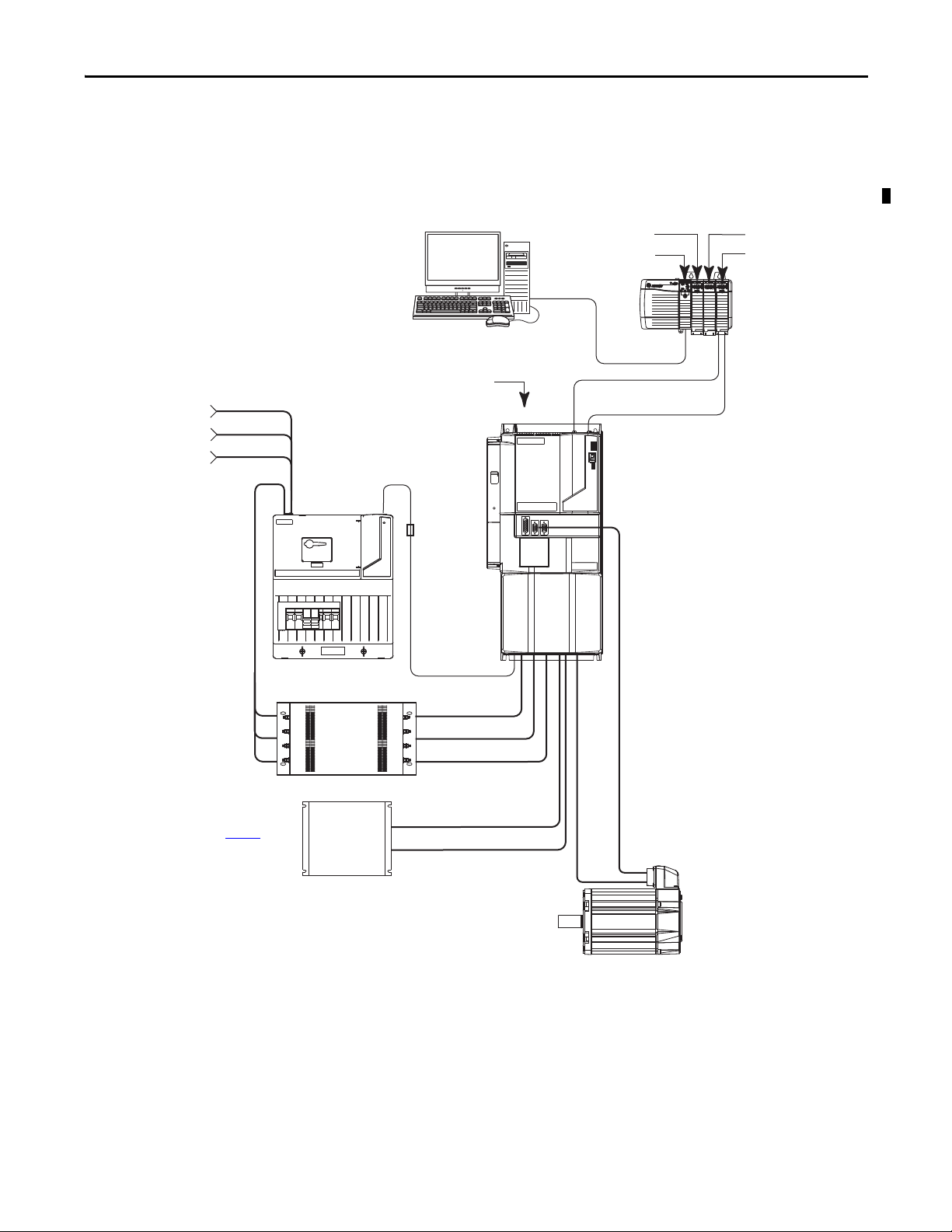
Typical Drive System Diagrams
Typical Kinetix 7000 system installations include three-phase AC configurations,
with and without the line interface module (LIM), and DC common bus
configurations.
Figure 1 - Kinetix 7000 System Configuration with LIM and External Resistive Shunt
Rockwell Automation Publication 2099-UM001D-EN-P - December 2012 13
Page 14
Chapter 1 Start
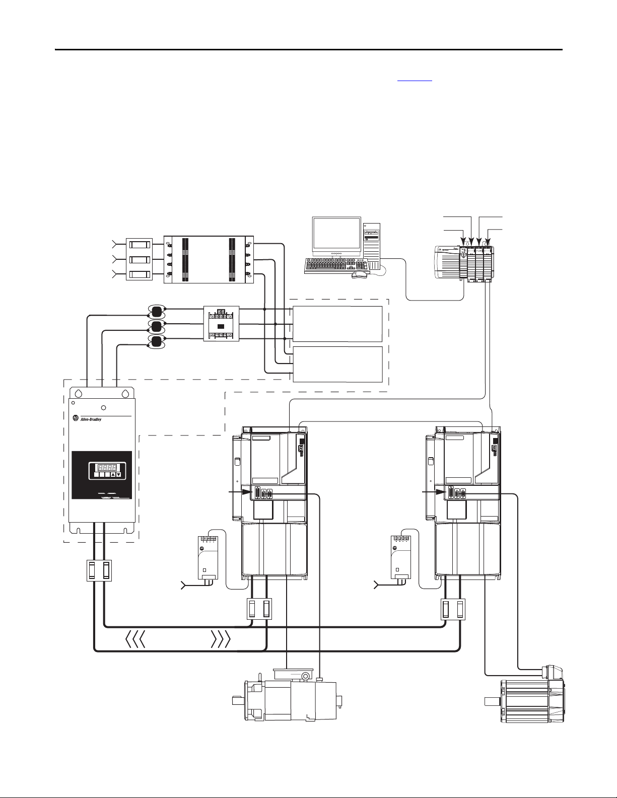
1606-XL
Power Supply
Input
Allen-Bradley
1606-XLxxx
24V DC
Control Power
2090-XXLF-TCxxxx
AC Lin e Filter
Input Fusing
Three- Phase
Input Power
Input
Logix 5000
Controlle r
Output
1756-MxxSE
SERCOS Interface Module
2090-SCxxx-x
SERCOS Fiber-Optic Ring
Commi ssionin g
2099-BMxx-S Kinetix 7000 Drive
ControlLog ix
Chassis
Motor Power Cable
Encoder
Feedback
Cable
2090-K6CK-Dxxx
Low Profile Connector Kits for
I/O, Motor Feedback,
and Auxiliary Feedback.
Contro l Power Sup ply
Input
Input
Contacto r
Safe-off,
General Purpose I/O,
General Purpose Relay
connections
External Shunt Module (optional component).
See External Shunt Modules on page 156
for more
information.
HPK-Series Motors, RDD-Series Direct Drive Motors, MPMB165xx and MPM-B215xx, and MPL-B5xxx, MPL-B6xxx,
MPL-B8xxx, and MPL-B9xxx (shown) Servo Moto rs
RSLogix 5000 Software
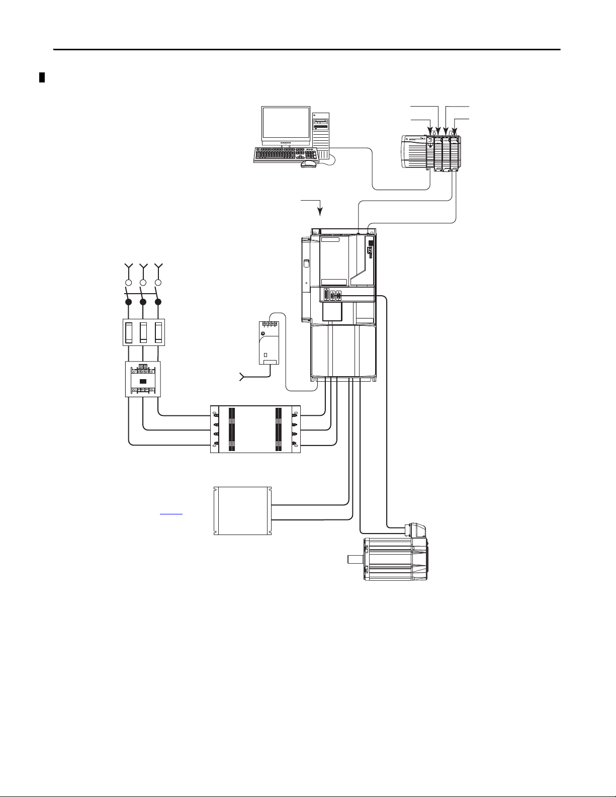
Figure 2 - Kinetix 7000 System Configuration without Line Interface Module (LIM)
14 Rockwell Automation Publication 2099-UM001D-EN-P - December 2012
Page 15
Start Chapter 1
REGENERA
TIVE POWER
SUPPLY
8720
MC
READY
FAULT
PROGRAM
kW
V
A
Encoder
Feedback
Cable
2090-SCxxx-x
SERCOS Fiber-optic Ring
DC Bus
8720MC-RPS065BM-HV2
Regenerative Power Supply
8720MC-LRxx
Line Reactor
Three-phas e
Input Power
8720MC-VA-B Varistor
Included with
8720MC-RPS065BM-HV2.
8720MC-HF-B2 Harmonic Filter
Included with
8720MC-RPS065BM-HV2.
Magnetic
Contacto r
Motor
Power
Cable
1606-XLxxx
24V DC
Contro l Power
8720MC-RFI80
AC Lin e Filter
(required for CE)
Input
Fusing
Three-phase
Input Power
Magnetic
Contacto r
Input
Fusing
1321-3R Typ e L ine Rea ct or,
3% compatible with
Kinetix 7000 Drive
Regenerative
Power O nly
2099-BMxx-S
Kinetix 7000 Drive
2090-K6CK-Dxxx
Low Profile Connector
Kits for I/O, Motor and
Auxiliary Feedback
Control Power
Supply Input
Logix SER COS
interface Module
ControlLogix Chassis
RSLogix 5000 Software
Logix Cont roller
Programming Network
Kinetix 7000 High Power
Servo Drive System
2090-XXLF-TCxxxx
AC Lin e Filter
(required for CE)
HPK-Series Motors, RDD-Series Direct
Drive Motors, MPM-B165xx and MPMB215xx, and MPL-B5xxx, MPL-B6xxx,
MPL-B8xxx, and MPL-B9xxx (shown)
Servo Motors
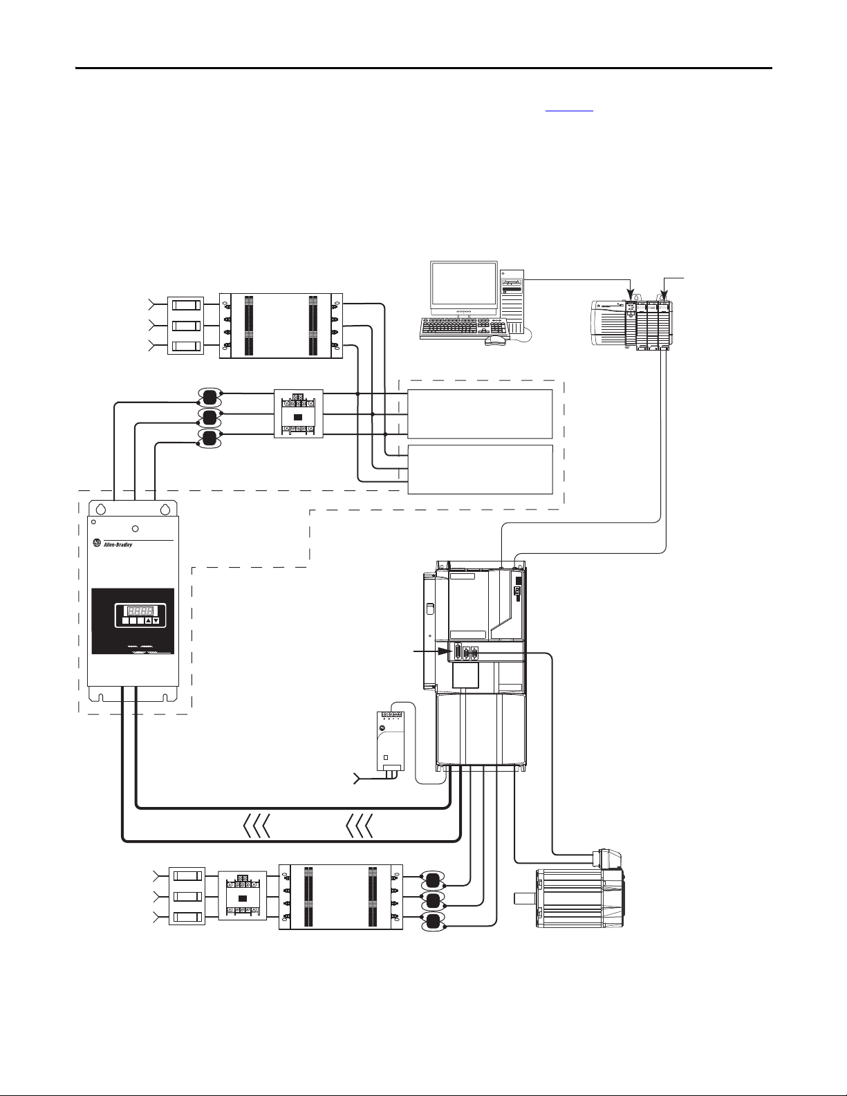
The Kinetix 7000 drive system shown in Figure 3 below illustrates a regenerative
power only configuration with a 8720MC regenerative power supply (RPS). The
harmonic filter and varistor are available separately, but are included with the
RPS unit when ordering the 8720MC-RPS065BM-HV2. In this configuration
the Kinetix 7000 drive provides motoring power and the 8720MC-RPS065
provides regenerative power.
Figure 3 - Kinetix 7000 System Configuration with AC Input and Regenerative Power Supply
READY
FAULT
PROGRAM
8720
ENT
PRG
RST
MC
RE G E N E R AT IV E P O W E R S U P P LY
kW
Allen-Bradley
1606-XL
Power Supply
Input
Rockwell Automation Publication 2099-UM001D-EN-P - December 2012 15
Page 16
1606-XL
Power Supply
Input
Allen-Bradley
R
EGE
NER
ATIVE PO
WER SUPPLY
REGENERATIVE PO
WER SUPPLY
87208720
MCMC
RST
PRG
ENT
READYREADY
FAULTFAULT
PROGRAMPROGRAM kWkW
V
A
1606-XL
Power Supply
Input
Allen-Bradley
R
EGENE
RA
TIVE
POW
ER
SU
PPLY
87208720
MCMC
RST
PRG
ENT
READYREADY
FAULFAULT
PR
OGRAMPROGRAM kWkW
V
A
2090-SCxxx-x
SERCOS Fiber-optic Ring
DC Bus
Kinetix 7000 Drive
2099-BM11-S
2090-K6CK-Dxxx
Low Profile Connector
Kits for I/O, Motor and
Auxiliary Feedback
8720MC-RPS190BM
Regenerative Power Supply
Three-p hase
Input Power
8720MC-EF190-VB
EMC Line Filter
This unit includes an AC line filter (required for CE), magnetic
contactor, harmonic filter, and varistor.
IMPORTANT The 8720MC-EF190-VB line filter unit and two
8720MC-LR10-100B line reactors are required when using the
8720MC-RPS190 regenerative power supply.
Input
Fusing
Full Regenerative
2099-BM11-S
Kinetix 7000 Drive
2090-K6CK-Dxxx
Low Profile Connector
Kits for I/O, Motor and
Auxiliary Feedback
1606-XLxxx
24V DC
Contro l Power
1606-XLxxx
24V DC
Control Power
Encoder
Feedback Cable
Motor
Power C able
HPK-Series Motors
DC Bus
Fusing
DC Bus
Fusing
Contro l Power
Supply Input
Control Power
Supply Input
Logix SERCOS
interface Module
RSLogix 5000 Software
Logix Controlle r
Programming Network
8720MC-LR10-100B
Line Reactor
(two units in parallel)
Encoder
Feedback
Cable
Motor
Power C able
HPK-Series Motors, RDD-Series Direct
Drive Motors, MPM-B165xx and MPMB215xx, and MPL-B5xxx, MPL-B6 xxx,
MPL-B8xxx, and MPL-B9xxx (shown)
Servo Motors
Ground
Faul t
Protection
Fusing
Chapter 1 Start
The Kinetix 7000 drive system shown in Figure 4 below illustrates a DC
common bus configuration with two follower Kinetix 7000 (2099-BM11-S)
drives and an 8720MC regenerative power supply (RPS). In full-line regenerative
mode the 8720MC-RPS190 unit provides motoring and regenerative power.
Figure 4 - Kinetix 7000 System Configuration with AC Input and 8720MC-RPS190 with Full-line
Regeneration
16 Rockwell Automation Publication 2099-UM001D-EN-P - December 2012
Page 17
Start Chapter 1
1606-XL
Power Supply
Input
Allen-Bradley
RE G E N E R AT IV E P O W ER
SU P
PLY
REGENERATIVE POWER SUPPLY
87208720
MCMC
RST
PRG
ENT
READYREADY
FAULTFAULT
PROGRAMPROGRAM kWkW
V
A
1606-XL
Power Supply
Input
Allen-Bradley
1606-XLxxx
24V DC
Control Power
8720MC-RF180
AC Line Fi lter
Input
Fusing
Three-P hase
Input Power
RSLogix 5000 Software
Input
Logix 5000
Control ler
Output
1756-MxxSE SERCOS
Interface Module
2090-SCxxx-x
SERCOS Fiber-Optic Ring
Commissioning
2099-BMxx-S
Kinetix 7000 Drive
Control Logix
Chassis
Motor Power Cable
Encoder
Feedback
Cable
2090-K6CK-Dxxx
Low Profile Connector Kits for
I/O, Motor Feedback,
and Auxiliary Feedback.
Control Power
Supply Input
(To retain l ogic control
when main DC power is
removed.)
Magnetic
Contacto r
1606-XLxxx
24V DC
Control Power
HPK-Series Motors
Motor Power Cable Encoder Feedback Cable
DC Bus
Fusing
DC Bus
Fusing
Full Reg enerative DC Bus
Control Power
Supply Input
(To retain logic
control when
main DC power
is removed.)
2099-BMxx-S
Kinetix 7000 Drive
2090-K6CK-Dxxx
Low Profile Connector Kits for
I/O, Motor Feedback,
and Auxiliary Feedback
Ground
Faul t
Protection
Fusing
8720MC-LRxx
Line Reactor
8720MC-RPS065BM-HV2
Regenerative Power Supply
Harmonic Filter
(included with
8720MC-RPS065BM-HV2
Regenerative Power Supply)
Vari sto r
(included with
8720MC-RPS065BM-HV2
Regenerative Power Supply)
HPK-Series Motors, RDD-Series Direct
Drive Motors, MPM-B165xx and MPMB215xx, and MPL-B5xxx, MPL-B6xxx,
MPL-B8xx
x, and MPL-B9xxx (shown)
Servo Motors
The Kinetix 7000 drive system shown in Figure 5 below illustrates a DC
common bus configuration with two follower Kinetix 7000 drives and an
8720MC regenerative power supply (RPS). The harmonic filter and varistor are
available separately, but are included when ordering the 8720MC-RPS065BMHV2 RPS unit. In full-line regenerative mode the 8720MC-RPS065BM-HV2
unit provides motoring power and regenerative power. In common bus mode,
you must calculate the total bus capacitance of your DC common bus system.
This allows you to plan your panel layout and sufficiently size the 8720MC-RPS
to precharge the entire system.
Figure 5 - Kinetix 7000 System Configuration with DC Input from 8720MC-RPS065 Providing Fullline Regeneration
Rockwell Automation Publication 2099-UM001D-EN-P - December 2012 17
Page 18
Chapter 1 Start
Catalog Number Explanation
Agency Compliance
Kinetix 7000 drive catalog numbers and descriptions are listed in the table below.
Kinetix 7000 Drive Cat. No.
Kinetix 7000, 460V, 22 kW, 40 A continuous output 2099-BM06-S
Kinetix 7000, 460V, 30 kW, 52 A continuous output 2099-BM07-S
Kinetix 7000, 460V, 37 kW, 65 A continuous output 2099-BM08-S
Kinetix 7000, 460V, 56 kW, 96 A continuous output 2099-BM09-S
Kinetix 7000, 460V, 75 kW, 125 A continuous output 2099-BM10-S
Kinetix 7000, 460V, 112 kW, 180 A continuous output 2099-BM11-S
Kinetix 7000, 460V, 149 kW, 248 A continuous output 2099-BM12-S
If this product is installed within the European Union or EEC regions and has
the CE mark, the following regulations apply.
ATT EN TI ON : Meeting CE requires a grounded system, and the method of
grounding the AC line filter and drive must match. Failure to do this renders the
filter ineffective and may cause damage to the filter.
For grounding examples, see Grounded Power Configurations
on page 75.
For more information on electrical noise reduction, see the System Design for
Control of Electrical Noise Reference Manual, publication GMC-RM001
.
18 Rockwell Automation Publication 2099-UM001D-EN-P - December 2012
Page 19

Start Chapter 1
CE Requirements - System without LIM
To meet CE requirements when your Kinetix 7000 system does not use a 2094
line interface module to supply AC line and dc control power, the following
requirements apply:
• Install an 8720MC-RF180 line filter as close to the 8720MC-RPS unit as
possible, and the AC line filter (2090-XXLF-TCxxxx) as close to the
Kinetix 7000 drive as possible.
• For MPx motors, use 2090 series motor power cables or use connector kits.
Terminate cable shields at the chassis and the motor terminal block with a
360° connection.
• For HPK-Series motors, use UL Approved 4 wire, 600V AC, shield, VFD
cabling. Terminate cable shields at the chassis and the motor with a 360°
connection.
• Combined motor power/feedback cables must not exceed 90 m (295.3 ft).
• Use 2090 series motor feedback cables or connector kits and terminate the
feedback shield as shown in Chapter 4 for wiring instructions and
Appendix B for motor feedback connector kit catalog numbers. Drive to
motor feedback cables must not exceed 90 m (295.3 ft).
• Install the Kinetix 7000 system inside an enclosure. Run input power
wiring in conduit (grounded to the enclosure) outside of the enclosure.
Separate signal and power cables.
• Output power, control (I/O), and signal wiring must be braided, shielded
cable with a coverage of 75% or better, metal conduit or equivalent
attenuation.
• All shielded cables should terminate with a properly shielded connector.
See the System Design for Control of Electrical Noise Reference Manual,
publication GMC-RM001
, for information on electrical noise reduction and
grounding practices.
Rockwell Automation Publication 2099-UM001D-EN-P - December 2012 19
Page 20

Chapter 1 Start
IMPORTANT
IMPORTANT
CE Requirements - System with LIM
To meet CE requirements when your Kinetix 7000 system includes the line
interface module (LIM), follow all the requirements as stated in CE
Requirements - System without LIM on page 19
requirements that also apply to the AC line filter:
• Install the LIM, 2094-XL75S-Cx or 2094-BL50/75S, and line filter
(2090-XXLF-TCxxx) as close to the Kinetix 7000 drive as possible.
The full rated current on the AC input line should not exceed that of the line
interface module.
Catalog numbers 2094-XL75S-Cx or 2094-BL50S for 2099-BM06-S and
2099-BM07-S Kinetix 7000 drives, or 2094-BL75S for 2099-BM08-S Kinetix
7000 drives.
CE requires use of a grounded secondary or source with a 2099-BMxx-S
drive.
Never use a LIM in an ungrounded input, due to the potential for high lineto-neutral voltages damaging components within the line filter.
and these additional
CE Requirements - System with DC Common Bus through 8720MC-RPS
To meet CE requirements when your Kinetix 7000 system includes a common
DC bus with an 8720MC-RPS, follow all the requirements as stated in the CE
Requirements - System without LIM on page 19
and wiring in the 8720MC Regenerative Power Supply Reference Manual,
publication 8720MC-RM001
• Install a three-phase line filter on the AC input power line of the RPS as
indicated in Interconnect Diagrams beginning on page 161
• Install a single-phase line filter when attaching an AC line input to the
RPS MC1/2 circuit as indicated in the Interconnect Diagrams beginning
on page 161
.
, and these additional requirements:
, the recommended installation
.
20 Rockwell Automation Publication 2099-UM001D-EN-P - December 2012
Page 21
Chapter 2
Install the Kinetix 7000 Drive System
This chapter describes system installation guidelines in preparation for mounting
your Kinetix 7000 drive components.
Top ic Pa ge
System Design Guidelines 22
Minimizing Electrical Noise 28
Mount the Kinetix 7000 Drive 39
ATT EN TI ON : Plan the installation of your system so that you can perform all
cutting, drilling, tapping, and welding with the system removed from the
enclosure. Because the system is of the open type construction, be careful to
keep any metal debris from falling into it. Metal debris or other foreign matter
can become lodged in the circuitry, which can result in damage to components.
Rockwell Automation Publication 2099-UM001D-EN-P - December 2012 21
Page 22

Chapter 2 Install the Kinetix 7000 Drive System
System Design Guidelines
To design your enclosure and plan where to mount the system components on the
panel, use this section and the information in the Kinetix Servo Drives
Specifications Technical Data, publication GMC-TD003
For online product selection and system configuration tools, including
AutoCAD (DXF) drawings of the product, go to:
http://www.rockwellautomation.com/en/e-tools/
.
.
System Mounting Requirements
Follow these system mounting requirements.
• To comply with UL and CE requirements, the Kinetix 7000 drive system
must be enclosed in a grounded conductive enclosure offering protection
as defined in standard EN 60529 (IEC 529) to NEMA/UL Type IP2X
such that they are not accessible to an operator or unskilled person. A
NEMA/UL Type 4X enclosure exceeds these requirements providing
protection to IP66.
• The panel you install inside the enclosure for mounting your system
components must be on a flat, rigid, vertical surface that won’t be subjected
to shock, vibration, moisture, oil mist, dust, or corrosive vapors (as
specified in Environmental Specifications on page 154
• Size the drive enclosure so as not to exceed the maximum ambient
temperature rating. Consider heat dissipation specifications for all drive
components.
• Segregate input power wiring and motor power cables from control wiring
and motor feedback cables. Use shielded cable for power wiring and
provide a grounded 360° clamp termination.
• Use high-frequency (HF) bonding techniques to connect the modules,
enclosure, machine frame, and motor housing, and to provide a lowimpedance return path for HF energy and reduce electrical noise.
).
See the System Design for Control of Electrical Noise Reference Manual,
publication GMC-RM001
reduction.
, to better understand the concept of electrical noise
Transformer Selection
The Kinetix 7000 drive does not require an isolation transformer for three-phase
input power. However, a transformer may be required to match the voltage
requirements of the controller to the available service.
22 Rockwell Automation Publication 2099-UM001D-EN-P - December 2012
Page 23

Install the Kinetix 7000 Drive System Chapter 2
IMPORTANT
IMPORTANT
To size a transformer for the AC power inputs to devices peripheral to the
Kinetix 7000 drive, refer to the manufacturer continuous output power
specification.
If using an autotransformer, make sure that the phase to neutral/ground
voltages do not exceed the input voltage ratings of the drive.
Use a form factor of 1.5 for three-phase power (where form factor is used to
compensate for transformer, drive module and motor losses, and to account
for utilization in the intermittent operating area of the torque speed curve).
For example: using a secondary of 480 VAC and a 2099-BM06-S with a rated
power output = 22 kW continuous:
22 * 1.5 = 33 kVA transformer
Circuit Breaker/Fuse Selection
The Kinetix 7000 drive uses internal solid-state motor short-circuit protection
and, when protected by suitable branch circuit protection, are rated for use on a
circuit capable of delivering up to 200,000 A. Fuses or circuit breakers, with
adequate withstand and interrupt ratings, as defined in NEC or applicable local
codes, are permitted.
The 2094-BL50 and 2094-BL75S LIMs contain supplementary protection
devices, but require a customer-supplied external line filter. See the Line Interface
Module Installation Instructions, publication 2094-IN005
, for power
specifications and more information on using the LIM module.
The Bulletin 140M motor protection circuit breakers are another acceptable
means of protection. As with fuses and circuit breakers, you must make sure that
the selected components are properly coordinated and meet applicable codes
including any requirements for branch circuit protection. When applying the
140M product, evaluation of the short circuit available current is critical and
must be kept below the short circuit rating of the 140M product.
In most cases, fuses selected to match the drive input current rating will meet the
NEC requirements and provide the full drive capabilities. Dual element, time
delay (slow acting) fuses should be used to avoid nuisance trips during the inrush
current of power initialization.
See Circuit Breaker/Fuse Specifications on page 151
for recommended circuit
breakers and fuses.
See Power Specifications on page 150
for input current and inrush current
specifications for your Kinetix 7000.
Rockwell Automation Publication 2099-UM001D-EN-P - December 2012 23
Page 24
Chapter 2 Install the Kinetix 7000 Drive System
Enclosure Selection
To assist you in sizing an enclosure, the following example is provided. The
example system consists of the following components.
• 2-axis Kinetix 7000 servo drive system
• ControlLogix chassis and modules
Size the Kinetix 7000 servo drive using Motion Analyzer software, version 4.2 or
later, and use the results to predict the amount of heat dissipated into the
enclosure. You will also need heat dissipation data from other equipment inside
the enclosure (such as ControlLogix). Once the total amount of heat dissipation
(in watts) is known, the minimum enclosure size can be calculated. It is
recommended that you also contact the enclosure manufacturer for the best
enclosure fit, including possible cooling methods to help reduce enclosure size.
Using Motion Analyzer to Determine Heat Dissipation
To obtain Motion Analyzer software, go to:
http://ab.rockwellautomation.com/Motion-Control/Motion-AnalyzerSoftware
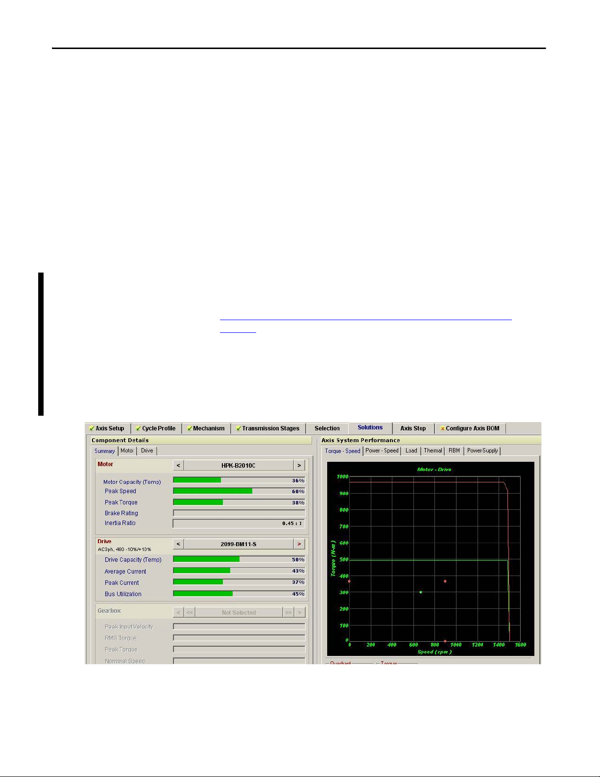
Complete the Motion Analyzer Axis View data to find an acceptable Kinetix
7000 drive and motor solution to meet the application needs. In the Axis View
Solutions window find the Drive Capacity value. In this example, the
2099-BM11-S Drive Capacity characteristic can be used for the estimation of the
Rated Power Output used for the percentage of watts dissipated.
24 Rockwell Automation Publication 2099-UM001D-EN-P - December 2012
Page 25
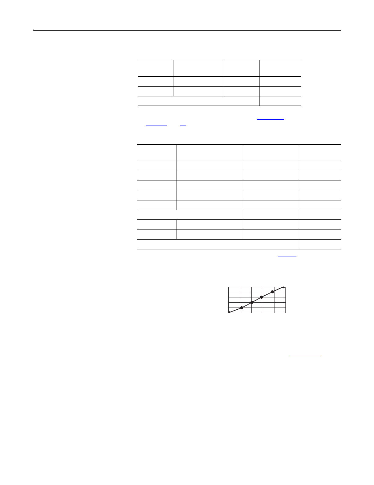
Table 2 - Kinetix 7000 System Heat Dissipation Example
75
60
45
30
15
0
0 20 40 60 80 100
Backplane
Power Load
(Watts)
Real Power (Watts)
1756-P B72
1756-P B75
DC
Install the Kinetix 7000 Drive System Chapter 2
Enclosure
Component
Description Loading
(Motion Analyzer)
(1)
Heat Dissipation
Watts
(2)
2099-BM08-S Kinetix 7000 Servo Drive 50% 452
2099-BM11-S Kinetix 7000 Servo Drive 50% 1275
Total Wattage of Kinetix 7000 system 1727
(1) Loading determined using Motion Analyzer software.
(2) To determine heat dissipation specifications for the Kinetix 7000 drive, see Power Dissipation
Specifications on page 152.
Table 3 - ControlLogix Heat Dissipation Example
Enclosure
Component
Description Backplane Power Load
Watts
1756-M08SE 8-axis SERCOS interface module 3.2 0.0
1756-L5563 L63 ControlLogix processor 4.5 0.0
1756-IB16D 16-point input module 0.84 5.8
1756-OB16D 16-point output module 4.64 3.3
1756-ENxTx EtherNet/IP communication module 4.0 0.0
Backplane total 17.18
(2)
1756-PB72 24V DC ControlLogix power supply N/A 25.0
1756-A7 7-slot mounting chassis N/A N/A
Total ControlLogix system wattage 34.1
(1)
Heat Dissipation
Watts
(1)
N/A
(2)
(1) For ControlLogix module specifications, see the ControlLogix Selection Guide, publication 1756-SG001.
(2) Real power heat dissipation is determined by applying the backplane power load (17.18 W) to the graph below.
Figure 6 - ControlLogix Real Power
For backplane power loading requirements of other ControlLogix power
supplies, see the ControlLogix Selection Guide, publication 1756-SG001
.
Rockwell Automation Publication 2099-UM001D-EN-P - December 2012 25
Page 26
Chapter 2 Install the Kinetix 7000 Drive System
A
0.38Q
1.8T 1.1–
--------------------------=
A
4.08Q
T 1.1–
------------------=
A =
0.38 (1761)
1.8 (20) - 1.1
A =
19.2 m
2
In this example, the amount of power dissipated inside the cabinet is the sum of
the Kinetix 7000 drive (2099-BM08-S and 2099-BM11-S) system value (1727
W) and the ControlLogix value (34.1 W) for a total of 1761 W.
With no active method of heat dissipation (such as fans or air conditioning)
either of the following approximate equations can be used.
Metric Standard English
Where T is temperature difference between inside air and
outside ambient (°C), Q is heat generated in enclosure
(Watts), and A is enclosure surface area (m2). The exterior
surface of all six sides of an enclosure is calculated as
A = 2dw + 2dh + 2wh A = (2dw + 2dh + 2wh) / 144
Where d (depth), w (width), and h (height) are in meters. Where d (depth), w (width), and h (height) are in inches.
Where T is temperature difference between inside air and
outside ambient (°F), Q is heat generated in enclosure
(Watts), and A is enclosure surface area (ft²). The exterior
surface of all six sides of an enclosure is calculated as
The maximum ambient rating of the Kinetix 7000 drive is 50 °C (122 °F) and if
the maximum environmental temperature is 30 °C (86 °F) then Q=1761 and
T=20 in the equation below.
2
In this example, the enclosure must have an exterior surface of 19.2 m
. If any
portion of the enclosure is not able to transfer heat, it should not be included in
the calculation. For instance, if an externally-mounted shunt system is used with
the Kinetix 7000 system, it should not be included in the equation.
The minimum enclosure size must take into account the physical size and
minimum clearance requirements of the two Kinetix 7000 drives and the
additional ControlLogix and other devices required to meet the application
needs.
If the enclosure size is considerably larger than what is necessary to house the
system components, it may be more efficient to provide a means of cooling in a
smaller enclosure. Contact your enclosure manufacturer for options available to
cool your enclosure.
26 Rockwell Automation Publication 2099-UM001D-EN-P - December 2012
Page 27
Install the Kinetix 7000 Drive System Chapter 2
IMPORTANT
50.8 mm (2.0 in.) clearance right
of module is required
Minimum cabinet depth = 300 mm (11.8 in.)
Cable bend radius requires a minimum of
60 mm (2.4 in.) from the front panel connections.
101.6 mm (4.0 in.) clearance for
airflow and installation
50.8 mm (2.0 in.) clearance left
of module is required
101.6 mm (4.0 in.) clearance for
airflow and installation
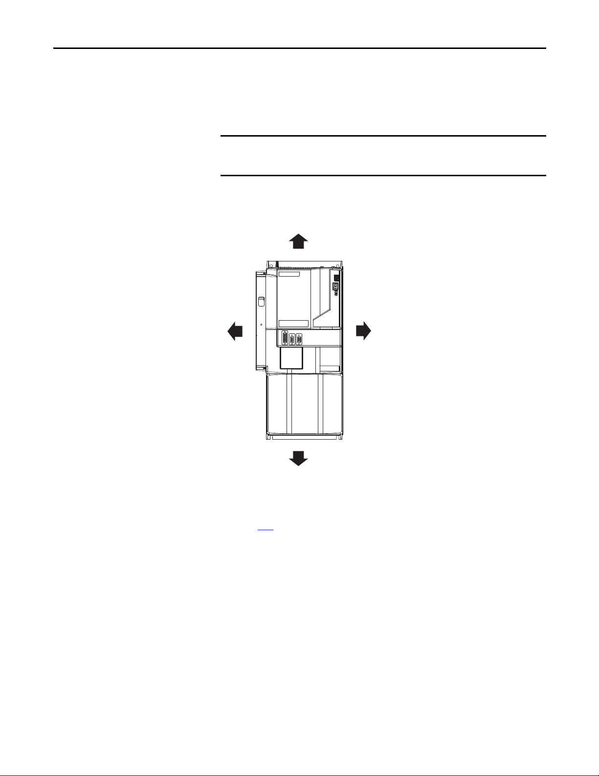
Minimum Clearance Requirements
This section provides information to assist you in sizing your cabinet and
positioning your Kinetix 7000 system components.
Mount the module in an upright position as shown. Do not mount the
module on its side.
Figure 7 - Minimum Clearance Requirements
See page 152 for power dissipation specifications.
Rockwell Automation Publication 2099-UM001D-EN-P - December 2012 27
Page 28

Chapter 2 Install the Kinetix 7000 Drive System
IMPORTANT
Minimizing Electrical Noise
This section outlines best practices that minimize the possibility of noise-related
failures as they apply specifically to Kinetix 7000 drive installations. For more
information on the concept of high-frequency (HF) bonding, the ground plane
principle, and electrical noise reduction, see the System Design for Control of
Electrical Noise Reference Manual, publication GMC-RM001
.
Bonding Modules
Bonding is the practice of connecting metal chassis, assemblies, frames, shields,
and enclosures to reduce the effects of electromagnetic interference (EMI).
Unless specified, most paints are not conductive and act as insulators. To achieve
a good bond between the drive and subpanel, surfaces need to be unpainted or
plated. Bonding metal surfaces creates a low-impedance return path for highfrequency energ y.
To improve the bond between the drive and subpanel, construct your
subpanel out of zinc plated (unpainted) steel.
Improper bonding blocks the direct return path and routes high-frequency
energy to elsewhere in the cabinet. Excessive high-frequency energ y can effect the
operation of other microprocessor controlled equipment.
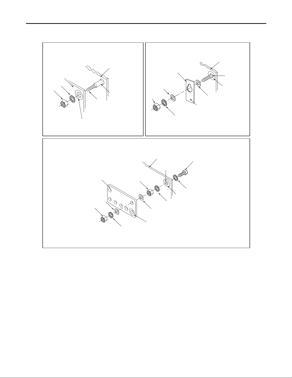
The illustrations that follow show details of recommended bonding practices for
painted panels, enclosures, and mounting brackets.
28 Rockwell Automation Publication 2099-UM001D-EN-P - December 2012
Page 29
Install the Kinetix 7000 Drive System Chapter 2
Stud-mounting the Subpanel
to the Enclosure Back Wall
Stud-mounting a Ground Bus
or Chassis to the Subpanel
Subpanel
Weld ed St ud
Scrape Paint
Flat Washer
If the mounting bracket is coated with
a non-conductive material (anodized,
painted, etc.), scrape the material
around the mounting hole.
Star Washer
Nut
Nut
Flat Washer
Mounting Bracket or
Ground Bus
Use a wire brush to rem ove paint from
threads to maximize ground connection.
Back Wall of
Enclosure
Welded Stu d
Subpanel
Star Washer
Use plated panels or scrape paint off
front of panel.
Subpanel
Nut
Nut
Star Washer
Flat Washer
Star
Was her
Star Washer
Scrape paint on both sides of panel
and use star washers.
Tap pe d
Hole
Bolt
Flat Washer
Ground Bus or
Mounting Bracket
If the mounting bracket is coated with a non-co nductive
material (anodized, or painted for example), scrape the
material around the mounting hole.
Bolt-mounting a Ground Bus or Chassis to the Back-panel
Figure 8 - Recommended Bonding Practices for Painted Panels
Rockwell Automation Publication 2099-UM001D-EN-P - December 2012 29
Page 30
Chapter 2 Install the Kinetix 7000 Drive System
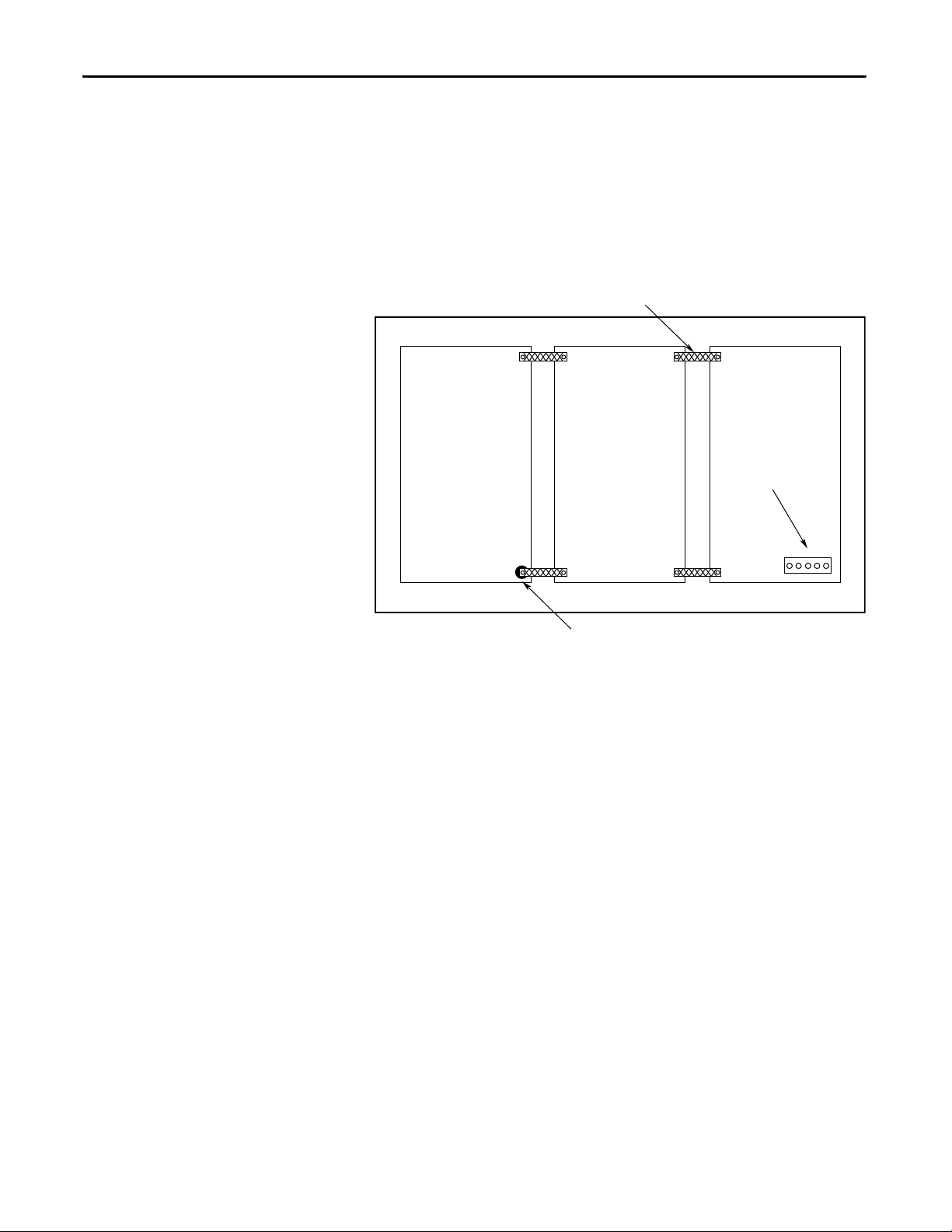
Bond the top and bottom of each subpanel to the cabinet using 25.4
mm (1.0 in.) by 6.35 mm (0.25 in.) wire braid.
Scrape the paint around each fastener to
maximize metal to metal contact.
Cabinet ground bus bonded
to the subpanel.
Bonding Multiple Subpanels
Bonding multiple subpanels creates a common low impedance exit path for the
high frequency energy inside the cabinet. Subpanels that are not bonded together
may not share a common low impedance path. This difference in impedance may
affect networks and other devices that span multiple panels.
Figure 9 - Multiple Subpanels and Cabinet Recommendations
Establish Noise Zones
When designing a panel for a Kinetix 7000 system, observe the following
guidelines with additional attention to zone locations.
30 Rockwell Automation Publication 2099-UM001D-EN-P - December 2012
Page 31

Install the Kinetix 7000 Drive System Chapter 2
REGENERATIVE POWER SUPPLY
8720
MC
READY
FAULT
PROGRAM
kW
V
A
Route Encoder/Analog/Registration
Shielded Cable
Shielded Cable or
Conduit
Clean Wireway (Cx)
No sensitive
equipment within
150 mm (6.0 in.)
Dirty Wireway (Dx)
Shield Clamps
(beneath cover)
Motor Power
Shielded Cable
8720MC
Line Reactor
Registration I/O
24V DC
Kinetix 7000 Drive
24V DC I/O
Shielded Cable
GPIO, GPR, and SO Cables Dirty Wireway (Dx)
24V DC
Power
Supply
DC Bus ≤2 m (78.7 in.)
Keep very dirty ( VD) connections as short as
possible and segregated (not in wireway)
AC
Line
Filter
Magnetic
Contac tor
Line
Fuses
Circuit
Breaker
8720MC-RPS065BM-HV2
Regenerative Power Supply
Harmonic
Filter
Vari sto r
Encoder Feedback
Noise Zones when Using Regenerative Power Supplies (with/without a Line Filter Unit)
Observe the following guidelines when laying out a Kinetix 7000 system panel if
a regenerative power supply (8720-RPSxxxxx) is used (see Figure 10
regenerative power supply and line filter unit are used (see Figure 11
• Mount the regenerative power supply to the right of the drive.
• The clean zone (C) is beneath and left of the Kinetix 7000 drive. This zone
includes the motor feedback, auxiliary feedback and registration signals
from the IOD connector (grey wireway).
• The dirty zone (D) is to the right of the Kinetix 7000 drive. This zone
includes the motor power, GPIO, GPR, SO, and IOD connections (black
wireway).
• The very dirty zone (VD) includes both the 8720MC-RPS DC output to
the Kinetix 7000 drive and the fuses, contactors, circuit breakers, and AC
line input to the EMC line filter to the right of the 8720MC-RPS.
Shielded cable is required only if the very dirty cables enter a wireway.
• The SERCOS fiber-optic cables are immune to electrical noise.
Figure 10 - Establishing Noise Zones (Regenerative Power Supply)
), and if a
on page 32).
C1
C1
D3
READY
FAULT
PROGRAM
MC
8720
kW
ENT
PRG
RST
RE
GE N E R
AT IV
E P
PLY
OW E
R S U
P
VD
VD
D2
D1
D2
Rockwell Automation Publication 2099-UM001D-EN-P - December 2012 31
Page 32

Chapter 2 Install the Kinetix 7000 Drive System
REGENERATIVE POWER SUPPLY
8720
MC
READY
FAULT
PROGRAM
kW
V
A
8720
MC
READY
FAULT
PROGRAMkWkW
V
A
Route Encoder/Analog/Registration
Shielded Cable
Shielded Cable or
Conduit
Clean Wireway (Cx)
No sensitive
equipment within
150 mm (6.0 in.)
Dirty Wireway (Dx)
Shield Clamps
(beneath cover)
Motor Power
Shielded Cable
Line
Reactor
Registration I/O
24V DC
Kinetix 7000 Drive
24V DC I/O
Shielded Cable
GPIO, GPR, and SO Cables Dirty Wireway (Dx)
24V DC
Power
Supply
Keep very dirty connections as short as
possible and segregated (not in wireway)
Line
Fuses
Circuit
Breaker
8720MC-RPS190BM-HV2
Regenerative Power Supply
Encoder Feedback
DC Bus ≤2 m (78.7 in.)
Line
Reactor
8720MC -LR10-100B
Line Reactors
8720MC-EF190-VB
EMC Line Filter
1.5 m
(5 ft)
Figure 11 - Establishing Noise Zones (Regenerative Power Supply with Line Filter Unit)
C1
C1
D3
VD
READY
FAULT
8720
PROGRAM
MC
PRG
RST
RE
GE N E R AT IV E P
kW
ENT
OW E
R S U
PP LY
READY
FAUL
PROGRAM
ENT
PRG
RST
8720
MC
LY
E
NE
POWER SUPP
RATIV
REGE
VD
VD
VD
D2
D1
VD
D2
32 Rockwell Automation Publication 2099-UM001D-EN-P - December 2012
Page 33

Install the Kinetix 7000 Drive System Chapter 2
Route Encoder/Analog/Registration
Shielded Cable
Shielded Cable or
Condu it
Clean Wireway (C)
No sensitive
equipment within 150
mm (6.0 in.)
(1)
Shield Clamps
(beneath cover)
Motor Power
Shielded Cable
Kinetix 7000 Drive
24V DC I/O Shielded
Cable
Dirty Wireway (D)
Keep very dirty connections as short as
possible and segregated (not in wireway)
AC Lin e
Filter
Contac tor
Line
Fuses
Circuit
Breaker
Shielded Clamps
AC Power Noise Zones
Observe the following guidelines when laying out a Kinetix 7000 system panel, if
an AC power supply is used (and regenerative power will not be used).
• The clean zone (C) is beneath and left of the Kinetix 7000 drive. This zone
includes the motor feedback, auxiliary feedback and registration signals
from the IOD connector (grey wireway).
• One dirty zone (D) is beneath and right of the Kinetix 7000 drive. This
zone includes fuses, contactors, circuit breakers, AC line input to the
EMC line filter (black wireway).
• The very dirty zone (VD) is limited to where the AC line output exits
from the EMC line filter and connects to the Kinetix 7000 drive. Shielded
cable is required only if the very dirty cables enter a wireway.
• The SERCOS fiber-optic cables are immune to electrical noise.
Figure 12 - Establishing Noise Zones (AC Power)
C
VD
C
(1)
When space does not permit the 150 mm (6.0 in.) segregation, use a grounded steel shield instead. For examples, see the System
Design for Control of electrical Noise Reference Manual, publication GMC-RM001
D
D
.
Rockwell Automation Publication 2099-UM001D-EN-P - December 2012 33
Page 34

Chapter 2 Install the Kinetix 7000 Drive System
AC Line
Filter
Spare Slot(s)
Dirty Wireway (D)
Clean Wireway (C)
Route dirty wireways directly above the ControlLogix rack
(shielded by the chassis).
Line Filter/Power Supply
Connections Segregated
(not in wireway)
Dirty I/O
(24V DC I/O, AC I/O)
Clean I/O
(Analog, Encode r
Registration)
1756-MxxSE SERCOS Interface Module Noise Zones
Observe the following guidelines when installing your 1756-MxxSE SERCOS
interface module.
• The clean zone (C) is beneath the less noisy I/O modules (analog,
encoder, registration) - - (grey wireway).
• The dirty zone (D) is above and below the power supply and noisy
modules (black wireway).
• The SERCOS fiber-optic cables are immune to electrical noise.
Figure 13 - Establishing Noise Zones (ControlLogix)
D
D
C
34 Rockwell Automation Publication 2099-UM001D-EN-P - December 2012
Page 35

Install the Kinetix 7000 Drive System Chapter 2
Cable Categories for Kinetix 7000 Systems
The table below indicates the zoning requirements of input power cables
connecting to the Kinetix 7000 drive.
Table 4 - Kinetix 7000 Drive
Wire/Cable Connector Zone Method
Very
Dirty
Control Power CP X
DC-/DC+
L1, L2, L3 (shielded cable) X X
L1, L2, L3 (unshielded cable) X
DPI DPI X X
PTB
The table below indicates the zoning requirements of power and control cables
connecting to the Kinetix 7000 system.
Dirty Clean Ferrite
X
Sleeve
Shielded
Cable
Table 5 - Kinetix 7000 System
Wire/Cable Connector Zone Method
Very
Dirty
U, V, W ( Motor Power) MP X X
GPR+, GPR- (Motor Brake) GPR X
24V DC (PWR), COM, filtered
24V DC (PWR), COM, unfiltered X
24V DC (PWR), COM, safety enable,
and feedback signals for safe-off
feature
Motor Feedback MF X X
Auxiliary Feedback AF X X
Registration and Analog Outputs
Others X
Fiber-optic Rx and Tx No Restrictions
GPIO, GPR
SO X
IOD
Dirty Clean Ferrite
Sleeve
X
XX
Shielded
Cable
Rockwell Automation Publication 2099-UM001D-EN-P - December 2012 35
Page 36

Chapter 2 Install the Kinetix 7000 Drive System
IMPORTANT
Table 6 - Line Interface Module
Wire/Cable Connector Zone Method
Very
Dirty
VAC line (main input) IPL X
230V AC input APL X
VAC load (shielded option)
VAC load (unshielded option) X
Control power output CPL X
MBRK PWR, MBRK COM P1L/PSL X
Status I/O IOL X
Auxiliary 230V AC P2L X
OPL
Dirty Clean Ferrite
Sleeve
XX
Table 7 - External Shunt Resistor Kit
Wire/Cable Connector Zone Method
Very
Dirty
COL, DC+ (shielded option)
COL, DC+ (unshielded option) X
Thermal switch TS X X
Fan ( if pr esent ) N /A X
RC
Dirty Clean Ferrite
Sleeve
XX
Shielded
Cable
Shielde
d Cable
Noise Reduction Guidelines for Drive Accessories
When mounting an AC (EMC) line filter or external shunt resistor refer to the
sections below for guidelines designed to reduce system failures caused by
excessive electrical noise.
AC Line Filters
Observe the following guidelines when mounting your AC (EMC) line filter.
See the Establishing Noise Zones (AC Power)
• Mount the ac line filter on the same panel as the Kinetix 7000 drive and as
close to the power input as possible.
• Good HF bonding to the panel is critical.
For painted panels, refer to the examples on page 29.
• Segregate input and output wiring as far as possible.
CE test certification applies only to ac line filter and single drive. Sharing a
line filter with multiple drives may perform satisfactorily, but the user takes
legal responsibility.
on page 33 for an example.
36 Rockwell Automation Publication 2099-UM001D-EN-P - December 2012
Page 37

Install the Kinetix 7000 Drive System Chapter 2
Kinetix 7000 drive
Clean Wireway Dirty Wireway
No sensitive
equipment within
150 mm (6.0 in.)
Motor Power Cables
Very dirty connections segregated (not
in wireway)
Route 24V DC I/O
Shielded Cable
Route Encoder/Analog/
Registration
Shielded Cables
Customer-supplied
metal enclosure
Minimum of 150 mm (6.0 in.) of clearance
on all sides of the shunt module
Enclosure
Shunt Power Wiring Methods:
Twisted pair in conduit (1st choice)
Shielded twisted pair (2nd choice)
Twisted pair, 2 twists per foot min. (3rd choice)
Metal conduit
(where required
by local code)
I/O and Feedback
Cables
Shunt Resistor
Observe the following guidelines when mounting your external shunt resistor
outside the enclosure.
• Mount circuit components and wiring in the very dirty zone or in an
external shielded enclosure. Run shunt power and fan wiring inside metal
conduit to minimize the effects of EMI and RFI.
• Mount resistors (other than metal-clad) in a shielded and ventilated
enclosure outside the cabinet
• Keep unshielded wiring as short as possible. Keep shunt wiring as flat to
the cabinet as possible.
• Route thermal switch and fan wires separate from shunt power.
Figure 14 - External Shunt Resistor Outside the Enclosure
C1
VD
D3
VD
VD
D1
D1
D2
C1
Rockwell Automation Publication 2099-UM001D-EN-P - December 2012 37
D2
Page 38

Chapter 2 Install the Kinetix 7000 Drive System
Kinetix 7000
Dirty WirewayClean Wireway
No sensitive
equipment within
150 mm (6.0 in.)
Motor Power Cables
Very dirty connections segregated (not
in wireway)
Route 24V DC I/O
Shielded Cable
Route Encoder/Analog/Registration
Shielded Cables
Observe minimum clearance
requirements for shunt
module spacing.
Enclosure
Shunt Module
Shunt Wiring Methods:
Twisted pair in conduit (1st choice).
Shielded twisted pair (2nd choice).
Twisted pair, 2 twists per foot min.
(3rd choice).
I/O and Feedback
Cables
AC Line
Filter
When mounting your shunt module inside the enclosure, follow these additional
guidelines.
• Metal-clad modules can be mounted anywhere in the dirty zone, but as
close to the Kinetix 7000 system as possible.
• Shunt power wires can be run with motor power cables.
• Keep unshielded wiring as short as possible. Keep shunt wiring as flat to
the cabinet as possible.
• Separate shunt power cables from other sensitive, low voltage signal cables.
• The shunt module watts dissipation must be included in the Kinetix 7000
system heat dissipation calculation for selecting an enclosure.
Figure 15 - External Shunt Resistor Inside the Enclosure
C1
D3
VD
VD
VD
D2
C1
D2
D1
D1
Motor Brake and Thermal Switch
The thermal switch and brake are mounted inside the motor, but how you
connect to the axis module depends on the motor series.
See Wire Motor Output Power on page 92
38 Rockwell Automation Publication 2099-UM001D-EN-P - December 2012
drive/motor combination, and to Interconnect Diagram Notes
the interconnect diagram of your drive/motor combination.
for wiring guidelines specific to your
on page 162 for
Page 39

Mount the Kinetix 7000 Drive
Install the Kinetix 7000 Drive System Chapter 2
SHOCK HAZARD: To avoid hazard of electrical shock, perform all mounting and
wiring of the drive prior to applying power. Once power is applied, connector
terminals may have voltage present even when not in use.
ATT EN TI ON : Plan the installation of your system so that you can perform all
cutting, drilling, tapping, and welding with the system removed from the
enclosure. Because the system is of the open type construction, be careful to
keep any metal debris from falling into it. Metal debris or other foreign matter
can become lodged in the circuitry, which can result in damage to components.
Follow these steps to install your Kinetix 7000 drive.
1. Layout and mark the position for your drive in the enclosure.
Follow the Kinetix 7000 mounting information provided in Figure 16 on
page 40. Clearance requirements on page 27 must also be followed.
2. Attach the drive to the cabinet.
The recommended mounting bolts are listed in the table on page 40
Follow the recommended high-frequency (HF) bonding techniques as
shown in Bonding Modules
Follow the lifting instructions found in the Kinetix 7000 High Power
Servo Drive Installation Instructions, publication 2099-IN003
3. Tighten all mounting fasteners.
beginning on page 28.
.
.
Rockwell Automation Publication 2099-UM001D-EN-P - December 2012 39
Page 40

Chapter 2 Install the Kinetix 7000 Drive System
B
C
M1
M2 M3
A
2099-BM07 shown
IMPORTANT
Figure 16 - Kinetix 7000 Approximate Mounting Dimensions
Kinetix 7000 Drive
Cat. No.
2099-BM06-S
2099-BM07-S
2099-BM08-S
2099-BM09-S 644.5 (25.37) 331.9 (13.07) 286.7 (11.29) 625.0 (24.61) 225.0 (8.86) 37.5 (1.48) M6 (0.25)
2099-BM10-S 690.3 (38.47) 331.9 (13.07) 286.7 (11.29) 625.0 (24.61) 225.0 (8.86) 37.5 (1.48) M6 (0.25)
2099-BM11-S
2099-BM12-S
Dimensions in mm (in.)
Mounting Screw SizeA B C M1M2M3
517.5 (20.37) 254.12 (10.0) 224.3 (8.83) 495.0 (19.49) 192.0 (7.56) 15.3 (0.60) M6 (0.25)
977.1 (38.47) 429.2 (16.90) 282.7 (11.13) 824.0 (32.44) 300.0 (11.81) 49.6 (1.95) M8 (0.3125)
Each Kinetix 7000 drive requires four mounting screws.
40 Rockwell Automation Publication 2099-UM001D-EN-P - December 2012
Page 41

Chapter 3
Kinetix 7000 Connector Data
This chapter provides power, feedback, and I/O connector locations and signal
descriptions for a Kinetix 7000 drive.
Top ic Pa ge
Locate and Identify Connectors and Indicators 42
Control Signal Specifications 54
Control Power Specifications 65
Motor (MF) and Auxiliary Feedback (AF) Connections 66
Rockwell Automation Publication 2099-UM001D-EN-P - December 2012 41
Page 42

Chapter 3 Kinetix 7000 Connector Data
Status
Auxiliary
Feedback
Motor
Feedback
I/O
Fault/Status
SERCOS
CP_24VDC
CP_COM
CP
Node Address
Drive
Comm
Bus
Status
Fault/Status
SERCOS
Node Address
Drive
Comm
Bus
Auxiliary
Feedback
Motor
Feedback
I/O
Power terminal block located
behind protective cover.
2099-BM08-S shown
1
2
3
6
7
8
9
4
5
10
Locate and Identify Connectors and Indicators
Although the physical size of the drives vary, the location of the connectors and
indicators is identical.
Figure 17 - Kinetix 7000 Front Panel Connectors and Displays
Item Designator/Label Description Connector See Page
1 Node Address SERCOS Node Address Switches – Chapter 6
2 Fault/Status Fault Status Display – Chapter 7
3 Drive Drive Status LED – Chapter 7
4 Comm Communication Status LED – Chapter 7
5Bus Bus Status LED – Chapter 7
6 AF Auxiliary Feedback Connector 15-pin high-density D-shell (male) 49
7 MF Motor Feedback Connector 15-pin high-densit y D-shell (female) 47
8 IOD Digital and Analog Input/Output Connector 26-pin high-density D-shell 45
9– Control Power Status LED – Chapter 7
10 PTB Power Terminal Block Terminal block 51
42 Rockwell Automation Publication 2099-UM001D-EN-P - December 2012
Page 43

Figure 18 - Kinetix 7000 Top Panel Connectors and Switches
DO1
DO1_24VDC
DO2
DO2_24VDC
N/C
N/C
REGEN_OK+
REGEN_OK-
GPIO
GPR2-
COM
GPR2+
GPR1-
GPR1+
24VDC
GPR
FDBK2+
FDBK2-
FDBK1+
FDBK1-
ENABLE2+
ENABLE-
ENABLE1+
SO_24VDC
SO_COM
SO
DO1
DO1_24VDC
DO2
DO2_24VDC
N/C
N/C
REGEN_OK+
REGEN_OK-
GPIO
GPR2-
COM
GPR2+
GPR1-
GPR1+
24VDC
GPR
FDBK2+
FDBK2-
FDBK1+
FDBK1-
ENABLE2+
ENABLE-
ENABLE1+
SO_24VDC
SO_COM
SO
2099-BM08-S shown
1
Top Vie w
2 3 4 5 6 7
Kinetix 7000 Connector Data Chapter 3
Item Designator/Label Description Connector See Page
1 SO Safe-off Terminal Block 9-position plug/header 50
2 GPIO General Purpose I/O Terminal Block 8-position plug/header 63
3 GPR General Purpose Relay Terminal Block 6-position plug/header 64
4 Rx SERCOS Fiber-optic Receive Port SERCOS fiber-optic 65
5 DPI Device Peripheral Interface Connector – –
6Tx SERCOS Fiber-optic Transmit Port SERCOS fiber-optic 65
7 Baud Rate SERCOS Baud Rate and Optical Power Switches – 65
Rockwell Automation Publication 2099-UM001D-EN-P - December 2012 43
Page 44

Chapter 3 Kinetix 7000 Connector Data
2099-BM06-S and 2099-BM07-S shown
1
Bottom View
2
Figure 19 - Kinetix 7000 Bottom Panel Connectors
Item Designator/Label Description Connector See Page
1 CP Control Power Terminal Block 2-position terminal 51
2 PTB Power Terminal Block Access Terminal block 51
44 Rockwell Automation Publication 2099-UM001D-EN-P - December 2012
Page 45

Kinetix 7000 Connector Data Chapter 3
Pin 18
Pin 26
Pin 1
Pin 9
Pin 10
Pin 19
IMPORTANT
Digital and Analog Input/Output (IOD) Connector Pinout
The following diagram and table provide the signal description and pin-out
information for the 26-pin Digital and Analog Input/Output connector.
See Kinetix 7000 Front Panel Connectors and Displays on page 42
for the
location of the 26-pin connector. IOD signals are described in greater detail later
in this chapter.
Figure 20 - Pin Orientation for 26-pin I/O (IOD) Connector
Table 8 - Digital and Analog Input/Output 26-pin (IOD) Connector
Pin Description Signal Name Pin Description Signal Name
1 Drive supplied +24V DC HW_Enable_Pwr 14 Registration 1 Input Reg_1_In
2 Hardware Enable Switch Input HW_Enable_In 15 Registration 1 Common Reg_1_Com
3 Hardware Enable Common HW_Enable_Com 16 Drive supplied Registration 2 Output
4 Drive supplied +24V DC Home_Switch_Pwr 17 Registration 2 Input Reg_2_In
5 Home Switch Input Home_Switch_In 18 Registration 2 Common Reg_2_Com
6 Home Common Home_Switch_Com 19 Differential Analog Channel 1 Input Analog_Input_1
7 Drive supplied +24V DC Pos_OverTravel_Pwr 20 Differential Analog Channel 1 Common Analog_Input_1_Ret
8 Positive Over travel Limit Switch Input Pos_ OverTravel_In 21 D ifferential Analog Channel 2 Input Analog_Input_2
9 Positive Overtravel Common Pos_OverTravel_Com 22 Differential Analog Channel 2 Common Analog_Input_2_Re t
10 Drive supplied +24V DC Neg_OverTravel_Pwr 23 Programmable Analog Channel 1
11 Negative Overtravel Limit Switch Input Neg_OverTravel_In 24 Analog Channel 1 Common Analog_Out_1_Ret
12 Negative Overtravel Common Neg_OverTravel_Com 25 Programmable Analog Channel 2
13 Drive supplied Registration 1 Output
Power
Reg_1_Pwr 26 Analog Channel 2 Common Analog_Out_2_Ret
Power
Output
Output
Reg_2_Pwr
Analog_Out_1
Analog_Out_2
The Drive supplied +24V DC and Common source signals (at pins 1, 3, 4, 6,
7, 9, 10, and 12) can only be used for the inputs listed above.
Rockwell Automation Publication 2099-UM001D-EN-P - December 2012 45
Page 46

Chapter 3 Kinetix 7000 Connector Data
DO1
DO1_24VDC
DO2
DO2_24VDC
N/C
N/C
REGEN_OK+
REGEN_OK-
GPIO
GPR2-
COM
GPR2+
GPR1-
GPR1+
24VDC
GPR
Note: The GPR terminal number
orientation is rotated 180 degrees relative
to the other I/O connectors.
General Purpose I/O (GPIO) Terminal Block Connections
The following diagram and table provide the orientation and signal description
for the General Purpose Input/Output terminal block.
Figure 21 - Orientation for General Purpose I/O (GPIO) Terminal Block
Table 9 - General Purpose I/O (GPIO) Terminal Block
Terminal Description Signal Name
1 Digital Output 1 Digital_Out_1
2 +24V DC for digital output 1 (customer-supplied) DO_24VDC_1
3 +24V DC for digital output 2 (customer-supplied) DO_24VDC_2
4 Digital Output 2 Digital_Out_2
5Reserved N/C
6Reserved N/C
7 Regenerative power supply OK (customer supplied) Regen_OK+
8 Common for Regenerative power supply OK Regen_OK-
General Purpose Relay (GPR) Terminal Block Connections
The following diagram and table provide the orientation and signal description
for the General Purpose Relay terminal block.
Figure 22 - Orientation for General Purpose Relay (GPR) Terminal Block
Table 10 - General Purpose Relay (GPR) Terminal Block
Terminal Description Signal Name
1 24V DC customer-supplied power input for Relay 1 24VDC
2 Programmable N.O. Relay 1 output GPR1+
3 Programmable Relay 1 common GPR14 24V DC customer-supplied power supply common COM
5 Programmable N.O. Relay 2 output GPR2+
6 Programmable Relay 2 common GPR2-
46 Rockwell Automation Publication 2099-UM001D-EN-P - December 2012
Page 47

Kinetix 7000 Connector Data Chapter 3
Pin 11
Pin 6
Pin 15
Pin 1
Pin 10
Pin 5
Motor Feedback (MF) Connector Pinouts
The following diagram and tables provide the orientation and signal description
for the Motor Feedback (MF) connector for each applicable feedback device.
Figure 23 - Pin Orientation for 15-pin Motor Feedback (MF) Connector
Table 11 - Motor Feedback (MF) Connections for Stegmann Hiperface (SRS/SRM)
Pin Description Signal Pin Description Signal
1 Sine differential input+ SIN+ 9 Reserved —
2 Sine differential input- SIN- 10 Hiperface data channel DATA3 Cosine differential input+ COS+ 11 Motor thermal switch (normally-closed)
4 Cosine differential input- COS- 12 Reserved —
5 Hiperface data channel DATA+ 13 Reserved —
6 Common ECOM 14 Encoder power (+5V) EPWR_5V
7 Encoder power (+9V) EPWR_9V
(2)
15 Reserved —
8Reserved —
(1)
TS
(2)
(1) Not applicable unless the motor has integrated thermal protection.
(2) Encoder power supply uses either 5V or 9V DC based on encoder/motor used.
Table 12 - Motor Feedback (MF) Connections for TTL or Sine/Cosine with Index Pulse and Hall
Commutation
Pin Description Signal Pin Description Signal
1 AM+ / Sine differential input+ AM+ / SIN+ 9 Reserved —
2 AM- / Sine differential input- AM- / SIN- 10 Index pulse- IM3 BM+ / Cosine differential input+ BM+ / COS+ 11 Motor thermal switch (normally-closed)
4 BM- / Cosine differential input- BM- / COS- 12 Single-ended 5V hall effect commutation S1
5 Index pulse+ IM+ 13 Single-ended 5V hall effect commutation S2
6 Common ECOM 14 Encoder power (+5V) EPWR_5V
7 Encoder power (+9V) EPWR_9V
(2)
15 Reserved —
8 Single-ended 5V hall effect commutation S3
(1) Not applicable unless motor has integrated thermal protection.
(2) Encoder power supply uses either 5V or 9V DC based on encoder/motor used.
(1)
TS
(2)
Rockwell Automation Publication 2099-UM001D-EN-P - December 2012 47
Page 48

Chapter 3 Kinetix 7000 Connector Data
IMPORTANT
IMPORTANT
Kinetix 7000 drives do not natively support Heidenhain EnDat high-resolution
feedback. However, you can use the drive motor feedback connection with the
2090-K7CK-KENDAT feedback module to convert Heidenhain EnDat 2.1
high-resolution feedback from an RDD motor. Use the table below to connect
the motor feedback wires to the 2090-K7CK-KENDAT feedback module.
Only 2099-BMxx-S drives with firmware revision 1.104 or higher support
the use of 2090-K7CK-KENDAT feedback modules.
Table 13 - Connections for Heidenhain EnDat
Pin Description Signal Pin Description Signal
1 Sine differential input+ SIN+ 8 Serial data clock signal - CLK2 Sine differential input- SIN- 9 Serial data differential signal+ DATA+
3 Cosine differential input+ COS+ 10 Serial data differential signal - DATA4 Cosine differential input- COS- 11 Motor thermal switch+
5 Encoder power (+5V) EPWR_5V 12 Reserved —
6 Common ECOM 13 Reserved —
7 Serial data clock signal + CLK+
(1)
TS+
(1) Not applicable unless motor has integrated thermal protection.
Drive-to-motor power cables must not exceed 90 m (295.3 ft).
48 Rockwell Automation Publication 2099-UM001D-EN-P - December 2012
Page 49

Kinetix 7000 Connector Data Chapter 3
Pin 1
Pin 11
Pin 10
Pin 5
Pin 6
Pin 15
Auxiliary Feedback (AF) Connector Pinouts
For TTL devices, the position count will increase when A leads B. For sinusoidal
devices, the position count will increase when cosine leads sine.
Figure 24 - Pin Orientation for 15-pin Auxiliary Feedback (AF) Connector
Table 14 - Stegmann Hiperface (SRS and SRM only)
Pin Description Signal Pin Description Signal
1 Sine differential input+ SIN+ 9 Reserved —
2 Sine differential input- SIN- 10 Hiperface data channel DATA3 Cosine differential input+ COS+ 11 Reserved —
4 Cosine differential input- COS- 12 Reserved —
5 Hiperface data channel DATA+ 13 Reserved —
6 Common ECOM 14 Encoder power (+5V) EPWR_5V
7 Encoder power (+9V) EPWR_9V
8Reserved —
(1)
15 Reserved —
(1)
(1) Encoder power supply uses either 5V or 9V DC based on encoder used.
Table 15 - TTL or Sine/Cosine with Index Pulse
Pin Description Signal Pin Description Signal
1 A+ / Sine differential input+ A+ / SIN+ 9 Reserved —
2 A- / Sine differential input- A- / SIN- 10 Index pulse- I3 B+ / Cosine differential input+ B+ / COS+ 11 Reserved —
4 B- / Cosine differential input- B- / COS- 12 Reserved —
5 Index pulse+ I+ 13 Reserved —
6 Common ECOM 14 Encoder power (+5V) EPWR_5V
7 Encoder power (+9V) EPWR_9V
8Reserved —
(1) Encoder power supply uses either 5V or 9V DC based on encoder used.
(1)
15 Reserved —
(1)
Rockwell Automation Publication 2099-UM001D-EN-P - December 2012 49
Page 50

Chapter 3 Kinetix 7000 Connector Data
IMPORTANT
FDBK2+
FDBK2-
FDBK1+
FDBK1-
ENABLE2+
ENABLE-
ENABLE1+
SO_24VDC
SO_COM
SO
Safe-off (SO) Terminal Block Connections
Figure 25 - Safe-off (SO) Terminal Block
Table 16 - Safe-off (SO) Terminal Block
Terminal Description Signal Name
1 Normally-closed monitoring contact for safety relay 2 FDBK2+
2 Return for safety relay 2 FDBK23 Normally-closed monitoring contact for safety relay 1 FDBK1+
4 Return for safety relay 1 FDBK15 Coil of safety relay 2 ENABLE2+
6 Common for safety relays 1 and 2 ENABLE7 Coil of safety relay 1 ENABLE1+
8 24V DC, 500 mA max., power for Safe Off circuit SO_24VDC
9 Common for 24V power Safe off circuit SO_COM
Terminals 8 and 9 (24V+ and Common) are only used by the motionallowed jumper. When using the Safe-off feature, the 24V supply must
come from an external source.
50 Rockwell Automation Publication 2099-UM001D-EN-P - December 2012
Page 51

Kinetix 7000 Connector Data Chapter 3
IMPORTANT
Terminal Block
(on bottom of drive)
Label
(on front of drive)
Control Power (CP) Terminal Block Connections
Kinetix 7000 drives must be wired to a 24V DC control power source through
the Control Input Power (CP) connector. The Control Power input terminal is
located on the bottom of the drive as illustrated in Figure 19 on page 44
An external power supply provides the ability to retain control of the drive’s
logic independent of its bus power status.
Figure 26 - Control Power (CP) Terminal Block Detail
CP
CP_COM
CP_24VDC
.
Table 17 - Control Power (CP) Terminal Block
Terminal Description Signal Name
1
2CP_COM
Control Power 24V DC Input
CP_24VDC
Power Terminal Block (PTB) Connections
The power terminals are located behind the lower front panel of the drive. The
figures below identify the input power, motor power, DC bus, ground, and
cooling fan input terminals.
The 2099-BM09-S or 2099-BM10-S drives (frame 5), and the 2099-BM11-S or
2099-BM12-S drives (frame 6) provide connections for you to supply 120V AC
or 240V AC to power an internal cooling fan. The fan VA rating is 100 VA for
2099-BM09-S and 2099-BM10-S, and 138 VA for the 2099-BM11-S and 2099BM12-S drives.
The 2099-BM06-S, 2099-BM07-S, and 2099-BM08-S drives (frame 3) use the
internal power supply for fan power and thus no terminals are provided.
Rockwell Automation Publication 2099-UM001D-EN-P - December 2012 51
Page 52

Chapter 3 Kinetix 7000 Connector Data
DC+
DC-
U
V
W
R (L1)
S (L2)
T (L3)
Cable clamps for
Motor and AC inputs.
PS+
PS-
NC
NC
DC+
DC-
U V W
PE
PE
R (L1)
S (L2)
T (L3)
PS+
PS-
Motor
FAN
AC Lin e
Fan Te rmin als
Enlarged View
0 VAC
120 VAC
240 VAC
Fan Terminals
Enlarged View
PS+
PS-
0 VAC
120 VAC
240 VAC
DC+
DC-
U
V
W
PE
PE
R (L1)
S (L2)
T (L3)
FAN
Motor AC Line
Figure 27 - 2099-BM06-S, 2099-BM07-S, and 2099-BM08-S
Figure 28 - 2099-BM09-S
Figure 29 - 2099-BM10-S
52 Rockwell Automation Publication 2099-UM001D-EN-P - December 2012
Page 53

Figure 30 - 2099-BM11-S and 2099-BM12-S
FAN
PS+
PS-
Motor
AC Lin e
Fan Terminals
Enlarged View
0 VAC
120 VAC
240 VAC
Kinetix 7000 Connector Data Chapter 3
Table 18 - Power Terminal Block
Terminal Description Name
DC+ DC Bus Power DC Bus (+)
DC- DC Bus (-)
PE Main Ground of the Drive System PE Ground
GND Motor Ground Motor Ground
U-T1 Motor Phase U Output U (T1)
V-T2 Motor Phase V Output V (T2)
W-T3 Motor Phase W Output W (T3)
R-L1 Main 380…480V AC +/-10% Input Power, Three-phase to R, S and T Input Terminals R
S-L2 S
T-L 3 T
120VAC +120V AC Input for Fan Power VAC_FAN_1
240VAC +240V AC Input for Fan Power VAC_FAN_2
0VAC Fan Common GND_FAN
PS- For factory use only –
PS+ For factory use only –
Rockwell Automation Publication 2099-UM001D-EN-P - December 2012 53
Page 54

Chapter 3 Kinetix 7000 Connector Data
IMPORTANT
IMPORTANT
Control Signal Specifications
IOD Pin Signal Description Capture Time Edge/Level
IOD-2 ENABLE Sin gle optically isolated, single-ended active high signal. Current loading is nominally 10
IOD-5 HOME S ingle optically isolated, single-ended active high signal. Current loading is nominally 10
IOD-14
IOD-17
IOD-8
IOD-11
REG1
REG2
OT+
OT-
This section provides specifications for the Kinetix 7000 drive input/output
(IOD), SERCOS, motor feedback (MF), auxiliary feedback (AF) and brake
(BC) connectors.
Digital Inputs (IOD Connector)
Two fast registration inputs and four other inputs are available for the machine
interface on the Kinetix 7000 drive. The drive supplies 24V DC @ 300 mA for
the purpose of registration, home, enable, over-travel positive, and over-travel
negative inputs. These are sinking inputs that require a sourcing device. A 24V
DC power and common connection is provided for each input.
To improve registration input EMC performance, see the System Design for
Control of Electrical Noise Reference Manual, publication GMC-RM001
Table 19 - Digital Input Descriptions
Sensitive
mA. A 24V DC input is applied to this terminal to enable each axis.
mA. Home switch (normally-open contact) inputs for each axis require 24V DC (nominal).
Fast registration inputs are required to inform the motor interface to capture the
positional information with less than 3 μs uncertainty. Single optically isolated, single-
ended active high signal. Current loading is nominally 10mA. A 24V DC input is applied to
this terminal to enable each axis.
Overtravel detection is available as a dual-input, optically isolated, single-ended active
high signal. Current loading is nominally 10 mA per input. The pos/neg limit switch
(normally-closed contact) inputs for each axis require 24V DC (nominal).
20 ms Level
20 ms Level
500 ns Edge
20 ms Level
.
Table 20 - Digital Input Specifications
Parameter Description Min Max Leakage
ON-state voltage Voltage applied to the input, with respect to IOCOM, to guarantee an ON-state. 10.8V 26.4V —
ON-state current Current flow to guarantee an ON-state 3.0 mA 10.0 mA —
OFF-state voltage Voltage applied to the input, with respect to IOCOM, to guarantee an OFF-state. -1.0V 3.0V <1.5 mA
24V I/O Power
Signals +24V_PWR and +24V_COM are a 24V DC source that can be used
only for the inputs listed below.
The Kinetix 7000 drive provides 24V DC power @ 300 mA total for the
HW_Enable_Pwr, Home_Switch_Pwr, Pos_OverTravel_Pwr,
Neg_OverTravel_Pwr, Reg_1_Pwr, and Reg_2_Pwr inputs on the specific drive.
The supply is protected with an automatically reset fuse. A temperature versus
time curve automatically controls closing of the fuse.
A common mode choke filters the registration power connection. An additional
common mode choke is provided for the remaining inputs.
54 Rockwell Automation Publication 2099-UM001D-EN-P - December 2012
Page 55

Kinetix 7000 Connector Data Chapter 3
2k Ω
0.1 μF
511 Ω
VCC
INPUT
IO_COM
I/O SUPPLY
1k Ω
Kinetix 7000 DriveCustomer-supplied Input Device
+24V DC
(1)
CTRL_INPUT
IOD-1
IOD-3
IOD-2
Hardware Enable
The Hardware Enable input is an optically isolated (500V), single-ended, active
high signal. A 24V DC input applied to this pin enables the drive.
The status of this digital input can be monitored in the axis servo drive tag in
RSLogix.
If the Drive Hardware Enable option is selected in Logix, an MSO (Motion
Servo On) instruction must be executed in RSLogix software. This causes IOD-1
to supply 24V DC to IOD-2, and completes the enable circuit for servo loop and
drive power structure.
If the Drive Hardware Enable option is not selected in Logix, an MSO
instruction will enable the drive without the need for a Drive Enable signal
confirmation.
This input is level sensitive. See Ta b l e 1 9
Ta b l e 2 0
- Digital Input Specifications starting on page 54 for On/Off signal
- Digital Input Descriptions and
voltages and current levels.
Kinetix 7000 drive Hardware Enable functions and faults actions are
programmed through RSLogix software. Kinetix 7000 dive firmware provides an
additional 50 ms of debounce.
ATT EN TI ON : Overvoltage protection is not provided for the Hardware Enable
input signal.
It is recommended to use the on-drive power to power the Hardware Enable signal.
If an external power source is used, you must take responsibility to be sure that the
voltage/current does not exceed the rating of the input.
The schematic below depicts the Hardware Enable circuit. It is provided as a
reference only.
Figure 31 - Hardware Enable Digital Input Circuit Diagram
(1) +24V DC source (range) = 21.6V…26.4V (supplied by the drive, not to exceed 300 mA total).
Maximum current input = 10 mA.
Rockwell Automation Publication 2099-UM001D-EN-P - December 2012 55
Page 56

Chapter 3 Kinetix 7000 Connector Data
2k Ω
0.1 μF
511 Ω
VCC
INPUT
IO_COM
I/O SUPPLY
1k Ω
Kinetix 7000 DriveCustomer-supplied Input Device
24V DC
(1)
CTRL_INPUT
IOD-4
IOD-6
IOD-5
Home
The Home input is an optically isolated (500V), single-ended, active high signal.
A 24V DC input applied to this pin by a normally-open contact indicates this
axis is in the home position. Firmware provides an additional 50 ms of debounce.
You can configure the required Home type in the axis servo drive properties in
RSLog ix. You can monitor the Home input “on/off ” status in the axis ser vo drive
tag.
This input is level sensitive. See Ta b l e 1 9
Ta b l e 2 0
- Digital Input Specifications starting on page 54 for On/Off signal
- Digital Input Descriptions and
voltages and current levels.
ATT EN TI ON : Overvoltage protection is not provided for the Home input signal.
It is recommended to use the on-drive power to power the Home signal. If an
external power source is used, you must take responsibility to be sure that the
voltage/current does not exceed the rating of the input.
The schematic below depicts the Home circuit. It is provided as a reference only.
Figure 32 - Home Digital Input Circuit Diagram
(1) +24V DC source (range) = 21.6…26.4V (supplied by the drive, not to exceed 300 mA total).
Maximum current input = 10 mA.
56 Rockwell Automation Publication 2099-UM001D-EN-P - December 2012
Page 57

Kinetix 7000 Connector Data Chapter 3
IMPORTANT
2k Ω
0.1 μF
511 Ω
VCC
INPUT
IO_COM
I/O SUPPLY
1k Ω
Kinetix 7000 DriveCustomer-supplied Input Device
+24V DC
(1)
Positive Overtravel
or
Negative Overtravel
IOD-7, 10
IOD-9, 12
IOD-8, 9
Positive and Negative Overtravel
The Positive and Negative Overtravel detection is provided by two optically
isolated (500V), single-ended, normally-closed, active high signals. Breaking the
24V DC input at either pin indicates an overtravel condition.
You can enable hard travel limits on the axis servo drive Limit tab in RSLogix.
Hard travel limits require power to both the positive and negative overtravel
inputs. You can monitor the positive and negative overtravel input status in the
axis servo drive tag.
Notes:
• A status of “1” indicates a normally closed input and a drive ready for
movement.
• Hard overtravel limits can only be selected in a linear conversion selection.
This input is level sensitive. See Ta b l e 1 9
Ta b l e 2 0
- Digital Input Specifications starting on page 54 for On/Off signal
- Digital Input Descriptions and
voltages and current levels.
Overtravel limit input devices must be normally-closed.
Kinetix 7000 drive Positive and Negative Overtravel functions and faults actions
are programmed through RSLogix software. Kinetix 7000 drive firmware
provides an additional 50ms of debounce.
ATT EN TI ON : Overvoltage protection is not provided for the Positive and
Negative Overtravel input signal.
It is recommended to use the on drive power to power the Positive and Negative
Overtravel signals. If an external power source is used, you must take responsibility
to be sure that the voltage/current does not exceed the rating of the input.
The schematic below depicts the Positive and Negative Overtravel circuits. It is
provided as a reference only.
Figure 33 - Positive and Negative Overtravel Input Diagram
(1) +24V DC source (range) = 21.6…26.4V (supplied by the drive, not to exceed 300 mA total).
Maximum current input = 10 mA.
Rockwell Automation Publication 2099-UM001D-EN-P - December 2012 57
Page 58

Chapter 3 Kinetix 7000 Connector Data
Registration
The two fast Registration inputs are provided on the Kinetix 7000 drive, Reg 1
(IOD-14) and Reg 2 (IOD-17). Unlike the Drive Enable, Home, and Overtravel
signals, these inputs are either positive-edge or negative-edge triggered. They are
based on the user-defined MAR (Motion Axis Registration) configured using
RSLogix software.
Figure 34 - MAR (Motion Axis Registration) Entry in RSLogix Software
The MAR instruction captures position data within a 3 μs uncertainty. The
position is directly input to the axis_servo_drive.Registration_Position register
in Logix software.
Figure 35 - Logix Position Register Entry
Power for the inputs is supplied by an internally supplied 24V DC supply.
See Ta b l e 1 9
- Digital Input Descriptions and Ta b l e 2 0 - Digital Input
Specifications starting on page 54 for On/Off signal voltages and current levels.
Registration functions and faults actions are programmed through RSLogix
software. Kinetix 7000 firmware provides an additional 50 ms of debounce.
ATT EN TI ON : Overvoltage protection is not provided for the Registration input
signal.
It is recommended to use the on drive power to power Registration. If an external
power source is used, you must take responsibility to be sure that the voltage/
current does not exceed the rating of the input.
The schematic below depicts the Registration circuits. It is provided as a reference
only.
58 Rockwell Automation Publication 2099-UM001D-EN-P - December 2012
Page 59

Kinetix 7000 Connector Data Chapter 3
3k Ω
0.001 μF
511 Ω
VCC
INPUT
IO_COM
I/O SUPPLY
1k Ω
+24V DC
HCPL-0631
Customer-Supplied
Registration Input Device
Kinetix 7000 Drive
IOD-13, or -16
IOD-15, or -18
IOD-14, or -17
REG_INPUT
(1)
Figure 36 - Registration Digital Input Circuit Diagram
(1) +24V DC source (range) = 21.6V…26.4V (supplied by the drive, not to exceed 300 mA total).
Maximum current input = 10 mA.
Rockwell Automation Publication 2099-UM001D-EN-P - December 2012 59
Page 60

Chapter 3 Kinetix 7000 Connector Data
IMPORTANT
0.1 μF
0.1 μF
IOD-19
IOD-20
–
+
V+
V–
100 Ω
IOD-21
IOD-22
–
+
V+
V–
100 Ω
0.1 μF
0.1 μF
Analog_Input_1_Ret
Kinetix 7000 Drive
Customer-supplied
Input Device
Anlg In 1
Anlg In 2
Sense
Out
Ref
Analog_Input_1
Analog_Input_2_Ret
Analog_Input_2
Sense
Out
Ref
Analog Inputs (IOD Connector)
RSLogix 5000 software, version 15, does not support analog input
utilization.
Two analog inputs are provided, with 14-bit resolution (13 data bits, plus sign).
The analog data streamed to RSLogix by these inputs is useful for managing
dynamic machine operations, for example tension transducers in an outer tension
control loop.
The input range of these inputs is ±10V, and overvoltage protection is ±12V.
Inputs are updated at the drive every 125 μs. Frequency response of the input is
up to 4 kHz, and input impedance is 12 kΩ.
Analog inputs are available as a real time attribute and Get System Value (GSV)
within RSLogix software.
ATT EN TI ON : Gain and offset attributes are not provided for the Analog Inputs
input signals, and no drive faults are issued.
The schematic below depicts the Analog Input circuits. It is provided as a
reference only.
Figure 37 - Analog Input Circuit Diagram
60 Rockwell Automation Publication 2099-UM001D-EN-P - December 2012
Page 61

Kinetix 7000 Connector Data Chapter 3
Reading Analog Input Voltage Values
When connecting to the Kinetix 7000 drive via DriveExecutive or DriveExplorer,
the input voltage is displayed as a percentage in parameters 691 [AnaInput 1
Value] and 692 [AnaInput 2 Value].
In the example above, analog input 1 displays 69.79%. This value equals 100% of
±10V DC. Therefore the actual value of analog input 1 is 6.98V DC.
When viewed in RSLogix 5000 using a real time attribute on the Drive/Motor
tab on the Module Properties dialog, the corresponding bit value displays as in
the example below.
Divide the value displayed by 100 to determine the actual voltage on the input.
6978 / 100 = 69.78% or 6.98V DC.
Rockwell Automation Publication 2099-UM001D-EN-P - December 2012 61
Page 62

Chapter 3 Kinetix 7000 Connector Data
IOD-26
IOD-25
–
+
V+
V–
–
+
V+
V–
3.9 μF
IOD-24
IOD-23
0.1 μF 0.1 μF
–
+
V+
V–
4.09 kΩ
–
+
V+
V–
2.2 μF
3.9 μF
10 kΩ 10 kΩ
10 kΩ 10 kΩ
4.09 kΩ
100 kΩ
100 kΩ
10 kΩ
10 kΩ
10 kΩ
10 kΩ
2.2 μF
Analog_Out_1
Analog_Out_1_Ret
Analog_Out_2
Analog_Out_2_Ret
VDD
SCLK
SDIN
SYNC
LDAC
SDO
CLR
GND
RFSA
IOUT1A
IOUT2A
RFSB
IOUT1B
IOUT2B
VRBFA
VRBFB
Analog Outputs (IOD Connector)
The two analog outputs (Analog_Out_1 and Analog_Out_2) are strictly for
troubleshooting and cannot be used to drive other loads.
The analog outputs provide 12-bit resolution (11 data bits, plus sign) of the gain
and filtering parameters within RSLogix software. In this way a data stream can
be displayed by a meter or scale as velocity, torque, or following error
information.
The ±10V outputs provide positive and negative direction range, with a null
setting of 0V. For example, ±10V range, with 0V = 0. The drive update rate for
these outputs is 125 μs, and is current limited to 25 mA.
Analog output functions are programmed in RSLogix software using a message
instruction. The default pin assignments and the default gain values for the
velocity, torque, and following error parameters are listed below.
Signal Default Pin Parameter Gain Value Analog Output
Analog_Out_1 IOD-23 Velocity 0.0060 1V = 1000 rpm
Analog_Out_2 IOD-25 Torque 0.1 1V = 100% torque
A single pole low pass digital filter is provided for each analog output. The digital
filter frequency range is 1…4 kHz.
The schematic depicts the Analog Output circuits. It is provided as a reference
only.
Figure 38 - Analog Outputs Circuit Diagram
62 Rockwell Automation Publication 2099-UM001D-EN-P - December 2012
Page 63

Kinetix 7000 Connector Data Chapter 3
1 kΩ
0.1 μF
3.32 kΩ
10 Ω
10 Ω
1 kΩ
0.1 μF
3.32 kΩ
DO_24VDC_1
Digital_Out_1
DO_24VDC_2
Digital_Out_2
Dig_Out_1
Dig_Out_2
General Purpose I/O (GPIO Connector)
Two 24V digital outputs are user programmable. You can monitor the status the
an optional regenerative power supply. An isolated, external 24V DC power
source must be customer supplied to power the digital outputs.
Table 21 - General Purpose I/O Digital Output Specifications
Pin Signal Description On Condition Off Condition Leakage
1 Digital_Out_1 Optically isolated to 500V, current sourcing up to 75 mA 24…40V DC <0.25 mA
2 DO_24VDC_1 24V DC power source to digital inputs (customer-supplied) — —
3DO_24VDC_2
4 Digital_Out_2 Optically isolated to 500V, current sourcing up to 75 mA 24…40V DC <0.25 mA
5Reserved
6
The two DC current sourcing outputs default settings are Zero_Speed
(Digital_Out_1) and In_Position (Digital_Out_2). Zero_Speed is the motor at
0 rpm velocity. In_Position can be set to the commanded position by the Position
Lock Tolerance (set in Axis Properties/Limits). Default parameter selections can
also be set with an IDN function.
Figure 39 - General Purpose I/O Digital Output Diagram
Rockwell Automation Publication 2099-UM001D-EN-P - December 2012 63
Page 64

Chapter 3 Kinetix 7000 Connector Data
1 kΩ
511 Ω
2 kΩ
0.1 μF
VCC
Regen_OK+
Regen_OK-
Regen_OK
The regenerative power supply OK provides status on the regenerative converter;
in doing so, provides status to the Kinetix 7000 drive that there is DC bus power.
Selecting the 8720MC-RPSxxx on the Power tab in the Kinetix 7000 drive I/O
configuration in RSLogix requires the customer to provide a 24V DC power
source to GPIO pins 7 and 8 as shown in Ta b l e 2 2
and in the interconnect
diagrams in Appendix B. A failure to do so will cause a Regen_PS_OK (E111)
fault, which indicates that he Regen_OK signal is missing at pins 7 and 8 of the
GPIO connector. Kinetix 7000 drive firmware provides an additional 50 ms
debounce.
Table 22 - General Purpose I/O Regenerative Power Supply OK Specifications
Pin Signal Description On Condition Off Condition
7 Regen_OK+ Optically isolated (500V), single-ended active high signal 12…38V DC @
8 Regen_OK-
3.3…12 mA
Figure 40 - General Purpose I/O Regenerative Power Supply OK Diagram
less than 6.6V DC, less
than 1.5 mA
General Purpose Relay (GPR Connector)
Two general purpose relay connections are accessed through the GPR connector.
GPR1+ is a normally-open, dry relay contact, supporting 2 A at 30V DC ±10%
with suppression. This relay defaults to Motor Brake control, and specifically
provides suppression. GPR2+ is a normally-open, dry relay contact, supporting 2
A at 250V AC or 2 A at 30V DC without suppression. This relay defaults to
Drive OK. An external 24V DC power source must be supplied.
The following are default values for the general purpose relays.
Table 23 - General Purpose Relay Outputs Descriptions
Output: Default Relay Setting in
RSLogix Software
GPR1+ Motor Brake Turn-on and turn-off delays are specified by the Brake
GPR2+ Drive OK (DROK)
Description
Engage Delay Time and Brake Release Delay Time in
RSLogix software.
64 Rockwell Automation Publication 2099-UM001D-EN-P - December 2012
Page 65

Kinetix 7000 Connector Data Chapter 3
Motion-allowed Jumper
Wiring Plug Header
Safe-off
(SO) Connector
SERCOS Connections
Two fiber-optic connectors (transmit and receive) are provided on the Kinetix
7000 drive.
Table 24 - SERCOS Communications Specifications
Specification Description
Data Rates 4 and 8 Mbps
Node Addresses 01…99
(1) Node addresses for additional axes on the same system are assigned by sequentially incrementing each additional axis. See Node
Addressing Examples on page 108
(1)
for more information.
Safe-off (SO Connector)
Kinetix 7000 drives provide safety functions and system integrity.
The Kinetix 7000 drive ships with a (9-pin) wiring-plug header having a motionallowed jumper installed in the safe-off (SO) connector. With the motionallowed jumper installed, the safe-off feature is disabled.
Control Power Specifications
For safe-off wiring information, see the Kinetix Safe-off Feature Safety Reference
Manual, publication GMC-RM002
Figure 41 - Safe-Off, Motion-allowed Jumper
FDBK2+
FDBK2-
FDBK1+
FDBK1-
ENABLE2+
ENABLE-
ENABLE1+
SO_24VDC
SO_COM
SO
.
FDBK2+
FDBK2-
1
FDBK1+
1
2
FDBK1-
ENABLE2+
3
ENABLE-
4
5
6 7 8 9
ENABLE1+
SO_24VDC
SO_COM
SO
The following table provides specifications for the Control Power (CP)
connector.
Attribute Value
Auxiliary DC input voltage 24V DC, 3 A max, range 18…30 V DC
Rockwell Automation Publication 2099-UM001D-EN-P - December 2012 65
Page 66

Chapter 3 Kinetix 7000 Connector Data
Motor (MF) and Auxiliary Feedback (AF) Connections
The motor interface and auxiliary feedback interfaces are consistent across the
Kinetix product line. This section provides information on motor and auxiliary
feedback connections.
The Kinetix 7000 motor (MF) and auxiliary (AF) feedback ports can accept the
following encoder types:
• SRM/SRS Stegmann Hiperface encoders
• 5V TTL differential line driver with index pulse and hall commutation
• Sin/Cos differential input with index pulse and hall commutation
Motor feedback requires RSLogix 5000 motion.db file to properly commutate
the motor. Motors available in RSLogix software include feedback types
designated as S and M in Allen-Bradley catalog numbers. Following are further
definitions of these feedback types.
• S type - single-turn 1024 cycles per rotation (interpolated to over 2 million
counts in the drive) For example, the MPL-B980D-SJ72AA has this
feedback type.
• M type - multi-turn 1024 cycles per rotation (interpolated to over 2
million counts in the drive). For example, the MPL-980D-MJ72AA has
this feedback type. The “M” type allows for 4096 cycles absolute retention
when the encoder is powered down.
RDD motor feedback from Heidenhain EnDat high-resolution encoders is also
accepted, but only when using drive firmware revision 1.104 or higher and the
2090-K7CK-KENDAT low-profile feedback module.
Third-party motor requests must be pre-qualified and a custom motor file
developed. Contact your local distributor or Rockwell Automation Sale
Representative for more information.
Kinetix 7000 drives cannot drive open loop (no feedback) or other motor types
not defined in the Kinetix motor database.
Motor and Auxiliary Feedback Specifications
AM, BM, and IM input encoder signals are filtered using analog and digital
filtering. The inputs also include illegal state change detection. Figure 42
schematic of the AM, BM, and IM inputs.
is a
66 Rockwell Automation Publication 2099-UM001D-EN-P - December 2012
Page 67

Figure 42 - AM, BM, and IM Motor Encoder Inputs
+5 V
+
-
56 pF
56 pF
10k Ω
1k Ω
1k Ω
100 pF
+
-
100 pF
56 pF
56 pF
1k Ω
1k Ω
1k Ω
1k Ω
1k Ω
56 pF
56 pF
10k Ω
10k Ω
10k Ω
1k Ω
1k Ω
AM and BM Channel Inputs
IM Channel Input
Drive Drive
Table 25 - Motor Encoder Feedback Specifications
Kinetix 7000 Connector Data Chapter 3
Attribute Value
Encoder Types Incremental, A quad B, Sine/Cosine, Intelligent, and Absolute
Maximum Input Frequency 5.0 MHz (TTL input) per channel
250 kHz (Sine/Cosine input)
Commutation Feedback Hall sensor
Ta b l e 2 6 provides a description of the AM, BM, and IM inputs for TTL
encoders.
Table 26 - TTL Encoder Specifications
Parameter Description Minimum Maximum
AM, BM, and IM
ON-state
Input Voltage
AM, BM, and IM
OFF-state
Input Voltage
Common Mode
Input Voltage
DC Current Draw Current draw into the + or - input. -30 mA 30 mA
AM, BM Input
Signal Frequency
Input voltage difference between the + input and
the - input that is detected as an ON-state.
Input voltage difference between the + input and
the - input that is detected as an OFF-state.
Potential difference between any encoder signal and
logic ground.
Frequency of the AM or BM signal inputs. The count
frequency is 4 times this frequency, since the circuitr y
counts all four transitions.
+1.0V +7.0V
-1.0V -7.0V
-7.0V +12.0V
—5.0 MHz
Rockwell Automation Publication 2099-UM001D-EN-P - December 2012 67
Page 68

Chapter 3 Kinetix 7000 Connector Data
Parameter Description Minimum Maximum
IM Pulse Width Pulse width of the index input signal. Since the index
AM, BM Phase Error
2.5 MHz Line
Frequenc y
AM, BM Phase Error
1 MHz Line
Frequenc y
is active for a percentage of a revolution, the speed
will determine the pulse width.
Amount that the phase relationship between the AM
and BM inputs can deviate from the nominal 90°.
Amount that the phase relationship between the AM
and BM inputs can deviate from the nominal 90°.
125 nS —
-22.5° +22.5°
-45° +45°
The table provides a description of the AM and BM inputs for Sine/Cosine
encoders.
Table 27 - AM, BM and IM Input Specifications for Sine/Cosine Encoders
Parameter Description Minimum Maximum
Sine/cosine
Input Signal
Frequenc y
Sine/cosine
Input Voltage
Frequency of the Sine or Cosine signal inputs. — 250 kHz
Peak-to-peak input voltages of the Sine or Cosine
inputs.
0.5V (p-p) 2.0V (p-p)
Table 28 - Specifications for Heidenhain EnDat Encoders
Command Set Order
Designation
EnDat 2.1 EnDat 01 1V (p-p) Sin/Cos, <2 MHz clock frequency
Description
Auxiliary Feedback (AF)
These requirements apply to the Auxiliary Feedback signals.
• For TTL devices, the position count increases when A leads B.
• For sinusoidal devices, the position count increases when cosine leads sine.
• TTL devices must be 5V devices within the input voltage specification.
• Use the Low Profile Connector Kit, catalog number 2090-K6CK-D15F to
access the Auxiliary Feedback signals. You must supply cabling that has
shielding, and other EMI protection for motor feedback cables.
Feedback Power Supply
The power circuit board generates the +5V and +9V DC for the motor and
auxiliary feedback power supplies. Short-circuit protection and separate common
mode filtering for each channel is included.
• MPx-B, and HPK-B and -E motors all use 9V power sources from the MF
connector.
• Compatible Auxiliary Feedback devices include Stegmann Hiperface,
Sine/Cosine, and 5V TTL encoder types. Note: Heidenhain EnDat 2.1
encoders are only compatible when using the 2090-K7CK-KENDAT
feedback module, however an interface module does not exist for the
auxiliary encoder input.
68 Rockwell Automation Publication 2099-UM001D-EN-P - December 2012
Page 69

Kinetix 7000 Connector Data Chapter 3
• See the Kinetix Motion Control Selection Guide, publication GMC-
SG001, for cables compatible with the Kinetix 7000 drive and motor.
• Low profile connector let you develop a custom cable for the Motor
Feedback (MF) or Auxiliary Feedback (AF) connectors.
The following table details power supply specifications for the motor and
auxiliary feedback connectors.
Table 29 - Motor and Auxiliary Feedback Power Supply Specifications
Power
Supply
+5V EPWR_5V 5.13 5.4 5.67 10 400
+9V EPWR_9V 8.3 9.1 9.9 10 275
(1) 400 mA on the 5V supply split in any manner between the channels with no load on the 5V supply.
(2) 275 mA on the 9V supply split in any manner between the channels with no load on the 9V supply.
(3) 300 mA on the 5V supply on one channel with 150 mA on the 9V supply on the second channel.
Signal Name Voltage (V DC) Current (mA)
Min Nom Max Min Max
(1) (3)
(2) (3)
Rockwell Automation Publication 2099-UM001D-EN-P - December 2012 69
Page 70

Chapter 3 Kinetix 7000 Connector Data
Notes:
70 Rockwell Automation Publication 2099-UM001D-EN-P - December 2012
Page 71

Chapter 4
IMPORTANT
Connect the Kinetix 7000 Drive System
This chapter provides procedures for wiring your Kinetix 7000 drive system
components and making cable connections.
Top ic Pag e
Basic Wiring Requirements 71
Determine the Input Power Configuration 75
Setting the Ground Jumper in Ungrounded Power Configurations 78
Grounding the Kinetix 7000 Drive System 81
Input Power Wiring Requirements 85
Power Wiring Guidelines 88
Wire the Kinetix 7000 Drive Connec tors 88
Feedback and I/O Cable Connections 93
Wire Feedback and I/O Connectors 95
External Shunt Module Connections 101
SERCOS Fiber-optic Cable Connections 101
Basic Wiring Requirements
This section contains basic wiring information for the Kinetix 7000 drive.
ATT EN TI ON : Plan the installation of your system so that you can perform all
cutting, drilling, tapping, and welding with the system removed from the
enclosure. Because the system is of the open type construction, be careful to
keep any metal debris from falling into it. Metal debris or other foreign matter
can become lodged in the circuitry, that can result in damage to components.
SHOCK HAZARD: To avoid hazard of electrical shock, perform all mounting and
wiring prior to applying power. Once power is applied, connector terminals may
have voltage present even when not in use.
This section contains common PWM servo system wiring configurations,
size, and practices that can be used in a majority of applications. National
Electrical Code, local electrical codes, special operating temperatures, duty
cycles, or system configurations take precedence over the values and
methods provided.
Rockwell Automation Publication 2099-UM001D-EN-P - December 2012 71
Page 72

Chapter 4 Connect the Kinetix 7000 Drive System
IMPORTANT
Stranded Drain Wire
Foil Sh ield
Oversized Insulation
Cable Jacket
Stranded Tinned Copper
Conduc tors
Tinned Copper Braid
with 85% Coverage
Building Your Own Motor Cables
Factory-made cables are designed to minimize EMI and are recommended
over hand-built cables to optimize system performance.
• Connect the cable shield to the connector shells on both ends of the cable
with a complete 360° connection. If separate power wires are used in a
customer-supplied power cable, the shield may alternatively be connected
to a ground terminal.
• Use a twisted pair cable whenever possible. Twist differential signals with
each other and twist single-ended signals with the appropriate ground
return.
• Discrete power cables require 360° shielding. Connect the shield to a
ground terminal.
See the Kinetix Motion Control Selection Guide, publication GMC-SG001
, for
low-profile connector kit, drive-end (mating) connector kit, and motor-end
connector kit catalog numbers.
Shielded Motor Cable
The use of a four-wire type Variable Frequency Drive (VFD), 600 volt, UL listed
cable is strongly recommended for all motor currents at or below 130 Amperes.
The illustration below illustrates the type of cable required.
Figure 43 - Type of Cable Required for Kinetix 7000 Drive Interconnects
Required Cable Types
You should always use shielded motor cable. The shield must connect to the drive
chassis (PE) connection and the motor frame. Make the connection at both ends
to minimize the external magnetic field. If you use cable trays or large conduits to
distribute the motor leads for multiple drives, use shielded cable to reduce noise
from the motor leads.
72 Rockwell Automation Publication 2099-UM001D-EN-P - December 2012
Page 73

Connect the Kinetix 7000 Drive System Chapter 4
Cable Sizes
In the table below the appropriate VFD shielded cable to use based on 150%
overload capability and 25 °C (77 °F) operating temperature is shown.
For applications above 130 Amps, use thick insulation lead wire, such as RHW-2
or equal. Make sure you thread the four wires (U, V, W, and ground) through a
single, grounded, metal conduit.
Table 30 - 1.5x Rated Continuous Motor Current Cable Size
Motor Current Cable Size
2
mm
12 A 1.5 16
17 A 2.5 14
21 A 4 12
30 A 6 10
55 A 10 8
65 A 16 6
95 A 25 4
130 A 35 2
AWG
Conduit
For applications above 130 Amperes, metal conduit is required for cable
distribution. Follow these guidelines:
• Drives are normally mounted in cabinets, and ground connections are
made at a common ground point in the cabinet. If the conduit is
connected to the motor junction box and the drive end is connected to the
ground panel in the cabinet, you do not need any additional conduit
connections.
• Route no more than three sets of motor leads and a ground wire through a
single conduit. This minimizes cross talk that also reduces the effectiveness
of the noise reduction methods described. If more than three drive/motor
connections per conduit are required, use shielded cable. If practical, each
conduit should contain only one set of motor leads.
• You should use a thick insulation lead wire, such as type RHW-2 or equal.
Rockwell Automation Publication 2099-UM001D-EN-P - December 2012 73
Page 74

Chapter 4 Connect the Kinetix 7000 Drive System
General Wire Guidelines
Observe all applicable safety and national and local regulations when selecting
the appropriate wire size for your system. Due to the drive overload capacity of
150% of the continuous current rating, the conductors for the transformer
primary and secondary must be sized (at a minimum) for 125…160% of the
maximum continuous input current for the motor selected. The motor
conductors must also be rated for a minimum of 125…160% of the full load
motor continuous current. If less than 150% overload is required the torque limit
parameters must be set in the drive accordingly. The distance between the drive
and motor may affect the size of the conductors used. To protect against
interference, use shielded wire in motor and control circuits. A shielded cable is
required for all feedback signal wires.
ATT EN TI ON : To avoid a possible shock hazard caused by induced voltages,
ground unused wires in the conduit at both ends.
For the same reason, if a drive sharing a conduit is being serviced or installed,
disable all drives using this conduit. This removes the possible shock hazard from
cross-coupled drive motor leads.
Routing the Power and Signal Cables
Be aware that when you route power and signal wiring on a machine or system,
radiated noise from nearby relays, transformers, and other electronic drives can be
induced into motor or encoder feedback signals, input/output communications,
or other sensitive low voltage signals. This can cause system faults and
communication problems.
See Minimizing Electrical Noise on page 28
voltage cables in wireways, and to the System Design for Control of Electrical
Noise Reference Manual, publication GMC-RM001
for examples of routing high and low
, for more information.
74 Rockwell Automation Publication 2099-UM001D-EN-P - December 2012
Page 75

Connect the Kinetix 7000 Drive System Chapter 4
2099-BM08-S shown with
Lower Front Panel Removed
Transformer (WYE) Secondary
Three-phase
Input VAC
Phase Ground
Transformer
Bonded Cabinet
Ground
Ground Grid or
Power Distribution Ground
To G ro und Stud
Line
Filter
Determine the Input Power Configuration
Before wiring input power to your Kinetix 7000 drive system you must determine
the type of input power to which you are connecting. The Kinetix 7000 drive is
configured at the factory to operate in a grounded power environment.
ATT EN TI ON : When using a LIM with your Kinetix 7000 drive, the AC line input
power must come from a grounded configuration.
When not using a LIM with your Kinetix 7000 drive, ungrounded configurations are
acceptable, but you must set the jumper to prevent high electrostatic build-up.
See Setting the Ground Jumper in Ungrounded Power Configurations on page 78
for additional information.
Grounded Power Configurations
Grounded (WYE) power wiring lets you ground your three-phase power at a
neutral point.
Figure 44 - Grounded Three-phase Power Wiring - WYE Secondary (Recommended)
L1
L2
L3
Rockwell Automation Publication 2099-UM001D-EN-P - December 2012 75
Page 76

Chapter 4 Connect the Kinetix 7000 Drive System
L1
L3
L2
2099-BM08-S Shown with Lower
Front Panel Removed
Transformer (Delta) Secondary
Tra ns fo rm er
Bonded Cabinet
Ground
Ground Grid or
Power Distribution Ground
To G ro und Stu d
Line Filter
This is an example of a grounded B-phase (delta secondary).
Figure 45 - Grounded B-phase Power Wiring - Delta Secondary
76 Rockwell Automation Publication 2099-UM001D-EN-P - December 2012
Page 77

Connect the Kinetix 7000 Drive System Chapter 4
2099-BM08-S Shown with Lower
Front Panel Removed
Conduit/4-Wire Cable
Three-Phase Input
VAC
Ground
Bonded Cabinet
Ground
Ground Grid or Power
Distribution Ground
to Ground Stud
Power Distribution Systems Without a Ground Reference
Kinetix 7000 drives contain protective MOVs and Common Mode Capacitors
that are referenced to ground. To guard against unstable operation and/or drive
damage, these devices must be disconnected
ungrounded, impedance grounded, high resistive grounded, B phase grounded,
or common DC bus power distribution system.
ATT EN TI ON : Disconnect the protective MOVs and capacitors if the drive is
installed on a high resistive grounded or ungrounded system where the line-toground voltages on any phase exceed 125% of the nominal line-to-voltage.
Ungrounded systems do not reference each phase potential to a power distribution
ground. This can result in an unknown potential to earth ground.
A Kinetix 7000 drive application using a common DC bus is considered an
ungrounded power distribution system.
Figure 46 - Ungrounded Power Wiring
if the drive is installed on an
Rockwell Automation Publication 2099-UM001D-EN-P - December 2012 77
L1
L2
L3
Page 78

Chapter 4 Connect the Kinetix 7000 Drive System
Setting the Ground Jumper in Ungrounded Power Configurations
To disconnect the ground reference for Kinetix 7000 drives in an ungrounded,
impedance grounded, high-resistive grounded, B-phase grounded, or common
DC bus power distribution system, remove the jumpers or wires as instructed in
the following table.
ATT EN TI ON : Kinetix 7000 drives contain protective metal oxide varistors
(MOVs) and common mode capacitors that are referenced to ground. In a
grounded power distribution system, these devices assist in isolating the drive
from electromagnetic interference (EMI).
These devices must be disconnected if the drive is installed in an ungrounded,
unbalanced, impedance grounded, or common DC bus power distribution system.
ATT EN TI ON : To avoid an electrical shock, verify that the voltage on the bus
capacitors has discharged before removing or installing jumpers.
Measure the DC bus voltage at the DC+ and DC- terminals on the power terminals.
The voltage must be zero.
Table 31 - Jumper/Wire Location and Removal Instructions
Drive Jumper/Wire ID No. Component Location
2099-BM06-S, 2099-BM07-S and
2099-BM08-S
PEA Common mode capacitor Remove the two jumpers located above the power terminal block. See
PEB MOVs
1
2
Removing the Ground Jumper on 2099-BM06-S, 2099-BM07-S, and 2099BM08-S Drives on page 79.
2099-BM09-S and
2099-BM10-S
2099-BM11-S and
2099-BM12-S
Green/yellow
wire
Green/yellow
wire
Common mode capacitor Remove DC-DC conver ter and drive top cover, and disconnect the green/
3
MOVs/input filter cap Disconnect the green/yellow wire next to the power terminal block. Insulate
4
Common mode capacitor Disconnect the two green/yellow wires from the PE terminals on the power
5
MOVs
6
yellow wire from the drive chassis. Insulate and secure the wire to prevent
unintentional contact with the chassis or components. See Removing the
Ground Wires on 2099-BM09-S and 2099-BM10-S Drives on page 80.
and secure the wire to prevent unintentional contact with the chassis or
components. See Removing the Ground Wires on 2099-BM09-S and 2099-
BM10-S Drives on page 80.
terminal block. Insulate and sec ure each of these wires to prevent
unintentional contact with the chassis or components. See Removing the
Ground Wires on 2099-BM11-S and 2099-BM12-S Drives on page 80.
78 Rockwell Automation Publication 2099-UM001D-EN-P - December 2012
Page 79

Connect the Kinetix 7000 Drive System Chapter 4
BR1 BR2 DC+ DC- U/T1 V/T2 W/T3 R/L1 S/L2 T/L3
PE B
PE A
75C Cu Wire
3 AWG [25MM2] Max.
16 IN. LBS.
1.8 N-M
} TORQUE
WIRE
STRIP
CONTROL
POWER
AUX IN
+ –
SHLD
SHLD
PE
75C Cu Wire
6 AWG [10MM2] Max.
BR1 BR2
12 IN. LBS.
1.4 N-M
} TORQUE
PE A
PE B
CM Cap
MOV
1
Important: Do not discard or replace the grounding hardware.
Removing the Ground Jumper on 2099-BM06-S, 2099-BM07-S, and 2099-BM08-S Drives
Figure 47 shows the location of the jumpers in 2099-BM06-S, 2099-BM07-S,
and 2099-BM08-S drives on the power chassis. The common mode capacitor
jumper is indicated by callout 1 (PEA) and the MOV jumper is indicated by
callout 2 (PEB).
Remove each jumper by carefully pulling it straight out.
Figure 47 - Ground Jumper Location on 2099-BM06-S, 2099-BM07-S, and
2099-BM08-S
2
Rockwell Automation Publication 2099-UM001D-EN-P - December 2012 79
Page 80

Chapter 4 Connect the Kinetix 7000 Drive System
WIRE RANGE: 14-1/0 AWG (2.5-35 MM2)
TORQUE: 32 IN-LB (3.6 N-M)
STRIP LENGTH: 0.67 IN (17 MM)
USE 75 C CU WIRE ONLY
POWER TERMINAL RATINGS
WIRE RANGE: 6-1/0 AWG (16-35 MM
2
)
TORQUE: 44 IN-LB (5 N-M)
STRIP LENGTH: 0.83 IN (21 MM)
GROUND TERMINAL RATINGS (PE)
300 VDC EXT PWR SPLY TERM (PS+, PS-)
WIRE RANGE: 22-10 AWG (0.5-4 MM
2
)
TORQUE: 5.3 IN-LB (0.6 N-M)
STRIP LENGTH: 0.35 IN (9 MM)
17
21
INPUT ACOUTPUT
Optional
Communications
Module
9
Note: You must remove the DC-DC
converter and drive top cover to access
and remove the common mode
capacitor ground wire. See the Kinetix
7000 DC-DCConverter and ControlBoard
Kits Installation instructions, publication
2099-IN002
, for instructions.
3
CM Cap Older Drives
CM Cap Newer Drives
MOV
MOV/Input
Filter Cap
5
6
DO NOT REMOVE
Removing the Ground Wires on 2099-BM09-S and 2099-BM10-S Drives
Figure 48 shows the locations of the common mode capacitor and MOV/input
filter capacitor ground wires in 2099-BM09-S and 2099-BM10-S drives. The
common mode capacitor ground wire is indicated by callout 3 and the MOV/
input filter cap ground wire is indicated by callout 4.
Figure 48 - Ground Wire Locations on Terminal Block of 2099-BM09-S and 2099-BM10-S
3
4
4
Removing the Ground Wires on 2099-BM11-S and 2099-BM12-S Drives
Figure 49 shows the locations of the common mode capacitor and MOV ground
wires in 2099-BM11-S and 2099-BM12-S drives. The common mode capacitor
ground wire is indicated by callout 5 and the MOV ground wire is indicated by
callout 6.
Figure 49 - Ground Wire Location on Power Terminal Block of 2099-BM11-S and 2099-BM12-S
UT1VT2W
T3
CM Cap
PE PE
MOV
PE PE
RL1S
T
L2
L3
INPUTOUTPUT
80 Rockwell Automation Publication 2099-UM001D-EN-P - December 2012
Page 81

Connect the Kinetix 7000 Drive System Chapter 4
IMPORTANT
Ground grid or power
distribution ground *
Bonded Cabinet Ground *
Braided Ground Strap *
* Indicates customer-supplied item.
Kinetix 7000
Drive
Grounding the Kinetix 7000 Drive System
All equipment and components of a machine or process system must have a
common earth ground point connected to their chassis.
A grounded system provides a ground path for short-circuit protection.
Grounding your modules and panels minimize shock hazard to personnel and
damage to equipment caused by short-circuits, transient overvoltages, and
accidental connection of energized conductors to the equipment chassis.
See Agency Compliance on page 18
for CE grounding requirements.
To improve the bond between the drive and subpanel, construct your
subpanel out of zinc-plated (paint-free) steel.
Grounding Your System to the Subpanel
In Figure 50, the drive is shown properly grounded to the bonded cabinet ground
on the subpanel.
ATT EN TI ON : The National Electrical Code contains grounding requirements,
conventions, and definitions. Follow all applicable local codes and regulations
to safely ground your system.
See the Interconnect Diagram Notes diagrams beginning on page 162
.
Figure 50 - Drive Chassis Ground Connection
Rockwell Automation Publication 2099-UM001D-EN-P - December 2012 81
Page 82

Chapter 4 Connect the Kinetix 7000 Drive System
IMPORTANT
Always follow NEC and
applicable local codes
Ground grid or power
distribution ground
Bonded Ground Bus
Grounding Multiple Subpanels
To extend the chassis ground to multiple subpanels, see Figure 51.
HF bonding is not illustrated. For HF bonding information, see Bonding
Multiple Subpanels on page 30
Figure 51 - Subpanels Connected to a Single Ground Point
.
Motor Power Cable Shield Termination
Factory-supplied motor power cables for MP-series motors are shielded, and the
braided cable shield must terminate at the drive when installed. A small portion
of the cable jacket must be removed to expose the shield braid. The exposed area
must be clamped (using the clamp provided on the 2099-BM06-S, -BM07-S and
-BM08-S drives) to the drive to provide a 360° termination. Factory-supplied
power cables must also be terminated in the motor power (MP) connector plug.
ATT EN TI ON : To avoid hazard of electrical shock, be sure the shielded power
cables are grounded at a minimum of one point for safety.
Customer-supplied power cables must be shielded, and the braided cable shield
or conduit must terminate at the drive when installed. An area of the power cable
shield must be exposed and terminated for 360° at the drive. In a similar manner,
conduit enclosing discrete power cables must be terminated for 360° at the drive.
82 Rockwell Automation Publication 2099-UM001D-EN-P - December 2012
Page 83

Connect the Kinetix 7000 Drive System Chapter 4
Drive
Conduit or Cable Braid Clamped at Drive Frame Provides 360° Shield Termination.
Clamp Also Connects to the Nearest Available Bonded Cabinet Ground.
Enclosure
Wire Restraint
Cable Shield Under
Clamp
Cable with Braided Shield
Metallic Conduit with Wires
Conduit in Contact with Clamp
1) For examples of shield clamp attachment, see the System Design for Control of Electric al Noise Reference Manual, publication
GMC-RM001
.
2) If enclosure is painted, remove paint to provide metal-to-metal contact.
Junction Box Beneath
Drive
(2099-BM10-S,
2099-BM11-S, and
2099-BM12-S Only)
Three-phase Power with
Ground
Enclosure Clamp Terminates
360° Shield at Enclosure
(1)(2)
Bayonet Connectors
with Brake
Bayonet Connectors
without Brake
Feedback / Power
Motor Connectors
Feedba ck / Power / B rake
Motor Connectors
Circular DIN Connectors
Power and Bra ke
Motor Connector
Feedback Motor
Conne ctor
Figure 52 - Power Cable Shielding Techniques Recommended for Kinetix 7000 Drives
MP-Series (Bulletin MPL) Motor Connectors
Bulletin MPL motors equipped with circular DIN connectors (specified by 7 in
the catalog number) are not compatible with cables designed for motors
equipped with bayonet connectors (specified by 2 in the catalog number). The
motors with bayonet connectors are being discontinued.
Bayonet connectors can be mounted facing the motor shaft or end plate and
provide a separate connector for power, feedback, and brake connections.
Circular DIN connectors rotate up to 180° and combine power and brake wires
in the same connector, eliminating the brake connector.
Figure 53 - Bayonet and Circular DIN Motor Connectors
Rockwell Automation Publication 2099-UM001D-EN-P - December 2012 83
Page 84

Chapter 4 Connect the Kinetix 7000 Drive System
IMPORTANT
Table 32 - Motor Power Cable Compatibility
Motor/Actuator Connector Motor/Actuator Cat. No. Motor Power Cables
MP-Series (Bulletin MPL) Circular DIN MPL-B5xxx, MPL-B6xxx, MPL-B8xxx, and
MPL-B9xxx
Bayonet MPL-A/B5xxx, MPL-B6xxx, and
MPL-B8xxx
MPL-B960B, MPL-B960C,
MPL-B980B, and MPL-B980C
MPL-B960D and MPL-B980D 2090-MCNPMP-6Sxx
MP-Series (Bulletin MPM) Circular DIN MPM-B165 and MPM-B215 2090-CPBM7DF-xxAAxx or
RDD-Series Circular DIN RDB-Bxxxx N/A 2090-CPWM7DF-xxAAxx
HPK-Series N/A HPK-Bxxxxx, HPK-Exxxxx Customer-supplied
(1) You must remove the motor-side o-ring when using 2090-CPxM7DF-xxAxxx cables.
(2) For Bulletin MPL motors equipped with bayonet connectors. These cables are available as standard, non-flex (catalog number 2090-XXNPMP-xxSxx) and continuous-flex (catalog number 2090-XXTPMP-
xxSxx).
(with brake wires)
2090-CPBM7DF-xxAAxx or
2090-XXNPMF-xxSxx
(standard, non-flex)
2090-CPBM7DF-xxAFxx
(continuous-flex)
N/A 2090-XXxPMP-xxSxx
2090-XXNPMF-xxSxx
(standard, non-flex)
2090-CPBM7DF-xxAFxx
(continuous-flex)
(1)
(1)
Motor Power Cables
(without brake wires)
2090-CPWM7DF-xxAAxx
(standard, non-flex)
2090-CPWM7DF-xxAFxx
(continuous-flex)
(2)
2090-CPWM7DF-xxAAxx
(standard, non-flex)
2090-CPWM7DF-xxAFxx
(continuous-flex)
(standard, non-flex)
2090-CPWM7DF-xxAFxx
(continuous-flex)
(1)
(1)
(1)
Motors may have a separate brake connector or need routing of thermal switch
wires. These are often separately shielded and routed in an existing cable.
See Wiring Examples beginning on page 162
Power Terminal Block (PTB) Connections diagram on page 51
for interconnect diagrams, and the
for the location
of the U, V, W, and ground (PE) motor power terminals.
Securing the cable shield in the clamp with a tie wrap is recommended to
improve stress relief.
84 Rockwell Automation Publication 2099-UM001D-EN-P - December 2012
Page 85

Connect the Kinetix 7000 Drive System Chapter 4
Input Power Wiring Requirements
National codes and standards (NEC, VDE, BSI etc.) and local codes outline
provisions for safely installing electrical equipment. Installation must comply
with specifications regarding wire types, conductor sizes, branch circuit
protection and disconnect devices.
ATT EN TI ON : To avoid personal injury and/or equipment damage, make sure
installation complies with specifications regarding wire types, conductor sizes,
branch circuit protection, and disconnect devices. The National Electrical Code
(NEC) and local codes outline provisions for safely installing electrical
equipment.
To avoid personal injury and/or equipment damage, make sure motor power
connectors are used for connection purposes only. Do not use them to turn the unit
on and off.
To avoid personal injury and/or equipment damage, make sure shielded power
cables are grounded to prevent potentially high voltages on the shield.
Acceptable Cable Types
Do not use cable with an insulation thickness less than or equal to 15 mils (0.4
mm/0.015 in.). Use copper wire only. Wire gauge requirements and
recommendations are based on 75 ° C. Do not reduce wire gauge when using
higher temperature wire.
As an approximate guide, provide spacing of 0.3 meters (1 foot) for every 10
meters (32.8 feet) of length. In all cases, long parallel runs must be avoided.
Shielded/Armored Cable
Shielded cable contains all of the general benefits of multi-conductor cable with
the added benefit of a copper braided shield that can contain much of the noise
generated by a typical AC drive. Strong consideration for shielded cable should
be given in installations with sensitive equipment such as weigh scales, capacitive
proximity switches and other devices that may be affected by electrical noise in
the distribution system. Applications with large numbers of drives in a similar
location, imposed EMC regulations, or a high degree of communications and
networking are also good candidates for shielded cable.
Shielded cable may also help reduce shaft voltage and induced bearing currents
for some applications. In addition, the increased impedance of shielded cable may
help extend the distance that the motor can be located from the drive without the
addition of motor protective devices such as terminator networks.
Consideration should be given to the general specifications dictated by the
environment of the installation, including temperature, flexibility, moisture
characteristics and chemical resistance. In addition, a braided shield should be
included and be specified by the cable manufacturer as having coverage of at least
75%. An additional foil shield can greatly improve noise containment.
Rockwell Automation Publication 2099-UM001D-EN-P - December 2012 85
Page 86

Chapter 4 Connect the Kinetix 7000 Drive System
IMPORTANT
A good example of recommended cable is Belden/E 295xx (xx determines
gauge). This cable has four XLPE insulated conductors with a 100% coverage foil
and an 85% coverage copper braided shield (with drain wire) surrounded by a
PVC jacket.
Other types of shielded cable are available, but the selection of these types may
limit the allowable. Particularly, some of the newer cables twist four conductors
of THHN wire and wrap them tightly with a foil shield. This construction
increases the cable charging current required and reduces the overall drive
performance. Unless specified in the individual distance tables as tested with the
drive, these cables are not recommended and their performance against the lead
length limits supplied is not known.
The table below describes the recommended shielded cables.
Table 33 - Shielded Cable Ratings and Types
Location Rating/Type Description
Standard
(Option 1)
Standard
(Option 2)
Class I & II;
Division 1 & II
600V, 90 °C (194 °F),
XHHW2/RHW-2
Anixter B209500-B209507,
Belden B29501-B229507,
or equivalent
600V, 90 °C (194 °F),
RHH/RHW-2
Anixter OLF-7xxxxx,
or equivalent
Tray rated 600V, 90 ° C (194 ° F),
XHHW2/RHW-2
Anixter 7V-7xxxxx-3g,
or equivalent
• Four tinned copper conductors with XLPE insulation
• Copper braid/aluminum foil combination shield and
tinned copper drain wire
• PVC jacket
• Three tinned copper conductors with XLPE insulation
• 5 mil single helical copper tape (25% overlap
minimum) with three bare copper grounds in contact
with shield
• PVC jacket
• Three bare copper conductors with XLPE insulation
and impervious corrugated continuously welded
aluminum armor
• Black sunlight resistant PVC jacket overall
• Three copper grounds on 5 mm
2
(10 AWG) and smaller
Contactors
A contactor or other device that routinely disconnects and reapplies the AC line
to the drive to start and stop the motor can cause drive hardware damage. The
drive is designed to use control input signals that will start and stop the motor. If
an input device is used, operation must not exceed four cycles per minute
maximum, or damage will occur to the drive precharge circuit.
The start/stop/enable control circuitry for the drive includes solid state
components. If hazards due to accidental contact with moving machinery or
unintentional flow of liquid, gas or solids exist, an additional stop circuitry may
be required to remove the AC line to the drive. An auxiliary braking method also
may be required.
It is recommended that the drive safe-off function be used to minimize
contactor cycling.
86 Rockwell Automation Publication 2099-UM001D-EN-P - December 2012
Page 87

Connect the Kinetix 7000 Drive System Chapter 4
Power Wire Specifications
Wire should be copper with 75 °C (167 °F) minimum rating. Phasing of main
AC power is arbitrary and earth ground connection is required for safe and
proper operation.
For additional information see Power Specifications on page 150
Interconnect Diagram Notes on page 162
for interconnect diagrams.
ATT EN TI ON : This drive contains ESD (Electrostatic Discharge) sensitive parts
and assemblies. You are required to follow static control precautions when you
install, test, service, or repair this assembly. If you do not follow ESD control
procedures, components can be damaged. If you are not familiar with static
control procedures.
See publication 8000-4.5.2
, Guarding Against Electrostatic Damage or any other
applicable ESD protection handbook.
ATT EN TI ON : To avoid personal injury and/or equipment damage, be sure the
installation complies with specifications regarding wire types, conductor sizes,
branch circuit protection, and disconnect devices. The National Electrical Code
(NEC) and local codes outline provisions for safely installing electrical
equipment
To avoid personal injury and/or equipment damage, be sure the motor power
connectors are used for connection purposes only. Do not use them to turn the unit
on and off.
To avoid personal injury and/or equipment damage, be sure the shielded power
cables are grounded to prevent potentially high voltages on the shield.
, and
Rockwell Automation Publication 2099-UM001D-EN-P - December 2012 87
Page 88

Chapter 4 Connect the Kinetix 7000 Drive System
IMPORTANT
IMPORTANT
Power Wiring Guidelines
Use these guidelines when wiring the power connectors on your Kinetix 7000
drive (without a LIM).
To achieve system performance, run wires and cables in the wireways as
established in Chapter
1.
To limit coil switching transients generated by the LINE contactor, use of a
surge suppressor is recommended. For an example, see Appendix
B.
This procedure assumes you have separate power supply/line filter components
mounted on your panel and are ready to wire the AC input power to the drive.
1. Prepare the wires for attachment to each connector by removing insulation
equal to an acceptable strip length.
The actual strip length will vary based on the wire gauge and terminal size
of the Kinetix 7000 drive.
2. Route the wires to your Kinetix 7000 drive.
3. Insert the wires into the connector or connect the wires to the terminals.
Wire the Kinetix 7000 Drive Connectors
4. Tighten the terminal screws/nuts to the recommended torque for the
specific terminal.
5. Pull on each wire to make sure it does not come out of its terminal. If any
wires are loose, reinsert/connect and tighten the wire to the recommended
torque.
See Appendix B for all Kinetix 7000 drive interconnect diagrams.
Wire the Control Power (CP) Connector
Wire the 24V DC control power supply to your Kinetix 7000 drive as described
in Ta b l e 3 4
information.
Table 34 - Control Power Connections
Signal Terminal Recommended Wire Size
CP_24VDC 1 0.75 (18)
CP_COM 2
. See Control Power (CP) Terminal Block Connections for more
mm2 (AWG)
(stranded wire with ferrule)
1.5 (16)
(solid wire)
Strip Length
2
(in.)
mm
7.0 (0.275) 0.235 (2.0)
Tor que
N
•m (lb•in)
88 Rockwell Automation Publication 2099-UM001D-EN-P - December 2012
Page 89

Connect the Kinetix 7000 Drive System Chapter 4
IMPORTANT
Wire AC Input Power
Wire 460V AC input power to your Kinetix 7000 drive as described in Ta b l e 3 5 .
See Power Terminal Block (PTB) Connections for more information.
Table 35 - AC Input Power Connections
Kinetix 7000
Drive Cat. No.
2099-BM06-S
2099-BM07-S
2099-BM08-S
2099-BM09-S L1
2099-BM10-S L1
2099-BM11-S
2099-BM12-S
Signal Terminal Recommended Wire Size
L1
L2
L3
Ground
L2
L3
Ground PE 50…4 (1/0…12) 5 (44)
L2
L3
Ground PE 50…4 (1/0…12) 5 (44)
L1
L2
L3
Ground PE 50…4 (1/0…12) 5 (44)
R
S
T
PE
R
S
T
R
S
T
R
S
T
mm2 (AWG)
25…2.5 (3…14) 1.8 (16)
50…4 (1/0…12) 3.6 (32)
70…10 (2/0…8) 15 (133)
100…10 (4/0…8) 12 (104)
Wire DC Input Power (Common Bus Configurations Only)
Tor qu e
N•m (lb•in)
Wire the DC input power from a leader regenerative power supply (8720MCRPS) to a Kinetix 7000 drive as described in Ta b l e 3 6
(PTB) Connections on page 51
for more information.
. See Power Terminal Block
DC power from the regenerative power supply (8720MC-RPS) is typically
routed to a power distribution box. Fusing will be placed before and after
the distribution box, providing protection for both the 8720MC-RPS and
Kinetix 7000 drive.
Rockwell Automation Publication 2099-UM001D-EN-P - December 2012 89
Page 90

Chapter 4 Connect the Kinetix 7000 Drive System
IMPORTANT
Table 36 - DC Input Power Connections
Kinetix 7000
Drive Cat. No.
2099-BM06-S
2099-BM07-S
2099-BM08-S
2099-BM09-S DC+
2099-BM10-S DC+
2099-BM11-S
2099-BM12-S
Signal Description Terminal(s) Recommended Wire Size
DC+
DC-
DC-
DCDC+
DC-
DC+
DC- 25…2.5 (3…14) 1.8 (16)
DC+
DC-
DC+
DC-
DC+
DC-
mm2 (AWG)
50…4 (1/0…12) 3.6 (32)
70…10 (2/0…8) 15 (133)
100…10 (4/0…8) 12 (104)
Tor qu e
N•m (lb•in)
Wire the Safe-off (SO) Connector
Wire the Safe-off connections to your Kinetix 7000 drive as described in
Ta b l e 3 7
. See Safe-off (SO) Terminal Block Connections for more information.
Terminals 8 and 9 (24V+ and Common) are only used by the motionallowed jumper. When using the Safe-off feature, the 24V supply must
come from an external source.
Table 37 - Safe-off Connections
Signal Terminal Recommended Wire Size
FDBK2+ 1
FDBK2- 2
FDBK1+ 3
FDBK1- 4
ENABLE2+ 5
ENABLE- 6
ENABLE1+ 7
SO_24VDC 8
SO_COM 9
mm2 (AWG)
0.75 (18)
(stranded wire with ferrule)
1.5 (16)
(solid wire)
Strip Length
mm2 (in.)
7.0 (0.275) 0.235 (2.0)
Tor que
N•m (lb•in)
90 Rockwell Automation Publication 2099-UM001D-EN-P - December 2012
Page 91

Connect the Kinetix 7000 Drive System Chapter 4
Wire the General Purpose Relay (GPR) and General Purpose I/O (GPIO) Connectors
Wire the control and interface signals on the General Purpose Relay (GPR) and
General Purpose I/O (GPIO) connectors as described in Ta b l e 3 8
See General Purpose I/O (GPIO) Terminal Block Connections on page 46
General Purpose Relay (GPR) Terminal Block Connections on page 46
information.
ATT EN TI ON : Wiring the DRIVE OK signal on the General Purpose Relay is
required. To avoid injury or damage to the drive, wire the DRIVE OK relay into
your safety control string.
In common bus configurations, a REGEN connection on the General Purpose Input/
Output connector is also required for the drives. This connection must be wired in
series to the safety control string, and also wired from the 8720MC-RPS to the
Kinetix 7000 drive to indicate bus voltage is present.
Table 38 - General Purpose Relay Connections
and Ta b l e 3 9 .
and
for more
Signal Terminal Description Recommended Wire Size
DRIVE OK+ 5 Programmable N.O. Relay 2 output 0.75 (18)
DRIVE OK- 6 Programmable Relay 2 common
mm2 (AWG)
(stranded wire with ferrule)
1.5 (16)
(solid wire)
Table 39 - General Purpose I/O Connections
Signal Terminal Description Recommended Wire Size
Regen_OK+ 7 Regenerative power supply status 0.75 (18)
Regen_OK- 8 Regenerative power supply status common
mm2 (AWG)
(stranded wire with ferrule)
1.5 (16)
(solid wire)
Strip Length
mm (in.)
7.0 (0.275) 0.235 (2.0)
Strip Length
mm (in.)
7.0 (0.275) 0.235 (2.0)
Tor que V alue
N•m (lb•in)
Tor que V alue
N•m (lb•in)
Rockwell Automation Publication 2099-UM001D-EN-P - December 2012 91
Page 92

Chapter 4 Connect the Kinetix 7000 Drive System
IMPORTANT
Wire Motor Output Power
Wire motor output power as described in Ta b l e 4 0 . See Power Terminal Block
(PTB) Connections on page 51
Table 40 - HPK-Series and MP-Series Servo Motor Power Connections
for more information.
Kinetix 7000
Drive Cat. No.
2099-BM06-S
2099-BM07-S
2099-BM08-S
2099-BM09-S U / Brown
2099-BM10-S U / Brown
2099-BM11-S
2099-BM12-S
Signal Terminal Recommended Wire Size
U / Brown
V / Black
w / Blue
Green/Yellow
V / Black
w / Blue
Green/Yellow 50…4 (1/0…12) 5 (44)
V / Black
w / Blue
Green/Yellow 50…4 (1/0…12) 5 (44)
U / Brown
V / Black
w / Blue
Green/Yellow 50…4 (1/0…12) 5 (44)
Wire the Motor Brake
mm2 (AWG)
U
V
W
U
V
W
U
V
W
U
V
W
25…2.5 (3…14) 1.8 (16)
50…4 (1/0…12) 3.6 (32)
70…10 (2/0…8) 15 (133)
100…10 (4/0…8) 12 (104)
Tor qu e
N•m (lb•in)
Wire the motor brake (if applicable) as described in Ta b l e 4 1 . See Power
Terminal Block (PTB) Connections on page 51
motor power connections.
Use surge suppression when controlling a brake coil.
Table 41 - Motor Brake Connections
Motor Brake Terminal (Signal) Drive Terminal
Bulletin MPL
w/Bayonet Connector
A (BR+) F (BR+) 2 (GPR1+)
C (BR-) G (BR-) 3 (GPR1-)
Bulletin MPx
w/Circular DIN Connector
(Signal)
See Figure 81 on page 172
Recommended Wire Size
mm2 (AWG)
2.5 (14) 10 (0.38)
.
Notes: HPK-Series motor brake terminations are BR+ and BR-. RDD-Series
motors do not have a motor brake.
92 Rockwell Automation Publication 2099-UM001D-EN-P - December 2012
for more information on the
Strip Length
mm (in.)
Tor que V alue
N•m (lb•in)
0.5…0.6
(4.4…5.3)
Page 93

Connect the Kinetix 7000 Drive System Chapter 4
Motor brake wiring varies slightly, depending on the motor connector type. The
table below identifies the brake wire option for your servo motor and the
appropriate brake cable or connector kit catalog number required.
Feedback and I/O Cable Connections
Motor Series Connector
Type
Bulletin MPL Circular DIN The brake terminals are in the motor power
Bayonet The motor has a s eparate brake connector and
Bulletin MPM Circular DIN The brake terminals are in the motor power
HPK-Series N/A The motor has a separate brake wiring
(1) You must remove the motor-side o-ring when using 2090-CPxM7DF-xxAxxx cables.
(2) For Bulletin MPL motors equipped with bayonet connectors. These cables are available as standard, non-flex (catalog number 2090-
UXNBMP-18Sxx) and continuous-flex (catalog number 2090-UXTBMP-18Sxx).
Brake Wire Option Cable Cat. No.
connector. Drive to motor power cables must
be ordered with the brake option.
requires a brake power cable.
connector. Drive to motor power cables must
be ordered with the brake option.
connection.
2090-CPBM7DF-xxAAxx
2090-XXNPMF-xxSxx
(standard, non-flex)
2090-CPBMxDF-xxAFxx
(continuous-flex)
2090-UXxBMP-18Sxx brake cable
2090-CPBM7DF-xxAAxx
2090-XXNPMF-xxSxx
(standard, non-flex)
2090-CPBMxDF-xxAFxx
(continuous-flex)
Custom er-sup plied
(1)
(1)
(1)
(1)
Factory-made cables with premolded connectors are designed to minimize EMI
and are recommended over hand-built cables to improve system performance.
However, other options are available for building your own feedback and I/O
cables.
(2)
Table 42 - Motor Feedback Cable Compatibility - Bayonet Connectors
Motor/Actuator
MPL-Bxxxx-S Bayonet High-resolution encoder 2090-UXNFBMP-Sxx
(1) For Bulletin MPL and 1326AB (M2L/S2L) motors equipped with bayonet connectors. These cables are available as standard, non-flex
(catalog number 2090-XXNFMP-Sxx) and continuous-flex (catalog number 2090-XXTFMP-Sxx).
Connector
Type
Feedback Type
Premolded Flying-lead
Feedback Cable
2090-XXxFMP-Sxx
(1)
Table 43 - Motor Feedback Cable Compatibility - Circular DIN Connectors
(1)
2090-CFBM7DF-CEAAxx
(standard, non-flex) or
2090-CFBM7DF-CEAFxx
(continuous-flex)
2090-XXNFMF-Sxx
(standard, non-flex) or
2090-CFBM7DF-CDAFxx
(continuous-flex)
2090-XXNFMF-Sxx
(standard, non-flex)
2090-CFBM4DF-CDAFxx
(continuous-flex)
Motor/Actuator
MPL-B5xxx-S/Mx7xAA,
MPL-B6xxx-S/Mx7xAA,
MPL-B8xxx-S/Mx7xAA
MPL-B9xxx-S/Mx7xAA
MPM-Bxxxxx-S/M
RDB-Bxxxx-7/3
HPK-Series
Connector
Type
SpeedTec DIN
Feedback Type
High-resolution
encoder
Feedback Cable
Premolded Flying-lead
2090-CFBM7DD-CEAAxx
(standard, non-flex) or
2090-CFBM7DD-CEAFxx
(continuous-flex)
N/A
(1) You must remove the motor-side o -ring when using 2090-CFBM7xx-xxAxxx cables.
Rockwell Automation Publication 2099-UM001D-EN-P - December 2012 93
Page 94

Chapter 4 Connect the Kinetix 7000 Drive System
Flying-lead Feedback Cable Pinouts
Signal
(1)
Drive MF
Connector Pin
Table 44 - 2090-XXxFMP-Sxx Feedback Cable
Motor Bayonet
Connector Pin
ASine+1
BSine-2
CCos+3
DCos-4
EData+5
FData-10
KReserved–
LReserved–
NEPWR_9V7
PECOM6
RTS+11
STS-–
TReserved–
UReserved–
VReserved–
(1) The 2090-XXxFMP-Sxx cables are available as standard, non-flex (catalog number 2090-XXNFMP-Sxx) and continuous-flex (catalog
number 2090-XXTFMP-Sxx).
Rotary Motors with High Resolution Feedback:
MPL-B5xxxx-M/Sx2xAA, MPL-B6xxxx-M/Sx2xAA,
MPL-B8xxxx-M/Sx2xAA, and MPL-B9xxxx-M/Sx2xAA
Table 45 - 2090-XXNFMF-Sxx and 2090-CFBMxDF-CDAFxx Feedback Cable
Motor
Circular DIN
Connector Pin
10 Reserved –
11 EPWR_9V 7
12 ECOM 6
13 TS+ 11
14 TS- –
15 Reserved –
16 Reserved –
17 Reserved –
Motors with High Resolution Feedback:
MPL-B5xxxx-M/Sx7xAA, MPL-B6xxxx-M/Sx7xAA,
MPL-B8xxxx-M/Sx7xAA, MPL-B9xxxx-S/M-M/Sx7xAA,
HPK-Bxxxx-S/M, and HPK-Exxxx-S/M
Signal
1Sine+ 1
2Sine- 2
3Cos+ 3
4Cos- 4
5 Data+ 5
6 Data- 10
9Reserved –
Drive MF
Connector Pin
94 Rockwell Automation Publication 2099-UM001D-EN-P - December 2012
Page 95

Connect the Kinetix 7000 Drive System Chapter 4
IMPORTANT
Table 46 - 2090-XXNFMF-Sxx and 2090-CFBMxDF-CDAFxx Feedback Cable
Motor Circular DIN
Connector Pin
1Sine+ 1
2Sine- 2
3Cos+ 3
4Cos- 4
5Data+ 9
6Data-10
7CLK+ 7
8CLK- 8
9EPWR_5V 5
10 ECOM 6
11 Reserved –
12 Reserved –
13 TS+ 11
14 TS- –
15 Reserved –
16 Reserved –
17 Reserved –
RDB-Bxxxxx-3/7 Motors
Signal
2090-K7CK-KENDAT
Pin
Wire Feedback and I/O Connectors
Wire your feedback and I/O cables.
To make this type of connection Go to
Premolded Cable Connect Premolded Motor Feedback Cables below.
Panel-mounted Breakout Board Wire Panel-mounted Breakout Board Kits on page 96
Low-profile Connector Wire Low-profile Connectors on page 98.
.
Connect Premolded Motor Feedback Cables
Motor feedback cables (with premolded connectors) plug directly into 15-pin
motor feedback (MF) connectors on Kinetix 7000 drive (no wiring is necessary).
When using Bulletin 2090 cables with premolded connectors, tighten the
mounting screws (finger tight) to improve system performance.
Rockwell Automation Publication 2099-UM001D-EN-P - December 2012 95
Page 96

Chapter 4 Connect the Kinetix 7000 Drive System
Premolded Connector Cable:
2090-CFBM7DD-CEAAxx (standard, non-flex)
or
2090-CFBM7DD-CEAFxx (continuous flex)
Kinetix 7000 Drive
(Side View)
Figure 54 - Premolded Motor Feedback Cable Connection
Wire Panel-mounted Breakout Board Kits
The panel-mounted breakout board kit (catalog number 2090-UXBK-D15xx)
includes a (DIN rail) terminal block and cable. The cable connects between the
terminal block and the motor feedback (MF) connector. Wires from your flyinglead motor feedback cable connect to the terminals.
96 Rockwell Automation Publication 2099-UM001D-EN-P - December 2012
Page 97

Connect the Kinetix 7000 Drive System Chapter 4
2090-UXBC-D15xx
Breakout Cable
See the Motor Feedback Breakout Board
Installation Instructions, publication 2090-IN006
,
for Connector Breakout Board Specifications.
Kinetix 7000 Drive
(Side View)
2090-UXBB-D15xx
Panel-mounted Breakout Board
Figure 55 - Panel-mounted Breakout Board Connection Example
Rockwell Automation Publication 2099-UM001D-EN-P - December 2012 97
Page 98

Chapter 4 Connect the Kinetix 7000 Drive System
2090-Kxxx-Dxxx
Low-profile Connector Kit
with Flying-lead Feedback or
I/O Cable
Kinetix 7000 Drive
(Side View)
IMPORTANT
Tightening the mounting screws is essential to be
sure of shield integrity between the low-profile
connector covers and the drive feedback
connector D-shells. Tightening torque is 0.4 N
•m
(35 lb
•in).
Wire Low-profile Connectors
Low-profile connectors (2090-K6CK-Dxxx) are suitable for motor feedback
(MF), auxiliary feedback (AF), and I/O connections (IOD) on Kinetix 7000
drive.
Table 47 - Low-profile Connector Kits
Connector Kit
Cat. No.
2090-K7CK-KENDAT Low-profile feedback module for connecting to Heidenhain EnDat high-resolution feedback device (15-pin, male, D-sub).
2090-K6CK-D15M Low-profile connector kit for motor feedback (15-pin, male, D-sub). Use with any Kinetix 7000 drive and compatible
2090-K6CK-D15F Low-profile connector kit for auxiliary feedback (15-pin, female, D-sub). Use with any Kinetix 7000
2090-K6CK-D26M Low-profile connec tor kit for I/O (26-pin, male, D-sub). Use with any Kinetix 7000 drive or 2094-BL02 LIM module for
Description Cable Compatibility
Use with any Kinetix 7000 drive and Bulletin RDB direct-drive motor with EnDat high-resolution feedback.
NOTE: Only 2099-BMxx-S drives with firmware revision 1.104 or higher support the use of this feedback module.
motors.
drive for auxiliary feedback applications.
making I/O connections.
2090-XXxFMP-Sxx,
2090-XXNFMF-Sxx,
2090-CFBMxDF-CxAxxx
Customer supplied
98 Rockwell Automation Publication 2099-UM001D-EN-P - December 2012
Page 99

Connect the Kinetix 7000 Drive System Chapter 4
Pin 1
Pin 11
Pin 10
Pin 5
Pin 6
Pin 15
Pin 1
Pin 10
Pin 5
Pin 11
Pin 6
Pin 15
1
2
34
5
678
91011121314150
15-pin (male) Motor Feedback
Low-profile Connector
15-pin (female) Auxiliary Feedback
Low-profile Connector
See page 66
for Feedback Signal Descriptions.
See Appendix
B for the Motor Feedback
Interconnect Drawing for Your Application.
Tie
Wrap
Exposed Braid Under Clamp
Bulletin 2090 Feedback Cable
Shield Clamp
Outer insulation
Braided shield
Foil sh ield
Wire i nsulat ion
Bare wi res
Bulletin 2090
Feedback Cable
Turn Clamp Over to Hold
Small Wires Secure
Mounting
Screws
See the Low Profile Connector Kit Installation
Instructions, Publication
2094-IN007
, for Connector Kit Specifications.
2090-K6CK-D15x
Low-profile Connector Kit
15-pin (male) Motor Feedback
Low-profile Connector
See page 66
for Feedback Signal
Descriptions.
Exposed Braid Under Clamp
Shield Clamp
Outer Insulation
Braided Shield
Foil Shi eld
Wire I nsulation
Bare Wires
Turn Clamp Over to Hold
Small Wires Secure.
Mounting
Screws
See Appendix
B for the Motor Feedback
Interconnect Drawing for Your Application.
2090-K7CK-KENDAT
Low-profile Feedback Module
Bulletin 2090
Feedback Cable
Bulletin 2090
Feedback Cable
Status
Indicator
See the Low Profile Connector Kit Installation
Instructions, Publication
2094-IN007
, for Connector Lit Specifications.
IMPORTANT
Figure 56 - Wiring (15-pin) Flying-lead Feedback Cable Connections
2090-K6CK-D15M and 2090-K6CK-D15F Connector Kits
Figure 57 - Wiring (15-pin) Flying-lead Feedback Cable Connections
2090-K7CK-KENDAT Feedback Module
Rockwell Automation Publication 2099-UM001D-EN-P - December 2012 99
Pin 10
Pin 5
Pin 1
1
2
34
5
678
910111213
The purpose of the cable shield clamp is to provide a proper ground and
improve system performance, not stress relief.
Clamping the exposed braid under the shield clamp is critical. Turn the
clamp over, if necessary, to be sure of a proper ground.
Pin 15
Pin 11
Pin 6
Page 100

Chapter 4 Connect the Kinetix 7000 Drive System
26-pin (male) I/O
Low-profile Connector
Discrete I/O Wire
Tie Wrap Slot
Three Cond uctor
I/O Cable(s)
Tur n Cl amp Ove r to
Hold Small Wires
Secure
Mounting
Screws
See the Low Profile Connector Kit Installation
Instructions, Publication
2094-IN007
, for Connector Kit Specifications.
2090-K6CK-D26M
Low-profile Connector Kit
IMPORTANT
Figure 58 - Wiring (26-pin) I/O Cable Connections
2090-K6CK-D26M Connector Kit
Pin 18
Pin 9
Pin 26
Pin 1
13
14
1516
12
17
181920
2122
23
S242526S
9
10
11
678
5
34
2
1
Pin 19
Pin 10
The purpose of the cable shield clamp is to provide a proper ground and
improve system performance, not stress relief.
Clamping the exposed braid under the shield clamp is critical. Turn the
clamp over, if necessary, to be sure of a proper ground.
100 Rockwell Automation Publication 2099-UM001D-EN-P - December 2012
 Loading...