

Page 1

User Manual
Ultraware Software
Catalog Number 2098-UWCPRG
Page 2
Important User Information
IMPORTANT
Solid-state equipment has operational characteristics differing from those of electromechanical equipment. Safety
Guidelines for the Application, Installation and Maintenance of Solid State Controls (publication SGI-1.1
your local Rockwell Automation sales office or online at http://www.rockwellautomation.com/literature/
important differences between solid-state equipment and hard-wired electromechanical devices. Because of this difference,
and also because of the wide variety of uses for solid-state equipment, all persons responsible for applying this equipment
must satisfy themselves that each intended application of this equipment is acceptable.
In no event will Rockwell Automation, Inc. be responsible or liable for indirect or consequential damages resulting from the
use or application of this equipment.
The examples and diagrams in this manual are included solely for illustrative purposes. Because of the many variables and
requirements associated with any particular installation, Rockwell Automation, Inc. cannot assume responsibility or
liability for actual use based on the examples and diagrams.
No patent liability is assumed by Rockwell Automation, Inc. with respect to use of information, circuits, equipment, or
software described in this manual.
Reproduction of the contents of this manual, in whole or in part, without written permission of Rockwell Automation,
Inc., is prohibited.
Throughout this manual, when necessary, we use notes to make you aware of safety considerations.
WARNING: Identifies information about practices or circumstances that can cause an explosion in a hazardous
environment, which may lead to personal injury or death, property damage, or economic loss.
available from
) describes some
ATT ENTI ON: Identifies information about practices or circumstances that can lead to personal injury or death,
property damage, or economic loss. Attentions help you identify a hazard, avoid a hazard, and recognize the
consequence
SHOCK HAZARD: Labels may be on or inside the equipment, for example, a drive or motor, to alert people that
dangerous voltage may be present.
BURN HAZARD: Labels may be on or inside the equipment, for example, a drive or motor, to alert people that
surfaces may reach dangerous temperatures.
Identifies information that is critical for successful application and understanding of the product.
Allen-Bradley, Kinetix, MicroLogix, Rockwell Soft ware, Rockwell Automation, TechConnect, Ultra3000, and Ultra5000 are trademarks of Rockwell Automation, Inc.
Trademarks not belonging to Rockwell Automation are property of their respective companies.
Rockwell Automation Publication 2098-UM001G-EN-P - February 2011 2
Page 3
Summary of Changes
This manual contains new and updated information.
New and Updated Information
This table lists the changes made to this revision.
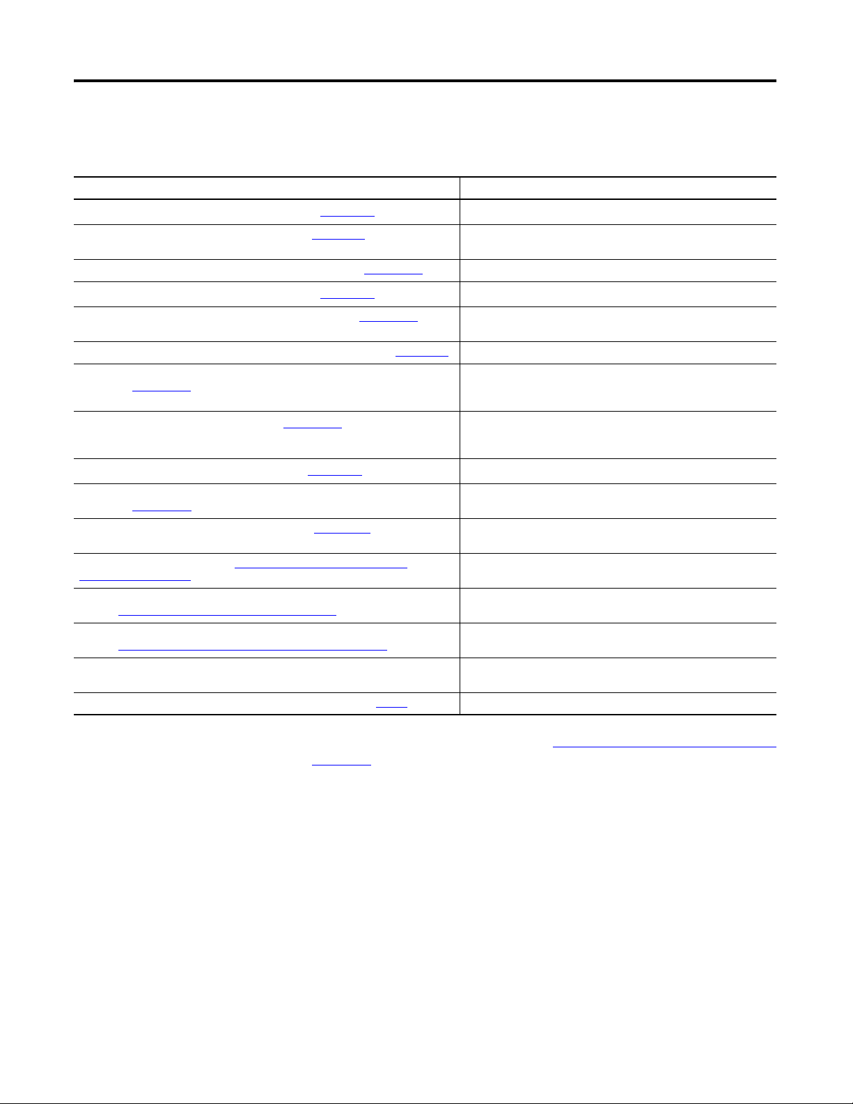
Topic Pages
Chapter 5 - Configuring the Kinetix 3 Drive added. 221…297
Appendix A - Ultraware Software Updates adds Version 1.80 notes. 339
Rockwell Automation Publication 2098-UM001G-EN-P - February 2011 3
Page 4

Summary of Changes
4 Rockwell Automation Publication 2098-UM001G-EN-P - February 2011
Page 5

Table of Contents
Preface
Before You Begin
About This Publication. . . . . . . . . . . . . . . . . . . . . . . . . . . . . . . . . . . . . . . . . . . 11
Who Should Use this Manual . . . . . . . . . . . . . . . . . . . . . . . . . . . . . . . . . . . . . 11
Conventions Used in This Manual . . . . . . . . . . . . . . . . . . . . . . . . . . . . . . . . 11
Additional Resources . . . . . . . . . . . . . . . . . . . . . . . . . . . . . . . . . . . . . . . . . . . . . 12
Chapter 1
Introduction. . . . . . . . . . . . . . . . . . . . . . . . . . . . . . . . . . . . . . . . . . . . . . . . . . . . . 13
About Ultraware Software . . . . . . . . . . . . . . . . . . . . . . . . . . . . . . . . . . . . . . . . 13
Download Ultraware Software . . . . . . . . . . . . . . . . . . . . . . . . . . . . . . . . . . . . 14
Using Online Help . . . . . . . . . . . . . . . . . . . . . . . . . . . . . . . . . . . . . . . . . . . . . . . 14
How Ultraware Software Works . . . . . . . . . . . . . . . . . . . . . . . . . . . . . . . . . . 14
Understanding the Graphical User Interface. . . . . . . . . . . . . . . . . . . . . . . . 15
Workspace Window. . . . . . . . . . . . . . . . . . . . . . . . . . . . . . . . . . . . . . . . . . 16
Output Window . . . . . . . . . . . . . . . . . . . . . . . . . . . . . . . . . . . . . . . . . . . . . 17
Client Area . . . . . . . . . . . . . . . . . . . . . . . . . . . . . . . . . . . . . . . . . . . . . . . . . . 18
Main Menubar . . . . . . . . . . . . . . . . . . . . . . . . . . . . . . . . . . . . . . . . . . . . . . . 19
Toolbars . . . . . . . . . . . . . . . . . . . . . . . . . . . . . . . . . . . . . . . . . . . . . . . . . . . . . 19
Status Bar. . . . . . . . . . . . . . . . . . . . . . . . . . . . . . . . . . . . . . . . . . . . . . . . . . . . 20
Motion Library Dialog . . . . . . . . . . . . . . . . . . . . . . . . . . . . . . . . . . . . . . . 20
Starting Ultraware Software. . . . . . . . . . . . . . . . . . . . . . . . . . . . . . . . . . . . . . . 21
Opening an Ultraware File . . . . . . . . . . . . . . . . . . . . . . . . . . . . . . . . . . . . 21
Serial Port Settings . . . . . . . . . . . . . . . . . . . . . . . . . . . . . . . . . . . . . . . . . . . 22
Upgrading Drive Firmware . . . . . . . . . . . . . . . . . . . . . . . . . . . . . . . . . . . . . . . 22
Common Commands for Ultra
Drive Configuration
Chapter 2
Introduction. . . . . . . . . . . . . . . . . . . . . . . . . . . . . . . . . . . . . . . . . . . . . . . . . . . . . 23
Opening Ultraware Software . . . . . . . . . . . . . . . . . . . . . . . . . . . . . . . . . . . . . . 24
Creating, Opening and Saving Ultraware Files . . . . . . . . . . . . . . . . . . . . . . 25
Creating a New Ultraware File . . . . . . . . . . . . . . . . . . . . . . . . . . . . . . . . 25
Opening an Existing Ultraware File . . . . . . . . . . . . . . . . . . . . . . . . . . . . 26
Saving an Ultraware File . . . . . . . . . . . . . . . . . . . . . . . . . . . . . . . . . . . . . . 27
Creating a New Drive . . . . . . . . . . . . . . . . . . . . . . . . . . . . . . . . . . . . . . . . . . . . 28
Importing and Exporting a Drive . . . . . . . . . . . . . . . . . . . . . . . . . . . . . . . . . . 28
Exporting a Drive. . . . . . . . . . . . . . . . . . . . . . . . . . . . . . . . . . . . . . . . . . . . . 28
Importing a Drive . . . . . . . . . . . . . . . . . . . . . . . . . . . . . . . . . . . . . . . . . . . . 29
Working in the Workspace Window . . . . . . . . . . . . . . . . . . . . . . . . . . . . . . 30
Cut . . . . . . . . . . . . . . . . . . . . . . . . . . . . . . . . . . . . . . . . . . . . . . . . . . . . . . . . . 30
Copy . . . . . . . . . . . . . . . . . . . . . . . . . . . . . . . . . . . . . . . . . . . . . . . . . . . . . . . . 31
Paste . . . . . . . . . . . . . . . . . . . . . . . . . . . . . . . . . . . . . . . . . . . . . . . . . . . . . . . . 31
Delete . . . . . . . . . . . . . . . . . . . . . . . . . . . . . . . . . . . . . . . . . . . . . . . . . . . . . . . 32
Drag and Drop . . . . . . . . . . . . . . . . . . . . . . . . . . . . . . . . . . . . . . . . . . . . . . . 33
Rockwell Automation Publication 2098-UM001G-EN-P - February 2011 5
Page 6

Table of Contents
Chapter 3
Configuring the Ultra3000 Drive
Introduction . . . . . . . . . . . . . . . . . . . . . . . . . . . . . . . . . . . . . . . . . . . . . . . . . . . . . 37
Configuring the Ultra3000 Drive . . . . . . . . . . . . . . . . . . . . . . . . . . . . . . . . . . 38
Configuring Properties for the Ultra3000 Drive . . . . . . . . . . . . . . . . . 39
Understanding the Ultra3000 Drive Branch . . . . . . . . . . . . . . . . . . . . . . . . 41
Velocity Control Panel Window . . . . . . . . . . . . . . . . . . . . . . . . . . . . . . . 50
Current Control Panel Window . . . . . . . . . . . . . . . . . . . . . . . . . . . . . . . 52
Current Control Panel Window . . . . . . . . . . . . . . . . . . . . . . . . . . . . . . . 52
Indexing Control Panel . . . . . . . . . . . . . . . . . . . . . . . . . . . . . . . . . . . . . . . 54
Drive Report . . . . . . . . . . . . . . . . . . . . . . . . . . . . . . . . . . . . . . . . . . . . . . . . . 57
Switching the SERCOS Interface . . . . . . . . . . . . . . . . . . . . . . . . . . . . . . 58
Understanding the Analog Window . . . . . . . . . . . . . . . . . . . . . . . . . . . . . . . 59
Understanding the Preset Window . . . . . . . . . . . . . . . . . . . . . . . . . . . . . . . . 62
Understanding the Follower Window. . . . . . . . . . . . . . . . . . . . . . . . . . . . . . 64
Understanding the Indexing Window. . . . . . . . . . . . . . . . . . . . . . . . . . . . . . 66
Understanding the Homing Window . . . . . . . . . . . . . . . . . . . . . . . . . . . . . . 70
Understanding the Motor Window . . . . . . . . . . . . . . . . . . . . . . . . . . . . . . . . 73
Understanding the Tuning Window . . . . . . . . . . . . . . . . . . . . . . . . . . . . . . . 77
Autotuning Window . . . . . . . . . . . . . . . . . . . . . . . . . . . . . . . . . . . . . . . . . 80
Manual Position Tuning Window . . . . . . . . . . . . . . . . . . . . . . . . . . . . . 82
Manual Velocity Tuning Window . . . . . . . . . . . . . . . . . . . . . . . . . . . . . 84
Understanding the Encoders Window . . . . . . . . . . . . . . . . . . . . . . . . . . . . . 86
Motor Diagnostics . . . . . . . . . . . . . . . . . . . . . . . . . . . . . . . . . . . . . . . . . . . . 89
Understanding the Digital Inputs Window . . . . . . . . . . . . . . . . . . . . . . . . . 95
Understanding the Digital Outputs Window . . . . . . . . . . . . . . . . . . . . . . . 99
Understanding the Analog Outputs Window . . . . . . . . . . . . . . . . . . . . . . 103
Understanding the Monitor . . . . . . . . . . . . . . . . . . . . . . . . . . . . . . . . . . . . . . 105
Understanding the Oscilloscope Window . . . . . . . . . . . . . . . . . . . . . . . . . 108
Channel Setup Window. . . . . . . . . . . . . . . . . . . . . . . . . . . . . . . . . . . . . . 111
Understanding Ultra3000 with DeviceNet . . . . . . . . . . . . . . . . . . . . . . . . 112
Understanding Ultra3000 Status . . . . . . . . . . . . . . . . . . . . . . . . . . . . . . . . . 118
Understanding the Faults Window . . . . . . . . . . . . . . . . . . . . . . . . . . . . . . . 126
Understanding the Service Information Window . . . . . . . . . . . . . . . . . . 135
6 Rockwell Automation Publication 2098-UM001G-EN-P - February 2011
Page 7

Chapter 4
Table of Contents
Configuring the Ultra5000 Drive
Introduction. . . . . . . . . . . . . . . . . . . . . . . . . . . . . . . . . . . . . . . . . . . . . . . . . . . . 137
Configuring the Ultra5000 Drive. . . . . . . . . . . . . . . . . . . . . . . . . . . . . . . . . 138
Configuring Properties for the Ultra5000 Drive . . . . . . . . . . . . . . . 139
Understanding the Ultra5000 Drive Branch. . . . . . . . . . . . . . . . . . . . . . . 141
Installing Drivers . . . . . . . . . . . . . . . . . . . . . . . . . . . . . . . . . . . . . . . . . . . . 145
Drive Report . . . . . . . . . . . . . . . . . . . . . . . . . . . . . . . . . . . . . . . . . . . . . . . . 145
Understanding the Motion Branch . . . . . . . . . . . . . . . . . . . . . . . . . . . . . . . 146
Understanding the Jog Window. . . . . . . . . . . . . . . . . . . . . . . . . . . . . . . . . . 147
Understanding the Move Window . . . . . . . . . . . . . . . . . . . . . . . . . . . . . . . 149
Understanding the Cam Window . . . . . . . . . . . . . . . . . . . . . . . . . . . . . . . . 151
Inserting a Cam Table . . . . . . . . . . . . . . . . . . . . . . . . . . . . . . . . . . . . . . . 154
Importing a Cam Table . . . . . . . . . . . . . . . . . . . . . . . . . . . . . . . . . . . . . . 154
Importing a CSV File . . . . . . . . . . . . . . . . . . . . . . . . . . . . . . . . . . . . . . . . 154
Cam Table branch . . . . . . . . . . . . . . . . . . . . . . . . . . . . . . . . . . . . . . . . . . . . . . 155
Cam Table Editor . . . . . . . . . . . . . . . . . . . . . . . . . . . . . . . . . . . . . . . . . . . 155
Understanding the Gear Window . . . . . . . . . . . . . . . . . . . . . . . . . . . . . . . . 161
Understanding the Motor Window. . . . . . . . . . . . . . . . . . . . . . . . . . . . . . . 163
Understanding the Tuning Window. . . . . . . . . . . . . . . . . . . . . . . . . . . . . . 168
Autotuning Window . . . . . . . . . . . . . . . . . . . . . . . . . . . . . . . . . . . . . . . . 172
Understanding the Encoders Window . . . . . . . . . . . . . . . . . . . . . . . . . . . . 175
Understanding the Digital Inputs Window. . . . . . . . . . . . . . . . . . . . . . . . 180
Understanding the Digital Outputs Window. . . . . . . . . . . . . . . . . . . . . . 182
Understanding the Analog Inputs Window . . . . . . . . . . . . . . . . . . . . . . . 184
Understanding the Analog Outputs Window. . . . . . . . . . . . . . . . . . . . . . 186
Understanding the Oscilloscope Window . . . . . . . . . . . . . . . . . . . . . . . . . 188
Channel Setup Window . . . . . . . . . . . . . . . . . . . . . . . . . . . . . . . . . . . . . 190
Understanding Ultra5000 with DeviceNet . . . . . . . . . . . . . . . . . . . . . . . . 193
Monitoring Your Ultra5000 Drive . . . . . . . . . . . . . . . . . . . . . . . . . . . . . . . 196
Ultra5000 Status. . . . . . . . . . . . . . . . . . . . . . . . . . . . . . . . . . . . . . . . . . . . . . . . 199
Understanding the Programs Branch . . . . . . . . . . . . . . . . . . . . . . . . . . . . . 205
Understanding the Archives Branch . . . . . . . . . . . . . . . . . . . . . . . . . . . . . . 205
Understanding the Files Branch . . . . . . . . . . . . . . . . . . . . . . . . . . . . . . . . . . 206
Understanding the Global Variables Branch . . . . . . . . . . . . . . . . . . . . . . . 206
Creating a new Global Variable . . . . . . . . . . . . . . . . . . . . . . . . . . . . . . . 207
Editing an Existing Global Variable . . . . . . . . . . . . . . . . . . . . . . . . . . . 208
Understanding the Faults Window . . . . . . . . . . . . . . . . . . . . . . . . . . . . . . . 210
Understanding the Service Information Window . . . . . . . . . . . . . . . . . . 217
Rockwell Automation Publication 2098-UM001G-EN-P - February 2011 7
Page 8

Table of Contents
Chapter 5
Configuring the Kinetix 3 Drive
Introduction . . . . . . . . . . . . . . . . . . . . . . . . . . . . . . . . . . . . . . . . . . . . . . . . . . . . 221
Configuring the Kinetix 3 Drive . . . . . . . . . . . . . . . . . . . . . . . . . . . . . . . . . . 222
Configuring Properties for the Kinetix 3 Drive . . . . . . . . . . . . . . . . 222
Understanding the Kinetix 3 Drive Branch . . . . . . . . . . . . . . . . . . . . . . . . 225
Velocity Control Panel Window . . . . . . . . . . . . . . . . . . . . . . . . . . . . . . 234
Using the Setup Wizard . . . . . . . . . . . . . . . . . . . . . . . . . . . . . . . . . . . . . . 236
Understanding the Analog Window . . . . . . . . . . . . . . . . . . . . . . . . . . . . . . 237
Understanding the Preset Window . . . . . . . . . . . . . . . . . . . . . . . . . . . . . . . 239
Understanding the Follower Window. . . . . . . . . . . . . . . . . . . . . . . . . . . . . 241
Understanding the Indexing Window. . . . . . . . . . . . . . . . . . . . . . . . . . . . . 243
Understanding the Homing Window . . . . . . . . . . . . . . . . . . . . . . . . . . . . . 246
Understanding the Motor Window . . . . . . . . . . . . . . . . . . . . . . . . . . . . . . . 249
Understanding the Tuning Window . . . . . . . . . . . . . . . . . . . . . . . . . . . . . . 253
Autotuning Window . . . . . . . . . . . . . . . . . . . . . . . . . . . . . . . . . . . . . . . . 258
Manual Position Tuning Window . . . . . . . . . . . . . . . . . . . . . . . . . . . . 260
Manual Velocity Tuning Window . . . . . . . . . . . . . . . . . . . . . . . . . . . . 262
Understanding the Encoders Window . . . . . . . . . . . . . . . . . . . . . . . . . . . . 265
Understanding the Digital Inputs Window . . . . . . . . . . . . . . . . . . . . . . . . 267
Understanding the Digital Outputs Window . . . . . . . . . . . . . . . . . . . . . . 271
Understanding the Analog Outputs Window . . . . . . . . . . . . . . . . . . . . . . 274
Understanding the Monitor Window . . . . . . . . . . . . . . . . . . . . . . . . . . . . . 275
Monitor Setup Window. . . . . . . . . . . . . . . . . . . . . . . . . . . . . . . . . . . . . . 276
Understanding the Oscilloscope Window . . . . . . . . . . . . . . . . . . . . . . . . . 278
Channel Setup Window. . . . . . . . . . . . . . . . . . . . . . . . . . . . . . . . . . . . . . 281
Understanding Kinetix 3 Status Displays . . . . . . . . . . . . . . . . . . . . . . . . . . 282
Understanding the Faults Window . . . . . . . . . . . . . . . . . . . . . . . . . . . . . . . 287
Understanding the Fault Detail Window . . . . . . . . . . . . . . . . . . . . . . . . . . 296
Understanding the Service Information Window . . . . . . . . . . . . . . . . . . 297
8 Rockwell Automation Publication 2098-UM001G-EN-P - February 2011
Page 9

Chapter 6
Table of Contents
Creating and Running Programs
Introduction. . . . . . . . . . . . . . . . . . . . . . . . . . . . . . . . . . . . . . . . . . . . . . . . . . . . 299
Using a Project Branch . . . . . . . . . . . . . . . . . . . . . . . . . . . . . . . . . . . . . . . . . . 299
Creating a New Project . . . . . . . . . . . . . . . . . . . . . . . . . . . . . . . . . . . . . . 299
Configuring a Project . . . . . . . . . . . . . . . . . . . . . . . . . . . . . . . . . . . . . . . . 300
Executing Project Commands . . . . . . . . . . . . . . . . . . . . . . . . . . . . . . . . 302
Using Source Files. . . . . . . . . . . . . . . . . . . . . . . . . . . . . . . . . . . . . . . . . . . . . . . 303
Creating a New Source File . . . . . . . . . . . . . . . . . . . . . . . . . . . . . . . . . . 303
Renaming a Source File . . . . . . . . . . . . . . . . . . . . . . . . . . . . . . . . . . . . . . 303
Using Header Files . . . . . . . . . . . . . . . . . . . . . . . . . . . . . . . . . . . . . . . . . . . . . . 305
Creating a New Header File . . . . . . . . . . . . . . . . . . . . . . . . . . . . . . . . . . 305
Renaming a Header File. . . . . . . . . . . . . . . . . . . . . . . . . . . . . . . . . . . . . . 305
Executing Source or Header File Commands . . . . . . . . . . . . . . . . . . 306
Using the Motion Library Dialog. . . . . . . . . . . . . . . . . . . . . . . . . . . . . . . . . 307
Using the Text Editor . . . . . . . . . . . . . . . . . . . . . . . . . . . . . . . . . . . . . . . . . . . 309
Find . . . . . . . . . . . . . . . . . . . . . . . . . . . . . . . . . . . . . . . . . . . . . . . . . . . . . . . . 309
Find Next. . . . . . . . . . . . . . . . . . . . . . . . . . . . . . . . . . . . . . . . . . . . . . . . . . . 310
Replace . . . . . . . . . . . . . . . . . . . . . . . . . . . . . . . . . . . . . . . . . . . . . . . . . . . . . 310
Select All . . . . . . . . . . . . . . . . . . . . . . . . . . . . . . . . . . . . . . . . . . . . . . . . . . . 311
Go To Corresponding { } ( ). . . . . . . . . . . . . . . . . . . . . . . . . . . . . . . . . . 311
Go To Line Number. . . . . . . . . . . . . . . . . . . . . . . . . . . . . . . . . . . . . . . . . 312
Bookmarks. . . . . . . . . . . . . . . . . . . . . . . . . . . . . . . . . . . . . . . . . . . . . . . . . . 312
Show Line Numbers . . . . . . . . . . . . . . . . . . . . . . . . . . . . . . . . . . . . . . . . . 315
Wildcard Search Characters . . . . . . . . . . . . . . . . . . . . . . . . . . . . . . . . . . 316
Replace . . . . . . . . . . . . . . . . . . . . . . . . . . . . . . . . . . . . . . . . . . . . . . . . . . . . . 316
Select All . . . . . . . . . . . . . . . . . . . . . . . . . . . . . . . . . . . . . . . . . . . . . . . . . . . 318
Undo. . . . . . . . . . . . . . . . . . . . . . . . . . . . . . . . . . . . . . . . . . . . . . . . . . . . . . . 318
Redo . . . . . . . . . . . . . . . . . . . . . . . . . . . . . . . . . . . . . . . . . . . . . . . . . . . . . . . 319
Using Executable Program Files . . . . . . . . . . . . . . . . . . . . . . . . . . . . . . . . . . 320
Creating a Program . . . . . . . . . . . . . . . . . . . . . . . . . . . . . . . . . . . . . . . . . . 320
Configuring a Program. . . . . . . . . . . . . . . . . . . . . . . . . . . . . . . . . . . . . . . 320
Executable Program File Commands . . . . . . . . . . . . . . . . . . . . . . . . . . 321
Importing and Exporting Files. . . . . . . . . . . . . . . . . . . . . . . . . . . . . . . . . . . . 323
Exporting Projects, Header Files and Source Files . . . . . . . . . . . . . . 323
Importing Projects, Header Files, and Source Files. . . . . . . . . . . . . . 324
Executing Your Program. . . . . . . . . . . . . . . . . . . . . . . . . . . . . . . . . . . . . . . . . 325
Run (Program) . . . . . . . . . . . . . . . . . . . . . . . . . . . . . . . . . . . . . . . . . . . . . . 325
Stop (Program). . . . . . . . . . . . . . . . . . . . . . . . . . . . . . . . . . . . . . . . . . . . . . 325
Kill (Program) . . . . . . . . . . . . . . . . . . . . . . . . . . . . . . . . . . . . . . . . . . . . . . 326
Using Direct Commands . . . . . . . . . . . . . . . . . . . . . . . . . . . . . . . . . . . . . . . . 327
Rockwell Automation Publication 2098-UM001G-EN-P - February 2011 9
Page 10

Table of Contents
Chapter 7
Creating Custom Motors
Ultraware Software Updates
Introduction . . . . . . . . . . . . . . . . . . . . . . . . . . . . . . . . . . . . . . . . . . . . . . . . . . . . 331
Accessing the Motor Database . . . . . . . . . . . . . . . . . . . . . . . . . . . . . . . . . . . . 331
Creating Custom Motor Parameter Sets . . . . . . . . . . . . . . . . . . . . . . . . . . . 332
Motor Database . . . . . . . . . . . . . . . . . . . . . . . . . . . . . . . . . . . . . . . . . . . . . . . . . 333
Using the Linear Motor Window . . . . . . . . . . . . . . . . . . . . . . . . . . . . . . . . . 335
Using the Rotary Motor Window. . . . . . . . . . . . . . . . . . . . . . . . . . . . . . . . . 337
Importing Motors . . . . . . . . . . . . . . . . . . . . . . . . . . . . . . . . . . . . . . . . . . . . . . . 338
Exporting Motors . . . . . . . . . . . . . . . . . . . . . . . . . . . . . . . . . . . . . . . . . . . . . . . 338
Appendix A
Introduction . . . . . . . . . . . . . . . . . . . . . . . . . . . . . . . . . . . . . . . . . . . . . . . . . . . . 339
Version 1.80 . . . . . . . . . . . . . . . . . . . . . . . . . . . . . . . . . . . . . . . . . . . . . . . . . . . . 339
Kinetix 3 Drive-related Enhancements . . . . . . . . . . . . . . . . . . . . . . . . 339
General Enhancements. . . . . . . . . . . . . . . . . . . . . . . . . . . . . . . . . . . . . . . 339
Version 1.64 . . . . . . . . . . . . . . . . . . . . . . . . . . . . . . . . . . . . . . . . . . . . . . . . . . . . 339
Ultra3000 Drive-related Enhancements . . . . . . . . . . . . . . . . . . . . . . . 339
Version 1.63 . . . . . . . . . . . . . . . . . . . . . . . . . . . . . . . . . . . . . . . . . . . . . . . . . . . . 339
Ultra3000 Drive-related Enhancements . . . . . . . . . . . . . . . . . . . . . . . 339
Ultra5000 Drive-related Enhancements . . . . . . . . . . . . . . . . . . . . . . . 339
Version 1.60 . . . . . . . . . . . . . . . . . . . . . . . . . . . . . . . . . . . . . . . . . . . . . . . . . . . . 340
Ultra1500 Drive-related Enhancements . . . . . . . . . . . . . . . . . . . . . . . 340
Ultra3000 Drive-related Enhancements . . . . . . . . . . . . . . . . . . . . . . . 340
Ultra5000 Drive-related Enhancements . . . . . . . . . . . . . . . . . . . . . . . 340
General Enhancements. . . . . . . . . . . . . . . . . . . . . . . . . . . . . . . . . . . . . . . 340
Help File Enhancements . . . . . . . . . . . . . . . . . . . . . . . . . . . . . . . . . . . . . 340
Version 1.50 . . . . . . . . . . . . . . . . . . . . . . . . . . . . . . . . . . . . . . . . . . . . . . . . . . . . 342
Ultra3000 Drive-related Enhancements . . . . . . . . . . . . . . . . . . . . . . . 342
Ultra5000 Drive-related Enhancements . . . . . . . . . . . . . . . . . . . . . . . 342
General . . . . . . . . . . . . . . . . . . . . . . . . . . . . . . . . . . . . . . . . . . . . . . . . . . . . . 343
Version 1.40 . . . . . . . . . . . . . . . . . . . . . . . . . . . . . . . . . . . . . . . . . . . . . . . . . . . . 343
Ultra3000 Drive-related Enhancements . . . . . . . . . . . . . . . . . . . . . . . 343
Ultra5000 Drive-related Enhancements . . . . . . . . . . . . . . . . . . . . . . . 343
General Enhancements . . . . . . . . . . . . . . . . . . . . . . . . . . . . . . . . . . . . . . 344
Version 1.30 . . . . . . . . . . . . . . . . . . . . . . . . . . . . . . . . . . . . . . . . . . . . . . . . . . . . 344
Ultra3000 Drive-related Enhancements . . . . . . . . . . . . . . . . . . . . . . . 344
Ultra5000 Drive-related Enhancements . . . . . . . . . . . . . . . . . . . . . . . 345
General Enhancements. . . . . . . . . . . . . . . . . . . . . . . . . . . . . . . . . . . . . . . 345
Installation Notes . . . . . . . . . . . . . . . . . . . . . . . . . . . . . . . . . . . . . . . . . . . . . . . 346
10 Rockwell Automation Publication 2098-UM001G-EN-P - February 2011
Page 11

Preface
About This Publication
Who Should Use this Manual
Conventions Used in This Manual
This manual provides detailed installation instructions, defines software interface
features, and programming assistance for Ultraware software.
Use this manual when Ultraware software release 1.8 is used to configure and
operate Ultra1500, Ultra3000, Ultra5000 and Kinetix 3 drives, or when
designing, testing or running ModBus, C language programs, or cam tables on
these drives.
The conventions listed below are used throughout this manual.
• Bulleted lists such as this one provide information, not procedural steps
• Numbered lists provide sequential steps or hierarchical information
Rockwell Automation Publication 2098-UM001G-EN-P - February 2011 11
Page 12
Additional Resources
These documents contain additional information concerning related
Rockwell Automation products.
Resource Description
Ultra3000 Hardware Installation Manual, publication 2098
Ultra3000 SERCOS Integration Manual, publication 2098-IN005
Ultra3000 DSD with DeviceNet Reference Manual, publication 2098-RM001 Object models for Ultra3000 DeviceNet applications.
Ultra5000 Hardware Installation Manual, publication 2098
Ultra5000 IPD with DeviceNet Reference Manual, publication 2098-RM002
Kinetix 3 Component Servo Drive Installation Instructions, publication 2071-IN001 Information on installing your Kinetix 3 drive system.
Kinetix 3 Component Servo Drive Serial Host Command Reference Manual,
publication 2071-RM001
Ultraware Programming Manual, publication 2098
-IN003
How to configure the Ultra3000 SERCOS interface hardware with
-IN001
How to configure and monitor the Ultra5000 drive using the
-PM001
Ultra3000 drive installation and programming procedures.
the ControlLogix SERCOS module.
Ultra5000 drive installation and programming procedures.
DeviceNet interface.
Information on the serial communication commands, both ASCII and
ModBus-RTU, for interfacing a motion controller with the Kinetix 3
drive.
Information on programming the Ultra5000 using the Ultraware
programming environment. Intended for programmers with a basic
understanding of the C programming language.
Ultraware CD Installation Instructions, publication 2098
System Design for Control of Electrical Noise Reference Manual,
publication GMC-RM001
Kinetix Motion Control Selection Guide, publication GMC-SG001 Specifications, motor/servo-drive system combinations, and
Motion Analyzer CD, download at http://www.ab.com/motion/software/
analyzer_download.html
Rockwell Automation Configuration and Selection Tools,
website http://www.rockwellautomation.com/en/e-tools
Rockwell Automation Product Certification,
website http://www.rockwellautomation.com/products/certification
National Electrical Code, published by the National Fire Protection Association of
Boston, MA
Rockwell Automation Industrial Automation Glossary, publication AG-7.1
-IN002 Instructions for installing Ultraware software
Information, examples, and techniques designed to minimize
system failures caused by electrical noise.
accessories for Kinetix motion control products.
Drive and motor sizing with application analysis software.
Online product selection and system configuration tools, including
AutoCAD (DXF) drawings.
Website for declarations of conformity (DoC) currently available
from Rockwell Automation.
An article on wire sizes and types for grounding electrical
equipment.
A glossary of industrial automation terms and abbreviations.
You can view or download publications at http://www.rockwellautomation.com/
literature/. To order paper copies of technical documentation, contact your local
Rockwell Automation distributor or sales representative.
12 Rockwell Automation Publication 2098-UM001G-EN-P - February 2011
Page 13

Before You Begin
Chapter
1
Introduction
About Ultraware Software
Use this chapter to become familiar with Ultraware software components.
This chapter also reviews design and installation requirements for Ultraware
software.
Topic Page
Introduction 13
About Ultraware Software 13
About Ultraware Software 13
Using Online Help 14
How Ultraware Software Works 14
Understanding the Graphical User Interface 15
Starting Ultraware Software 21
Upgrading Drive Firmware 22
Ultraware software is a Windows 95/98/2000/NT/XP application by Rockwell
Automation that provides a programming environment for the Kinetix 3,
Ultra1500, Ultra3000, and Ultra5000 drives. You can use Ultraware software to
accomplish these tasks.
• Communicate with multiple drives, using the serial port on your computer.
• Adjust the feedback loop gains and parameters of your drive for specific
motors and loads.
• Define the motion capabilities of the drive with the operating modes and
motion functions from compatible drives.
• Configure I/O for the drives.
• Write, load, and execute C language motion programs for Ultra5000
drives.
• Monitor a wide variety of status and motion parameters on the drives.
• Customize the application interface to display only the information you
wish to see.
Rockwell Automation Publication 2098-UM001G-EN-P - February 2011 13
Page 14

Chapter 1 Before You Begin
Download Ultraware Software
Using Online Help
To communicate and configure your Kinetix 3 drive by using serial
communication from a personal computer, download and install Ultraware
software on your personal computer. To get the latest Ultraware software follow
these steps.
1. Navigate to http://www.ab.com/motion/software/get/
Ultraware_1_80.exe.
2. Click Run.
The following types of online help are available.
To use this Do this Description
Help files Click Contents and Index from
the Help menu. Navigate the
help files using the Table of
Contents, the Index and the
Search tabs.
Context Sensitive Help files Click Help in the active window,
or
Click an on-screen object and
press F1.
Descriptions of all on-screen
objects.
Object property configuration
settings.
How to information.
For help about the selected
object.
How Ultraware Software Works
You can also click the Tip of the Day command from the Help menu, which
opens a dialog box that displays helpful hints on using Ultraware software.
Ultraware software is one part of a motion control system. The user commands
the Ultraware software to:
• use a compiler/linker tool to produce executable programs.
• communicate with the drive through a separate Communication library.
• use the Communication library to:
– download program and configuration information,
– execute direct commands, and
– retrieve program, configuration, and status information.
At startup you see several work areas that let you perform tasks. For example, you
can create or edit Ultra5000 programs in a text editor, using the C programming
language.
14 Rockwell Automation Publication 2098-UM001G-EN-P - February 2011
Page 15
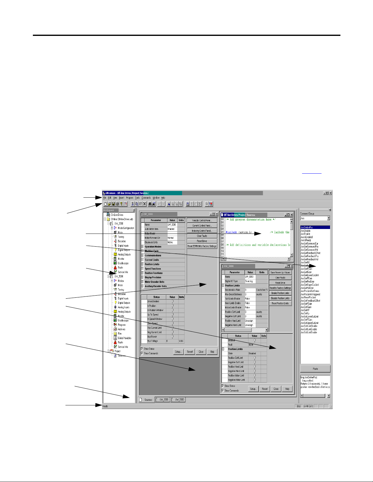
Before You Begin Chapter 1
Main menubar
Status bar
Output window
Workspace window
Client area
Properties windows
Ultra3000
Ultra5000
Toolbars
Editor windows
Motion Library dialog
Understanding the Graphical User Interface
A graphical user interface lets you to configure your drives and run your program.
The workspace consists of the pre-defined areas listed below and shown in the
diagram.
• a Workspace window
• a Client Area
• an Output window
• a Main menubar
• a set of Toolbars
• a Status bar
Use the View menu commands to enable and disable the user interface features.
The user interface for drives is shown in the example. The example depicts the
common control and command groupings for the drives listed on page 13
as
compatible with Ultraware software.
Rockwell Automation Publication 2098-UM001G-EN-P - February 2011 15
Page 16
Chapter 1 Before You Begin
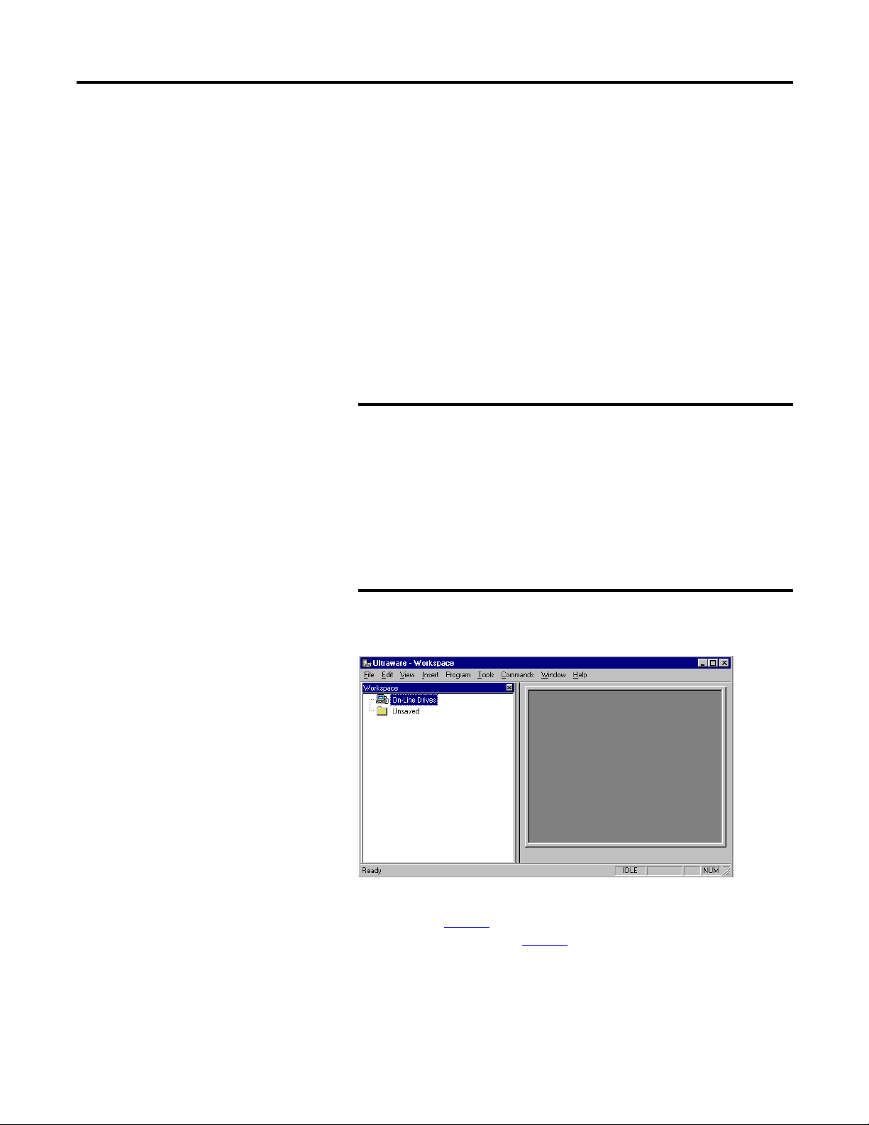
Workspace Window
The Workspace window is, by default, beneath the menubar and toolbars, and
above the Status Bar. Use the F7 key to return focus to the Workspace window.
The Workspace window has two main branches.
Branch Description of Display
On-Line Drives branch All connected online drives and their child objects.
File branch All configured offline Ultra3000 and Ultra5000 drives, their child
objects and available projects (including all child source, header
and executable files)
Use the Workspace window to navigate to all of the connected online and offline
objects and perform these tasks.
• Create new Drive, Folder, Project, Header, and Source files.
• Cut, Copy, Paste, and Delete Workspace window objects.
• Open the Properties dialog box for Workspace window objects.
• Copy or create cam table files, which you can edit or graphically modify.
• Open the text editor, which you can use to edit header and source files.
• Use the Build command to compile a Project and create an executable
program (.exe) file.
• Copy or Move an executable program (.exe) file from an Ultra5000 drive's
Projects branch to a Programs branch for storage or for execution.
• Copy a configured online drive with all its children from the On-Line
Drives branch, to an offline file, or vice-versa.
• Run an executable program (.exe) file in the Programs branch of an online
Ultra5000 drive.
• Issue direct commands for certain online drive objects.
You can resize and move the Workspace window in several ways.
• In its default state attached to the interface, you can double-click the title
bar to detach the Workspace window from the interface.
• If detached, the Workspace window possesses all of the properties of any
window. It can be resized or moved entirely outside the interface.
• To return the Workspace window to its default position, double-click the
title bar.
To hide the Workspace window, remove the checkmark from the Workspace in
the View menu.
16 Rockwell Automation Publication 2098-UM001G-EN-P - February 2011
Page 17

Before You Begin Chapter 1
Output Window
The Output window is, by default, beneath the Workspace window above the
Status Bar. The Output window is visible when the View menu's Output
command is active (denoted by a check mark); it is hidden when the Output
command is not active. The Output window is also visible when you execute the
Program menu’s Build command.
The Output window describes the progress of the current (or most recent) Build
command. If a Build succeeds, the Output window displays the message Build
completed successfully!. If a Build fails, the Output window displays the message
Build failed. along with an fault message describing the cause of the failure.
Ultraware software removes any pre-existing executable program (.exe.) file,
bearing the project name, if a Build fails.
When a Build fails, double-click the Output window fault message with the this
format.
<Filename>:<Line number>:<fault or warning message>
This will open the associated source or header file and position the cursor at the
line referenced by the fault or warning message.
You can resize and move the Output window in several ways.
• In its default state (attached to the interface) you can double-click the title
bar to detach the Output window from the interface.
• Once detached, the Output window possesses all the properties of any
window. It can be resized or moved entirely outside the interface.
• To return the Output window to its default position, double-click the title
bar.
You can copy text in the Output window. However, you cannot type text into the
Output window.
Rockwell Automation Publication 2098-UM001G-EN-P - February 2011 17
Page 18

Chapter 1 Before You Begin
Client Area
The Client Area is the large gray area beneath the menubar and toolbars and to
the right of the Workspace window.
Use the Client Area to display:
• property windows for objects in the Workspace window, where you can
configure the object’s properties.
• text editor windows for header and source files in the Workspace window,
where you can create or edit these text files.
The Workbook Mode in the View menu displays a tab for each object in the
Client Area. The tab contains the abbreviated name of the related object. Click a
tab to bring the related object to the top of the Client Area.
Unlike windows, the Client Area cannot be directly resized. The size of the
Client Area depends upon the size and location of the surrounding Workspace
and Output windows, the Main menubar, the Status Bar and the several toolbars.
However, you can use the Cascade, Tile Wide, Tile Tall and Arrange Icons
Window menu commands to arrange the display of windows in the client area.
18 Rockwell Automation Publication 2098-UM001G-EN-P - February 2011
Page 19
Before You Begin Chapter 1
Main Menubar
The Main menubar is at the top of the interface. Use it to customize the main
window, and to perform essential functions and procedures with respect to
objects in the Main Window.
The main menubar looks like this.
The menu items contain these commands.
Menu Name Contains these Commands
File New, Open, Save, Save As, Close, Print, Print Preview, Print Setup, Import,
Edit Undo, Redo, Cut, Copy, Paste, Delete, Find, Go To Corresponding { } ( ),
View Toolbars, Status Bar, Workspace, Output, Workbook Mode, Motion Library
Insert
Export, Upgrade Firmware, Exit
Go To Line Number, Replace, Select All, Toggle Bookmark, Next Bookmark,
Previous Bookmark, Clear All Bookmarks, Properties
Ultra3000, Ultra5000, Project, Source File, Header File, Variable, Cam Table
Program Build, Run, Stop, Kill
Tools Customize, Rescan, Serial Port, Recover Communications
Commands Enabled, other direct commands
Window Close All, Cascade, Tile Wide, Tile Tall, Arrange Icons
Help
Contents and Index, Tip Of The Day, Release Notes, About Ultraware
Rockwell Automation Publication 2098-UM001G-EN-P - February 2011 19
Page 20
Chapter 1 Before You Begin
Toolbars
Four standard Windows toolbars can be detached from the user interface and
relocated. To return a toolbar to its last docking position, double-click the header
bar.
Toolbar Name Contains these Commands
File New, Open, Save, Print, About, Locate
Edit Cut, Copy, Paste, Erase, Find, Find Next, Undo, Redo, Toggle Bookmark, Next
Bookmark, Previous Bookmark, Clear All Bookmarks
Program Build, Run, Stop, Kill
Enable Enable, Disable All
Use the Toolbars command (in the View menu) to open the Toolbars dialog box,
and enable or disable existing toolbars, and create new toolbars.
Use the Customize command (in either the Toolbars dialog box or the Tools
menu) to open the Customize dialog box, where you can:
• add a command icon to a toolbar by dragging it from the Command tab
and dropping it on the desired toolbar.
• delete a command icon from a toolbar by dragging it from a toolbar and
dropping it off the toolbar.
Status Bar
To display the Status bar, use the View menu Status Bar command. The status bar
contains:
• Tooltip help - a description of the menu or button command immediately
beneath the pointer.
• indicators for caps lock (CAP), num lock (NUM) and scroll lock (SCRL).
• row and column reference for the cursor, if a source file or header file has
focus in the Text Editor.
When the status bar is visible, a check mark appears to the left of the Status Bar
command in the View menu.
Motion Library Dialog
The Ultraware Motion Library dialog lets you to quickly find and insert specific
motion library commands and C statements in a motion program.
The Motion Library is displayed when a source or header file is open; and is
hidden when source and header files are closed or not the top view windows. The
Motion Library dialog is docked to the right side of the main window by default.
20 Rockwell Automation Publication 2098-UM001G-EN-P - February 2011
Page 21

Before You Begin Chapter 1
TIP
Starting Ultraware Software
When you start the software for the first time, it prompts you to Open Last File,
xxx.udb, Open existing file, or Create new file. After you click the file to open or
create, the software scans the network for online drives.
You may need to configure your PC’s serial port settings (refer to Serial Port
Settings on page 22
page 21
) to verify that the software successfully locates all online network drives.
) and rescan the network (refer to Scanning the Network on
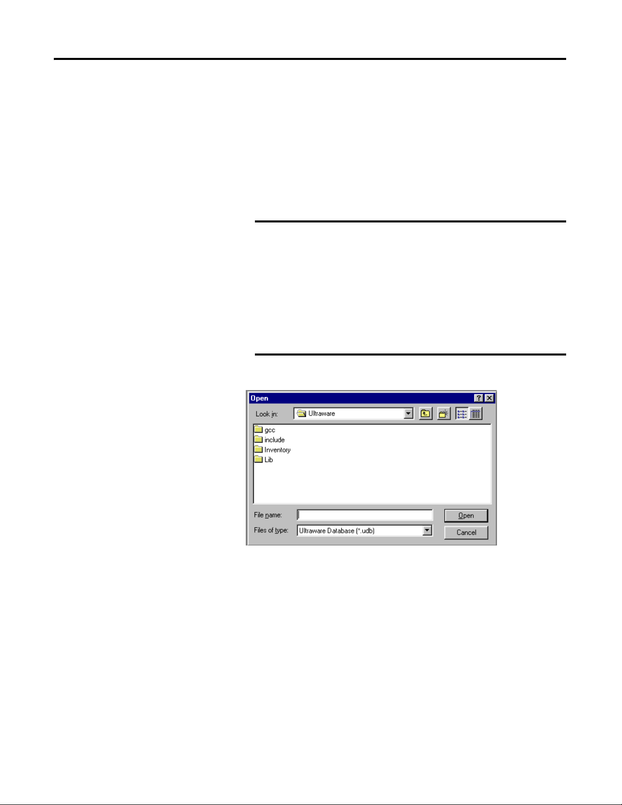
Opening an Ultraware File
The name and location of any open file is stored in memory, when you close your
software. Each time the software opens, it displays a dialog that lets you do one of
these commands.
Select Description
Open Last File, xxx.udb, and then OK Opens the most recently used Ultraware file.
Open existing file, and then OK Open another, existing Ultraware file of your choice.
Create new file, and then OK Open a new Ultraware file.
Cancel Open Ultraware without an active file in the Workspace
window.
A new file is held in temporary storage until saved.
Scanning the Network
When the software opens, it conducts a search of the network for all connected
drives. The Scan For On-Line Drives dialog displays the progress of the online
node scan (0…255), and the specific task the software is currently undertaking
(for example, Scanning Node or Attaching to Node).
Click Stop Scanning to stop the scanning for and attaching to online drives.
The On-Line Drives branch of the Workspace window displays each drive
detected. Because the software does not automatically update the Workspace
window, click Rescan from the Tools menu to display the list of drives that are
currently online.
Rockwell Automation Publication 2098-UM001G-EN-P - February 2011 21
Page 22

Chapter 1 Before You Begin
IMPORTANT
IMPORTANT
Serial Port Settings
After you open the software for the first time, you may change the configuration
of the personal computer’s serial port and baud rate settings. The default settings
are COM1 and 38400. Perform these steps to change the settings.
1. Click Serial Port from the Tools menu.
2. In the PC Communications Setup dialog box, type the appropriate serial
port settings.
Ultra5000 drives support only the format 8 data bits, no parity.
Ultra3000 drives do not support the 57600 bps rate.
Upgrading Drive Firmware
You can use the software interface to upgrade the firmware for an online drive.
Use the Upgrade Firmware command (in the File menu) to open the Firmware
Upgrade dialog box, where you can perform a flash upgrade to the firmware of a
drive appearing in the On-Line Drives branch of the Workspace window. Before
issuing the Upgrade Firmware command, be sure to first obtain a copy of the new
firmware and any related instructions.
Perform these steps to upgrade firmware in the Firmware Upgrade dialog box.
1. Click the drive for firmware upgrade from the list of On-Line Drives. If a
drive name has been left blank, it is identified as <Unnamed Drive>.
2. Enter the pathname of the new firmware file. Either type in the pathname,
or use the browse button (marked with an ellipsis) to navigate to the new
firmware file. (The new firmware file must have an extension of .hex.)
3. Click Begin Load. The software informs you of firmware upgrade progress
using both a progress bar and status messages.
Click Cancel to stop the firmware upgrade. However, If you cancel the
firmware upgrade while it is in progress, the selected drive ceases to be
functional. Thereafter, the selected drive can be used only to complete a
subsequent firmware upgrade.
If drivers are to be installed, also see Installing Drivers on page 145
22 Rockwell Automation Publication 2098-UM001G-EN-P - February 2011
.
Page 23

Chapter
Common Commands for Ultra Drive
Configuration
2
Introduction
This chapter describes show to configure both an online and an offline drive. It
also describes how to copy or move it to an offline Ultraware file, or how to copy
and paste an offline drive (in an Ultraware file) onto an existing online drive,
thereby overwriting the online drive’s settings. It also explains how to use dragand-drop to accomplish the copy and paste process in a single step.
Topic Page
Introduction 23
Opening Ultraware Software 24
Creating, Opening and Saving Ultraware Files 25
Creating a New Drive 28
Importing and Exporting a Drive 28
Working in the Workspace Window 30
Rockwell Automation Publication 2098-UM001G-EN-P - February 2011 23
Page 24
Chapter 2 Common Commands for Ultra Drive Configuration
TIP
Opening Ultraware Software
Before you create a new offline drive, you must first create an Ultraware file to
contain the new drive. When Ultraware opens for the first time, a window similar
to the one below appears. Selecting any radio button causes the action described
below.
• Click Open Last File: <filename> and then click OK to open the most
recently used Ultraware file.
• Click Open existing file and then click OK. The Open window will
appear, and you can navigate to and open a previously saved Ultraware file.
• Click Create new file and then click OK to create a new, empty file.
A new file is stored in temporary storage, and the Workspace icon
displays Unsaved until the file is saved with a filename.
• Click Cancel to exit the window without opening an Ultraware file.
The selected Ultraware file, if any, is displayed in an Off-Line branch of the
Workspace window.
24 Rockwell Automation Publication 2098-UM001G-EN-P - February 2011
Page 25
Common Commands for Ultra Drive Configuration Chapter 2
IMPORTANT
Creating, Opening and Saving Ultraware Files
An Ultraware file is a container that can hold any number or combination of
offline Ultra3000 and Ultra5000 drives, projects and their children. An
Ultraware file is distinguished by its extension of .udb.
Creating a New Ultraware File
To create a new Ultraware DataBase (.udb) file, perform these steps.
1. Open an Ultraware file using one of these options:
• Click New in the File menu.
• Click the New icon in the File toolbar.
• Press the Ctrl + N keys.
If an Ultraware file is already open, a Save Changes window
opens and requires a response before the request to open a new
file executes.
Choose one of these commands.
• Yes - Saves the open file under the filename in the designated
location. Saves the open file under the filename in the
designated location.
• No - Discards the changes to the open file.
• Cancel - Aborts the new Ultraware file, leaving the previous
file open.
2. A new Ultraware file, titled Unsaved, appears in the Workspace under On-
Line Drives.
3. The Ultraware file can be populated with drives as described in Creating a
New Drive on page 28
Saving an Ultraware File on page 27
, and saved under a name using the directions in
.
Rockwell Automation Publication 2098-UM001G-EN-P - February 2011 25
Page 26
Chapter 2 Common Commands for Ultra Drive Configuration
IMPORTANT
Opening an Existing Ultraware File
To open an existing Ultraware file, perform these steps.
1. Open an existing Ultraware file using one of these options:
• Click Open in the File menu.
• Click the Open icon in the File toolbar.
• Press the Ctrl + O keys.
Yes
If an Ultraware file is already open, a Save Changes window
opens and requires a response before the request to open a new
file executes.
Choose one of these commands.
• Yes - Saves the open file under the filename in the designated
location. Saves the open file under the filename in the
designated location.
• No - Discards the changes to the open file.
• Cancel - Aborts the new Ultraware file, leaving the previous
file open.
2. Perform these steps in the Open dialog box.
a. Navigate to and click the name of the Ultraware file to open.
b. Click Open.
The selected Ultraware file appears in the Workspace window. If the
Workspace window displayed a previously opened Ultraware file, the
selected Ultraware file is displayed.
26 Rockwell Automation Publication 2098-UM001G-EN-P - February 2011
Page 27
Common Commands for Ultra Drive Configuration Chapter 2
TIP
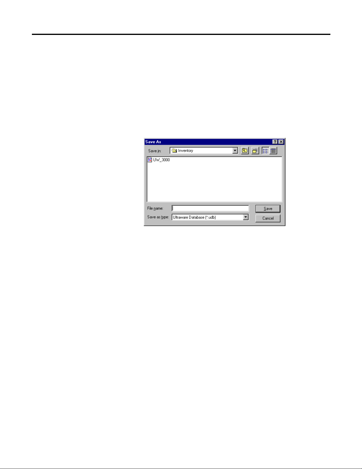
Saving an Ultraware File
To save all changes made to a drive or a project, perform these steps.
1. Choose one of these options.
• Click Save in the File menu
• Click the Save icon in the File toolbar
• Press the Ctrl + S keys
2. Click Save As in the File menu to open the Save As dialog box.
3. Type or click a file name in the Save As dialog box.
4. Navigate to the location where the new Ultraware file should be stored.
5. Click Save.
Save As saves the entire Ultraware database (.udb) file to a
new name.
Rockwell Automation Publication 2098-UM001G-EN-P - February 2011 27
Page 28
Chapter 2 Common Commands for Ultra Drive Configuration
Creating a New Drive
Importing and Exporting a Drive
With an Ultraware file open in the Workspace window, you can add a new offline
Ultra3000, Ultra5000, or Kinetix 3 drive.
To add a new drive, perform these steps.
• Click Ultra1500, Ultra3000, Ultra5000, or Kinetix 3 in the Insert Menu.
• Right-click the Ultraware file, and then-click the drive type (Kinetix 3,
Ultra1500, Ultra3000, Ultra5000).
A new drive appears in the Workspace window.
The name of the new drive is Drive or (if Drive already exists) Driven, where n is
the lowest positive integer that creates a unique drive name for the specific drive
model. For example, two 2098-DSD-005 drives may be named Drive and Drive1,
and two 2098-DSD-005X drives may also be named Drive and Drive 1.
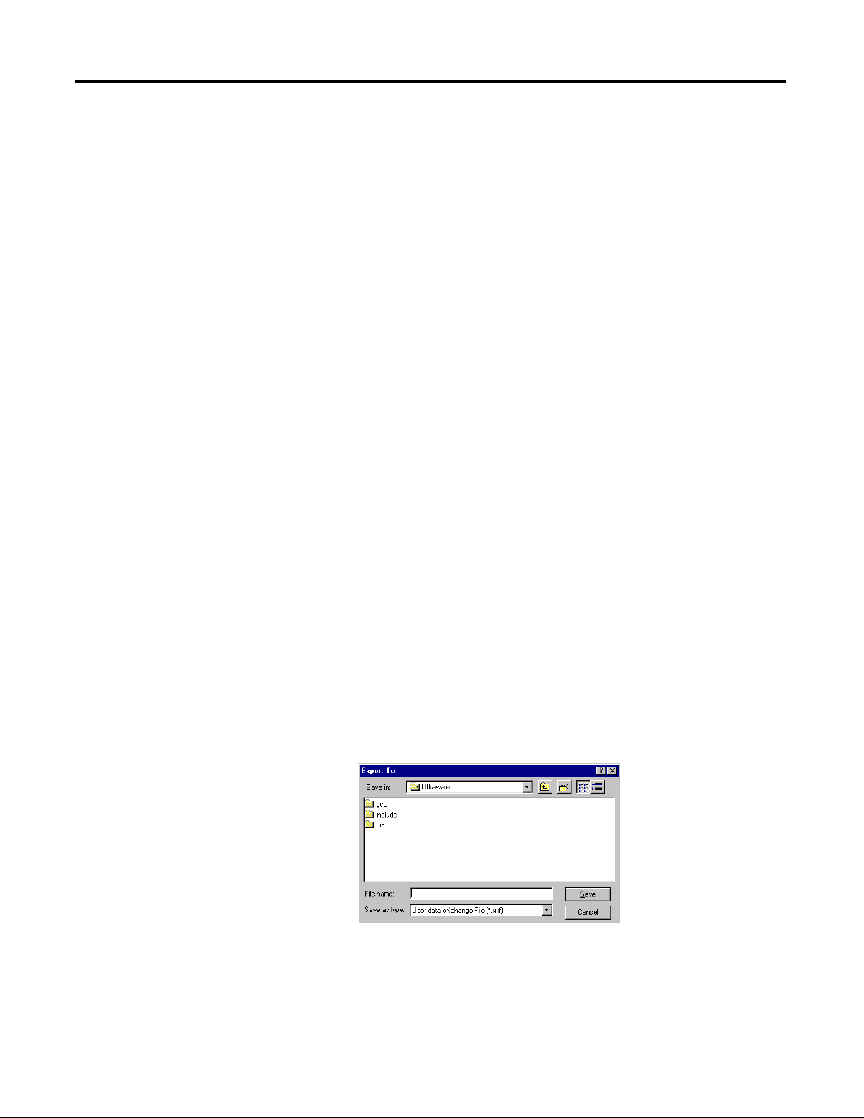
You can import an existing, previously configured drive to an Ultraware file using
the File menu’s Import command.
Only drives that have been previously exported, using the File menu’s Export
command, can be imported. Exporting a drive saves it as an User data eXchange
File with a .uxf extension.
Exporting a Drive
To Export a drive, perform these steps.
1. Click a drive branch.
2. Do one of these actions to open the Export To dialog box.
• Click Export in the File menu.
• Right-click the drive branch, and click Export in the menu.
3. Type or click a name for the drive in the Export To dialog box.
4. Navigate to a location where the file should be exported.
5. Click Save.
The exported file is saved as an User data eXchange File (with an .uxf extension).
28 Rockwell Automation Publication 2098-UM001G-EN-P - February 2011
Page 29
Common Commands for Ultra Drive Configuration Chapter 2
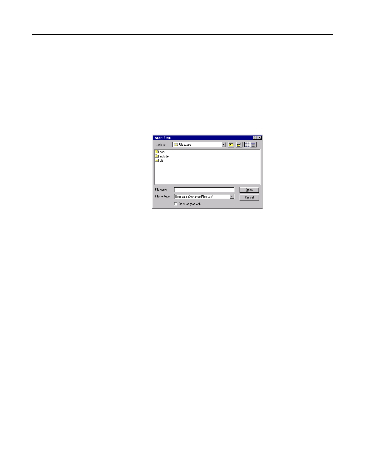
Importing a Drive
To Import a previously exported drive, performs these steps.
1. Click the offline Ultraware file.
2. Do one of these actions to open the The Import From window.
• Click Import in the File menu.
• Right-click the Ultraware file, and then click Import from the pop-up
menu.
3. In the Import From window, navigate to and click the User data eXchange
File (.uxf) that contains the desired drive settings.
4. Click Open to display the imported drive in the offline Ultraware file.
Rockwell Automation Publication 2098-UM001G-EN-P - February 2011 29
Page 30

Chapter 2 Common Commands for Ultra Drive Configuration
Working in the Workspace Window
You can use the Edit menu commands to Cut, Copy, Paste and Delete/Erase
items in the Workspace window. You can also use a Drag and Drop function in
place of Cut and Paste.
Cut
The Cut command removes selected items from the Workspace window. Any
item cut from the Workspace window replaces any other item previously cut (or
copied) and stored on the clipboard.
These Workspace window items cannot be cut.
• an On-Line Drives branch
• a drive in the On-Line Drives branch
• an Ultraware file
• any child branch of a drive
• a program (with an .exe extension) for a project in an offline Ultraware file
To Cut an item from the Workspace window, perform these steps.
1. Click a Workspace window item (other than one of those listed above).
2. Do one of these actions.
• Click Cut in the Edit menu.
• Click Cut from the pop-up menu.
• Simultaneously press the Ctrl + X keys.
• Click the Cut icon in the Edit toolbar.
3. A message box asks you if you wish to continue. Click OK to cut or
Cancel.
30 Rockwell Automation Publication 2098-UM001G-EN-P - February 2011
Page 31

Common Commands for Ultra Drive Configuration Chapter 2
Copy
The Copy command copies selected items from the Workspace window. Any
branch or item copied in the Workspace window replaces any other branch or
item previously copied (or cut) and stored in the clipboard.
The following Workspace window items cannot be copied:
• An Ultraware file
• Child branches of a drive.
To copy an item in the Workspace window, perform these steps.
1. Click a Workspace window item (other than one of those listed above).
2. Do one of these actions.
• Click Copy in the Edit menu.
• Right-click on a drive in the Workspace window, then click Copy from
the pop-up menu.
• Simultaneously press the Ctrl + C keys.
• Click the Copy icon in the Edit toolbar.
Paste
The Paste command inserts a previously copied or cut Workspace window item
or branch into the selected location of the Workspace window.
When pasting into the Workspace window, three results can occur:
• If the selected Workspace window item is of the same type as the item to be
pasted, the pasted item replaces the selected item.
• If the selected Workspace window item is a parent branch that must always
have one child of the same type as the item to be pasted, the pasted item
replaces the selected branch's child of the same type.
• If the selected Workspace window branch can have multiple child branches
of the same type as the item to be pasted, the pasted item:
– replaces a child branch with the same name as the pasted item, or
– is added as an additional child branch, if no other child branch shares
the pasted item's name.
Any Workspace window item can be selected to receive a pasted item, except
these items:
• a source (.c) file
• a header (.h) file
• child branches of an Ultra3000 drive.
• some child branches of an Ultra5000 drive
Rockwell Automation Publication 2098-UM001G-EN-P - February 2011 31
Page 32

Chapter 2 Common Commands for Ultra Drive Configuration
IMPORTANT
To paste an item in the Workspace window, perform these steps.
1. Click a Workspace window branch in which to paste the item.
2. Do one of these actions.
• Click Paste in the Edit menu.
• Click on a branch drive in the Workspace window, then right-click
• Click Paste from the pop-up menu.
• Simultaneously press the Ctrl + V keys.
• Click the Paste icon in the Edit toolbar.
The Workspace window branch selected can not be any of these
branch types.
• an on-line drive
• a child project in the archives
• a source (.c) file
• a header (.h) file
• a child or the children of an Ultra3000 drive
Paste from the pop-up menu.
If you are pasting an item into the Workspace window that replaces
another item of the same name, a message box asks if you wish to continue.
3. Click OK to paste, or Cancel to quit.
Delete
The Delete command removes selected branches or items from the Workspace
window. The deleted item is permanently destroyed. The Delete command
cannot be reversed by an Undo command.
These Workspace window items cannot be deleted.
• an On-Line Drives branch
• a drive in the On-Line Drives branch
• an Ultraware file
• an immediate child item branching directly from a drive
• an executable program child (with an .exe extension) of an offline project
To delete an item from the Workspace window, perform these steps.
1. Click a Workspace window item (other than one of those listed above).
2. Do one of these commands.
• Click Delete in the Edit menu.
• Click Delete in the pop-up.
32 Rockwell Automation Publication 2098-UM001G-EN-P - February 2011
Page 33

Common Commands for Ultra Drive Configuration Chapter 2
• Click the Erase icon in the Edit toolbar.
3. Click OK to delete or Cancel in the message box that appears.
Drag and Drop
You can use the drag-and-drop method to copy and move a Workspace window
branch or item to other locations within the Workspace window. The drag-anddrop method combines the Cut, Copy and Paste commands, as follows:
• the drag-and-drop method copies a Workspace window branch or item
that can be both copied using the Copy command, and pasted using the
Paste command.
• the drag-and-drop method moves a Workspace window branch or item
that can be both cut using the Cut command, and pasted using the Paste
command.
To use the drag-and-drop method to copy a Workspace window branch or item:
1. Place the cursor arrow on a Workspace window branch or item that can be
copied and hold down the left mouse button.
2. Drag the selected Workspace window branch or item to the desired
destination. One of two things happens:
• If the item can be copied, the pointer continues to appear as an arrow
and a + (plus) sign appears to the right of the arrow (for as long as you
continue drag the item over a place in the Workspace window where it
may be dropped).
• If the item cannot be copied, or if you are dragging the item over a part
of the Workspace window where it may not be dropped, the arrow is
replaced by a circle with a line through it.
3. Release the mouse button when you arrive at the Workspace window
location where you want to copy the Workspace window branch or item.
The result is the same as if you had Copied then Pasted it to this location.
To use the drag-and-drop method to move a Workspace window or item:
1. Place the cursor arrow on a Workspace window or item that can be cut and
hold down both the left mouse button and the Ctrl key.
2. Drag the selected Workspace window or item to the desired destination.
One of two things occurs:
• If the item can be cut, the pointer continues to appear as an arrow (for
as long as you continue drag the item over a place in the Workspace
window where it may be dropped).
• If the item cannot be cut, or if you are dragging the item over a part of
the Workspace window where it may not be dropped, the arrow is
replaced by a circle with a line through it.
Rockwell Automation Publication 2098-UM001G-EN-P - February 2011 33
Page 34

Chapter 2 Common Commands for Ultra Drive Configuration
3. When you arrive at the Workspace window location where you want to
move the item, release both the mouse button and the Ctrl key. The result
is the same as if you had Cut then Pasted it to this location.
34 Rockwell Automation Publication 2098-UM001G-EN-P - February 2011
Page 35

Configuring the Ultra3000 Drive
Chapter
3
Introduction
This chapter describes how to configure your Ultra3000 drive to an operational
mode.
Also described are these Ultra3000 drive interface options:
• homing
• oscilloscope
• drive tuning
• drive monitoring
• motor and encoder diagnostic routines
Topic Page
Introduction 37
Configuring the Ultra3000 Drive 38
Understanding the Ultra3000 Drive Branch 41
Understanding the Analog Window 59
Understanding the Preset Window 62
Understanding the Follower Window 64
Understanding the Indexing Window 66
Understanding the Homing Window 70
Understanding the Motor Window 73
Understanding the Tuning Window 77
Understanding the Encoders Window 86
Understanding the Digital Inputs Window 95
Understanding the Digital Outputs Window 99
Understanding the Analog Outputs Window 103
Understanding the Monitor 105
Understanding the Oscilloscope Window 108
Understanding Ultra3000 with DeviceNet 112
Understanding Ultra3000 Status 118
Understanding the Faults Window 126
Understanding the Service Information Window 135
Rockwell Automation Publication 2098-UM001G-EN-P - February 2011 37
Page 36

Chapter 3 Configuring the Ultra3000 Drive
Configuring the Ultra3000 Drive
Each Ultra3000 drive in the Workspace window has these child branches or
windows:
• Operation Modes
– Analog
– Preset
– Follower
– Indexing
– Homing
Indexing and Homing operation modes are available only for drive types
whose catalog numbers end in X (for example, 2098-DSD-005X).
• Motor
• Tu n i n g
• Encoders
• Digital Inputs
• Digital Outputs
• Analog Outputs
• Monitor
• Oscilloscope
• Faults
• DeviceNet
• Service Information
Except for the Monitor windows, all of a drive’s child branches can and must be
configured in a Properties window.
38 Rockwell Automation Publication 2098-UM001G-EN-P - February 2011
Page 37

Configuring the Ultra3000 Drive Chapter 3
TIP
Configuring Properties for the Ultra3000 Drive
To configure the properties for an Ultra3000 drive or one of its child branches,
perform these steps.
1. In the Workspace window, click the drive branch to configure.
2. Do one of these:
• Click Properties from the Edit menu.
• Right-click the drive in the Workspace, and click Export from the pop-
up menu.
• Double-click the drive branch.
If the drive is a SERCOS drive, only those parameters, status and
direct commands appropriate for a SERCOS drive are displayed.
A Properties window, such as the Drive Properties window displayed
below, appears for the selected drive branch.
Rockwell Automation Publication 2098-UM001G-EN-P - February 2011 39
Page 38

Chapter 3 Configuring the Ultra3000 Drive
3. To configure properties for the selected drive branch, use the features of
the Properties window as follows.
Section Description
Parameters Located in the upper left part of the Properties window. Type or
Commands Located in the upper right part of the Properties window. Click any
Status Located beneath the Parameters and Commands sections. By
Show Status Displays status for the drive branch.
Show Commands Displays commands for the drive branch. Commands can be
Setup Opens the Monitor Setup window, where you can customize the
Revert Returns parameter settings to the values they had when you first
Close Closes the window.
Help Displays online help for this window.
click settings in the parameter fields to configure the drive branch.
button to issue the associated command. Click Show Commands,
below, to display command buttons. Not every drive branch has
associated commands.
default, these fields display the online status of the selected drive
branch. Click Setup to open a window where you can customize the
status to be displayed. Status fields are read-only. Click Show
Status to display the status section.
Note: Status values for offline drives may not be meaningful.
executed only for online drives. This selection is dimmed if no
commands are associated with the selected drive branch.
status display.
Refer to
Understanding the Monitor on page 105 for more
information about using the Monitor window.
opened this window.
The remainder of this chapter describes the process of entering and editing drive
configuration settings, the status are displayed by default for each drive branch
when the drive is online, and the commands available to a user for each drive
branch when the drive is online.
40 Rockwell Automation Publication 2098-UM001G-EN-P - February 2011
Page 39

Configuring the Ultra3000 Drive Chapter 3
Understanding the Ultra3000 Drive Branch
The Properties window for the Ultra3000 Drive branch looks like this.
Rockwell Automation Publication 2098-UM001G-EN-P - February 2011 41
Page 40

Chapter 3 Configuring the Ultra3000 Drive
Use this Ultra3000 window to:
• configure the parameters for an offline or an online drive
• monitor the status of an online drive
• execute commands that clear faults, reset the drive or reset the EEPROM
• open the Control Panel windows, where you can issue commands that
control drive motion
If the drive is a SERCOS drive, with its SERCOS interface active, the drive is
displayed with a small “S” next to the drive icon. The software displays a custom
workspace tree and property windows, limiting the display appropriately for a
SERCOS drive.
You can edit parameters for both an online and an offline drive. However, you
can monitor status and execute direct commands (executed through the
Ultraware interface) only for an Ultra3000 drive in the On-Line Drives branch.
The following parameters apply to the Ultra3000 Drive window.
Parameter Description
Name The name of the drive, up to 32 characters long.
Note: The drive name is displayed in the title bar of the windows
relating to this drive.
Auto Motor Iden Select:
Motor Model The model of the motor to be controlled by the drive. Selecting a
Motor Forward Dir Click either:
Displayed Units Click a unit of measure for position, velocity, and acceleration
Operation Modes
• Enabled: Causes the drive to read motor parameters from an
intelligent encoder, or
• Disabled: Causes the drive to read motor parameters from a
Motor Model selected, below.
motor model from the drop-down list sets its parameters in the
Motor window.
Note: For an online drive, you must disable the drive before you
can edit its Motor Model parameter.
Note: Ultraware software ships with a utility that lets you create
custom motor configurations. Use that utility to add customized
motor selections to the Motor Model list.
• Normal: a positive direction move increases the encoder count.
• Reverse: a positive direction move decreases the encoder
count.
displays:
Metric:
• units for rotary motors are: counts (position), rpm (velocity), rpm
per second
• units for linear motors are: meters (position), meter per second
(velocity), and meter per second
English:
• units for rotary motors are: counts (position), rpm (velocity), rpm
per second2 (acceleration);
• units for linear motors are: inches (position), inches per second
(velocity), and inches per second2 (acceleration).,
User: displays measurements in terms defined by the user in the
Units section, below.
2
(acceleration);
2
(acceleration).
42 Rockwell Automation Publication 2098-UM001G-EN-P - February 2011
Page 41

Configuring the Ultra3000 Drive Chapter 3
Parameter Description
Operation Mode The drive's command source.
Note: An online drive must be disabled before you can edit its
Operation Mode parameter.
Selections include:
• Analog Current Input: a +/- 10 volt analog input provides the
current command.
• Analog Position: a +/- 10 volt analog input provides the position
command.
• Analog Velocity Input: a +/- 10 volt analog input provides the
velocity command.
• Follower: Auxiliary Encoder: a quadrature encoder provides a
position command signal input to the drive.
• Follower: Step/Direction Input: Step and Direction inputs
provide a position command signal input to the drive.
• Follower: Step Up/Step Down Input: Step Up and Step Down
inputs provide a position command signal input to the drive.
• Indexing: (only for Indexing drives) Up to 64 indexes can be
configured in the Indexing window. The combination of Preset
Select Lines 0, 1, 2, 3, 4 and 5, in the Digital Inputs window,
determines the Index (0 – 63) that is selected.
Refer to Understanding the Digital Inputs Window on page 95
for more information about how to assign a Preset Select Line
to a Digital Input.
• Preset Current: a preset Current provides the current command.
Up to 8 Preset Current values can be set in the Preset window.
The combination of Preset Select Lines 0, 1 and 2 in the Digital
Inputs window, determines the Preset Current (0 – 7) that is
selected.
Refer to
Understanding the Digital Inputs Window on page 95
for more information about how to assign Preset Select Line
functions to a Digital Input.
• Preset Position: a preset Position provides the position
command. Up to 8 Preset Position values can be set in the
Preset window. The combination of Preset Select Lines 0, 1 and
2 in the Digital Inputs window, determines the Preset Position
(0 – 7) that is selected.
Understanding the Digital Inputs Window on page 95
Refer to
for more information about how to assign a Preset Select Line
to a Digital Input.
• Preset Velocity: a Preset Velocity provides the velocity
command. Up to 8 Preset Velocity values can be set in the
Preset window. The combination of Preset Select Lines 0, 1 and
2 in the Digital Inputs window, determines the Preset Velocity
(0 – 7) that is used for the velocity command.
Refer to
Understanding the Digital Inputs Window on page 95
for more information about how to assign Preset Select Line
functions to a Digital Input.
Operation Mode Override The connected drive's command source that is used when the
Operation Mode Override input is active. The Operation Mode
Override input is assigned to a digital input in the Digital Inputs
window.
Note: See Operation Mode, above, for an explanation of the
available selections.
Rockwell Automation Publication 2098-UM001G-EN-P - February 2011 43
Page 42

Chapter 3 Configuring the Ultra3000 Drive
Parameter Description
Machine Cycle
Enable or disable a Single-Turn Absolute encoder.
• Enabled: to cause the SRS encoder to be used as an absolute
feedback device
• Disabled: to cause the SRS encoder not to be used as an
absolute feedback device. (Default)
Note: This parameter is visible only if the offline motor selection
or online motor has an SRS/SRM encoder.
Enable or disable Position Rollover:
• Enabled: to cause the position variable to rollover to zero when
it exceeds the specified size. (Default)
• Disabled: to cause the position variable to rollover only when it
exceeds 2147483647 counts, or its equivalent in other units.
Note: This parameter is disabled when Single-Turn Absolute is
enabled.
Size: Type a rollover value in counts. This is an integer at which
the next increment of a position variable will be the value of zero
(0).
Note: This parameter is disabled when Single-Turn Absolute is
enabled, and is automatically set to one revolution.
Communications
Drive Address The drive's communication port address - an integer from 0 to 255
Broadcast Address The address used by a host PC or PLC to issue a single broadcast
Baud Rate Baud rate setting for the drive.
Frame Format Specify the drive's communication port packet framing format.
- used in multiple axis applications. For single axis applications,
this value is usually set to 0. The drive must be reset before it
recognizes an edited drive address.
Note: Communication port parameters can be set in the PC
Communications Setup dialog box, that is opened using the Tools
menu Serial Port command.
command to all connected Ultra3000 drives. The drive does not
send a response to commands received with the broadcast
address.
Note: If a drive's Broadcast Address and Drive Address are set to
the same value, that drive treats all commands as normal, pointto-point commands, and sends a response to all commands it
processes.
Note: The drive's Baud Rate must be the same as the PC's Baud
Rate (set in the PC Communications Setup dialog box) if the PC
and drive are to successfully communicate.
Serial Port Settings on page 22 for restrictions.
Refer to
Note: The drive's Frame Format must be the same as the PC's
Format (set in the PC Communications Setup dialog box) if the PC
and drive are to successfully communicate.
44 Rockwell Automation Publication 2098-UM001G-EN-P - February 2011
Page 43

Configuring the Ultra3000 Drive Chapter 3
Parameter Description
Current Limits
Positive The drive's positive current limit value.
Note: The value entered here is divided by the lesser of
intermittent drive current rating and intermittent current rating of
the motor, and is stored on the drive as a percentage. If a different
motor is selected for the drive, with a different current capacity,
this parameter value changes.
During runtime, the drive limits positive current to the lesser of:
• the Positive Current Limit (this value),
• the analog current limit Input (an analog input of the drive that
limits current proportionately to its value),
• the Intermittent Current rating of the drive (a fixed value, hard-
coded into the drive), or
• the Intermittent Current rating of the motor (stored in the motor
database).
Negative The drive's negative current limit runtime value.
Note: The value entered here is divided by the lesser of
intermittent drive current rating and intermittent current rating of
the motor, and is stored on the drive as a percentage. If a different
motor is selected for the drive, with a different current capacity,
this parameter value changes.
During runtime, the drive limits negative current to the lesser of:
• the Negative Current Limit (this value),
• the analog current limit Input (an analog input of the drive that
limits current proportionately to its value),
• the Intermittent Current rating of the drive (a fixed value, hard-
coded into the drive), or
• the Intermittent Current rating of the motor (stored in the motor
database).
Position Limits
Positive Decel Distance The stopping distance used when the drive encounters a positive
Negative Decel Distance The stopping distance used when the drive encounters a negative
Enable Soft Limits Select:
Positive Soft Limit If the motor feedback position is greater than this value, the drive
Negative Soft Limit If the motor feedback position is less than this value, the drive has
Speed Functions
Zero Speed This value creates a plus or minus (+/-) range, or window, around
In Speed Window This value creates a plus or minus (+/-) range, or window, around
Up to Speed This value sets a velocity level. If the motor feedback velocity is
overtravel limit.
overtravel limit.
• On: Causes the drive to compare the motor feedback position to
the Positive and Negative Soft Limits to determine if the drive
has exceeded an overtravel limit.
• Off: Turns off software overtravel limit checking.
has exceeded the soft overtravel limit.
exceeded the soft overtravel limit.
the zero velocity. If the motor feedback velocity falls within this
range, the Zero Speed flag is (or remains) set.
Note: You can assign the Zero Speed, In Speed Window or Up To
Speed flags to digital outputs and control execution of your
process based on the state of these flags.
the programmed velocity. If the motor feedback velocity falls
within this range, the In Speed Window flag is (or remains) set.
greater than or equal to this value, the Up To Speed flag is (or
remains) set.
Rockwell Automation Publication 2098-UM001G-EN-P - February 2011 45
Page 44

Chapter 3 Configuring the Ultra3000 Drive
Parameter Description
Position Functions
In Position Size The maximum amount of position error that permits the In Position
and the In Position Window flags to be (or remain) set.
In Position Time The minimum length of time the position error must be less than
the In Position Size value, for the In Position and the In Position
Window flags to be (or remain) set.
Posn Compare 1 Type Specify the type of comparison that will determine if the Posn
Compare 1 flag should be set. Either:
• Greater Than: the flag will be set if the motor feedback position
is greater than the Posn Compare 1 value.
• Less Than: the flag will be set if the motor feedback position is
less than the Posn Compare 1 value.
• Within Window: the flag will be set if the motor feedback
position is greater than Posn Compare 1 Min and less than
Posn Compare 1 Max.
• Outside Window: the flag will be set if the motor feedback
position is less than Posn Compare 1 Min or more than Posn
Compare 1 Max.
Note: This parameter is supported in firmware revision 1.29 and
higher.
Posn Compare 1 Enter the position, in counts, that is compared to the motor
feedback position to determine if the Posn Compare 1 flag should
be set.
Posn Compare 1 Min Enter the minimum position, in counts, that will be compared to
the motor feedback position to determine if the Posn Compare 1
flag should be set.
Note: Displayed if Posn Compare 1 Type is set to Within Window
or Outside Window.
Posn Compare 1 Max Enter the maximum position, in counts, that will be compared to
the motor feedback position to determine if the Posn Compare 1
flag should be set.
Note: Displayed if Posn Compare 1 Type is set to Within Window
or Outside Window.
Posn Compare 1 Polarity The type of comparison that determines if the Posn Compare 1
flag should be set. Either:
• Greater Than: the flag is set if the motor feedback position is
greater than the Posn Compare 2 value.
• Less Than: the flag is set if the motor feedback position is less
than the Posn Compare 2 value.
Note: Replaced with Posn Compare 1 Type starting with firmware
revision 1.29.
Posn Compare 2 Type The type of comparison that will determine if the Posn Compare 2
flag should be set. Either:
• Greater Than: the flag will be set if the motor feedback position
is greater than the Posn Compare 2 value.
• Less Than: the flag will be set if the motor feedback position is
less than the Posn Compare 2 value.
• Within Window: the flag will be set if the motor feedback
position is greater than Posn Compare 2 Min and less than
Posn Compare 2 Max.
• Outside Window: the flag will be set if the motor feedback
position is less than Posn Compare 2 Min or more than Posn
Compare 2 Max.
Note: This parameter is supported in firmware revision 1.29 and
higher.
Posn Compare 2 Enter the position, in counts, that is compared to the motor
feedback position to determine if the Posn Compare 2 flag should
be set.
46 Rockwell Automation Publication 2098-UM001G-EN-P - February 2011
Page 45

Configuring the Ultra3000 Drive Chapter 3
Parameter Description
Posn Compare 2 Min Enter the minimum position, in counts, that will be compared to
Posn Compare 2 Max Enter the maximum position, in counts, that will be compared to
Posn Compare 2 Polarity Specify the type of comparison that determines if the Posn
Display Precision
Velocity Precision The number of characters displayed to the right of the decimal
Position Precision The number of characters displayed to the right of the decimal
Acceleration Precision The number of characters displayed to the right of the decimal
Current Precision The number of characters displayed to the right of the decimal
Motor Encoder Units
Velocity Label When User is selected for Displayed Units, this is the user-defined
Velocity Scale When User is selected for Displayed Units, this is the user-defined
Position Label When User is selected for Displayed Units, this is the user-defined
Position Scale When User is selected for Displayed Units, this is the user-defined
Acceleration Label When User is selected for Displayed Units, this is the user-defined
Acceleration Scale When User is selected for Displayed Units, this is the user-defined
the motor feedback position to determine if the Posn Compare 2
flag should be set.
Note: Displayed if Posn Compare 2 Type is set to Within Window
or Outside Window.
the motor feedback position to determine if the Posn Compare 2
flag should be set.
Note: Displayed if Posn Compare 2 Type is set to Within Window
or Outside Window.
Compare 2 flag should be set. Either:
• Greater Than: the flag is set if the motor feedback position is
greater than the Posn Compare 2 value.
• Less Than: the flag is set if the motor feedback position is less
than the Posn Compare 2 value.
Note: Replaced with Posn Compare 1 Type starting with firmware
revision 1.29.
point for velocity values.
point for position values.
point for acceleration values.
point for current values.
label for velocity values relating to the motor encoder. Limited to
16 characters in length.
conversion factor used to convert velocity values, relating to the
motor encoder, into user units. In counts per second per user unit.
label for position values relating to the motor encoder. Limited to
16 characters in length.
conversion factor used to convert position values, relating to the
motor encoder, into user units. In counts per user unit.
label for acceleration values relating to the motor encoder. Limited
to 16 characters in length.
conversion factor used to convert acceleration values, relating to
the motor encoder, into user units. In counts per second squared
per user unit.
Rockwell Automation Publication 2098-UM001G-EN-P - February 2011 47
Page 46

Chapter 3 Configuring the Ultra3000 Drive
Parameter Description
Auxiliary Encoder Units
Velocity Label When User is selected for Displayed Units, this is the user-defined
label for velocity values relating to the auxiliary encoder. Limited
to 16 characters in length.
Velocity Scale When User is selected for Displayed Units, this is the user-defined
conversion factor used to convert velocity values, relating to the
auxiliary encoder, into user units. In counts per second per user
unit.
Position Label When User is selected for Displayed Units, this is the user-defined
label for position values relating to the auxiliary encoder. Limited
to 16 characters in length.
Position Scale When User is selected for Displayed Units, this is the user-defined
conversion factor used to convert position values, relating to the
auxiliary encoder, into user units. In Counts per user unit.
Acceleration Label When User is selected for Displayed Units, this is the user-defined
label for acceleration values relating to the auxiliary encoder.
Limited to 16 characters in length.
Acceleration Scale When User is selected for Displayed Units, this is the user-defined
conversion factor used to convert acceleration values, relating to
the auxiliary encoder, into user units. In counts per second
squared per user unit.
The following status is displayed by default for an Ultra3000 drive in the OnLine Drives branch of the Workspace window.
Status Description
Note: All ON status have a value of 1; all OFF status have a value of 0.
Drive Enabled ON indicates the power stage of the drive is enabled. As a
In Position ON indicates position error has been less than the In Position Size
In Position Window ON indicates position error has been less than the In Position Size
Up To Speed ON indicates motor velocity feedback is greater than the Up To
In Speed Window ON indicates motor velocity feedback falls within the range of
Zero Speed ON indicates the motor velocity feedback value is less than the
Pos Current Limit ON indicates the current of the drive is limited by the Positive
Neg Current Limit ON indicates the current of the drive is limited by the negative
Bus Power ON indicates power is applied to the DC Bus.
Bus Voltage The present measure of Bus voltage.
precondition, all software and hardware enable inputs must be
active, and the drive cannot have any faults.
setting for longer than the In Position Time setting, and the speed is
less than the Zero Speed setting.
setting for longer than the In Position Time setting.
Speed setting.
programmed velocity +/- the Speed Window value.
Zero Speed setting.
Current Limit, above.
Current Limit, above.
48 Rockwell Automation Publication 2098-UM001G-EN-P - February 2011
Page 47

Configuring the Ultra3000 Drive Chapter 3
The following commands can be executed for an Ultra3000 Drive window that is
in the On-Line Drives branch. These commands are explained in these sections.
Command Description
Velocity Control Panel Opens the Velocity Control Panel window.
Refer to Velocity Control Panel Window on page 50 for more
information about how to set a drive's velocity command and
monitor its motor velocity or current.
Current Control Panel Opens the Current Control Panel window.
Refer to Current Control Panel Window on page 52 for more
information about how to set a drive's current command and
monitor its motor velocity or current.
Indexing Control Panel Opens the Indexing Control Panel window. (Only for Indexing
Clear Faults Attempts to clear all drive faults.
Reset Drive Resets, or reboots, the hardware and firmware for a drive.
Reset EEPROM to Factory
Setting
drives.)
Refer to Indexing Control Panel on page 54 for more information
about how to set one of sixty-four possible indexes, monitor the
status of the selected index, and send direct commands to the
selected drive.
Resets a drive's parameters by reinitializing them to factory default
settings. Stored faults and the Time in Service clock remain
unchanged
Customize the window for your Ultra3000 Drive branch by selecting one or
more of these commands:
• Click Show Status to display or hide the Status pane.
• Click Show Commands to display or hide the Commands pane.
• Click Setup to open the Monitor Setup window shown on page 105
where you can customize the status display for this window.
• Click Revert to return parameter settings to the values they held when you
opened this window.
,
Rockwell Automation Publication 2098-UM001G-EN-P - February 2011 49
Page 48

Chapter 3 Configuring the Ultra3000 Drive
Velocity Control Panel Window
The Properties window for the Velocity Control Panel looks like this.
Use the Velocity Control Panel window to directly set the drive's velocity in a
temporary velocity mode.
Opening the Velocity Control Panel will stop any motion commands originating
from the drive's normal operation mode, set in the Kinetix 3 Drive window.
ATTENTION: The Velocity Control Panel commands override the normal
operation mode. The motor will move in response to Velocity Control
Panel commands!
The Jog Forward and Jog Reverse commands of the Velocity Control Panel
are not changed by the Command Polarity selection in the Kinetix 3 Drive
Window. They always behave as though the Command Polarity were set to
Normal.
The Velocity Control Panel has these parameters, status, and direct commands.
Parameter Description
Velocity Command The speed at which the motor will turn when the Jog Forward or
Acceleration Displays the maximum rate of acceleration (or deceleration) the
Jog Reverse command executes, provided that the drive is online
and enabled.
The range is 0…6000 rpm for rotary motors (0…6000 millimeters
per second for linear motors). The default is 50.
drive uses to ramp up (or down) to the commanded velocity when
velocity changes.
50 Rockwell Automation Publication 2098-UM001G-EN-P - February 2011
Page 49

Configuring the Ultra3000 Drive Chapter 3
TIP
TIP
The following statuses can be displayed from the Velocity Control Panel window
of an online drive.
Status Description
Drive Enabled ON indicates that the power stage of the drive is enabled.
Velocity – Motor Feedback The actual motor velocity.
Current – Motor Feedback The actual motor current.
The drive will ramp up, or ramp down, to the commanded velocity at the
rate of acceleration set in the Acceleration Limits in the Kinetix 3 Drive
window.
Command Description
Set to Zero Sets the Velocity Command to zero.
Enable Drive Enables the power stage of a drive.
Disable Drive Disables the power stage of a drive.
Clear Faults Clears all drive faults.
For the power stage to be enabled:
• the drive cannot have any faults, and
• any digital inputs configured as a Drive Enable must be active,
and
• the drive must be set to Enabled, in the Commands menu.
Note: The Drive Enabled status has a value of 1 when ON, and 0
when OFF
Closing the window returns the drive to its normal operating mode, but
the software is disabled. To make the drive operational, click the drive
and then the Enable command as instructed in the Windows’ message.
Customize the Velocity Control Panel window for your Ultra3000 Drive by
selecting one or more of these commands:
• Click Show Status to display or hide the Status pane.
• Click Show Commands to display or hide the Commands pane.
• Click Setup to open the Monitor Setup window as shown on page 105
where you can customize the status display for this window.
• Click Revert to return parameter settings to the values they held when you
opened this window.
,
Rockwell Automation Publication 2098-UM001G-EN-P - February 2011 51
Page 50

Chapter 3 Configuring the Ultra3000 Drive
Current Control Panel Window
Current Control Panel Window
The Properties window for the Current Control Panel looks like this.
The Properties window for the Current Control Panel looks like this.
Use the Current Control Panel window to directly set the drive's current
Use the Current Control Panel window to directly set the drive's current
command and monitor actual motor velocity or current. In support of these
command and monitor actual motor velocity or current. In support of these
functions, you can also:
functions, you can also:
• zero the drive’s current,
• zero the drive’s current,
• enable or disable a drive, and monitor the drive's enabled or disabled status,
• enable or disable a drive, and monitor the drive's enabled or disabled status,
or
or
• reset all drive faults.
• reset all drive faults.
The commands you execute override any motion commands originating from the
The commands you execute override any motion commands originating from the
drive's normal operation mode, set in the Ultra3000 Drive window.
drive's normal operation mode, set in the Ultra3000 Drive window.
ATTENTION: The Current Control Panel commands override the normal
ATTENTION: The Current Control Panel commands override the normal
operation mode. The motor moves in response to Current Control Panel
operation mode. The motor moves in response to Current Control Panel
commands!
commands!
The Current Control Panel has these parameter, status, and direct commands:
The Current Control Panel has these parameter, status, and direct commands.
Parameter Description
Parameter Description
Current Command The current, in Amperes, that is sent to the motor when the
Current Command The current, in Amperes, that is sent to the motor when the
Current Mode command executes, provided that the drive is
Current Mode command executes, provided that the drive is
online and enabled.
online and enabled.
52 Rockwell Automation Publication 2098-UM001G-EN-P - February 2011
Page 51

Configuring the Ultra3000 Drive Chapter 3
TIP
The status can be displayed from the Current Control Panel window of an online
drive.
Status Description
Drive Enabled ON indicates that the power stage of the drive is enabled. For
Velocity – Motor Feedback The actual motor velocity.
Current – Feedback The actual motor current.
the power stage to be enabled:
• the drive cannot have any faults, and
• any digital inputs configured as a Drive Enabled must be
active, and
• the drive must be set to Enabled, in the Commands menu.
Note: The Drive Enabled status has a value of 1 when ON, and 0
when OFF.
These commands can be executed from a Current Control Panel window of an
online drive:
Command Description
Set to Zero Sets the Current Command to zero.
Enable Drive Enables the power stage of a drive.
Disable Drive Disables the power stage of a drive.
Clear Faults Resets all drive faults.
Closing the window returns the drive to its normal operating mode,
but the software is disabled. To make the drive operational, click the
drive and then the Enable command as instructed in the Windows’
message.
Customize the Current Control Panel window for your Ultra3000 Drive by
selecting one or more of these commands:
• Click Show Status to display or hide the Status pane.
• Click Show Commands to display or hide the Commands pane.
• Click Setup to open the Monitor Setup window as shown on page 105
where you can customize the status display for this window.
• Click Revert to return parameter settings to the values they held when you
opened this window.
,
Rockwell Automation Publication 2098-UM001G-EN-P - February 2011 53
Page 52

Chapter 3 Configuring the Ultra3000 Drive
TIP
Indexing Control Panel
The Properties window for the Indexing Control Panel looks like this.
The Indexing Control Panel is available for online or offline Ultra drives
having the indexing feature. For example, A drive type with a catalog
number ending in X (for example, 2098-DSD-005X) will appear in the New
Drive Select window.
The Indexing Control Panel permits the user to use one of sixty-four possible
indexes, monitor the status of the selected index, and send direct commands to
the selected drive.
Use the Indexing Control Panel window to:
• Start or stop the execution of an indexed motion command.
• Start or stop homing.
• Enable or disable a drive.
• Reset all drive faults.
• Define the motor’s home position.
The commands you execute override any motion commands originating from the
drive's normal operation mode, set in the Ultra3000 Drive window.
ATT ENTI ON: The Indexing Control Panel commands override the normal
operation mode. The motor moves in response to Indexing Control Panel
commands!
54 Rockwell Automation Publication 2098-UM001G-EN-P - February 2011
Page 53

Configuring the Ultra3000 Drive Chapter 3
The Indexing Control Panel has these parameter, status, and direct commands:
Parameter Description
Index Number The number (0…63) of the indexed motion command,
configured in the Indexing window, that starts when you use the
Start Index.
The status can be displayed from the Indexing window of an online drive:
Status Description
Drive Enabled ON (illuminated) indicates that the power stage of the drive is
Position Command The motor's commanded position, relative to the Home position
Actual Position The motor's actual position, relative to the Home position of
Batch Count The number of iterations remaining in the execution of the
In Motion ON (illuminated) indicates the motor is moving in response to an
In Dwell ON (illuminated) indicates the motor is holding position and
Sequence Complete ON (illuminated) indicates that all iterations of the index have
In Position ON (illuminated) indicates the position error has been less than
At Home ON (illuminated) indicates the position command value is zero,
enabled. For the power stage to be enabled:
• the drive cannot have any faults, and
• any digital inputs configured as a Drive Enable must be
active, and
• the drive must be set to Enabled, in the Commands menu.
Note: The Drive Enable status has a value of 1 when ON, and 0
when OFF.
of zero.
zero.
index.
indexed motion command.
Note: The In Motion status has a value of 1 when ON, and 0
when OFF.
waiting the commanded dwell time.
Note: The In Dwell status has a value of 1 when ON, and 0 when
OFF.
been completed.
Note: The Sequence Complete status has a value of 1 when ON,
and 0 when OFF.
the In Position Size setting for longer than the In Position Time
setting, and the speed is less than the Zero Speed setting, as
configured in the Ultra3000 Drive window.
Note: The In Position status has a value of 1 when ON, and 0
when OFF.
which is by definition the Home position.
Note: The At Home status has a value of 1 when ON, and 0
when OFF.
Rockwell Automation Publication 2098-UM001G-EN-P - February 2011 55
Page 54

Chapter 3 Configuring the Ultra3000 Drive
TIP
These commands can be executed from the Indexing window of an online drive:
Command Description
Start Index Begins execution of the indexed motion command (0 - 63) specified
in the Index Number parameter.
Start Homing Begins execution of the homing sequence as defined in the Homing
window.
Stop Homing Stops execution of the homing sequence.
Enable Drive Enables the power stage of a drive.
Disable Drive Disables the power stage of a drive.
Clear Faults Clears all drive faults.
Define Home Sets the Motor encoder feedback to the Home Position as defined
in the Homing window.
Note: Absolute indexes cannot be executed until home has been
defined.
Closing the window returns the drive to its normal operating mode, but
the software is disabled. To make the drive operational, click the drive
and then the Enable command as instructed in the Windows’ message.
Customize the Indexing Control Panel window for your Ultra3000 Drive by
selecting one or more of these commands:
• Click Show Status to display or hide the Status pane.
• Click Show Commands to display or hide the Commands pane.
• Click Setup to open the Monitor Setup window as shown on page 105
where you can customize the status display for this window.
• Click Revert to return parameter settings to the values they held when you
opened this window.
,
56 Rockwell Automation Publication 2098-UM001G-EN-P - February 2011
Page 55

Configuring the Ultra3000 Drive Chapter 3
Drive Report
Use the Drive Report command to generate a text file in the Client Area. The text
file lists the parameter settings for the selected Ultra drive. Once created, you can
print a copy of the Drive Report.
To execute the Drive Report command, perform these steps.
1. In the Workspace window, click Ultra0 drive.
2. Right-click to display a pop-up menu, and then click Drive Report from
the pop-up menu.
Use the Drive Report's text editor window to:
• display all the parameter settings for the selected Ultra3000 drive.
• print all the parameter settings for the selected Ultra3000 drive.
In addition to the Cut, Copy, Paste, Delete, Print, commands, these commands
apply to the Drive Report text editor window:
Command Description
Find Search for text in the source (.c) or header (.h) file.
Find Next Find the next occurrence of header file or source file text -
Replace Search for and replace the text in a source (.c) or header (.h) file.
Select All Select all the text in the selected source (.c) or header (.h) file.
Toggle Bookmark Set or remove a bookmark (a blue dot) in a selected line of code
Next Bookmark Locate the next bookmark (a blue dot) appearing in a selected
Previous Bookmark Locate a bookmark (a blue dot) that appears above the cursor in
Clear All Bookmarks Remove all bookmarks (blue dots) that have been set in a source
sought by the previous Find command.
for a source (.c) or header (.h) file.
line of code for a source (.c) or header (.h) file.
the selected source (.c) or header (.h) file.
(.c) or header (.h) file.
Rockwell Automation Publication 2098-UM001G-EN-P - February 2011 57
Page 56

Chapter 3 Configuring the Ultra3000 Drive
Switching the SERCOS Interface
A SERCOS interface to the Ultra3000 may be activated and deactivated through
Ultraware software. When the SERCOS interface is active, Ultraware software
shows the drive as a SERCOS drive with a limited set of subtopics. An active
SERCOS interface requires primary control and communication with the drive
be assigned to the SERCOS controller. However, Ultraware software permits you
to deactivate the SERCOS interface. If you deactivate the SERCOS interface,
Ultraware software recognizes the drive with full communication and control
capabilities, including reactivating SERCOS control and communication.
To Deactivate the SERCOS Interface
1. Right-click the SERCOS drive icon, , and then click Deactivate
Sercos from the pop-up menu.
2. Click OK to reset the drive as non-SERCOS drive.
3. Wait several seconds for the software to scan and recognize the drive.
When the SERCOS interface is deactivated, the drive may be configured through
Ultraware software. Reactivating the SERCOS interface passes control of the
drive from Ultraware software to the SERCOS controller.
To Activate the SERCOS Interface
1. Right-click the drive icon, , and then click Sercos Activation.
2. Click OK to reset drive as a SERCOS drive.
3. Verify the drive icon changes to a SERCOS drive.
When the SERCOS interface is activated, the drive is controlled by the SERCOS
controller, and Ultraware software maps the drive with the SERCOS drive icon.
58 Rockwell Automation Publication 2098-UM001G-EN-P - February 2011
Page 57

Configuring the Ultra3000 Drive Chapter 3
Understanding the Analog Window
The Properties window for the Analog branch looks like this.
Use the Analog window to:
• set Analog Velocity, Current and Position Command Input drive
parameters for an online or offline drive,
• monitor the status of the incoming Analog Command for an online drive,
and
• execute commands that remove Velocity, Current and Position Input
Offsets for an online drive.
These parameters govern drive operations when the Operating Mode is set to
Analog Velocity Input, Analog Position Input or Analog Current Input, in the
window.
Parameter Description
Velocity Command Input
Velocity Scale The drive's velocity input scale value. This value indicates the
Velocity Offset The drive's velocity input offset value. This value indicates the
Accel/Decel Limits Indicates the state of the Acceleration and Deceleration Limits,
Accel Limit If Accel/Decel Limits is set to Active, this is the drive's
change in velocity per Volt of change in the Analog Command
Input.
Note: This parameter is stored on the drive as a percent of
motor maximum speed. The range is -20…20 %/V. The default
setting is 10%. The displayed units remain [velocity]/Volt, where
velocity depends on the motor type (rotary or linear set in the
Motor window, and the Units setting in the Ultra3000 drive
window.
offset of the Analog Command Input. It has a range of 10000…10000 mV.
below, for the Analog Command Input in the drive, either:
• Active
• Inactive
acceleration limit when the drive is in Analog Velocity Input
mode and the Analog Command Input changes. It has a range of
31
)-1] counts per second2.
0…[(2
Rockwell Automation Publication 2098-UM001G-EN-P - February 2011 59
Page 58

Chapter 3 Configuring the Ultra3000 Drive
Parameter (Continued) Description
Deceleration Limit If Accel/Decel Limits is set to Active, this is the drive's
Current Command Input
Current Scale The drive's current input scale value. This value indicates the
Current Offset The drive's current input offset value. This value indicates the
Position Command Input
Position Scale The drive's position input scale value. This value indicates the
Position Offset The drive's position input offset value. This value indicates the
deceleration limit when the drive is in Analog Velocity Input
mode and the Analog Command Input changes. It has a range of
31
)-1] counts per second2.
0…[ (2
change in current per Volt of change in the Analog Command
Input.
Note: This parameter is stored on the drive in units of percent of
peak current. The range, as a percentage, is -40…40 %/V. Peak
current is the minimum of the drive intermittent current rating
and the motor intermittent current rating. This peak current
scaling is consistent with the scaling of the Positive and
Negative Current limits. The default setting is 10%.
offset of the Analog Command Input. It has a range of
-10,000…10,000 mV.
change in position per Volt of change in the Analog Command
Input. It has a range of 32,767…- 32,767 counts/V.
offset of the Analog Command Input. It has a range of
-10,000…10,000 mV.
You can edit Analog parameters for both an online and an offline drive. However,
you can monitor status and execute direct commands (executed through the
Ultraware interface) only for a Analog window that is the child of an online drive.
The status is displayed by default for an Analog window of an online drive:
Status Description
Analog Command In The Analog Command Input value before the scale and offset
are applied.
These commands can be executed for an Analog window that is stored in the OnLine Drives branch:
Command Description
Remove Velocity Input Offset This command automatically measures the existing offset of the
Remove Current Input Offset This command automatically measures the existing offset of the
Remove Position Input Offset This command automatically measures the existing offset of the
Analog Command Input, and resets the Velocity Offset value to
eliminate the offset.
Analog Command Input, and resets the Current Offset value to
eliminate the offset.
Analog Command Input, and resets the Position Offset value to
eliminate the offset.
Customize the Analog window for your Ultra3000 Drive by selecting one or
more of these commands:
• Click Show Status to display or hide the Status pane.
60 Rockwell Automation Publication 2098-UM001G-EN-P - February 2011
Page 59

Configuring the Ultra3000 Drive Chapter 3
• Click Show Commands to display or hide the Commands pane.
• Click Setup to open the Monitor Setup window as shown on page 105
,
where you can customize the status display for this window.
• Click Revert to return parameter settings to the values they held when you
opened this window.
Rockwell Automation Publication 2098-UM001G-EN-P - February 2011 61
Page 60

Chapter 3 Configuring the Ultra3000 Drive
Understanding the Preset Window
The Properties window for Presets looks like this.
Use the Preset window to configure:
• up to eight preset velocity values
• up to eight preset current values, and
• up to eight preset position values.
Preset parameters control drive operation when the Operating Mode is set to
Preset Position, Preset Velocity or Preset Current, in the Ultra3000 Drive
window.
Note: Preset gearing parameters are set in the Follower window
shown on page 64
The drive uses the preset position value, preset velocity value, or preset current
value selected by the Preset Select Lines 0, 1 and 2 as set in the Digital Inputs
properties window.
62 Rockwell Automation Publication 2098-UM001G-EN-P - February 2011
.
Page 61

Configuring the Ultra3000 Drive Chapter 3
TIP
The digital input's Preset Select Line binary values are as follows:
• Preset Select 0 = 1 if active, 0 if not.
• Preset Select 1 = 2 if active, 0 if not.
• Preset Select 2 = 4 if active, 0 if not.
If a Preset Select Line is not assigned to a digital input, the Preset Select Line is
considered inactive.
If you want to use only a single gear ratio, only set the Gear Ratio for Preset 0, and
do not assign the Preset Select 0, 1 or 2 to any digital inputs.
Binary values for an active digital input's Preset Select Lines 3, 4 and 5 do
not apply to this calculation.
The Preset window has no associated status or direct commands. The Preset
window has these parameters:
Parameter Description
Preset Velocities
Preset 0 through 7 The drive's preset velocity values.
Preset Velocity Input Limits
Accel/Decel Limits Indicates the state of the Acceleration and Deceleration Limits,
Acceleration If Accel/Decel Limits is set to Active, this is the drive's
Deceleration If Accel/Decel Limits is set to Active, this is the drive's
Preset Currents
Preset 0 through 7 The drive's preset current values.
below, for the drive Preset Velocity, either:
• Active
• Inactive
acceleration limit when:
• the drive is in Preset Velocity operation mode (as set in the
Ultra3000 Drive window) and
• changes in the Preset Select Line 0, 1 or 2 settings result in a
change to a higher Preset Velocity value.
This value has a range of 0 …2,147,483,647 counts per
2
second
.
deceleration limit when:
• the drive is in Preset Velocity operation mode (as set in the
Basic Drive Setup window) and
• changes in the Preset Select Line 0, 1 or 2 settings result in a
change to a lower Preset Velocity value.
This value has a range of 0…2,147,483,647 counts per second
2
.
Rockwell Automation Publication 2098-UM001G-EN-P - February 2011 63
Page 62

Chapter 3 Configuring the Ultra3000 Drive
Parameter Description
Preset Position 0 – 7 Setup
Position Type the fixed position to where the motor should travel. It has a
range of - 2,147,483,647…2,147,483,647 counts.
Velocity Type the commanded velocity used to move to the preset
position. It has a range of 0…2,147,483,647 counts per second.
Acceleration Type the acceleration rate used to change to a higher velocity.
The value has a range of 0…2,147,483,647 counts per second2.
Deceleration Type the deceleration rate used to change to a lower velocity.
The value has a range of 0…2,147,483,647 counts per second
Click Revert to return parameter settings to the values they held when you
opened this window.
2
.
Understanding the Follower
The Properties window for Followers looks like this.
Window
Use the Follower window to configure up to eight preset gear ratios.
Follower parameters control drive operation when the Operating Mode is set to
one of these follower types:
• Follower: Master Encoder
• Follower: Step / Direction
• Follower: Step Up / Step Down
in the Ultra3000 Drive window.
The drive uses the preset gear ratio (0
– 7) reflecting the cumulative binary values
of the Preset Select Lines 0, 1 and 2 that are selected in the Digital Inputs
window. The digital input Preset Select Line binary values are as follows:
• Preset Select 0 = 1 if active, 0 if not.
• Preset Select 1 = 2 if active, 0 if not.
• Preset Select 2 = 4 if active, 0 if not.
64 Rockwell Automation Publication 2098-UM001G-EN-P - February 2011
Page 63

Configuring the Ultra3000 Drive Chapter 3
TIP
If a Preset Select Line is not assigned to a digital input, the Preset Select Line is
considered inactive.
Binary values for an active digital input's Preset Select Lines 3, 4 and 5
do not apply to this calculation.
The Follower window has no associated status or direct commands. The Follower
window has these parameters:
Parameter Description
Slew Limit Enable Indicate whether the drive's Slew Limit is:
Slew Limit The drive acceleration limit when the master changes speed. It
Gear Ratios (Master:Follower)
Preset 0 – 7 Eight preset drive gear ratios. Each preset value represents the
• Active
• Inactive
has a range of 0…2,147,483,647 counts per second2.
ratio of the counts of master input counts to motor encoder
counts.
The master input counts value has a range of 1…32,767 counts,
and the motor encoder counts value has a range of
- 32,767…32,767 counts.
Click Revert to return parameter settings to the values they held when you
opened this window.
Rockwell Automation Publication 2098-UM001G-EN-P - February 2011 65
Page 64

Chapter 3 Configuring the Ultra3000 Drive
Understanding the Indexing
The Properties window for Indexing looks like this.
Window
Use the Indexing window to:
• configure up to sixty-four indexes (0
• open the Indexing Control Panel where you can:
– start and stop execution of the index command
– start and stop homing
– enable or disable a drive, and
– monitor the execution of an index.
An index controls drive operation by executing preconfigured motion
commands.
An index controls drive operation when Operating Mode is set to Indexing, in
the Ultra3000 Drive window. The drive uses the index whose number (0
reflects the cumulative binary values of the Preset Select Lines 0, 1, 2, 3, 4 and 5,
that are selected in the Digital Inputs window.
66 Rockwell Automation Publication 2098-UM001G-EN-P - February 2011
– 63), and
– 63)
Page 65

Configuring the Ultra3000 Drive Chapter 3
The digital input Preset Select Line binary values are as follows:
• Preset Select 0 = 1 if active, 0 if not.
• Preset Select 1 = 2 if active, 0 if not.
• Preset Select 2 = 4 if active, 0 if not.
• Preset Select 3 = 8 if active, 0 if not.
• Preset Select 4 = 16 if active, 0 if not.
• Preset Select 5 = 32 if active, 0 if not.
If a Preset Select Line is not assigned to a digital input, the Preset Select Line is
considered inactive.
These parameters, status and commands apply to Indexing:
Parameter Description
Auto Start Indexing When this field is set to ON, the drive begins executing the
Abort Index Deceleration The deceleration used to stop motion when the Stop Index input
Index 0 to 63 Setup
Mode The type of move commanded:
Distance For Incremental and Registration mode moves, the relative
Absolute Direction For Absolute mode moves, the direction of travel when Position
Position For Absolute mode moves, the fixed position to which the motor
Maximum Distance For Jog mode moves, the maximum distance the motor travels.
Batch Count The number of times the indexed move must execute. If it is set
selected index whenever the drive enables.
terminates an index move.
• Absolute: moves from its starting position to the specified
Position, below.
Note: The axis must be homed before the drive can execute
an absolute index
• Incremental: moves from its starting position the specified
Distance, below.
• Jog: moves from its starting position a distance not to exceed
the specified Maximum Distance, below.
• Registration: moves from its starting position the specified
Distance, below, provided that the Registration Sensor input
is not detected. If the Registration Sensor input is detected,
the move is adjusted so that the end position is determined
by the Registration Distance setting, below. The Registration
Distance value must be larger than the deceleration distance,
or the move is not adjusted.
distance the motor travels. It has a range of -2,147,483,647…
2,147,483,647 counts.
Rollover is Enabled.
• Bi-directional: moves to the desired position using shortest
path. (default)
• Forward Uni-directional: moves to the desired position going
forward.
• Reverse Uni-directional: moves to the desired position going
reverse.
travels. It has a range of -2,147,483,647…2,147,483,647
counts.
It has a range of -2,147,483,647…2,147,483,647 counts.
to 0, the indexed moves continuously execute. It has a range of
0…65,535.
Rockwell Automation Publication 2098-UM001G-EN-P - February 2011 67
Page 66

Chapter 3 Configuring the Ultra3000 Drive
Parameter Description
Dwell The amount of time the drive holds position before beginning
Registration Distance For Registration mode moves, the relative distance the motor
Velocity The commanded velocity used when executing the index. It has
Acceleration The acceleration rate used to change to a higher velocity. The
Deceleration The deceleration rate used to change to a lower velocity. The
Next Index The number (0…63) of the next indexed move to execute when
A c t i o n Wh e n C o m p l e t e T h e d r i v e ' s ac t i o n w h e n t h e i n d e x h a s c o mp l e t e d
the next index. It has a range of 0…65,535 ms.
travels once a registration digital input is detected. It has a
range of 0…2,147,483,647 counts.
a range of 0…2,147,483,647 counts per second.
value has a range of 0…2,147,483,647 counts per second.2.
2
value has a range of 0…2,147,483,647 counts per second.
Action When Complete is not set to Stop.
• Start next immediately: commands execution of the Next
Index move without additional input, but after the scheduled
Dwell.
• Start next on input: commands execution of the Next Index
move the next time the Start Index input becomes active.
• Start next without stopping: commands execution of the Next
Index move without additional input and without the
scheduled Dwell.
• Stop: ends the execution of indexed move commands.
.
The status can be displayed from a Indexing window of an online drive:
Status Description
Selected Index The index currently being executed by the drive.
Batch Count The number of iterations remaining in the execution of the index
In Motion ON indicates the motor is moving in response to an indexed
In Dwell ON indicates the motor is holding position and waiting the
At Home ON indicates the position command value is zero, which is by
Sequence Complete ON indicates that all iterations of the index have been
Within Position Window ON indicates position error has been less than the In Position
motion command.
Note: The In Motion status has a value of 1 when ON, and 0
when OFF.
commanded dwell time.
Note: The In Dwell status has a value of 1 when ON, and 0 when
OFF.
definition the Home position.
Note: The At Home status has a value of 1 when ON, and 0
when OFF.
completed.
Note: The Sequence Complete status has a value of 1 when ON,
and 0 when OFF.
Size setting for longer than the In Position Time setting.
68 Rockwell Automation Publication 2098-UM001G-EN-P - February 2011
Page 67

Configuring the Ultra3000 Drive Chapter 3
Status Description
In Position ON indicates the position error has been less than the In
Position Window Size setting for longer than the In Position
Window Time setting, and the speed is less than the Zero Speed
setting, as configured in the Ultra3000 Drive window.
Note: The In Position status has a value of 1 when ON, and 0
when OFF.
Position Command The motor’s commanded position, relative to the Home position
of zero.
Actual Position The motor’s actual position, relative to the Home position of
zero.
This command can be executed from a Indexing window of an online drive:
Command Description
Index Control Panel Opens the Indexing Control Panel window.
Customize the Indexing window for your Ultra3000 Drive by selecting one or
more of these commands:
• Click Show Status to display or hide the Status pane.
• Click Show Commands to display or hide the Commands pane.
• Click Setup to open the Monitor Setup window as shown on page 105
where you can customize the status display for this window.
• Click Revert to return parameter settings to the values they held when you
opened this window.
,
Rockwell Automation Publication 2098-UM001G-EN-P - February 2011 69
Page 68

Chapter 3 Configuring the Ultra3000 Drive
TIP
TIP
Understanding the Homing Window
The Properties window for Homing looks like this.
Use the Homing window to configure the type of homing operation the drive
performs.
Homing operations are performed by issuing the Start Homing command
from the Indexing Control Panel.
Homing has no associated status. Except for Copy and Paste, it has no direct
commands.
A homing operation is performed by issuing the Start Homing command
in the Indexing Control Panel.
These parameters apply to Homing:
Parameter Description
Home Type The type of homing operation the drive performs:
• Home Sensor: After the active-going edge of the sensor is
detected, the drive moves the motor the Offset Move
distance from the sensor edge, reversing if necessary. The
final position becomes the new Home position.
• Home to Current Value: The drive moves the motor at the
Homing Velocity until the feedback current reaches the Home
Current Value. After the Home Current Value is hit, the drive
immediately stops the motor motion and moves the Offset
Move Distance, reversing if necessary. The final position
becomes the new Home position.
70 Rockwell Automation Publication 2098-UM001G-EN-P - February 2011
Page 69

Configuring the Ultra3000 Drive Chapter 3
Parameter Description
• Home to Current Value/Back to Marker: After the Home
Current Value is reached, the drive immediately reverses
motor direction and looks for the marker. After the marker is
detected, the drive moves the motor the Offset Move
Distance from the marker, reversing if necessary. The final
position becomes the new Home position. The Homing
Velocity is used for the initial motion until the current value is
reached. The Creep Velocity is used for all the remaining
motion.
• Home to Marker: After the marker is detected, the drive
moves the motor the Offset Move Distance from the marker,
reversing if necessary. The final position becomes the new
Home position.
• To Sensor/Back to Marker: After the active-going edge of the
sensor is detected, the drive immediately reverses motor
direction and looks for the inactive-going edge of the sensor.
After the inactive-going edge of the sensor is detected, the
drive looks for the marker. After the marker is detected, the
drive moves the motor the Offset Move Distance from the
marker, reversing if necessary. The final position becomes the
new Home position. The Homing Velocity is used for the
initial sensor search. After the motor decelerates to a stop
when it finds the active-going sensor edge, the Creep
Velocity is used for all the remaining motion.
• To Sensor/Fwd to Marker: After the active-going edge of the
sensor is detected, the drive looks for the marker. After the
marker is detected, the drive moves the motor the Offset
Move Distance from the marker, reversing if necessary. The
final position becomes the new Home position.
Auto Start Homing on Enable Causes the drive to begin the homing procedure automatically
when the drive is enabled. Selections are:
• Active: automatically starts homing every time the drive is
enabled, and
• Active After Reset Only: automatically starts homing when a
drive is enabled, if the drive has not already been homed.
• Inactive
Home Sensor Back-off Causes the drive to move in the direction opposite the direction
specified by the Homing Velocity setting, when the homing
procedure is started with the Sensor input active. Motion
continues in the reverse direction (moving at the Homing Accel,
Homing Decel, and Homing Velocity settings), until the Sensor
input is detected inactive, at which point the normal homing
procedure takes over.
• Active: automatically starts backoff when the input is
detected.
• Inactive: normal homing procedure occurs.
Note: This does not apply if Home to Marker is selected as the
Homing Type.
Homing Velocity The commanded velocity used during homing. The sign of the
this value (+/-) indicates the direction of motion during homing.
It has a range of -2,147,483,647…22,147,483,647 rpm (rotary)
or counts per second (linear).
Homing Accel/Decel The rate of acceleration and deceleration used during homing. It
has a range of 0…2,147,483,647 revolutions per second
counts per second.
2
.
2
or
Offset Move Distance The distance the motor position is from the marker edge (or
sensor edge for Sensor only Homing Type) after the homing
sequence is complete.
It has a range of -2,147,483,647…2,147,483,647 counts.
Rockwell Automation Publication 2098-UM001G-EN-P - February 2011 71
Page 70

Chapter 3 Configuring the Ultra3000 Drive
Parameter Description
Stop Home Decel
Home Sensor Polarity Specifies the digital input state that indicates to the drive the
Home Position The home position when a homing procedure is completed.
Creep Velocity For the To Sensor, then Back to Marker Homing Type, the
Home Current Value Specifies the feedback current at which the drive stops moving
The rate of drive deceleration (revolutions per second
per second
or by activating a Digital Input set to Stop Homing.
Home Sensor input is active:
• Active-Going Transition, or
• Inactive-Going Transition
It has a range of -2,147,483,647…2,147,483,647 counts.
velocity used for all remaining homing motion after the motor
decelerates to a stop when it finds the sensor edge.
the motor at the Homing Velocity
2
.) used when the Stop Homing command executes,
2
or counts
The status can be displayed from a Homing window of an online drive:
Status Description
In Motion ON indicates the motor is moving in response to an indexed
At Home ON indicates the position command value is zero, which is by
Within Position Window ON indicates that the position error has been less than the In
In Position ON indicates the position error has been less than the In
Axis Homed ON indicates that the homing routine has completed.
motion command.
Note: The In Motion status has a value of 1 when ON, and 0
when OFF.
definition the Home position.
Note: The At Home status has a value of 1 when ON, and 0
when OFF.
Position Size setting for longer than the In Position Time setting
in the Ultra3000 Drive window.
Note: The Within Position Window status has a value of 1 when
ON, and 0 when OFF.
Position Size setting for longer than the In Position Time setting,
and the speed is less than the Zero Speed setting, as configured
in the Ultra3000 Drive window.
Note: The In Position status has a value of 1 when ON, and 0
when OFF.
Note: The Axis Homed status has a value of 1 when ON, and 0
when OFF.
Customize the Homing window for your Ultra3000 Drive by selecting one or
more of these commands:
• Click Show Status to display or hide the Status pane.
• Click Revert to return parameter settings to the values they held when you
opened this window.
72 Rockwell Automation Publication 2098-UM001G-EN-P - February 2011
Page 71

Configuring the Ultra3000 Drive Chapter 3
TIP
Understanding the Motor Window
The Properties window for Motors looks like this.
Use the Motor window to:
• Pair a motor with an online or offline Ultra3000 drive. Once you select a
motor, the status values associated with the selected motor appears in the
Status pane of this window.
• Monitor the status that relate to the selected motor.
• Perform diagnostics on the motor.
Diagnostics commands are not available for a SERCOS drive.
Rockwell Automation Publication 2098-UM001G-EN-P - February 2011 73
Page 72

Chapter 3 Configuring the Ultra3000 Drive
These parameters, status, and commands apply to motors:
Parameter Description
Auto Motor Iden Select:
• Enabled: Causes the drive to read motor parameters from an
intelligent encoder, or
• Disabled: Causes the drive to read motor parameters from a
Motor Model selected, below.
Motor Model (Only if Auto Motor Iden is disabled.) The model name of the
selected motor. Only listed motor models are valid.
Note: Ultraware software ships with a Motor Configuration
utility that lets you create custom motor configurations. Use that
utility to add customized motor selections to the Motor Model
list. Click Start, then click Programs, Ultraware and Motor
Configuration from the pop-up menus.
Total Moving Mass (Only for linear motors) The moving mass of the motor and load
combined.
Note: The Motor Model list may not include any linear motors.
You can add linear (or other) motors using the Motor
Configuration utility, referenced in the Motor Model section,
above.
Self Sensing Current (Only for motors with Self Sensing startup.) The percent of the
motors rated peak current to use for self-sensing startup. This
value may need to be adjusted when the motor is moving a high
inertia load.
The status is displayed by default for the Motor branch of an online drive
Status Description
General:
Motor Model The model name for the motor being used by the drive. If Auto
Motor Flag Either:
Motor Type The type of motor selected:
Torque Constant (Only for rotary motors) The sinusoidal force constant, in
Force Constant (Only for linear motors) The sinusoidal force constant, in
Inertia Rotor inertia, in Kilogram-centimeter squared (kg-cm²).
Mass (Only for linear motors) Rotor mass, in Kilograms (kg).
Total Moving Mass (Only for linear motors) The moving mass of the motor and load
Poles/Revolution The number of motor poles per revolution.
Electrical Cycle (Only for linear motors) The distance between motor poles, or
Motor Iden is enabled, this displays the motor model obtained
from the motor.
• Automatic – indicates the drive automatically determines the
motor settings by communicating with the encoder.
• Standard – indicates a motor whose status settings come
preconfigured by Ultraware software.
• Custom – indicates a user-configured motor that was added
to the Motor Model list, above, using the utility that ships
with Ultraware software.
• Linear
• Rotary
Newton meters/Ampere (N-m/A).
Newtons/Ampere (N/A).
combined, in Kilograms (kg).
Magnet Pitch * 2, in meters.
74 Rockwell Automation Publication 2098-UM001G-EN-P - February 2011
Page 73

Configuring the Ultra3000 Drive Chapter 3
Status Description
Integral Limits Indicates whether the motor provides built in feedback for travel
Gear Box (Only for rotary motors) Indicates whether the motor has built-in
Electrical:
Rated Voltage Voltage rating of the motor in Volts.
Resistance The phase-to-phase resistance of the motor stator, in Ohms.
Inductance The phase-to-phase inductance of the motor stator, in
Flux Saturation at:
1/8, 1/4, 3/8, 1/2,
5/8, 3/4, 7/8, and 8/8 (100%)
of the motor peak current
Ratings
Maximum Speed Maximum motor output shaft speed, in revolutions per minute
Intermittent Current Maximum intermittent current of the motor in peak Amperes.
Continuous Current Continuous current rating of the motor in peak Amperes.
Feedback
Encoder The encoder type:
Commutation The type of commutation:
Sinusoidal Startup The type of startup for sinusoidal commutation:
Hall Input Offset Hall Input offset, from standard Rockwell Automation
Lines/Revolution Encoder lines per revolution of the output shaft.
Lines/Meter Encoder lines per meter of travel.
Thermal
Integral Thermostat Indicates whether the motor has a built-in thermostat. Settings
Software Protection Indicates whether the motor thermal protection software is
Rth(w-e) Thermal resistance from the winding to the encoder, in degrees
limits:
• Yes
• No
gearbox.
milliHenries (mH).
Eight separate values that specify the level of flux saturation in
the motor at the specified fraction of maximum current level.
(rpm) for rotary motors, and meter per second (mps) for linear
motors.
• Incremental
• Sine/Cosine
• Brush
• Trapezoidal
• Sinusoidal
• Self-Sensing
• Hall Inputs
orientation, in electrical degrees.
Note: This parameter is visible only if the Type is Rotary.
Note: This parameter is visible only if the Type is Linear.
are: Yes or No.
activated. Settings are: Yes or No.
centigrade/watt (°C/Watt).
Note: This setting applies and is visible only if Software
Protection is set to Yes.
Rockwell Automation Publication 2098-UM001G-EN-P - February 2011 75
Page 74

Chapter 3 Configuring the Ultra3000 Drive
IMPORTANT
TIP
Status Description
Cth(w-e) Thermal capacitance from the winding to the encoder, in Watt-
seconds per degree centigrade (Watt-second/°C).
Note: This setting applies and is visible only if Software
Protection is set to Yes.
Rth(w-a) Thermal resistance from the winding to ambient, in degrees
centigrade/watt (°C/Watt).
Note: This setting applies and is visible only if Software
Protection is set to Yes.
Cth(w-a) Thermal capacitance from the winding to ambient, in Watt-
seconds per degree centigrade (Watt-second/°C).
Note: This setting applies and is visible only if Software
Protection is set to Yes.
These commands can be executed for a Motor window of an online Ultra3000
drive.
Command Description
Commutation Diagnostics Verify motor commutation.
Motor Feedback Diagnostics Verify a motor's position feedback signals.
Motor Marker Diagnostics Verify the operation of the motor marker signal.
Refresh Data Reads the motor definition information from the motor database
and reapplies it to the drive.
Note: This command is useful when a motor definition in the
motor database has been changed.
The commutation diagnostics should only be performed when the motor
under test is not connected to a load. The presence of an inertial or
frictional load may cause erroneous test results.
Commutation Diagnostics, Motor Feedback Diagnostics, or Motor Marker
Diagnostics commands place the drive in a special override mode that
lets wiring and motor settings to be verified. Diagnostic commands are
not available for a SERCOS drive.
Customize the Motor window for your Ultra3000 Drive by selecting one or more
of these commands:
• Click Show Status to display or hide the Status pane.
• Click Show Commands to display or hide the Commands pane.
• Click Setup to open the Monitor Setup window as shown on page 105
,
where you can customize the status display for this window.
• Click Revert to return parameter settings to the values they held when you
opened this window.
76 Rockwell Automation Publication 2098-UM001G-EN-P - February 2011
Page 75

Configuring the Ultra3000 Drive Chapter 3
Understanding the Tuning Window
The Properties window for the Tuning branch looks like this.
Use the Tuning window to:
• Configure Velocity and Position Regulator Gains that are used in tuning.
• Monitor Velocity, Position and Current loop status.
• Open windows where you can execute commands for autotuning, manual
position tuning and manual velocity tuning.
Ultraware software uses a nested digital servo control loop, consisting of an outer
position regulator (using proportional, integral, derivative and feedforward
gains), around an inner velocity regulator (using its own set of proportional,
integral and derivative gains).
Together, these regulators provide software control over the servo dynamics, and
stabilize the servo system.
Rockwell Automation Publication 2098-UM001G-EN-P - February 2011 77
Page 76

Chapter 3 Configuring the Ultra3000 Drive
These parameters, status, and commands apply to this window:
Parameter Description
Velocity Regulator Gains
P Proportional gain for the velocity loop. The P gain generates a
control signal proportional to the velocity error. It has a range of
0…4000.
Note: Increasing the P gain improves response time and
increases the stiffness of the system. Too high a P gain value
causes instability; too low a P gain value results in loose or
sloppy system dynamics.
I Integral gain for the velocity loop. The I gain generates a control
signal proportional to the integral of the velocity error. It has a
range of 0…4000.
Note: I gain improves the steady-state velocity performance of
the system. Increasing the integral gain generally increases the
ultimate positioning accuracy of the system. However excessive
integral gain results in system instability.
D Derivative gain value for the velocity loop. The D gain generates
a control signal proportional to measured acceleration.
It has a range of -1000…1000.
Note: Positive D gain reduces velocity overshoot, and negative D
gain should be used only in systems that exhibit mechanical
resonance.
Position Regulator Gains
Kp Proportional gain for the position loop. The Kp gain generates a
control signal proportional to the position error. It has a range of
0…32.
Note: Increasing the Kp gain improves response time and
increases the stiffness of the system. Too high a Kp gain value
causes instability; too low a Kp gain value results in loose or
sloppy system dynamics.
Kd Derivative gain for the position loop. The Kd gain generates a
control signal proportional to measured velocity. It has a range
of 0…32.
Note: Kd gain provides damping to the position loop, and can
reduce overshoot.
Kvff Velocity Feedforward gain for the position loop. The Kvff gain
generates a feed forward signal proportional to the commanded
speed. It has a range of 0…200.
Note: Kvff gain reduces position following error. However high
values can cause position overshoot.
Ki Integral gain for the position loop. Ki gain generates a control
signal proportional to the integral of the position error. It has a
range of 0…32.
Note: Ki gain improves the steady-state positioning
performance of the system and eliminates steady-state
positioning errors. It affects the ability to reject load
disturbances. Increasing the integral gain generally increases
the ultimate positioning accuracy of the system. However
excessive integral gain results in system instability.
Ki Zone The region, in counts, around the commanded position where
integral gain is active. If the position error is greater than Ki
Zone, the integrator is not active. It has a range of 0…32767
counts.
Kaff Acceleration Feedforward gain for the position loop. The Kaff
gain generates a feed forward signal proportional to the
commanded acceleration. It has a range of 0 …200.
Note: Kaff gain reduces position following error. However high
values can cause position overshoot.
78 Rockwell Automation Publication 2098-UM001G-EN-P - February 2011
Page 77

Configuring the Ultra3000 Drive Chapter 3
Parameter Description
Low Pass Filter
Enable Enable or disable the drive's low pass filter. Selections are:
Bandwidth The connected drive's low pass filter's bandwidth. This value
• Enabled
• Disabled
indicates the cutoff frequency of the low pass filter. It has a
range of 1…992 Hz.
Note: This filter reduces noise generated by encoder resolution
or mechanical resonance in the system.
The status is displayed by default for the Tuning branch of an online drive:
Status Description
Velocity Loop
Velocity – Motor Feedback Actual motor velocity.
Velocity – Error The difference between commanded motor velocity (Velocity –
Command) and actual motor velocity (Velocity
Feedback).
Velocity – Command The commanded motor velocity.
Position Loop
Position – Motor Feedback Actual motor position.
Position – Error Peak + The positive peak Position Error.
Position – Error Peak - The negative peak Position Error.
Position Error The difference between commanded motor position (Position –
Command) and actual motor position (Position
Position – Command The commanded motor position.
Current Loop
Current – Feedback The actual current in the motor producing torque in a rotary
Current – U Phase The current through the U-Phase of the motor.
Current – W Phase The current through the W-Phase of the motor.
Current – Peak + The positive peak current, as recorded by the peak detection
Current – Peak - The negative peak current, as recorded by the peak detection
Current – Analog Limit Input Current limit value specified by the analog current limit input.
Current – Command The commanded current.
Current – Average
motor or force in a linear motor.
algorithm.
algorithm.
The average value of Current
– Command.
– Motor
– Feedback).
These commands can be executed for a Motor branch of an online drive:
Command Description
Autotuning Opens the Autotuning window.
Manual Velocity Tuning Opens the Manual Velocity Tuning window
Manual Position Tuning Opens the Manual Position Tuning window.
Rockwell Automation Publication 2098-UM001G-EN-P - February 2011 79
Page 78

Chapter 3 Configuring the Ultra3000 Drive
TIP
Customize the Tuning window for your Ultra3000 Drive by selecting one or
more of these commands:
• Click Show Status to display or hide the Status pane.
• Click Show Commands to display or hide the Commands pane.
• Click Setup to open the Monitor Setup window as shown on page 105
,
where you can customize the status display for this window.
• Click Revert to return parameter settings to the values they held when you
opened this window.
Autotuning Window
Use the Autotuning window to configure autotuning parameters, start and stop
autotuning for an online drive, and monitor the Drive Enable status.
During autotuning, the drive executes an internal tuning algorithm and sets
appropriate gains automatically. The user sets the desired tuning command
parameters and selects the Start Autotune button to begin autotuning.
ATT ENTI ON: The motor shaft moves during the tuning process! Refer to
the Hardware and Installation manual for tuning details.
Closing the window returns the drive to its normal operating mode, but
the software is disabled. To make the drive operational, click the drive
and then the Enable command as instructed in the Windows’ message.
These parameters, status, and commands apply to this window:
Parameter Description
Autotune Settings
Motor Direction The direction the motor rotates during tuning:
Maximum Distance The maximum distance the motor turns when performing
Step Current The current the drive commands when performing autotuning, in
• Bi-Directional,
• Forward Only, or
• Reverse Only.
autotuning. The autotune distance should be set as large as the
application permits, so that the autotune algorithm is able to
collect sufficient data to compute new tuning gains. It has a
range of 1…2,147,483,647 counts.
percent of the lesser of either the drive peak current or the
motor peak current. The autotune current is normally set at
10%, but may need to be increased in the presence of large
inertias or high friction. In these systems, higher settings make
sure that the autotune algorithm is able to collect sufficient data
to compute new tuning gains. It has a range of 1…100%.
80 Rockwell Automation Publication 2098-UM001G-EN-P - February 2011
Page 79

Configuring the Ultra3000 Drive Chapter 3
Parameter Description
Velocity Regulator Gains
P Proportional gain for the velocity loop. The P gain generates a
I Integral gain for the velocity loop. The I gain generates a control
D Derivative gain value for the velocity loop. The D gain generates
control signal proportional to the velocity error. It has a range of
0…4000.
Note: Increasing the P gain improves response time and
increases the stiffness of the system. Too high a P gain value
causes instability; too low a P gain value results in loose or
sloppy system dynamics.
signal proportional to the integral of the velocity error. It has a
range of 0…4000.
Note: I gain improves the steady-state velocity performance of
the system. Increasing the integral gain generally increases the
ultimate positioning accuracy of the system. However excessive
integral gain results in system instability.
a control signal proportional to measured acceleration. It has a
range of -1000…1000.
Note: Positive D gain reduces velocity overshoot, and negative D
gain should be used only in systems that exhibit mechanical
resonance.
The status is displayed by default for an Ultra3000 drive in the Autotuning
window of the Tuning branch:
Status Description
Drive Enabled ON indicates the power stage of the drive is enabled. As a
Autotune Complete ON indicates the autotune completed successfully.
Autotune Failed ON indicates the autotune failed.
precondition, all software and hardware enable inputs must be
active, and the drive cannot have any faults.
Note: Drive Enable has a value of 1 when ON, and a value of 0
when OFF.
These commands can be executed on an online drive using the Autotuning
window of the Tuning branch:
Command Description
Start Autotune Begins autotuning.
Stop Autotune Stops autotuning.
Clear Faults Attempts to clear all drive faults.
Customize the Autotuning window for your Ultra3000 Drive by selecting one or
more of these commands:
• Click Show Status to display or hide the Status pane.
• Click Show Commands to display or hide the Commands pane.
• Click Revert to return parameter settings to the values they held when you
opened this window.
Rockwell Automation Publication 2098-UM001G-EN-P - February 2011 81
Page 80

Chapter 3 Configuring the Ultra3000 Drive
TIP
Manual Position Tuning Window
Use the Manual Position Tuning window to configure manual position tuning
parameters, start and stop manual position tuning for an online drive, and
monitor the Drive Enable status.
During manual position tuning, the drive commands an internal step position
waveform and the user sets the gains manually. The user sets the desired tuning
command parameters and selects the Start Tuning button to begin manual
position tuning.
ATT ENTI ON: The motor shaft moves during the tuning process. Ensure
that the motor is properly mounted and guarded.
Closing the window returns the drive to its normal operating mode, but
the software is disabled. To make the drive operational, click the drive
and then the Enable command as instructed in the Windows’ message.
The following parameters, status, and commands apply to this window:
Parameter Description
Manual Position Tuning Settings
Motor Direction The direction the motor rotates during tuning:
Distance The the amplitude of the drive's commanded position step. It
Time The period of the drive's commanded position step. It has a
Position Regulator Gains
Kp Proportional gain for the position loop. The Kp gain generates a
Kd Derivative gain for the position loop. The Kd gain generates a
Kff Feedforward gain for the position loop. The Kff gain generates a
• Bi-Directional,
• Forward Only, or
• Reverse Only.
has a range of 1…32,767 counts.
range of 1…32,767 ms.
control signal proportional to the position error. It has a range of
0…32 in/min/mil.
Note: Increasing the P gain improves response time and
increases the stiffness of the system. Too high a P gain value
causes instability; too low a P gain value results in loose or
sloppy system dynamics.
control signal proportional to measured velocity. It has a range
of 0…32.
Note: Kd gain provides damping to the position loop, and can
reduce overshoot.
feed forward signal proportional to the commanded speed. It
has a range of 0…200.
Note: Kff gain reduces position following error. However high
values can cause position overshoot.
82 Rockwell Automation Publication 2098-UM001G-EN-P - February 2011
Page 81

Configuring the Ultra3000 Drive Chapter 3
Parameter Description
Ki Integral gain for the position loop. Ki gain generates a control
Ki Zone The region, in counts, around the commanded position where
Velocity Regulator Gains
P Proportional gain for the velocity loop. The P gain generates a
I Integral gain for the velocity loop. The I gain generates a control
D Derivative gain value for the velocity loop. The D gain generates
signal proportional to the integral of the velocity error. It has a
range of 0…32.
Note: Ki gain improves the steady-state positioning
performance of the system and virtually eliminates steady-state
positioning errors. It affects the ability to reject load
disturbances. Increasing the integral gain generally increases
the ultimate positioning accuracy of the system. However
excessive integral gain results in system instability.
integral gain is active. If the position error is greater than Ki
Zone, the integrator is reset. It has a range of 0…32,767 counts.
control signal proportional to the velocity error. It has a range of
0…4000.
Note: Increasing the P gain improves response time and
increases the stiffness of the system. Too high a P gain value
causes instability; too low a P gain value results in loose or
sloppy system dynamics.
signal proportional to the integral of the velocity error. It has a
range of 0…4000.
Note: I gain improves the steady-state velocity performance of
the system. Increasing the integral gain generally increases the
ultimate positioning accuracy of the system. However excessive
integral gain results in system instability.
a control signal proportional to measured acceleration. It has a
range of -1000…1000.
Note: Positive D gain reduces velocity overshoot, and negative D
gain should be used only in systems that exhibit mechanical
resonance.
The following status is displayed by default for an Ultra3000 drive in the Manual
Position Tuning window of the Tuning branch:
Status Description
Drive Enabled ON indicates the power stage of the drive is enabled. As a
Rockwell Automation Publication 2098-UM001G-EN-P - February 2011 83
precondition, all software and hardware enable inputs must be
active, and the drive cannot have any faults.
Note: Drive Enable has a value of 1 when ON, and a value of 0
when OFF.
Page 82

Chapter 3 Configuring the Ultra3000 Drive
TIP
The following commands can be executed on an online drive using the Manual
Position Tuning window of the Tuning branch:
Command Description
Start Tuning Begins manual position tuning.
Stop Tuning Stops manual position tuning.
Clear Faults Attempts to clear all drive faults.
Customize the Manual Position Tuning window for your Ultra3000 Drive by
selecting one or more of these commands:
• Click Show Status to display or hide the Status pane.
• Click Show Commands to display or hide the Commands pane.
• Click Revert to return parameter settings to the values they held when you
opened this window.
Manual Velocity Tuning Window
Use the Manual Velocity Tuning window to configure manual velocity tuning
parameters, start and stop manual velocity tuning for an online drive, and
monitor the Drive Enable status.
During manual velocity tuning, the drive commands an internal step velocity
waveform and the user sets the gains manually. The user sets the desired tuning
command parameters and selects the Start Tuning button to begin manual
velocity tuning.
ATT ENTI ON: The motor shaft moves during the tuning process. Ensure
that the motor is properly mounted and guarded.
Closing the window returns the drive to its normal operating mode, but
the software is disabled. To make the drive operational, click the drive
and then the Enable command as instructed in the Windows’ message.
The following parameters, status, and commands apply to this window:
Parameter Description
Manual Velocity Tuning Settings
Motor Direction The direction the motor rotates during tuning:
Velocity The the amplitude of the drive's commanded velocity step. It has
Time The period of the drive's commanded velocity step. It has a
Velocity Regulator Gains
• Bi-Directional,
• Forward Only, or
• Reverse Only.
a range of 1…2,147,483,647 counts per second.
range of 1…32,767 ms.
84 Rockwell Automation Publication 2098-UM001G-EN-P - February 2011
Page 83

Configuring the Ultra3000 Drive Chapter 3
Parameter Description
P Proportional gain for the velocity loop. The P gain generates a
I Integral gain for the velocity loop. The I gain generates a control
D Derivative gain value for the velocity loop. The D gain generates
Low Pass Filter
Enable Enable or disable the drive's low pass filter. Selections are:
Bandwidth The connected drive's low pass filter's bandwidth. This value
control signal proportional to the velocity error. It has a range of
0…4000.
Note: Increasing the P gain improves response time and
increases the stiffness of the system. Too high a P gain value
causes instability; too low a P gain value results in loose or
sloppy system dynamics.
signal proportional to the integral of the velocity error. It has a
range of 0…4000.
Note: I gain improves the steady-state velocity performance of
the system. Increasing the integral gain generally increases the
ultimate positioning accuracy of the system. However excessive
integral gain results in system instability.
a control signal proportional to measured acceleration. It has a
range of -1000…1000.
Note: Positive D gain reduces velocity overshoot, and negative D
gain should be used only in systems that exhibit mechanical
resonance.
• Enabled
• Disabled
indicates the cutoff frequency of the low pass filter. It has a
range of 1…992 Hz.
Note: Bandwidth reduces noise generated by encoder resolution
or mechanical resonance in the system.
The following status is displayed by default for an Ultra3000 drive in the Manual
Velocity Tuning window of the Tuning branch:
Status Description
Drive Enabled ON indicates the power stage of the drive is enabled. As a
precondition, all software and hardware enable inputs must be
active, and the drive cannot have any faults.
Note: Drive Enable has a value of 1 when ON, and a value of 0
when OFF.
The following commands can be executed on an online drive using the Manual
Velocity Tuning window of the Tuning branch:
Command Description
Start Tuning Begins manual velocity tuning.
Stop Tuning Stops manual velocity tuning.
Clear Faults Attempts to clear all drive faults.
Customize the Manual Velocity Tuning window for your Ultra3000 Drive by
selecting one or more of these commands:
• Click Show Status to display or hide the Status pane.
• Click Show Commands to display or hide the Commands pane.
Rockwell Automation Publication 2098-UM001G-EN-P - February 2011 85
Page 84

Chapter 3 Configuring the Ultra3000 Drive
• Click Revert to return parameter settings to the values they held when you
opened this window.
Understanding the Encoders Window
The Properties window for Encoders looks like this.
Use the Encoders window to describe the motor and auxiliary encoders. Doing
this configures the motor encoder and optional auxiliary encoder.
86 Rockwell Automation Publication 2098-UM001G-EN-P - February 2011
Page 85

Configuring the Ultra3000 Drive Chapter 3
This window has these parameters:
Parameter Description
Motor Encoder Interpolation The amount of interpolation to be used with sine/cosine
Position Feedback Source The source for position loop feedback:
Motor Encoder Output
Output Signal Specifies the type of encoder output from the drive:
Divider Type the amount of division used for generating output encoder
Maximum Output Frequency The encoder output frequency limit:
Marker Output Gating Permits the drive to produce and use a more precise marker
Auxiliary Encoder
Encoder Ratio (Load:Motor) Type the ratio of encoder counts between the load encoder and
Type The type of auxiliary encoder:
Lines/Revolution Encoder lines per revolution.
Lines/Meter Encoder lines per meter of travel.
encoders:
• x4
• x8
• x16
• x32
• x64
• x128
• x256
• x512
• x1024
For example, if a Stegmann encoder outputs 1024 cycles per
revolution and Encoder interpolation is set to x256, the drive will
use 262144 (1024 x 256) counts per revolution as the effective
feedback.
• Motor Encoder
• Auxiliary Encoder
• Buffered: The encoder input is passed through the drive
directly, without interpolation or division.
• Divided: The encoder input is divided and output. See Divider.
• Interpolated: The interpolated encoder counts are output.
signals. For example, if the Divider is set to 4, the encoder
output frequency is 1/4th the encoder input frequency.
Note: This parameter is active only if Divided is selected as the
Output Signal.
• 500 kHz
• 1 MHz
• 4 MHz
• 8 MHz
Note: This parameter is active only if Divided or Interpolated is
selected as the Output Signal.
signal. The options are:
• Not Gated: The drive uses and outputs the normal marker
input as received from the encoder.
• Gated with A and B: The marker output of the drive is the
logical And of the marker input from the encoder and the A
and the B inputs. This produces a more precise marker signal
for homing.
the motor encoder.
Note: This parameter is active only if the Position Feedback
Source is selected to be the Auxiliary Encoder.
• Rotary
• Linear
Note: This parameter is visible only if the Type is Rotary.
Note: This parameter is visible only if the Type is Linear.
Rockwell Automation Publication 2098-UM001G-EN-P - February 2011 87
Page 86

Chapter 3 Configuring the Ultra3000 Drive
The following status is displayed by default for an Encoders window of an online
drive:
Status Description
Motor Encoder
Position – Motor Feedback Actual motor position (in selected units).
Encoder Temperature Measured temperature of the motor encoder in degrees C.
Note: This parameter is visible only if the Auto Motor Iden is
enabled.
A A input channel of the motor encoder
B B input channel of the motor encoder
Z Z input channel of the motor encoder
S1 Hall input S1 of the motor encoder
S2 Hall input S2 of the motor encoder
S3 Hall input S3 of the motor encoder
Auxiliary Encoder
Position – Auxiliary Actual auxiliary encoder position (in selected units).
A A input channel of the auxiliary encoder
B B input channel of the auxiliary encoder
Z Z input channel of the auxiliary encoder
The following commands can be executed on an online drive using the Encoders
window:
Command To
Commutation Diagnostics Verify motor commutation
Motor Feedback Diagnostics‘ Verify a motor's position feedback signals.
Motor Marker Diagnostics Verify the operation of the motor marker signal.
Auxiliary Feedback
Diagnostics
Auxiliary Motor Marker
Diagnostics
Verify the operation of the auxiliary feedback signals.
Verify the operation of the motor marker signal.
Customize the Encoders window for your Ultra3000 Drive by selecting one or
more of these commands:
• Click Show Status to display or hide the Status pane.
• Click Show Commands to display or hide the Commands pane.
• Click Setup to open the Monitor Setup window as shown on page 105
,
where you can customize the status display for this window.
• Click Revert to return parameter settings to the values they held when you
opened this window.
88 Rockwell Automation Publication 2098-UM001G-EN-P - February 2011
Page 87

Configuring the Ultra3000 Drive Chapter 3
IMPORTANT
Motor Diagnostics
Provides a set of diagnostic tests for verification of an online encoder and motor.
Opening any Diagnostic window places the drive in a special override mode that
lets wiring and settings to be verified. See Diagnostic Testing Procedure
page 3-94 for the diagnostic test procedure. The drive must be re-enabled after
the diagnostic testing is complete.
Commutation Diagnostics
Use the Commutation Diagnostics window to verify motor commutation.
The commutation diagnostics should be performed only when the motor
under test is not connected to a load. The presence of an inertial or
frictional load may cause erroneous test results.
The Commutation Diagnostics window has these parameters, status, and
commands:
on
Parameter Description
Test Current The percentage Value for the Test Current.
Note; The value is based on a percentage of the maximum
current rating assigned to the specific motor in the Ultraware
motor database.
Statuses Description
Test Status Indicates the current status of the Commutation Diagnostics.
Test Results • “ “ (blank), indicates test has not yet been performed.
Measured Feedback Resolution Displays the Counts/Electrical Cycle recorded during the test.
Expected Feedback Resolution Displays the Counts/Electrical Cycle assigned to the specific
Possible displays include:
• Idle
• Test in Progress
• Test Success
• Test Failure
• Test Aborted by User
• Test Distance Reached
• Marker Found
• Wiring Changes Recommended
• Feedback Resolution Error
• Encoder Alignment Error
motor in the Ultraware motor database.
Rockwell Automation Publication 2098-UM001G-EN-P - February 2011 89
Page 88

Chapter 3 Configuring the Ultra3000 Drive
Statuses Description
S1 Connection Possible values are:
S2 Connection
S3 Connection
A Connection
B Connection
U Connection
W Connection
Hall Offset Offset in 30 degree increments (0, 30, 60, …330).
Command Description
Start Test Turns the oscilloscope trigger ON.
Stop Test Turns the oscilloscope trigger OFF.
• “ “ (blank), nothing to report
• No Changes Required
• Move to S1 Input
• Move to S2 Input
• Move to S3 Input
• Move to A Input
• Move to B Input
• Move to U Input
• Move to V Input
• Move to W Input
Motor Feedback Diagnostics
Use the Motor Feedback Diagnostics window to verify a motor's position
feedback signals.
The Motor Feedback Diagnostics window has these parameters, status, and
commands:
Parameter Description
Test Distance The encoder count Value for the Test Distance. The value should
Statuses Description
Test Status Indicates the current status of the Motor Feedback diagnostics.
Test Results Possible displays include:
Position - Motor Feedback Displays the Counts/Electrical Cycle recorded during the test.
A ON indicates a master encoder A output signal is present.
B ON indicates a master encoder B output signal is present.
Start Test Turns testing ON.
Stop Test Turns testing OFF.
be scaled according to the existing logic for scaling the Position
- Motor Feedback.
Possible displays include:
• Idle
• Test in Progress
• Test Success
• Test Failure
• “ “ (blank), nothing to report,
• Test Aborted by User
• Test Distance Reached
• Marker Found
• Wiring Changes Recommended
• Feedback Resolution Error
• Encoder Alignment Error
90 Rockwell Automation Publication 2098-UM001G-EN-P - February 2011
Page 89

Configuring the Ultra3000 Drive Chapter 3
Motor Marker Diagnostics
Use the Motor Marker Diagnostics window to verify the operation of the motor
marker signal.
The Motor Marker Diagnostics window has these parameters, status, and
commands:
Parameter Description
Test Distance The encoder count Value for the Test Distance. The value should
Status Description
Test Status Possible displays include:
Test Results Possible displays include:
Position - Motor Feedback Displays the Counts/Electrical Cycle recorded during the test.
Marker Position Displays the Counts/Electrical Cycle recorded during the test.
A ON indicates the presence of the master encoder's A output
B ON indicates the presence of the master encoder's B output
Marker ON indicates the presence of the master encoder's B output
Test Status Possible displays include:
be scaled according to the existing logic for scaling the Position
- Motor Feedback.
Testing is started and stopped by clicking the appropriate Test
button:
• Start Test
• Stop Test
• Idle
• Test in Progress
• Test Success
• Test Failure
• blank (nothing to report),
• Test Aborted by User
• Test Distance Reached
• Marker Found
• Wiring Changes Recommended
• Feedback Resolution Error
• Encoder Alignment Error
signal.
signal.
signal.
• Idle
• Test in Progress
• Test Success
• Test Failure
Command Description
Start Test Turns testing ON.
Stop Test Turns testing OFF.
Rockwell Automation Publication 2098-UM001G-EN-P - February 2011 91
Page 90

Chapter 3 Configuring the Ultra3000 Drive
Auxiliary Feedback Diagnostics
Use the Auxiliary Feedback Diagnostics window to verify the operation of the
auxiliary feedback signals.
The Auxiliary Feedback Diagnostics window has these parameters, status, and
commands:
Parameter Description
Test Distance The encoder count Value for the Test Distance. The value should
be scaled according to the existing logic for scaling the Position
- Motor Feedback.
Testing is started and stopped by clicking the appropriate Test
button:
• Start Test
• Stop Test
Status Description
Test Status Possible displays include:
• Idle
• Test in Progress
• Test Success
• Test Failure
Test Results Possible displays include:
• blank (nothing to report),
• Test Aborted by User
• Test Distance Reached
• Marker Found
• Wiring Changes Recommended
• Feedback Resolution Error
• Encoder Alignment Error
Position - Auxiliary Displays the Counts/Electrical Cycle recorded during the test.
A ON indicates the presence of the master encoder's A output
signal.
B ON indicates the presence of the master encoder's B output
signal.
Command Description
Start Test Turns testing ON.
Stop Test Turns testing OFF.
92 Rockwell Automation Publication 2098-UM001G-EN-P - February 2011
Page 91

Configuring the Ultra3000 Drive Chapter 3
Auxiliary Motor Marker Diagnostics
Use the Auxiliary Marker Diagnostics window to verify the operation of the
motor marker signal.
The Auxiliary Marker Diagnostics window has these parameters, status, and
commands:
Parameter Description
Test Distance The encoder count Value for the Test Distance. The value should
Status Description
Test Status Possible displays include:
Test Results Possible displays include:
Position - Motor Feedback Displays the Counts/Electrical Cycle recorded during the test.
Marker Position Displays the Counts/Electrical Cycle recorded during the test.
A ON indicates the presence of the master encoder's A output
B ON indicates the presence of the master encoder's B output
be scaled according to the existing logic for scaling the Position
- Motor Feedback.
Testing is started and stopped by clicking the appropriate Test
button:
• Start Test
• Stop Test
• Idle
• Test in Progress
• Test Success
• Test Failure
• blank (nothing to report),
• Test Aborted by User
• Test Distance Reached
• Marker Found
• Wiring Changes Recommended
• Feedback Resolution Error
• Encoder Alignment Error
signal.
signal.
Command Description
Start Test Turns testing ON.
Stop Test Turns testing OFF.
Rockwell Automation Publication 2098-UM001G-EN-P - February 2011 93
Page 92

Chapter 3 Configuring the Ultra3000 Drive
Diagnostic Testing Procedure
Diagnostic testing places the drive in a special diagnostics mode, that requires reenabling of the drive after the test is complete.
Perform testing as follows:
1. Open a Diagnostics window from either the Encoder or Motor windows.
2. Click Start Test to start this test.
3. Test Status reports the test status as the test progresses:
4. Test Results and Recommended Changes displays the information in the
tables above.
5. Click Stop Test to halt the test.
6. Close the window.
7. Click the drive in the workspace and then Commands/Enabled (or click
Enable in the toolbar) to re-enable the drive.
94 Rockwell Automation Publication 2098-UM001G-EN-P - February 2011
Page 93

Configuring the Ultra3000 Drive Chapter 3
TIP
Understanding the Digital Inputs Window
The Properties window for Digital Inputs looks like this.
Use the Digital Inputs window to:
• assign digital inputs, and
• monitor the status of digital inputs.
Selecting a function in the Value selection box causes that function to become
active when the associated Digital Input becomes active.
For a SERCOS drive, the function of the digital inputs is predetermined. A
customized property window is displayed for SERCOS drives, that lets you
unassign the Drive Enable function for Input 1. The status area is also customized
to display the predetermined input functions.
ATTENTION: By default, Input 1 is assigned the function Drive Enable. If
you change the assignments so that Drive Enable is not assigned to any
input, the drive automatically enables at system powerup.
Be aware that, in this case, the motor may start moving when powered up.
Preset Selects 0 through 5 are a special case. Instead of activating a
function, Preset Selects 0 through 5 contribute a binary value when a
digital input becomes active. The drive sums the binary values and uses
the resulting integer to determine the Preset Position, Preset Velocity,
Preset Current, Preset Follower Gearing Ratio or Index to use.
Rockwell Automation Publication 2098-UM001G-EN-P - February 2011 95
Page 94

Chapter 3 Configuring the Ultra3000 Drive
The digital input Preset Select binary values are as follows:
• Preset Select 0 = 1 if active, 0 if not.
• Preset Select 1 = 2 if active, 0 if not.
• Preset Select 2 = 4 if active, 0 if not.
• Preset Select 3 = 8 if active, 0 if not.
• Preset Select 4 = 16 if active, 0 if not.
• Preset Select 5 = 32 if active, 0 if not.
If a Preset Select is not assigned to a digital input, the Preset Select is considered
inactive.
The drive uses only the Preset Select 0, 1 and 2 binary values (yielding values 0
7) when the drive’s Operation mode is set to Preset Position, Preset Velocity,
Preset Current and Preset Follower (Gearing Ratio).
The drive uses all six Preset Select binary values (yielding values 0
– 63) when the
drive’s Operation mode is set to Indexing.
There are no commands associated with the Digital Inputs parameter window.
This window has these parameters and statuses:
Parameter Description
Input 1 – 8 The drive's digital input assignments:
• Define Home: A transition to an active state causes the present
motor position to be selected as Home position. This means that
the position command is set to the Home Position, and the
position feedback is simultaneously set to its appropriate value,
according to the position error.
• Define Position: When this input becomes active, it sets the
Position parameter, for the Preset Position # Setup selected in
the Preset Select configuration (0…5), equal to the current drive
position.
• Disable Serial Communications: An active input inhibits the
drive's communication port operation.
• Drive Enable: An active state enables the power electronics to
control the motor.
WARNING: By default, Input 1 is
assigned the function Drive Enable. If
you change the assignments so that
Drive Enable is not assigned to any
input, the drive automatically enables
on powerup.
Be aware that, in this case, the motor
may start moving when powered up.
• Fault Reset: A transition to an active state resets any detected
drive faults.
• Follower Enable: An active state lets the position loop to track
the position command when the drive Operation Mode is set to
a Follower mode in the Ultra3000 Drive window.
• Forward Enable: An active state permits forward commands.
–
96 Rockwell Automation Publication 2098-UM001G-EN-P - February 2011
Page 95

Parameter Description
• Home Sensor: An active state indicates to a homing sequence
that the sensor has been seen.
• Integrator Inhibit: An active state zeros the velocity loop
integrator.
• Negative Overtravel: An active state causes the drive to begin
decelerating the motor to bring it to a controlled stop in the
distance defined by the Negative Decel Distance as entered in
the drive window. The Negative HW Overtravel Input output is
set. The drive will not respond to further commands to move in
the negative direction, but can be instructed to move in the
positive direction to clear the negative overtravel condition.
• Operation Mode Override: When active, the drive uses the
Operation Mode Override as the command source. When
inactive, the drive uses the Operation Mode setting as the
command source.
• Pause Homing: An active state temporarily pauses a homing
sequence by decelerating to a stop. The state of the input is
continuously monitored to determine if the motion should be
stopped or if it may continue.
• Pause Index: An active state temporarily pauses an indexing
sequence by decelerating to a stop. The state of the input is
continuously monitored to determine if the motion should be
stopped or if it may continue.
• Position Strobe: An inactive state freezes the state of the motor
encoder outputs. A transition to an active state causes the drive
to output a continuous sequence of encoder counts until the
absolute position is reached on an external counter. This input is
used in conjunction with the Tracking output function.
• Positive Overtravel: An active state causes the drive to begin
decelerating the motor to bring it to a controlled stop in the
distance defined by the Positive Decel Distance as entered in
the drive window. The Positive HW Overtravel Input output is
set. The drive will not respond to further commands to move in
the positive direction, but can be instructed to move in the
negative direction to clear the positive overtravel condition.
• Preset Select 0 to 5: Used in combination to assign a Preset
Current, Preset Velocity, Preset Position, Preset Follower Gearing
Ratio or Index. Refer to the binary preset explanation, beginning
on page
Note: The drive uses only Preset Select 0, 1 and 2 (yielding
values 0-7) when selecting a Preset Position, Preset Velocity,
Preset Current or Preset Follower (Gearing Ratio).
• Registration Sensor: A transition to an active state adjusts a
registration indexing move in progress. If the Registration
Sensor input is seen, the move is adjusted so that the end
position is the amount specified by the Registration Distance
parameter after the position where the Registration Sensor
input was seen.
Note: The Registration Distance must be larger than the
distance required to stop, or the move is not adjusted.
• Remove Command Offset: A transition to an active state causes
the offset of the analog COMMAND input to be measured (after
averaging), and sets the Current COMMAND Input Offset,
Position COMMAND Input Offset and Velocity COMMAND Input
Offset parameters to the negative of this value.
• Reset Drive: A transition to an active state causes the drive to do
a drive reset.
If Ultraware software is displaying the drive when this occurs, it
may report a loss of communication with the drive.
Configuring the Ultra3000 Drive Chapter 3
.
Rockwell Automation Publication 2098-UM001G-EN-P - February 2011 97
Page 96

Chapter 3 Configuring the Ultra3000 Drive
Parameter Description
• Reverse Enable: An active state permits reverse motion.
• Start Homing: A transition to an active input state causes the to
initiate the homing routine.
• Start Indexing: A transition to an active input state begins an
indexing move.
• Stop Homing: A transition to an active state terminates a
homing sequence.
• Stop Indexing: A transition to an active state terminates an
indexing move.
Note: The Input value displays Not Assigned if there is nothing selected, Multiple if there are
multiple functions selected, or the name of the function if only one is selected.
The following status is displayed by default for an Ultra3000 drive in the Digital
Inputs window:
Status Description
Input 1 – 8 State The current state, or condition, of each digital input is depicted
by a light bulb icon, as follows:
• ON: a bright light bulb
• OFF: a darkened light bulb.
No commands are associated with the Digital Inputs window.
Customize the Digital Inputs window for your Ultra3000 Drive by selecting one
or more of these commands:
• Click Show Status to display or hide the Status pane.
• Click Setup to open the Monitor Setup window as shown on page 105
,
where you can customize the status display for this window.
• Click Revert to return parameter settings to the values they held when you
opened this window.
98 Rockwell Automation Publication 2098-UM001G-EN-P - February 2011
Page 97

Configuring the Ultra3000 Drive Chapter 3
Understanding the Digital Outputs Window
The Properties window for Digital Outputs looks like this
Use the Digital Outputs window to:
• assign functions to digital outputs,
• set both active and inactive brake delays,
• monitor the status of digital outputs and the digital relay, and
• open other windows where you can override the state of digital outputs
and the relay.
The following parameters are associated with this window:
Parameter Description
Output 1 – 4 The functions to be assigned to each digital output (1 – 4):
Note: If multiple functions are assigned to a digital output, the
output is active if any of the assigned functions would make it
active. The assignments are logically OR'd to determine the
output state.
• At Home: An active state indicates that the position
command is equal to the Home Position.
• At Index 0 Position: An active state indicates the commanded
motor position is equal to the position defined by Index 0.
This output functions only after the axis has been homed.
• At Index 1 Position: An active state indicates the commanded
motor position is equal to the position defined by Index 1.
This output functions only after the axis has been homed.
• Axis Homed: An active state indicates that the homing
routine has completed.
• Brake: Used to control a motor brake. An active state
releases the motor brake. The Brake signal is the same as the
Drive Enabled signal, with the addition of the turn-on and
turn-off delays specified by the Brake Active Delay
Inactive Delay.
and Brake
Rockwell Automation Publication 2098-UM001G-EN-P - February 2011 99
Page 98

Chapter 3 Configuring the Ultra3000 Drive
Parameter Description
Output 1 – 4 (cont.) • DC Bus Charged: An active state indicates that the DC bus is
energized.
• Drive Enabled: An active state indicates that the power stage
of the drive is enabled. For the power stage to be enabled, all
software and hardware enable inputs must be active, and the
drive cannot have any faults.
• End of Sequence: An active state indicates all iterations of
the index move have been completed.
• Fault Disable: An active state indicates that a fault has
occurred that caused the drive to disable.
• Forward Overtravel: An active state indicates the positive
soft limit, as defined in the Drive window under Position
Limits, has been exceeded, or the positive overtravel
hardware input has become active, or the motor's positive
integral limit (if this signal exists) has been reached.
• In Dwell: An active state indicates the motor is holding
position in an index move and waiting for the commanded
dwell time.
• In Motion: An active state indicates an index move is active
and the motor is moving.
• In-Position: An active state indicates that the position error
has been less than the In Position Window Size setting for
longer than the In Position Time setting, and the speed is less
than the Zero Speed setting in the Ultra3000 Drive window.
• Neg HW Overtravel Input: An active state indicates an
integral motor overtravel switch has been encountered in the
negative travel direction.
• Negative Current Limit: An active state indicates the drive’s
negative current is being limited as set in the Drive window.
• Pos HW Overtravel Input: An active state indicates an
integral motor overtravel switch has been encountered in the
positive travel direction.
• Posn Compare 1: An active state indicates the condition
defined in the drive window, under Position Functions, for
Posn Compare 1 is true.
• Posn Compare 2: An active state indicates the condition
defined in the drive window, under Position Functions, for
Posn Compare 2 is true.
• Positive Current Limit: An active state indicates the drive’s
positive current is being limited as set in the Drive window.
• Ready: An active state indicates the drive is operational and
does not have a fault.
• Registered: An active output state indicates the Registration
Sensor has been detected and the move has been adjusted,
for this iteration of the index.
Note: The Registration Distance must be larger than the
distance required to stop or the move is not adjusted.
• Reverse Overtravel: An active state indicates the negative
soft limit, as defined in the Drive window under Position
Limits, has been exceeded, or the negative overtravel
hardware input has become active, or the motor's negative
integral limit (if this signal exists) has been reached.
• Startup Commutation Done: An active state indicates that the
drive has completed its commutation initialization algorithm.
100 Rockwell Automation Publication 2098-UM001G-EN-P - February 2011
Page 99

Configuring the Ultra3000 Drive Chapter 3
Parameter Description
Output 1 – 4 (cont.) • Tracking: An inactive state indicates that the absolute
Relay The function to be assigned to the relay. The selections are the
Brake Active Delay The time delay between enabling the drive and activating the
Brake Inactive Delay The time delay between disabling the drive and deactivating the
encoder position has been output and the encoder outputs
are now tracking the motor encoder inputs. This input is used
in conjunction with the Position Strobe input function.
• Up to Speed: An active output state indicates motor velocity
feedback is greater than the Up to Speed setting in the
Ultra3000 Drive window.
• Within Position Window: An active output state indicates
that the position error has been less than the Position
Functions In Position Size setting for longer than the Position
Functions In Position Time setting in the Ultra3000 Drive
window.
• Within Speed Window: An active output state indicates that
the velocity error is less than the In Speed Window
the Ultra3000 drive window.
• Zero Speed: An active output state indicates that the speed is
less than the Zero Speed setting in the Ultra3000 drive
window.
same as for the Digital Outputs.
Brake output, that releases the motor brake. Negative values
indicate the time that the function is activated before enabling
the drive. The value has a range of -32,767…32,767 ms.
Brake output, that applies the motor brake. Negative values
indicate the time that the Brake output is deactivated before
disabling the drive. The value has a range of
-32,767…32,767 ms.
Note: If a drive fault occurs when a negative value is assigned
to the Brake Inactive Delay parameter, the drive is disabled and
the Brake output is activated simultaneously.
setting in
The following status is displayed by default for an Ultra3000 Drive in the Digital
Outputs window:
Status Description
Output 1 – 4 State The current state, or condition, of each digital output is depicted
Relay State The current state, or condition, of the Relay is depicted by a light
by a light bulb icon, as follows:
• ON: a bright light bulb
• OFF: a darkened light bulb.
bulb icon, as follows:
• ON: a bright light bulb
• OFF: a darkened light bulb.
The following command can be executed for a Digital Outputs window of an
online drive:
Command Description
Override Outputs Opens the Override Outputs window where you can:
• place individual outputs in override mode or normal mode
• turn outputs in override mode on or off
• monitor the state of the outputs
Rockwell Automation Publication 2098-UM001G-EN-P - February 2011 101
Page 100

Chapter 3 Configuring the Ultra3000 Drive
Customize the Digital Outputs window for your Ultra3000 Drive by selecting
one or more of these commands:
• Click Show Status to display or hide the Status pane.
• Click Show Commands to display or hide the Commands pane.
• Click Setup to open the Monitor Setup window as shown on page 105
where you can customize the status display for this window.
• Click Revert to return parameter settings to the values they held when you
opened this window.
,
102 Rockwell Automation Publication 2098-UM001G-EN-P - February 2011
 Loading...