

Page 1

Ultra5000 Intelligent
Positioning Drives
(Catalog Numbers
2098-IPD-005, -005-DN
2098-IPD-010, -010-DN
2098-IPD-020, -020-DN
2098-IPD-030, -030-DN, -HV030, -HV030-DN
2098-IPD-HV050, -HV050-DN
2098-IPD-075, -075-DN,
2098-IPD-HV100, -HV100-DN
2098-IPD-150, -150-DN, -HV150, -HV150-DN
2098-IPD-HV220, -HV220-DN
Installation Manual
Page 2
Important User Information
ATTENTION
!
IMPORTANT
Because of the variety of uses for the products described in this
publication, those responsible for the application and use of this
control equipment must satisfy themselves that all necessary
steps have been taken to assure that each application and use
meets all performance and safety requirements, including any
applicable laws, regulations, codes and standards.
The illustrations, charts, sample programs and layout examples
shown in this guide are intended solely for purposes of example.
Since there are many variables and requirements associated with
®
any particular installation, Allen-Bradley
responsibility or liability (to include intellectual property liability)
for actual use based upon the examples shown in this
publication.
does not assume
Allen-Bradley publication SGI-1.1
Application, Installation and Maintenance of Solid-State Control
(available from your local Allen-Bradley office), describes some
important differences between solid-state equipment and
electromechanical devices that should be taken into
consideration when applying products such as those described
in this publication.
Reproduction of the contents of this copyrighted publication, in
whole or part, without written permission of Rockwell
Automation, is prohibited.
Throughout this manual we use notes to make you aware of
safety considerations:
Identifies information about practices or
circumstances that can lead to personal injury
or death, property damage or economic loss.
, Safety Guidelines for the
Attention statements help you to:
• identify a hazard
• avoid a hazard
• recognize the consequences
Identifies information that is critical for
successful application and understanding of the
product.
Allen-Bradley is a registered trademark of Rockwell Automation.
ControlLogix, RSLogix 5000, Ultra5000, and Ultraware are trademarks of Rockwell Automation.
CSA is a registered trademark of Canadian Standards Association.
DeviceNet is a trademark of the Open DeviceNet Vendor Association.
UL and C-UL are registered trademarks of Underwriters Laboratories, Inc.
Page 3

Table of Contents
Preface Introduction . . . . . . . . . . . . . . . . . . . . . . . . . . . . . . . . . . . P-1
Who Should Use this Manual . . . . . . . . . . . . . . . . . . . . . . . P-1
Purpose of this Manual . . . . . . . . . . . . . . . . . . . . . . . . . . . P-1
Contents of this Manual . . . . . . . . . . . . . . . . . . . . . . . . . . . P-2
Related Documentation . . . . . . . . . . . . . . . . . . . . . . . . . . . P-3
Conventions Used in this Manual . . . . . . . . . . . . . . . . . . . . P-4
Product Receiving and Storage Responsibility . . . . . . . . . . . P-4
Allen-Bradley Support . . . . . . . . . . . . . . . . . . . . . . . . . . . . P-5
Local Product Support . . . . . . . . . . . . . . . . . . . . . . . . . P-5
Technical Product Assistance . . . . . . . . . . . . . . . . . . . . P-5
Comments Regarding this Manual . . . . . . . . . . . . . . . . . P-5
Chapter 1
Installing Your Ultra5000
Chapter Objectives. . . . . . . . . . . . . . . . . . . . . . . . . . . . . . . 1-1
Complying with European Union Directives . . . . . . . . . 1-1
EMC Directive . . . . . . . . . . . . . . . . . . . . . . . . . . . . . . . 1-2
Low Voltage Directive. . . . . . . . . . . . . . . . . . . . . . . . . . 1-2
Before Mounting Your System . . . . . . . . . . . . . . . . . . . . . . 1-3
How to Store Your Ultra5000 Before Installation . . . . . . 1-3
How to Unpack the System. . . . . . . . . . . . . . . . . . . . . . 1-4
Minimum Mounting Requirements. . . . . . . . . . . . . . . . . 1-5
Ventilation Requirements . . . . . . . . . . . . . . . . . . . . . . . 1-6
Sizing an Enclosure . . . . . . . . . . . . . . . . . . . . . . . . . . . 1-7
Transformer Sizing . . . . . . . . . . . . . . . . . . . . . . . . . . . . 1-7
Calculating Transformer Size Based on Speed/Torque
Data . . . . . . . . . . . . . . . . . . . . . . . . . . . . . . . . . . . . 1-7
Fuse Sizing. . . . . . . . . . . . . . . . . . . . . . . . . . . . . . . . . . 1-9
Bonding Your System . . . . . . . . . . . . . . . . . . . . . . . . . . . 1-10
Bonding Modules . . . . . . . . . . . . . . . . . . . . . . . . . . . . 1-10
Bonding Multiple Subpanels . . . . . . . . . . . . . . . . . . . . 1-11
Mounting Your Ultra5000 Drive . . . . . . . . . . . . . . . . . . . . 1-12
Chapter 2
Ultra5000 Connector
Information
i Publication 2098-IN001E-EN-P — April 2002
Chapter Objectives. . . . . . . . . . . . . . . . . . . . . . . . . . . . . . . 2-1
Understanding Ultra5000 Controller Functions. . . . . . . . . . . 2-2
Ultra5000 Block Diagram . . . . . . . . . . . . . . . . . . . . . . . 2-2
Understanding Ultra5000 Connectors . . . . . . . . . . . . . . . . . 2-3
230V Ultra5000 Front Panel Connections . . . . . . . . . . . . 2-4
500W, 1 kW, and 2 kW Ultra5000
(2098-IPD-005, -010, and -020). . . . . . . . . . . . . . . . . 2-4
I/O Connectors . . . . . . . . . . . . . . . . . . . . . . . . . . . . 2-5
Motor Encoder Connector . . . . . . . . . . . . . . . . . . . . 2-6
Serial Port Connectors . . . . . . . . . . . . . . . . . . . . . . . 2-7
Terminal Block . . . . . . . . . . . . . . . . . . . . . . . . . . . . 2-7
3 kW Ultra5000
(2098-IPD-030) . . . . . . . . . . . . . . . . . . . . . . . . . . . . 2-8
Terminal Blocks . . . . . . . . . . . . . . . . . . . . . . . . . . . 2-9
Page 4

ii Table of Contents
7.5 kW, and 15 kW Ultra5000
(2098-IPD-075, and -150) . . . . . . . . . . . . . . . . . . . . 2-10
I/O Connectors . . . . . . . . . . . . . . . . . . . . . . . . . . . 2-11
Motor Encoder Connector . . . . . . . . . . . . . . . . . . . 2-11
Serial Port Connectors . . . . . . . . . . . . . . . . . . . . . . 2-11
Terminal Blocks. . . . . . . . . . . . . . . . . . . . . . . . . . . 2-11
230V Ultra5000 with DeviceNet Front Panel Connections . . .
2-13
500W, 1 kW, and 2 kW Ultra5000 with DeviceNet
(2098-IPD-005-DN, -010-DN, and -020-DN). . . . . . . 2-13
I/O Connectors . . . . . . . . . . . . . . . . . . . . . . . . . . . 2-14
Motor Encoder Connector . . . . . . . . . . . . . . . . . . . 2-14
Serial Port Connectors . . . . . . . . . . . . . . . . . . . . . . 2-14
DeviceNet Connector. . . . . . . . . . . . . . . . . . . . . . . 2-14
3 kW, 7.5 kW, and 15 kW Ultra5000
(2098-IPD-005-DN, -010-DN, and -020-DN). . . . . . . 2-15
460V Ultra5000 Front Panel Connections . . . . . . . . . . . 2-16
I/O Connectors . . . . . . . . . . . . . . . . . . . . . . . . . . . 2-17
Motor Encoder Connector . . . . . . . . . . . . . . . . . . . 2-17
Serial Port Connectors . . . . . . . . . . . . . . . . . . . . . . 2-17
Terminal Blocks. . . . . . . . . . . . . . . . . . . . . . . . . . . 2-17
Understanding Ultra5000 I/O Specifications. . . . . . . . . . . . 2-19
Digital I/O Power Supply . . . . . . . . . . . . . . . . . . . . . . 2-19
Digital Inputs . . . . . . . . . . . . . . . . . . . . . . . . . . . . . . . 2-20
Digital Outputs . . . . . . . . . . . . . . . . . . . . . . . . . . . . . . 2-22
Analog Inputs . . . . . . . . . . . . . . . . . . . . . . . . . . . . . . 2-23
Analog Outputs . . . . . . . . . . . . . . . . . . . . . . . . . . . . . 2-24
Understanding Motor Encoder Feedback Specifications . . . 2-25
AM, BM, and IM Inputs . . . . . . . . . . . . . . . . . . . . . . . . 2-25
Hall Inputs . . . . . . . . . . . . . . . . . . . . . . . . . . . . . . . . . 2-27
Thermostat Input . . . . . . . . . . . . . . . . . . . . . . . . . . . . 2-27
+ Limit and - Limit Inputs . . . . . . . . . . . . . . . . . . . . . . 2-28
Encoder Phasing . . . . . . . . . . . . . . . . . . . . . . . . . . . . . 2-29
Motor Encoder Connection Diagram . . . . . . . . . . . . . . 2-31
Unbuffered Motor Encoder Outputs . . . . . . . . . . . . . . 2-31
Buffered Motor Encoder Outputs . . . . . . . . . . . . . . . . 2-31
Understanding Auxiliary Encoder Feedback Specifications . 2-32
Auxiliary Encoder Interface . . . . . . . . . . . . . . . . . . . . . 2-32
Understanding the Serial Interface. . . . . . . . . . . . . . . . . . . 2-34
Default Serial Interface Settings . . . . . . . . . . . . . . . . . . 2-34
Publication 2098-IN001E-EN-P — April 2002
Page 5

Connecting Your Ultra5000
Table of Contents iii
Chapter 3
Chapter Objectives. . . . . . . . . . . . . . . . . . . . . . . . . . . . . . . 3-1
Powering the Digital I/O . . . . . . . . . . . . . . . . . . . . . . . . . . 3-1
Accessing the Internal Digital I/O Power Supply . . . . . . 3-2
Understanding Basic Wiring Requirements . . . . . . . . . . . . . 3-4
Building Your Own Cables . . . . . . . . . . . . . . . . . . . . . . 3-4
Routing High and Low Voltage Cables. . . . . . . . . . . . . . 3-5
Grounding Your Ultra5000 . . . . . . . . . . . . . . . . . . . . . . . . . 3-6
Grounding Your System to the Subpanel . . . . . . . . . . . . 3-6
Grounding Multiple Subpanels . . . . . . . . . . . . . . . . . . . 3-7
Motor Power Cable Shield Termination . . . . . . . . . . . . . 3-7
Wiring Your Ultra5000 . . . . . . . . . . . . . . . . . . . . . . . . . . . . 3-9
Connecting Interface Cables . . . . . . . . . . . . . . . . . . . . . 3-9
Wiring I/O Connections . . . . . . . . . . . . . . . . . . . . . . . . 3-9
Connecting to a DeviceNet Network . . . . . . . . . . . . . . 3-10
Connecting Your DeviceNet Cable . . . . . . . . . . . . . . . 3-11
Assigning Your Ultra5000 DeviceNet Address . . . . . . . 3-12
Wiring Power Connections . . . . . . . . . . . . . . . . . . . . 3-14
Commissioning Your Ultra5000
Maintaining Your Ultra5000
Chapter 4
Chapter Objectives. . . . . . . . . . . . . . . . . . . . . . . . . . . . . . . 4-1
General Startup Precautions . . . . . . . . . . . . . . . . . . . . . . . . 4-1
Understanding Communication Switch Settings . . . . . . . . . . 4-2
Applying Power To Your System . . . . . . . . . . . . . . . . . . . . 4-3
Configuring Your Ultra5000 . . . . . . . . . . . . . . . . . . . . . . . . 4-5
Chapter 5
Chapter Objectives. . . . . . . . . . . . . . . . . . . . . . . . . . . . . . . 5-1
Maintaining the Drive . . . . . . . . . . . . . . . . . . . . . . . . . . . . 5-1
Periodic Maintenance . . . . . . . . . . . . . . . . . . . . . . . . . . 5-1
Cleaning the Drive . . . . . . . . . . . . . . . . . . . . . . . . . 5-1
Inspecting the Cables . . . . . . . . . . . . . . . . . . . . . . . 5-2
General Troubleshooting . . . . . . . . . . . . . . . . . . . . . . . . . . 5-2
Error Codes . . . . . . . . . . . . . . . . . . . . . . . . . . . . . . . . . 5-2
Troubleshooting for DeviceNet Drives . . . . . . . . . . . . . . . . 5-6
DeviceNet Module Status LED. . . . . . . . . . . . . . . . . . . . 5-6
DeviceNet Network Status LED . . . . . . . . . . . . . . . . . . . 5-7
Node Problems. . . . . . . . . . . . . . . . . . . . . . . . . . . . . . . 5-8
Device Failure - LED Status Check. . . . . . . . . . . . . . . . . 5-8
Scanner Problems. . . . . . . . . . . . . . . . . . . . . . . . . . . . . 5-9
Power Supply Problems . . . . . . . . . . . . . . . . . . . . . . . . 5-9
Cable Installation and Design Problems. . . . . . . . . . . . 5-10
Adjusting the Physical Network Configuration . . . . . . . 5-10
Publication 2098-IN001E-EN-P — April 2002
Page 6

iv Table of Contents
Specifications and
Dimensions
Appendix A
Objectives . . . . . . . . . . . . . . . . . . . . . . . . . . . . . . . . . . . . . A-1
Ultra5000 Specifications . . . . . . . . . . . . . . . . . . . . . . . . . . . A-1
General Power Specifications . . . . . . . . . . . . . . . . . . . . A-1
2098-IPD-005-xx, -010-xx, and -020-xx . . . . . . . . . . . A-1
2098-IPD-030-xx, -075-xx, and -150-xx . . . . . . . . . . . A-2
2098-IPD-HV030-xx, -HV050-xx, -HV100-xx, -HV150-xx,
and -HV220-xx. . . . . . . . . . . . . . . . . . . . . . . . . . . . . . A-3
Physical and Environmental. . . . . . . . . . . . . . . . . . . . . . A-4
Power Dissipation. . . . . . . . . . . . . . . . . . . . . . . . . . . . . A-5
User Programming . . . . . . . . . . . . . . . . . . . . . . . . . . . . A-6
Control. . . . . . . . . . . . . . . . . . . . . . . . . . . . . . . . . . . . . A-6
Inputs and Outputs. . . . . . . . . . . . . . . . . . . . . . . . . . . . A-7
Communications . . . . . . . . . . . . . . . . . . . . . . . . . . . . . . A-7
Motor Feedback . . . . . . . . . . . . . . . . . . . . . . . . . . . . . . A-8
Auxiliary Feedback . . . . . . . . . . . . . . . . . . . . . . . . . . . . A-8
Connectors . . . . . . . . . . . . . . . . . . . . . . . . . . . . . . . . . . A-8
Dimensions . . . . . . . . . . . . . . . . . . . . . . . . . . . . . . . . . . . . A-9
Interconnect Diagrams
Appendix B
Objectives . . . . . . . . . . . . . . . . . . . . . . . . . . . . . . . . . . . . . B-1
Ultra5000 and Motor Cable Diagrams . . . . . . . . . . . . . . . . . B-1
Ultra5000 Drive and Motor Cable Combinations . . . . . . . B-1
Ultra5000 to Motor Interconnect Diagrams . . . . . . . . . . . B-3
Ultra5000 Power Wiring Diagrams . . . . . . . . . . . . . . . . . . B-15
Using an Emergency Stop Contactor . . . . . . . . . . . . . . . . . B-20
Grounding for Ultra5000 CE Requirements . . . . . . . . . . . . B-22
Ultra5000 Shunt Module Information. . . . . . . . . . . . . . . . . B-23
300 Watt Active Shunt Module. . . . . . . . . . . . . . . . . . . B-23
200 Watt Passive Shunt Module . . . . . . . . . . . . . . . . . . B-23
900 Watt Passive Shunt Module . . . . . . . . . . . . . . . . . . B-24
2090 Passive Shunt Module . . . . . . . . . . . . . . . . . . . . . B-24
Publication 2098-IN001E-EN-P — April 2002
Page 7

Catalog Numbers and
Accessories
Wiring Three Phase Power to a
Single Phase Ultra5000
Table of Contents v
Appendix C
Chapter Objectives. . . . . . . . . . . . . . . . . . . . . . . . . . . . . . . C-1
Ultra5000 Drives . . . . . . . . . . . . . . . . . . . . . . . . . . . . . . . . C-2
Ultraware Software . . . . . . . . . . . . . . . . . . . . . . . . . . . . . . C-2
AC Line Filters . . . . . . . . . . . . . . . . . . . . . . . . . . . . . . . . . . C-3
External Shunt Kits . . . . . . . . . . . . . . . . . . . . . . . . . . . . . . C-4
300 Watt Active Shunt Ferrites. . . . . . . . . . . . . . . . . . . . C-5
2090 Series Passive Shunts . . . . . . . . . . . . . . . . . . . . . . C-5
Cables. . . . . . . . . . . . . . . . . . . . . . . . . . . . . . . . . . . . . . . . C-6
Motor Power Cables . . . . . . . . . . . . . . . . . . . . . . . . . . C-6
Motor Feedback Cables . . . . . . . . . . . . . . . . . . . . . . . . C-7
MP-Series Motor Brake Cable . . . . . . . . . . . . . . . . . . . . C-8
Ultra5000 Interface Cables. . . . . . . . . . . . . . . . . . . . . . . C-8
Break Out Boards, Cables, and Kits . . . . . . . . . . . . . . . . . . C-8
Mating Connector Kits . . . . . . . . . . . . . . . . . . . . . . . . . . . . C-9
Appendix D
Objectives . . . . . . . . . . . . . . . . . . . . . . . . . . . . . . . . . . . . . D-1
Applicable Drives . . . . . . . . . . . . . . . . . . . . . . . . . . . . . . . D-1
Mandatory Neutral Connection of Isolation Transformer . . . D-2
Adding a Safety Ground to the Isolation Transformer. . . D-3
Three Phase Line Filtering Requirements for EMC . . . . . . . . D-3
Voiding of CE Compliance . . . . . . . . . . . . . . . . . . . . . . . . . D-4
Publication 2098-IN001E-EN-P — April 2002
Page 8

vi Table of Contents
Publication 2098-IN001E-EN-P — April 2002
Page 9

Preface
Introduction
Who Should Use this Manual
Read this preface to familiarize yourself with the rest of the manual.
This preface contains the following topics:
Who Should Use this Manual
•
• Purpose of this Manual
• Contents of this Manual
• Related Documentation
• Conventions Used in this Manual
• Product Receiving and Storage Responsibility
• Allen-Bradley Support
Use this manual for designing, installing, programming, and
troubleshooting the Ultra5000™ Intelligent Positioning Drive (IPD). If
you do not have a basic understanding of the Ultra5000, contact your
local Allen-Bradley representative for information on available training
courses before using this product.
Purpose of this Manual
1 Publication 2098-IN001E-EN-P — April 2002
This manual describes the function and installation of the Ultra5000
products and standard Rockwell Automation/Allen-Bradley motors
recommended for use with the Ultra5000. The manual is intended for
engineers or technicians directly involved in the installation,
operation, and field maintenance of the Ultra5000.
Page 10

P-2 Preface
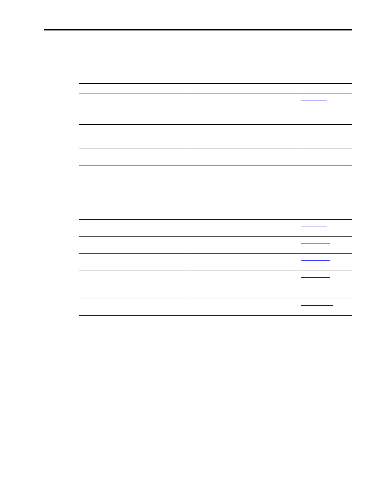
Contents of this Manual
Refer to the following listing for the descriptive contents of this
installation manual.
Chapter Title Contents
Preface Describes the purpose, background, and
scope of this manual. Also specifies the
audience for whom this manual is intended.
1 Installing Your Ultra5000 Provides mounting information for the
Ultra5000.
2 Ultra5000 Connector
Information
3 Connecting Your Ultra5000 Provides steps to follow when applying
4 Commissioning Your
Ultra5000
5 Maintaining Your Ultra5000
Appendix A Specifications and
Dimensions
Appendix B Interconnect Diagrams Provides interconnect diagrams for the
Provides connection and wiring information
for the Ultra5000.
power to the Ultra5000 for the first time.
Powering-up and configuring the Ultra5000
drive.
Provides diagnostic aids that help isolate
problems with a drive.
Provides physical, electrical, environmental,
and functional specifications for the
Ultra5000.
Ultra5000.
Appendix C Catalog Numbers and
Accessories
Appendix D Wiring Three Phase Power
to a Single Phase Ultra5000
Provides catalog numbers and descriptions
of the Ultra5000 and related products.
Discusses star (Y) connection of single
phase Ultra5000 drives to a three phase
power source.
Publication 2098-IN001E-EN-P — April 2002
Page 11
Preface P-3
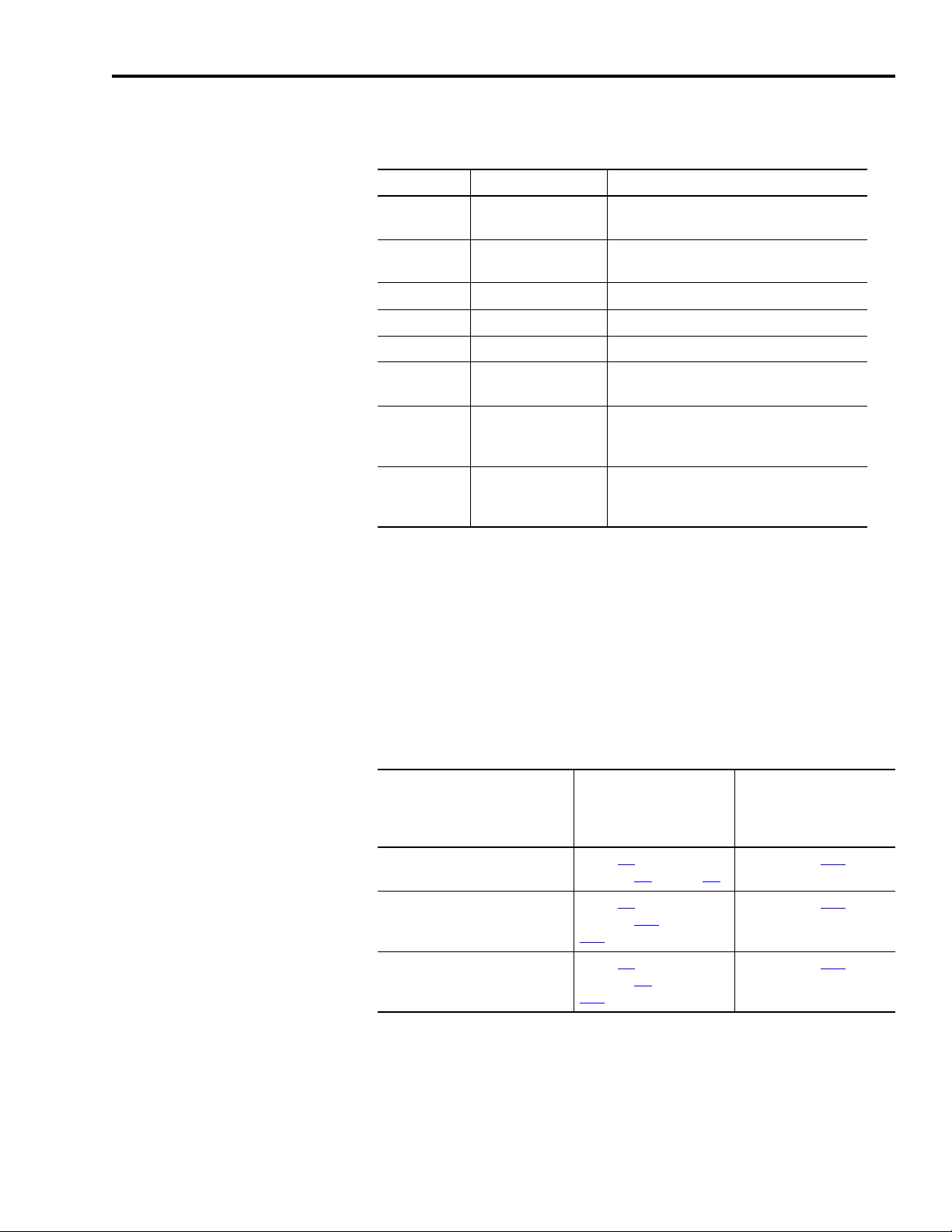
Related Documentation
For: Read This Document: Catalog Number:
Active shunt installation instructions for:
• 2098-IPD-005, -005-DN
• 2098-IPD-010, -010-DN
• 2098-IPD-020, -020-DN
Passive shunt installation instructions for:
• 2098-IPD-075, -075-DN
• 2098-IPD-150, -150-DN
Passive shunt installation instructions for:
• 2098-IPD-030, -030-DN
Passive shunt installation instructions for:
• 2098-IPD-HV030, -HV030-DN
• 2098-IPD-HV050, -HV050-DN
• 2098-IPD-HV100, -HV100-DN
• 2098-IPD-HV150, -HV150-DN
• 2098-IPD-HV220, -HV220-DN
Ultraware™ installation instructions Ultraware CD Installation Instructions 2098-IN002
The following documents contain additional information concerning
related Allen-Bradley products. To obtain a copy, contact your local
Rockwell Automation office or distributor, or access the documents
on-line at
www.theautomationbookstore.com
www.ab.com/manuals/gmc
300 Watt Active Shunt Regulator Installation
Instructions
900 Watt Passive Shunt Module Installation
Instructions
200 Watt Passive Shunt Module Installation
Instructions
2090 Series Passive Shunts Installation
Instructions
.
or
2090-IN001
2090-IN002
2090-IN003
2090-IN004
Information on how to add a DeviceNet™
Expansion Kit to a Ultra5000 drive
Information on programming the Ultra5000 using
the Motion Library
Information on communicating with the
Ultra5000 using DeviceNet
Information on configuring your Ultra5000 using
Ultraware
How to minimize and control system-level noise System Design for Control of Electrical Noise GMC-RM001
Information on attaching Ultra5000 drives to a
DeviceNet network
Ultra5000 DeviceNet Expansion Kit Installation
Instructions
Ultra5000 Motion Library C Programming
Manual
Ultra5000 DeviceNet Reference Manual 2098-RM002
Ultraware User Manual
DeviceNet Cable System Planning and
Installation Manual
2098-IN004
2098-PM001
2098-UM001
DNET-UM072
A copy of the DeviceNet Specification, Volumes I and II, Release 2.0
may be ordered from the web site http://www.odva.org of the Open
Device Vendor Association.
Publication 2098-IN001E-EN-P — April 2002
Page 12

P-4 Preface
Conventions Used in this Manual
Product Receiving and Storage Responsibility
The following conventions are used throughout this manual.
• Bulleted lists such as this one provide information, not procedural
steps.
• Numbered lists provide sequential steps or hierarchical
information.
• Words that you type or select appear in bold.
• When we refer you to another location, the section or chapter
name appears in italics.
You, the customer, are responsible for thoroughly inspecting the
equipment before accepting the shipment from the freight company.
Check the item(s) you receive against your purchase order. If any
items are obviously damaged, it is your responsibility to refuse
delivery until the freight agent has noted the damage on the freight
bill. Should you discover any concealed damage during unpacking,
you are responsible for notifying the freight agent. Leave the shipping
container intact and request that the freight agent make a visual
inspection of the equipment.
Store the product in its shipping container prior to installation. If you
are not going to use the equipment for a period of time, store using
the following guidelines.
• Use a clean, dry location
• Maintain an ambient temperature range of -40 to 70° C
(-40 to 158° F)
• Maintain a relative humidity range of 5% to 95%, non-condensing
• Store it where it cannot be exposed to a corrosive atmosphere
• Store it in a non-construction area
Publication 2098-IN001E-EN-P — April 2002
Page 13

Preface P-5
Allen-Bradley Support
Allen-Bradley offers support services worldwide, with over 75 Sales/
Support Offices, 512 authorized Distributors and 260 authorized
Systems Integrators located throughout the United States alone, plus
Allen-Bradley representatives in every major country in the world.
Local Product Support
Contact your local Allen-Bradley representative for:
• Sales and order support
• Product technical training
• Warranty support
• Support service agreements
Technical Product Assistance
If you need to contact Allen-Bradley for technical assistance, please
review the information in the chapter
call your local Allen-Bradley representative. For the quickest possible
response, please have the catalog numbers of your products available
when you call.
Maintaining Your Ultra5000 first, then
Comments Regarding this Manual
To offer comments regarding the contents of this manual, go to
www.ab.com/manuals/gmc and download the Motion Control
Problem Report form. Mail or fax your comments to the address/fax
number given on the form.
Publication 2098-IN001E-EN-P — April 2002
Page 14

P-6 Preface
Publication 2098-IN001E-EN-P — April 2002
Page 15
Installing Your Ultra5000
ATTENTION
!
Chapter
1
Chapter Objectives
This chapter provides system installation guidelines and procedures
for mounting your Ultra5000. This chapter covers the following topics:
• Complying with European Union Directives
• Before Mounting Your System
Bonding Your System
•
• Mounting Your Ultra5000 Drive
The following information is a guideline for proper
installation. The National Electrical Code and any
other governing regional or local codes overrule this
information. The Allen-Bradley Company cannot
assume responsibility for the compliance or the
noncompliance with any code, national, local or
otherwise, for the proper installation of this system
or associated equipment. If you ignore codes during
installation, the hazard of personal injury and/or
equipment damage exists.
Complying with European Union Directives
If this product is installed within the European Union or EEC regions
and has the CE mark, the following regulations apply.
Note: Declarations of Conformity (DOCs) to EU Directives are
available on-line at www.ab.com/certification for Motion
Control products. The web site is the authoritative source for
verifying compliance and suitability for use of this and other
Rockwell Automation/Allen-Bradley products.
The web site also provides links to other certification agencies
(UL, CSA, etc.).
1 Publication 2098-IN001E-EN-P — April 2002
Page 16

1-2 Installing Your Ultra5000
EMC Directive
This unit is tested to meet Council Directive 89/336/EEC
Electromagnetic Compatibility (EMC) using a technical construction
file and the following standards, in whole or in part:
• EN 50081-2 EMC - Emission Standard, Part 2 - Industrial
Environment
• EN 50082-2 EMC - Immunity Standard, Part 2 - Industrial
Environment
• EN 61800-3 - Adjustable Speed Electrical Power Drive Systems,
Part 3 - EMC Product Standard including specific test methods
The product described in this manual is intended for use in an
industrial environment.
To meet CE requirements, the following additions are required:
• Install a power line filter between the AC power source and the
drive input, as close to the drive as possible. (Refer to
Filters on page C-3.)
AC Line
• Terminate the motor power cable shield to the chassis clamp
provided.
• To meet CE requirements, the following additions may also be
required:
– Run single-phase input wiring in conduit that is grounded to
the enclosure.
– Terminate the shields of the motor power cables and the
motor feedback cables to the enclosure at the point of entry.
Low Voltage Directive
These units are tested to meet Council Directive 73/23/EEC Low
Voltage Directive. The EN 60204-1 Safety of Machinery-Electrical
Equipment of Machines, Part 1-Specification for General Requirements
standard applies in whole or in part. Additionally, the standard
EN 50178 Electronic Equipment for use in Power Installations applies
in whole or in part.
Refer to Appendix
B for interconnect information.
Publication 2098-IN001E-EN-P — April 2002
Page 17

Installing Your Ultra5000 1-3
Before Mounting Your System
Before you mount your Ultra5000 system make sure you understand
the following:
How to Store Your Ultra5000 Before Installation
•
• How to Unpack the System
• Minimum Mounting Requirements
How to Store Your Ultra5000 Before Installation
The Ultra5000 should remain in the shipping container prior to
installation. If the equipment is not to be used for a period of time,
store it as follows:
• Use a clean, dry location
• Maintain an ambient temperature range of -40 to 70° C
(-40 to 158° F)
• Maintain a relative humidity range of 5% to 95%, non-condensing
• Store it where it cannot be exposed to a corrosive atmosphere
• Store it in a non-construction area
Publication 2098-IN001E-EN-P — April 2002
Page 18

1-4 Installing Your Ultra5000
IMPORTANT
How to Unpack the System
Each Ultra5000 ships with the following:
• One Ultra5000 drive
• One installation manual, publication 2098-IN001
• Two I/O connector plugs (28 pin CN1A and 14 pin CN1B)
• One screwdriver
• One clear plastic terminal strip cover
Do not discard the clear plastic terminal strip cover.
Installing the plastic strip on the power terminal strip
provides a physical barrier and protection.
Ultra5000 drives with DeviceNet (2098-IPD-xxx-DN and -HVxxx-DN
only) ship with the following additional items:
• One reference manual, publication 2098-RM002
, for Ultra5000
drives with DeviceNet
• One DeviceNet connector plug for Ultra5000 drives with DeviceNet
Remove all packing material, wedges, and braces from within and
around the components. After unpacking, check the item(s) name
plate catalog number against the purchase order.
Publication 2098-IN001E-EN-P — April 2002
Page 19

Installing Your Ultra5000 1-5
Minimum Mounting Requirements
There are several things that you need to take into account when
preparing to mount the Ultra5000:
• The Ultra5000 is classified as IEC controlgear, and must be housed
in an enclosure that meets IEC60529 requirements for electrical
enclosure of controlgear.
• The ambient temperature of the location in which you will install
the Ultra5000 must not exceed 55° C (131° F).
• You must install the enclosure on a flat, rigid, vertical surface that
will not be subjected to shock, vibration, moisture, oil mist, dust, or
corrosive vapors.
• You need to maintain minimum clearances (refer to Figure 1.1
within the enclosure for proper airflow, easy module access, and
proper cable bend radius.
Refer to Appendix
A for mounting dimensions, power dissipation, and
environmental specifications for the Ultra5000.
)
Publication 2098-IN001E-EN-P — April 2002
Page 20
1-6 Installing Your Ultra5000
50.8 mm (2.0 in.) clearance
for airflow and installation
50.8 mm (2.0 in.) clearance
for airflow and installation
Allow 12.7 mm (0.5 in.)
side clearance
Allow 12.7 mm (0.5 in.)
side clearance
Motor cable entry area for ground
clamp
Minimum cabinet depth = 243.8 mm (9.6 in.)
Minimum front clearance = 76.2 mm (3.0 in.)
IMPORTANT
Ventilation Requirements
This section provides information to assist you in sizing your cabinet
and locating your Ultra5000 drive(s) inside the cabinet.
Figure 1.1
Minimum Clearance Requirements
If the cabinet is ventilated, use filtered or
conditioned air to prevent the accumulation of dust
and dirt on electronic components. The air should be
free of oil, corrosives, or electrically conductive
contaminates.
Refer to Power Dissipation on page A-5 for Ultra5000 power
dissipation specifications.
Publication 2098-IN001E-EN-P — April 2002
Page 21

Installing Your Ultra5000 1-7
IMPORTANT
A
0.38Q
1.8T 1.1–
------------------------=
A
4.08Q
T 1.1–
----------------=
Sizing an Enclosure
As an additional aid in sizing an enclosure, with no active method of
heat dissipation, either of the following approximate equations can be
used:
Metric Standard English
Where T is temperature difference between
inside air and outside ambient (°C), Q is
heat generated in enclosure (Watts), and A
is enclosure surface area (m
surface of all six sides of an enclosure is
calculated as
A = 2dw + 2dh + 2wh A = (2dw + 2dh + 2wh) / 144
Where d (depth), w (width), and h (height)
are in meters.
2
). The exterior
Where T is temperature difference between
inside air and outside ambient (°F), Q is
heat generated in enclosure (Watts), and A
is enclosure surface area (ft²). The exterior
surface of all six sides of an enclosure is
calculated as
Where d (depth), w (width), and h (height)
are in inches.
Transformer Sizing
The Ultra5000 does not require isolation transformers. However, a
transformer may be required to match the voltage requirements of the
controller to the available service. To size a transformer for the main
AC power inputs, the power output (KVA) of each axis must be
known. This can be derived by calculating the horsepower for each
axis and converting that horsepower into units of watts. If you are
supplying power to more than one motor and an Ultra5000, simply
add the kW ratings together from each calculation to get a system kW
total.
If using an autotransformer, ensure that the phase to
neutral/ground voltages do not exceed the input
voltage rating of the drive referenced in General
Power Specifications on Page A-1.
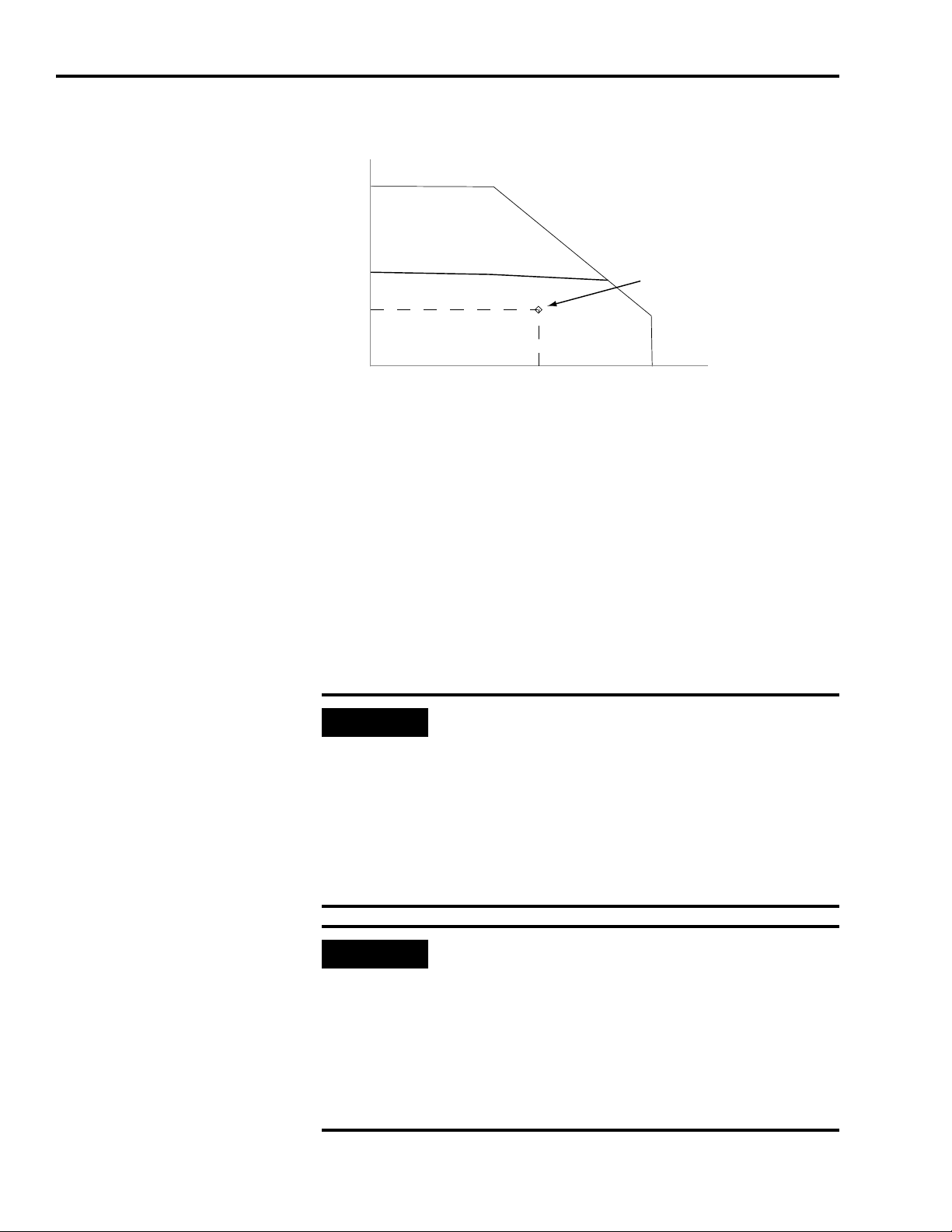
Calculating Transformer Size Based on Speed/Torque Data
Base the transformer size on the operating point within the speed/
torque curve for the drive and motor application as shown in Figure
1.2. The operating point for this hypothetical 230V drive/motor
combination is 23 lb-in and 3200 rpm.
Publication 2098-IN001E-EN-P — April 2002
Page 22
1-8 Installing Your Ultra5000
IMPORTANT
IMPORTANT
TORQUE (lb-in)
3200 rpm SPEED (RPM)
23.0 lb-in
Application
Operating Point
KVA
Speed RPM()Torque lb in–()×
63 025,
--------------------------------------------------------------------------------
746Watts
HP
----------------------- -
×
KVA
1000Watts
-------------------------- -
× 2.0×=
KVA
3200rpm 23.0lb in–×
42 250,
-------------------------------------------------------=
TransformerSize 1.75KVA=
Figure 1.2
Transformer Sizing Based on Speed/Torque Data for Single Phase System
The formula and calculation are:
Definitions:
kW = power or real power
KVA = apparent power
Transformer KVA rating = (Sum of average output power of each axis) x 2.0
.
Calculations are multiplied by a factor to compensate
for the power and loss elements within a power
system.
•A factor of 2.0 is used with a single phase system.
•A factor of 1.5 is used with a three phase system.
This factor minimizes the effects of the secondary
line voltage sagging in the transformer during peak
current periods.
If you are using the Rockwell Automation/
Allen-Bradley system sizing program, the average
speed and average torque data has already been
calculated and can be used in the equation. If you
are not sure of the exact speed and torque in your
application, another approach is to look at the
speed/torque curve for your Ultra5000/motor
combination and use the values for the worst case
continuous speed and torque.
Publication 2098-IN001E-EN-P — April 2002
Page 23

Installing Your Ultra5000 1-9
Fuse Sizing
The Ultra5000 is listed by Underwriters Laboratories, Inc. with fuses
sized as four times the continuous output current of the drives (FLA),
according to UL 508C.
In most cases, fuses selected to match the drive input current rating
will meet the NEC requirements and provide the full drive capabilities.
Dual element, time delay (slow acting) fuses should be used to avoid
nuisance trips during the inrush current of power initialization. Refer
to the section General Power Specifications
current and inrush current specifications.
The Ultra5000 utilizes solid state motor short circuit protection rated as
shown in the table below.
in Appendix A for input
Drive Models:
2098-IPD-xxx-xx Suitable for use on a circuit capable of
2098-IPD-HVxxx-xx Suitable for use on a circuit capable of
Short Circuit Current Rating with No
Fuse Restrictions:
delivering not more than 5000 rms
symmetrical amperes, 240V maximum.
delivering not more than 5000 rms
symmetrical amperes, 480V maximum.
Short Circuit Current Rating with Fuse
Restrictions:
Suitable for use on a circuit capable of
delivering not more than 200,000 rms
symmetrical amperes, 240V maximum,
when protected by high interrupting
capacity, current limiting fuses meeting UL
198C (Class CC, G, J, L, R, T).
Suitable for use on a circuit capable of
delivering not more than 200,000 rms
symmetrical amperes, 480V maximum,
when protected by high interrupting
capacity, current limiting fuses meeting UL
198C (Class CC, G, J, L, R, T).
Mains Input Fuses
Mains input fuses shall be dual element
time delay types class RK5, J or CC only.
Fuse current ratings shall be the following,
or the closest standard value to these
minimums:
2098-IPD-HV030-xx (3kW)
2098-IPD-HV050-xx (5kW)
2098-IPD-HV750-xx (10kW)
2098-IPD-HV100-xx (15kW)
2098-IPD-HV220-xx (22kW)
Auxiliary Input Fuses
Auxiliary input fuses shall be dual element
time delay types class RK5, J or CC only.
Fuse current rating shall be the following, or
the closest standard value to these
minimums.
All drive sizes 0.4 A
5 A
8 A
17 A
25 A
35 A
Publication 2098-IN001E-EN-P — April 2002
Page 24
1-10 Installing Your Ultra5000
Stud-mounting the subpanel
to the enclosure back wall
Stud-mounting a ground bus
or chassis to the subpanel
Subpanel Welded stud
Scrape
Flat washer
If the mounting bracket is coated
with a non-conductive material
(anodized, painted, etc.), scrape
the material around the mounting
hole.
Star washer
Nut
Nut
Flat washer
Mounting bracket or
ground bus
Use a wire brush to remove paint
from threads to maximize ground
connection.
Back wall of
enclosure
Welded
stud
Subpanel
Star washer
Use plated panels or scrape
paint on front of panel.
Subpanel
Nut
Nut
Star washer
Flat washer
Star washer
Star washer
Scrape paint on both sides
of panel and use star
Tapped
Bolt
Flat washer
Ground bus or
mounting bracket
If the mounting bracket is coated
with a non-conductive material
(anodixed, painted, etc.), scrape
the material around the mounting
Bolt-mounting a ground bus or chassis to the back-panel
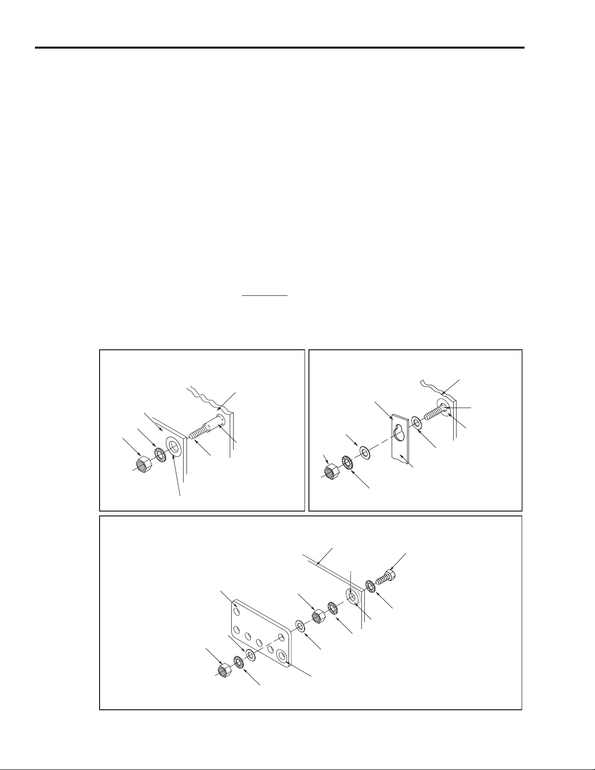
Bonding Your System
Bonding is the practice of connecting metal chassis, assemblies,
frames, shields and enclosures to reduce the effects of electromagnetic
interference (EMI).
Bonding Modules
Unless specified, most paints are not conductive and they act as
insulators. To achieve a good bond between modules and the
subpanel, surfaces need to be paint-free or plated. Bonding metal
surfaces creates a low-impedance exit path for high-frequency energy.
Improper bonding blocks that direct exit path and allows
high-frequency energy to travel elsewhere in the cabinet. Excessive
high-frequency energy can effect the operation of other
microprocessor controlled equipment. The illustrations that follow
(refer to Figure 1.3
for painted panels, enclosures, and mounting brackets.
Figure 1.3
Recommended Bonding Practices
) show details of recommended bonding practices
Publication 2098-IN001E-EN-P — April 2002
Page 25
Installing Your Ultra5000 1-11
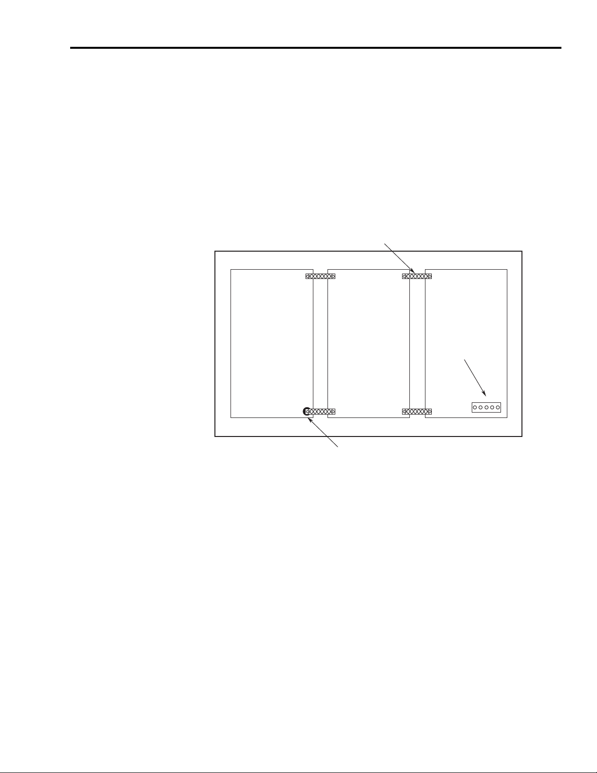
Recommended:
Bond the top and bottom of each subpanel to the cabinet
using 25.4 mm (1.0 in.) by 6.35 mm (0.25 in.) wire braid.
Scrape the paint around each fastener
to maximize metal to metal contact.
Bonded cabinet
ground bus to
subpanel
Recommended:
Bond the top and bottom of each subpanel to the cabinet
using 25.4 mm (1.0 in.) by 6.35 mm (0.25 in.) wire braid.
Scrape the paint around each fastener
to maximize metal to metal contact.
Bonded cabinet
ground bus to
subpanel
Bonding Multiple Subpanels
Bonding multiple subpanels creates a common low impedance exit
path for the high frequency energy inside the cabinet. Subpanels that
are not bonded together may not share a common low impedance
path. This difference in impedance may affect networks and other
devices that span multiple panels. Refer to the figure below for
recommended bonding practices.
Figure 1.4
Multiple Subpanels and Cabinet
Publication 2098-IN001E-EN-P — April 2002
Page 26
1-12 Installing Your Ultra5000
ATTENTION
!
Mounting Your Ultra5000 Drive
The procedures in this section assume you have prepared your panel
and understand how to bond your system. For installation instructions
regarding other equipment and accessories, refer to the instructions
that came with each of the accessories for their specific requirements.
This product contains ESD (Electrostatic Discharge)
sensitive parts and assemblies. Follow static control
precautions when you install, test, service, or repair
this assembly.
Refer to Allen-Bradley publication 8000-4.5.2
Guarding Against Electrostatic Damage or any other
applicable ESD Protection Handbook.
Failure to observe this precaution may result in
damage to the equipment.
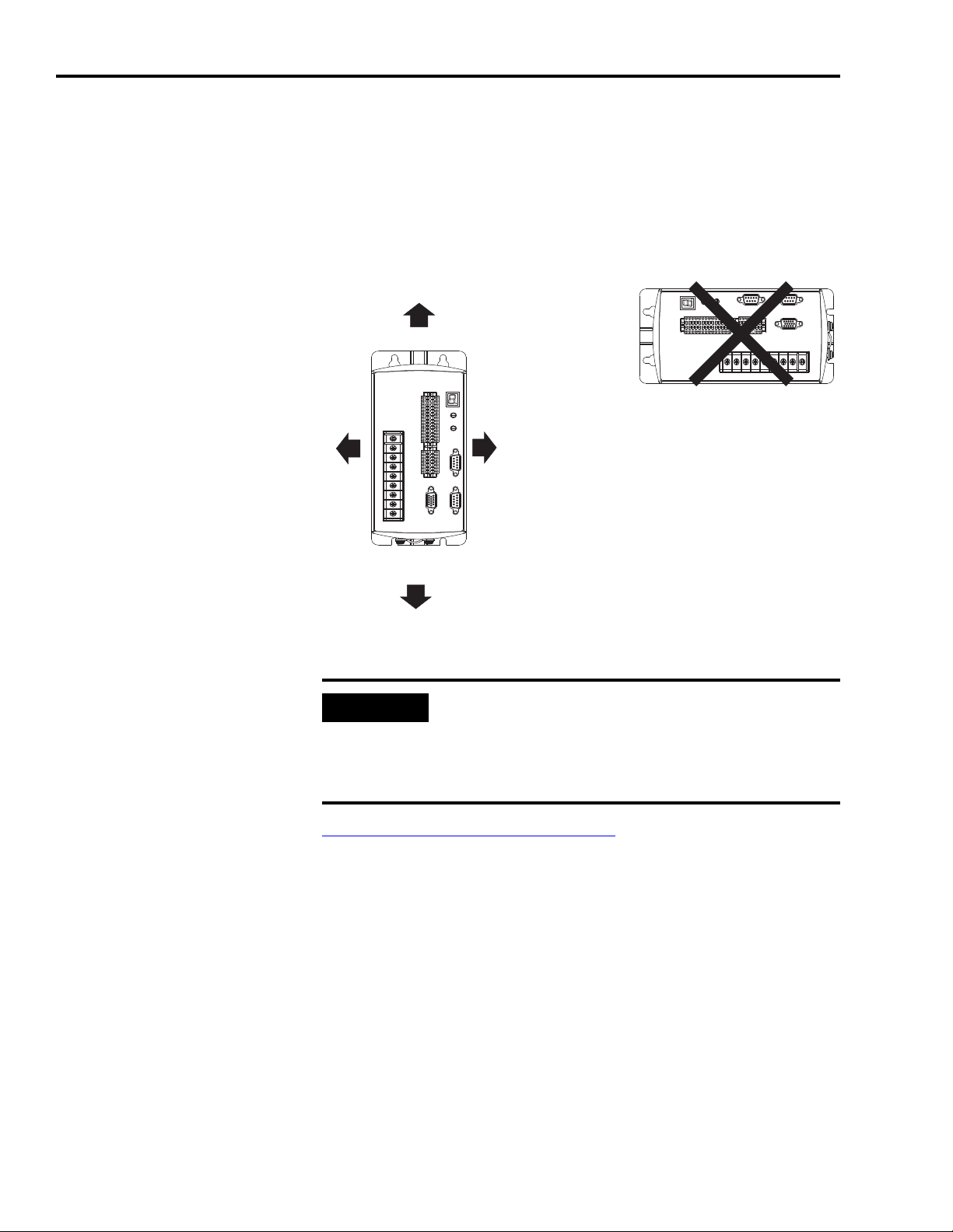
To mount your Ultra5000 drive:
1. Layout the positions for the Ultra5000 and accessories in the
enclosure. Mounting hole dimensions for the Ultra5000 are shown
in Appendix A.
,
2. Attach the Ultra5000 to the cabinet, first using the upper mounting
slots of the drive and then the lower. The recommended mounting
hardware is M5 metric (1/4-20) or #10 MS bolts. Observe bonding
techniques as described in Bonding Your System
2. Tighten all mounting fasteners.
.
Publication 2098-IN001E-EN-P — April 2002
Page 27

Ultra5000 Connector Information
Chapter
2
Chapter Objectives
This chapter provides connector information and procedures for
wiring your Ultra5000 and making cable connections. This chapter
includes:
• Understanding Ultra5000 Controller Functions
• Understanding Ultra5000 Connectors
• Understanding Ultra5000 I/O Specifications
• Understanding Motor Encoder Feedback Specifications
• Understanding Auxiliary Encoder Feedback Specifications
• Understanding the Serial Interface
1 Publication 2098-IN001E-EN-P — April 2002
Page 28
2-2 Ultra5000 Connector Information
InterfaceInterface
InterfaceInterface
InterfaceInterface
InterfaceInterface
InterfaceInterface
InterfaceInterface
InterfaceInterface
InterfaceInterface
InterfaceInterface
Digital InputsDigital Inputs
Digital OutputsDigital Outputs
Auxiliary Encoder InputsAuxiliary Encoder Inputs
Motor Encoder OutputsMotor Encoder Outputs
Motor EncoderMotor Encoder
Analog InputsAnalog Inputs
Analog OutputsAnalog Outputs
Gate ArrayGate Array
QuadQuad
ADCADC
DualDual
DACDAC
QuadQuad
ADCADC
POWER MODULEPOWER MODULE
Bus VoltageBus Voltage
InputInput
CurrentCurrent
InputsInputs
PWMPWM
OutputsOutputs
I/O CARDI/O CARD
512Kx8512Kx8
Low SpeedLow Speed
FlashFlash
MemoryMemory
256Kx32256Kx32
System FlashSystem Flash
MemoryMemory
128Kx32128Kx32
High SpeedHigh Speed
SRAMSRAM
64Kx864Kx8
Non-VolatileNon-Volatile
SRAMSRAM
SerialSerial
InterfaceInterface
7-Segment7-Segment
LEDLED
DisplayDisplay
Rotary DIPRotary DIP
SwitchesSwitches
TMS320C32TMS320C32
DSPDSP
Serial Port 1Serial Port 1
Serial Port 2Serial Port 2
Option Card Port 1Option Card Port 1
Option Card Port 2Option Card Port 2
PROCESSOR CARDPROCESSOR CARD
Understanding Ultra5000 Controller Functions
This section provides a short overview of the Ultra5000.
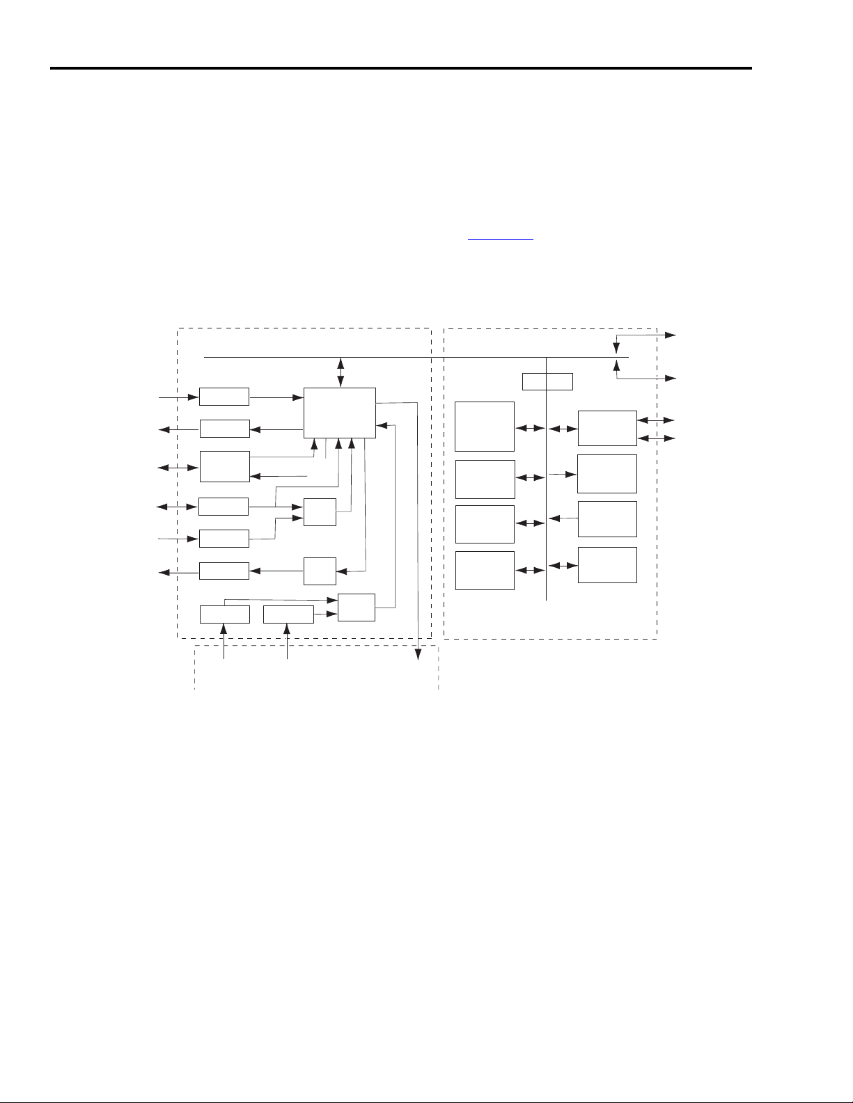
Ultra5000 Block Diagram
The Ultra5000 uses a two-stage circuit card solution with the capability
of adding two additional option cards. The first stage is the processor
circuit board and the second stage handles I/O connections including
a power module interface. Figure 2.1
interfaces.
Figure 2.1
Block Diagram of Ultra5000 Controller Functions
depicts the stages and the
Publication 2098-IN001E-EN-P — April 2002
Page 29
Ultra5000 Connector Information 2-3
Understanding Ultra5000 Connectors
The following table provides a brief description of the Ultra5000 front
panel connectors and describes the connector type.
Designator Description Connector
CN1A User Input/Output 28-pin, 3.5mm, double-row, plugable spring
clamp
CN1B User Input/Output 14-pin, 3.5mm, double-row, plugable spring
clamp
CN2 Motor Feedback 15-pin high-density D-shell
CN3A Main Serial Port 9-pin standard D-shell
CN3B Auxiliary Serial Port 9-pin standard D-shell
TB DC bus, Motor and
AC power
TB1 DC bus, Motor, AC
power, and Auxiliary
AC power
TB2 Shunt 3-position screw style barrier terminal strip
9-position screw style barrier terminal strip
(2098-IPD-005xx, -010-xx, and -020-xx)
11- or 12-position screw style barrier
terminal strip (2098-IPD-030-xx, -075-xx,
-150-xx, and HVxxx-xx)
(2098-IPD-030-xx, -075-xx, -150-xx, and
HVxxx-xx)
CN1A and CN1B signal connections on the Ultra5000 use plugable,
spring-clamp connectors with 3.5mm spacing. Mating connectors for
discrete user wiring are included with your Ultra5000.
CN2, CN3A and CN3B signal connections on the Ultra5000. Mating
connectors for these D-shell type connectors are commonly available.
DeviceNet signal connections on the Ultra5000 with DeviceNet
(2098-IPD-xxx-DN and -HVxxx-DN only) use a 5-pin DeviceNet
connector. The mating connector is included with your Ultra5000.
For connector pin-outs and
the location of connectors,
switches, and status LEDs
on:
2098-IPD-xxx Ultra5000 drives Figure 2.2
2098-IPD-xxx-DN Ultra5000
drives with DeviceNet interface
2098-IPD-HVxxx high voltage
(460VAC) Ultra5000 drives
For I/O, Motor
Feedback and Serial
Communications Port
Connections refer to:
on pages 2-5
Figure 2.5
on pages 2-13
2-15
.
Figure 2.7
on pages 2-5
2-17
.
and the tables
through 2-7.
and the tables
through
and the tables
through
For Terminal Block
(Power) Connections
refer to:
table on page 3-17
table on page 3-17
table on page 3-17
.
.
.
Publication 2098-IN001E-EN-P — April 2002
Page 30
2-4 Ultra5000 Connector Information
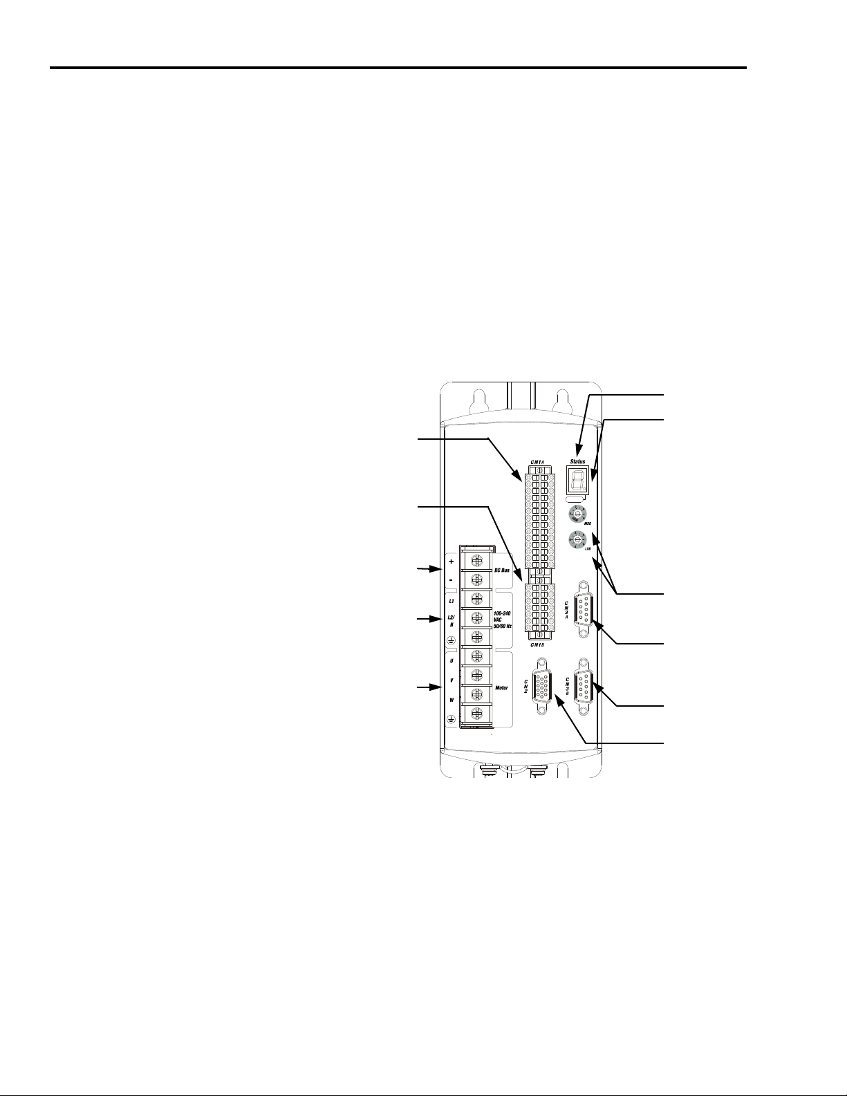
PWR
Seven Segment
Status LED
Logic Power LED
CN3A 9-pin
Main Serial Port
CN2 15-pin
Motor Encoder
CN1A 28-pin
Digital I/O
Node Address
Selector Switche
CN1B 14-pin
Auxiliary Encoder
and Analog I/O
CN3B 9-pin
Auxiliary Serial P
230V Ultra5000 Front Panel Connections
This section describes and provides a visual reference to the drive’s
connectors.
500W, 1 kW, and 2 kW Ultra5000 (2098-IPD-005, -010, and -020)
Use the figure below to locate the front panel connections on the
Ultra5000 230V drives (500W, 1 kW, and 2 kW). Detailed descriptions
of the connections are provided.
Figure 2.2
Ultra5000 Front Panel Connections
for 2098-IPD-005, -010, and -020
Publication 2098-IN001E-EN-P — April 2002
Page 31

Ultra5000 Connector Information 2-5
I/O Connectors
CN1A (28-pin) and CN1B (14-pin) are plugable, double-row, spring
clamp connectors with 3.5mm spacing. Maximum wire gauge for
these connectors is 0.75 mm
The following tables provide the signal description and pin-outs for
the CN1A and CN1B I/O connectors.
Note: These tables are arranged to match the drive’s I/O pin
arrangement..
2
(18 AWG).
CN1A
Pin
15 Digital Input 9 INPUT9 1 Digital Input 1
16 Digital Input 10 INPUT10 2 Digital Input 2
Description Signal CN1A
Pin
Description Signal
2
INPUT1
2
INPUT2
17 Digital Input 11 INPUT11 3 Digital Input 3 INPUT3
18 Digital Input 12 INPUT12 4 Digital Input 4 INPUT4
19 Digital Input 13 INPUT13 5 Digital Input 5 INPUT5
20 Digital Input 14 INPUT14 6 Digital Input 6 INPUT6
21 Digital Input 15 INPUT15 7 Digital Input 7 INPUT7
22 Digital Input 16 INPUT16 8 Digital Input 8 INPUT8
23 Digital Output 5 OUTPUT5 9 Digital Output 1 OUTPUT1
24 Digital Output 6 OUTPUT6 10 Digital Output 2 OUTPUT2
25 Digital Output 7 OUTPUT7 11 Digital Output 3 OUTPUT3
26 Relay Output 1+ OUTPUT8+ 12 Digital Output 4 OUTPUT4
27 Relay Output 1- OUTPUT8- 13 Shield Termination SHIELD
1
28 I/O Ground IOCOM
1
The Ultra5000 0.5, 1.0, and 2.0 kW drives (2098-IPD-005-xx, 2098-IPD-010-xx, 2098-IPD-020-xx, and 2098-IPD-HVxxx-xx
models) require a user supplied I/O power source. Refer to
2
High speed inputs. Refer to Digital Inputs on page 2-20 for additional information.
14 I/O Power Supply IOPWR 1
Digital I/O Power Supply on page 2-19 for more information.
CN1B
Pin
Description Signal CN1B
Pin
Description Signal
8 5V Ground +5VCOM 1 5V Power Supply +5V
9 Analog Input 1 AIN1 2 Auxiliary Encoder I/O A+ AX+
10 Analog Input 2 AIN2 3 Auxiliary Encoder I/O A- AX11 5V Ground +5VCOM 4 Auxiliary Encoder I/O B+ BX+
12 Analog Output 1 AOUT1 5 Auxiliary Encoder I/O B- BX13 Analog Output 2 AOUT2 6 Auxiliary Encoder I/O I+ IX+
14 Shield Termination SHIELD 7 Auxiliary Encoder I/O I- IX-
Publication 2098-IN001E-EN-P — April 2002
Page 32

2-6 Ultra5000 Connector Information
Connector Pinout
Pin 10
Pin 15
Pin 11
Pin 5
Pin 1
Pin 6
Motor Encoder Connector
The following table provides the signal descriptions and pin-outs for
the CN2 motor encoder (15-pin) connector.
CN2 Pin Description Signal
1 Channel A+ AM+
2 Channel A- AM3 Channel B+ BM+
4 Channel B- BM5 Channel I+ IM+
6Common ECOM
7 Reserved
on 2098-005-xx, -010-xx, -020-xx
Encoder Power (+9V)
on 2098-030-xx, -050-xx, -075-xx,
-150-xx, -HV030-xx, -HV050-xx,
-HV100-xx, -HV150-xx, and
-HV220-xx
–
EPWR +9V
8 Commutation Channel S3 S3
9 Positive Overtravel Limit +LIMIT
10 Channel I- IM11 Thermostat TS
12 Commutation Channel S1 S1
13 Commutation Channel S2 S2
14 Encoder Power (+5V) EPWR +5V
15 Negative Overtravel Limit -LIMIT
Publication 2098-IN001E-EN-P — April 2002
Page 33

Ultra5000 Connector Information 2-7
Connector Pinout
Pin 9
Pin 6
Pin 5
Pin 1
Serial Port Connectors
The following table provides the signal descriptions and pin-outs for
the CN3A (Main) and CN3B (Auxiliary) serial port (9-pin) connectors.
Refer to
information.
CN3 Pin Description Signal
1 RS-422/RS-485 Input+ RCV+
2 RS-232 Input RCV
3 RS-232 Output XMT
4 RS-422/RS-485 Output+ XMT+
5Common COM
6Reserved –
7 RS-422/RS-485 Input- RCV8 RS-422/RS-485 Output- XMT-
Default Serial Interface Settings on page 2-34 for additional
9Reserved –
Terminal Block
The following table lists the connections on the Ultra5000 230V drive
(500W, 1 kW, and 2 kW) power terminal block (TB). Refer to
Power Connections on page 3-14 for additional information.
Terminal Block (TB) Locations
(2098-IPD-005xx, -010-xx, -020-xx)
1
DC Bus+
DC BusL1 (Main AC)
L2/N (Main AC)
Safety (Earth) Ground
U (Motor)
V (Motor)
W (Motor)
Motor Case Ground
1
2
2
2
Wiring
1
Do not connect an external I/O power supply to the DC bus. The DC+ and DC- terminals
connect directly to the power bus of the drive.
2
Ensure motor power is wired with proper phasing relative to the motor terminals. On some
motors, the motor leads may be labeled R, S, and T which correspond to U, V, and W.
Publication 2098-IN001E-EN-P — April 2002
Page 34

2-8 Ultra5000 Connector Information
U
V
W
+
-
L1
L2
L1
AUX
L2/N
AUX
Motor
DC Bus
1
2
3
Intern al
Extern al
Shunt
DC Bus
C
N
3
A
C
N
3
B
C
N
2
CN1A
Status
PWR
Node Address
(00-63, PGM)
100-240 VAC
50/60 Hz
AC Input Power Terminals
Motor Power Terminals
DC Bus Terminals for
Shunt Resistor
Seven Segment
Status LED
Logic Power LED
CN3A 9-pin
Main Serial Port
Node Address
Selector Switches
CN3B 9-pin
Auxiliary Serial Port
DC Bus Terminals
CN2 15-pin
Motor Encoder
CN1A 28-pin
Digital I/O
CN1B 14-pin
Auxiliary Encoder
and Analog I/O
3 kW Ultra5000 (2098-IPD-030)
Use the figure below to locate the front panel connections on the
Ultra5000 230V drive (3 kW). Detailed descriptions of the digital
connections are provided on pages 2-5
connections are described below.
Figure 2.3
Ultra5000 Front Panel Connections
for 2098-IPD-030
Status
through 2-7. Power
External
Shunt
Internal
PWR
Node Address
(00-63, PGM)
DC Bus
Motor
DC Bus
100-240 VAC
50/60 Hz
AUX
L2/N
AUX
CN1A
L1
L2
L1
The following tables list the power and shunt connections on the
terminal block (TB). Refer to
Wiring Power Connections on page 3-14
for additional information.
Publication 2098-IN001E-EN-P — April 2002
Page 35

Ultra5000 Connector Information 2-9
Terminal Blocks
The following tables list the connections on the Ultra5000 230V drive
(3 kW) power (TB1) and the shunt (TB2) terminal blocks. Refer
to Wiring Power Connections on page 3-14 for additional information.
Terminal Block 1 (TB1) Locations
(2098-IPD-030-xx)
U (Motor)
V (Motor)
W (Motor)
Motor Case Ground
DC Bus+
DC BusL1 (Main AC)
L2/N (Main AC)
2
2
2
1
1
Safety (Earth) Ground
3
L1 (Aux AC)
L2/N (Aux AC)
1
Do not connect an external I/O power supply to the DC bus. The DC+ and DC- terminals
connect directly to the power bus of the drive.
2
Ensure motor power is wired with proper phasing relative to the motor terminals. On some
motors, the motor leads may be labeled R, S, and T which correspond to U, V, and W.
3 The auxiliary AC power inputs require dual element time delay (slow acting) fuses to
accommodate inrush current. Refer to the section General Power Specifications
A for the inrush current on the auxiliary AC power input.
3
in Appendix
Shunt Terminal Block 2 (TB2) Locations
(2098-IPD-030-xx)
1 - Common Terminal for External or Internal Shunt
1
2 - Internal Shunt Terminal
3 - External Shunt Terminal
1
A jumper, selecting the internal shunt, is factory installed between terminals 1 and 2. Remove the jumper for
applications requiring an external shunt.
Refer to External Shunt Kits on page C-4
1
for information about available external shunt kits.
1
Publication 2098-IN001E-EN-P — April 2002
Page 36

2-10 Ultra5000 Connector Information
U
V
W
+
-
L1L1
L2L2
L1L1
AUXAUX
L2/NL2/N
AUXAUX
MotorMotor
DC BusDC Bus
100-240 VAC100-240 VAC
50/60 Hz50/60 Hz
1
2
3
InternalInternal
ExternalExtern al
ShuntShunt
L3L3
DC BusDC Bus
C
N
3
A
C
N
3
B
C
N
2
CN1ACN1A
CN1BCN1B
TB1TB1
StatusStatus
PWRPWR
Node AddressNode Address
(00-63, PGM)(00-63, PGM)
AC Input Power Terminals
Motor Power Terminals
DC Bus Terminals for
Shunt Resistor
Seven Segment
Status LED
Logic Power LED
CN3A 9-pin
Main Serial Port
Node Address
Selector Switches
CN3B 9-pin
Auxiliary Serial Port
DC Bus Terminals
CN2 15-pin
Motor Encoder
CN1A 28-pin
Digital I/O
CN1B 14-pin
Auxiliary Encoder
and Analog I/O
7.5 kW, and 15 kW Ultra5000 (2098-IPD-075, and -150)
Use the figure below to locate the front panel connections on the
Ultra5000 230V drives (7.5 kW, and 15 kW). Detailed descriptions of
the digital connections are provided on pages 2-5
connections are provided on page 2-11
Figure 2.4
Ultra5000 Front Panel Connections
for 2098-IPD-075, and -150
.
through 2-7. Power
Publication 2098-IN001E-EN-P — April 2002
Page 37

Ultra5000 Connector Information 2-11
I/O Connectors
CN1A (28-pin) and CN1B (14-pin) are plugable, double-row, spring
clamp connectors with 3.5mm spacing. Refer to the tables on page 2-5
for pin-outs.
Motor Encoder Connector
CN2 (15-pin) motor encoder connector is a standard D-shell
connector. Refer to the table on page 2-6
for pin-outs.
Serial Port Connectors
The CN3A (Main) and CN3B (Auxiliary) are standard D-shell
connectors for serial port (9-pin) communications. Refer to the table
on page 2-7
for pin-outs.
Terminal Blocks
The following tables list the connections on the Ultra5000 230V drives
(7.5 kW, and 15 kW) power (TB1) and the shunt (TB2) terminal
blocks. Refer to
additional information.
Wiring Power Connections on page 3-14 for
Publication 2098-IN001E-EN-P — April 2002
Page 38

2-12 Ultra5000 Connector Information
Terminal Block 1 (TB1) Locations
(2098-IPD-075-xx and -150-xx)
U (Motor)
V (Motor)
W (Motor)
2
2
2
Motor Case Ground
1
DC Bus+
DC Bus-
1
L1 (Main AC)
L2 (Main AC)
L3 (Main AC)
Safety (Earth) Ground
3
L1 (Aux AC)
L2/N (Aux AC)
1
Do not connect an external I/O power supply to the DC bus. The DC+ and DC- terminals
connect directly to the power bus of the drive.
2
Ensure motor power is wired with proper phasing relative to the motor terminals. On some
motors, the motor leads may be labeled R, S, and T which correspond to U, V, and W.
3 The auxiliary AC power inputs require dual element time delay (slow acting) fuses to
accommodate inrush current. Refer to the section General Power Specifications
A for the inrush current on the auxiliary AC power input.
3
in Appendix
Shunt Terminal Block 2 (TB2) Locations
(2098-IPD-075-xx and -150-xx)
1 - Common Terminal for External or Internal Shunt
1
2 - Internal Shunt Terminal
3 - External Shunt Terminal
1
A jumper, selecting the internal shunt, is factory installed between terminals 1 and 2. Remove the jumper for
applications requiring an external shunt.
External Shunt Kits on page C-4 for information about available external shunt kits.
Refer to
1
1
Publication 2098-IN001E-EN-P — April 2002
Page 39

Ultra5000 Connector Information 2-13
AUTOBAUD
DeviceNet
PWR
AC Input Power Terminals
Motor Power Terminals
DC Bus Terminals for
Active Shunt Resistor Kit
Seven Segment
Status LED
Logic Power LED
CN3A 9-pin
Main Serial Port
CN2 15-pin
Motor Encoder
CN1A 28-pin
Digital I/O
DeviceNet Interface
Node Address
Selector Switches
Data Rate
Switch
Module Status LED
Network Status LED
CN1B 14-pin
Auxiliary Encoder
and Analog I/O
CN3B 9-pin
Auxiliary Serial Port
230V Ultra5000 with DeviceNet Front Panel Connections
This section describes and provides a visual reference to drive’s
having the DeviceNet interface.
500W, 1 kW, and 2 kW Ultra5000 with DeviceNet (2098-IPD-005-DN, -010-DN, and -020-DN)
Use the figure below to locate the front panel connections on the
230V Ultra5000 with DeviceNet drives (500W, 1 kW, and 2 kW).
Detailed descriptions of the digital connections are provided on pages
through 2-7. Power connections are provided on page 2-11.
2-5
DeviceNet connections are provided on page 2-14
Figure 2.5
Ultra5000 with DeviceNet Front Panel Connections
for 2098-IPD-005-DN, -010-DN, and -020-DN
.
Publication 2098-IN001E-EN-P — April 2002
Page 40

2-14 Ultra5000 Connector Information
I/O Connectors
CN1A (28-pin) and CN1B (14-pin) are plugable, double-row, spring
clamp connectors with 3.5mm spacing. Refer to the tables on page 2-5
for pin-outs.
Motor Encoder Connector
CN2 (15-pin) motor encoder connector is a standard D-shell
connector. Refer to the table on page 2-6
for pin-outs.
Serial Port Connectors
The CN3A (Main) and CN3B (Auxiliary) are standard D-shell
connectors for serial port (9-pin) communications. Refer to the table
on page 2-7
for pin-outs.
DeviceNet Connector
The following table provides the signal descriptions and pin-outs for
the DeviceNet port (5-pin) connector.
Terminal Signal Description
1 V- Network Power Common 24V DC
2 Can_L Network Communication Signal Line
3 Shield Shield
4 Can_H Network Communication Signal Line
5 V+ Network Power 24V DC
Publication 2098-IN001E-EN-P — April 2002
Page 41

Ultra5000 Connector Information 2-15
U
V
W
+
-
L1L1
L2L2
L1L1
AUXAUX
L2/NL2/N
AUXAUX
MotorMotor
DC BusDC Bus
100-240 VAC100-240 VAC
50/60 Hz50/60 Hz
1
2
3
InternalInte rnal
ExternalExte rnal
ShuntSh unt
L3L3
DC BusDC Bus
C
N
3
A
C
N
3
B
C
N
2
CN1ACN1A
CN1BCN1B
TB1TB1
StatusStatus
PWRPWR
Node AddressNode Address
(00-63, PGM)(00-63, PGM)
AUTOBAUDAUTOBAUD
DeviceNetDeviceNet
DeviceNet Interface
Data Rate
Switch
Module Status LED
Network Status LED
AC Input Power Terminals
Motor Power Terminals
DC Bus Terminals for
Shunt Resistor
Seven Segment
Status LED
Logic Power LED
CN3A 9-pin
Main Serial Port
Node Address
Selector Switches
CN3B 9-pin
Auxiliary Serial Port
DC Bus Terminals
CN2 15-pin
Motor Encoder
CN1A 28-pin
Digital I/O
CN1B 14-pin
Auxiliary Encoder
and Analog I/O
ote: 2098-IPD-030-DN
3 kW, 7.5 kW, and 15 kW Ultra5000
(2098-IPD-005-DN, -010-DN, and -020-DN)
Use the figure below to locate the front panel connections on the
230V Ultra5000 with DeviceNet drives (3 kW, 7.5 kW, and 15 kW).
Detailed descriptions of the connections are provided. Detailed
descriptions of the digital connections are provided on pages 2-5
through 2-7
DeviceNet connections are provided on page 2-14
Figure 2.6
Ultra5000 with DeviceNet Front Panel Connections
for 2098-IPD-030-DN, -075-DN, and -150-DN
. Power connections are provided on page 2-11.
.
Publication 2098-IN001E-EN-P — April 2002
Page 42

2-16 Ultra5000 Connector Information
Device
Net
DANGER
DeviceNet Interface
Data Rate
Switch
Module Status LED
Network Status LED
AC Input Power Terminals
Motor Power Terminals
DC Bus Terminals for
Shunt Resistor
Seven Segment
Status LED
Logic Power LED
CN3A 9-pin
Main Serial Port
Node Address
Selector Switches
CN3B 9-pin
Auxiliary Serial Port
DC Bus Terminals
CN2 15-pin
Motor Encoder
CN1A 28-pin
Digital I/O
CN1B 14-pin
Auxiliary Encoder and
Analog I/O
460V Ultra5000 Front Panel Connections
Use the figure below to locate the front panel connections on the
460V Ultra5000 drives (3 kW, 5 kW, 10 kW, 15 kW and 22 kW).
Detailed descriptions of the digital connections are provided on pages
2-5
through 2-7. Power connections are provided on page 2-11.
DeviceNet connections are provided on page 2-14
Figure 2.7
Ultra5000 Front Panel Connections
for 2098-IPD-HV030-xx, -HV050-xx, -HV100-xx, -HV150-xx, and -HV220-xx
.
Device
Net
Publication 2098-IN001E-EN-P — April 2002
Page 43

Ultra5000 Connector Information 2-17
IMPORTANT
I/O Connectors
CN1A (28-pin) and CN1B (14-pin) are plugable, double-row, spring
clamp connectors with 3.5mm spacing. Refer to the tables on page 2-5
for pin-outs.
Motor Encoder Connector
CN2 (15-pin) motor encoder connector is a standard D-shell
connector. Refer to the table on page 2-6
for pin-outs.
Serial Port Connectors
The CN3A (Main) and CN3B (Auxiliary) are standard D-shell
connectors for serial port (9-pin) communications. Refer to the table
on page 2-7
for pin-outs.
Terminal Blocks
The following tables list the connections on the 460V Ultra5000 drives
(3 kW, 5 kW, 10 kW, 15 kW and 22 kW) power (TB1) and the shunt
(TB2) terminal blocks. Refer to
page 3-14 for additional information.
The 2098-IPD-HVxxx-xx drives can be powered with
230-240 Vrms in order to be used in conjunction with
motors designed for 230V operation. In such cases,
the voltage levels used for shunting and DC bus
overvoltage limits are adjusted to be compatible with
the voltage limit of the motor.
Wiring Power Connections on
Publication 2098-IN001E-EN-P — April 2002
Page 44

2-18 Ultra5000 Connector Information
.
Terminal Block 1 (TB1) Locations
(2098-IPD-HVxxx-xx)
DC Bus+
DC BusW (Motor)
V (Motor)
U (Motor)
Ground (
L3 (Main AC)
L2 (Main AC)
L1 (Main AC)
L1 (Aux AC)
L2 (Aux AC)
1
2
3 The auxiliary AC power inputs require dual element time delay (slow acting) fuses to
1
1
2
2
2
Motor and Earth
3
3
Do not connect an external I/O power supply to the DC bus. The DC+ and DC- terminals
connect directly to the power bus of the drive.
Ensure motor power is wired with proper phasing relative to the motor terminals. On some
motors, the motor leads may be labeled R, S, and T which correspond to U, V, and W.
accommodate inrush current. Refer to the section General Power Specifications
A for the inrush current on the auxiliary AC power input.
)
in Appendix
Shunt Terminal Block 2 (TB2) Locations
(2098-IPD-HVxxx-xx)
1 - Common Terminal for External or Internal Shunt
1
2 - Internal Shunt Terminal
3 - External Shunt Terminal
1
A jumper, selecting the internal shunt, is factory installed between terminals 1 and 2. Remove the jumper for
applications requiring an external shunt.
External Shunt Kits on page C-4 for information about available external shunt kits.
Refer to
1
1
Publication 2098-IN001E-EN-P — April 2002
Page 45

Ultra5000 Connector Information 2-19
Understanding Ultra5000 I/O Specifications
A description of the Ultra5000 input/output is provided on the
following pages.
Digital I/O Power Supply
Power for the digital I/O on 0.5 kW, 1.0 kW, and 2.0 kW Ultra5000
230V drives (2098-IPD-005 through -020) and all 460V drives
(2098-IPD-HVxxx-xx) must be provided by an external 12-24V dc
power supply.
Power for the digital I/O on 3.0 kW through 15 kW Ultra5000 drives
(2098-IPD-030 through -150) is provided by an external 12-24V dc
power supply or by a 24V dc power source internal to the drive.
Two jumpers on the regulator board must be repositioned if the
internal power source is to be used. Refer to Figure 3.2
for the location of the jumpers. The internal supply is fused by F1, a
fast acting 1A fuse. The common for the internal supply is lightly
referenced to ground, through a 1M ohm resistor. When using the
internal 24V supply, the common must be grounded during
installation to meet the European Low Voltage Directive.
on Page 3-3
The following table provides a description of the requirements for an
external digital I/O power supply for all Ultra5000 drives
(2098-IPD-005-xx through 2098-IPD-150-xx, and 2098-IPD-HV030-xx
through 2098-IPD-HV220-xx).
Parameter Description Minimum Maximum
I/O Power Supply
Voltage
I/O Power Supply
Current
Voltage range of the external power supply
for proper operation of the digital I/O.
Current draw from the external power
supply for the digital I/O, not including the
relay output usage.
10.8V 26.4V
— 300 mA
The following table provides specifications on the internal digital I/O
power supply for the 230V Ultra5000 3.0 kW through 15 kW drives
(2098-IPD-030 through -150 only).
Parameter Description Minimum Maximum
Output Voltage Voltage difference between I/O PWR and
I/O COM
Output Current Current flow — 300 mA
21.6V 28.0V
Publication 2098-IN001E-EN-P — April 2002
Page 46

2-20 Ultra5000 Connector Information
IMPORTANT
Digital Inputs
There are sixteen general purpose digital inputs. They are not
connected in hardware to perform a particular function. All digital
inputs have the same hardware configuration, shown in Figure 2.8
Configure your digital inputs, in a group, as active
high (current sinking) or active low (current
sourcing).
Inputs 1 and 2 use high-speed circuitry, with minimal propagation
delays, suitable for use in registration applications. Any input can be
assigned through firmware to latch the motor or auxiliary position in
hardware.
Figure 2.8
Digital Input Circuit
.
Publication 2098-IN001E-EN-P — April 2002
The following table provides a description of the digital input
specifications.
Parameter Description Minimum Maximum
ON State Voltage,
Active High
Configuration
ON State Voltage,
Active Low
Configuration
ON State Current Current flow to guarantee an ON State 3.0 mA 12.0 mA
OFF State Voltage,
Active High
Configuration
Voltage applied to the input, with
respect to IOCOM, to guarantee an ON
state.
Voltage applied to the input, with
respect to IOPWR, to guarantee an ON
state.
Voltage applied to the input, with
respect to IOCOM, to guarantee an OFF
state.
10.8V 26.4V
-26.4V -10.8V
-1.0V 3.0V
Page 47

Ultra5000 Connector Information 2-21
Parameter Description (Continued) Minimum Maximum
OFF State Voltage,
Active Low
Configuration
Propagation
Delay,
High Speed Inputs
Propagation
Delay,
Low Speed Inputs
Voltage applied to the input, with
respect to IOPWR, to guarantee an OFF
state.
Signal propagation delay from the high
speed digital input to the firmware
accessible registers, active high or
active low, turning ON or turning OFF.
Signal propagation delay from the low
speed digital input to the
firmware-accessible registers, active
high or active low, turning ON or turning
OFF.
-3.0V 1.0V
— 0.5 mS
— 100 mS
Publication 2098-IN001E-EN-P — April 2002
Page 48

2-22 Ultra5000 Connector Information
IMPORTANT
Digital Outputs
There are eight general purpose digital outputs. They are not
connected in hardware to perform a particular function. Seven digital
outputs are transistor outputs, and the drive has a single relay output
(Output 8) with normally open contacts.
The configuration of the transistor outputs is shown in Figure 2.9
the configuration of the relay output is shown in Figure 2.10
.
There is no overload protection on the transistor
outputs. To some degree, the bipolar transistors limit
their own current output, but they have not been
designed to specifically protect against shorts to
power or ground.
Figure 2.9
Transistor Output Hardware Configuration
, and
Publication 2098-IN001E-EN-P — April 2002
The following table provides a description of the transistor digital
output specifications.
Parameter Description Minimum Maximum
ON State
Current
OFF State
Current
ON State
Voltage
OFF State
Voltage
Current flow when the output transistor is ON — 50 mA
Current flow when the output transistor is OFF — 0.1 mA
Voltage across the output transistor when ON — 1.5V
Voltage across the output transistor when OFF — 50V
Page 49

Ultra5000 Connector Information 2-23
CN1A-26
Relay +
CN1A-27
Relay -
Normally
Open
Relay
AIN
1kW
1000pF
10kW
Figure 2.10
Relay Output Hardware Configuration
The following table provides a description of the relay output
specifications.
Parameter Description Minimum Maximum
ON State
Current
Current flow when the relay is closed — 1A
ON State
Contact resistance when the relay is closed — 1W
Resistance
OFF State
Voltage
OFF State
Voltage across the contacts when the relay is
— 30V
open
Current flow when the relay is open — 0.01 mA
Current
Analog Inputs
There are two single-ended general purpose analog inputs to use as
needed. A 12 bit A/D converter digitizes the signal. The configuration
of the input is shown in Figure 2.11
Figure 2.11
Analog Input Configuration
.
The following table provides a description of the analog COMMAND
input specifications.
Parameter Description Minimum Maximum
Resolution Number of states that the input signal is divided
into which is 2(to the number of bits).
Input
Impedance
Input Signal
Range
Open circuit impedance measured between the
+ and - inputs.
Voltage applied to the input - Usable -10V +10V
Voltage applied to the input - Limit -14V +14V
Publication 2098-IN001E-EN-P — April 2002
12 bits —
10 kW —
Page 50

2-24 Ultra5000 Connector Information
IMPORTANT
1kΩ
1000pF
AOUT
Parameter Description Minimum Maximum
Offset Error Deviation from the correct value expected from
analog-to-digital conversion when 0V is applied
to the input.
Gain Error Deviation of the transfer function from unity
gain, expressed in a percent of full scale.
— 50 mV
—1%
Propagation
Delay
Delay from the input to the firmware-accessible
registers.
— 100 mS
Analog Outputs
There are two analog outputs to use as needed. A 12 bit D/A
converter generates an analog representation of the digital command
value. The analog outputs are set to zero after the power comes up.
Figure 2.12
Figure 2.12
Analog Output Configuration
shows the configuration of the analog outputs.
Output values can vary during power-up until the
specified power supply voltage is reached.
Publication 2098-IN001E-EN-P — April 2002
The following table provides a description of the analog output
specifications.
Parameter Description Minimum Maximum
Resolution Number of states that the output signal is
divided into, which is 2(to the number of bits).
Output
Current
Output
Signal
Range
Offset Error Deviation when the output should be at 0V. — 50 mV
Gain Error Deviation of the transfer function from unity
Current capability of the output. -2 mA +2 mA
Range of the output voltage. -10V +10V
gain, expressed in a percent of full scale.
12 Bits —
—1%
Page 51

Ultra5000 Connector Information 2-25
AM and BM Channel Inputs
IM Channel Input
Understanding Motor Encoder Feedback Specifications
The Ultra5000 can accept motor encoder signals from the following
types of encoders:
• Incremental encoders with TTL outputs, with or without Hall
signals
• Sine/Cosine encoders, with or without Hall signals
• Intelligent absolute encoders
• Intelligent high-resolution encoders
• Intelligent incremental encoders
Note: The intelligent absolute, high-resolution, and incremental
encoders are available only in Allen-Bradley motors.
AM, BM, and IM Inputs
AM, BM, and IM Input encoder signals are filtered using analog and
digital filtering. The inputs also include illegal state change detection.
Refer to Figure 2.13
for a schematic of the AM, BM, and IM inputs.
Figure 2.13
Schematic of the Motor Encoder Inputs
+5 V
+
1k W
-
1k W
1k W
1k W
1k W
56 pF
56 pF
56 pF
56 pF
1k W
1k W
100 pF
100 pF
10k W
10k W
10k W
1k W
+
56 pF
1k W
56 pF
10k W
Publication 2098-IN001E-EN-P — April 2002
Page 52

2-26 Ultra5000 Connector Information
The Ultra5000 supports both TTL and Sine/Cosine encoders. The
following table provides a description of the AM, BM, and IM inputs
for TTL encoders.
Parameter Description Minimum Maximum
AM, BM, and IM
ON State
Input Voltage
AM, BM, and IM
OFF State
Input Voltage
Common Mode
Input Voltage
DC Current Draw Current draw into the + or - input. -30 mA 30 mA
AM, BM Input
Signal Frequency
Input voltage difference between the +
input and the - input that is detected as
an ON state.
Input voltage difference between the +
input and the - input that is detected as
an OFF state.
Potential difference between any
encoder signal and logic ground.
Frequency of the AM or BM signal
inputs. The count frequency is 4 times
this frequency, since the circuitry counts
all four transitions.
+1.0V +12.0V
-1.0V -12.0V
-7.0V +12.0V
— 2.5 MHz
IM Pulse Width Pulse width of the index input signal.
Since the index is active for a
percentage of a revolution, the speed
will determine the pulse width.
AM / BM
Phase Error,
2.5 MHz Line
Frequency
AM / BM
Phase Error,
1 MHz Line
Frequency
Amount that the phase relationship
between the AM and BM inputs can
deviate from the nominal 90°.
Amount that the phase relationship
between the AM and BM inputs can
deviate from the nominal 90°.
125 nS —
-22.5° +22.5°
-45° +45°
The following table provides a description of the AM and BM inputs
for Sine/Cosine encoders.
Parameter Description Minimum Maximum
AM and BM
Input Signal
Frequency
AM and BM
Input Voltage
Frequency of the AM or BM signal inputs. — 100 kHz
Peak-to-peak input voltages of the AM and BM
inputs
0.5V (p-p) 2.0V (p-p)
Publication 2098-IN001E-EN-P — April 2002
Page 53

Ultra5000 Connector Information 2-27
1k Ω
1k Ω
+ 5 V
+ 5 V
0.01
µ
F
COMMON COMMON
TS
Hall Inputs
The Ultra5000 uses Hall Signals to initialize the commutation angle for
sinusoidal commutation. Hall Signals must be single-ended and can be
either open collector type or TTL type. Figure 2.14
configuration of the Hall inputs. If the motor does not have Hall
signals, the drive can configured through software to omit the Hall
signal requirement.
Figure 2.14
Hall Input Configuration
+ 5 V
1k Ω
S1, S2, or S3
1k Ω
µ
F
56
shows the
+ 5 V
COMMON COMMON
Thermostat Input
The Ultra5000 can monitor a thermostat signal from a motor and will
generate a fault if the motor overheats. Figure 2.15
configuration of the thermostat input. Figure 2.16
a typical connection to a motor with a normally closed thermostat.
The logic is designed so that an open condition will generate a fault. If
the motor does not have a thermostat signal, the drive can be
configured through software to ignore the signal.
Figure 2.15
Thermostat Input Configuration
shows the
on page 2-28 shows
Publication 2098-IN001E-EN-P — April 2002
Page 54

2-28 Ultra5000 Connector Information
TS
ECOM
Thermostat
normally
closed
Drive
Motor/Encoder
1k Ω
1k Ω
+ 5 V
+ 5 V
0.01 µF
COMMON COMMON
+ Limit
or
- Limit
Motor/Encoder Ultra5000 Drive
Figure 2.16
Typical Thermostat Connection
+ Limit and - Limit Inputs
The Ultra5000 drive includes overtravel limit inputs on the motor
encoder connector that can be programmed to halt motion. The logic
is designed so that an open condition will halt motion in the
corresponding direction. If these signals are not used, the drive can be
configured through software to ignore the inputs. Figure 2.17
the configuration of the +Limit and -Limit inputs. Figure 2.18
typical connection to a motor with integral limit switches.
shows
shows a
Figure 2.17
+ Limit and - Limit Input Configuration
Figure 2.18
Typical + Limit and - Limit Connection
Positive
Overtravel
Negative
Overtravel
Limit +
Limit -
Publication 2098-IN001E-EN-P — April 2002
Page 55

Ultra5000 Connector Information 2-29
Encoder Phasing
For proper motor commutation and control, it is important that the
motor feedback signals are phased properly. The drive has been
designed so that a positive current applied to a motor will produce a
positive velocity and increasing position readings, as interpreted by
the drive. Additionally, Hall signals are used to initialize the
commutation angle, so the Hall signals must sequence properly and
the phase relationship to the motor back-EMF signals must be
understood. Figure 2.19
signals when positive current is applied to the motor. If the Hall
signals are out of phase with the back-EMF signals, the drive can be
configured through software to compensate for the phase offset, as
long as the sequencing of the Hall signals is correct. Figure 2.20
an example where the Hall signals have an offset of 60 degrees.
Figure 2.19
Sequencing and Phasing of the Hall Signals
shows the proper sequencing of the Hall
shows
Figure 2.20
Sequencing and Phasing of the Hall Signals (60° Hall Offset Example)
Publication 2098-IN001E-EN-P — April 2002
Page 56

2-30 Ultra5000 Connector Information
IMPORTANT
Figure 2.21 shows the proper phasing of TTL A/B encoder signals
when positive current is applied.
Figure 2.21
Phasing of TTL A/B Encoder Signals
A
B
Figure 2.22 shows the proper phasing of Sine/Cosine encoder signals
when positive current is applied.
Notice that the Sine/Cosine encoder signals phasing
is different than the phasing of the TTL encoders.
Figure 2.22
Phasing of Sine/Cosine Encoder Signals
A
B
Publication 2098-IN001E-EN-P — April 2002
Page 57

Ultra5000 Connector Information 2-31
IMPORTANT
A+ or SIN+
A- or SINB+ or COS+
B- or COSI+ or Data+
I- or DataPOWER (+5V)
GROUND
TS+
TSS1
S2
S3
AM+
AM-
BM+
BM-
IM+
IM-
EPWR_5V
ECOM
TS
S1
S2
S3
1
2
3
4
5
10
14
6
11
12
13
8
Drive
Encoder
Drain
Denotes Twisted Pair. Connector Backshell Shielded 360 (both ends).
Motor Encoder Connection Diagram
Figure 2.23 shows a typical wiring diagram of a motor feedback cable.
If the thermostat or limit signals are not available, no connections are
required, but the drive must be configured through software to ignore
these signals. Refer to Appendix B for specific Ultra5000 drive/motor
interconnect diagrams.
Total resistance of the wiring for encoder power and
ground connections between the drive and motor
must be less than 1.4 ohms.
Figure 2.23
Drive/Motor Wiring Diagram
Unbuffered Motor Encoder Outputs
The Ultra5000 passes the motor encoder signals directly to the CN1B
Auxiliary Encoder Output connector without any conditioning.
Buffered Motor Encoder Outputs
The Ultra5000 includes buffered motor encoder outputs. These signals
are generated by the drive after filtering and processing the actual
feedback from the motor. Programmable division is also available.
The buffered motor encoder outputs use RS-485 differential drivers
and have a maximum signal frequency of 2.5 MHz. The drivers can
drive a 2V differential voltage into a 100 ohm load.
Publication 2098-IN001E-EN-P — April 2002
Page 58

2-32 Ultra5000 Connector Information
A
B
+
+5V
+
-
5kW?
1kW?
56pF
-
10kW?
1kW?
56pF
+5V
+5V
10kW?
OUT
IN
OUTPUT ENABLE
Understanding Auxiliary Encoder Feedback Specifications
The Ultra5000 can accept an auxiliary encoder signal of the following
type.
Figure 2.24
Auxiliary Encoder Input Signal Types
Auxiliary Encoder Interface
All encoder input signals (CN1B) are filtered using analog and digital
filtering, including illegal state change detection.
The input circuitry includes pull-up and pull-down resistors for
compatibility with single-ended and open collector signals, in addition
to differential signals.
Figure 2.25
channel. The BX and IX channels have the same configuration.
shows the configuration of the AX Auxiliary Encoder Input
Figure 2.25
Schematic of the Auxiliary Encoder Circuitry
Publication 2098-IN001E-EN-P — April 2002
Page 59

Ultra5000 Connector Information 2-33
The following table provides a description of the auxiliary encoder
interface.
Parameter Description Minimum Maximum
ON State
Input Voltage
OFF State
Input Voltage
Common Mode
Input Voltage
DC Current Draw Current draw into the + and - input. -5mA 5mA
Signal Frequency Frequency of the AX or BX signal inputs.
IX Pulse Width,
A/B/I Mode
AX / BX Phase
Error, 2.5 MHz Line
Frequency, A/B/I
Mode
AX / BX Phase
Error, 1 MHz Line
Frequency, A/B/I
Mode
Input voltage difference between the +
input and the - input that is detected as
an ON state.
Input voltage difference between the +
input and the - input that is detected as
an OFF state.
Potential difference between an encoder
signal and logic ground.
Count frequency is 4 times this
frequency for A/B/I type inputs.
Pulse width of the index input signal.
Since the index is active for a
percentage of a revolution, the speed
will determine the pulse width.
Amount that the phase relationship
between the AM and BM inputs can
deviate from the nominal 90°.
Amount that the phase relationship
between the AM and BM inputs can
deviate from the nominal 90°.
+1.0V +7.0V
-1.0V -7.0V
-7.0V +12.0V
— 2.5 MHz
125 nS —
-22.5° +22.5°
-45° +45°
Publication 2098-IN001E-EN-P — April 2002
Page 60

2-34 Ultra5000 Connector Information
RS-232
RS-485
XMT
RCV
XMTXMT+
RCV+
RCV-
RECEIVE
TRANSMIT
Understanding the Serial Interface
The Ultra5000 provides two physically identical serial ports (Main
Serial Port CN3A and Auxiliary Serial Port CN3B) that implement the
standard NRZ asynchronous serial format, and supports RS-232,
RS-422, and RS-485 communication standards. However, functionality
differs between the ports:
• The CN3A serial port communicates at a data rate fixed by the
drive at 38400 baud. It is primarily for communications between a
PC running Ultraware and the drive.
• The CN3B serial port’s data rate is programmable via the drive’s
user (motion) program. It is primarily for communications between
the drive and other devices requiring an interface to the user
program.
Standard baud rates include 1,200, 2,400, 4,800, 9,600, 19,200, and
38,400 baud. Data lengths of 7 and 8 bits are supported.
The connector pinout dedicates separate pins for the RS-232 and
RS-422/ RS-485 signals, so that the communication standard can be
changed by just using a different cable. Refer to Figure 2.26
for the
serial interface configuration.
Figure 2.26
Serial Interface Configuration
Publication 2098-IN001E-EN-P — April 2002
Default Serial Interface Settings
The default setting of the Ultra5000 serial interface is as follows:
Parameter Default Setting
Baud Rate 38,400
Frame Format 8 Data, No Parity, One Stop
Page 61

Connecting Your Ultra5000
Chapter
3
Chapter Objectives
Powering the Digital I/O
This chapter provides you with information for wiring your Ultra5000.
This chapter includes these sections:
• Powering the Digital I/O
• Understanding Basic Wiring Requirements
• Grounding Your Ultra5000
• Wiring Your Ultra5000
Before you begin these procedures, be sure to read and understand
the information in the previous chapters of this manual.
Note: The procedures in this chapter do not include information
regarding integration with other products.
Depending on the model of the Ultra5000 drive, digital I/O power
may be provided by the 24V dc power supply internal to the drive or
by an external 12-24V power supply.
• A 2098-IPD-005 through -020 230V Ultra5000 drive and any 460V
Ultra5000 drive (2098-IPD-HV030-xx through -HV220-xx) requires
an external 12-24V power supply for proper operation of the
digital I/O.
• A 2098-IPD-030 through -150 Ultra5000 drive’s digital I/O is
powered with an external 12-24V dc power supply, or by a 24V dc
power source internal to the drive.
Requirements for an external digital I/O power supply are:
Parameter Description Minimum Maximum
I/O Power Supply
Voltage
I/O Power Supply
Current
To convert a 230V Ultra5000 drive (2098-IPD-030 through -150) from
the factory set external I/O power supply, a pair of jumpers on the
regulator board must be repositioned. The following section describes
how to access that board and change the location of the two jumpers.
1 Publication 2098-IN001E-EN-P — April 2002
Voltage range of the external power supply
for proper operation of the digital I/O.
Current draw from the external power
supply for the digital I/O, not including the
relay output usage.
10.8V 26.4V
— 300 mA
Page 62

3-2 Connecting Your Ultra5000
ATTENTION
!
ATTENTION
!
Specifications on the internal digital I/O power supply are:
Parameter Description Minimum Maximum
Output Voltage Voltage difference between I/O PWR and
I/O COM
Output Current Current flow — 300 mA
21.6V 28.0V
Accessing the Internal Digital I/O Power Supply
The 230V (2098-IPD-030 through -150) Ultra5000 drives can power the
digital I/O from a 24V dc power source internal to the drive. Perform
the following steps to change the digital I/O power source to the
internal 24V dc power.
DC bus capacitors may retain hazardous voltages
after input power has been removed, but will
normally discharge in several seconds.
Before working on the drive, measure the DC bus
voltage to verify it has reached a safe level or wait a
full 5 minutes to ensure that all voltages on the
system bus have discharged.
Failure to observe this precaution could result in
severe bodily injury or loss of life.
The Ultra5000 contains ESD (Electrostatic Discharge)
sensitive parts.
To avoid damaging these parts, follow static control
precautions when installing, testing, servicing, or
repairing this assembly.
Refer to Allen-Bradley publication 800-4.5.2
Guarding Against Electrostatic Discharge or other
appropriate handbooks on ESD protection.
1. Detach the right cover panel by removing the 3 screws (6-32 x
1/4) in the rear of the drive that secure the cover to the drive. Lift
the rear of the cover and slide it forward until the connectors on
the front of the drive are cleared. Then lift the cover off the drive.
Figure 3.2
connectors.
on page 3-3 shows the location of the screws and
,
Publication 2098-IN001E-EN-P — April 2002
Note: This step assumes the I/O port (CN1A and CN1B) mating
connectors were previously removed.
Page 63

Connecting Your Ultra5000 3-3
Mating
Connectors
6-32 x 1/4” Screws
J12 and J13 position for
EXT 24V dc (factory setting)
U99
U102
Y2
U82
U87U90 U91 U92
U96
U98
U39
U42
U56
U19
RP204
S1 S2
SPARE
RP63
RP77
RP78
RP80
R200
R207
RP6
RP11 RP12
RP15
R131
R136
L24
R43
J11
J12J13
J20 J21
J4A
L3
L6
L13
L14
L16
C191
C200
CN4
D1
E1
F1
J2
J6
C134
C152
C153
C110
C113
C49
C50
C50B
INT
EXT
X1
U84
U30
J12 and J13 position for
INT 24V dc (optional setting)
Fuse (F1) for INT 24V dc circuit.
2. Relocate the digital I/O power jumpers on the regulator board.
Figure 3.2
shows the location of the J12 and J13 jumpers. Move
both jumpers from the EXT position to the INT position.
Note: The fuse (F1) protects the circuit only when the internal
power is selected.
3. Reinstall the cover.
Figure 3.1
Removal of Cover Panel from Ultra5000 Drive
Figure 3.2
Jumper Settings for External or Internal Digital I/O Power
Publication 2098-IN001E-EN-P — April 2002
Page 64

3-4 Connecting Your Ultra5000
ATTENTION
!
IMPORTANT
IMPORTANT
Understanding Basic Wiring Requirements
This section contains basic wiring information for the Ultra5000.
Plan the installation of your system so that you can
perform all cutting, drilling, tapping, and welding
with the system removed from the enclosure.
The system is of an open type construction and care
must be taken to prevent metal debris from falling
into it.
Damage to the equipment could result if metal debris
or other foreign matter contacts or lodges in the
circuitry.
This section contains common PWM servo system
wiring configurations, size, and practices that can be
used in a majority of applications. National Electrical
Code, local electrical codes, special operating
temperatures, duty cycles, or system configurations
take precedence over the values and methods
provided.
Building Your Own Cables
When building your own cables, follow the guidelines listed below.
• Connect the cable shield to the connector shells on both ends of the
cable for a complete 360° connection.
• Use a twisted pair cable whenever possible, twisting differential
signals with each other, and single-ended signals with the
appropriate ground return.
Refer to Appendix C for mating connector kit catalog numbers.
Factory made cables are recommended over
hand-built cables and are designed to minimize EMI.
Publication 2098-IN001E-EN-P — April 2002
Page 65

Connecting Your Ultra5000 3-5
PWR
PWR
PWR
PWR
Maximize distance between high and low
voltage cables on parallel runs
Do not run low
and high
voltage wires
in the same
wireway
120/240V
AC power
Low voltage
communications
control I/O wiring
motor feedback
cables
Always cross
high and low
voltage
conductors at
90° angles
Always separate all low voltage signal
wiring from high voltage power wiring to
reduce affects of EMI and RFI.
Unshielded
conductors
Minimize unshielded
lead length
Motor power
cables
Routing High and Low Voltage Cables
Be aware that when you connect and route power and signal wiring
on a machine or system, radiated noise from nearby relays (relay coils
should have surge suppressors), transformers, and other electronic
drives, can be induced into motor or encoder feedback,
communications, or other sensitive low voltage signals. This can cause
system faults and communication problems. To minimize the levels of
radiated noise, route machine power and signal lines separately.
Figure 3.3
Routing Power and Signal Cables Inside Your Cabinet
Publication 2098-IN001E-EN-P — April 2002
Page 66

3-6 Connecting Your Ultra5000
ATTENTION
!
PWR
PWR
PWR
PWR
Bonded ground bar
(optional)
Safety ground
(terminal 5)
Bonded cabinet ground bus
All ground wiring must
comply with local codes
Ground grid or
power distribution
ground
Always follow
NEC and
applicable local
codes
Ultra5000 Intelligent
Positioning Drives
Grounding Your Ultra5000
We recommend that all equipment and components of a machine or
process system have a common earth ground point connected to their
chassis. A grounded system provides a safety ground path for short
circuit protection. Grounding your modules and panels minimize
shock hazard to personnel and damage to equipment caused by short
circuits, transient overvoltages, and accidental connection of
energized conductors to the equipment chassis. For CE grounding
requirements, refer to Appendix B.
Grounding Your System to the Subpanel
The National Electrical Code contains grounding
requirements, conventions, and definitions. Follow
all applicable local codes and regulations to safely
ground your system. Refer to the illustration below
for details on grounding your Ultra5000. Refer to
Appendix B for the power wiring diagram for your
Ultra5000 drive.
Figure 3.4
Safety Ground Configuration with Multiple Ultra5000 Systems on One Panel
Publication 2098-IN001E-EN-P — April 2002
Page 67

Connecting Your Ultra5000 3-7
Always follow NEC and
applicable local codes
Ground grid or
power distribution
ground
ATTENTION
!
Grounding Multiple Subpanels
To ground multiple subpanels, refer to the figure below.
Figure 3.5
Subpanels Connected to a Single Ground Point
Motor Power Cable Shield Termination
Factory supplied motor power cables for F-Series, H-Series, MP-Series,
N-Series, and W-Series motors are shielded, and the power cable is
designed to be terminated at the drive during installation. A small
portion of the cable jacket is removed which exposes the shield braid.
The exposed area must be clamped to the bottom of the drive chassis
(refer to Figure 3.6
) using the clamp provided.
High voltage can be present on the shield of a power
cable if the shield is not grounded.
To avoid hazard of electrical shock, ensure shielded
power cables are grounded at a minimum of one
point for safety.
Failure to observe these safety procedures could
result in personal injury or equipment damage.
Publication 2098-IN001E-EN-P — April 2002
Page 68

3-8 Connecting Your Ultra5000
V
W
Ultra5000
Motor cable jacket
Clamp screws
Shield
Clamp
Motor cable jacket
Motor cable jacket
Motor cable jacket
Shield
Ultra5000
Clamp screws
Clamp
Motor power cable
Pigtail cable
152.4 mm (6.0) Termination
Y-S erie s
Connectors
Figure 3.6
Motor Power Cable Shield Connection (bottom of drive)
Figure 3.7
Motor Power Cable Shield Connection (front of drive)
Publication 2098-IN001E-EN-P — April 2002
Y-Series motors have a short pigtail cable which connects to the
motor, but is not shielded. These motor power cables have a 152.4
mm (6.0 in.) shield termination wire with a ring lug that connects to
the closest earth ground. The termination wire may be extended to
the full length of the motor pigtail if necessary, but it is best to
connect the supplied wire directly to ground without lengthening.
Refer to Figure 3.8
Figure 3.8
Y-Series Motor Power Cable Connection
for an illustration.
Page 69

Connecting Your Ultra5000 3-9
ATTENTION
!
Wiring Your Ultra5000
These procedures assume you have bonded and mounted your
Ultra5000 to the subpanel and that there is no power applied to the
system.
This product contains ESD (Electrostatic Discharge)
sensitive parts and assemblies. Follow static control
precautions when you install, test, service, or repair
this assembly.
Refer to Allen-Bradley publication 8000-4.5.2
Guarding Against Electrostatic Damage or any other
applicable ESD Protection Handbook.
Failure to observe this precaution may result in
damage to the equipment.
The following sections provide information and procedures on how to
wire your Ultra5000.
,
Connecting Interface Cables
Connect all interface cables as shown in the table below.
This cable: Plugs into this connector:
28-pin, Digital I/O CN1A
14-pin, Auxiliary encoder/analog I/O CN1B
15-pin, Motor encoder feedback CN2
9-pin, Main serial port CN3A
9-pin, Auxiliary serial port CN3B
Wiring I/O Connections
To wire your CN1A and CN1B I/O connectors:
1. Prepare your I/O wires by stripping approximately 6 mm (0.25 in.)
of insulation from the end.
Note: Use caution not to nick, cut, or otherwise damage strands
as you remo
ve the insulation.
2. Using the small blade type screw driver supplied with your
Ultra5000 (part number 9111-0031) depress the spring clamp next
to the pin you’re prepared to wire and insert the wire, as shown in
Figure 3.9
.
Publication 2098-IN001E-EN-P — April 2002
Page 70

3-10 Connecting Your Ultra5000
Figure 3.9
Inserting Wires into the Connector Housing
3. Remove the screw driver and gently pull on the wire to make sure
it does not come out of its terminal. Re-insert and test any loose
wires.
Connecting to a DeviceNet Network
A DeviceNet network is an arrangement of electrical power and
device distribution. A DeviceNet network is planned and adjusted for
optimal communications.
Before proceeding to add devices, you need to record the following:
• Network data rate
• Network cable system map (topology) to which you are connecting
• Distances between cable system components
• Device current draw and voltage drop for each device on the
network
• Limitation of the trunk and drop cables
Refer to the table below for recommended trunk and drop lengths.
Data Rates 125 Kbps 250 Kbps 500 Kbps
Thick Trunk Line 500 m (1,640 ft) 250 m (820 ft) 100 m (328 ft)
Thin Trunk Lengths 100 m (328 ft) 100 m (328 ft) 100 m (328 ft)
Maximum Drop Length 6 m (20 ft) 6 m (20 ft) 6 m (20 ft)
Cumulative Drop Budget 156 m (512 ft) 78 m (256 ft) 39 m (128 ft)
Publication 2098-IN001E-EN-P — April 2002
Refer to the DeviceNet Cable System Planning and Installation Manual,
publication DNET-UM072
, for specific guidance in calculating and
attaching the Ultra5000 to a network.
Page 71

Connecting Your Ultra5000 3-11
Outer Jacket
Braided Shield
6.4 mm
(0.25 in.)
65 mm
(2.6 in.)
Outer Jacket
Shrink Wrap
38 mm
(1.5 in.)
Outer Jacket
Shrink Wrap
8.1 mm
(0.32 in.)
Connecting Your DeviceNet Cable
To attach a plugable, open style, screw-connector to the DeviceNet
cable:
1. Strip 65 mm (2.6 in.) to 75 mm (2.96 in.) of the outer jacket from
the end of the cable, leaving no more than 6.4 mm (0.25 in.) of
the braided shield exposed.
Figure 3.10
Exposing the braided shield
2. Wrap the end of the cable with 38 mm (1.5 in.) of shrink wrap,
covering part of the exposed wires and part of the outer jacket.
Figure 3.11
Adding shrink wrap
3. Strip 8.1 mm (0.32 in.) of the insulation from the end of each of
the insulated wire.
Note: Be careful not to nick, cut, or otherwise damage the
individual strands of wire.
Trim the last 6.5 mm (0.26 in.) of the bare wires so that the outside
dimension does not exceed 0.17 mm (0.045 in.).
Figure 3.12
Exposing wire stands
Publication 2098-IN001E-EN-P — April 2002
Page 72

3-12 Connecting Your Ultra5000
1
2
3
4
5
2
3
1
4
5
Red (V+)
White (Can_H)
Bare (Shield)
Blue (Can_L)
Black (V-)
Plug Connector
4. Insert each wire into the appropriate clamping cavity of the
plugable screw connector, according to the color of the cable
insulation. Tighten the clamping screws to secure each wire.
5. Use an 1/8 inch flat blade screwdriver to firmly attach wires in the
connector.
Figure 3.13
Wiring the DeviceNet connector
Terminal Cable Color Designation
5 Red V +
4 White Can_H
3 Bare Shield
2 Blue Can_L
1 Black V -
6. Attach the Ultra5000 with DeviceNet to the DeviceNet network.
Assigning Your Ultra5000 DeviceNet Address
Use the following procedures to configure your Ultra5000 drive
(2098-IPD-xxx-DN, and -HVxxx-DN) using Ultraware software and
apply power to the drive.
To configure your Ultra5000 drive with DeviceNet:
1. Verify that there is no power applied to the drive, and the
DeviceNet cable is connected (refer to figures 2.2
connector location).
-2.7 for the
Publication 2098-IN001E-EN-P — April 2002
Page 73

Connecting Your Ultra5000 3-13
Node Address
(00-63, PGM)
MSD
LSD
0
8
6
4
2
0
8
6
4
2
Node Address
(00-63, PGM)
PGM
125kB
250kB
500kB
AUTO
2. Set the node address for each drive in your system. Valid node
addresses are 00-63 and PGM. The MSD rotary switch sets the
most significant digit and the LSD rotary switch sets the least
significant digit. Refer to figures 2.5
and 2.6 for the switch
locations. Refer to the table below for examples.
For this Node
Set the MSD switch to: Set the LSD switch to:
Address:
10 1 0
11 1 1
12 1 2
Use the MSD and LSD rotary switches
on the DeviceNet panel of the drive to
set node addresses.
Note: Selecting an invalid node address (> 63) sets the node
address according to a non-volatile parameter stored in the
drive.
3. Set the data rate. Valid data rates are 125 kps, 250 kps, 500 kps,
2.5
AUTO, and PGM. Refer to figures
and 2.6 for the switch
location.
Note: Selecting AUTO automatically matches the device data rate
to the rate of the network. Selecting PGM sets the data rate
according to a non-volatile parameter stored in the drive.
Use the Data Rate rotary switch on the
DeviceNet panel of the drive to set the
data rate.
Publication 2098-IN001E-EN-P — April 2002
Page 74

3-14 Connecting Your Ultra5000
IMPORTANT
Wiring Power Connections
The 2098-IPD-HVxxx-xx drives can be powered with
230-240 Vrms in order to be used in conjunction with
motors designed for 230V operation. In such cases,
the voltage levels used for shunting and DC bus
overvoltage limits are adjusted to be compatible with
the voltage limit of the motor.
Power wiring requirements are given in the table below.
Ultra5000 Drives: Provide this
input power:
2098-IPD-005xx, -010-xx, and -02-xx 100-240V ac
2098-IPD-030-xx
2098-IPD-075-xx 100-240V ac
2098-IPD-150-xx 2.26 Nm (20
2098-IPD-HVxxx-xx 207-528V ac
1
The input power may be optionally isolated through a transformer.
single phase
3-phase
3-phase
With this type
1
of wire:
Copper with 75°
C (194° F)
minimum rating
Phasing of main
AC power:
Arbitrary Required
Earth ground
connection:
(for safe and
proper system
operation)
Terminal block
torque values:
1.25 Nm (11
lb-in.)
lb-in.)
1.25 Nm (11
lb-in.)
For additional information refer to the General Power Specifications
section in Appendix A. Refer to Appendix B for the power wiring
diagram for your Ultra5000 drive.
The internal 5V dc power supply fuse opens at 3 amps and
automatically resets itself when the current falls below 3 amps. There
are no internal fuses requiring replacement.
The Ultra5000 utilizes solid state motor overload protection which
operates in accordance with UL 508C.
Publication 2098-IN001E-EN-P — April 2002
Motor overload protection trips: At:
Eventually 100% overload.
Within 8 minutes 200% overload.
Within 20 seconds 600% overload.
Page 75

Connecting Your Ultra5000 3-15
ATTENTION
!
IMPORTANT
High voltage can be present on the shield of a power
cable if the shield is not grounded. Motor power
connectors are to be used for connection purposes
only - do not use them to turn the unit on and off.
To avoid hazard of electrical shock, ensure shielded
power cables are grounded at a minimum of one
point for safety. Ensure installation complies with
specifications regarding wire types, conductor sizes,
branch circuit protection, and disconnect devices.
The National Electrical Code (NEC) and local codes
outline provisions for safely installing electrical
equipment.
Failure to observe these safety procedures could
result in personal injury or equipment damage.
To wire your input power and motor connections:
1. Prepare your wires by stripping approximately 12 mm (0.50 in.) of
insulation from the end.
Use caution not to nick, cut, or otherwise damage
strands as you remove the insulation.
2. Check for continuity in the motor leads [wires marked U, V, and W
(R, S, and T on W-Series)]. Verify that the resistance reading from
each wire to earth ground is above 500k ohms, with the cable
connected to the motor.
If your resistance reading is: Then:
Above 500k ohms Continue with step 3
Below 500k ohms Go to the chapter Maintaining Your
Ultra5000.
3. Prepare your motor cable for the cable shield clamp on the
Ultra5000 drive by exposing 12 mm (0.50 in.) of cable shield braid,
as shown in the figure below.
.
Publication 2098-IN001E-EN-P — April 2002
Page 76

3-16 Connecting Your Ultra5000
W
U
V
L (refer to table below)
12 mm (0.50 in.)
Motor cable
Exposed braid
Figure 3.14
CE Clamp Cable Preparation
For these Ultra5000 drives: The dimension L has
this value:
2098-IPD-005 or -005-DN
185 mm (7.25 in.)
2098-IPD-010 or -010-DN
2098-IPD-020 or -020-DN
2098-IPD-030, -030-DN, -HV030, or -HV030-DN
2098-IPD-HV050, or -HV050-DN
2098-IPD-075, or -075-DN
2098-IPD-HV100, or -HV100-DN
2098-IPD-150, -150-DN, -HV150 or -HV150-DN
2098-IPD-HV220 or -HV220-DN
241 mm (9.50 in.)
Publication 2098-IN001E-EN-P — April 2002
Page 77

Connecting Your Ultra5000 3-17
4. Using a screw driver, loosen the screw for each of the terminal
locations and attach wires as shown in the table below. Refer to
Appendix B for the power wiring diagram for your Ultra5000
drive.
Terminal Block (TB) Locations
(2098-IPD-005xx, -010-xx, -020-xx)
DC Bus+
DC Bus-
1
U (Motor)
1
V (Motor)
L1 (Main AC)
Terminal Block 1 (TB1) Locations
(2098-IPD-030-xx)
2
2
2
W (Motor)
L2/N (Main AC) Motor Case Ground
Safety (Earth) Ground
2
U (Motor)
V (Motor)
W (Motor)
DC Bus-
2
2
DC Bus+
L1 (Main AC)
L2/N (Main AC)
1
1
Motor Case Ground Safety (Earth) Ground
3
3
1
1
2
2
2
Motor and Earth
Terminal Block 1 (TB1) Locations
(2098-IPD-075-xx and -150-xx)
U (Motor)
V (Motor)
W (Motor)
2
DC Bus+
2
DC Bus-
2
W (Motor)
Motor Case Ground
1
DC Bus+
DC Bus-
U (Motor)
1
L1 (Aux AC)
L2/N (Aux AC)
Terminal Block Locations
(2098-IPD-HVxxx-xx)
V (Motor)
Ground (
L1 (Main AC) L3 (Main AC)
L2 (Main AC) L2 (Main AC)
)
L3 (Main AC) L1 (Main AC)
Safety (Earth) Ground
3
L1 (Aux AC)
L2/N (Aux AC)
1
Do not connect an external I/O power supply to the DC bus. The DC+ and DC- terminals
connect directly to the power bus of the drive.
2
Ensure motor power is wired with proper phasing relative to the motor terminals. On some
motors, the motor leads may be labeled R, S, and T which correspond to U, V, and W.
3 The auxiliary AC power inputs require dual element time delay (slow acting) fuses to
accommodate inrush current. Refer to the section General Power Specifications
A for the inrush current on the auxiliary AC power input.
L2 (Aux AC) 3
3
L1 (Aux AC)
3
in Appendix
Publication 2098-IN001E-EN-P — April 2002
Page 78

3-18 Connecting Your Ultra5000
IMPORTANT
5. Tighten each terminal screw to the appropriate torque value.
Ultra5000 Drives: Terminal Block Torque Values:
2098-IPD-005
2098-IPD-030
2098-IPD-075-xx
2098-IPD-150-xx 2.26 Nm (20 lb-in.)
2098-IPD-HV
xx, -010-xx, and -02-xx 1.25 Nm (11 lb-in.)
-xx
xxx-xx 1.25 Nm (11 lb-in.)
6. Gently pull on each wire to make sure it does not come out of its
terminal. Re-insert and tighten any loose wires.
The DC bus connections should not be used for
connecting multiple drives together. Contact your
Allen-Bradley representative for further assistance if
the application may require DC power connections.
7. To connect the motor power cable:
If your motor is: Then:
F-Series, H-Series,
MP-Series, N-Series,
W-Series, or
1326AB-Bxxxx-M2L
or -S2L
1. Remove the two screws securing the cable
shield clamp on the Ultra5000 drive (refer
to figures 3.6
location on your Ultra5000 drive).
2. Place the cable within the clamp and
replace the screws (do not tighten).
3. Position the exposed portion of the cable
braid directly in line with the clamp.
4. Tighten the screws with a torque of 0.9-1.1
Nm (8.0-10.0 lb-in.).
5. Continue with optional step 8 or step 9.
Y-Series
1. Connect the 152.4 mm (6.0 in.) termination
wire to the closest earth ground (refer to
Figure 3.8
2. Continue with optional step 8
or 3.8 for the cable clamp
for pigtail location).
or step 9.
Publication 2098-IN001E-EN-P — April 2002
Page 79

Connecting Your Ultra5000 3-19
1
2
3
Connecting the Internal Shunt Resistor
1
Connecting the External Shunt Resistor
8. Determine whether or not a shunt resistor is necessary
If your Ultra5000 catalog
number begins with:
And your
application
requires:
Then:
2098-IPD-005 or -005-DN
2098-IPD-010 or -010-DN
2098-IPD-020 or -020-DN
2098-IPD-030 or -030-DN
2098-IPD-075 or -075-DN
2098-IPD-150 or -150-DN
and -HVxxx-xx
no shunt You are finished
wiring your
Ultra5000 power
connections.
Go to main step 9
external
shunt
Connect an external
active shunt module
to the Terminal
Block (TB) as shown
in 300 Watt Active
Shunt Module on
.
internal
shunt
Page B-23
Connect a jumper to
TB2 between
terminal 1 and 2 as
shown in Figure
3.15. (For the
location of TB2,
refer to the chapter
Ultra5000 Connector
Information
beginning on
Page 2-1.)
external
shunt
Connect an external
shunt resistor to TB2
between terminals 1
and 3 as shown in
Figure 3.15
. (For the
location of TB2,
refer to Ultra5000
Connector
Information
beginning on
Page 2-1
.)
.
Figure 3.15
Connecting Your Shunt Resistor
1
This is the factory default jumper setting for TB2.
Publication 2098-IN001E-EN-P — April 2002
Page 80

3-20 Connecting Your Ultra5000
9. You are finished wiring your Ultra5000 power connections. Go to
the chapter Commissioning Your Ultra5000
Page 4-1
.
beginning on
Publication 2098-IN001E-EN-P — April 2002
Page 81

Commissioning Your Ultra5000
ATTENTION
!
Chapter
4
Chapter Objectives
General Startup Precautions
This chapter provides you with information to apply power and
configure your Ultra5000. This chapter includes these sections:
General Startup Precautions
•
• Understanding Communication Switch Settings
• Applying Power To Your System
• Configuring Your Ultra5000
Before you begin these procedures, be sure to read and understand
the information in the previous chapters of this manual.
Note: The procedures in this chapter do not include information
regarding integration with other products.
The following precautions pertain to all of the procedures in this
chapter. Be sure to read and thoroughly understand them before
proceeding.
This product contains stored energy devices. To
avoid hazard of electrical shock, verify that all
voltages on the system bus network have been
discharged before attempting to service, repair or
remove this unit.
Only qualified personnel familiar with solid state
control equipment and safety procedures in
publication NFPA 70E or applicable local codes
should attempt this procedure.
Failure to observe this precaution could result in
damage to the equipment or severe bodily injury.
1 Publication 2098-IN001E-EN-P — April 2002
Page 82

4-2 Commissioning Your Ultra5000
ATTENTION
!
This product contains ESD (Electrostatic Discharge)
sensitive parts and assemblies. Follow static control
precautions when you install, test, service, or repair
this assembly.
Understanding Communication Switch Settings
Refer to Allen-Bradley publication 8000-4.5.2,
Guarding Against Electrostatic Damage or any other
applicable ESD Protection Handbook.
Failure to observe this precaution may result in
damage to the equipment.
The Ultra5000 communication address selector switches (MSD and
LSD) allow setting a unique address for each Ultra5000 connected on
a serial network. The switches allow setting addresses 0-99. Refer to
Figure 2.2
shown in the table below.
Switch Settings: Description:
0 Reserved for factory use only
1-63 Valid settings for normal drive operation
PGM Settings:
64-95 Reserved for factory use only
96 Disable Program Auto Run mode. With this setting during
97 Set Factory Default Objects mode. With this setting during
98 Reserved for factory use only
99 Boot mode. With this setting during power-up, the only
Note: Power to the drive must be cycled for firmware to scan and recognize an address
switch change.
for the switch locations. Addresses are reserved for use as
power-up, programs are not allowed to run. This mode is
useful to correct programming problems that may have
caused communications loss when the program is running.
power-up, all internal firmware objects are reset to factory
defaults. Any objects created by a user program are also
reset. This mode is useful to return a drive to factory
defaults.
action that my be performed is to upgrade the drive
firmware using Ultraware.
Publication 2098-IN001E-EN-P — April 2002
Page 83

Commissioning Your Ultra5000 4-3
Applying Power To Your System
This procedure assumes you have wired your Ultra5000 system,
verified the wiring, and are ready to begin using your Ultraware
software. To apply power to your Ultra5000 system:
1. Disconnect any load to the motor. Ensure the motor is free of all
linkages when initially applying power to the system.
2. Set the communication address switches as shown in the example
table below. For the location of the address switches, refer to
Figure 2.2
For example, if
you have:
1 drive 0 1
2 drives 0 2
3 drives 0 3
:::
64 drives 6 4
Note: Switch settings above 64 invoke special functions
used for programming and troubleshooting. See
Understanding Communication Switch Settings
.
Set the MSD
switch to:
Set the LSD
switch to:
on Page 4-2.
3. Apply input power to the Ultra5000 and observe the front panel
Logic Power indicator LED as shown in Figure 4.1
.
Publication 2098-IN001E-EN-P — April 2002
Page 84

4-4 Commissioning Your Ultra5000
Status
PWR
Figure 4.1
Logic Power and Status LED Display
If the Logic Power LED is: Then:
ON Go to step 4.
Not ON Check your input power connections.
4. Observe the front panel seven segment Status LED display as
shown in Figure 4.1
If the Status LED display on your: Is: Then:
.
Repeat step 3
.
2098-IPD-xxx,
2098-IPD-HVxxx,
2098-IPD-xxx-DN, and
2098-IPD-HVxxx-DN
(all Ultra5000 drives)
2098-IPD-xxx,
2098-IPD-HVxxx,
2098-IPD-xxx-DN, and
2098-IPD-HVxxx-DN
(all Ultra5000 drives)
2098-IPD-xxx,
2098-IPD-HVxxx,
2098-IPD-xxx-DN, and
2098-IPD-HVxxx-DN
(all Ultra5000 drives)
2098-IPD-xxx,
2098-IPD-HVxxx,
2098-IPD-xxx-DN, and
2098-IPD-HVxxx-DN
(all Ultra5000 drives)
Actively cycling segments in
a full circle
Actively cycle in a half circle
with address switches set to
MSD=9 and LSD=9
Actively cycle in a half circle
with address switches set
according to the table in
Understanding
Communication Switch
Settings on Page 4-2.
Flashing an “E” followed by
two numbers
The drive is ready. Go to Configuring
Your Ultra5000 on Page 4-5.
Go to Understanding Communication
Switch Settings on Page 4-2 and reset
your address switches according to the
table.
Your firmware requires an upgrade. Go
to Configuring Your Ultra5000
Page 4-5
.
on
Go to the chapter Maintaining Your
Ultra5000 beginning on Page 5-1.
Publication 2098-IN001E-EN-P — April 2002
Page 85

Commissioning Your Ultra5000 4-5
Configuring Your Ultra5000
This procedure assumes you have successfully applied power to your
system. To configure your Ultra5000 system:
1. Start your Ultraware software. Refer to the Ultraware
User Manual,
publication 2098-UM001, for information on starting the Ultraware
software.
2. Open a recently used file or create a new file. Ultraware will scan
for on-line drives.
3. Click on the Stop Scanning button when your drive is detected or
wait for the scanning to complete.
4. Look for the Ultra5000 icon (Ultra5k) under the On-Line Drives
tree. Refer to step 4
in the previous section, Applying Power To
Your System.
If you were told: Then:
The drive is ready Go to step 5 below.
Your firmware requires an
upgrade
1. Select File from the main
menu bar.
2. Select Upgrade Firmware.
3. Go back to step 1
procedure.
and repeat
5. The Ultra5000 icon indicates that your drive is detected.
If your Ultra5000 drive: Then:
Is detected and listed under
the On-Line Drives tree
The software and hardware are
communicating and the system
is ready. Go to the section,
Configuring Your Ultra5000
.
step 4
Is not detected
6. Refer to the Ultraware
User Manual, publication 2098-UM001,for
1. Go to the previous section,
Applying Power To Your System
step 3
, and verify your address
switch settings.
2. Check your serial cable
connections.
3. Go to step 1
of this section.
further configuration and tuning instructions.
,
,
Publication 2098-IN001E-EN-P — April 2002
Page 86

4-6 Commissioning Your Ultra5000
Publication 2098-IN001E-EN-P — April 2002
Page 87

Maintaining Your Ultra5000
ATTENTION
!
Chapter
5
Chapter Objectives
Maintaining the Drive
This chapter provides a description of maintenance and
troubleshooting activities for the Ultra5000. This chapter includes
these sections:
Maintaining the Drive
•
• General Troubleshooting
• Troubleshooting for DeviceNet Drives
The Ultra5000 Drive is designed to function with a minimum of
maintenance.
DC bus capacitors may retain hazardous voltages
after input power has been removed, but will
normally discharge in several seconds.
Before working on the drive, measure the DC bus
voltage to verify it has reached a safe level or wait
the full time interval listed on the warning on the
front of the drive.
Failure to observe this precaution could result in
severe bodily injury or loss of life.
Periodic Maintenance
Normally the only maintenance required is removal of superficial dust
and dirt from the drive and a quick check of cable insulation and
connections.
Cleaning the Drive
To clean the drive, use an OSHA approved nozzle that provides
compressed air under low pressure, less than 20 kPa (30 psi), to blow
the exterior surface and the vents clean.
1 Publication 2098-IN001E-EN-P — April 2002
Page 88

5-2 Maintaining Your Ultra5000
Inspecting the Cables
Ensure input power is disconnected before touching cables or
connections and perform the following:
• Visually inspect all cables for abrasion.
• D-shell and Digital I/O connectors should be inspected for proper
seating and signal continuity end-to-end.
General Troubleshooting
If the Logic Power LED is ON and
the Status LED display on your:
2098-IPD-xxx or -HVxxx drive Actively cycling segments in a full circle Your Ultra5000 drive is ready.
2098-IPD-xxx-DN or -HVxxx-DN drive
All drives Flashing E, followed by two numbers Your Ultra5000 drive has an error. Proceed
Refer to the Error Codes section below to identify problems, potential
causes, and appropriate actions to resolve the problems. If problems
persist after attempting to troubleshoot the system, please contact
your Allen-Bradley representative for further assistance. To determine
if your Ultra5000
Is: Then:
drive has an error, refer to the table below.
to the section Error Codes
below.
Error Codes
The following list is designed to help you resolve problems when an
assigned error code or a problematic symptom (no error code) is
encountered.
When a fault is detected, the 7-segment LED displays a flashing E
followed by a two-digit error code, that registers one digit at a time.
The error display is repeated until the problem is cleared.
Error
Code
Publication 2098-IN001E-EN-P — April 2002
Problem or Symptom Possible Cause(s) Action/Solution
Power (PWR) indicator not ON No AC power or auxiliary logic power. Verify power AC power or auxiliary
7-Segment LED not cycling Firmware corrupt • Set node address to 99 and reload
Small LED segment cycling Node address set to 99 Change node address.
+5V logic power is applied to the
Ultra5000.
Internal power supply malfunction. Call your Allen-Bradley representative.
firmware.
• Call your A-B representative.
Firmware corrupt Set node address to 99 and reload
firmware. Then cycle power.
Page 89

Maintaining Your Ultra5000 5-3
Error
Problem or Symptom Possible Cause(s) Action/Solution
Code
Motor jumps when first enabled Motor wiring error. Check motor wiring.
Incorrect motor chosen. Verify the proper motor is selected.
Digital I/O not working correctly I/O power supply disconnected or
incorrect I/O type
Verify:
• I/O connections
• I/O power source
• I/O type (sinking/sourcing).
01 - 03 Reserved Call your local Allen-Bradley
representative.
04 Motor Overtemperature Motor thermostat trips due to:
• High motor ambient temperature
and/or
• Excessive current
• Operate within (not above) the
continuous torque rating for the
ambient temperature (40°C
maximum).
• Lower ambient temperature,
increase motor cooling.
Motor wiring error. Check motor wiring.
Incorrect motor selection. Verify the proper motor has been
selected.
05 IPM Fault Motor cables shorted. Verify continuity of motor power cable
and connector.
Motor winding shorted internally. Disconnect motor power cables from
the motor. If the motor is difficult to
turn by hand, it may need to be
replaced.
Ultra5000 temperature too high. • Check for clogged vents or
defective fan.
• Ensure cooling is not restricted by
insufficient space around the unit.
Operation above continuous power
rating.
• Verify ambient temperature is not
too high.
• Operate within the continuous
power rating.
• Reduce acceleration rates.
Ultra5000 has a bad IPM output, short
circuit, or overcurrent.
Remove all power and motor
connections, and preform a continuity
check from the DC bus to the U, V, and
W motor outputs. If a continuity exists,
check for wire fibers between
terminals, or send drive in for repair.
06 - 08 Reserved Call your local Allen-Bradley
representative.
09 Bus Undervoltage Low AC line/AC power input. • Verify voltage level of the incoming
AC power.
• Check AC power source for glitches
or line drop.
• Install an uninterruptible power
supply (UPS) on your AC input.
Publication 2098-IN001E-EN-P — April 2002
Page 90

5-4 Maintaining Your Ultra5000
Error
Problem or Symptom Possible Cause(s) Action/Solution
Code
10 Bus Overvoltage Excessive regeneration of power.
When the motor is driven by an
external mechanical power source, it
may regenerate too much peak energy
through the Ultra5000’s power supply.
The system faults to save itself from
an overload.
Excessive AC input voltage. Verify input is below within
Output short circuit. Remove all power and motor
Motor cabling wires shorted together. Disconnect motor power cables from
Internal motor winding short circuit. Disconnect motor power cables from
• Change the deceleration or motion
profile.
• Use a larger system (motor and
Ultra5000).
• Use a resistive shunt.
specifications.
connections, and preform a continuity
check from the DC bus to the U, V, and
W motor outputs. If a continuity exists,
check for wire fibers between
terminals, or send drive in for repair.
the drive. If faults stop, replace cable.
the motor. If the motor is difficult to
turn by hand, it may need to be
replaced.
11 Illegal Hall State Incorrect phasing. Check the Hall phasing.
Bad connections. • Verify the Hall wiring.
• Verify 5V power supply to the
encoder.
12 - 16 Reserved Call your local Allen-Bradley
representative.
14 DeviceNet Comm Fault Drive has lost communications with
DeviceNet interface.
Refer to
Troubleshooting for DeviceNet
Drives on page 5-6.
15 - 16 Reserved Call your local Allen-Bradley
representative.
17 User-Specified Current Fault User-Specified average current level
Increase to a less restrictive setting.
has been exceeded.
18 Overspeed Fault Motor speed has exceeded 125% of
maximum rated speed.
• Check cables for noise.
• Check tuning.
19 Excess Position Error Position error limit was exceeded. • Increase the feed forward gain.
• Increase following error limit or
time.
• Check position loop tuning.
20 Motor Encoder State Error The motor encoder encountered an
illegal transition.
• Replace the motor/encoder.
• Use shielded cables with twisted
pair wires.
• Route the feedback away from
potential noise sources.
• Check the system grounds.
Bad encoder. Replace motor/encoder.
Publication 2098-IN001E-EN-P — April 2002
Page 91

Maintaining Your Ultra5000 5-5
Error
Problem or Symptom Possible Cause(s) Action/Solution
Code
21 Auxiliary Encoder state error The auxiliary encoder encountered an
illegal transition.
• Use shielded cables with twisted
pair wires.
• Route the encoder cable away from
potential noise sources.
• Bad encoder - replace encoder.
• Check the ground connections.
22 Motor Thermal Protection Fault The internal filter protecting the motor
from overheating has tripped.
• Reduce acceleration rates.
• Reduce duty cycle (ON/OFF) of
commanded motion.
• Increase time permitted for motion.
• Use larger Ultra5000 and motor.
• Check tuning.
23 IPM Thermal Protection Fault The internal filter protecting the drive
from over heating has tripped.
• Reduce acceleration rates.
• Reduce duty cycle (ON/OFF) of
commanded motion.
• Increase time permitted for motion.
• Use larger Ultra5000 and motor.
• Check tuning.
24 Excess Velocity Error Velocity error limit was exceeded. • Increase time or size of allowable
error.
• Reduce acceleration.
• Check tuning.
25 Reserved Call your local Allen-Bradley
representative.
26 User-Specified Velocity Fault User specified velocity level was
Increase to a less restrictive setting.
exceeded.
27 - 28 Reserved Call your local Allen-Bradley
representative.
29 Encoder Output Frequency Exceeded Encoder output frequency exceeds the
maximum user specified value. This
only applies when the encoder output
mode is software.
• Increase the Output Encoder Limit
parameter.
• Increase the encoder output divider
parameter.
30 - 33 Reserved Call your local Allen-Bradley
representative.
34 Ground Fault Wiring error. Check motor power wiring.
Motor internal ground short. Replace motor.
Internal malfunction. Disconnect motor power cable from
drive and enable drive with current
limit set to 0. If fault remains, call your
A-B representative. If fault clears, then
a wiring error or motor internal
problem exists.
35 Precharge Fault Low AC input voltage. Check input AC voltage on all phases.
36 Power Circuitry Overtemperature Excessive heat exists in the power
circuitry.
• Reduce acceleration rates.
• Reduce duty cycle (ON/OFF) of
commanded motion.
• Increase time permitted for motion.
• Use larger Ultra5000 and motor.
• Check tuning.
Publication 2098-IN001E-EN-P — April 2002
Page 92

5-6 Maintaining Your Ultra5000
Error
Code
37 AC Line Loss One or more phases of the input AC
38 Reserved Call your local Allen-Bradley
39 Self-sensing Commutation Startup
40 - 57 Reserved Call your local Allen-Bradley
58 Excess CPU Load User function(s) inserted into
59 - 99 Reserved Call your local Allen-Bradley
Troubleshooting for
Problem or Symptom Possible Cause(s) Action/Solution
Check input AC voltage on all phases.
power is missing.
representative.
Error
Motion required for self-sensing
startup commutation was obstructed.
sequencer take too much time.
• Verify that there are no
impediments to motion at startup,
such as hard limits.
• Increase self-sensing current if high
friction or load conditions exist.
• Check motor or encoder wiring
using wiring diagnostics.
representative.
Remove user function from sequencer
or reduce size of user function.
representative.
DeviceNet Module Status LED
DeviceNet Drives
If the Module
Status LED is:
Off Not powered No power There is no power going to the device.
Steady-Green Operational Normal operation Normal operation - no action needed.
Flashing-Green Device is in
Flashing-Red Recoverable
Steady-Red Unrecoverable
Flashing-Red/
Green
Use the table below for troubleshooting the DeviceNet Module Status
LED on your Ultra5000 (2098-IPD-xxx-DN, or -HVxxx-DN).
Status is: Potential Cause is: Possible Resolution is:
Processing or waiting
stand-by
fault
fault
Self testing Self-test in progress The device is in self test, wait.
for input
Not operational Power cycle or reset the drive.
Drive problem Check drive for power-up error.
Normal operation - no action needed.
Replace drive.
Publication 2098-IN001E-EN-P — April 2002
Page 93

Maintaining Your Ultra5000 5-7
DeviceNet Network Status LED
Use the table below for troubleshooting the DeviceNet Network Status
LED on your Ultra5000 (2098-IPD-xxx-DN, or -HVxxx-DN).
If the Network
Status LED is:
Off • Not powered
Flashing-green • On-line
Steady-green • On-line
Flashing-red • On-line
Steady-red Network Failure • Failed Duplicate
Status is: Potential Cause is: Possible Resolution is:
• No power going to
• Not on-line
• Not
connected
• Connected
• Time-o ut
the device
• Failed Duplicate
MAC ID check
• Passed Duplicate
MAC ID check
• No connection
established
One or more
connections
established
I/O connection timed
out
MAC ID check
• Bus-off
1. Check the Module Status LED to verify that the drive is powered.
2. Check that one or more nodes are communicating on the network.
3. Check that at least one other node on the network is operational and the
data rate is the same as the drive.
No action is needed. The LED is flashing to signify that there are no open
communication connections between the drive and any other device. Any
connection (I/O or explicit message) made to the drive over DeviceNet will
cause the LED to stop flashing and remain Steady-ON for the duration of any
open connection.
No action needed. This condition is normal.
1. Re-initiate I/O messaging by the master controller.
2. Reduce traffic or errors on the network so that messages can get through
within the necessary time frame.
1. Ensure that all nodes have unique addresses.
2. If all node addresses are unique, examine network for correct media
installation.
3. Ensure that all nodes have the same Data Rate.
Publication 2098-IN001E-EN-P — April 2002
Page 94

5-8 Maintaining Your Ultra5000
Node Problems
Give particular attention to the task of setting initial addresses and
data rates. Survey the network to ensure all assignments are known.
Some nodes can be logically assigned to a group of devices, but
physically located away from those devices. One incorrect node can
cause other nodes to appear to be Bus-off (Steady-Red LED). If a node
goes Bus-off and the device is reset only to go Bus-off again, the
problem is likely not with the device, but rather the setting of the
address, data rate, or a network-wide problem related to topology,
grounding, intermittent power/data connections, or electrical noise. If
a scanner goes Bus-off, nodes will not reallocate (Flashing-green or
red) even if they are functioning correctly.
Device Failure - LED Status Check
A Steady-Red Module Status LED can mean an error. If the Network
Status LED goes Steady-Red at power-up, it could mean there is a
Duplicate MAC ID. The user response is to test all devices for unique
addresses. If a Steady-Red LED remains on after the Duplicate MAC ID
test shows all devices to have a unique node address, it means a
Bus-off error. Do the following:
1. Check data rate settings.
2. If symptom persists, replace node address (with another address
and correct data rate).
3. If symptom persists, replace tee tap.
4. If symptom persists, check topology.
5. If symptom persists, check power for noise with oscilloscope or
power disturbance analyzer.
Publication 2098-IN001E-EN-P — April 2002
Page 95

Maintaining Your Ultra5000 5-9
Scanner Problems
If using a scanner, check the scan list, data rate, and addresses of
devices. Verify series and revision of the scanner is the latest. If the
scanner is Bus-off, recycle the 24V supply and then reset the scanner.
If the scanner goes Bus-off again, the problem is some combination
of:
• Defective node device
• Incorrect node data rate
• Bad network topology
• Faulty wiring
• Faulty scanner
• Faulty power supply
• Bad grounding
• Electrical noise
Power Supply Problems
If a single power supply is used, add up the current requirements of
all devices drawing power from the network. This total should be
considered the minimum current rating in selecting the power supply
used. In addition check the:
• Length and current level in trunk and drop cables
• Size and length of the cable supplying power to the trunk
• Voltage measured at the middle and ends of the network
• Noise in network power measured with an oscilloscope
Publication 2098-IN001E-EN-P — April 2002
Page 96

5-10 Maintaining Your Ultra5000
Cable Installation and Design Problems
Cable installation and design refers to the physical layout and
connections on the network. Walk the network if possible to
determine the actual layout and connections. Network management
software displays only a logical record of the network. Ensure that
you have a diagram of the physical layout and a record of the
information from the tables below.
Cable Checks Power Checks
Number of nodes. Break the earth ground of the V- and Shield and verify
>1.0 Mohm to frame ground with power supply off.
Individual drop lengths. Use a multi-meter to check for short circuit between
CAN_H and CAN_L, or CAN (H or L) to Shield, V- or V+.
Branched drop length. Total power load and at its distribution points.
Cumulative drop length. Spot check power for noise.
Total trunk length.
Power supply cable
length and gauge.
Terminator locations
and size.
Adjusting the Physical Network Configuration
Ways to improve the efficiency of your physical network configuration
include:
• Shortening the overall length of the cable system
• Moving the power supply in the direction of an overloaded cable
section
• Moving devices from an overloaded cable section to a less loaded
section
• Moving higher current loads closer to the power supply
• Adding another power supply to an overloaded network
• Moving the power supply from the end to the middle of the
network
Publication 2098-IN001E-EN-P — April 2002
Page 97

Specifications and Dimensions
Appendix
A
Objectives
This appendix covers the following topics:
Ultra5000 Specifications
•
• Dimensions
Ultra5000 Specifications
The following sections provide specifications for the Ultra5000.
General Power Specifications
2098-IPD-005-xx, -010-xx, and -020-xx
The table below lists general power specifications and requirements
for the Ultra5000 230V drives.
Specification Description
2098-IPD-005,
2098-IPD-005-DN
AC Input Voltage
AC Input Frequency 47 - 63 Hz
AC Input Current
Nominal
Maximum inrush (230V ac input)
Output Peak Current 7.5A (0-peak) 15A (0-peak) 30A (0-peak)
1
2
100-240V
5A
100A (0-peak)
rms
rms
Single Phase
2098-IPD-010,
2098-IPD-010-DN
9A
rms
100A (0-peak)
2098-IPD-020,
2098-IPD-020-DN
18A
rms
100A (0-peak)
Continuous Output Current 2.5A (0-peak) 5A (0-peak) 10A (0-peak)
Energy Absorption Capability
115V ac input
230V ac input
Continuous Power Output
115V ac input
230V ac input
1
Specification is for nominal voltage. The absolute limits are ±10%, or 88-265V
2
The 2098-005-xx, -010-xx, and -020-xx (230V) drives are limited to two contactor cycles per minute.
1 Publication 2098-IN001E-EN-P — April 2002
125 Joules
51 Joules
0.25 kW
0.5 kW
rms
0.5 kW
1.0 kW
.
1.0 kW
2.0 kW
Page 98

A-2 Specifications and Dimensions
Specification Description
2098-IPD-030-xx, -075-xx, and -150-xx
The table below lists general power specifications and requirements
for the Ultra5000 230V drives.
AC Input Voltage
2098-IPD-030,
2098-IPD-030-DN
1
100-240V
Single Phase
rms
2098-IPD-075,
2098-IPD-075-DN
100-240V
Three Phase
rms
2098-IPD-150,
2098-IPD-150-DN
AC Input Frequency 47 - 63 Hz
Main AC Input Curren
Nominal,
Maximum inrush, 230V ac input
Auxiliary AC Input Current
Nominal, 115V ac input
Nominal, 230V ac input
Maximum inrush, 115V ac input 3
Maximum inrush, 230V ac input 3
t 2
28A
rms
50A
rms
1.0A
rms
0.5A
rms
47A (0-peak)
95A (0-peak)
30A
rms
50A
rms
1.0A
rms
0.5A
rms
47A (0-peak)
95A (0-peak)
46A
rms
68A
rms
1.0A
rms
0.5A
rms
47A (0-peak)
95A (0-peak)
Continuous Output Current 15A (0-peak) 35A (0-peak) 65A (0-peak)
Intermittent Output Current 30A (0-peak) 75A (0-peak) 150A (0-peak)
Internal Shunt
Continuous power
Peak power
50W
4.5 kW
50W
10 kW
180W
18 kW
External Shunt
Minimum resistance
Continuous power
Peak power
30 Ohms
2.4 kW
6 kW
16.5 Ohms
4 kW
10 kW
9 Ohms
8 kW
19 kW
Energy Absorption Capability
115V ac input
230V ac input
203 Joules
96 Joules
321 Joules
151 Joules
563 Joules
265 Joules
Continuous Power Output
115V ac input
230V ac input
1
Specification is for nominal voltage. The absolute limits are ±10%, or 88-265V
2
The 2098-030-xx, -075-xx, and -150-xx (230V) drives are limited to two contactor cycles per minute.
3
400 μs half wave sine, inrush current is processor controlled via soft start circuitry.
1.5 kW
3 kW
rms
.
3.75 kW
7.5 kW
7.5 kW
15 kW
Publication 2098-IN001E-EN-P — April 2002
Page 99

Specifications and Dimensions A-3
2098-IPD-HV030-xx, -HV050-xx, -HV100-xx, -HV150-xx, and
-HV220-xx
The table below lists general power specifications and requirements
for the Ultra5000 460V drives.
Description
Specification
AC Input Voltage
1, 2
2098-IPD-HV030
and
2098-IPD-HV030-DN
230-480V
rms
Three Phase
2098-IPD-HV050
and
2098-IPD-HV050-DN
2098-IPD-HV100
and
2098-IPD-HV100-DN
2098-IPD-HV150
and
2098-IPD-HV150-DN
2098-IPD-HV220
and
2098-IPD-HV220-DN
AC Input Frequency 47 - 63 Hz
Main AC Input Current
Nominal, 460V ac input
Maximum inrush, 460V ac input
3
4A
6A
rms
rms
7A
6A
rms
rms
14A
6A
rms
rms
20A
6A
rms
rms
28A
6A
rms
rms
Auxiliary AC Input Current
Nominal, 230V ac input
Nominal, 360V ac input
Nominal, 480V ac input
Maximum inrush, 230V ac input 4
Maximum inrush, 480V ac input 4
0.55A
rms
0.35A
rms
0.25A
rms
47A (0-peak)
68A (0-peak)
0.55A
rms
0.35A
rms
0.25A
rms
47A (0-peak)
68A (0-peak)
0.55A
rms
0.35A
rms
0.25A
rms
47A (0-peak)
68A (0-peak)
0.55A
rms
0.35A
rms
0.25A
rms
47A (0-peak)
68A (0-peak)
0.55A
rms
0.35A
rms
0.25A
rms
47A (0-peak)
68A (0-peak)
Continuous Output Current 7A (0-peak) 11A (0-peak) 23A (0-peak) 34A (0-peak) 47A (0-peak)
Intermittent Output Current 14A (0-peak) 22A (0-peak) 46A (0-peak) 68A (0-peak) 94A (0-peak)
Internal Shunt
Continuous power
Peak power
100W
5.3 kW
100W
5.3 kW
200W
16 kW
200W
25.6 kW
400W
32 kW
External Shunt
Minimum resistance
Continuous power
Peak power
120 Ohms
3 kW
5.3 kW
120 Ohms
5 kW
5.3 kW
40 Ohms
10 kW
16 kW
25 Ohms
15 kW
25.6 kW
20 Ohms
22 kW
32 kW
Energy Absorption Capability
230V ac input with 230V motor
230V ac input with 460V motor
460V ac input
58 Joules
517 Joules
219 Joules
58 Joules
517 Joules
219 Joules
88Joules
776Joules
329 Joules
117 Joules
1034 Joules
439 Joules
234 Joules
2069 Joules
878Joules
Continuous Power Output
230V ac input
460V ac input
1
Specification is for nominal voltage. The absolute limits are ±10%, or 207-528V
2
The 2098-IPD-HVxxx-xx drives can be powered with 230-240 Vrms in order to be used in conjunction with motors designed for 230V operation. In such cases, the voltage levels used for
shunting and DC bus overvoltage limits are adjusted to be compatible with the voltage limit of the motor.
3
The 2098-HVxxx -xx (460V) drives are limited to three contactor cycles per minute.
4
400 μs half wave sine, inrush current is processor controlled via soft start circuitry.
1.5 kW
3.0 kW
2.5 kW
5.0 kW
rms
5.0 kW
10 kW
.
7.5 kW
15 kW
11 kW
22 kW
Publication 2098-IN001E-EN-P — April 2002
Page 100

A-4 Specifications and Dimensions
Physical and Environmental
The table below lists physical and environmental specifications and
requirements.
Specification Description
Weight
2098-IPD-005
2098-IPD-010
2098-IPD-020
2098-IPD-030
2098-IPD-075
2098-IPD-150
2098-IPD-005-DN
2098-IPD-010-DN
2098-IPD-020-DN
2098-IPD-030-DN
2098-IPD-075-DN
2098-IPD-150-DN
2098-IPD-HV030
2098-IPD-HV050
2098-IPD-HV100
2098-IPD-HV150
2098-IPD-HV220
2098-IPD-HV030-DN
2098-IPD-HV050-DN
2098-IPD-HV100-DN
2098-IPD-HV150-DN
2098-IPD-HV220-DN
Operating Temperature
Storage Temperature
Kg
1.77
2.07
2.05
6.16
9.23
13.96
2.11
2.41
2.39
6.55
9.62
14.35
8.55
8.55
10.44
10.44
14.1
8.89
8.89
10.78
10.78
14.44
o
0
C to 55o C (32o F to 131o F)
o
C to 70o C (-40o F to 158o F)
-40
Humidity 5% to 90% non-condensing
Altitude 1500 m (5000 ft)
Derate 3% for each 300 m above 1500m
Vibration
Operating/Non-operating
10 to 2000 Hz, 2 g peak, 0.015 in.
maximum displacement
Shock
Non-operating
15 g 11 ms half sine
UL Listed to U.S. and Canadian safety
standards UL 508 C File E145959
Lbs
(3.9)
(4.55)
(4.51)
(13.58)
(20.35)
(30.78)
(4.7)
(5.3)
(5.3)
(14.43)
(21.20)
(31.63)
(18.8)
(18.8)
(22.96)
(22.96)
(31.0)
(19.6)
(19.6)
(23.72)
(23.72)
(31.77)
Publication 2098-IN001E-EN-P — April 2002
 Loading...