

Page 1
Ultra3000
Digital Servo Drive
with DeviceNet
DeviceNet Firmware Version 2.xx
(Catalog Numbers
2098-DSD-005-DN, -005X-DN,
2098-DSD-010-DN, -010X-DN,
2098-DSD-020-DN, -020X-DN,
2098-DSD-030-DN, -030X-DN,
2098-DSD-075-DN, -075X-DN,
2098-DSD-150-DN, -150X-DN
2098-DSD-HV030-DN, -HV030X-DN
2098-DSD-HV050-DN, -HV050X-DN
2098-DSD-HV100-DN, -HV100X-DN
2098-DSD-HV150-DN, -HV150X-DN
2098-DSD-HV220-DN, -HV220X-DN)
Reference Manual
Page 2
Important User Information
Because of the variety of uses for the products described in this
publication, those responsible for the application and use of this
control equipment must satisfy themselves that all necessary steps
have been taken to assure that each application and use meets all
performance and safety requirements, including any applicable laws,
regulations, codes and standards.
The illustrations, charts, sample programs and layout examples shown
in this guide are intended solely for purposes of example. Since there
are many variables and requirements associated with any particular
installation, Allen-Bradley
(to include intellectual property liability) for actual use based upon
the examples shown in this publication.
Allen-Bradley publication SGI–1.1, Safety Guidelines for the
Application, Installation and Maintenance of Solid-State Control
(available from your local Allen-Bradley office), describes some
important differences between solid-state equipment and
electromechanical devices that should be taken into consideration
when applying products such as those described in this publication.
Reproduction of the contents of this copyrighted publication, in whole
or part, without written permission of Rockwell Automation, is
prohibited.
®
does not assume responsibility or liability
Throughout this manual we use notes to make you aware of safety
considerations:
ATTENTION
Identifies information about practices or
circumstances that can lead to personal injury or
death, property damage or economic loss
!
Attention statements help you to:
• identify a hazard
• avoid a hazard
• recognize the consequences
IMPORTANT
Allen-Bradley and PLC are registered trademarks of Rockwell Automation, Inc.
DeviceNet is a trademark of the Open DeviceNet Vendor Association.
RSNetWorx, Ultra3000, Ultra5000 and Ultraware are trademarks of Rockwell Automation, Inc.
Identifies information that is critical for successful
application and understanding of the product.
Page 3

Table of Contents
Preface
Overview
Introduction . . . . . . . . . . . . . . . . . . . . . . . . . . . . . . . . . . . P-1
Who Should Use this Manual . . . . . . . . . . . . . . . . . . . . . . . P-1
Purpose of this Manual . . . . . . . . . . . . . . . . . . . . . . . . . . . P-1
Contents of this Manual . . . . . . . . . . . . . . . . . . . . . . . . . . . P-2
Related Documentation . . . . . . . . . . . . . . . . . . . . . . . . . . . P-2
Conventions Used in this Manual . . . . . . . . . . . . . . . . . . . . P-3
Allen-Bradley Support . . . . . . . . . . . . . . . . . . . . . . . . . . . . P-4
Local Product Support . . . . . . . . . . . . . . . . . . . . . . . . . P-4
Technical Product Assistance . . . . . . . . . . . . . . . . . . . . P-4
Chapter 1
Introduction . . . . . . . . . . . . . . . . . . . . . . . . . . . . . . . . . . . 1-1
Features . . . . . . . . . . . . . . . . . . . . . . . . . . . . . . . . . . . . . . 1-1
Installing, Connecting, & Commissioning Ultra3000 Drives with
DeviceNet . . . . . . . . . . . . . . . . . . . . . . . . . . . . . . . . . . . . . 1-2
Parameters and Electronic Data Sheet . . . . . . . . . . . . . . . . . 1-2
DeviceNet Messaging. . . . . . . . . . . . . . . . . . . . . . . . . . . . . 1-2
Predefined Master/Slave Connection Set . . . . . . . . . . . . 1-3
Explicit Response/Request Messages . . . . . . . . . . . . . . . 1-3
Polled I/O Command/Response Messages . . . . . . . . . . . 1-3
Change-of-State/Cyclic Messages . . . . . . . . . . . . . . . . . . 1-3
I/O Messaging and Explicit Messaging with DeviceNet . . . . 1-4
Selecting Input and Output Assemblies for I/O Messages . . 1-5
Programming Reference
Chapter 2
Object Model. . . . . . . . . . . . . . . . . . . . . . . . . . . . . . . . . . . 2-2
How Objects Affect Behavior . . . . . . . . . . . . . . . . . . . . 2-3
The Defined Object Interface . . . . . . . . . . . . . . . . . . . . 2-3
Object Addressing . . . . . . . . . . . . . . . . . . . . . . . . . . . . 2-4
Data Type Definitions . . . . . . . . . . . . . . . . . . . . . . . . . . . . 2-5
Identity Object (Class ID 01
Reset Service. . . . . . . . . . . . . . . . . . . . . . . . . . . . . . 2-7
Message Router Object (Class ID 02
DeviceNet Object (Class ID 03
Assembly Object (Class ID 04
Output Assemblies . . . . . . . . . . . . . . . . . . . . . . . . . . . 2-14
Logic Commands . . . . . . . . . . . . . . . . . . . . . . . . . . . . 2-18
Disable Serial Communications . . . . . . . . . . . . . . . 2-19
Pause Index . . . . . . . . . . . . . . . . . . . . . . . . . . . . . 2-19
Abort Index . . . . . . . . . . . . . . . . . . . . . . . . . . . . . 2-19
Pause Homing. . . . . . . . . . . . . . . . . . . . . . . . . . . . 2-20
Abort Homing . . . . . . . . . . . . . . . . . . . . . . . . . . . . 2-20
Preset Select 0 to 5 . . . . . . . . . . . . . . . . . . . . . . . . 2-20
Define Position . . . . . . . . . . . . . . . . . . . . . . . . . . . 2-21
Integrator Inhibit . . . . . . . . . . . . . . . . . . . . . . . . . . 2-21
Follower Enable . . . . . . . . . . . . . . . . . . . . . . . . . . 2-21
Position Strobe . . . . . . . . . . . . . . . . . . . . . . . . . . . 2-21
) . . . . . . . . . . . . . . . . . . . . . . . 2-5
H
) . . . . . . . . . . . . . . . . . 2-8
H
). . . . . . . . . . . . . . . . . . . . . 2-9
H
) . . . . . . . . . . . . . . . . . . . . 2-11
H
i Publication 2098-RM004A-EN-P – August 2002
Page 4

ii Table of Contents
Operation Mode Override . . . . . . . . . . . . . . . . . . . 2-21
Reset Drive . . . . . . . . . . . . . . . . . . . . . . . . . . . . . . 2-22
Start Index. . . . . . . . . . . . . . . . . . . . . . . . . . . . . . . 2-22
Define Home. . . . . . . . . . . . . . . . . . . . . . . . . . . . . 2-22
Remove Offset. . . . . . . . . . . . . . . . . . . . . . . . . . . . 2-22
Start Homing . . . . . . . . . . . . . . . . . . . . . . . . . . . . . 2-22
Reset Faults . . . . . . . . . . . . . . . . . . . . . . . . . . . . . . 2-23
Enable. . . . . . . . . . . . . . . . . . . . . . . . . . . . . . . . . . 2-23
Handshake . . . . . . . . . . . . . . . . . . . . . . . . . . . . . . . . . 2-23
Feedback Data Pointer . . . . . . . . . . . . . . . . . . . . . . . . 2-23
Parameter Data Value and Command Data Value Fields 2-24
Command Data Table . . . . . . . . . . . . . . . . . . . . . . 2-26
Input Assemblies . . . . . . . . . . . . . . . . . . . . . . . . . . . . 2-33
Logic Status . . . . . . . . . . . . . . . . . . . . . . . . . . . . . . . . 2-38
At Home . . . . . . . . . . . . . . . . . . . . . . . . . . . . . . . . 2-38
End of Sequence . . . . . . . . . . . . . . . . . . . . . . . . . . 2-38
In Motion . . . . . . . . . . . . . . . . . . . . . . . . . . . . . . . 2-38
In Dwell . . . . . . . . . . . . . . . . . . . . . . . . . . . . . . . . 2-38
Registered . . . . . . . . . . . . . . . . . . . . . . . . . . . . . . . 2-38
Axis Homed . . . . . . . . . . . . . . . . . . . . . . . . . . . . . 2-38
Tracking . . . . . . . . . . . . . . . . . . . . . . . . . . . . . . . . 2-39
Startup Commutation Done . . . . . . . . . . . . . . . . . . 2-39
Positive Hardware Overtravel . . . . . . . . . . . . . . . . . 2-39
Negative Hardware Overtravel . . . . . . . . . . . . . . . . 2-39
Positive Overtravel. . . . . . . . . . . . . . . . . . . . . . . . . 2-39
Negative Overtravel . . . . . . . . . . . . . . . . . . . . . . . . 2-39
At Index 0 Position . . . . . . . . . . . . . . . . . . . . . . . . 2-39
At Index 1 Position . . . . . . . . . . . . . . . . . . . . . . . . 2-40
Position Limit 1 . . . . . . . . . . . . . . . . . . . . . . . . . . . 2-40
Position Limit 2 . . . . . . . . . . . . . . . . . . . . . . . . . . . 2-40
In Position. . . . . . . . . . . . . . . . . . . . . . . . . . . . . . . 2-40
Within Position Window . . . . . . . . . . . . . . . . . . . . 2-40
Zero Speed . . . . . . . . . . . . . . . . . . . . . . . . . . . . . . 2-40
Within Speed Window . . . . . . . . . . . . . . . . . . . . . . 2-41
Positive Current Limit. . . . . . . . . . . . . . . . . . . . . . . 2-41
Negative Current Limit . . . . . . . . . . . . . . . . . . . . . . 2-41
Up To Speed . . . . . . . . . . . . . . . . . . . . . . . . . . . . . 2-41
Drive Enabled . . . . . . . . . . . . . . . . . . . . . . . . . . . . 2-41
DC Bus Charged . . . . . . . . . . . . . . . . . . . . . . . . . . 2-41
Fault Disable . . . . . . . . . . . . . . . . . . . . . . . . . . . . . 2-41
Brake Active . . . . . . . . . . . . . . . . . . . . . . . . . . . . . 2-41
Drive Ready . . . . . . . . . . . . . . . . . . . . . . . . . . . . . 2-41
Handshake Echo. . . . . . . . . . . . . . . . . . . . . . . . . . . . . 2-42
DeviceNet Communication Fault Action . . . . . . . . . . . . 2-42
Using the Fault Configured Input. . . . . . . . . . . . . . . . . 2-43
Using Explicit Messaging to Control the Ultra3000 . . . . 2-44
Connection Object (Class ID 05
) . . . . . . . . . . . . . . . . . . . 2-45
H
Publication 2098-RM004A-EN-P – August 2002
Page 5

Table of Contents iii
Parameter Object (Class ID 0FH) . . . . . . . . . . . . . . . . . . . . 2-46
Get_Attribute_All Response. . . . . . . . . . . . . . . . . . . . 2-100
Acknowledge Handler Object (Class ID 2B
) . . . . . . . . . 2-102
H
Publication 2098-RM004A-EN-P – August 2002
Page 6

iv Table of Contents
Publication 2098-RM004A-EN-P – August 2002
Page 7

Preface
Introduction
Who Should Use this Manual
Purpose of this Manual
Read this preface to become familiar with the organization of the
manual. In this preface, you will read about the following:
• Who Should Use this Manual
• Purpose of this Manual
• Contents of this Manual
• Related Documentation
• Conventions Used in this Manual
• Allen-Bradley Support
This manual is intended for qualified service personnel responsible for
setting up and servicing the Ultra3000™ with DeviceNet™. You must
have previous experience with and a basic understanding of electrical
terminology, programming procedures, networking, required
equipment and software, and safety precautions.
This manual is a reference guide for using DeviceNet to configure,
monitor, or control Ultra3000 drives with DeviceNet operating with
DeviceNet firmware version 2.xx.
Non-Indexing Ultra3000 Drives Indexing Ultra3000 Drives
2098-DSD-005-DN 2098-DSD-005X-DN
2098-DSD-010-DN 2098-DSD-010X-DN
2098-DSD-020-DN 2098-DSD-020X-DN
2098-DSD-030-DN 2098-DSD-030X-DN
2098-DSD-075-DN 2098-DSD-075X-DN
2098-DSD-150-DN 2098-DSD-150X-DN
2098-DSD-HV030-DN 2098-DSD-HV030X-DN
2098-DSD-HV050-DN 2098-DSD-HV050X-DN
2098-DSD-HV100-DN 2098-DSD-HV100X-DN
2098-DSD-HV150-DN 2098-DSD-HV150X-DN
2098-DSD-HV220-DN 2098-DSD-HV220X-DN
1 Publication 2098-RM004A-EN-P – August 2002
Page 8

P-2 Preface
Note: The reference guide to Ultra3000 drives with DeviceNet
operating with firmware version 1.xx is listed in the section
below entitled Related Documentation.
Contents of this Manual
Related Documentation
This manual contains the following sections:
Chapter Title Contents
Preface An overview of this manual.
1 Overview Describes network activity and drive configuration
capabilities.
2 Programming
Reference
Configuration data and behaviors implemented in
the Ultra3000 Drive with DeviceNet are defined
using object modeling
These publications provide additional information specific to the
Ultra3000 Drive with DeviceNet or DeviceNet in general. To obtain a
copy, contact your local Rockwell Automation office or distributor, or
access the documents on-line at
or
www.ab.com/manuals/gmc
For information about: Read this document: Publication Number
A description of the
Ultra3000 and Ultra5000™
drives
How to install Ultraware™ Ultraware CD Installation
Ultra Family Brochure 2098-BR001x-EN-P
Instructions
www.theautomationbookstore.com
.
2098-IN002x-EN-P
Publication 2098-RM004A-EN-P – August 2002
How to install and
troubleshoot the Ultra3000
drive
Configure, monitor, or
control Ultra3000 drives
with DeviceNet operating
with firmware version 1.xx
Configuring the Ultra3000
DSD and Ultra5000 IPD
using Ultraware
How to use RSNetWorx RSNetWorx for DeviceNet
Ultra3000 Digital Servo
Drive Installation Manual
Ultra3000 Series
Digital Servo Drive with
DeviceNet
Firmware Version 1.xx
Reference Manual
Ultraware User Manual 2098-UM001x-EN-P
Getting Results Manual
2098-IN003x-EN-P
2098-RM001x-EN-P
9399-DNETGR
Page 9

Preface P-3
For information about: Read this document: Publication Number
A glossary of industrial
automation terms and
abbreviations
How to commission a
DeviceNet system.
An overview of
Allen-Bradley motion
controls and systems
Allen-Bradley Industrial
Automation Glossary
DeviceNet Cable System
Planning and Installation
Manual
Motion Control Selection
Guide
AG-7.1
DN-6.7.2
GMC-SG001x-EN-P
A copy of the DeviceNet Specification, Volumes I and II, Release 2.0
may be ordered from the web site http://www.odva.org of the
Open Device Vendor Association.
Conventions Used in this Manual
The following conventions are used throughout this manual:
• Bulleted lists such as this one provide information, not procedural
steps
• Numbered lists provide sequential steps or hierarchical information
• Words you type or select appear in bold.
• When we refer you to another location, the section or chapter
name appears in italics
• Software commands and parameters are listed with initial capitals
and hardware signals are listed in all capitals (e.g., Enable Behavior
parameter, and ENABLE signal).
Publication 2098-RM004A-EN-P – August 2002
Page 10

P-4 Preface
Allen-Bradley Support
Allen-Bradley offers support services worldwide, with over 75
sales/support offices, 512 authorized distributors and 260 authorized
systems integrators located throughout the United States alone, plus
Allen-Bradley representatives in every major country in the world.
Local Product Support
Contact your local Allen-Bradley representative for:
• Sales and order support
• Product technical training
• Warranty support
• Support service agreements
Technical Product Assistance
If you need to contact Allen-Bradley for technical assistance, please
review the information in this manual or that listed in Related
Documentation on page P-2 first. Then call your local Allen-Bradley
representative. For the quickest possible response, we recommend
that you have the catalog numbers of your products available when
you call.
Publication 2098-RM004A-EN-P – August 2002
Page 11

Overview
Chapter
1
Introduction
Features
DeviceNet is an open, global industry-standard communication
network. It is designed to provide an interface from a programmable
controller through a single cable directly to smart devices such as
sensors, push buttons, motor starters, simple operator interfaces and
drives.
The Ultra3000 Drive with DeviceNet Interface provides the following
features:
• Ultra3000 Drive with DeviceNet implements the Unconnected
Message Manager (UCMM) which is used to establish a Group 3
Explicit Message connection. Up to five Group 3 Explicit Messaging
connections can be established.
• Faulted-node Recovery, allows the node address of a device to be
changed even when it is faulted on the network. This feature
requires the support of proper PC software tools and the Node
Address (0-63, PGM) switches be set to the PGM (program)
position.
• User-configurable fault response provides the ability to customize
the drive’s actions to communication errors.
• Software configuration lets you configure the Ultra3000 Drive with
DeviceNet using RSNetWorx™ for DeviceNet (Version 3.00.00
Service Pack 1, or later).
• Customize network activity by configuring the drive to:
– report only new data using Change-of-State (COS) capability.
– report data at specific intervals using cyclic operation.
• Autobaud allows the drive to determine the network data rate.
• Supports Automatic Device Replacement (ADR).
1 Publication 2098-RM004A-EN-P – August 2002
Page 12

1-2 Overview
Installing, Connecting, & Commissioning Ultra3000 Drives with DeviceNet
Parameters and Electronic Data Sheet
This manual serves as a reference for configuring, monitoring, and
controlling Ultra3000 Drives with DeviceNet. Refer to the Ultra3000
Digital Servo Drive Installation Manual (2098-IN003x-EN-P) for
information regarding:
• configuring the rotary switches on the front panel of the drive
• wiring the DeviceNet connector
• understanding the DeviceNet LED indicators
• troubleshooting
The Ultra3000 Drive with DeviceNet contains a set of parameters that
are used to configure and monitor the drive. You can perform
configuration by changing the values associated with individual
parameters. Parameter values may be written and read via DeviceNet.
Writing a value to a parameter may configure drive operations such as
the acceleration or deceleration rates. Writing a value to a parameter
may also configure DeviceNet operations such as which input and
output assemblies are to be used for I/O communications with a
master (scanner). The parameter set is documented in Programming
Reference on page 2-1.
DeviceNet Messaging
Electronic Data Sheet (EDS) files are specially formatted ASCII files
that provide all of the information necessary for a configuration tool
such as RSNetworx for DeviceNet to access and alter the parameters
of a device. The EDS file contains information on the number of
parameters in a device and how those parameters are grouped
together. Information about each parameter is contained in the file
such as parameter min, max, and default values, parameter data
format and scaling, and the parameter name and units. You can create
or access an EDS file stored in the Ultra3000 Drive with DeviceNet via
RSNetworx for DeviceNet (Version 3.00.00 Service Pack 1 or later) or
download an EDS file for the Ultra3000 Drive with DeviceNet from
Rockwell Automation - Allen-Bradley web-site www.ab.com/
networks/eds.
The Ultra3000 Drive with DeviceNet operates as a slave device on a
DeviceNet network. The drive supports Explicit Messages and Polled
or Change-of-State/Cyclic I/O Messages of the predefined master/
slave connection set. The drive also supports the Unconnected
Message Manager (UCMM) so that up to five Group 3 Explicit Message
connections may be established with the drive.
Publication 2098-RM004A-EN-P – August 2002
Page 13

Overview 1-3
Predefined Master/Slave Connection Set
A set of messaging connections that facilitate communications and is
typically seen in a master/slave relationship is known as the
Predefined Master/Slave Connection set. The master is the device that
gathers and distributes I/O data for the process controller. A
DeviceNet master scans its slave devices based on a scan list it
contains. Each slave device returns I/O data to its master device.
The I/O data exchanged over this connection is pre-defined.
Explicit Response/Request Messages
Explicit Request messages are used to perform operations such as
reading and writing parameter values. Explicit Response messages
indicate the results of the attempt to service an Explicit Request
message.
Polled I/O Command/Response Messages
The Poll Command is an I/O message transmitted by the master
device. A Poll Command is directed toward a specific slave device. A
separate Poll Command must be sent to each slave device that is to be
polled. The Poll Response is the I/O message that the slave device
transmits back to the master device.
Change-of-State/Cyclic Messages
A Change-of-State/Cyclic message is directed towards a single specific
node (master or slave). An Acknowledge response may or may not be
returned to this message. A Change-of-State message is sent at a
user-configurable heart rate or whenever a data change occurs. A
Cyclic message is sent only at a user-configurable rate.
Publication 2098-RM004A-EN-P – August 2002
Page 14
1-4 Overview
I/O Messaging and Explicit Messaging with DeviceNet
You can configure and monitor the drive with either I/O Messaging or
Explicit Messaging. I/O messages are for time-critical, control-oriented
data. I/O messages typically are used for moving predefined data
repeatedly with minimum protocol overhead. Explicit Messages
provide multi-purpose, point-to-point communication paths between
two devices. Explicit Messaging typically would not be used to
exchange data periodically since I/O Messages have a higher priority
and lower protocol overhead than Explicit Messages. However,
Explicit Messages have more flexibility by specifying a service to be
performed and a specific address.
Although, you can control the drive by writing to various parameters
using Explicit Messages, you should consider writing to the Assembly
Objects, which buffer the I/O data. Then the drive can be configured
to fault if a network communication fault or idle condition occurs.
However, you will have to periodically update the Assembly Object to
prevent the Explicit Messaging connection from closing. Refer to
Using Explicit Messaging to Control the Ultra3000 on page 2-44.
If you write to a parameter using an Explicit Message, the parameter
value will be saved as a working value and in nonvolatile memory.
However, if you write to a parameter using an I/O message, you can
specify whether the parameter value should be saved in nonvolatile
memory or not. Therefore, if a parameter value has to be modified
repeatedly, then you should use I/O messaging and not save the
parameter value to nonvolatile memory because the nonvolatile
memory has a limited number of writes.
ATTENTION
!
The nonvolatile memory has a limited number of
write cycles. Do not save parameter values to
nonvolatile memory (NVMEM) unless absolutely
necessary. In other words, minimize the number of
times parameter values are saved to nonvolatile
memory (NVMEM).
Publication 2098-RM004A-EN-P – August 2002
Page 15

Overview 1-5
Selecting Input and Output Assemblies for I/O Messages
The Ultra3000 Drive with DeviceNet allows you to choose between
various Input and Output Assemblies, thereby choosing the data
format of the messages that are passed back and forth between the
drive and the master (scanner) on an I/O connection. The choice of
which Input and Output Assembly to use should be based on what
sort of information is appropriate in a particular system. You should
keep in mind that larger assemblies utilize more network bandwidth.
Information on the data format of all the Assemblies is given in
Assembly Object (Class ID 04H) on page 2-11, and more specifically
the following DeviceNet parameters that select input and output
assemblies:
• Parameter 7 - I/O Receive Select
• Parameter 8 - Poll Transmit (Xmit) Select
• Parameter 9 - COS/Cyclic Transmit (Xmit) Select
IMPORTANT
If you want to control the drive with I/O messages,
Parameter 10 - Logic Command Mask must be
changed from its default value. Otherwise, if a Logic
Command is sent to the drive, the command will be
cleared.
Publication 2098-RM004A-EN-P – August 2002
Page 16

1-6 Overview
Publication 2098-RM004A-EN-P – August 2002
Page 17

Chapter
2
Programming Reference
The Ultra3000 Drive with DeviceNet implements a vendor specific
device profile - Rockwell Automation Miscellaneous (Device Type:
73hex).
The configuration data and behaviors implemented in the Ultra3000
Drive with DeviceNet are defined using object modeling. The
Ultra3000 Drive with DeviceNet is modeled as a collection of objects.
An Object is a collection of related attributes and services. An attribute
is an externally visible characteristic or feature of an object, while a
service is a procedure an object can perform.
The following general definitions also may be useful in understanding
DeviceNet object modeling:
• Object - A representation of a particular type of data component
within the DeviceNet node.
• Instance - A specific occurrence of an Object.
• Attribute - A description of a characteristic or feature of an Object.
Attributes provide status information or govern the operation of an
Object.
• Service - A function performed by an Object.
This manual documents the DeviceNet object models implemented in
DeviceNet firmware versions 2.xx for the Ultra3000 drives.
1 Publication 2098-RM004A-EN-P – August 2002
Page 18
2-2 Programming Reference
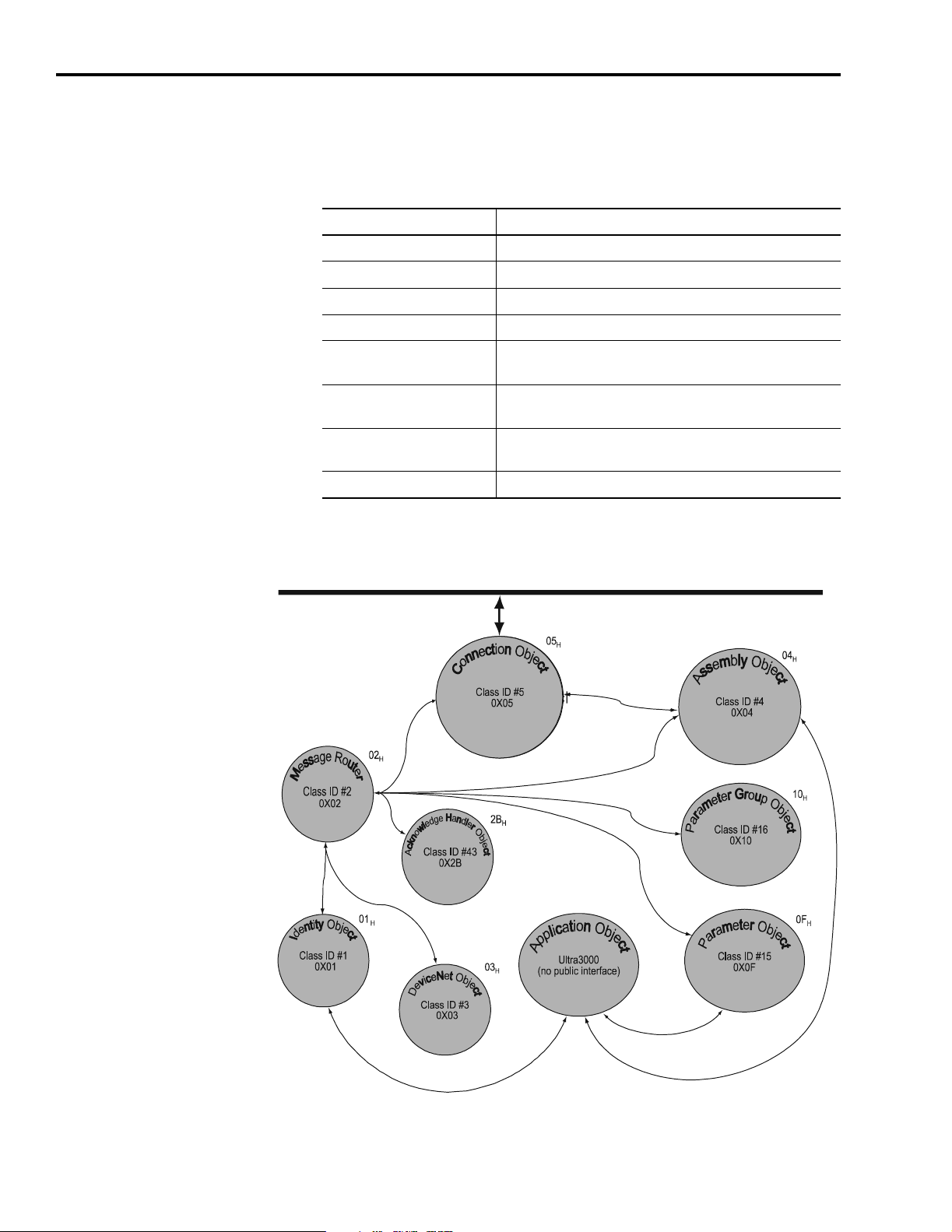
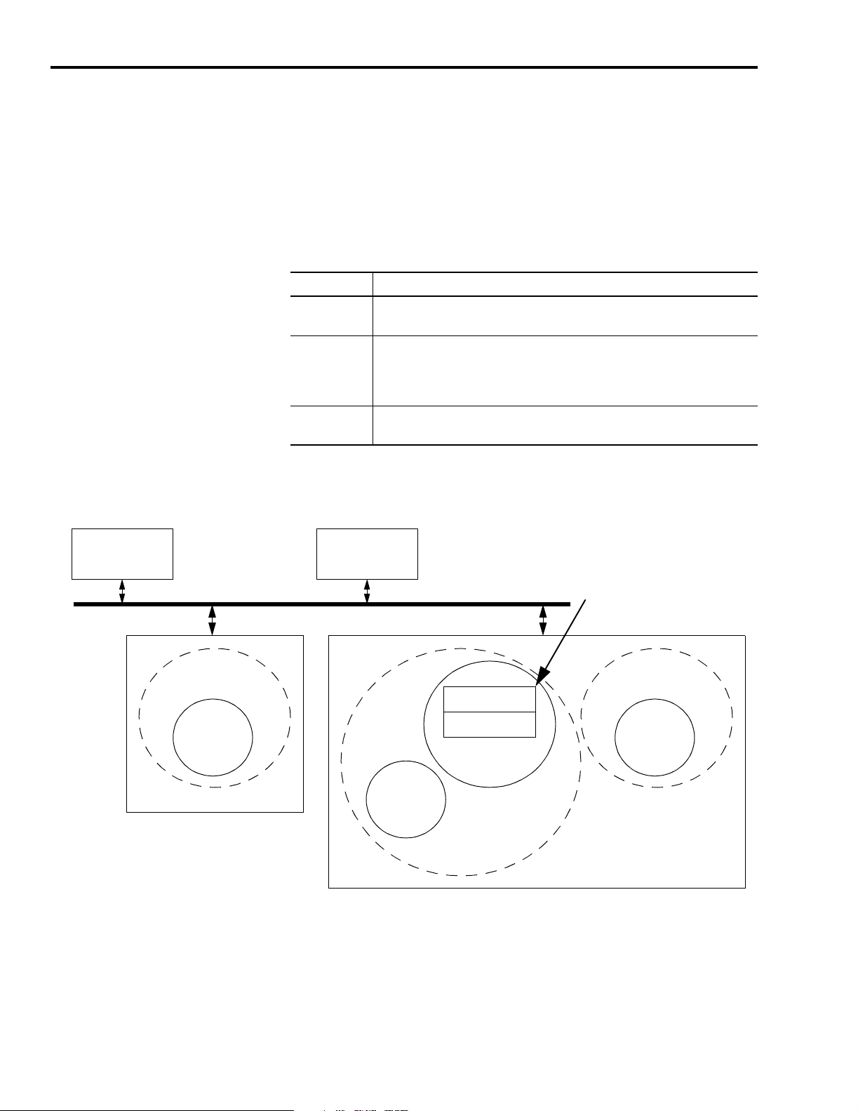
Object Model
The Object Model diagram on Page 2-2 depicts the objects supported
in the Ultra3000 Drive with DeviceNet. The following table indicates
the object classes present in this device, and the number of instances
present in each class.
Object Class Number of Instances
Identity 2
Message Router 1
DeviceNet 1
Assembly 18
Connection 2 - I/O
6 - Explicit
Parameter 1059 - Indexing Drive
298 - Non-indexing Drive
Parameter Group 16 - Indexing Drive
14 - Non-indexing Drive
Acknowledge Handler 1
Figure 2.1
Object Model
DeviceNet
Node
DeviceNet Network
Publication 2098-RM004A-EN-P – August 2002
Page 19

Programming Reference 2-3
How Objects Affect Behavior
The objects in the Ultra3000 Drive with DeviceNet affect it’s behavior
as shown in the table below.
Object Effect on Behavior
Message Router No effect
DeviceNet Configures port attributes (node address, data rate, and BOI)
Assembly Defines I/O data format
Connection Contains the number of logical ports into or out of the device
Parameter Provides a public interface to the device configuration data
Parameter Group Provides an aid to device configuration
Acknowledge Handler Manages the reception of message acknowledgments
The Defined Object Interface
The objects in the Ultra3000 Drive with DeviceNet have the interface
listed in the following table.
Object Interface
Message Router Explicit Messaging Connection Instance
DeviceNet Message Router
Assembly I/O Connection or Message Router
Connection Message Router
Parameter Message Router
Parameter Group Message Router
Acknowledge Handler I/O Connection or Message Router
Publication 2098-RM004A-EN-P – August 2002
Page 20
2-4 Programming Reference
Object Addressing
The Media Access Control Identifier (MAC ID) is the common basis for
logically addressing separate physical components across DeviceNet.
The MAC ID is a unique integer assigned to each DeviceNet node that
distinguishes it specifically from among other nodes on the same
network. The MAC ID often is referred to as the node address. Each
MAC ID is further identified with the following address components:
Component Description
Class ID The Class ID is a unique integer value assigned to each Object Class
accessible from the network. The Ultra3000 supports an 8-bit Class ID.
Instance ID The Instance ID is a unique identification assigned to an Object Instance
that identifies it among all Instances of the same Class.
It is also possible to address the Class itself by utilizing the Instance ID
value zero (0). The Ultra3000 supports an 16-bit Instance ID.
Attribute ID The Attribute ID is a unique identification assigned to a Class Attribute
and/or Instance Attribute.
Figure 2.2
Node Objects
DeviceNet Node 1 DeviceNet Node 2
MACID#1 MACID#2
DeviceNet Network
DeviceNet Node 3 DeviceNet Node 4
Object
Class #5
Instance
#1
Attribute #1
Attribute #2
Instance
#2
MACID#3
Instance
#1
Object
Class #5
MACID#4:
Object Class #5
Instance #2
Attribute #1
Object
Class #3
Instance
#1
MACID#4
Publication 2098-RM004A-EN-P – August 2002
Page 21

Programming Reference 2-5
Data Type Definitions
The following mnemonics define the Ultra3000 with DeviceNet data
types.
Mnemonic Description
ARRAY Sequence of Data
BOOL Boolean (1 byte)
BYTE Bit String, (1 byte)
DINT Signed Double Integer (4 bytes)
DWORD Bit String, (4 bytes)
EPATH DeviceNet Path Segments
INT Signed Integer (2 bytes)
SHORT_STRING Character String
(1 byte length indicator, 1 byte per character)
SINT Signed Short Integer (1 byte)
UDINT Unsigned Double Integer (4 bytes)
UINT Unsigned Integer (2 bytes)
USINT Unsigned Short Integer (1 byte)
WORD 16-bit Word, (2 bytes)
Identity Object
(Class ID 01
)
H
This object provides identification and general information about the
device.
Identity Object,
Attribute for Instance ID = 0 (Class Attributes)
AttrIDAccess
Rule
2 Get Max Instance UINT Maximum instance
Identity Object,
Instance ID = 1 - 2
Instance ID Description
1 Ultra3000
2 Ultra3000 Main Firmware
Attribute
Name
Type Description Semantics
of Values
The largest instance
number of an object
currently created in
this class level of the
device.
number of a created
object at this class
hierarchy level.
Publication 2098-RM004A-EN-P – August 2002
Page 22

2-6 Programming Reference
Identity Object,
Attributes of Instance ID = 1 - 2
Attr.IDAccess
Rule
Attribute
Name
Data
Ty pe
Description Semantics
1 Get Vendor ID UINT Identification
of each vendor
by number
2 Device Type Indication of
general type
of product.
3 Product Code Identification
of a particular
product of an
individual
vendor
of Values
01 = Rockwell Automation/
Allen-Bradley
Instance 1:
115 = Rockwell Automation
Miscellaneous
Instance 2:
105 = Subcomponent
Instance 1:
12 = 2098-DSD-005-DN
13 = 2098-DSD-010-DN
14 = 2098-DSD-020-DN
15 = 2098-DSD-030-DN
16 = 2098-DSD-075-DN
17 = 2098-DSD-150-DN
18 = 2098-DSD-005X-DN
19 = 2098-DSD-010X-DN
20 = 2098-DSD-020X-DN
21 = 2098-DSD-030X-DN
62 = 2098-DSD-075X-DN
63 = 2098-DSD-150X-DN
81 = 2098-DSD-HV030-DN
82 = 2098-DSD-HV050-DN
83 = 2098-DSD-HV100-DN
84 = 2098-DSD-HV150-DN
85 = 2098-DSD-HV220-DN
86 = 2098-DSD-HV030X-DN
87 = 2098-DSD-HV050X-DN
88 = 2098-DSD-HV100X-DN
89 = 2098-DSD-HV150X-DN
90 = 2098-DSD-HV220X-DN
Publication 2098-RM004A-EN-P – August 2002
4 Revision
Major
Minor
STRUCT
of:
USINT
USINT
Revision of
the item the
Identity Object
represents.
5 Status WORD This attribute
represents the
current status
of the entire
device. Its
value changes
as the state of
the device
changes.
6 Serial Number UDINT Serial number
of device
7 Product Name SHORT_
STRING
Readable
identification
Instance 2:
01 = Firmware
Major Revision
Minor Revision
See table: Identity Object,
Status Description of
Attribute ID = 5
Unique identifier for each
device.
Unique identifier for each
product.
Page 23

Programming Reference 2-7
Identity Object,
Status Description of Attribute ID = 5
Bit (s) Description Semantics of Values
0 Owned TRUE = device has an owner
1 Reserved, set to 0
2 Configured Always = 0
3 Reserved, set to 0
4, 5, 6, 7 Vendor specific
8 Minor recoverable
Always = 0
fault
9 Minor unrecoverable
Always = 0
fault
10 Major recoverable
TRUE if self diagnosis detects a major fault
fault
11 Major unrecoverable
Always = 0
fault
12, 13 Reserved, set to 0
14, 15
Identity Object,
Common Services
Service
Code
0E
H
05
H
11
H
Implemented for Service
Class Instance
Name
Yes Yes Get_Attribute_Single Returns the contents of the
No Reset Invokes the Reset service for
Yes n/a Find_Next_Object_
Instance
Service
Description
specified attribute.
the device.
Causes the specified class to
search and return a list of
instance IDs of existing
instances of the Identity
Object.
Reset Service
When the Identity Object receives a Reset request, it:
• determines if it can provide the type of reset requested
• responds to the request
• attempts to perform the type of reset requested
Publication 2098-RM004A-EN-P – August 2002
Page 24

2-8 Programming Reference
The Reset common service has the following object-specific
parameter:
Identity Object,
Reset Service
Name Data
Ty pe
Type USINT Type of Reset 0 = Emulate as closely as possible cycling power of
Description Semantics
of Values
the item the Identity Object represents. (default)
1 = Return as closely as possible to the out-of-box
configuration, then emulate cycling power as closely
as possible.
Message Router Object
(Class ID 02
)
H
The Message Router Object provides a messaging connection point
through which a Client may address a service to any object class or
instance residing in the physical device.
Message Router Object,
Attributes of Instance ID = 1
Attr.IDAccess
Rule
2 Get Number Available UINT Maximum number
3 Number active Number of
4 Active connections Array of
Attribute
Name
Data
Ty pe
UINT
Description Semantics
of Values
Count of the max
of connections
supported
connections
currently used by
system
components
A list of the
connection IDs of
the currently active
connections
number of
connections
supported
Current count of
the number of
connections
allocated to
system
communication
Array of system
connection IDs
Publication 2098-RM004A-EN-P – August 2002
Message Router Object,
Common Services
Service
Code
0E
H
Service
Name
Get_Attribute_Single Returns the contents of the specified attribute
Service
Description
Page 25

Programming Reference 2-9
DeviceNet Object
(Class ID 03
)
H
The DeviceNet Object provides configuration and status attributes of a
DeviceNet port.
DeviceNet Object,
Attribute of Instance ID = 0 (Class Attribute)
Attr. ID Access
Rule
1 Get Revision UINT Revision of the DeviceNet Object
DeviceNet Object,
Attributes of Instance ID = 1
Attr.IDAccess
Rule
1 Set MAC ID USINT Node Address Range 0-63
Set is only supported if the MAC ID is programmable.
Refer to Ultra3000 Digital Servo Drive Installation Manual listed on page P-2 for
Rotary DIP switch data setting.
2 Set Baud Rate Data Rate 0 = 125K,
Attribute
Name
Attribute
Name
Data
Description Semantics
Ty pe
Class definition upon which the
implementation is based.
Data Type Description Semantics
of Values
= 2
of Values
1 = 250K,
2 = 500K
Set is only supported if the data rate is programmable.
Refer to Ultra3000 Digital Servo Drive Installation Manual listed on page P-2 for
Rotary DIP switch data setting.
3 Set Bus OFF
Interrupt
(BOI)
4 Bus OFF
Counter
BOOL Bus-OFF Interrupt Default = 0
USINT Number of times
Controller Area
Network (CAN)
went to the
bus-OFF state
Range 0-255
Publication 2098-RM004A-EN-P – August 2002
Page 26

2-10 Programming Reference
DeviceNet Object,
Attributes of Instance ID = 1 (Continued)
Attr.IDAccess
Rule
Attribute
Name
5 Get Allocation
information
6MAC ID
Switch
Changed
7 Baud Rate
Switch
Changed
8MAC ID
Switch
Value
Data Type Description Semantics
of Values
STRUCT of:
BYTE
Allocation choice
(1 byte)
Refer to the
DeviceNet Object
definition in the
USINT
+ Master MAC
ID (1 byte)
DeviceNet
Specification
Range 0-63, 255
Modified via
Allocate only.
BOOL The Node
Address
switch(es) have
changed since
0 = No change
1 = Change since
last reset or
power-up
last
power-up/reset.
The Baud Rate
switch(es) have
changed since
last
0 = No change
1 = Change since
last reset or
power-up
power-up/reset.
USINT Actual value of
Range 0-63
Node Address
switch(es) or
EEPROM value if
programmable.
9 Baud Rate
Switch
Value
DeviceNet Object,
Common Services
Service
Code
0E
H
10
H
Service
Name
Get_Attribute_Single Returns the contents of the
Set_Attribute_Single Modifies the specified attribute.
Actual value of
Baud Rate
switch(es),
EEPROM value if
programmable, or
operating value
after an autobaud
was completed.
Service
Description
specified attribute.
Range 0-2
Publication 2098-RM004A-EN-P – August 2002
Page 27

DeviceNet Object,
Class Specific Services
Programming Reference 2-11
Assembly Object
(Class ID 04
)
H
Service
Code
4B
H
4C
H
Service
Name
Allocate_Master/Slave_
Connection_Set
Release_Group_2_
Identifier_Set
Service
Description
Requests the use of the Predefined
Master/Slave Connection Set.
Indicates that the specified
Connections within the Predefined
Master/Slave Connection Set are
no longer desired. These
connections are to be released
(deleted).
Assembly Objects are objects that bind attributes of multiple objects to
allow data to or from each object to be sent over a single connection.
The Ultra3000 with DeviceNet uses Assembly Objects to send data to
and from a Master (scanner) device over an I/O connection. The
terms Input and Output are defined from the scanner's point of view:
• Output Assemblies are defined as the information that is output by
the scanner and consumed by the Ultra3000.
• Input Assemblies are consumed by the scanner or are the scanner's
input.
The Ultra3000 with DeviceNet allows you to choose between various
Input and Output Assemblies, thereby choosing the data format of the
messages that are passed back and forth between the Ultra3000 with
DeviceNet and the scanner over the I/O connection. The following
parameters select the Assembly Object instances that are exchanged
over an I/O messaging connection.
Parameter
Instance
7 I/O Receive Select Selects the Assembly Object instance that is
8 Poll Transmit (Xmit)
9 COS/Cyclic Transmit
1
Refer to the section on the Parameter Object for more information about parameter instances.
Parameter Name Description
1
updated when a Poll/Change-of-State/Cyclic I/O
message is received by the drive. See page 2-48
for more information.
Selects the Assembly Object instance that is
Select
(Xmit) Select
transmitted by the drive over a Polled I/O
connection. See page 2-48 for more information.
Selects the Assembly Object instance that is
transmitted by the drive over a
Change-of-State/Cyclic I/O connection. See
page 2-49 for more information.
Publication 2098-RM004A-EN-P – August 2002
Page 28

2-12 Programming Reference
IMPORTANT
If the above parameters are modified, you must
perform one of the following before the modified
value(s) are active:
•Close any existing I/O messaging connection(s)
•Power cycle the drive
•Reset the drive
•Remove and reapply DeviceNet power to the drive.
In addition, you can send Explicit Messages to the Input and Output
Assemblies. Explicit Message writes to an Output Assembly can
perform control functions. Therefore, Explicit Message writes are only
allowed when the Master (scanner) is not actively controlling the drive
via I/O Messaging and the message write is done through a
connection with a time-out value not equal to zero. After a write, any
time-out or closure of the connection may cause the drive to fault.
Refer to Using Explicit Messaging to Control the Ultra3000. This
document may refer to Input and Output Assemblies as response and
command Assemblies respectively.
Assembly Object,
Attributes of Instance ID = 0 (Class Attributes)
Attr. ID Access
Rule
Attribute
Name
Data
Description Semantics
Ty pe
of Values
1 Get Revision UINT Revision of this
object.
2Max
Instance
Maximum instance
number of an
object currently
created in this
class level of the
device.
The current value
assigned to this attribute
is two (02).
The largest instance
number of a created
object at this class
hierarchy level.
Publication 2098-RM004A-EN-P – August 2002
Page 29

Programming Reference 2-13
The following Assembly Objects are implemented in the drive and
buffer I/O in the following fashion:
• RO = Read Only
• R/W = Read/Write
• R/PW = Read/Write Protected.
Refer to the sections Output Assemblies on page 2-14 and Input
Assemblies on page 2-33 for detailed information about the various
instances of the Assembly Objects.
Assembly Object,
Instance ID = 1 - 18
ID Data Type Access Size
(Bytes)
1 Static Output R/W 1 Handshake Bit, Feedback Data Pointer
2 Static Output R/W 7 Handshake Bit, Feedback Data Pointer,
3 Static Output R/PW 2 16 Bit Logic Command
4 Static Output R/PW 3 16 Bit Logic Command, Handshake Bit,
5 Static Output R/PW 8 16 Bit Logic Command, Handshake Bit,
6 Static Output R/PW 9 16 Bit Logic Command, Handshake Bit,
7 Static Output R/PW 4 32 Bit Logic Command
8 Static Output R/PW 5 32 Bit Logic Command, Handshake Bit,
9 Static Output R/PW 11 32 Bit Logic Command, Startup
10 Static Input RO 4 32 Bit Logic Status
11 Static Input RO 8 32 Bit Logic Status, and Feedback Data
Description
and Parameter Data Value
and Feedback Data Pointer
Feedback Data Pointer, and Command
Data Value
Feedback Data Pointer, and Parameter
Data Value
and Feedback Data Pointer
Commutation Done Bit, Feedback Data
Pointer, and Parameter Data Value
Value
12 Static Input RO 9 32 Bit Logic Status, Extra Status Byte
(with Write Data Status Bits,
Handshake Echo Bit, Feedback Data
Pointer and Feedback Data Value
13 Static Input RO 5 32 Bit Logic Status, Extra Status Byte
(with Write Data Status Bits, and
Handshake Echo Bit)
14 Static Input RO 8 Alternate 32 Bit Logic Status with
Write Data Status Bits (replacing
Position Limits Bits), and Feedback
Data Value
Publication 2098-RM004A-EN-P – August 2002
Page 30

2-14 Programming Reference
Assembly Object,
Instance ID = 1 - 18
ID Data Type Access Size
Description
(Bytes)
15 Static Input RO 4 Alternate 32 Bit Logic Status with
Write Data Status Bits (replacing
Position Limit Bits)
16 Static Input RO 4 Feedback Data Value
17 Static Input RO 5 Extra Status Byte (with Write Data
Status bits, Handshake Echo Bit, and
Feedback Data Pointer and Feedback
Data Value
18 Static Input RO 1 Extra Status Byte with Write Data
Status Bits, and Handshake Echo Bit
Assembly Object,
Attribute of Instances ID = 1 - 18
Attr ID Access
Rule
Attribute
Name
Data Type
3SetDataARRAY
Assembly Object,
Common Services
Service
Code
Implemented for Service
Class Instance
Name
Service
Description
0E
H
Yes Yes Get_Attribute_Single Returns the contents of the
specified attribute.
10E
H
No Set_Attribute_Single Modifies an attribute value.
Output Assemblies
There are nine output assemblies. An Output Assembly can consist of
a 16 or 32 bit Logic Command, a Handshake bit, Feedback Data
Pointer, and/or a Data Value.
Assembly Object,
Instance 1 - Output Assembly
Handshake Bit, Feedback Data Pointer
Byte Bit 7 Bit 6 Bit 5 Bit 4 Bit 3 Bit 2 Bit 1 Bit 0
0 Handshake Feedback Data Pointer
Publication 2098-RM004A-EN-P – August 2002
Page 31

Programming Reference 2-15
Assembly Object,
Instance ID = 2 - Output Assembly
Handshake Bit, Feedback Data Pointer, and Parameter Data Value
Byte Bit 7 Bit 6 Bit 5 Bit 4 Bit 3 Bit 2 Bit 1 Bit 0
0 Write
Data
Save to
NVMEM
Handshake Feedback Data Pointer
1 Parameter Instance - Low Byte
2 Parameter Instance - High Byte
3 Data Value - Low Byte
4 Data Value - Low Middle Byte
5 Data Value - High Middle Byte
6 Data Value - High Byte
Assembly Object,
Instance ID = 3 - Output Assembly
16 Bit Logic Command
Byte Bit 7 Bit 6 Bit 5 Bit 4 Bit 3 Bit 2 Bit 1 Bit 0
0 Preset Select 5Preset Select 4Preset Select 3Preset Select 2Preset Select 1Preset Select 0Follower
Enable
1 Enable Reset Faults Start Homing Remove
Offset
Disable Serial
Communicati
Define Home Start Index Operation
ons
Integrator
Inhibit
Mode
Override
Assembly Object,
Instance ID = 4 - Output Assembly
16 Bit Logic Command, Handshake Bit, and Feedback Data Pointer
Byte Bit 7 Bit 6 Bit 5 Bit 4 Bit 3 Bit 2 Bit 1 Bit 0
0 Preset Select 5Preset Select 4Preset Select 3Preset Select 2Preset Select 1Preset Select 0Follower
Enable
1 Enable Reset Faults Start Homing Remove
Offset
Disable Serial
Communicati
Define Home Start Index Operation
ons
Integrator
Inhibit
Mode
Override
2 Reserved Reserved Handshake Reserved Feedback Data Pointer
Publication 2098-RM004A-EN-P – August 2002
Page 32

2-16 Programming Reference
Assembly Object,
Instance ID = 5 - Output Assembly
16 Bit Logic Command, Handshake Bit, Feedback Data Pointer, and Command Data Value
Byte Bit 7 Bit 6 Bit 5 Bit 4 Bit 3 Bit 2 Bit 1 Bit 0
0 Preset Select 5Preset Select 4Preset Select 3Preset Select 2Preset Select 1Preset Select 0Follower
Enable
1 Enable Reset Faults Start Homing Remove
Offset
Disable Serial
Communicati
Define Home Start Index Operation
ons
2 Write Data Save to
Handshake Reserved Feedback Data Pointer
Integrator
Inhibit
Mode
Override
NVMEM
3 Command Data Pointer
4 Data Value - Low Byte
5 Data Value - Low Middle Byte
6 Data Value - High Middle Byte
7 Data Value - High Byte
Assembly Object,
Instance ID = 6 - Output Assembly
16 Bit Logic Command, Handshake Bit, Feedback Data Pointer, and Parameter Data Value
Byte Bit 7 Bit 6 Bit 5 Bit 4 Bit 3 Bit 2 Bit 1 Bit 0
0 Preset Select 5Preset Select 4Preset Select 3Preset Select 2Preset Select 1Preset Select 0Follower
Enable
Integrator
Inhibit
1 Enable Reset Faults Start Homing Remove
Offset
2 Write Data Save to
Handshake Reserved Feedback Data Pointer
NVMEM
3 Parameter Instance - Low Byte
4 Parameter Instance - High Byte
5 Data Value - Low Byte
6 Data Value - Low Middle Byte
7 Data Value - High Middle Byte
8 Data Value - High Byte
Publication 2098-RM004A-EN-P – August 2002
Disable Serial
Communicati
ons
Define Home Start Index Operation
Mode
Override
Page 33

Programming Reference 2-17
Assembly Object,
Instance ID = 7 - Output Assembly
32 Bit Logic Command
Byte Bit 7 Bit 6 Bit 5 Bit 4 Bit 3 Bit 2 Bit 1 Bit 0
0 Reserved Reserved Reserved Abort Homing Pause
Homing
Abort Index Pause Index Disable Serial
Communicati
ons
1 Reserved Reserved Preset Select 5Preset Select 4Preset Select 3Preset Select 2Preset Select 1Preset Select
0
2 Reserved Position
Strobe
Operation
Mode
Reserved Reserved Follower
Enable
Integrator
Inhibit
Define
Position
Override
3 Enable Reset Faults Start Homing Remove
Reserved Define Home Start Index Reset Drive
Offset
Assembly Object,
Instance ID = 8 - Output Assembly
32 Bit Logic Command, Handshake Bit, and Feedback Data Pointer
Byte Bit 7 Bit 6 Bit 5 Bit 4 Bit 3 Bit 2 Bit 1 Bit 0
0 Reserved Reserved Reserved Abort Homing Pause
Homing
Abort Index Pause Index Disable Serial
Communicati
ons
1 Reserved Reserved Preset Select 5Preset Select 4Preset Select 3Preset Select 2Preset Select 1Preset Select
0
2 Reserved Position
Strobe
Operation
Mode
Reserved Reserved Follower
Enable
Integrator
Inhibit
Define
Position
Override
3 Enable Reset Faults Start Homing Remove
Reserved Define Home Start Index Reset Drive
Offset
4 Reserved Reserved Handshake Reserved Feedback Data Pointer
Publication 2098-RM004A-EN-P – August 2002
Page 34

2-18 Programming Reference
Assembly Object,
Instance ID = 9 - Output Assembly
32 Bit Logic Command, Startup Commutation Done Bit, Feedback Data Pointer, and Parameter Data Value
Byte Bit 7 Bit 6 Bit 5 Bit 4 Bit 3 Bit 2 Bit 1 Bit 0
0 Reserved Reserved Reserved Abort Homing Pause
Homing
1 Reserved Reserved Preset Select 5Preset Select 4Preset Select 3Preset Select 2Preset Select 1Preset Select
2 Reserved Position
Strobe
3 Enable Reset Faults Start Homing Remove
4 Write Data Save to
NVMEM
5 Parameter Instance - Low Byte
6 Parameter Instance - High Byte
7 Data Value - Low Byte
8 Data Value - Low Middle Byte
9 Data Value - High Middle Byte
10 Data Value - High Byte
Operation
Mode
Override
Handshake Reserved Feedback Data Pointer
Reserved Reserved Follower
Reserved Define Home Start Index Reset Drive
Offset
Abort Index Pause Index Disable Serial
Communicati
ons
0
Enable
Integrator
Inhibit
Define
Position
Logic Commands
The first two or four bytes in several Output Assemblies are referred
to as the Logic Command. The logic command bits correspond to
functions available via the hardware digital inputs on the Ultra3000
Drive with DeviceNet. Parameter 10 - Logic Command Mask allows
you to mask off (zero) selected Logic Command bits to prevent the
bits activating any functions.
Note: The Logic Command Mask has a default value of zero.
Therefore, the Logic Command has no affect unless you modify
the Logic Command Mask.
Publication 2098-RM004A-EN-P – August 2002
Page 35

Programming Reference 2-19
The Enable bit in the logic command is OR'ed or AND'ed with a
hardware ENABLE as specified by Parameter 11 - Enable Behavior.
• If the ENABLE function has not been assigned to a hardware input,
then the hardware ENABLE is always active.
• If any of the other functions have not been assigned to a hardware
input, then the corresponding logic command bit controls the
function.
• If a function has been assigned to a hardware input, then the
corresponding logic command bit is OR'ed with the hardware
input.
IMPORTANT
A transition (0 -> 1) on a logic command bit is not
recognized if the corresponding hardware input is
active.
IMPORTANT
Toggling more than one bit at one time may produce
indeterminate behavior.
For example, changing a Preset Select and
transitioning the Start Index from 0 to 1 may cause
the previously selected Index to be executed.
Disable Serial Communications
This bit inhibits the drive's Serial Communications port operation.
• 1 = Serial Communications disabled
• 0 = Serial Communications enabled
Pause Index
This bit temporarily pauses an indexing sequence by decelerating to a
stop. The state of the input is continuously monitored to determine if
the motion should be stopped or if it may continue.
• 0 = Continue Indexing (Inactive)
• 1 = Pause Index
Note: This output requires an Indexing drive (e.g., 2098-DSD-xxxX).
Abort Index
A transition from zero to one (0 -> 1) terminates an indexing move.
Note: This output requires an Indexing drive (e.g., 2098-DSD-xxxX).
Publication 2098-RM004A-EN-P – August 2002
Page 36

2-20 Programming Reference
Pause Homing
This bit temporarily pauses a homing sequence by decelerating to a
stop. The state of the input is continuously monitored to determine if
the motion should be stopped or if it may continue.
• 0 = Continue Homing (Inactive)
• 1 = Pause Homing
Note: This output requires an Indexing drive (e.g., 2098-DSD-xxxX).
Abort Homing
A transition from zero to one (0 -> 1) terminates a homing sequence.
Note: This output requires an Indexing drive (e.g., 2098-DSD-xxxX).
Preset Select 0 to 5
Preset Select 0 to 2 are used in combination to select a Preset Current,
Preset Velocity, Preset Position, or Preset Follower Gearing Ratio.
Preset Select 0 to 5 are used in combination to select an Index. The 64
possible binary combinations of the Preset Selects are shown in the
following table.
Preset Preset
Select 5
0000000
1 0 0 0 0 0 1
2 0 0 0 0 1 0
3 0 0 0 0 1 1
4 0 0 0 1 0 0
5 0 0 0 1 0 1
6 0 0 0 1 1 0
7 0 0 0 1 1 1
.
.
.
61 1 1 1 1 0 1
.
.
.
Preset
Select 4
.
.
.
Preset
Select 3
.
.
.
Preset
Select 2
.
.
.
Preset
Select 1
.
.
.
Preset
Select 0
.
.
.
Publication 2098-RM004A-EN-P – August 2002
62 1 1 1 1 1 0
63111111
Page 37

Programming Reference 2-21
Define Position
When this input becomes active, it sets the Preset Position (parameter
304, 308, 312, 316, 320, 324, 328 or 332) selected by Preset Select 0 to
2, equal to the current drive position.
• 0 = Inactive
• 1 = Active
Note: This output requires an Indexing drive (e.g., 2098-DSD-xxxX).
Integrator Inhibit
This bit is used to zero the velocity loop integrator.
• 0 = No action
• 1 = Inhibit Integrator
Follower Enable
This bit allows the position loop to track the position command when
the drive is in the Follower Mode.
• 0 = Inactive
• 1 = Active
Position Strobe
An inactive state freezes the state of the motor encoder outputs. A
transition to an active state causes the drive to output a continuous
sequence of encoder counts until the absolute position is reached on
an external counter. This input is used in conjunction with the
Tracking output function.
• 0 = Inactive
• 1 = Active
Operation Mode Override
This bit selects whether drive uses Parameter 33 - Operation Mode or
Parameter 34 - Override Mode (Operation Mode Override) to
determine the command source.
• 0 = Parameter 33 - Operation Mode selects the command source
• 1 = Parameter 34 - Override Mode (Operation Mode Override)
selects the command source
Publication 2098-RM004A-EN-P – August 2002
Page 38

2-22 Programming Reference
Reset Drive
The drive resets anytime it receives a logic command with the Reset
Drive bit set high (except if the drive is enabled).
• 0 = Reset, or reboot, the hardware and firmware in the drive.
• 1 = Inactive
Start Index
A transition from zero to one (0 -> 1) of the Start Index bit begins an
index move if the drive's current Operation Mode is Indexing. A
transition is not recognized if a hardware input assigned as Start Index
is active.
Note: This output requires an Indexing drive (e.g.,2098-DSD-xxxX).
Define Home
A transition from zero to one (0 -> 1) causes the present motor
position to be selected as Home position. This means that the position
command is set to Parameter 344 - Home Position, and the position
feedback is simultaneously set to its appropriate value, according to
the position error.
Note: This output requires an Indexing drive (e.g., 2098-DSD-xxxX).
Remove Offset
A transition from zero to one (0 -> 1) causes the offset of the analog
command input to be measured (after averaging), and sets Parameter
254 - Analog Velocity Offset and Parameter 256 - Analog Current
Offset to the negative of this value.
Start Homing
A transition from zero to one (0 -> 1) initiates the homing routine.
Note: This output requires an Indexing drive (e.g., 2098-DSD-xxxX).
Publication 2098-RM004A-EN-P – August 2002
Page 39

Programming Reference 2-23
Reset Faults
A transition from zero to one (0 -> 1) resets any detected drive faults.
ATTENTION
If an Enable input is active, the drive may be enabled
and unexpected motion may occur.
!
Enable
This bit enables the drive (1 =enable, 0 = disable) depending on the
hardware ENABLE and Parameter 11 - Enable Behavior. You can
specify this bit to be OR'ed or AND'ed with the hardware ENABLE by
setting the Enable Behavior parameter.
• If Enable Behavior is set to 'Hardware OR DNet Input', then either a
hardware ENABLE or this bit can enable the drive.
• If Enable Behavior is set to 'Hardware AND DNet Input', both the
hardware ENABLE and this bit must be active to enable the drive.
IMPORTANT
Parameter 27 - Host Enable can temporarily disable
the drive regardless of the hardware ENABLE and
Logic Command Enable bit.
Handshake
A Handshake bit is included in some of the Output Assemblies and
the bit is echoed in some of the Input Assemblies. An application can
toggle the Handshake bit and confirm if the drive received the Output
Assembly by monitoring the Handshake Echo bit in the Input
Assembly. The drive does not use the Handshake bit for any other
purpose.
Feedback Data Pointer
The Feedback Data Pointer, contained in some of the Output Assemblies,
selects the Feedback Data Value that the Input Assembly should
return. The following table lists the available Feedback Data Values.
Publication 2098-RM004A-EN-P – August 2002
Page 40

2-24 Programming Reference
Refer to the Parameter Object instances to obtain scaling and units
information.
Feedback
Data Pointer
0 Position Command 132 DINT
1 Motor Position 134 DINT
2 Motor Velocity 140 DINT
3 Average Current 142 INT
4 Fault Status 123 DWORD
5 Extended Fault Status 124 WORD
6 Input Status 122 DWORD
7 Output Status 121 DWORD
8 Current Command 143 INT
9 Auxiliary Encoder Position 135 DINT
10 Position Error 133 DINT
11 Velocity Error 139 DINT
12 DC Bus Voltage 131 UINT
13 Velocity Command 138 DINT
Name
Parameter
Object
Instance
Data Type
(not filtered)
Parameter Data Value and Command Data Value Fields
The Parameter and Command Data Value fields contained in some of
the Output Assemblies allow you to write a parameter value to the
drive via I/O messaging. You can use Assemblies 2, 6, and 9 to write a
Data Value to the parameter object specified by Parameter Instance Low Byte and Parameter Instance - High Byte. See Parameter Object,
Instances ID = 1- 1059 on page 47. Assembly 5 also allows you to
write a Data Value to a parameter. However, Assembly 5 uses a
Command Data Pointer to select one of the parameters listed in the
Command Data table. Assembly 5 was implemented because it can be
sent in a non-fragmented I/O message. If Assembly 6 is sent via an
I/O message, the message is fragmented.
The Write Data bit is used to latch the Data Value that is located in the
last four bytes of the Output Assembly. A new data value will be
accepted by the drive on a zero to one transition (0 -> 1) of the Write
Data bit only if the Write Data Busy/Ack bit (located in the Input
Assembly) is low: 0 = idle, 1 = busy. The Write Data Busy/Ack bit is
cleared when the Write Data bit is set to zero and the drive is not busy
saving the data value. The Write Data and Write Data Busy/Ack bits
are ignored if the command assembly is updated via an explicit
message. By default, the value is only written to the drive as a
Publication 2098-RM004A-EN-P – August 2002
Page 41

Programming Reference 2-25
working value and is NOT saved in nonvolatile memory unless the
Save To NVMEM bit is set. The working value is lost if the drive is
reset or power cycled.
IMPORTANT
IMPORTANT
The nonvolatile memory has a limited number of
write cycles. Do not save parameter values to
nonvolatile memory (NVMEM) unless absolutely
necessary. In other words, minimize the number of
times parameter values are saved to nonvolatile
memory (NVMEM).
The drive acts on the Logic Command before reading
the Data Value. Therefore, the drive will accept the
Logic Command even though the Data Value may be
invalid. If an I/O message writes an invalid Data
Value, the drive sets the Write Data Error bit in the
Input Assembly. If the Data Value is updated via an
explicit message, the drive will return an error
response if the Data Value is invalid.
Publication 2098-RM004A-EN-P – August 2002
Page 42

2-26 Programming Reference
Command Data Table
The following table references the Command Data Pointer and
Parameter Object Instances for each Ultra3000 with DeviceNet
command.
Command
Data
Name Parameter Object
Instance
Pointer
0 NULL
1 Reset Faults 22
2 Reset Drive 23
3 Reset Personality 24
4 Reset I Peaks 25
5 Define Home Command 26
6 Host Enable 27
7 Host Control Mode 28
8 Velocity Setpoint 29
9 Current Setpoint 30
10 Setpoint Accel 31
11 Positive I Limit 37
12 Negative I Limit 38
13 Soft Overtravel 39
14 Positive Soft Position Limit 40
15 Negative Soft Position Limit, or
Acceleration Feedforward Gain - Kaff
16 Positive Decel Distance, or
Position Compare 1 Max
41
111
42
112
1
1
1
2
1
2
Publication 2098-RM004A-EN-P – August 2002
17 Negative Decel Distance, or
Position Compare 2 Max
43 1
113
18 Zero Speed Limit 44
19 Speed Window 45
20 Up to Speed 46
21 Position Window Size 47
22 Position Window Time 48
23 Position Compare 1 Type 49
24 Position Compare 1 Min 50
25 Position Compare 2 Type 51
26 Position Compare 2 Min 52
1
These commands are available only to indexing drives.
2
These commands are available only to non-indexing drives.
2
Page 43

Programming Reference 2-27
Command
Data
Name Parameter Object
Instance
Pointer
27 Velocity Loop P_Gain 53
28 Velocity Loop I_Gain 54
29 Velocity Loop D_Gain 55
30 Position Loop Kp Gain 56
31 Position Loop Ki Gain 57
32 Position Loop Kd Gain 58
33 Position Loop Kff Gain 59
34 Position Loop Ki Zone 60
35 Low Pass Filter 61
36 Low Pass Bandwidth 62
37 Digital Output Override 95
38 Override Analog Output 101
39 Analog Output Override 102
40 User Current Fault 103
41 User Velocity Limit 104
42 User Velocity Fault 105
43 Velocity Error Limit 106
44 Velocity Error Time 107
45 Position Error Limit 108
46 Position Error Time 109
47 Slew Enable 262
48 Slew Limit 263
49 Master Gear Count 0 264
50 Motor Gear Count 0 265
51 Master Gear Count 1 266
52 Motor Gear Count 1 267
53 Master Gear Count 2 268
54 Motor Gear Count 2 269
55 Master Gear Count 3 270
56 Motor Gear Count 3 271
57 Master Gear Count 4 272
58 Motor Gear Count 4 273
59 Master Gear Count 5 274
60 Motor Gear Count 5 275
61 Master Gear Count 6 276
62 Motor Gear Count 6 277
Publication 2098-RM004A-EN-P – August 2002
Page 44

2-28 Programming Reference
Command
Data
Name Parameter Object
Instance
Pointer
63 Master Gear Count 7 278
64 Motor Gear Count 7 279
65 Velocity Preset 0 280
66 Velocity Preset 1 281
67 Velocity Preset 2 282
68 Velocity Preset 3 283
69 Velocity Preset 4 284
70 Velocity Preset 5 285
71 Velocity Preset 6 286
72 Velocity Preset 7 287
73 Limit Preset Accel 288
74 Preset Accel Limit 289
75 Preset Decel Limit 290
76 Current Preset 0 291
77 Current Preset 1 292
78 Current Preset 2 293
79 Current Preset 3 294
80 Current Preset 4 295
81 Current Preset 5 296
82 Current Preset 6 297
83 Current Preset 7 298
84 3 Preset Position 0 304
85 3 Preset Position 0 Velocity 305
86 3 Preset Position 0 Accel 306
87 3 Preset Position 0 Decel 307
88 3 Preset Position 1 308
89 3 Preset Position 1 Velocity 309
90 3 Preset Position 1 Accel 310
91 3 Preset Position 1 Decel 311
92 3 Preset Position 2 312
93 3 Preset Position 2 Velocity 313
94 3 Preset Position 2 Accel 314
95 3 Preset Position 2 Decel 315
Publication 2098-RM004A-EN-P – August 2002
96 3 Preset Position 3 316
97 3 Preset Position 3 Velocity 317
98 3 Preset Position 3 Accel 318
Page 45

Programming Reference 2-29
Command
Data
Name Parameter Object
Instance
Pointer
99 3 Preset Position 3 Decel 319
100 3 Preset Position 4 320
101 3 Preset Position 4 Velocity 321
102 3 Preset Position 4 Accel 322
103 3 Preset Position 4 Decel 323
104 3 Preset Position 5 324
105 3 Preset Position 5 Velocity 325
106 3 Preset Position 5 Accel 326
107 3 Preset Position 5 Decel 327
108 3 Preset Position 6 328
109 3 Preset Position 6 Velocity 329
110 3 Preset Position 6 Accel 330
111 3 Preset Position 6 Decel 331
112 3 Preset Position 7 332
113 3 Preset Position 7 Velocity 333
114 3 Preset Position 7 Accel 334
115 3 Preset Position 7 Decel 335
116 3 Homing Type 336
117 3 Home Sensor Backoff 338
118 3 Homing Velocity 339
119 3 Homing Accel/ Decel 340
120 3 Home Offset Move 341
121 3 Homing Stop Decel 342
122 3 Home Sensor Polarity 343
123 3 Home Position 344
124 3 Homing Creep Velocity 345
125 3 Home Sensor Current 346
126 3 Start Homing Command 347
127 3 Abort Homing Command 348
128 3 Pause Homing Command 349
129 3 Host Index Number 350
130 3 Start Index Command 351
131 3 Abort Index Decel 356
132 3 Index 0 Type 357
133 3 Index 0 Distance/ Position 358
134 3 Index 0 Count 359
Publication 2098-RM004A-EN-P – August 2002
Page 46

2-30 Programming Reference
Command
Data
Name Parameter Object
Instance
Pointer
135 3 Index 0 Dwell 360
136 3 Index 0 Registration Distance 361
137 3 Index 0 Velocity 362
138 3 Index 0 Accel 363
139 3 Index 0 Decel 364
140 3 Index 0 Pointer 365
141 3 Index 0 Terminate 366
142 3 Index 1 Type 367
143 3 Index 1 Distance/ Position 368
144 3 Index 1 Count 369
145 3 Index 1 Dwell 370
146 3 Index 1 Registration Distance 371
147 3 Index 1 Velocity 372
148 3 Index 1 Accel 373
149 3 Index 1 Decel 374
150 3 Index 1 Pointer 375
151 3 Index 1 Terminate 376
152 3 Index 2 Type 377
153 3 Index 2 Distance/ Position 378
154 3 Index 2 Count 379
155 3 Index 2 Dwell 380
156 3 Index 2 Registration Distance 381
157 3 Index 2 Velocity 382
158 3 Index 2 Accel 383
159 3 Index 2 Decel 384
160 3 Index 2 Pointer 385
161 3 Index 2 Terminate 386
162 3 Index 3 Type 387
163 3 Index 3 Distance/ Position 388
164 3 Index 3 Count 389
165 3 Index 3 Dwell 390
166 3 Index 3 Registration Distance 391
167 3 Index 3 Velocity 392
Publication 2098-RM004A-EN-P – August 2002
168 3 Index 3 Accel 393
169 3 Index 3 Decel 394
170 3 Index 3 Pointer 395
Page 47

Programming Reference 2-31
Command
Data
Name Parameter Object
Instance
Pointer
171 3 Index 3 Terminate 396
172 3 Index 4 Type 397
173 3 Index 4 Distance/ Position 398
174 3 Index 4 Count 399
175 3 Index 4 Dwell 400
176 3 Index 4 Registration Distance 401
177 3 Index 4 Velocity 402
178 3 Index 4 Accel 403
179 3 Index 4 Decel 404
180 3 Index 4 Pointer 405
181 3 Index 4 Terminate 406
182 3 Index 5 Type 407
183 3 Index 5 Distance/ Position 408
184 3 Index 5 Count 409
185 3 Index 5 Dwell 410
186 3 Index 5 Registration Distance 411
187 3 Index 5 Velocity 412
188 3 Index 5 Accel 413
189 3 Index 5 Decel 414
190 3 Index 5 Pointer 415
191 3 Index 5 Terminate 416
192 3 Index 6 Type 417
193 3 Index 6 Distance/ Position 418
194 3 Index 6 Count 419
195 3 Index 6 Dwell 420
196 3 Index 6 Registration Distance 421
197 3 Index 6 Velocity 422
198 3 Index 6 Accel 423
199 3 Index 6 Decel 424
200 3 Index 6 Pointer 425
201 3 Index 6 Terminate 426
202 3 Index 7 Type 427
203 3 Index 7 Distance/ Position 428
204 3 Index 7 Count 429
205 3 Index 7 Dwell 430
206 3 Index 7 Registration Distance 431
Publication 2098-RM004A-EN-P – August 2002
Page 48

2-32 Programming Reference
Command
Data
Name Parameter Object
Instance
Pointer
207 3 Index 7 Velocity 432
208 3 Index 7 Accel 433
209 3 Index 7 Decel 434
210 3 Index 7 Pointer 435
211 3 Index 7 Terminate 436
212 3 Index 8 Type 437
213 3 Index 8 Distance/ Position 438
214 3 Index 8 Count 439
215 3 Index 8 Dwell 440
216 3 Index 8 Registration Distance 441
217 3 Index 8 Velocity 442
218 3 Index 8 Accel 443
219 3 Index 8 Decel 444
220 3 Index 8 Pointer 445
221 3 Index 8 Terminate 446
222 3 Index 9 Type 447
223 3 Index 9 Distance/ Position 448
224 3 Index 9 Count 449
225 3 Index 9 Dwell 450
226 3 Index 9 Registration Distance 451
227 3 Index 9 Velocity 452
228 3 Index 9 Accel 453
229 3 Index 9 Decel 454
230 3 Index 9 Pointer 455
231 3 Index 9 Terminate 456
232 3 Index 0 Absolute Direction 997
233 3 Index 1 Absolute Direction 998
234 3 Index 2 Absolute Direction 999
235 3 Index 3 Absolute Direction 1000
236 3 Index 4 Absolute Direction 1001
237 3 Index 5 Absolute Direction 1002
238 3 Index 6 Absolute Direction 1003
239 3 Index 7 Absolute Direction 1004
Publication 2098-RM004A-EN-P – August 2002
220 3 Index 8 Absolute Direction 1005
241 3 Index 9 Absolute Direction 1006
242 3 Acceleration Feedforward Gain - Kaff 111
Page 49

Programming Reference 2-33
Command
Data
Name Parameter Object
Instance
Pointer
243 3 Position Compare 1 Max 112
244 3 Position Compare 2 Max 113
3
These commands are available only to indexing drives.
Input Assemblies
There are nine input assemblies. An input assembly can consist of a
32 bit Logic Status, an Extra Status Byte, and/or a Feedback Data
Value .
Assembly Object,
Instance ID = 10 - Input Assembly
32 Bit Logic Status
Byte Bit 7 Bit 6 Bit 5 Bit 4 Bit 3 Bit 2 Bit 1 Bit 0
0 Startup
Commutatio
n Done
Tracking Axis Homed Registered In Dwell In Motion End of
Sequence
At Home
1 Position
Compare 2
2 Drive
Enabled
Position
Compare 1
At Index 1
Position
Up To Speed Negative
Current Limit
At Index 0
Position
Positive
Current Limit
Negative
Overtravel
Within
Speed
Window
Positive
Overtravel
Negative
Hardware
Overtravel
Zero Speed Within
Position
Window
Positive
Hardware
Overtravel
In Position
3 Drive Ready Brake Active Reserved Reserved Reserved Reserved Fault Disable DC Bus
Charged
Assembly Object,
Instance ID = 11 - Input Assembly
32 Bit Logic Status, and Feedback Data Value
Byte Bit 7 Bit 6 Bit 5 Bit 4 Bit 3 Bit 2 Bit 1 Bit 0
0 Startup
Commutation
Tracking Axis Homed Registered In Dwell In Motion End of
Sequence
At Home
Done
1 Position
Compare 2
2 Drive Enabled Up To Speed Negative
Position
Compare 1
At Index 1
Position
Current Limit
At Index 0
Position
Positive
Current Limit
Negative
Overtravel
Within Speed
Window
Positive
Overtravel
Negative
Hardware
Overtravel
Zero Speed Within
Position
Positive
Hardware
Overtravel
In Position
Window
3 Drive Ready Brake Active Reserved Reserved Reserved Reserved Fault Disable DC Bus
Charged
4 Feedback Data Value - Low Byte
Publication 2098-RM004A-EN-P – August 2002
Page 50

2-34 Programming Reference
Assembly Object,
Instance ID = 11 - Input Assembly
32 Bit Logic Status, and Feedback Data Value
Byte Bit 7 Bit 6 Bit 5 Bit 4 Bit 3 Bit 2 Bit 1 Bit 0
5 Feedback Data Value - Low Middle Byte
6 Feedback Data Value - High Middle Byte
7 Feedback Data Value - High Byte
Assembly Object,
Instance ID = 12 - Input Assembly
32 Bit Logic Status, Extra Status Byte (with Write Data Status Bits, Handshake Echo Bit, Feedback Data Pointer and
Feedback Data Value
Byte Bit 7 Bit 6 Bit 5 Bit 4 Bit 3 Bit 2 Bit 1 Bit 0
0 Startup
Commutation
Tracking Axis Homed Registered In Dwell In Motion End of
Sequence
At Home
Done
1 Position
Compare 2
2 Drive Enabled Up To Speed Negative
Position
Compare 1
At Index 1
Position
Current Limit
At Index 0
Position
Positive
Current Limit
Negative
Overtravel
Within Speed
Window
Positive
Overtravel
Negative
Hardware
Overtravel
Zero Speed Within
Position
Positive
Hardware
Overtravel
In Position
Window
3 Drive Ready Brake Active Reserved Reserved Reserved Reserved Fault Disable DC Bus
Charged
4 Write Data
Busy/Ack
Write Data
Error
Handshake
Echo
Reserved Feedback Data Pointer
5 Feedback Data Value - Low Byte
6 Feedback Data Value - Low Middle Byte
7 Feedback Data Value - High Middle Byte
8 Feedback Data Value - High Byte
Publication 2098-RM004A-EN-P – August 2002
Page 51

Programming Reference 2-35
Assembly Object,
Instance ID = 13 - Input Assembly
32 Bit Logic Status, Extra Status Byte (with Write Data Status Bits, and Handshake Echo Bit)
Byte Bit 7 Bit 6 Bit 5 Bit 4 Bit 3 Bit 2 Bit 1 Bit 0
0 Startup
Commutation
Tracking Axis Homed Registered In Dwell In Motion End of
Sequence
At Home
Done
1 Position
Compare 2
2 Drive Enabled Up To Speed Negative
Position
Compare 1
At Index 1
Position
Current Limit
At Index 0
Position
Positive
Current Limit
Negative
Overtravel
Within Speed
Window
Positive
Overtravel
Negative
Hardware
Overtravel
Zero Speed Within
Position
Positive
Hardware
Overtravel
In Position
Window
3 Drive Ready Brake Active Reserved Reserved Reserved Reserved Fault Disable DC Bus
Charged
4 Write Data
Busy/Ack
Write Data
Error
Handshake
Echo
Reserved Reserved Reserved Reserved Reserved
Assembly Object,
Instance ID = 14 - Input Assembly
Alternate 32 Bit Logic Status with Write Data Status Bits (replacing Position Limits Bits), and Feedback Data Value
Byte Bit 7 Bit 6 Bit 5 Bit 4 Bit 3 Bit 2 Bit 1 Bit 0
0 Startup
Commutation
Tracking Axis Homed Registered In Dwell In Motion End of
Sequence
At Home
Done
1 Write Data
Busy/Ack
2 Drive Enabled Up To Speed Negative
Write Data
Error
At Index 1
Position
Current Limit
At Index 0
Position
Positive
Current Limit
Negative
Overtravel
Within Speed
Window
Positive
Overtravel
Negative
Hardware
Overtravel
Zero Speed Within
Position
Positive
Hardware
Overtravel
In Position
Window
3 Drive Ready Brake Active Reserved Reserved Reserved Reserved Fault Disable DC Bus
Charged
4 Feedback Data Value - Low Byte
5 Feedback Data Value - Low Middle Byte
6 Feedback Data Value - High Middle Byte
7 Feedback Data Value - High Byte
Publication 2098-RM004A-EN-P – August 2002
Page 52

2-36 Programming Reference
Assembly Object,
Instance ID = 15 - Input Assembly
Alternate 32 Bit Logic Status with Write Data Status Bits (replacing Position Limit Bits)
Byte Bit 7 Bit 6 Bit 5 Bit 4 Bit 3 Bit 2 Bit 1 Bit 0
0 Startup
Commutation
Tracking Axis Homed Registered In Dwell In Motion End of
Sequence
At Home
Done
1 Write Data
Busy/Ack
2 Drive Enabled Up To Speed Negative
Write Data
Error
At Index 1
Position
Current Limit
At Index 0
Position
Positive
Current Limit
Negative
Overtravel
Within Speed
Window
Positive
Overtravel
Negative
Hardware
Overtravel
Zero Speed Within
Position
Positive
Hardware
Overtravel
In Position
Window
3 Drive Ready Brake Active Reserved Reserved Reserved Reserved Fault Disable DC Bus
Charged
Publication 2098-RM004A-EN-P – August 2002
Page 53

Programming Reference 2-37
Assembly Object,
Instance ID = 16 - Input Assembly
Feedback Data Value
Byte Bit 7 Bit 6 Bit 5 Bit 4 Bit 3 Bit 2 Bit 1 Bit 0
0 Feedback Data Value - Low Byte
1 Feedback Data Value - Low Middle Byte
2 Feedback Data Value - High Middle Byte
3 Feedback Data Value - High Byte
Assembly Object,
Instance ID = 17 - Input Assembly
Extra Status Byte (with Write Data Status bits, Handshake Echo Bit, and Feedback Data Pointer and Feedback Data Value
Byte Bit 7 Bit 6 Bit 5 Bit 4 Bit 3 Bit 2 Bit 1 Bit 0
0 Write Data
Busy/Ack
Write Data
Error
Handshake
Echo
Reserved Feedback Data Pointer
1 Feedback Data Value - Low Byte
2 Feedback Data Value - Low Middle Byte
3 Feedback Data Value - High Middle Byte
4 Feedback Data Value - High Byte
Assembly Object,
Instance ID = 18 - Input Assembly
Extra Status Byte with Write Data Status Bits, and Handshake Echo Bit
Byte Bit 7 Bit 6 Bit 5 Bit 4 Bit 3 Bit 2 Bit 1 Bit 0
0 Write Data
Busy/Ack
Write Data
Error
Handshake
Echo
Reserved Reserved Reserved Reserved Reserved
Publication 2098-RM004A-EN-P – August 2002
Page 54

2-38 Programming Reference
Logic Status
The first four bytes in some of the Input Assemblies are referred to as
the Logic Status. The Logic Status consists of 32 bits.
At Home
This bit indicates that the position command is equal to the Parameter
344 - Home Position.
Note: This output requires an Indexing drive (e.g., 2098-DSD-xxxX).
End of Sequence
This bit indicates all iterations of the index move have been
completed.
Note: This output requires an Indexing drive (e.g., 2098-DSD-xxxX).
In Motion
This bit indicates an index move is active and the motor is moving.
Note: This output requires an Indexing drive (e.g., 2098-DSD-xxxX).
In Dwell
Indicates the motor is holding position in an index move and waiting
for the commanded dwell time.
Note: This output requires an Indexing drive (e.g., 2098-DSD-xxxX).
Registered
This bit indicates the Registration Sensor has been detected and the
move has been adjusted, for this iteration of the index.
Note: The Registration Distance must be larger than the distance
required to stop or the move is not adjusted.
Note: This output requires an Indexing drive (e.g., 2098-DSD-xxxX).
Publication 2098-RM004A-EN-P – August 2002
Axis Homed
This bit indicates that the homing routine has completed.
Note: This output requires an Indexing drive (e.g., 2098-DSD-xxxX).
Page 55

Programming Reference 2-39
Tracking
This bit indicates that the motor position has been output and the
encoder outputs are now tracking the motor encoder inputs. This
output is used in conjunction with the Position Strobe input function.
Startup Commutation Done
This bit indicates that the drive has completed its commutation
initialization algorithm.
Positive Hardware Overtravel
This bit indicates a motor integral limit switch has been encountered
in the positive travel direction.
Note: This overtravel is not the Positive Hardware Overtravel initiated
by a digital input to the drive.
Negative Hardware Overtravel
This bit indicates a motor integral limit switch has been encountered
in the negative travel direction.
Note: This overtravel is not the Negative Hardware Overtravel initiated
by a digital input to the drive.
Positive Overtravel
This bit indicates that the positive soft position limit, Parameter 40, has
been exceeded, or the positive overtravel hardware input has become
active, or the motor’s positive integral limit (if this signal exists) has
been reached.
Negative Overtravel
This bit indicates that the negative soft position limit, Parameter 41,
has been exceeded, or the negative overtravel hardware input has
become active, or the motor’s negative integral limit (if this signal
exists) has been reached.
At Index 0 Position
An active state indicates the commanded motor position is equal to
the position defined by Index 0. This output functions only after the
axis has been homed.
Note: This output requires an Indexing drive (e.g., 2098-DSD-xxxX).
Publication 2098-RM004A-EN-P – August 2002
Page 56

2-40 Programming Reference
At Index 1 Position
An active state indicates the commanded motor position is equal to
the position defined by Index 1. This output functions only after the
axis has been homed.
Note: This output requires an Indexing drive (e.g., 2098-DSD-xxxX).
Position Limit 1
An active state indicates the condition defined by Parameter 49
(Position Compare 1 Type), Parameter 50 (Position Compare 1 Min),
and Parameter 112 (Position Compare 1 Max), for Position Compare 1
is true. If the drive has not been homed, the Position Limit 1 bit is
inactive.
Note: This output requires an Indexing drive (e.g., 2098-DSD-xxxX).
Position Limit 2
An active state indicates the condition defined by Parameter 51
(Position Compare 2 Type), Parameter 52 (Position Compare 2 Min),
and Parameter 113 (Position Compare 2 Max) for Position Compare 2
is true. If the drive has not been homed, the Position Limit 2 bit is
inactive.
Note: This output requires an Indexing drive (e.g., 2098-DSD-xxxX).
In Position
This bit indicates that the position error has been less than the
Parameter 47 - Position Window Size value for longer than the
Parameter 48 - Position Window Time value, and the speed is less
than the Parameter 44 - Zero Speed Limit setting.
Within Position Window
This bit indicates that the position error has been less than the
Parameter 47 - Position Window Size value for longer than the
Parameter 48 - Position Window Time value.
Zero Speed
Publication 2098-RM004A-EN-P – August 2002
This bit indicates that the speed is less than the Parameter 44 - Zero
Speed Limit setting.
Page 57

Programming Reference 2-41
Within Speed Window
This bit indicates that the velocity error is less than the Parameter 45 Speed Window value.
Positive Current Limit
Indicates that the drive current is being limited in the positive
direction.
Negative Current Limit
Indicates that the drive current is being limited in the negative
direction.
Up To Speed
This bit indicates the motor velocity feedback is greater than the
Parameter 46 - Up to Speed value.
Drive Enabled
This bit indicates if the power stage of the drive is enabled. For the
power stage to be enabled, the software and/or hardware ENABLE
inputs must be active, Parameter 27 - Host Enable must be enabled,
and the drive cannot have any 'disabling' faults.
DC Bus Charged
This bit indicates if the DC bus is energized.
Fault Disable
This bit indicates that a fault has occurred that caused the drive to
disable.
Brake Active
This bit indicates whether any digital output assigned as a BRAKE
output is active. If this bit is zero, then any BRAKE output is inactive
and the motor brake is applied. If this bit is one, then any BRAKE
output is active, and the motor brake is released so the motor can
move.
Drive Ready
Indicates that the drive is operational and does not have a 'disabling'
fault.
Publication 2098-RM004A-EN-P – August 2002
Page 58

2-42 Programming Reference
Handshake Echo
The Handshake Echo bit is included in some of the Input Assemblies.
The Handshake Echo bit is zero if the selected Output Assembly does
not contain a Handshake bit. An application can toggle the
Handshake bit in the Output Assembly and confirm if the drive
received the Output Assembly by monitoring the Handshake Echo bit
in an Input Assembly. The drive does not use the Handshake bit for
any other purpose.
DeviceNet Communication Fault Action
You can configure the Ultra3000 Drive with DeviceNet to perform a
specific action if the Output (command) Assembly is not periodically
updated after the I/O (or explicit) messaging connection has been
established and Parameter 7 - I/O Receive Select is set to a non-zero
value. The Output Assembly may not get updated for a several
reasons:
• the messaging connection is closed
• the scanner (Master) is placed into program mode
• the DeviceNet cable is unplugged
By default, the Ultra3000 Drive with DeviceNet will fault and clear the
logic command. You can configure the drive to take a different action
by configuring the following parameters:
• Idle Fault Action — Parameter 13
• Comm Fault Action — Parameter 14
• Faulted Logic Command — Parameter 15
The Ultra3000 Drive with DeviceNet will execute the Idle Fault Action
if the Master (scanner) sends I/O idle messages (zero-length
messages). The Comm Fault Action will be invoked if a
communication fault occurs such as the DeviceNet cable being
unplugged. The Idle Fault Action and Comm Fault Action parameters
allow you to configure the Ultra3000 Drive with DeviceNet to take
one of the following actions if a communication problem occurs that
Publication 2098-RM004A-EN-P – August 2002
Page 59

Programming Reference 2-43
prevents the Output (command) Assembly Object from being
updated:
• Fault/ Zero Data — The Ultra3000 Drive with DeviceNet faults and
the logic command is cleared
• Fault/ Hold Last — The Ultra3000 Drive with DeviceNet faults and
the last logic command received is latched
• Zero Data — The logic command is cleared
• Hold Last — The last logic command received is latched
• Fault Configure — The Faulted Logic Command parameter specifies
the logic command value. The Ultra3000 Drive with DeviceNet does
not fault. Refer to Using the Fault Configured Input on page 2-43.
Using the Fault Configured Input
You can select a constant value for the logic command in the event of
a controller (scanner) mode change or error. This constant value is
referred to as the Faulted Logic Command. When the controller is
placed in program mode or a DeviceNet network fault occurs, the
logic command to the drive can be set to automatically switch to the
value specified by the Faulted Logic Command — Parameter 15.
If you intend to use the Fault Configure Input, you must do the
following:
1. Set the desired value for the Faulted Logic Command.
2. Set the Idle Fault Action parameter and/or the Comm Fault Action
parameter to Fault Config.
Publication 2098-RM004A-EN-P – August 2002
Page 60

2-44 Programming Reference
Using Explicit Messaging to Control the Ultra3000
Explicit messages provide multi-purpose, point-to-point
communication paths between two devices. It is possible to control
the drive through explicit messaging on DeviceNet by following
particular guidelines and by writing to various Assembly Objects that
are buffering the I/O data. Although it is possible to control the drive
by writing to various parameter objects, you should consider using the
Assembly Objects for controlling the drive. The guidelines are as
follows:
• Write to the various Assembly Objects that are buffering the I/O
data.
• Write access to any Assembly Object is not allowed if the message
is passed through a connection whose expected packet rate (EPR)
is zero or if I/O data is being sent over an I/O messaging
connection.
• The drive marks any explicit connection after allowing a write to an
Assembly Object through the connection.
• If a marked explicit connection times out based on the EPR, then
the fault action will be that configured for Communication Loss
over the I/O connection, Comm Fault Action — Parameter 14.
• If a marked explicit connection is deleted, then the fault action will
be that configured for Idle over the I/O connection, Faulted Logic
Command — Parameter 15.
• Multiple explicit connections can write/overwrite the control I/O if
they meet the guidelines specified. Each connection will be
marked individually within the drive.
• If the drive gets allocated/re-allocated by a controller such that
valid I/O data is being sent to the drive, or if an Idle condition
from the allocating controller is transitioned back to valid data,
then all marked explicit connections will be reset to unmarked and
future writes blocked.
• If a marked connection has its Expected Packet Rate (EPR) value
reset to zero (0) after being marked, then the connection will
become unmarked.
Publication 2098-RM004A-EN-P – August 2002
IMPORTANT
Do not use Explicit Messaging to set parameter
objects that are changed frequently. An Explicit Set
causes an NVMEM write. The nonvolatile memory
has a limited number of write cycles.
Note: Explicit Get commands have no effect on
NVMEM.
Page 61

Programming Reference 2-45
Connection Object
The Connection Object manages the internal resources associated
with both I/O and Explicit Messaging Connections. The specific
(Class ID 05
)
H
instance generated by the Connection Class is referred to as a
Connection Instance or a Connection Object. A Connection Object
within a particular module actually represents one of the end-points of
a connection.
DeviceNet Connection Object,
Instance ID = 1 - 10
InstanceIDInstances
1 Group 2 Explicit Message Connection
2 Poll I/O Connection
4 Change-of-State or Cyclic I/O Connection
6-10 Group 3 Explicit Message Connections
DeviceNet Connection Object,
Attributes of Instances ID = 1 - 10 /
Attr ID Access
Rule
1 Get State USINT State of the Connection
Attribute
Name
Data Type Description
2 Instance Type I/O or Message Connection
3 Transport_class_trigger BYTE Defines the behavior of the Connection
4 Produced_connection_id UINT CAN identifier to transmit on
5 Consumed_connection_id CAN identifier to receive on
6 Initial_comm_characteristics BYTE Defines the Message Group(s) associated with this
Connection
7 Produced_connection_size UINT Maximum number of bytes transmitted across this
Connection
8 Consumed_connection_size Maximum number of bytes received across this
Connection
9 Set Expected_packet_rate Defines timing associated with this Connection
12 Watchdog_timeout_action USINT Defines how to handle Inactivity/Watchdog timeouts
13 Get Produced_connection_path_
length
14 Produced_connection_path EPATH Specifies the Application Object whose data is to be
15 Consumed_connection_path_len
gth
16 Consumed_connection_path EPATH Specifies the Application Object(s) that are to receive
UINT Number of bytes in the produced_connection_path
attribute
produced by this Connection object
UINT Number of bytes in the Consumed_connection_path
attribute
the data consumed by this Connection
17 Set Production_inhibit_time UINT Defines minimum time between new data production
for COS connections.
Publication 2098-RM004A-EN-P – August 2002
Page 62

2-46 Programming Reference
DeviceNet Connection Object,
Common Services
Service Code Service Name Service Description
0E
10
05
H
H
H
Get_Attribute_Single Returns the contents of the specified attribute.
Set_Attribute_Single Modifies the specified attribute.
Reset Used to reset the Inactivity/Watchdog Timer associated with a Connection Object
Parameter Object
The DeviceNet Parameter Object provides the interface to the
Ultra3000 Drive with DeviceNet configuration data. It supplies a full
(Class ID 0F
)
H
description of the parameter, including its minimum and maximum
values and a readable text string describing the parameter. The
instances start at one and increment with no gaps.
Parameter Object,
Attributes for Instance ID = 0 (Class Attributes)
Attr ID Access
Rule
1 Get Revision UINT Revision of this object Current value = 01
2 Max Instances Maximum instance number of an
8 Parameter Class
9 Configuration
Name Data
Ty pe
WORD Bit field that describe parameters Bit 0 = supports parameter instances
Descriptor
UINT Instance number of the configuration
Assembly
Instance
Description Semantics of Values
The largest instance number of a created
object currently created in this class
level of the device
assembly
object at this class hierarchy level
Bit 1 = full attributes
Bit 2 = nonvolatile storage save command
Bit 3 = params are stored in nonvolatile
storage
0 = configuration assembly not supported
Publication 2098-RM004A-EN-P – August 2002
The table Parameter Instance on page 2-47 lists the parameter
instances implemented in the Ultra3000 Drive with DeviceNet. The
table Parameter Object Instance Attributes on page 2-97 lists the
instance attributes of the parameter object. A parameter value is
accessed via Attribute 1 of a parameter instance. Additional
information about the parameter object is located beginning on
Page 2-99.
IMPORTANT
Some parameters cannot be modified while the
Ultra3000 Drive with DeviceNet is enabled. The drive
returns the error code, 10
- Device State Conflict, if
h
you attempt to modify one of these parameters while
the drive is enabled.
Page 63

Programming Reference 2-47
IMPORTANT
If Explicit Messages are to be used frequently to
change the value of parameter objects, refer to
Parameter 114 - Parameter Object Write Behavior. By
default, an Explicit Message Set_Attribute_Single
service causes a nonvolatile memory (NVMEM)
write. However, the nonvolatile memory has a
limited number of write cycles. Change Parameter
114 - Parameter Object Write Behavior to 1 - No
NVMEM Writes to prevent writing the nonvolatile
memory. Parameter values will continue to be
written to volatile memory (RAM).
•Parameters 22–26, 63, 347–349, and 351 (which
have a No Action (0) selection) are not saved in
volatile or non-volatile memory.
•Parameters 27–30, 95, 101–102, and 350 are not
saved in non-volatile memory, but are saved in
volatile memory.
Note: Explicit Get commands have no effect on
NVMEM.
Parameter Object,
Instances ID = 1- 1059
Parameter
Instance
1 Set Drive Name SHORT_
2 Get Main Firmware
3 Get DN-SW Node
4 Get DN-SW Data
Access
Rule
Parameter
Name
Version
Address
Rate
Data
Type
STRING
SHORT_
STRING
USINT 1 DeviceNet Node Address (Mac_ID) switch setting.
USINT 1 DeviceNet Data Rate switch setting.
Data Size
(Bytes)
1 byte
length
indicator, 1
byte per
character
1 byte
length
indicator, 1
byte per
character
Units /
Scale
Description
The name of the drive, up to 32 characters long.
The version of drive firmware, in the format
XX.YY.ZZ, where:
• XX = major revision
• YY = minor revision
• ZZ = maintenance revision (not displayed if zero).
0 - 125 kps
1 - 250 kps
2 - 500 kps
3 - Autobaud
4 - Programmable
5 - Programmable
6 - Programmable
7 - Programmable
8 - Programmable
9 - Programmable
Publication 2098-RM004A-EN-P – August 2002
Page 64

2-48 Programming Reference
Parameter Object,
Instances ID = 1- 1059
Parameter
Instance
5 Set DN-NV Node
Access
Rule
Parameter
Name
Address
Data
Type
Data Size
(Bytes)
Units /
Scale
Description
USINT 1 The programmed nonvolatile DeviceNet Node
Address (Mac_ID).
Range: 0 to 63
Default: 63
6 Set DN-NV Data Rate USINT 1 The programmed nonvolatile DeviceNet Data Rate.
0 - 125 kps (default)
1 - 250 kps
2 - 500 kps
3 - Autobaud
7 Set I/O Receive
Select
USINT 1 Selects the output (consumed) assembly that is
updated when a Polled, Change-of-State, or Cyclic
I/O Message is received by the drive. If the value is
modified, you have to either close any existing I/O
Messaging connection(s), power cycle the drive,
reset the drive, or remove and reapply DeviceNet
power for the drive to use the modified value. Refer
to the Assembly Object for information on the data
format.
0 - No Data Consumed (default)
1 - Assembly Instance 1
2 - Assembly Instance 2
3 - Assembly Instance 3
4 - Assembly Instance 4
5 - Assembly Instance 5
6 - Assembly Instance 6
7 - Assembly Instance 7
8 - Assembly Instance 8
9 - Assembly Instance 9
8 Set Poll Transmit
(Xmit) Select
USINT 1 Selects the input (produced) assembly that is
transmitted by the drive over a Polled I/O Messaging
connection. If the value is modified, you have to
either close any existing I/O Messaging
connection(s), power cycle the drive, reset the drive,
or remove and reapply DeviceNet power for the drive
to use the modified value. Refer to the Assembly
Object for information on the data format.
0 - Assembly Instance 10 (default)
1 - Assembly Instance 11
2 - Assembly Instance 12
3 - Assembly Instance 13
4 - Assembly Instance 14
5 - Assembly Instance 15
6 - Assembly Instance 16
7 - Assembly Instance 17
8 - Assembly Instance 18
Publication 2098-RM004A-EN-P – August 2002
Page 65

Parameter Object,
Instances ID = 1- 1059
Programming Reference 2-49
Parameter
Instance
Access
Rule
Parameter
Name
9 Set COS/Cyclic
Transmit (Xmit)
Select
10 Set Logic Command
Mask
Data
Type
Data Size
(Bytes)
Units /
Scale
Description
USINT 1 Selects the response (produced) assembly that is
transmitted by the drive over a Change-of-State, or
Cyclic I/O Messaging connection. If the value is
modified, you have to either close any existing I/O
Messaging connection(s), power cycle the drive,
reset the drive, or remove and reapply DeviceNet
power for the drive to use the modified value. Refer
to the Assembly Object for information on the data
format.
0 - Assembly Instance 10 (default)
1 - Assembly Instance 13
2 - Assembly Instance 15
DWORD 4 Masks bits of the logic command sent via Polled,
Cyclic, and Change-of-State I/O messages. If a bit is
clear (zero) in the Logic Command Mask, then the
corresponding bit in the logic command will be
cleared. The Logic Command Mask can not be
modified while the drive is enabled.
Bit 0 = Disable Serial
Bit 1 = Pause Index
Bit 2 = Abort Index
Bit 3 = Pause Homing
Bit 4 = Abort Homing
Bit 5 = Reserved
Bit 6 = Reserved
Bit 7 = Reserved
Bit 8 = Preset Select 0
Bit 9 = Preset Select 1
Bit 10 = Preset Select 2
Bit 11 = Preset Select 3
Bit 12 = Preset Select 4
Bit 13 = Preset Select 5
Bit 14 = Reserved
Bit 15 = Reserved
Bit 16 = Define Position
Bit 17 = Integrator Inhibit
Bit 18 = Follower Enable
Bit 19 = Reserved
Bit 20 = Reserved
Bit 21 = Operation Mode Override
Bit 22 = Position Strobe
Bit 23 = Reserved
Bit 24 = Reset Drive
Bit 25 = Start Index
Bit 26 = Define Home
Bit 27 = Reserved
Bit 28 = Remove CMD Offset
Bit 29 = Start Homing
Bit 30 = Fault Reset
Bit 31 = Enable Drive
Default: 0x00000000
Publication 2098-RM004A-EN-P – August 2002
Page 66

2-50 Programming Reference
Parameter Object,
Instances ID = 1- 1059
Parameter
Instance
Access
Rule
Parameter
Name
Data
Type
Data Size
(Bytes)
Units /
Scale
Description
11 Set Enable Behavior USINT 1 Used to determine if the drive can be enabled with
either the DeviceNet Enable or hardware ENABLE; or
if both enables have to be active.
0 - Hardware OR DNet Input (default)
1 - Hardware Enable AND DNet Input
12 Set Change-of-State
Mask
DWORD 4 The Change-of-State mask is used with
Change-of-State I/O messaging. If a particular bit is
set (one) in 'Change-of-State Mask', then a
Change-of-State I/O message will be produced
whenever the corresponding bit in Parameter 16 DNet I/O Status changes value. Otherwise, a
Change-of-State I/O message will not be produced.
Bit 0 = At Home
Bit 1 = End of Sequence
Bit 2 = In Motion
Bit 3 = In Dwell
Bit 4 = Registered
Bit 5 = Axis Homed
Bit 6 = Tracking
Bit 7 = Startup Commutation Done
Bit 8 = Positive Hardware Overtravel
(Motor Integral Limit)
Bit 9 = Negative Hardware Overtravel
(Motor Integral Limit)
Bit 10 = Positive Overtravel
Bit 11 = Negative Overtravel
Bit 12 = At Index 0 Position
Bit 13 = At Index 1 Position
Bit 14 = Position Compare 1/Write Data Error
Bit 15 = Position Compare 2/Write Data Busy
Bit 16 = In Position
Bit 17 = Within Position Window
Bit 18 = Zero Speed
Bit 19 = Within Speed Window
Bit 20 = Positive Current Limit
Bit 21 = Negative Current Limit
Bit 22 = Up to Speed
Bit 23 = Drive Enabled
Bit 24 = DC Bus Charged
Bit 25 = Fault Disable
Bit 26 = Reserved
Bit 27 = Reserved
Bit 28 = Reserved
Bit 29 = Reserved
Bit 30 = Brake
Bit 31 = Ready
Publication 2098-RM004A-EN-P – August 2002
Default: 0x0ffffffff
Page 67

Parameter Object,
Instances ID = 1- 1059
Programming Reference 2-51
Parameter
Instance
13 Set Idle Fault Action USINT 1 Determines the action the drive should take if the
ATTENTION
!
14 Set Comm Fault
Access
Rule
Parameter
Name
If you change the Idle Fault Action parameter's value, the user application may not be able to control the
product after a fault.
Risk of severe bodily injury or equivalent damage exists. The Idle Fault Action parameter allows you to
change the default configuration that would allow the module and associated drive to continue to
operate if communication is lost.
Precautions should be taken to assure that your settings for these parameters and your application do not
create bodily injury or equipment damage.
Refer to the sections DeviceNet Communication Fault Action on page 2-42 and Using the Fault Configured
Input on page 2-43.
Action
Data
Type
USINT 1 Determines the action the drive should take if the
Data Size
(Bytes)
Units /
Scale
Description
master sends a zero length I/O message to the drive,
which may occur if a PLC™ (master) is set to program
mode. No action is taken if the Parameter 7 - I/O
Receive Select specifies an I/O command message
that does not have a logic command.
0 - Fault / Zero Data (default)
1 - Fault / Hold Last Data
2 - Zero Data
3 - Hold Last Data
4 - Fault Configuration (Use data specified by
Parameter 15 - Faulted Logic Command).
drive detects a network failure while an I/O
messaging connection is active. No action is taken if
the Parameter 7 - I/O Receive Select specifies an I/O
command message that does not have a logic
command.
0 - Fault / Zero Data (default)
1 - Fault / Hold Last Data
2 - Zero Data
3 - Hold Last Data
4 - Fault Configuration (Use data specified by
Parameter 15 - Faulted Logic Command).
ATTENTION
!
If you change the Comm Fault Action parameter's value, the user application may not be able to control
the product after a fault.
Risk of severe bodily injury or equivalent damage exists. The Comm Fault Action parameter allows you to
change the default configuration that would allow the module and associated drive to continue to
operate if communication is lost.
Precautions should be taken to assure that your settings for these parameters and your application do not
create bodily injury or equipment damage.
Refer to the sections DeviceNet Communication Fault Action on page 2-42 and Using the Fault Configured
Input on page 2-43.
Publication 2098-RM004A-EN-P – August 2002
Page 68

2-52 Programming Reference
Parameter Object,
Instances ID = 1- 1059
Parameter
Instance
Access
Rule
Parameter
Name
15 Set Faulted Logic
Command
Data
Type
Data Size
(Bytes)
Units /
Scale
Description
DWORD 4 Provides the logic command data to the drive when
the drive receives an invalid I/O message or detects
a network failure while an I/O messaging connection
is active.
Bit 0 = Disable Serial
Bit 1 = Pause Index
Bit 2 = Abort Index
Bit 3 = Pause Homing
Bit 4 = Abort Homing
Bit 5 = Reserved
Bit 6 = Reserved
Bit 7 = Reserved
Bit 8 = Preset Select 0
Bit 9 = Preset Select 1
Bit 10 = Preset Select 2
Bit 11 = Preset Select 3
Bit 12 = Preset Select 4
Bit 13 = Preset Select 5
Bit 14 = Reserved
Bit 15 = Reserved
Bit 16 = Define Position
Bit 17 = Integrator Inhibit
Bit 18 = Follower Enable
Bit 19 = Reserved
Bit 20 = Reserved
Bit 21 = Operation Mode Override
Bit 22 = Position Strobe
Bit 23 = Reserved
Bit 24 = Reset Drive
Bit 25 = Start Index
Bit 26 = Define Home
Bit 27 = Reserved
Bit 28 = Remove CMD Offset
Bit 29 = Start Homing
Bit 30 = Fault Reset
Bit 31 = Enable Drive
IMPORTANT
The Faulted Logic Command does not affect those bits that have been masked off by Parameter 10 - Logic
Command Mask. Otherwise, the unmasked Faulted Logic Command bits are OR'ed with the corresponding
hardware inputs. The Enable bit may be configured to be OR'ed and AND’ed with the hardware Enable
input, refer to Parameter 11 - Enable Behavior.
Publication 2098-RM004A-EN-P – August 2002
Default: 0x00000000
Page 69

Parameter Object,
Instances ID = 1- 1059
Programming Reference 2-53
Parameter
Instance
Access
Rule
Parameter
Name
Data
Type
Data Size
(Bytes)
Units /
Scale
Description
16 Get DNet I/O Status DWORD 4 'DNet I/O Status' is the Logic Status field that can be
sent via Polled, Change-of-State, and Cyclic I/O
messages. The Logic Status is part of several
different input (response) assemblies. Refer to the
Assembly Object.
Bit 0 = At Home
Bit 1 = End of Sequence
Bit 2 = In Motion
Bit 3 = In Dwell
Bit 4 = Registered
Bit 5 = Axis Homed
Bit 6 = Tracking
Bit 7 = Startup Commutation Done
Bit 8 = Positive Hardware Overtravel
(Motor Integral Limit)
Bit 9 = Negative Hardware Overtravel
(Motor Integral Limit)
Bit 10 = Positive Overtravel
Bit 11 = Negative Overtravel
Bit 12 = At Index 0 Position
Bit 13 = At Index 1 Position
Bit 14 = Position Compare 1/Write Data Error
Bit 15 = Position Compare 2/Write Data Busy
Bit 16 = In Position
Bit 17 = Within Position Window
Bit 18 = Zero Speed
Bit 19 = Within Speed Window
Bit 20 = Positive Current Limit
Bit 21 = Negative Current Limit
Bit 22 = Up to Speed
Bit 23 = Drive Enabled
Bit 24 = DC Bus Charged
Bit 25 = Fault Disable
Bit 26 = Reserved
Bit 27 = Reserved
Bit 28 = Reserved
Bit 29 = Reserved
Bit 30 = Brake
Bit 31 = Ready
Publication 2098-RM004A-EN-P – August 2002
Page 70

2-54 Programming Reference
Parameter Object,
Instances ID = 1- 1059
Parameter
Instance
Access
Rule
Parameter
Name
Data
Type
Data Size
(Bytes)
Units /
Scale
Description
17 Get Logic Command DWORD 4 The logic command being used by the drive. Any bits
masked by the Logic Command Mask will be clear
(0). Refer to the Logic Command field in the output
(command) assemblies for the bit definition.
Bit 0 = Disable Serial
Bit 1 = Pause Index
Bit 2 = Abort Index
Bit 3 = Pause Homing
Bit 4 = Abort Homing
Bit 5 = Reserved
Bit 6 = Reserved
Bit 7 = Reserved
Bit 8 = Preset Select 0
Bit 9 = Preset Select 1
Bit 10 = Preset Select 2
Bit 11 = Preset Select 3
Bit 12 = Preset Select 4
Bit 13 = Preset Select 5
Bit 14 = Reserved
Bit 15 = Reserved
Bit 16 = Define Position
Bit 17 = Integrator Inhibit
Bit 18 = Follower Enable
Bit 19 = Reserved
Bit 20 = Reserved
Bit 21 = Operation Mode Override
Bit 22 = Position Strobe
Bit 23 = Reserved
Bit 24 = Reset Drive
Bit 25 = Start Index
Bit 26 = Define Home
Bit 27 = Reserved
Bit 28 = Remove CMD Offset
Bit 29 = Start Homing
Bit 30 = Fault Reset
Bit 31 = Enable Drive
18 Set Serial Address USINT 1 The drive's serial communications port address. If
the Serial Address is modified, then the drive must
be reset for the drive to use the new address.
Range: 0 to 253
Default: 0
Publication 2098-RM004A-EN-P – August 2002
Page 71

Parameter Object,
Instances ID = 1- 1059
Programming Reference 2-55
Parameter
Instance
19 Set Broadcast
Access
Rule
Parameter
Name
Address
Data
Type
Data Size
(Bytes)
Units /
Scale
Description
USINT 1 The address used by a host PC to issue a single
broadcast command to all connected Ultra3000
drives. The drive does not send a response to
commands received with the broadcast address. If
the Broadcast Address is modified, then the drive
must be reset for the drive to use the new address.
Note: If a drive's Broadcast Address and Serial
Address are set to the same value, the drive will
treat all serial commands as normal, point-to-point
commands, and will send a response to all
commands it processes.
Range: 0 to 255
Default: 255
20 Set Serial Baud Rate USINT 1 The baud rate for the drive's serial communications
port. If the baud rate is modified, then the drive must
be reset for the drive to use the new baud rate.
0 - 1200
1 - 2400
2 - 4800
3 - 9600
4 - 19200
5 - 38400 (default)
21 Set Frame Format USINT 1 The packet frame format for the drive's serial
communications port. If the frame format is
modified, then the drive must be reset for the drive
to use the new frame format.
0 - 7 Data Bits, Even Parity, 1 Stop Bit
1 - 7 Data Bits, Odd Parity, 1 Stop Bit
2 - 8 Data Bits, No Parity, 1 Stop Bit (default)
3 - 8 Data Bits, Even Parity, 1 Stop Bit
4 - 8 Data Bits, Odd Parity, 1 Stop Bit
22 Set Reset Faults USINT 1 Resets any drive faults. Motion may occur after
clearing drive faults if the drive is enabled.
0 - No Action (default)
1 - Reset
23 Set Reset Drive USINT 1 Resets, or reboots, the hardware and firmware in the
drive.
0 - No Action (default)
1 - Reset
Note: Set is not allowed if the drive is enabled.
24 Set Reset Personality USINT 1 Resets the drive's parameters by reinitializing them
to factory default settings. Stored faults in the fault
history remain unchanged.
0 - No Action (default)
1 - Reset
Note: The drive is reset after the parameters are
reinitialized.
Note: Set is not allowed if the drive is enabled.
Publication 2098-RM004A-EN-P – August 2002
Page 72

2-56 Programming Reference
Parameter Object,
Instances ID = 1- 1059
Parameter
Instance
25 Set Reset I Peaks USINT 1 Resets the peak value parameters to zero: Peak
26 Set Define Home
27 Set Host Enable USINT 1 Sets or returns the drive’s Host Enable flag. If set to
Access
Rule
Parameter
Name
Command
Data
Type
USINT 1 Causes the present motor position to be selected as
Data Size
(Bytes)
Units /
Scale
Description
Positive Position Error (Peak +Posn Error), Peak
Negative Position Error (Peak -Posn Error), Positive
Peak Current, and Negative Peak current.
0 - No Action (default)
1 - Reset
Home position. The position command is set to the
Home Position value, and the position feedback is
simultaneously set to its appropriate value,
according to the position error.
0 - No Action (default)
1 - Execute Command
'Enable' and the ENABLE input is active, the drive is
enabled. If set to 'Disable' or the ENABLE input is not
active, the drive is disabled. By default, Host Enable
is enabled. If the drive is reset or power cycled, the
'Host Enable' is automatically set to 'ENABLE'. The
Host Enable setting is not saved in nonvolatile
memory.
0 - Disable
1 - Enable (default)
ATTENTION
The Host Enable parameter allows you to temporarily disable the drive. Do not assume that the drive is
permanently disabled via the Host Enable parameter. Failure to comply may result in personal injury
and/or equipment damage.
!
28 Set Host Control
Mode
29 Set Velocity Setpoint DINT 4 Cnts /
USINT 1 Temporarily puts the drive into various tuning and
Sec
special operating modes. The Host Control Mode
setting is not saved in nonvolatile memory.
0 - Normal Mode (default)
1 - Setpoint Velocity
2 - Setpoint Current
3 - Host Index Mode (Indexing Only)
4 - Autotuning
5 - Step Velocity
6 - Step Position
The velocity command value used when the Host
Contrl Mode is 'Setpoint Velocity'. The drive will
ramp up, or ramp down, to the Velocity Setpoint at
the rate of acceleration set by Parameter 31 Setpoint Accel. The Velocity Setpoint is not saved in
nonvolatile memory.
Range: -0x7fffffff to 0x7fffffff
Default: 0
Publication 2098-RM004A-EN-P – August 2002
Page 73

Parameter Object,
Instances ID = 1- 1059
Programming Reference 2-57
Parameter
Instance
30 Set Current Setpoint INT 2 Amps /
Access
Rule
Parameter
Name
Data
Type
Data Size
(Bytes)
Units /
Scale
128
Description
The current command value used when Parameter
28 - Host Control Mode is set to 2 - Setpoint Current.
The Current Setpoint setting is not saved in
nonvolatile memory.
Range: -32767 to 32767
Default: 0
31 Set Setpoint Accel UDINT 4 Cnts /
Sec
The maximum rate of acceleration (or deceleration)
2
the drive will use to ramp up (or down) when the
drive is in Setpoint Velocity mode and the Velocity
Setpoint is changed.
Range: 0 to 0x7fffffff
Default: 100000
32 Set Motor Forward
Direction
USINT 1 Determines the positive motor direction.
0 - Normal (default) - A positive direction move
increases the encoder count.
1 - Reverse - A positive direction move decreases
the encoder count.
Note: Set is not allowed if the drive is enabled.
33 Set Operation Mode USINT 1 The drive's command source and operating mode.
0 - Analog Velocity Input (default)
1 - Analog Current Input
2 - Preset Velocity
3 - Preset Current
4 - Follower: Auxiliary Encoder
5 - Follower: Step / Direction
6 - Follower: Step Up / Step Down
7 - Indexing (Indexing Drive only)
8 - Analog Position (Indexing Drive only)
9 - Preset Position (Indexing Drive only)
Note: Set is not allowed if the drive is enabled.
34 Set Override Mode USINT 1 The drive's command source and operating mode
used when the Operation Mode Override input is
active.
0 - Analog Velocity Input (default)
1 - Analog Current Input
2 - Preset Velocity
3 - Preset Current
4 - Follower: Auxiliary Encoder
5 - Follower: Step / Direction
6 - Follower: Step Up / Step Down
7 - Indexing (Indexing Drive only)
8 - Analog Position (Indexing Drive only)
9 - Preset Position (Indexing Drive only)
Note: Set is not allowed if the drive is enabled.
Publication 2098-RM004A-EN-P – August 2002
Page 74

2-58 Programming Reference
Parameter Object,
Instances ID = 1- 1059
Parameter
Instance
Access
Rule
Parameter
Name
35 Set (Machine Cycle)
Position Rollover
36 Set Machine Cycle
Size
Data
Type
Data Size
(Bytes)
Units /
Scale
Description
USINT 1 Enables or disables the machine cycle position
rollover function. If enabled the position feedback
will rollover when it’s value reaches the Machine
Cycle Size.
0 - Disable (default)
1 - Enable
Note: This parameter is automatically set to Enable
(1) and cannot be changed when Single-Turn
Absolute mode is active (refer to Parameter 231 Single-Turn Absolute).
Note: Set is not allowed if the drive is enabled.
UDINT 4 Cnts The position feedback will rollover at the Machine
Cycle Size if Parameter 35, Position Rollover
parameter is set to 1 - Enable. For example, if
Machine Cycle Size is set to 1000, then the position
feedback will range between 0 to 999.
Range: 100 to 0x7fffffff
Default: 0x7fffffff
Note: This parameter is automatically set to One
Revolution (in counts) and cannot be changed when
Single-Turn Absolute mode is active (refer to
Parameter 231 - Single-Turn Absolute).
Note: Set is not allowed if the drive is enabled.
37 Set Positive I Limit USINT 1 % The positive current limit value. The value is a
percentage of the lesser of the intermittent (peak)
drive current rating and intermittent (peak) motor
current rating. During runtime, the drive limits
positive current to the lesser of the:
• Positive Current Limit,
• Analog Current Limit input,
• Intermittent Current rating of the drive, or
• Intermittent Current rating of the motor.
Range: 0 to 100
Default: 100
Publication 2098-RM004A-EN-P – August 2002
Page 75

Parameter Object,
Instances ID = 1- 1059
Programming Reference 2-59
Parameter
Instance
Access
Rule
Parameter
Name
Data
Type
Data Size
(Bytes)
Units /
Scale
Description
38 Set Negative I Limit USINT 1 % The negative current limit value. The value is a
percentage of the lesser of the intermittent (peak)
drive current rating and intermittent (peak) motor
current rating. During runtime, the drive limits
positive current to the lesser of the:
• Negative Current Limit,
• Analog Current Limit input,
• Intermittent Current rating of the drive, or
• Intermittent Current rating of the motor.
Range: 0 to 100
Default: 100
39 Set Soft Overtravel USINT 1 Enables or disables the software overtravel limit
checking.
0 - Disable (default)
1 - Enable
Note: This parameter instance is not available to
non-indexing drives. If invoked, a non-indexing drive
returns Reserved as the parameter name.
Note: The Soft Overtravel does not operate unless
the drive was previously homed.
40 Set Positive Soft
Position Limit
DINT 4 Cnts The absolute position that will cause a deceleration
to zero velocity when exceeded in the positive
direction.
Range: -0x7fffffff to 0x7fffffff
Default: 0x7fffffff
41 Set Negative Soft
Position Limit
Note: This parameter instance is not available to
non-indexing drives. If invoked, a non-indexing drive
returns Reserved as the parameter name.
Note: The Positive Soft Position Limit does not
operate unless the drive was previously homed.
DINT 4 Cnts The absolute positive that will cause a deceleration
to zero velocity when exceeded in the negative
direction.
Range: -0x7fffffff to 0x7fffffff
Default: -0x7fffffff (0x80000001)
Note: This parameter instance is not available to
non-indexing drives. If invoked, a non-indexing drive
returns Reserved as the parameter name.
Note: The Negative Soft Position Limit does not
operate unless the drive was previously homed.
Publication 2098-RM004A-EN-P – August 2002
Page 76

2-60 Programming Reference
Parameter Object,
Instances ID = 1- 1059
Parameter
Instance
42 Set Positive Decel
Access
Rule
Parameter
Name
Data
Type
Data Size
(Bytes)
Units /
Scale
DINT 4 Cnts The distance that an axis will travel when an
Distance
43 Set Negative Decel
DINT 4 Cnts The distance that an axis will travel when an
Distance
44 Set Zero Speed Limit UDINT 4 Cnts /
Sec
Description
overtravel limit has been reached in the positive
direction.
Range: 0 to 0x7fffffff
Default: 0
Note: This parameter instance is not available to
non-indexing drives. If invoked, a non-indexing drive
returns Reserved as the parameter name.
overtravel limit has been reached in the negative
direction.
Range: 0 to 0x7fffffff
Default: 0
Note: This parameter instance is not available to
non-indexing drives. If invoked, a non-indexing drive
returns Reserved as the parameter name.
A +/- range, or window, around zero velocity. If the
motor feedback velocity falls within this range, the
Zero Speed flag will be (or remain) set.
Range: 0 to 0x7fffffff
Default: 500
45 Set Speed Window UDINT 4 Cnts /
Secs
46 Set Up to Speed UDINT 4 Cnts /
Secs
47 Set Position Window
UDINT 4 Cnts The maximum amount of position error which will
Size
48 Set Position Window
USINT 1 mSec The minimum length of time the position error must
Time
A +/- range, or window, around the velocity
command. If the motor feedback velocity falls within
this range, the Speed Window flag will be (or
remain) set.
Range: 0 to 0x7fffffff
Default: 1000
If the motor feedback velocity is greater than or
equal to this value, the Up to Speed flag will be (or
remain) set.
Range: 0 to 0x7fffffff
Default: 100000
permit the In Position and the In Position Window
flags to be (or remain) set.
Range: 0 to 0x7fffffff
Default: 20
be less than the Position Window Size value, for the
In Position and the In Position Window flags to be (or
remain) set.
Range: 1 to 255
Default: 20
Publication 2098-RM004A-EN-P – August 2002
Page 77

Parameter Object,
Instances ID = 1- 1059
Programming Reference 2-61
Parameter
Instance
Access
Rule
Parameter
Name
49 Set Position Compare
1Type
50 Set Position Compare
1Min
Data
Type
Data Size
(Bytes)
Units /
Scale
Description
USINT 1 Selects the type of comparison that will determine if
the Position Compare 1 flag should be set.
0 - Greater Than (default) - The flag will be set if the
motor feedback position is greater than the
Position Compare 1 Min value.
1 - Less Than - The flag will be set if the motor
feedback position is less than the
Position Compare 1 Min value.
2 - Within Window - The flag will be set if the motor
feedback position is greater than
Position Compare 1 Min and less than Parameter
112 - Position Compare 1 Max.
3 - Outside Window - The flag will be set if the
motor feedback position is less than
Position Compare 1 Min or more than Position
Compare 1 Max.
Note: The Position Compare 1 Type does not operate
unless the drive was previously homed.
DINT 4 Cnts The position that will be compared to the motor
(auxiliary) feedback position to determine if the
Position Compare 1 flag should be set.
Range: -0x7fffffff to 0x7fffffff
Default: 0
51 Set Position Compare
2Type
52 Set Position Compare
2Min
USINT 1 Selects the type of comparison that will determine if
the Position Compare 2 flag should be set.
0 - Greater Than (default) - The flag will be set if the
motor feedback position is greater than the
Position Compare 2 Min value.
1 - Less Than - The flag will be set if the motor
feedback position is less than the
Position Compare 2 Min value.
2 - Within Window - The flag will be set if the motor
feedback position is greater than
Position Compare 2 Min and Less than Parameter
113 - Position Compare 2 Max.
3 - Outside Window - The flag will be set if the
motor feedback position is less than
Position Compare 2 Min or more than Position
Compare 2 Max.
Note: The Position Compare 2 Type does not operate
unless the drive was previously homed.
DINT 4 Cnts The position that will be compared to the motor
(auxiliary) feedback position to determine if the
Position Compare 2 flag should be set.
Range: -0x7fffffff to 0x7fffffff
Default: 0
Publication 2098-RM004A-EN-P – August 2002
Page 78

2-62 Programming Reference
Parameter Object,
Instances ID = 1- 1059
Parameter
Instance
Access
Rule
Parameter
Name
53 Set Velocity Loop
P_Gain
54 Set Velocity Loop
I_Gain
55 Set Velocity Loop
D_Gain
Data
Type
Data Size
(Bytes)
Units /
Scale
Description
UINT 2 The proportional gain for the velocity loop. The P
gain generates a control signal proportional to the
velocity error. Increasing the P gain improves
response time and increases the stiffness of the
system. Too high a P gain value causes instability;
too low a P gain value results in loose or sloppy
system dynamics.
Range: 0 to 4000
Default: 200
UINT 2 Integral gain for the velocity loop. The I gain
generates a control signal proportional to the
integral of the velocity error. I gain improves the
steady-state velocity performance of the system.
Increasing the integral gain generally increases the
ultimate positioning accuracy of the system.
However excessive integral gain results in system
instability.
Range: 0 to 4000
Default: 66
INT 2 Derivative gain value for the velocity loop. The D
gain generates a control signal proportional to
measured acceleration. Positive D gain reduces
velocity overshoot, and negative D gain should be
used only in systems that exhibit mechanical
resonance.
Range: -1000 to 1000
Default: 0
56 Set Position Loop Kp
Gain
57 Set Position Loop Ki
Gain
58 Set Position Loop Kd
Gain
59 Set Position Loop Kff
Gain
UINT 2 1/128 Proportional gain for the position loop. The Kp gain
generates a control signal proportional to the
position error. Kp gain changes the position loop
bandwidth and the settling time of the position loop.
Range: 0 to 4095
Default: 512
UINT 2 1/128 Integral gain for the position loop. Ki gain generates
a control signal proportional to the integral of the
velocity error.
Range: 0 to 4095
Default: 0
UINT 2 1/128 Derivative gain for the position loop. The Kd gain
generates a control signal proportional to measured
velocity. Kd provides damping to the position loop,
which can reduce overshoot.
Range: 0 to 4095
Default: 0
UINT 2 Feedforward gain for the position loop. The Kff gain
generates a feed forward signal proportional to the
commanded speed. Kff gain reduces position
following error. However high values can cause
position overshoot.
Range: 0 to 200
Default: 100
Publication 2098-RM004A-EN-P – August 2002
Page 79

Parameter Object,
Instances ID = 1- 1059
Programming Reference 2-63
Parameter
Instance
60 Set Position Loop Ki
Access
Rule
Parameter
Name
Zone
Data
Type
Data Size
(Bytes)
Units /
Scale
Description
UDINT 4 Cnts The region around the commanded position where
integral gain is active. If the position error is greater
than Ki Zone, the integrator is not active.
Range: 0 to 0x7fffffff
Default: 1000
61 Set Low Pass Filter USINT 1 Selects whether to enable or disable the drive's low
pass filter.
0 - Disable
1 - Enable (default)
62 Set Low Pass
Bandwidth
UINT 2 Hz The bandwidth of the low pass filter. This value
indicates the cutoff frequency of the low pass filter.
The filter reduces noise generated by encoder
resolution or mechanical resonance in the system.
Range: 1 to 992
Default: 150
63 Set Start Autotune
Command
USINT 1 Starts autotuning if the drive is enabled and
Parameter 28, Host Control Mode is set to 4 Autotuning.
0 - No Action (default)
1 - Execute Command
64 Set Tuning Direction USINT 1 Select the direction in which the motor rotates
during autotuning.
0 - Bi-Directional (default)
1 - Forward Only
2 - Reverse Only
65 Set Autotune
Maximum
Distance
UDINT 4 Cnts The maximum distance the motor will turn when
performing autotuning. The autotune distance
should be set as large as the application permits, so
that the autotune algorithm is able to collect
sufficient data to compute new tuning gains.
Range: 1 to 0x7fffffff
Default: 1000000
66 Set Autotune Step
Current
67 Set Tune Position
Step
USINT 1 % The current the drive will command when performing
autotuning. The value is a percentage of the lesser
of the intermittent (peak) drive current rating and
intermittent (peak) motor current rating. The
autotune current is normally set to 10%, but may
need to be increased in the presence of large
inertias or high friction. In these systems, higher
settings ensure that the autotune algorithm is able
to collect sufficient data to compute new tuning
gains.
Range: 1 to 100
Default: 10
UINT 2 Cnts The amplitude of the drive's commanded position
step (square wave) during manual position tuning.
Range: 1 to 32767
Default: 500
Publication 2098-RM004A-EN-P – August 2002
Page 80

2-64 Programming Reference
Parameter Object,
Instances ID = 1- 1059
Parameter
Instance
Access
Rule
Parameter
Name
68 Set Tune Position
Period
69 Set Tune Velocity
Step
70 Set Tune Velocity
Period
71 Set Motor Encoder
Interpolation
Data
Type
Data Size
(Bytes)
Units /
Scale
Description
UINT 2 mSec The period of the drive's commanded position step
(square wave) during manual position tuning.
Range: 1 to 32767
Default: 500
UDINT 4 Cnts /
Sec
The amplitude of the drive's commanded velocity
step (square wave) during manual velocity tuning.
Range: 1 to 0x7fffffff
Default: 10000
UINT 2 mSec The period of the drive's command velocity step
(square wave) during manual velocity tuning.
Range: 1 to 32767
Default: 500
USINT 1 The amount of interpolation to be used with
sine/cosine encoders. For example, if the
interpolation is set to x256, the drive interpolates
256 counts for every 1/4 line of the input sinusoid.
0 - x4
1 - x8
2 - x16
3 - x32
4 - x64
5 - x128
6 - x256 (default)
7 - x512
8 - x1024
72 Set Position
Feedback Source
73 Set Encoder Output
Signal
74 Set Motor Encoder
Divider
Note: Set is not allowed if the drive is enabled.
USINT 1 The source for position loop feedback.
0 - Motor Encoder (default)
1 - Auxiliary Encoder
Note: This parameter instance is not available to
non-indexing drives. If invoked, a non-indexing drive
returns Reserved as the parameter name.
USINT 1 Specifies the type of encoder output from the drive.
0 - Buffered (default) - The encoder input is passed
through the drive directly, without interpolation or
division.
1 - Divided - The encoder input is divided and then
output.
2 - Interpolated - The interpolated encoder counts
are output.
UINT 2 The amount of division used for generating the
encoder output signal. For example, if the Divider is
set to 4, the encoder output frequency will be 1/4
the encoder input frequency. This parameter is only
active if Divided is selected as the Encoder Output
Signal.
Range: 1 to 1000
Default: 4
th
Publication 2098-RM004A-EN-P – August 2002
Page 81

Parameter Object,
Instances ID = 1- 1059
Programming Reference 2-65
Parameter
Instance
Access
Rule
Parameter
Name
75 Set Maximum
Encoder Output
Frequency
76 Set Marker Output
Gating
77 Set Auxiliary Encoder
Load Count
Data
Type
Data Size
(Bytes)
Units /
Scale
Description
USINT 1 The encoder output frequency limit. This parameter
is active only if Divided or Interpolated is selected as
the Encoder Output Signal.
0 - 500 kHz (default)
1 - 1 MHz
2 - 4 MHz
3 - 8 MHz
USINT 1 Allows the drive to produce and use a more precise
marker signal.
0 - Not Gated - The drives uses and outputs the
normal marker input as received from the encoder.
(default)
1 - Gated with A and B - The marker output of the
drive is the logical AND of the marker input from the
encoder and the A and B inputs. This produces a
more precise marker signal for homing.
UINT 2 Cnts The Auxiliary Encoder Motor Count and Auxiliary
Encoder Load Count parameters specify the ratio of
encoder counts between the motor encoder and the
load encoder. The parameters are active only if the
The Position Feedback Source is selected to be
Auxiliary Encoder.
Range: 1 to 32767
Default: 1
78 Set Auxiliary Encoder
Motor Count
79 Set Auxiliary Encoder
Typ e
80 Set Auxiliary Encoder
Lines/Rev
81 Set Auxiliary Encoder
Lines/ Meter
INT 2 Cnts The Auxiliary Encoder Motor Count and Auxiliary
Encoder Load Count parameters specify the ratio of
encoder counts between the motor encoder and the
load encoder. The parameters are active only if the
Position Feedback Source is selected to be Auxiliary
Encoder.
Range: -32767 to 32767
Default: 1
USINT 1 The type of auxiliary encoder.
0 - Rotary Encoder (default)
1 - Linear Encoder
UINT 2 Auxiliary encoder lines per revolution. This
parameter is used only if the auxiliary encoder is a
rotary encoder.
Range: 100 to 64000
Default: 2000
UDINT 4 Auxiliary encoder lines per meter of travel. This
parameter is used only if the auxiliary encoder is a
linear encoder.
Range: 4000 to 10000000
Default: 10000
Publication 2098-RM004A-EN-P – August 2002
Page 82

2-66 Programming Reference
Parameter Object,
Instances ID = 1- 1059
Parameter
Instance
Access
Rule
Parameter
Name
82 Set Digital Input 1
Configuration
83 Set Digital Input 2
Configuration
84 Set Digital Input 3
Configuration
85 Set Digital Input 4
Configuration
86 Set Digital Input 5
Configuration
87 Set Digital Input 6
Configuration
88 Set Digital Input 7
Configuration
89 Set Digital Input 8
Configuration
Data
Type
Data Size
(Bytes)
Units /
Scale
Description
DWORD 4 Each digital input configuration parameter assigns
one or more functions to the corresponding Digital
DWORD 4
Input. Selecting a function will cause that function to
become active when the associated Digital Input
becomes active. If no functions are selected by a
DWORD 4
digital input configuration parameter, then the
corresponding Digital Input is unassigned.
DWORD 4
Bit 0 = Disable Serial Input
Bit 1 = Pause Index
DWORD 4
Bit 2 = Abort Index
Bit 3 = Pause Homing
DWORD 4
Bit 4 = Abort Homing
Bit 6 = Positive Hardware Overtravel
Bit 7 = Negative Hardware Overtravel
DWORD 4
Bit 8 = Preset Select 0
Bit 9 = Preset Select 1
Bit 10 = Preset Select 2
DWORD 4
Bit 11 = Preset Select 3
Bit 12 = Preset Select 4
Bit 13 = Preset Select 5
Bit 16 = Define Position
Bit 17 = Integrator Inhibit
Bit 18 = Follower Enable
Bit 19 = Forward Enable
Bit 20 = Reverse Enable
Bit 21 = Operation Mode Override
Bit 22 = Position Strobe
Bit 23 = Home Sensor
Bit 24 = Reset Drive
Bit 25 = Start Index
Bit 26 = Define Home Position
Bit 27 = Registration
Bit 28 = Remove Command Offset
Bit 29 = Start Homing
Bit 30 = Fault Reset
Bit 31 = Enable Drive
Publication 2098-RM004A-EN-P – August 2002
Defaults:
Parameter 82 = 0x80000000
Parameters 83-89 = 0x00000000
Note: Set is not allowed if the drive is enabled.
Page 83

Parameter Object,
Instances ID = 1- 1059
Programming Reference 2-67
Parameter
Instance
Access
Rule
Parameter
Name
90 Set Digital Output 1
Configuration
91 Set Digital Output 2
Configuration
92 Set Digital Output 3
Configuration
93 Set Digital Output 4
Configuration
94 Set Relay Output
Configuration
Data
Type
Data Size
(Bytes)
Units /
Scale
Description
DWORD 4 Each digital output configuration parameter assigns
one or more functions to the corresponding Digital
DWORD 4
Output (or Relay Output). Selecting a function will
cause the Digital Output to become active when the
associated function becomes active. If no functions
DWORD 4
are selected by a digital output configuration
parameter, then the corresponding Digital Output (or
DWORD 4
Relay Output) is unassigned.
Bit 0 = At Home
DWORD 4
Bit 1 = End of Sequence
Bit 2 = In Motion
Bit 3 = In Dwell
Bit 4 = Registered
Bit 5 = Axis Homed
Bit 6 = Tracking
Bit 7 = Startup Commutation Done
Bit 8 = Positive Hardware Overtravel
(Motor Integral Limit)
Bit 9 = Negative Hardware Overtravel
(Motor Integral Limit)
Bit 10 = Positive Overtravel
Bit 11 = Negative Overtravel
Bit 12 = At Index 0 Position
Bit 13 = At Index 1 Position
Bit 14 = Position Compare 1
Bit 15 = Position Compare 2
Bit 16 = In Position
Bit 17 = Within Position Window
Bit 18 = Zero Speed
Bit 19 = Within Speed Window
Bit 20 = Positive Current Limit
Bit 21 = Negative Current Limit
Bit 22 = Up to Speed
Bit 23 = Drive Enabled
Bit 24 = DC Bus Charged
Bit 25 = Fault Disable
Bit 26 = Reserved
Bit 27 = Reserved
Bit 28 = Reserved
Bit 29 = Reserved
Bit 30 = Brake
Bit 31 = Ready
Default = 0x00000000
Note: Set is not allowed if the drive is enabled.
Publication 2098-RM004A-EN-P – August 2002
Page 84

2-68 Programming Reference
Parameter Object,
Instances ID = 1- 1059
Parameter
Instance
95 Set Digital Output
Access
Rule
Parameter
Name
Override
Data
Type
Data Size
(Bytes)
Units /
Scale
Description
WORD 2 Allows you to write (override) selected digital
output(s). If one or more of the Override bits are set
to a one, then the Output and Relay State bits will
determine whether the overridden digital outputs
are active or inactive. For example, if the Digital
Output Override parameter is set to 0x0044, then
Digital Output 3 will be active. The Digital Output
Override setting is not saved in nonvolatile memory.
Bit 0 = Output 1 Override
Bit 1 = Output 2 Override
Bit 2 = Output 3 Override
Bit 3 = Output 4 Override
Bit 4 = Relay Override
Bit 5 = Reserved
Bit 6 = Reserved
Bit 7 = Reserved
Bit 8 = Output 1 State
Bit 9 = Output 2 State
Bit 10 = Output 3 State
Bit 11 = Output 4 State
Bit 12 = Relay State
Range: 0 to 0x1fff
Default: 0
96 Set Brake On Delay INT 2 mSec The time delay between enabling the drive and
activating a Brake output which releases the motor
brake. Negative values indicate the time that the
function is activated before enabling the drive.
Range: -32767 to 32767
Default: 0
97 Set Brake Off Delay INT 2 mSec The time delay between disabling the drive and
deactivating a Brake output to apply the motor
brake. If a drive fault occurs when a negative is
assigned to the Brake Off Delay, the drive is disabled
and the Brake is deactivated simultaneously.
Range: -32767 to 32767
Default: 0
98 Set Analog Output
Configuration
Publication 2098-RM004A-EN-P – August 2002
USINT 1 Selects a drive signal to be assigned to the analog
output.
0 - Unassigned (default)
1 - Position Command
2 - Position Error
7 - Position Feedback
16 - Current Command
17 - Average Current
22 - Velocity Feedback
23 - Velocity Command
24 - Velocity Error
36 - Current Feedback
Page 85

Parameter Object,
Instances ID = 1- 1059
Programming Reference 2-69
Parameter
Instance
Access
Rule
Parameter
Name
99 Set Analog Output
Scale
100 Set Analog Output
Offset
101 Set Override Analog
Output
102 Set Analog Output
Override
Data
Type
Data Size
(Bytes)
Units /
Scale
Description
INT 2 The analog output scale in units per volt. The units is
dependent on the signal selected by the Parameter
98 - Analog Output Configuration. Parameter 110 Analog Output Position Scale is used to scale the
analog output if a position signal is selected and the
Analog Output Scale is zero.
Range: -32767 to 32767
Default: 0
INT 2 mV The offset applied to the analog output.
Range: -10000 to 10000
Default: 0
USINT 1 The analog output override control flag determines if
you can write to the analog output directly. The
Override Analog Output setting is not saved in
nonvolatile memory.
0 - Normal (default)
1 - Override
INT 2 mV Sets the analog output value when Parameter 101,
Override Analog Output is set to 1 - Override. The
Analog Output Override setting is not saved in
nonvolatile memory.
Range: -10000 to 10000
Default: 0
103 Set User Current
Fault
104 Set User Velocity
Limit
105 Set User Velocity
Fault
106 Set Velocity Error
Limit
UINT 2 Amps /
128
The current level that will generate a fault when
exceeded by the average current. The drive
automatically protects itself and the motor when the
average current exceeds the drive or motor current
ratings, and this protection cannot be disabled.
However, you can specify a lower current fault level
with this parameter.
Range: 0 to 32767
Default: 32640
UDINT 4 Cnts /
Sec
The minimum velocity that will generate a User
Velocity fault. The drive automatically protects the
motor from exceeding its ratings, and this protection
cannot be disabled. However, you can specify a
lower velocity fault level with this parameter.
Range: 0 to 0x7fffffff
Default: 100000
USINT 1 Determines if the User Velocity fault detection is
enabled (turned on) or disabled.
0 - Disable (default)
1 - Enable
USINT 1 % of
max
motor
speed
The minimum velocity error which triggers the
Velocity Error fault.
Range: 1 to 100
Default: 25
Publication 2098-RM004A-EN-P – August 2002
Page 86

2-70 Programming Reference
Parameter Object,
Instances ID = 1- 1059
Parameter
Instance
Access
Rule
Parameter
Name
107 Set Velocity Error
Time
108 Set Position Error
Limit
109 Set Position Error
Time
110 Set Analog Output
Position Scale
111 Set Acceleration
Feedforward
Gain - Kaff
Data
Type
Data Size
(Bytes)
Units /
Scale
Description
UINT 2 mSec The minimum time which the velocity error must be
greater than the Velocity Error Limit to cause a
Velocity Error Fault.
Range: 0 to 65535
Default: 1000
UDINT 4 Cnts The minimum position error which triggers the
Following Error fault.
Range: 0 to 0x7fffffff
Default: 8000
UINT 2 mSec The minimum time during which the position error
must be greater than the Position Error Limit to
cause a Following Error fault.
Range: 0 to 65535
Default: 100
DINT 4 Cnts/V This parameter is used to scale the analog output
when Parameter 98 - Analog Output Configuration
selects a position signal and Parameter 99 - Analog
Output Scale is equal to zero.
Range: -0x7fffffff to 0x7fffffff
Default: 0
UINT 2 % Acceleration feedforward gain for the position loop.
The Kaff gain generates a feed forward signal
proportional to the commanded acceleration.
Kaff gain reduces position following error. However,
high values can cause position overshoot.
Range: 0 to 200
Default: 0
112 Set Position Compare
1 Max
113 Set Position Compare
2 Max
DINT 4 Cnts The position that will be compared to the motor
(auxiliary) feedback position to determine if the
Position Compare 1 flag should be set.
Range: -0x7fffffff to 0x7fffffff
Default: 0
DINT 4 Cnts The position that will be compared to the motor
(auxiliary) feedback position to determine if the
Position Compare 2 flag should be set.
Range: -0x7fffffff to 0x7fffffff
Default: 0
Publication 2098-RM004A-EN-P – August 2002
Page 87

Parameter Object,
Instances ID = 1- 1059
Programming Reference 2-71
Parameter
Instance
Access
Rule
Parameter
Name
114 Set Parameter Object
Write Behavior
Data
Type
Data Size
(Bytes)
Units /
Scale
Description
USINT 1 Determines whether the Set_Attribute_Single
(write) service to a parameter object will cause the
parameter value to be saved to both nonvolatile
(NVMEM) and volatile (RAM) memory or just to
volatile memory. By default, most parameter values
are written to both volatile and nonvolatile memory.
However, if the Parameter Object Write Behavior is
set to 1 - No NVMEM Writes, then parameter values
are only written to volatile memory.
0 - Writes to NVMEM (default)
1 - No NVMEM Writes
Note: This parameter (114) does not affect how
parameter values are saved when an I/O or explicit
message writes a parameter value via an Assembly
Object.
Note: This parameter (114) is always written to both
volatile and nonvolatile memory. Setting this
parameter to 1 - No NVMEM Writes allows a user to
frequently change parameter values without
exceeding the nonvolatile memory's limited number
of write cycles. Typically, a user will not modify this
parameter.
Note: Some parameter values are not saved to
nonvolatile memory. Example: Parameter 22 - Reset
Faults, Parameter 27 - Host Enable, Parameter 29 Velocity Setpoint.
115-119 Get Reserved USINT 1 Default: 0
Publication 2098-RM004A-EN-P – August 2002
Page 88

2-72 Programming Reference
Parameter Object,
Instances ID = 1- 1059
Parameter
Instance
Access
Rule
Parameter
Name
Data
Type
Data Size
(Bytes)
Units /
Scale
Description
120 Get Operating Mode USINT 1 The operating mode that the drive is currently in.
0 = Analog Velocity Input
1 = Analog Current Input
2 = Preset Velocity
3 = Preset Current
4 = Follower - Auxiliary Encoder
5 = Follower - Step / Direction
6 = Follower - Step Up / Step Down
7 = Indexing
8 = Analog Position
9 = Preset Position
10 - 15 = Reserved
16 = Setpoint Velocity
17 = Setpoint Current
18 = Host Index Mode
19 = Autotuning
20 = Step Velocity
21 = Step Position
22 = Encoder Index Alignment
23 = Commutation Diagnostics
24 = Motor Feedback Diagnostics
25 = Motor Marker Diagnostics
26 = Auxiliary Feedback Diagnostics
27 = Auxiliary Marker Diagnostics
28 - 31 = Reserved
32 = Disabled
33 = Fault Decel
34 = Homing
35 = Reserved
36 = Commutation Startup
37 = Start/Stop
Publication 2098-RM004A-EN-P – August 2002
Page 89

Parameter Object,
Instances ID = 1- 1059
Programming Reference 2-73
Parameter
Instance
Access
Rule
Parameter
Name
Data
Type
Data Size
(Bytes)
Units /
Scale
Description
121 Get Output Status DWORD 4 Various output status flags in the drive.
Bit 0 = At Home
Bit 1 = End of Sequence
Bit 2 = In Motion
Bit 3 = In Dwell
Bit 4 = Registered
Bit 5 = Axis Homed
Bit 6 = Tracking
Bit 7 = Startup Commutation Done
Bit 8 = Positive Hardware Overtravel
(Motor Integral Limit)
Bit 9 = Negative Hardware Overtravel
(Motor Integral Limit)
Bit 10 = Positive Overtravel
Bit 11 = Negative Overtravel
Bit 12 = At Index 0 Position
Bit 13 = At Index 1 Position
Bit 14 = Position Compare 1
Bit 15 = Position Compare 2
Bit 16 = In Position
Bit 17 = Within Position Window
Bit 18 = Zero Speed
Bit 19 = Within Speed Window
Bit 20 = Positive Current Limit
Bit 21 = Negative Current Limit
Bit 22 = Up to Speed
Bit 23 = Drive Enabled
Bit 24 = DC Bus Charged
Bit 25 = Fault Disable
Bit 26 = Reserved
Bit 27 = Reserved
Bit 28 = Reserved
Bit 29 = Reserved
Bit 30 = Brake
Bit 31 = Ready
Publication 2098-RM004A-EN-P – August 2002
Page 90

2-74 Programming Reference
Parameter Object,
Instances ID = 1- 1059
Parameter
Instance
Access
Rule
Parameter
Name
Data
Type
Data Size
(Bytes)
Units /
Scale
Description
122 Get Input Status DWORD 4 The present state of the digital inputs.
Bit 0 = Disable Serial Input
Bit 1 = Pause Index
Bit 2 = Abort Index
Bit 3 = Pause Homing
Bit 4 = Abort Homing
Bit 6 = Positive Hardware Overtravel
Bit 7 = Negative Hardware Overtravel
Bit 8 = Preset Select 0
Bit 9 = Preset Select 1
Bit 10 = Preset Select 2
Bit 11 = Preset Select 3
Bit 12 = Preset Select 4
Bit 13 = Preset Select 5
Bit 16 = Define Position
Bit 17 = Integrator Inhibit
Bit 18 = Follower Enable
Bit 19 = Forward Enable
Bit 20 = Reverse Enable
Bit 21 = Operation Mode Override
Bit 22 = Position Strobe
Bit 23 = Home Sensor
Bit 24 = Reset Drive
Bit 25 = Start Index
Bit 26 = Define Home Position
Bit 27 = Registration
Bit 28 = Remove Command Offset
Bit 29 = Start Homing
Bit 30 = Fault Reset
Bit 31 = Enable Drive
Publication 2098-RM004A-EN-P – August 2002
Page 91

Parameter Object,
Instances ID = 1- 1059
Programming Reference 2-75
Parameter
Instance
Access
Rule
Parameter
Name
Data
Type
Data Size
(Bytes)
Units /
Scale
Description
123 Get Fault Status DWORD 4 The Fault Status and Extended Fault Status
parameters provide the present state of the possible
fault conditions.
Bit 0 = Absolute Feedback Memory
(Nonvolatile Memory Endurance Exceeded)
Bit 1 = Absolute Feedback Overspeed
(Position Change Exceeds Position Rollover / 2)
Bit 2 = Absolute Feedback Range Exceeded
Bit 3 = Motor Overtemp
Bit 4 = IPM Fault
Bit 6 = Encoder Channel B Line Break
Bit 7 = Encoder Channel A Line Break
Bit 8 = Bus Undervoltage
Bit 9 = Bus Overvoltage
Bit 10 = Bad Hall State
Bit 11 = Home Search Failed
Bit 12 = Home Position Outside Limits
Bit 13 = Network Communication
Bit 14 = Electrical Cycle
Bit 16 = User Current Fault
Bit 17 = Motor Overspeed
Bit 18 = Following Error
Bit 19 = Motor Encoder
Bit 20 = Auxiliary Encoder
Bit 21 = Motor Thermal Protection
Bit 22 = IPM Thermal Protection
Bit 23 = Excessive Velocity Error
Bit 24 = Sensor Unassigned
Bit 25 = Motor Speed Limit
Bit 26 = Axis Not Homed
Bit 27 = Motor Parameter Error
Bit 28 = Excessive Encoder Output Frequency
Bit 29 = Encoder Communication
Bit 30 = Encoder Data Error
Bit 31 = Sincos Encoder Frequency Too High
124 Get Extended Fault
Status
WORD 2 The Fault Status and Extended Fault Status
parameters provide the present state of the possible
fault conditions.
Bit 0 = Position Outside Modulus
(Absolute Position Exceeds Position Rollover
Bit 1 = Ground Short Circuit
Bit 2 = Soft-Starting Fault
Bit 3 = Internal Overtemperature
Bit 4 = AC Input Phase Loss
Bit 5 = Reserved
Bit 6 = Self-sensing Error
Publication 2098-RM004A-EN-P – August 2002
Page 92

2-76 Programming Reference
Parameter Object,
Instances ID = 1- 1059
Parameter
Instance
Access
Rule
Parameter
Name
Data
Type
Data Size
(Bytes)
Units /
Scale
Description
125 Get Tuning Status BYTE 1 Status bits for the autotune procedure.
Bit 0 = Autotune Done
Bit 1 = Reserved
Bit 2 = Reserved
Bit 3 = Autotune Speed Too Low
Bit 4 = Autotune Timeout
Bit 5 = Distance Limit Reached
Bit 6 = Autotune Failed
126 Get Digital Input
States
WORD 2 The present state of the digital hardware inputs.
Bit 0 = Input 1 State
Bit 1 = Input 2 State
Bit 2 = Input 3 State
Bit 3 = Input 4 State
Bit 4 = Input 5 State
Bit 5 = Input 6 State
Bit 6 = Input 7 State
Bit 7 = Input 8 State
127 Get Digital Output
States
WORD 2 The present state of the digital hardware outputs.
Bit 0 = Output 1 State
Bit 1 = Output 2 State
Bit 2 = Output 3 State
Bit 3 = Output 4 State
Bit 4 = Relay State
128 Get Encoder Signals WORD 2 The preset state of the encoder signals.
Bit 0 = Auxiliary Encoder Z
Bit 1 = Auxiliary Encoder B
Bit 2 = Auxiliary Encoder A
Bit 3 = Motor Encoder S3
Bit 4 = Motor Encoder S2
Bit 5 = Motor Encoder S1
Bit 6 = Motor Encoder Z
Bit 7 = Motor Encoder B
Bit 8 = Motor Encoder A
Bit 9 = Motor Thermostat
Bit 10 = Negative Overtravel
Bit 11 = Positive Overtravel
129 Get Analog Command
Input Value
130 Get Analog Output
INT 2 mV The Analog Command Input value before any the
scale and offset are applied.
INT 2 mV The Analog Output value.
Value
131 Get DC Bus Voltage UINT 2 Volts The measured voltage of the DC bus.
132 Get Position
Command
DINT 4 Cnts The commanded motor position which is input to the
position loop.
133 Get Position Error DINT 4 Cnts The difference between commanded motor position
(Position Command) and actual motor position
(Motor Position).
134 Get Motor Position DINT 4 Cnts Actual motor position.
135 Get Auxiliary Encoder
Position
Publication 2098-RM004A-EN-P – August 2002
DINT 4 Cnts Auxiliary encoder position.
Page 93

Parameter Object,
Instances ID = 1- 1059
Programming Reference 2-77
Parameter
Instance
136 Get Peak -Position
Access
Rule
Parameter
Name
Data
Type
Data Size
(Bytes)
Units /
Scale
DINT 4 Cnts The negative peak Position Error.
Error
137 Get Peak +Position
DINT 4 Cnts The positive peak Position Error.
Error
138 Get Velocity
Command
DINT 4 Cnts /
Sec
139 Get Velocity Error DINT 4 Cnts /
Sec
140 Get Motor Velocity DINT 4 Cnts /
Sec
141 Get Analog Current
Limit
INT 2 Amps /
128
142 Get Average Current INT 2 Amps /
128
143 Get Current
Command
INT 2 Amps /
128
144 Get Current Feedback INT 2 Amps /
128
145 Get Negative Peak
Current
INT 2 Amps /
128
Description
The commanded motor velocity which is input to the
velocity loop.
The difference between command motor velocity
(Motor Velocity) and actual velocity (Motor Velocity).
Actual motor velocity (filtered value).
The current limit specified by the analog current limit
input.
The average value of the Current Command.
The commanded current.
The actual current in the motor producing torque in a
rotary motor or force in a linear motor.
The negative peak, as recorded by the peak
detection algorithm.
146 Get Positive Peak
Current
INT 2 Amps /
128
The positive peak, as recorded by the peak detection
algorithm.
147 Get Drive Temp UINT 2 % The drive temperature as a percentage of the trip
point.
148 Get Motor Temp UINT 2 % /
128
The motor temperature as a percentage of the trip
point.
149 Get Encoder Temp USINT 1 Deg C The encoder temperature if Parameter 191, Auto
Motor Identification is set to Enable and a smart
encoder is detected.
Publication 2098-RM004A-EN-P – August 2002
Page 94

2-78 Programming Reference
Parameter Object,
Instances ID = 1- 1059
Parameter
Instance
150
152
154
156
158
160
162
164
166
168
170
172
174
176
178
180
182
184
186
188
Access
Rule
Parameter
Name
Get Fault History 1
through
Fault History 20
Data
Type
Data Size
(Bytes)
Units /
Scale
Description
USINT 1 Returns the most recent faults detected in the drive.
Fault History 0 is the most recent, 19 is the oldest.
0 - No Fault
1 - Absolute Feedback Memory
2 - Absolute Feedback Overspeed
3 - Absolute Feedback Range Exceeded
4 - Motor Overtemp
5 - IPM Fault
7 - Channel B Line Break
8 - Channel A Line Break
9 - Bus Undervoltage
10 - Bus Overvoltage
11 - Bad Hall State
12 - Home Search Failed
13 - Home Position Outside Limits
14 - Network communication
15 - Electrical Cycle
17 - User Current Fault
18 - Motor Overspeed
19 - Following Error
20 - Motor Encoder
21 - Auxiliary Encoder
22 - Motor Thermal Protection
23 - IPM Thermal Protection
24 - Excessive Velocity Error
25 - Sensor Unassigned
26 - Motor Speed Limit
27 - Axis Not Homed
28 - Motor Parameter Error
29 - Excessive Encoder Output Frequency
30 - Encoder Communication
31 - Encoder Data Error
32 - Sincos Encoder Frequency Too High
33 - Position Outside Modulus
34 - Ground Short Circuit
35 - Soft-Starting Fault
36 - Internal Overtemperature
37 - AC Input Phase Loss
39 - Self-sensing Error
51 - Boot FW Checksum
52 - Main FW Checksum
53 - User NV Uninitialized
54 - NVMEM Read Error
55 - User NV Checksum
56 - Watchdog Timeout
57 - Gate Array Watchdog
60 - Manufacture NV Uninitialized
62 - Manufacture NV Checksum
74 - NVMEM Write Error
82 - Bus Error
87 - Illegal Event
88 - Breakpoint Interrupt
89 - DeviceNet Board Checksum
93 - Serial Number
95 - Dual Port Error
96 - Unused Interrupt
97 - Spurious Interrupt
98 - Divide by Zero
99 - Illegal Instruction
Publication 2098-RM004A-EN-P – August 2002
Page 95

Parameter Object,
Instances ID = 1- 1059
Programming Reference 2-79
Parameter
Instance
151
Access
Rule
Parameter
Name
Get Fault Time 1
153
155
through
157
159
Fault Time 20
161
163
165
167
169
171
173
175
177
179
181
183
185
187
189
190 Get Motor Parameter
Source
191 Set Auto Motor
Identification
Data
Type
UDINT 4 10 *
Data Size
(Bytes)
Units /
Scale
Min
Description
The time when the corresponding Fault History value
occurred. The time is based on an internal service
clock that runs only when the drive is powered.
BYTE 1 Indicates where the drive retrieves the motor
parameter values.
Bit 0 = Nonvolatile Memory
Bit 1 = Smart Encoder
Bit 2 = Motor File
USINT 1 Specifies if the drive should read the motor
parameters from an intelligent motor encoder or
from NVRAM.
0 - Enable - read parameters from encoder (default)
1 - Disable - read parameters from NVRAM
192 Set Motor Model SHORT_
STRING
193 Set Self-Sensing
USINT 1 % The current the drive will command when performing
Current
1 byte
length
indicator, 1
byte per
character
Note: Set is not allowed if the drive is enabled.
The model name of the motor, up to 32 characters
long. The drive does not use the name Motor Model,
other than as a user interface display.
Note: Set is not allowed if the drive is enabled.
self-sensing startup. The value is a percentage of
the lesser of the intermittent (peak) drive current
rating and the intermittent (peak) motor current
rating. The self-sensing current is normally set to 16,
but may need to be increased in the presence of
large inertias or high friction. In these systems,
higher settings will ensure that the self-sensing
startup algorithm will be able to complete.
Range: 1 to 100
Default: 16
Publication 2098-RM004A-EN-P – August 2002
Page 96

2-80 Programming Reference
Parameter Object,
Instances ID = 1- 1059
Parameter
Instance
Access
Rule
Parameter
Name
Data
Type
Data Size
(Bytes)
Units /
Scale
Description
194 Set Motor Flag USINT 1 Indicates if the drive is configured for a standard or
custom motor. The pre-configured motor database in
Ultraware supplies parameters for standard motors.
The drive does not use this parameter for
configuration via Parameter Object Set.
0 - Custom Motor (default)
1 - Standard Motor
Note: Set is not allowed if the drive is enabled.
195 Set Motor Type USINT 1 The type of motor connected to the drive.
0 - Rotary Motor (default)
1 - Linear Motor
Note: Set is not allowed if the drive is enabled.
196 Set Torque Constant KtUINT 2 N-m/A
/ 4096
The torque constant for a rotary motor
(Active if Parameter Instance 195 = 0).
Range: 1 to 65535
Default: 2458
Note: Set is not allowed if the drive is enabled.
197 Set Force Constant Kf UINT 2 N/A / 16The force constant for a linear motor
(Active if Parameter Instance 195 = 1).
Range: 1 to 65535
Default: 16
Note: Set is not allowed if the drive is enabled.
/ 65536
2
The rotor inertia for a rotary motor
(Active if Parameter Instance 195 = 0).
198 Set Rotary Inertia
Jm
UDINT 4 kg-cm
Range: 1 to 0x0ffffffff
Default: 49807
Note: Set is not allowed if the drive is enabled.
199 Set Linear Motor
Mass
UDINT 4 kg /
65536
Mass of the moving part (rotor) of a linear motor
(Active if Parameter Instance 195 = 1).
Range: 1 to 0x0ffffffff
Default: 65536
Note: Set is not allowed if the drive is enabled.
200 Set Tot a l M a s s UDINT 4 kg /
65536
The mass of the load and moving part of a linear
motor
(Active if Parameter Instance 195 = 1).
Range: 0 to 0x0ffffffff
Default: 0
Note: Set is not allowed if the drive is enabled.
201 Set Poles/ Revolution USINT 1 The number of motor poles per revolution
(Active if Parameter Instance 195 = 0).
Range: 2 to 100 (even numbers only)
Default: 8
Publication 2098-RM004A-EN-P – August 2002
Note: Set is not allowed if the drive is enabled.
Page 97

Parameter Object,
Instances ID = 1- 1059
Programming Reference 2-81
Parameter
Instance
202 Set Electrical Cycle
Access
Rule
Parameter
Name
Length
Data
Type
Data Size
(Bytes)
Units /
Scale
UINT 2 meter /
10000
Description
Length of an electrical cycle for a linear motor
(Active if Parameter Instance 195 = 1).
Range: 100 to 10000
Default: 300
Note: Set is not allowed if the drive is enabled.
203 Set Integral Limits USINT 1 Indicates whether the motor provides built in
feedback for travel limits.
0 - No (default)
1 - Yes
Note: Set is not allowed if the drive is enabled.
204 Set Rated Motor
Voltage
UINT 2 Volts The rated voltage of the motor, in units of AC RMS
Volts.
Range: 100 to 1000
Default: 230
Note: Set is not allowed if the drive is enabled.
205 Set Motor Resistance UINT 2 Ohms /
256
The phase to phase resistance of the motor stator.
Range: 1 to 65535
Default: 998
Note: Set is not allowed if the drive is enabled.
206 Set Motor Inductance UINT 2 mH /
256
The phase-phase inductance of the motor stator.
Range: 1 to 65535
Default: 6144
Note: Set is not allowed if the drive is enabled.
207 Set Flux Saturation 0 USINT 1 The motor flux saturation value at 12.5% of motor
peak current. The value is scaled so that 255
indicates no saturation, and 64 indicates 75%
saturation.
Range: 1 to 255
Default: 255
Note: Set is not allowed if the drive is enabled.
208 Set Flux Saturation 1 USINT 1 The motor flux saturation value at 25% of motor
peak current. The value is scaled so that 255
indicates no saturation, and 64 indicates 75%
saturation.
Range: 1 to 255
Default: 255
Note: Set is not allowed if the drive is enabled.
Publication 2098-RM004A-EN-P – August 2002
Page 98

2-82 Programming Reference
Parameter Object,
Instances ID = 1- 1059
Parameter
Instance
Access
Rule
Parameter
Name
Data
Type
Data Size
(Bytes)
Units /
Scale
Description
209 Set Flux Saturation 2 USINT 1 The motor flux saturation value at 37.5% of motor
peak current. The value is scaled so that 255
indicates no saturation, and 64 indicates 75%
saturation.
Range: 1 to 255
Default: 255
Note: Set is not allowed if the drive is enabled.
210 Set Flux Saturation 3 USINT 1 The motor flux saturation value at 50% of motor
peak current. The value is scaled so that 255
indicates no saturation, and 64 indicates 75%
saturation.
Range: 1 to 255
Default: 255
Note: Set is not allowed if the drive is enabled.
211 Set Flux Saturation 4 USINT 1 The motor flux saturation value at 62.5% of motor
peak current. The value is scaled so that 255
indicates no saturation, and 64 indicates 75%
saturation.
Range: 1 to 255
Default: 255
Note: Set is not allowed if the drive is enabled.
212 Set Flux Saturation 5 USINT 1 The motor flux saturation value at 75% of motor
peak current. The value is scaled so that 255
indicates no saturation, and 64 indicates 75%
saturation.
Range: 1 to 255
Default: 255
Note: Set is not allowed if the drive is enabled.
213 Set Flux Saturation 6 USINT 1 The motor flux saturation value at 87.5% of motor
peak current. The value is scaled so that 255
indicates no saturation, and 64 indicates 75%
saturation.
Range: 1 to 255
Default: 255
Note: Set is not allowed if the drive is enabled.
214 Set Flux Saturation 7 USINT 1 The motor flux saturation value at 100% of motor
peak current. The value is scaled so that 255
indicates no saturation, and 64 indicates 75%
saturation.
Range: 1 to 255
Default: 255
Note: Set is not allowed if the drive is enabled.
Publication 2098-RM004A-EN-P – August 2002
Page 99

Parameter Object,
Instances ID = 1- 1059
Programming Reference 2-83
Parameter
Instance
Access
Rule
Parameter
Name
215 Set Maximum Rotary
Speed
216 Set Maximum Linear
Speed
217 Set Motor Peak
Current
218 Set Motor
Continuous
Current
219 Set Motor Encoder
Typ e
Data
Type
Data Size
(Bytes)
Units /
Scale
Description
UINT 2 RPM The maximum speed of a rotary motor
(Active if Parameter Instance 195 = 0).
Range: 300 to 32767
Default: 3500
Note: Set is not allowed if the drive is enabled.
UINT 2 m/s /
256
The maximum speed of a linear motor
(Active if Parameter Instance 195 = 1).
Range: 32 to 32767
Default: 256
Note: Set is not allowed if the drive is enabled.
UINT 2 Amps /
128
The peak (intermittent) current rating of the motor.
Range: 1 to 32767
Default: 2560
Note: Set is not allowed if the drive is enabled.
UINT 2 Amps /
128
The continuous current rating of the motor.
Range: 1 to 32767
Default: 640
Note: Set is not allowed if the drive is enabled.
USINT 1 Type of motor encoder.
0 - None (not supported)
1 - Incremental (default)
2 - Sine/Cosine
3 - SRS/SRM
Note: Set is not allowed if the drive is enabled.
220 Set Commutation
Typ e
USINT 1 The type of motor commutation. The drive only
supports sinusoidal commutation.
0 - Brush
1 - Trapezoidal
2 - Sinusoidal (default)
Note: Set is not allowed if the drive is enabled.
221 Set Motor Startup
Typ e
USINT 1 Type of motor startup for sinusoidal commutation.
0 - Self-Sensing
1 - Hall Inputs (default)
2 - Serial
Note: Set is not allowed if the drive is enabled.
222 Set Hall Offset UINT 2 Degs Hall offset, in units of electrical degrees.
Range: 0 to 359
Default: 0
Note: Set is not allowed if the drive is enabled.
Publication 2098-RM004A-EN-P – August 2002
Page 100

2-84 Programming Reference
Parameter Object,
Instances ID = 1- 1059
Parameter
Instance
223 Set Encoder Lines Per
Access
Rule
Parameter
Name
Rev
Data
Type
Data Size
(Bytes)
Units /
Scale
Description
UINT 2 The number of encoder lines per revolution on a
rotary motor encoder
(Active if Parameter Instance 195 = 0).
Range: 100 to 64000
Default: 2000
Note: Set is not allowed if the drive is enabled.
224 Set Encoder Lines Per
Meter
UDINT 4 The number of encoder lines per meter of travel on a
linear motor encoder
(Active if Parameter Instance 195 = 1).
Range: 4000 to 10000000
Default: 100000
Note: Set is not allowed if the drive is enabled.
225 Set Thermostat USINT 1 Indicates whether the motor has a built-in
thermostat.
0 - Not Present (default)
1 - Present
Note: Set is not allowed if the drive is enabled.
226 Set Thermal
Protection
USINT 1 Determines if the motor thermal protection
algorithm is enabled or disabled.
0 - Disable
1 - Enable (default)
227 Set Motor Rth(w-e) UDINT 4 C/W/
65536
228 Set Motor Cth(w-e) UDINT 4 W-s/C
/ 256
229 Set Motor Rth(w-a) UDINT 4 C/W /
65536
230 Set Motor Cth(w-a) UDINT 4 W-s/C
/ 256
Note: Set is not allowed if the drive is enabled.
Thermal resistance of the motor from winding to
encoder.
Range: 1 to 0x7fffffff
Default: 0x7fffffff
Note: Set is not allowed if the drive is enabled.
Thermal capacitance of the motor from winding to
encoder.
Range: 1 to 0x7fffffff
Default: 1
Note: Set is not allowed if the drive is enabled.
Thermal resistance of the motor from winding to
ambient.
Range: 1 to 0x7fffffff
Default: 57672
Note: Set is not allowed if the drive is enabled.
Thermal capacitance of the motor from winding to
ambient.
Range: 1 to 0x7fffffff
Default: 0x4cb00
Note: Set is not allowed if the drive is enabled.
Publication 2098-RM004A-EN-P – August 2002
 Loading...