

Page 1

CompactLogix Indexing Motion
Accelerator Toolkit
Quick Start
Hardware Selection
Plan System Layout
Plan System Wiring
Motion Logix Integration
Motion FactoryTalk View Integration
Motion System Application Guide
Page 2
Important User Information
Solid state equipment has operational characteristics differing from those of electromechanical equipment. Safety
Guidelines for the Application, Installation and Maintenance of Solid State Controls (
from your local Rockwell Automation sales office or online at http://literature.rockwellautomation.com) describes
some important differences between solid state equipment and hard-wired electromechanical devices. Because of
this difference, and also because of the wide variety of uses for solid state equipment, all persons responsible for
applying this equipment must satisfy themselves that each intended application of this equipment is acceptable.
In no event will Rockwell Automation, Inc. be responsible or liable for indirect or consequential damages resulting
from the use or application of this equipment.
The examples and diagrams in this manual are included solely for illustrative purposes. Because of the many
variables and requirements associated with any particular installation, Rockwell Automation, Inc. cannot assume
responsibility or liability for actual use based on the examples and diagrams.
No patent liability is assumed by Rockwell Automation, Inc. with respect to use of information, circuits, equipment,
or software described in this manual.
Reproduction of the contents of this manual, in whole or in part, without written permission of Rockwell
Automation, Inc., is prohibited.
Throughout this manual, when necessary, we use notes to make you aware of safety considerations.
publication SGI-1.1 available
WARNING
IMPORTANT
ATTENTION
SHOCK HAZARD
Identifies information about practices or circumstances that can cause an explosion in a hazardous environment,
which may lead to personal injury or death, property damage, or economic loss.
Identifies information that is critical for successful application and understanding of the product.
Identifies information about practices or circumstances that can lead to personal injury or death, property damage, or
economic loss. Attentions help you identify a hazard, avoid a hazard, and recognize the consequence.
Labels may be on or inside the equipment, for example, a drive or motor, to alert people that dangerous voltage may
be present.
BURN HAZARD
Labels may be on or inside the equipment, for example, a drive or motor, to alert people that surfaces may reach
dangerous temperatures.
Allen-Bradley, CompactLogix, Ultra3000, Kinetix, PanelView, RSNetWorx for DeviceNet, RSLogix, RSLogix 5000, FactoryTalk, RSLinx, RSLinx Enterprise, RSLinx Classic,
TechConnect, and Rockwell Automation are trademarks of Rockwell Automation, Inc.
Trademarks not belonging to Rockwell Automation are property of their respective companies.
Page 3
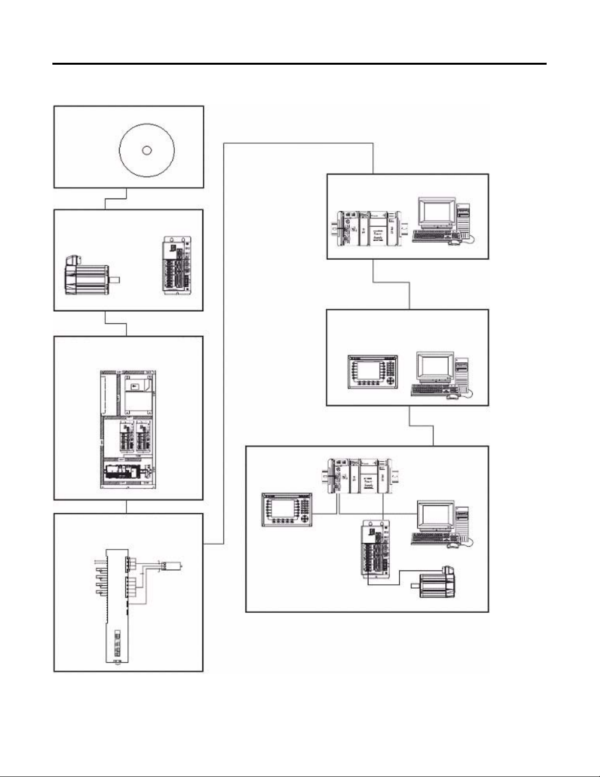
Where to Start
Follow the path below to complete your CompactLogix Indexing Motion application.
Chapter 1
CD Installation
Chapter 5
Motion Logix
Integration
Chapter 2
Hardware Selection
Chapter 6
Motion FactoryTalk View Integration
Chapter 3
Plan System Layout
Chapter 4
Plan System Wiring
Chapter 7
Motion System
Application Guide
Publication IASIMP-QS011B-EN-P — January 2009 3
Page 4

Where to Start
Notes:
4 Publication IASIMP-QS011B-EN-P — January 2009
Page 5

CD Installation
Hardware Selection
Table of Contents
Preface
Introduction . . . . . . . . . . . . . . . . . . . . . . . . . . . . . . . . . . . . 9
Required Software . . . . . . . . . . . . . . . . . . . . . . . . . . . . . . . . 10
Conventions Used in This Manual . . . . . . . . . . . . . . . . . . . . 10
Additional Resources . . . . . . . . . . . . . . . . . . . . . . . . . . . . . . 11
Chapter 1
What You Need. . . . . . . . . . . . . . . . . . . . . . . . . . . . . . . . . . 13
Follow These Steps . . . . . . . . . . . . . . . . . . . . . . . . . . . . . . . 13
Install the Kinetix Accelerator Toolkit Program . . . . . . . . . . . 14
Open the Kinetix Accelerator Toolkit Program . . . . . . . . . . . 14
Chapter 2
Before You Begin . . . . . . . . . . . . . . . . . . . . . . . . . . . . . . . . 17
What You Need. . . . . . . . . . . . . . . . . . . . . . . . . . . . . . . . . . 17
Follow These Steps . . . . . . . . . . . . . . . . . . . . . . . . . . . . . . . 18
Installing Motion Analyzer Software . . . . . . . . . . . . . . . . . . . 19
Review Basic Panel Component Listings . . . . . . . . . . . . . . . . 23
Verify Base System Performance Specifications . . . . . . . . . . . 26
Select Add-In Components. . . . . . . . . . . . . . . . . . . . . . . . . . 28
Plan System Layout
Plan System Wiring
Motion Logix Integration
Chapter 3
Before You Begin . . . . . . . . . . . . . . . . . . . . . . . . . . . . . . . . 29
What You Need. . . . . . . . . . . . . . . . . . . . . . . . . . . . . . . . . . 29
Follow These Steps . . . . . . . . . . . . . . . . . . . . . . . . . . . . . . . 30
Load Basic System CAD Drawings . . . . . . . . . . . . . . . . . . . . 31
Verify Your Basic Panel Layout . . . . . . . . . . . . . . . . . . . . . . 32
Modifying Your Motion Panel Layout . . . . . . . . . . . . . . . . . . 33
Downloading Other Allen-Bradley CAD Drawings. . . . . . . . . 34
Chapter 4
Before You Begin . . . . . . . . . . . . . . . . . . . . . . . . . . . . . . . . 35
What You Need. . . . . . . . . . . . . . . . . . . . . . . . . . . . . . . . . . 35
Follow These Steps . . . . . . . . . . . . . . . . . . . . . . . . . . . . . . . 36
Load Basic System CAD Diagrams . . . . . . . . . . . . . . . . . . . . 37
Route Cables for Your Motion Panel. . . . . . . . . . . . . . . . . . . 39
Lay Out DeviceNet and Ethernet Cables . . . . . . . . . . . . . . . . 40
Chapter 5
Before You Begin . . . . . . . . . . . . . . . . . . . . . . . . . . . . . . . . 41
What You Need. . . . . . . . . . . . . . . . . . . . . . . . . . . . . . . . . . 41
Follow These Steps . . . . . . . . . . . . . . . . . . . . . . . . . . . . . . . 42
Configure Your Servo Drives . . . . . . . . . . . . . . . . . . . . . . . . 43
Configure Your Logix DeviceNet Module . . . . . . . . . . . . . . . 46
Select Your Logix Application File . . . . . . . . . . . . . . . . . . . . 52
Publication IASIMP-QS011B-EN-P — January 2009 5
Page 6

Table of Contents
Motion FactoryTalk View
Integration
Load and Open Logix Application File . . . . . . . . . . . . . . . . 52
Configure Your Logix System . . . . . . . . . . . . . . . . . . . . . . . 53
Using the DeviceNet Tag Generator . . . . . . . . . . . . . . . . . . 55
Configure Axis Properties . . . . . . . . . . . . . . . . . . . . . . . . . . 59
Configure Logix Communications . . . . . . . . . . . . . . . . . . . . 61
Save and Download Your Program . . . . . . . . . . . . . . . . . . . 62
Chapter 6
Before You Begin . . . . . . . . . . . . . . . . . . . . . . . . . . . . . . . 65
What You Need . . . . . . . . . . . . . . . . . . . . . . . . . . . . . . . . . 65
Follow These Steps . . . . . . . . . . . . . . . . . . . . . . . . . . . . . . 66
Select Your FactoryTalk View ME Application File. . . . . . . . 67
Load and Restore the FactoryTalk View ME Application. . . . 67
Configure Local Communications . . . . . . . . . . . . . . . . . . . . 69
Configure Target Communications . . . . . . . . . . . . . . . . . . . 71
Adding Axes to the Project . . . . . . . . . . . . . . . . . . . . . . . . . 72
Modifying Axis Names . . . . . . . . . . . . . . . . . . . . . . . . . . . . 77
Test the Project . . . . . . . . . . . . . . . . . . . . . . . . . . . . . . . . . 79
Download Fonts to the Terminal . . . . . . . . . . . . . . . . . . . . 80
Download the Project to a Terminal . . . . . . . . . . . . . . . . . . 81
Run the Project on a Terminal . . . . . . . . . . . . . . . . . . . . . . 83
Motion System Application Guide
CompactLogix Base Program
Overview
Chapter 7
Before You Begin . . . . . . . . . . . . . . . . . . . . . . . . . . . . . . . 85
What You Need . . . . . . . . . . . . . . . . . . . . . . . . . . . . . . . . . 85
Follow These Steps . . . . . . . . . . . . . . . . . . . . . . . . . . . . . . 86
Startup Display . . . . . . . . . . . . . . . . . . . . . . . . . . . . . . . . . 87
Use the Manual Control Display . . . . . . . . . . . . . . . . . . . . . 88
Use the Auto Control Display . . . . . . . . . . . . . . . . . . . . . . . 89
Use the Trend Display . . . . . . . . . . . . . . . . . . . . . . . . . . . . 91
Use the Axis Status Display. . . . . . . . . . . . . . . . . . . . . . . . . 92
Use the Fault Log Display. . . . . . . . . . . . . . . . . . . . . . . . . . 93
Use the Security Display. . . . . . . . . . . . . . . . . . . . . . . . . . . 94
Shut Down Application . . . . . . . . . . . . . . . . . . . . . . . . . . . 94
Appendix A
Basic Program Flow . . . . . . . . . . . . . . . . . . . . . . . . . . . . . . 95
Main Machine Control (P00_Control) . . . . . . . . . . . . . . . . . 96
Axis/Equipment Control . . . . . . . . . . . . . . . . . . . . . . . . . . . 100
Add Your Application Code . . . . . . . . . . . . . . . . . . . . . . . . 101
User-defined Data Types . . . . . . . . . . . . . . . . . . . . . . . . . . 103
Add-On Instructions. . . . . . . . . . . . . . . . . . . . . . . . . . . . . . 104
PhaseManager . . . . . . . . . . . . . . . . . . . . . . . . . . . . . . . . . . 105
6 Publication IASIMP-QS011B-EN-P — January 2009
Page 7

PhaseManager for S-88 Users
Troubleshooting
Table of Contents
Appendix B
Making Changes to the Program Template . . . . . . . . . . . . . 107
Making Changes to Operator Interface Screens . . . . . . . . . . 112
Appendix C
Troubleshooting the Manual Cycle . . . . . . . . . . . . . . . . . . . 115
Troubleshooting the Automatic Cycle . . . . . . . . . . . . . . . . . 122
Publication IASIMP-QS011B-EN-P — January 2009 7
Page 8

Table of Contents
Notes:
8 Publication IASIMP-QS011B-EN-P — January 2009
Page 9

Preface
Introduction
This quick start provides examples of using a CompactLogix controller
to connect to multiple devices (servo drives, motors, and HMI) over
the Ethernet/IP network in a CompactLogix Indexing Motion
application. These examples were designed to get devices installed
and communicating with each other in the simplest way possible. The
programming involved is not complex, and offers easy solutions to
verify that devices are communicating properly.
To assist in the design and installation of your CompactLogix Indexing
Motion system, application files and other information are provided
on the Kinetix Accelerator Toolkit CD, publication IASIMP-SP004. The
CD provides CAD drawings for panel layout and wiring, base Logix
control programs, FactoryTalk View (HMI) application files, and more.
For a copy of the CD, contact your local Rockwell Automation
distributor or sales representative. With these tools and the built-in
best-practices design, the system designer is free to focus on the
design of machine control and not on design overhead tasks.
To download the program files, CAD files, and other selected
CompactLogix Indexing Motion Accelerator Toolkit information, refer
to the Rockwell Automation Integrated Architecture Tools website,
http://www.ab.com/go/iatools.
IMPORTANT
The beginning of each chapter contains the following information.
Read these sections carefully before beginning work in each chapter.
• Before You Begin - This section lists the steps that must be
completed and decisions that must be made before starting that
chapter. The chapters in this quick start do not have to be
completed in the order in which they appear, but this section
defines the minimum amount of preparation required before
completing the current chapter.
• What You Need - This section lists the tools that are required to
complete the steps in the current chapter. This includes, but is not
limited to, hardware and software.
• Follow These Steps - This illustrates the steps in the current
chapter and identifies which steps are required to complete the
examples using specific networks.
Before using this quick start and the contents of the Kinetix
Accelerator Toolkit CD, read the Terms and Conditions READ
ME.pdf on the CD.
Publication IASIMP-QS011B-EN-P — January 2009 9
Page 10

Preface
Required Software
Conventions Used in This Manual
To complete this quick start, the following software is required.
Rockwell Automation Software Cat. No. Minimum
Version
RSLogix 5000 Mini Edition 9324-RLD200ENE 17
FactoryTalk View Studio for Machine Edition
(Includes RSLinx Enterprise and
RSLinx Classic)
Ultraware Drive Configuration Software for
the Ultra3000/5000
RSNetWorx for DeviceNet 9357-DNETL3 8.00.02
RSLogix 5000 DeviceNet Tag Generator Tool Provided on Toolkit CD Build 87
Motion Analyzer/Motion Selector CD
Kinetix Accelerator Toolkit CD IASIMP-SP004
9701-VWSTMENE 5.00
2098-UWCPRG 1.64
Download from
http://ab.com/e-tools
4.x
⎯
This manual uses the following conventions.
Convention Meaning Example
click
double-click
right-click
drag and drop
Select Click to highlight a specific option. Select H1-1 from the list.
check/uncheck Click to activate/deactivate a checkbox.
>
expand Click the + to the left of a given item/folder to show its contents. In the H1-1 window, expand the FFLD.
Click left mouse button once (assumes cursor is positioned on
object or selection). Click button to initiate action.
Click left mouse button twice in quick succession. (Assumes
cursor is positioned on object or selection.)
Click right mouse button once. (Assumes cursor is positioned on
object or selection.)
Click and hold the left mouse button on an object, move the
cursor to where you want to move the object, and release the
mouse button.
Shows nested menu selections as menu name followed by menu
choice.
Click Browse.
Double-click the H1 icon.
Right-click the Fieldbus Networks icon.
Drag and drop the desired block into the Strategy
window.
Check the Do not show this dialog again
checkbox.
Choose Programs>Rockwell Automation
>Simplification>Kinetix Accelerator Toolkit.
Note: The path sequences given in this
manual are for a typical system installation.
If your system was installed in a different
directory, use the appropriate path.
10 Publication IASIMP-QS011B-EN-P — January 2009
Page 11

Additional Resources
Resource Description
http://www.ab.com Provides access to the Allen-Bradley website.
http://rockwellautomation.com/knowledgebase Provides access to self-service support.
http://www.rockwellautomation.com/components/connected Provides access to the Connected Components website.
Preface
Publication IASIMP-QS011B-EN-P — January 2009 11
Page 12

Preface
Notes:
12 Publication IASIMP-QS011B-EN-P — January 2009
Page 13

Chapter
1
CD Installation
In this chapter, you install the Kinetix Accelerator Toolkit program CD to your personal computer.
All of the necessary files are transferred to the personal computer for ease of use.
What You Need
• The Kinetix Accelerator Toolkit CD, publication IASIMP-SP004
• Personal computer with:
– an Intel Pentium II or greater microprocessor
– 128 MB of RAM for Windows NT, Windows 2000, Windows 2003, Windows 2003 R2, or
Windows XP (64 MB for Windows 98) operating systems
– 300 MB of available hard-disk space
Follow These Steps
Complete the following steps to install the Kinetix Accelerator Toolkit program.
Start
Install the Kinetix
Accelerator Toolkit Program
page 14
Open the Kinetix
Accelerator Toolkit Program
page 14
Publication IASIMP-QS011B-EN-P — January 2009 13
Page 14
Chapter 1 CD Installation
Install the Kinetix Accelerator Toolkit Program
Follow these steps to download and install the Kinetix Accelerator Toolkit program from the CD.
1. Place the Kinetix Accelerator Toolkit CD, publication IASIMP-SP004, in your CD tray.
2. The installation program should run automatically. If not, browse to the CD and run the file
Setup.exe.
3. Follow the on-screen instructions to complete the program installation.
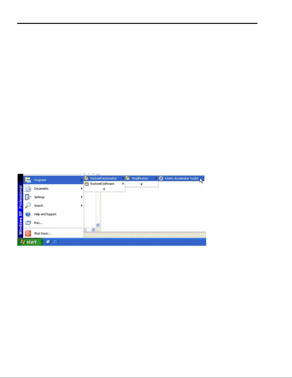
Open the Kinetix Accelerator Toolkit Program
Follow these steps to begin using the Kinetix Accelerator Toolkit program.
From the Start menu, choose Programs>Rockwell Automation>Simplification>Kinetix Accelerator
Toolkit.
14 Publication IASIMP-QS011B-EN-P — January 2009
Page 15

The Kinetix Accelerator Toolkit program starts.
CD Installation Chapter 1
Follow the steps in the remaining chapters of this manual to complete your system configuration.
Publication IASIMP-QS011B-EN-P — January 2009 15
Page 16

Chapter 1 CD Installation
Notes:
16 Publication IASIMP-QS011B-EN-P — January 2009
Page 17

Chapter
2
Hardware Selection
In this chapter, you make your motion application hardware selection. You can select from the
basic motion control panels, or use Motion Analyzer software to size your servo drive and motor.
The basic motion control panels can be modified with up to four axes, a different PanelView Plus
terminal, and other optional equipment.
Before You Begin
• Determine your base motion system input voltage.
– 400/460V
– 200/230V
• Verify that your computer meets the software requirements of Motion Analyzer software,
version 4.x.
• Complete the Kinetix Accelerator Toolkit CD installation (Refer to Chapter 1).
What You Need
• Kinetix Accelerator Toolkit CD, publication IASIMP-SP004. For a copy of the CD, contact your
local Rockwell Automation distributor or sales representative.
• Personal computer with Internet access for downloading software.
• Motion Analyzer software, version 4.x is available from:
– the Kinetix Accelerator Toolkit CD, publication IASIMP-SP004
– http://ab.com/e-tools
• Kinetix Motion Control Selection Guide, publication GMC-SG001.
Publication IASIMP-QS011B-EN-P — January 2009 17
Page 18
Chapter 2 Hardware Selection
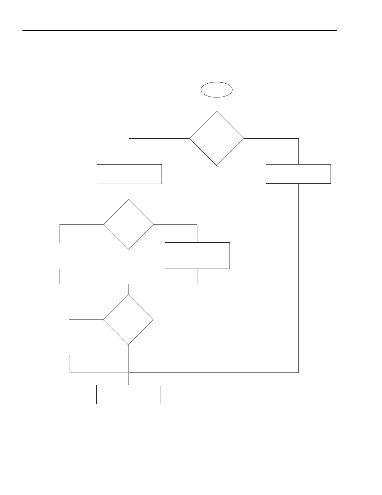
Follow These Steps
Complete the following steps to select your motion system hardware.
Start
Verify Base System
Performance
Specifications (230V)
page 26
Review Basic Panel
Component Listings
page 23
230V 460V
230V or
460V input
voltage?
Yes No
Verify Base System
Performance
Specifications (460V)
Start with
Basic Motion Control
Panels?
page 26
Installing Motion
Analyzer Software
page 19
Yes
Installing Motion
Analyzer Software
page 19
18 Publication IASIMP-QS011B-EN-P — January 2009
Further verify
or change motion
selections?
No
Select Add-In
Components
page 28
Page 19
Hardware Selection Chapter 2
Installing Motion Analyzer Software
Motion Analyzer software is a comprehensive motion control tool with application analysis
software used for sizing your application. You can download and install Motion Analyzer
software from the Web, or install Motion Analyzer software from the Kinetix Accelerator Toolkit
CD, publication IASIMP-SP004.
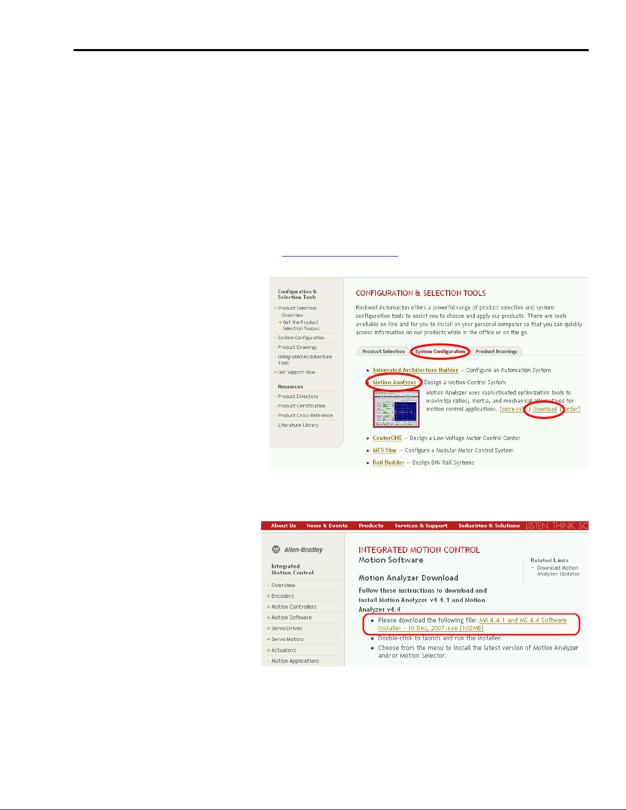
Download Motion Analyzer Software From the Web
Follow these steps to download and install Motion Analyzer software.
1. Open your Web browser and go to http://ab.com/e-tools.
The Configuration and
Selection Tools webpage
opens.
2. Select Motion Analyzer from
the System Configuration tab.
3. Click Download.
The Motion Analyzer webpage opens.
4. Click the Motion Analyzer
software download link and
follow the instructions
provided.
5. Use Motion Analyzer software
to size your motor/drive
combinations.
Publication IASIMP-QS011B-EN-P — January 2009 19
Page 20
Chapter 2 Hardware Selection
Install Motion Analyzer Software from the Kinetix Accelerator Toolkit CD
Follow these steps to install Motion Analyzer software from the CD.
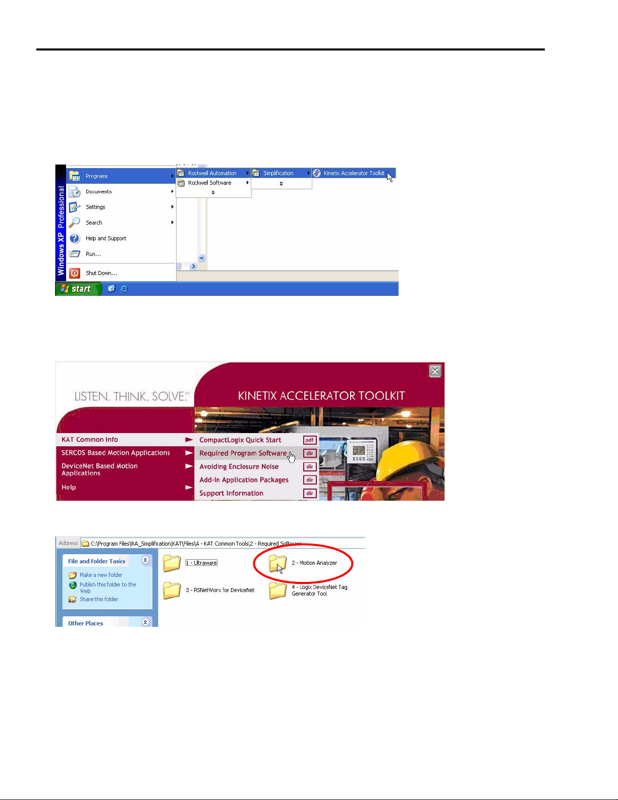
1. From the Start menu, choose Programs>Rockwell Automation>Simplification>Kinetix
Accelerator Toolkit.
The Kinetix Accelerator Toolkit program starts.
2. From the toolkit menu, choose KAT Common Info>Required Program Software.
3. Open the 2 - Motion Analyzer folder.
20 Publication IASIMP-QS011B-EN-P — January 2009
Page 21
Hardware Selection Chapter 2
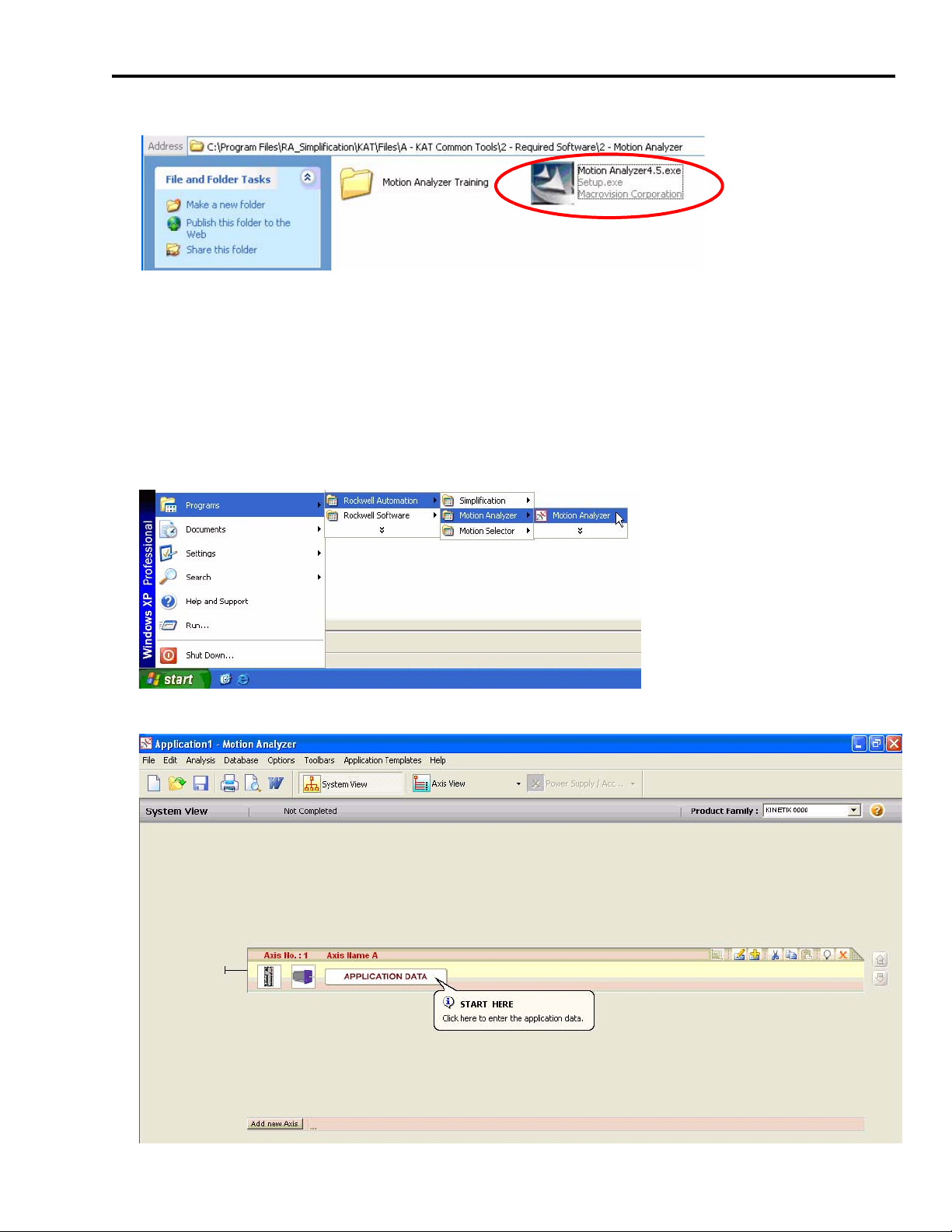
4. Double-click MotionAnalyzer 4.x.exe.
5. Follow the on-screen instructions to complete the program installation.
Open Motion Analyzer Software
Follow these steps to run the Motion Analyzer software.
1. From the Start menu, choose Programs>Rockwell Automation>Motion Analyzer>Motion
Analyzer.
The starting selection window opens.
Publication IASIMP-QS011B-EN-P — January 2009 21
Page 22
Chapter 2 Hardware Selection
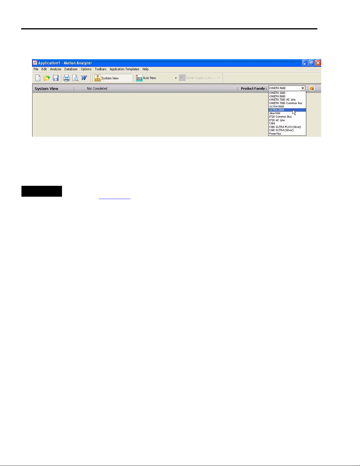
2. Use the Product Family drop-down menu to select Ultra3000. (Kinetix 6000 is the default
selection.)
3. Click Application Data.
4. Complete the system profile for your application.
TIP
For motor/drive performance specifications, refer to the Kinetix Motion Control Selection Guide,
publication GMC-SG001.
For Motion Analyzer labs, refer to the Motion Analyzer Training Folder on the Kinetix Accelerator
Toolkit CD, publication IASIMP-SP004. For a copy of the CD, contact your local Rockwell
Automation distributor or sales representative.
22 Publication IASIMP-QS011B-EN-P — January 2009
Page 23

Hardware Selection Chapter 2
Review Basic Panel Component Listings
The tables in this section include servo drives and motors, CompactLogix controller, PanelView
Plus terminal (HMI), and accessory components for 400/460V and 200/230V systems. Review the
basic component listings and compare with your specific application needs.
CompactLogix L31, 400/460V Base System
# Used Components Cat. No. Description
1 Enclosure and panel (HxWxD, approx.)
1
Input power
1 140U-H-RVM12R Through-the-door disconnect
1 Line Filter 2090-XXLF-X330B 3-phase, 30 A AC line filter
Ultra3000 Servo
3
Drive System
Line Interface Module (LIM)
Servo Drive 2098-DSD-HV030X-DN
Hoffman
Rittal
2094-BL50S 460V, 50 A LIM module
1524 x 914 x 304 mm
(60 x 36 x 12 in.)
3 kW output, indexing, DeviceNet communication
option
3 Motors MP-Series Low Inertia MPL-B310P-MK22AA 0.77 kW output with absolute, multi-turn feedback
3
3 Motor Feedback 2090-XXNFMP-S03 3 m (9.8 ft), MPL-B310P
Cables
1 HMI Communication 2711-NC13 5 m (16 ft), 9-pin to 9-pin
1 DeviceNet Media 1485C-P1A50 Trunk cable, round 50 m spool
3 Connector kit Feedback 2090-UXBB-DM15 Connector kit for motor feedback
3 Connector kit Control I/O 2090-U3BB2-DM44 Connector kit for control I/O signals
1 HMI PanelView Plus 2711P-T6C5D PanelView Plus 600, 24V DC, serial comms
1
1 1769-IQ16 16-point 24V DC input module
1 1769-OB16 16-point 24V DC sourcing output module
Logix controller
1 1769-PB2 Power supply, 24V DC
1 1769-SDN DeviceNet interface module
1 1769-ECR End cap
1
Software
1 HMI Programming 9701-VWSTMENE FactoryTalk View Studio Machine Edition
1 Drive Configuration 2098-UWCPRG Ultraware Software
Motor Power 2090-XXNPMP-16S03 3 m (9.8 ft), MPL-B310P
1769-L31 Controller, dual-serial comms, 512k memory
CompactLogix with Serial
Configuration
Controller Programming 9324-RLD200ENE RSLogix 5000 Mini Edition
Publication IASIMP-QS011B-EN-P — January 2009 23
Page 24

Chapter 2 Hardware Selection
CompactLogix L31, 200/230V Base System
# Used Components Cat. No. Description
1 Enclosure and panel (HxWxD, approx.)
1
Input power
1 140U-H-RVM12R Through-the-door disconnect
1 Line Filter 2090-XXLF-X330B 3-phase, 30 A AC line filter
Ultra3000 Servo
3
Drive
3 Motors MP-Series Low Inertia MPL-A310P-MK22AA
3
3 Motor Feedback 2090-XXNFMP-S03 3 m (9.8 ft), MPL-A310P
Cables
1 HMI Communication 2711-NC13 5 m (16 ft), 9-pin to 9-pin
1 DeviceNet Media 1485C-P1A50 Trunk cable, round 50 m spool
3 Connector kit Feedback 2090-UXBB-DM15 Connector kit for motor feedback
3 Connector kit Control I/O 2090-U3BB2-DM44 Connector kit for control I/O signals
1 HMI PanelView Plus 2711P-T6C5D PanelView Plus 600, 24V DC, serial comms
1
1 1769-IQ16 16-point 24V DC input module
Line Interface Module (LIM)
Servo Drive 2098-DSD-010X-DN
Motor Power 2090-XXNPMP-16S03 3 m (9.8 ft), MPL-A310P
Hoffman
Rittal
2094-AL50S 230V, 50 A LIM module
1769-L31 Controller, dual-serial comms, 512k memory
1219 x 609 x 304 mm
(48 x 24 x 12 in.)
1 kW output, indexing, DeviceNet
communication option
0.73 kW output with absolute, multi-turn
feedback
1 1769-OB16 16-point 24V DC sourcing output module
Logix controller
1 1769-PB2 Power supply, 24V DC
1 1769-SDN DeviceNet interface module
1 1769-ECR End cap
1
Software
1 HMI Programming 9701-VWSTMENE FactoryTalk View Studio Machine Edition
1 Drive Configuration 2098-UWCPRG Ultraware Software
CompactLogix with Serial
Configuration
Controller Programming 9324-RLD200ENE RSLogix 5000 Mini Edition
24 Publication IASIMP-QS011B-EN-P — January 2009
Page 25

CompactLogix L23E, 200/230V Base System
# Used Components Cat. No. Description
Hardware Selection Chapter 2
1 Enclosure and panel (HxWxD, approx.)
1
Input power
1 140U-H-RVM12R Through-the-door disconnect
1 Line Filter 2090-XXLF-X330B 3-phase, 30 A AC line filter
Ultra3000 Servo
1
Drive
1 Motors MP-Series Low Inertia MPL-A310P-MK22AA
1
1 Motor Feedback 2090-XXNFMP-S03 3 m (9.8 ft), MPL-A310P
Cables
1 HMI Communication 2711P-CBL-EX04 4 m (14 ft), Ethernet crossover
1 DeviceNet Media 1485C-P1A50 Trunk cable, round 50 m, spool
1 Connector kit Feedback 2090-UXBB-DM15 Connector kit for motor feedback
1 Connector kit Control I/O 2090-U3BB2-DM44 Connector kit for control I/O signals
1 HMI PanelView Plus 2711P-T6C20D PanelView Plus 600, 24V DC, Ethernet comms
1
Logix controller
1 1769-SDN DeviceNet interface module
1
Line Interface Module (LIM)
Servo Drive 2098-DSD-010X-DN
Motor Power 2090-XXNPMP-16S03 3 m (9.8 ft), MPL-A310P
CompactLogix with Serial
Configuration
Controller Programming 9324-RLD200ENE RSLogix 5000 Mini Edition
Hoffman
Rittal
2094-AL50S 230V, 50 A LIM module
1769-L23E-QB1B
1219 x 609 x 304 mm
(48 x 24 x 12 in)
1 kW output, indexing, DeviceNet
communication option
0.73 kW output with absolute, multi-turn
feedback
Controller, serial and Ethernet/IP comms, 512k
memory, 16 DC in, 16 DC out, 24V DC power
supply
Software
1 HMI Programming 9701-VWSTMENE FactoryTalk View Studio Machine Edition
1 Drive Configuration 2098-UWCPRG Ultraware Software
Publication IASIMP-QS011B-EN-P — January 2009 25
Page 26

Chapter 2 Hardware Selection
Verify Base System Performance Specifications
This section provides system combination information for the Ultra3000 drives when matched
with MP-Series low-inertia motors. Included are motor power, feedback, and brake cable catalog
numbers, system performance specifications, and torque/speed curves. Refer to the Kinetix
Motion Control Selection Guide, publication GMC-SG001, for additional motor/drive performance
specifications.
Refer to the following table to determine the appropriate cables needed for your Ultra3000 drive
and motor combination.
Ultra3000 Servo Drive Motor Type Motor Power Cable Motor Feedback Cable Motor Brake Cable
2098-DSD-HV030X-DN MPL-B310P
2098-DSD-010X-DN MPL-A310P
(1)
Use connector kit (catalog number 2090-UXBB-D15M) or panel-mounted breakout components on drive end. Refer to the Kinetix Motion Control Selection Guide,
publication GMC-SG001, for catalog numbers.
(2)
Premolded (drive end) feedback cables (catalog number 2090-UXNFBMP-Sxx) are also available for Ultra3000 drives.
Motor end connector kits are available for motor power, feedback, and brake cables. Refer to the Kinetix Motion Control Selection Guide, publication GMC-SG001
numbers.ttt Cable length xx is in meters.
2090-XXNPMF-16Sxx
2090-XXNFMF-Sxx
Absolute High-resolution
Feedback
(1) (2)
2090-UXNBMP-18Sxx
, for catalog
400/460V System Performance Specifications
Motor
MPL-B310P 5000 2.4 1.58 (14) 7.1 3.61 (32) 0.72 2098-DSD-HV030X-DN
Max
Speed
rpm
System
Continuous
Stall Current
A 0-pk
System
Continuous
Stall Torque
N•m (in•lb)
System Peak
Stall Current
A 0-pk
System Peak
Stall Torque
N•m (in•lb)
Motor
Rated
Output
kW
Ultra3000 460V Drives
200/230V System Performance Specifications
Motor
MPL-A310P 5000 4.85 1.58 (14) 14 3.61 (32) 0.73 2098-DSD-010X-DN
Max
Speed
rpm
System
Continuous
Stall Current
A 0-pk
System
Continuous
Stall Torque
N•m (in•lb)
System Peak
Stall Current
A 0-pk
System Peak
Stall Torque
N•m (in•lb)
Motor
Rated
Output
kW
Ultra3000 230V Drives
26 Publication IASIMP-QS011B-EN-P — January 2009
Page 27
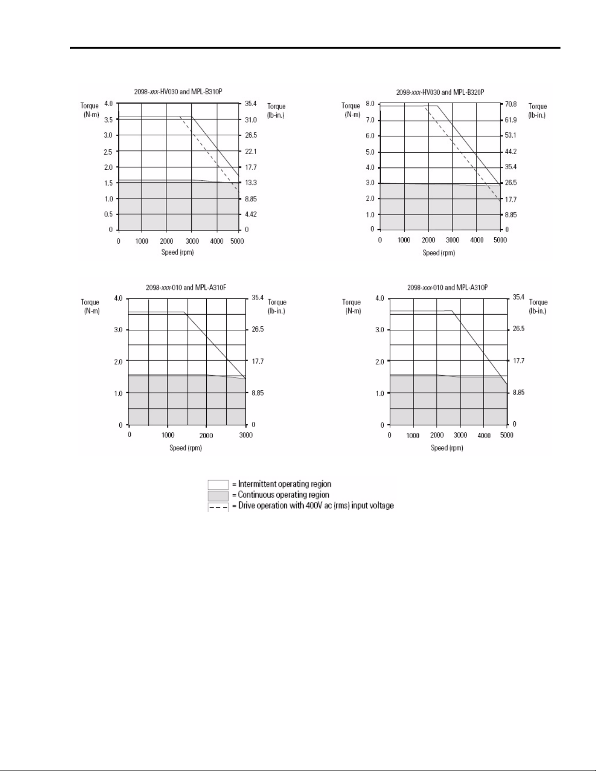
Ultra3000 Drives/MP-Series Low Inertia Motor Curves
Hardware Selection Chapter 2
Publication IASIMP-QS011B-EN-P — January 2009 27
Page 28
Chapter 2 Hardware Selection
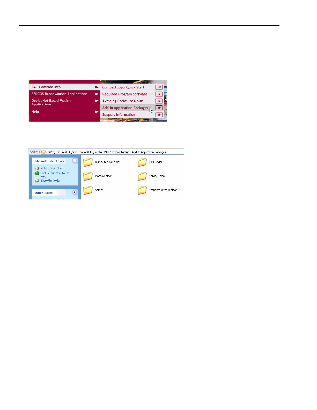
Select Add-In Components
Follow these steps to add components to your base system.
1. From the toolkit menu, choose KAT Common Info>Add-In Application Packages.
2. Identify additional components listed in the Add-In Application Packages folder that you
would like to add to your system.
3. If necessary, identify additional components not listed in the Add-In Application Packages
folder. Contact your local Allen-Bradley representative for more information.
28 Publication IASIMP-QS011B-EN-P — January 2009
Page 29

Chapter
3
Plan System Layout
In this chapter, you layout the system components selected in Chapter 2. Use the CAD drawings
supplied on the Kinetix Accelerator Toolkit CD, publication IASIMP-SP004, to add or remove
components to and from the basic motion control panel system. For a copy of the CD, contact
your local Rockwell Automation distributor or sales representative.
Before You Begin
• Complete the Kinetix Accelerator Toolkit CD installation. (Refer to Chapter 1.)
• Complete your system hardware selection. (Refer to Chapter 2.)
What You Need
• Kinetix Accelerator Toolkit CD, publication IASIMP-SP004
• System Design for Control of Electrical Noise Reference Manual, publication GMC-RM001
• System Design for Control of Electrical Noise Video, publication GMC-SP004
• Ultra3000 Digital Servo Drive Installation Manual, publication 2098-IN003
• Ultra3000 Digital Servo Drive with DeviceNet Reference Manual, publication 2098-RM004
Publication IASIMP-QS011B-EN-P — January 2009 29
Page 30
Chapter 3 Plan System Layout
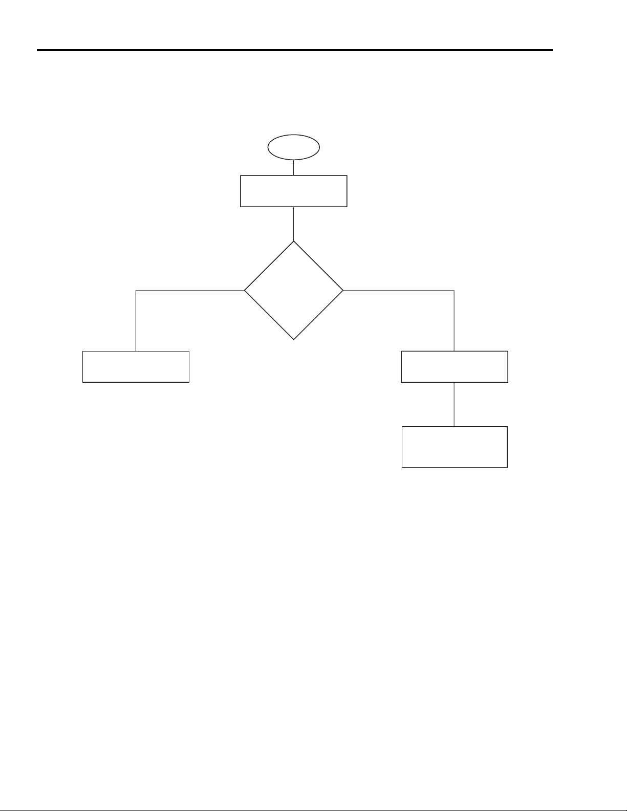
Follow These Steps
Complete the following steps to plan your system layout within the enclosure.
Start
Load Basic System
CAD Drawings
page 31
Verify Your Basic Panel
Layout
page 32
Yes
Use
Basic Motion Control
Panel as is?
No
Modifying Your
Motion Panel Layout
page 33
Downloading Other
Allen-Bradley CAD
Drawings
page 34
30 Publication IASIMP-QS011B-EN-P — January 2009
Page 31
Plan System Layout Chapter 3
Load Basic System CAD Drawings
The Kinetix Accelerator Toolkit CD provides CAD drawings, in DXF format, to assist in planning
the layout of your system. The drawings are designed to optimize panel space and to minimize
electrical noise.
Follow these steps to locate the CAD files from the Kinetix Accelerator Toolkit CD.
1. Open the Kinetix Accelerator Toolkit program. From the Start menu, choose
Programs>Rockwell Automation>Simplification>Kinetix Accelerator Toolkit.
2. From the Toolkit menu, choose
DeviceNet Based Motion
Applications>Enclosure CAD
Files.
3. Use your CAD program to open
these and other enclosure CAD
files:
• CIMAT_L23_230_PANEL_LAYOUT.dwg
• CIMAT_L31_460_PANEL_LAYOUT.dwg
4. Identify additional layout needs specific to your application.
Publication IASIMP-QS011B-EN-P — January 2009 31
Page 32
Chapter 3 Plan System Layout
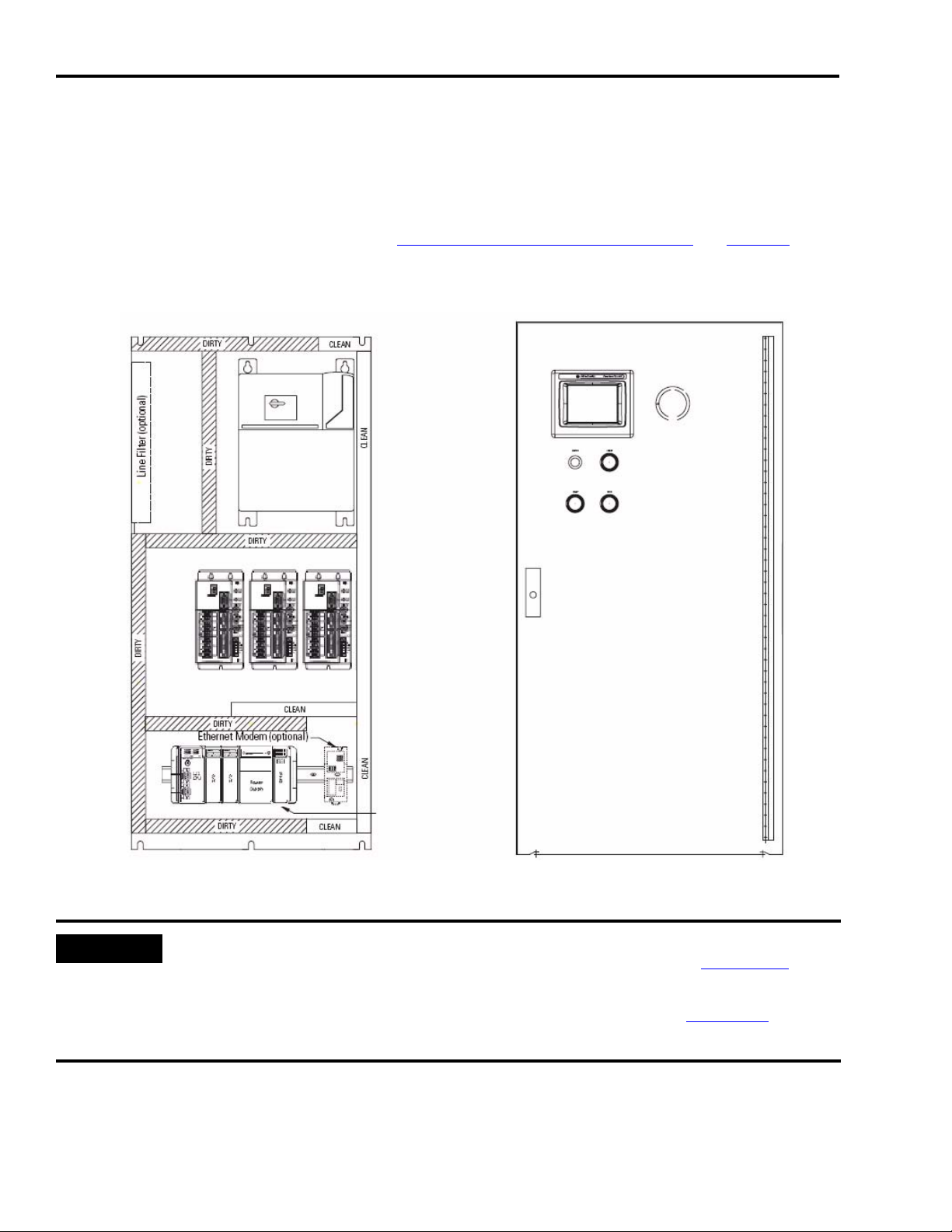
Verify Your Basic Panel Layout
The basic motion control panel layout is shown below. Included is a three-axis Ultra3000 drive
system with Line Interface Module (LIM), PanelView Plus 600 terminal, and CompactLogix
controller with DeviceNet interface module. Verify that your system matches this diagram. If it
does not match, follow the instructions in Modifying Your Motion Panel Layout on page 33.
Sample Information from Enclosure Files
PanelView Plus 600 Terminal (HMI)
Through-the-door
LIM Module
Disconnect
IMPORTANT
Bulletin 800EP
Push Buttons
Ultra3000 Indexing
Servo Drives with
DeviceNet
(230V AC shown)
CompactLogix
Controller
1769-SDN
DeviceNet Module
Optional Equipment Includes:
• Line Filter (required for CE)
• PowerFlex 40 AC Drive
• Ethernet Modem
• Point IO System
• Safety Relay
Enclosure
1219 x 609 x 304 mm
(48 x 24 x 12 in)
The enclosure CAD drawings were designed using best-practices techniques as shown in the
System Design for Control of Electrical Noise Reference Manual, publication GMC-RM001
. Refer
to this publication when making modifications to the basic motion control panel layout.
Refer to the Ultra3000 Digital Servo Drives Installation Manual, publication 2098-IN003, for panel
layout instructions specific to the Ultra3000 drives.
32 Publication IASIMP-QS011B-EN-P — January 2009
Page 33

Plan System Layout Chapter 3
Modifying Your Motion Panel Layout
Follow the steps in this section if you do not use the basic motion control panel as is and want to
modify your motion panel layout.
1. From the basic motion control panel CAD drawing, remove the equipment you do not need
for your application.
2. Open the CAD drawings of optional equipment you would like to add to your system. From
the Toolkit menu, choose KAT Common Info>Add-In Application Packages.
3. Copy and paste objects from the optional equipment CAD drawings to the basic motion
control panel drawing.
4. Select other hardware as needed.
Refer to Downloading Other Allen-Bradley CAD Drawings on page 34. Refer to the Literature
Library (http://literature.rockwellautomation.com) for access to publications.
5. Determine if your duty cycle and selected components require additional cooling.
Refer to Enclosure Selection in the Ultra3000 Digital Servo Drive Installation Manual,
publication 2098-IN003
, for an enclosure sizing example.
Publication IASIMP-QS011B-EN-P — January 2009 33
Page 34
Chapter 3 Plan System Layout
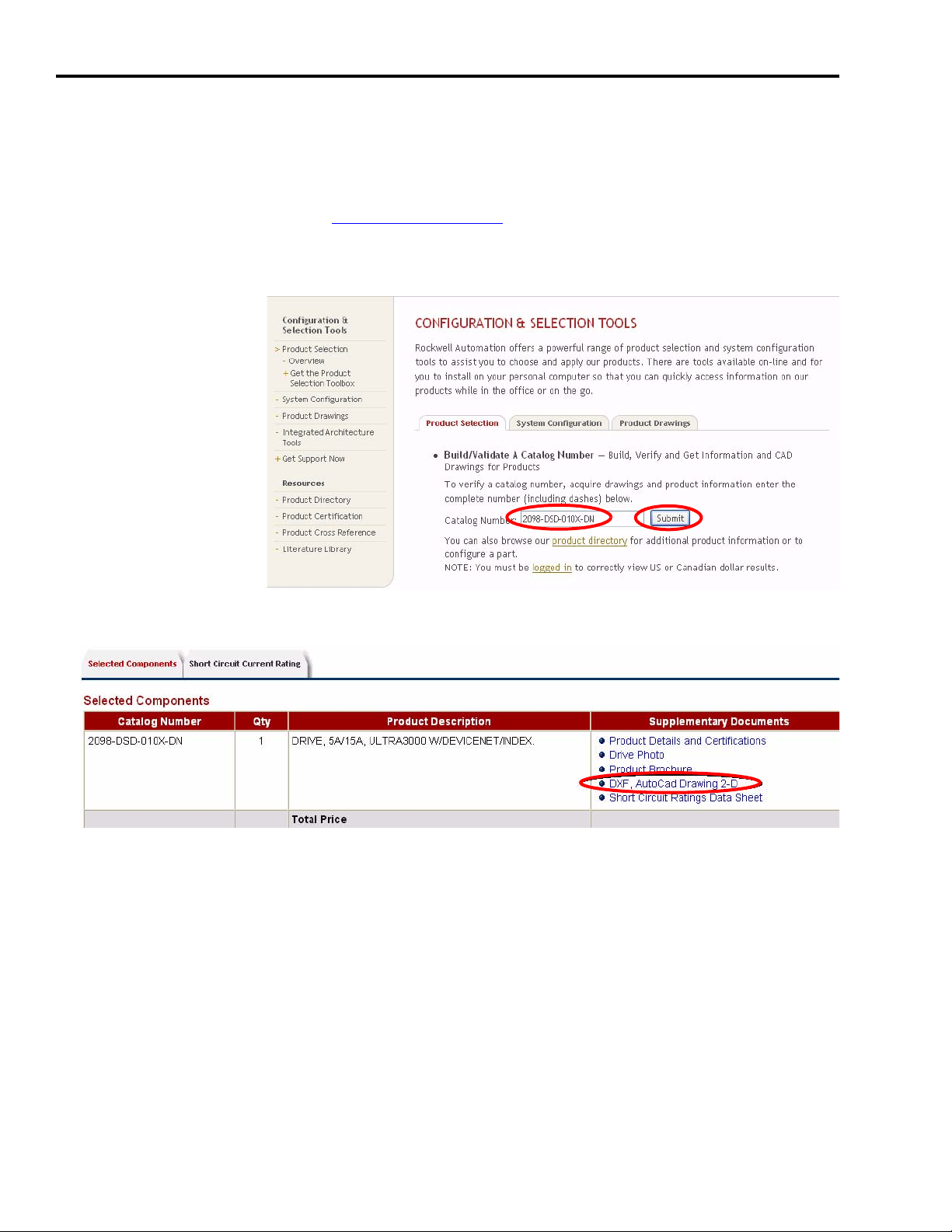
Downloading Other Allen-Bradley CAD Drawings
Follow these steps if you want to download other Allen-Bradley product CAD drawings.
1. Open your browser and go to http://ab.com/e-tools.
The Configuration and Selection Tools webpage opens.
2. Enter the Catalog
Number of the
product.
3. Click Submit.
The Configuration Results dialog opens.
4. Click DXF, AutoCad Drawing 2-D.
5. Download and save the file.
34 Publication IASIMP-QS011B-EN-P — January 2009
Page 35

Chapter
4
Plan System Wiring
In this chapter, you plan the cable layout for your system components placed in Chapter 3. Use
the CAD drawings supplied with the Kinetix Accelerator Toolkit CD to assist in the routing of
wires and cables for your system components. For a copy of the CD, contact your Rockwell
Automation distributor or sales representative.
Before You Begin
• Complete the Kinetix Accelerator Toolkit CD installation. (Refer to Chapter 1.)
• Complete your system hardware selection. (Refer to Chapter 2.)
• Complete your system layout. (Refer to Chapter 3.)
What You Need
• Kinetix Accelerator Toolkit CD, publication IASIMP-SP004
• CAD files typical of those included on the Kinetix Accelerator Toolkit CD:
CAD file name Description
CIMAT_Lxx_xxx_PANEL_LAYOUT.dwg
CIMAT_Lxx_xxx_1_POWER_DISTRIBUTION.dwg Power Distribution Connection Diagram for 230V AC or 460V AC Systems
CIMAT_Lxx_xxx _2_CONTROL_POWER.dwg 120V AC and 24V DC Power Distribution
CIMAT_Lxx_xxx _3_LIM_DISTRIBUTION.dwg Line Interface Module Connections
CIMAT_Lxx_xxx _4_DRIVE1_IO.dwg Ultra3000 I/O Connections for CN1 - Drive 1
CIMAT_Lxx_xxx _5_DRIVE2_IO.dwg Ultra3000 I/O Connections for CN1 - Drive 2
CIMAT_Lxx_xxx _6_DRIVE3_IO.dwg Ultra3000 I/O Connections for CN1 - Drive 3
CIMAT_Lxx_xxx _7_NETWORK_CONNECTIONS.dwg DeviceNet Network Communication and Power Supply Connections
CIMAT_Lxx_xxx _8_PLC_IO.dwg
CIMAT_Lxx_xxx _9_TERMINAL_DETAIL.dwg Terminal Blocks within Enclosure
CIMAT_Lxx_xxx _10_CONNECTOR_DETAIL_CN1.dwg Ultra3000 Drive I/O Connector Detail for 230V AC and 460V AC Drives
CIMAT_Lxx_xxx _11_CONNECTOR_DETAIL_CN2.dwg Ultra3000 Drive Feedback Connector Detail
Base CompactLogix System Enclosure and 230V AC or 460V AC Drive Layout
and Diagram
1769-IQ16, 16-Point, Sink/Source, 24V DC Input Wiring Diagram and
1769-OB16, 16-Point, Sourcing, 24V DC Output Wiring Diagram
Publication IASIMP-QS011B-EN-P — January 2009 35
Page 36

Chapter 4 Plan System Wiring
• Ultra3000 Digital Servo Drive Installation Manual, publication 2098-IN003
• Line Interface Module Installation Instructions, publication 2094-IN005
• System Design for Control of Electrical Noise, publication GMC-RM001
• System Design for Control of Electrical Noise Video, publication GMC-SP004
• Documentation that came with your other Allen-Bradley products
Refer to the Literature Library (http://literature.rockwellautomation.com) for access to
publications.
Follow These Steps
Complete the following steps to plan the installation and wiring of your system components
within the enclosure.
Start
Load Basic System
CAD Diagrams
page 37
Route Cables for Your
Motion Panel
page 39
Lay Out DeviceNet and
Ethernet Cables
page 40
36 Publication IASIMP-QS011B-EN-P — January 2009
Page 37

Plan System Wiring Chapter 4
Load Basic System CAD Diagrams
The Kinetix Accelerator Toolkit CD, publication IASIMP-SP004, provides CAD diagrams, in DWG
format, to assist in planning your system wiring. The diagrams are designed to optimize panel
space and to minimize electrical noise.
Follow these steps to locate the CAD files for the Kinetix Accelerator Toolkit CD.
1. Open the Kinetix Accelerator Toolkit program. From the Start menu, choose
Programs>Rockwell Automation>Simplification>Kinetix Accelerator Toolkit.
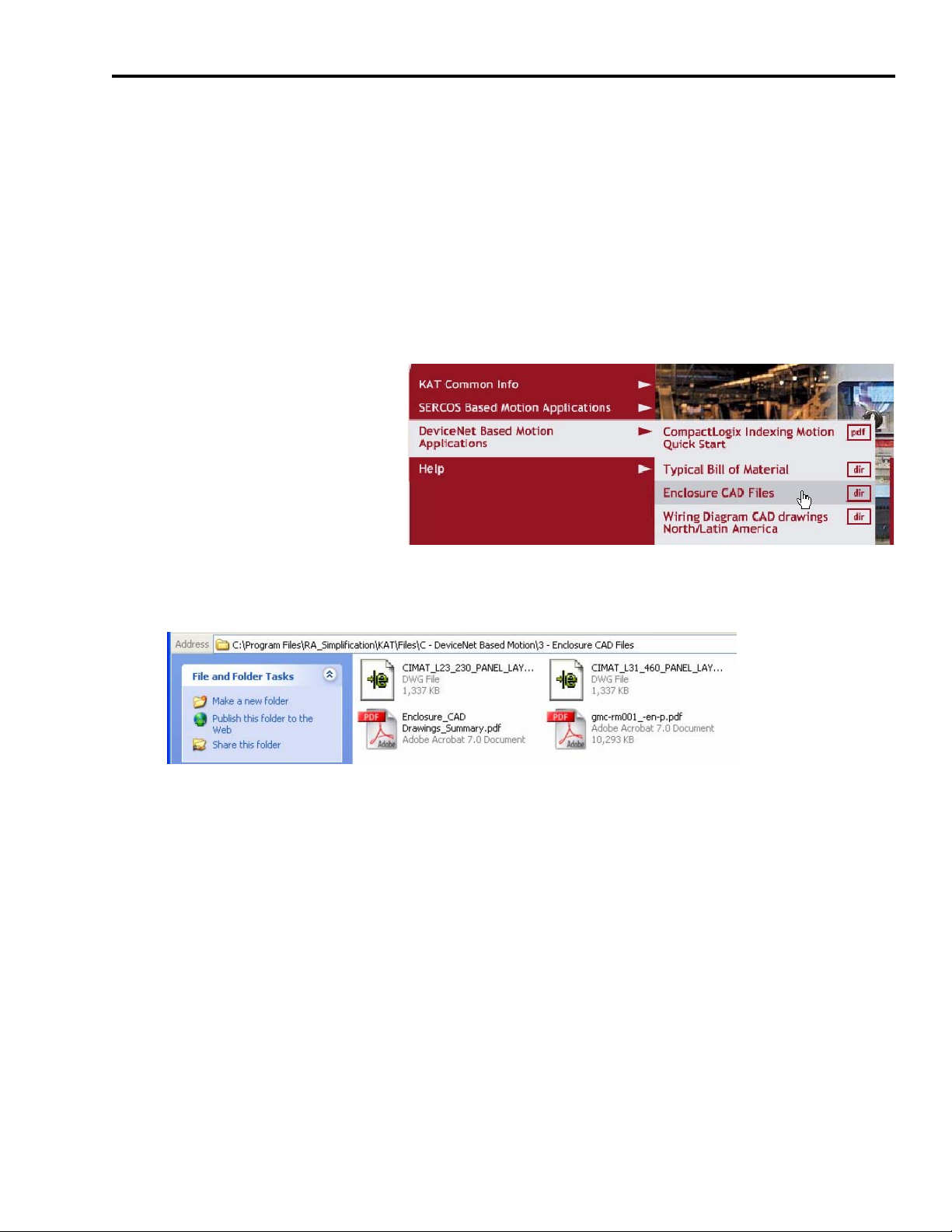
2. From the toolkit menu, choose DeviceNet Based
Motion Applications>Enclosure CAD Files.
3. Use your CAD program to open these and other
enclosure CAD files.
• CIMAT_L23_230_PANEL_LAYOUT.dwg
• CIMAT_L31_460_PANEL_LAYOUT.dwg
4. From the Toolkit menu, choose DeviceNet
Based Motion Applications>Wiring Diagram
CAD Drawings North/Latin America.
Publication IASIMP-QS011B-EN-P — January 2009 37
Page 38

Chapter 4 Plan System Wiring
5. Use your CAD program to open these and other wiring diagram CAD files.
• CIMAT_Lxx_xxx_1_POWER_DISTRIBUTION.dwg
• CIMAT_Lxx_xxx_2_CONTROL_POWER.dwg
• CIMAT_Lxx_xxx_3_LIM_DISTRIBUTION.dwg
• CIMAT_Lxx_xxx_4_DRIVE1_IO.dwg
• CIMAT_Lxx_xxx_5_DRIVE2_IO.dwg
• CIMAT_Lxx_xxx_6_DRIVE3_IO.dwg
• CIMAT_Lxx_xxx_7_NETWORK_CONNECTIONS.dwg
• CIMAT_Lxx_xxx_8_PLC_IO.dwg
• CIMAT_Lxx_xxx_9_TERMINAL_DETAIL.dwg
• CIMAT_Lxx_xxx_10_CONNECTOR_DETAIL_CN1.dwg
• CIMAT_Lxx_xxx_11_CONNECTOR_DETAIL_CN2.dwg
TIP
The term ‘CIMAT’ refers to the CompactLogix Indexing Motion Accelerator Toolkit.
6. Identify additional wiring needs specific to your application.
38 Publication IASIMP-QS011B-EN-P — January 2009
Page 39
Plan System Wiring Chapter 4
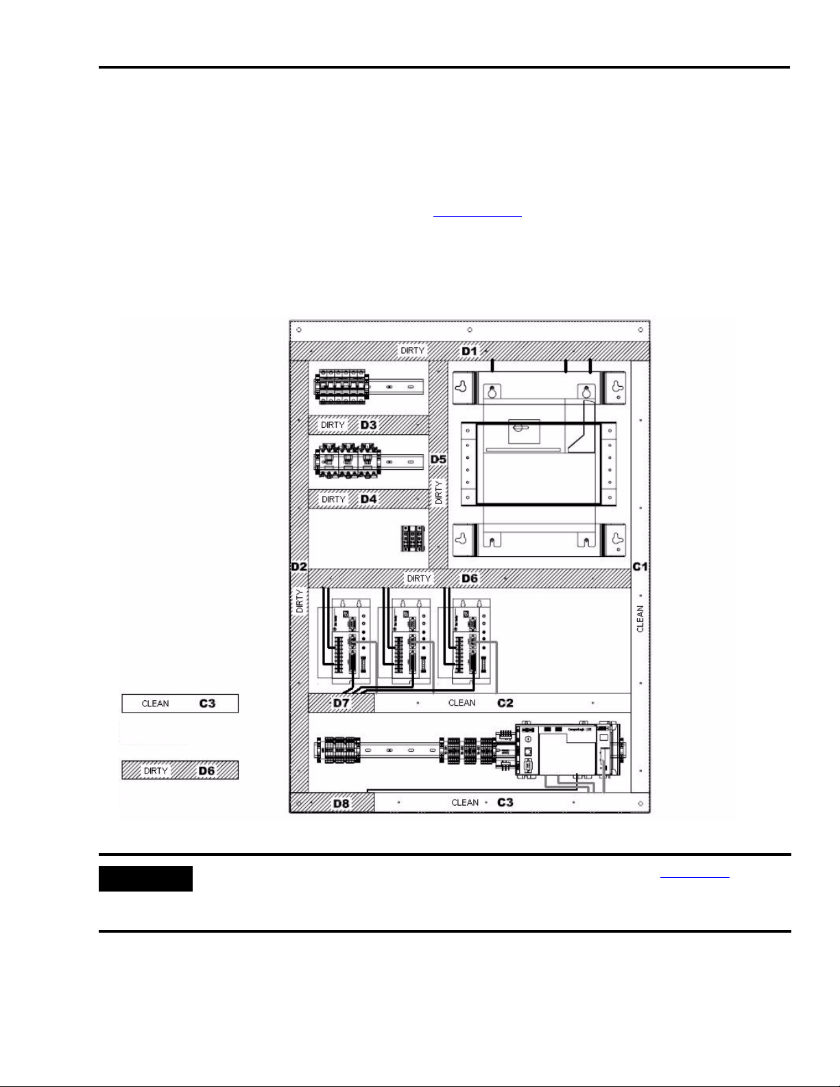
Route Cables for Your Motion Panel
The base system enclosure diagrams for the three-axis motion control panel, including noise
zones, is shown below. The enclosure CAD drawings are provided as examples of best-practices
techniques used to minimize electrical noise, as covered in the System Design for Control of
Electrical Noise Reference Manual, publication GMC-RM001.
The enclosure diagram provides designators that coordinate with the wiring diagrams, illustrating
where to route your power and I/O cables.
Sample Information from Enclosure Files
Noise Zone Legend
CLEAN wireway for noise-sensitive
device circuits.
DIRTY wireway for noise-generating
device circuits.
Line Filter (optional)
PowerFlex 40
(optional)
Ethernet Modem (optional)
LIM Module
Ultra3000 Digital
Servo Drives
(230V AC shown)
CompactLogix
Controller
(L23E shown)
IMPORTANT
Refer to the Ultra3000 Digital Servo Drives Installation Manual, publication 2098-IN003, for
installation and wiring instructions specific to the Ultra3000 drives. For other equipment shown in
your CAD drawings, refer to the installation instructions that came with those products.
Publication IASIMP-QS011B-EN-P — January 2009 39
Page 40

Chapter 4 Plan System Wiring
Lay Out DeviceNet and Ethernet Cables
A sample DeviceNet and Ethernet cable diagram is shown below. The diagram provides
designators that coordinate with the panel layout diagram, indicating where to route your
DeviceNet and Ethernet cables.
Sample Cable Diagram
40 Publication IASIMP-QS011B-EN-P — January 2009
Page 41

Chapter
5
Motion Logix Integration
In this chapter, you configure your servo drives, your DeviceNet network, and your RSLogix 5000
application file. Logix application files (.acd) are included in the Controller Program Files folder
on the Kinetix Accelerator Toolkit CD.
You can choose a:
• 1-axis pre-configured CompactLogix L2x file.
• 1-, 2-, 3-axis pre-configured CompactLogix L3x file.
After file selection, you configure the CompactLogix modules and drives, add axes if needed, and
download the program. Refer to Logix programming manuals for additional device configuration
and programming requirements.
Before You Begin
• Complete the Kinetix Accelerator Toolkit CD installation. (Refer to Chapter 1.)
• Complete your system hardware selection. (Refer to Chapter 2.)
• Complete your system layout. (Refer to Chapter 3.)
• Complete your system wiring. (Refer to Chapter 4.)
What You Need
• Kinetix Accelerator Toolkit CD, publication IASIMP-SP004
• RSLogix 5000 software, version 17.0 or later
• RSLinx Classic software, version 2.54 or later
• Logix application file: CIMLxx_xaxis_v00x.acd
Logix files are available on the Kinetix Accelerator Toolkit CD. For a copy of the CD, contact
your local Rockwell Automation distributor or sales representative.
• Ultra3000 Digital Servo Drive Installation Manual, publication 2098-IN003
• Ultra 3000 Digital Servo Drive with DeviceNet Reference Manual, publication 2098-RM004
• DeviceNet Modules in Logix5000 Control Systems User Manual, publication DNET-UM004
Publication IASIMP-QS011B-EN-P — January 2009 41
Page 42

Chapter 5 Motion Logix Integration
Follow These Steps
Complete the following steps to configure your CompactLogix Indexing Motion application.
Start
Configure Your
Servo Drives
page 43
Configure Your Logix
DeviceNet Module
page 46
Select Your Logix
Application File
page 52
Load and Open Logix
Application File
page 52
Configure Your
Logix System
page 53
Configure Axis
Properties
page 59
Drives
start at
DeviceNet node
address 01
in order?
Yes
Configure Logix
Communications
page 61
No
Using the DeviceNet
Tag Generator
page 55
Save and Download
Your Program
page 62
42 Publication IASIMP-QS011B-EN-P — January 2009
Page 43
Configure Your Servo Drives
Follow these steps to configure your Servo Drives.
Motion Logix Integration Chapter 5
IMPORTANT
Before applying power to the Ultra3000 servo drive, you must set the node addresses
for the DeviceNet network. If you have already applied power to the drive, you must
cycle power after changing the network settings.
1. Use the rotary switches on the front of the Ultra3000 servo drive (labeled MSD and LSD) to set
the desired DeviceNet node address. Keep the addresses below 7 (use 01…06) if possible.
TIP
Keeping the addresses below 7 allows you to use RSNetWorx for DeviceNet, the
DeviceNet configuration software in demo mode. Demo mode does not require the
software to be purchased, but limits functionality to addresses under 7. Contact your
Rockwell Automation representative if addresses above 00…06 are required.
Each DeviceNet device must have a unique address.
To set your address to 01, set the MSD (most significant digit) to 0 and the least LSD
(least significant digit) to 1. Notice the line that runs down one side of the rotary switch,
indicating your choice.
2. Make sure that the drive is not enabled (terminal 31 on the CN1 connector) and apply power
to the drive at this point.
3. Connect the serial programming cable (catalog number 2090-UXPC-D09xx) between your
workstation and the Ultra3000 servo drive.
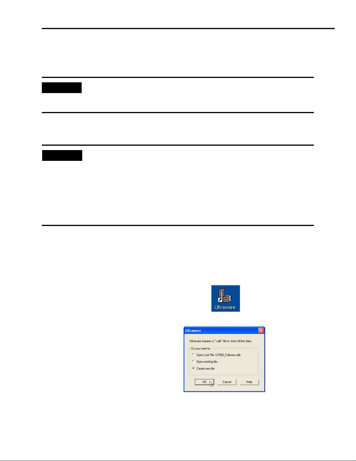
4. Open Ultraware programming software using the
Start menu or the desktop shortcut.
5. Select Create new file.
6. Click OK.
Ultraware will attach to the servo drive.
Publication IASIMP-QS011B-EN-P — January 2009 43
Page 44

Chapter 5 Motion Logix Integration
7. Double-click the drive symbol in the On-Line section to
view its current settings.
You may wish to click Reset EEPROM to Factory Settings if you are not sure what parameters
have been previously changed in the drive.
IMPORTANT
Verify that you removed the ‘Enable’ input in the steps above. The drive may enable and
run if the Enable signal is present.
8. Carefully use the pull-down menu to select the
proper Motor Model from the list.
9. Expand the drive’s Explorer window by clicking the ‘+’ sign
next to the drive symbol.
10.Double-click the DeviceNet folder.
11.Select Assembly Instance 9 for the I/O Receive
Select entry.
12.Set the Poll Transmit Select to Assembly
Instance 12.
13.Verify that the COS/Cyclic Transmit Select
is set to Assembly Instance 10.
These settings allow us to get the most data and diagnostics out of the drive.
44 Publication IASIMP-QS011B-EN-P — January 2009
Page 45

14.For the Logic Command Mask, click the
down arrow to view the pull-down list.
15.Check all the boxes all the way down to
the bottom. Use the scroll bar on the right
to reach them all.
Checking these boxes gives access to all the
commands to the drive over the DeviceNet
network. This eliminates the need for
additional I/O wiring, drive configuration,
and PLC programming.
Motion Logix Integration Chapter 5
16.Change the Enable Behavior selection to
Both.
This requires us to provide a 24V DC ‘drive
enable’ input to the drive (on terminal 31 of the
CN1 connector) but also allows us to command the drive to enable/disable from the
CompactLogix controller over the DeviceNet network.
17.(Optional) You may choose to tune your servo axis at this point.
IMPORTANT
To reduce the possibility of unpredictable motor response, disconnect all loads from
your motors until initial axis tuning is complete. For tuning procedure, refer to the
Ultra3000 Digital Servo Drive Installation Manual, publication 2098-IN003
18.Save your drive setup file.
19.Click ‘Yes’ to the prompt to copy the
on-line values from the drive.
.
Publication IASIMP-QS011B-EN-P — January 2009 45
Page 46

Chapter 5 Motion Logix Integration
20.Exit Ultraware.
IMPORTANT
Repeat all steps in this section for additional Ultra3000 servo drives.
Configure Your Logix DeviceNet Module
Follow these steps to configure your Logix DeviceNet module.
Commission an Out-of-Box DeviceNet Module
IMPORTANT
1. Be sure that all of your CompactLogix controller modules (processor, I/O modules, scanner,
and power supplies) are properly seated on the DIN rail and that the bus interconnect is
properly slid over to the previous module and seated.
2. Apply power to the CompactLogix power supply and wait for the components to power up.
This section is for commissioning an out-of-box DeviceNet scanner module. You do not
need to perform the steps in this section if your scanner is already configured.
3. Connect your workstation to the CompactLogix controller.
• If you are using a serial connection, make sure that you have connected the 1756-CP3 (or
similar) cable between your workstation and one of the 9-pin serial ports on the controller.
• If you are using an Ethernet connection, make sure that you have connected a twisted-pair
cable between your workstation and the controller’s RJ45 connection.
4. Create a communication driver in RSLinx Classic software. If needed, refer to the
CompactLogix System Quick Start Manual, publication IASIMP-QS001
.
5. Open the DeviceNet Node Commissioning Tool by choosing Start>Programs>Rockwell
Software>RSNetWorx>DeviceNet Node Commissioning Tool.
46 Publication IASIMP-QS011B-EN-P — January 2009
Page 47

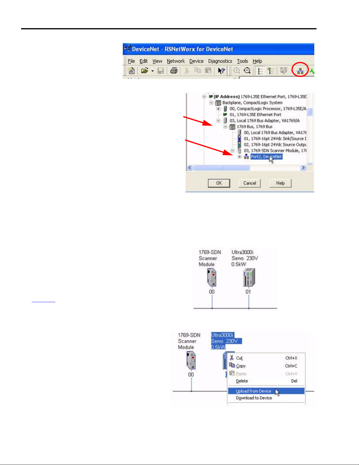
6. Click Browse to begin browsing to your
DeviceNet module.
7. Select the appropriate RSLinx Classic
driver and browse to your controller.
8. Under Backplane, expand the Local
1769 Bus Adapter and the 1769 Bus.
9. Expand the 1769-SDN scanner module.
10.Expand Port2 until you see the
available DeviceNet nodes.
Motion Logix Integration Chapter 5
11.Highlight Node 63, the DeviceNet
module.
12.Click OK (not shown) located at the top right of the window.
13.Click Yes for any additional prompts.
14.After the scanner’s Module Settings appear,
change the Address to ‘00’ and select the
desired network Data rate.
15.Click Apply.
16.After you receive confirmation of the changes, click Close.
Configure the DeviceNet Module
1. Open RSNetWorx for DeviceNet programming
software using the Start menu or the desktop
shortcut.
Publication IASIMP-QS011B-EN-P — January 2009 47
Page 48
Chapter 5 Motion Logix Integration
2. When the software opens,
click the Online button to
go online to your network.
3. Browse to your controller.
4. Under Backplane, expand the Local 1769 Bus
Adapter and the 1769 Bus.
5. Under the 1769-SDN, highlight Port2.
6. Click OK to go online.
7. Click OK again to begin searching for all available network nodes.
8. Click Cancel after all available nodes have been identified. You don’t have to wait for it to
search for nodes you don’t have in your system.
9. Your network should look similar to this.
This reflects a single-axis system. Refer to
the information in Additional Information
for Single and Multi-Axis Systems on
page 50 for using additional axes and for
more detailed information.
10.Right-click Ultra3000 and select Upload
from Device to upload existing parameters
for the Ultra3000 servo drive.
Since there are over 1000 parameters in the
drive, this takes a while.
11.Repeat step 10 to upload parameters for all
additional Ultra3000 drives.
48 Publication IASIMP-QS011B-EN-P — January 2009
Page 49

12.Double-click the 1769-SDN scanner
module to begin configuring the
DeviceNet module.
13.Click the Module tab and select Download if prompted.
This erases any settings in the scanner if it was ever previously used.
14.Set the 1769-SDN scanner module settings
at the bottom of the dialog box as
appropriate for your system.
15.Click Apply.
Motion Logix Integration Chapter 5
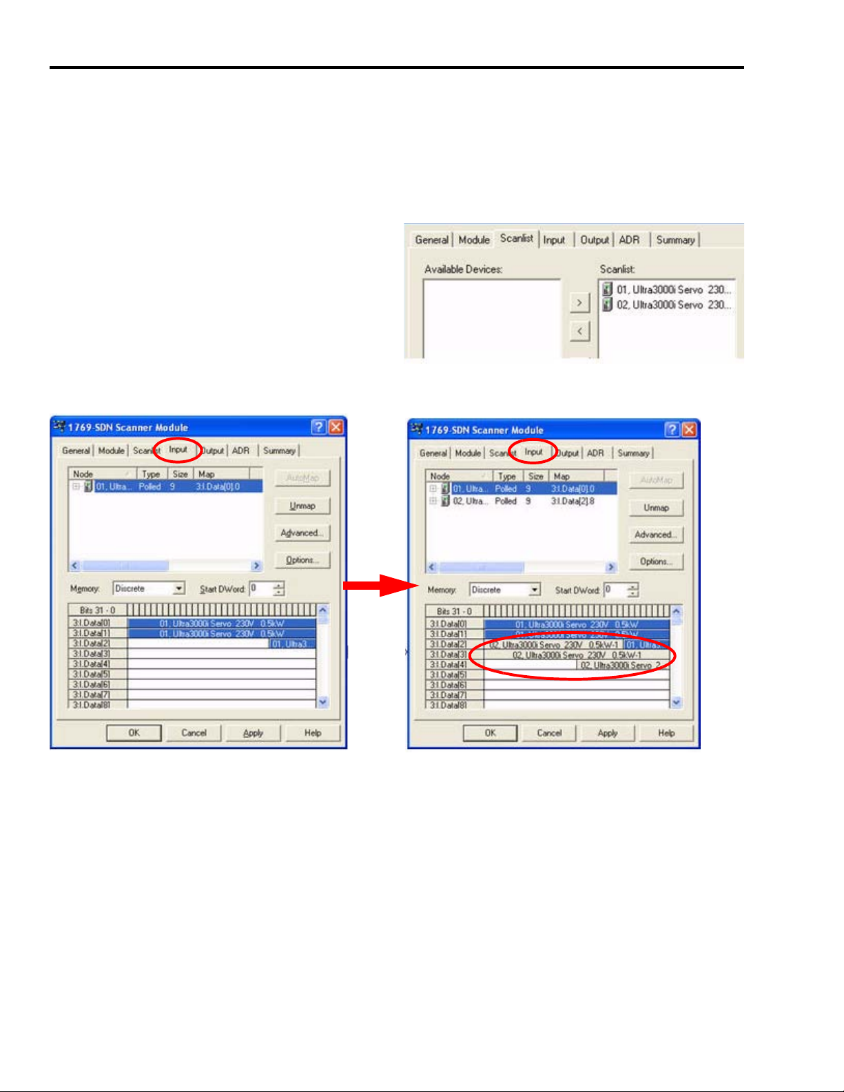
16.Click the Scanlist tab.
17.Automap all available devices into the
scanner by using the >> button.
This allows the controller to connect to the
devices and control the servo drives.
18.Verify that the DeviceNet scanner is in IDLE mode and not in RUN mode.
19.Click OK and click Yes to confirm downloading these changes to the scanner.
20.Save your work.
21.Exit RSNetworx for DeviceNet software.
Publication IASIMP-QS011B-EN-P — January 2009 49
Page 50
Chapter 5 Motion Logix Integration
Additional Information for Single and Multi-Axis Systems
The following information about DeviceNet is for reference only. No action is required. However,
if you do map additional axes, be sure to close RSNetWorx for DeviceNet software before
proceeding.
Additional axes (drives) can be automapped as
shown in step 17 into the DeviceNet module’s
Scanlist.
The Input tabs look similar, but contain more data.
Single-Axis System Double-Axis System
50 Publication IASIMP-QS011B-EN-P — January 2009
Page 51

The Output tabs also look similar, but contain more data.
Motion Logix Integration Chapter 5
Single-Axis System
Double-Axis System
Notice that no custom data mapping is required of the data. Even though the words of data
overlap and multiple drives share the same word boundary, this is handled by the Logix
application code provided on the toolkit with no manual action required.
TIP
The limiting factor for how many drives can be used is based on the module’s available memory
(90 words for the 1769-SDN scanner module) and how much data your devices are configured to
require (2.75 words here). This example would mathematically lead to answer of about 30 drives,
but the network performance would have to be considered before using 30 drives.
Be sure to close RSNetWorx for DeviceNet software before proceeding.
Publication IASIMP-QS011B-EN-P — January 2009 51
Page 52
Chapter 5 Motion Logix Integration
Select Your Logix Application File
Choose the correct file for your system.
Logix Platform Logix File Name Description
CompactLogix L2x CIML2x_1axis_v00x.acd
CIML3x_1axis_v00x.acd
CompactLogix L3x File for Axis
Count
CIML3x_2axis_v00x.acd
CIML3x_3axis_v00x.acd
CompactLogix L2x file pre-configured for single-axis Ultra3000
drive system.
CompactLogix L3x file pre-configured for single-axis Ultra3000
drive system.
CompactLogix L3x file pre-configured for two-axis Ultra3000
drive system.
CompactLogix L3x file pre-configured for three-axis Ultra3000
drive system.
Load and Open Logix Application File
Follow these steps to load and open the Logix application file from the Kinetix Accelerator
Toolkit CD.
1. Open the Kinetix Accelerator Toolkit program. From the Start menu, choose
Programs>Rockwell Automation>Simplification>Kinetix Accelerator Toolkit.
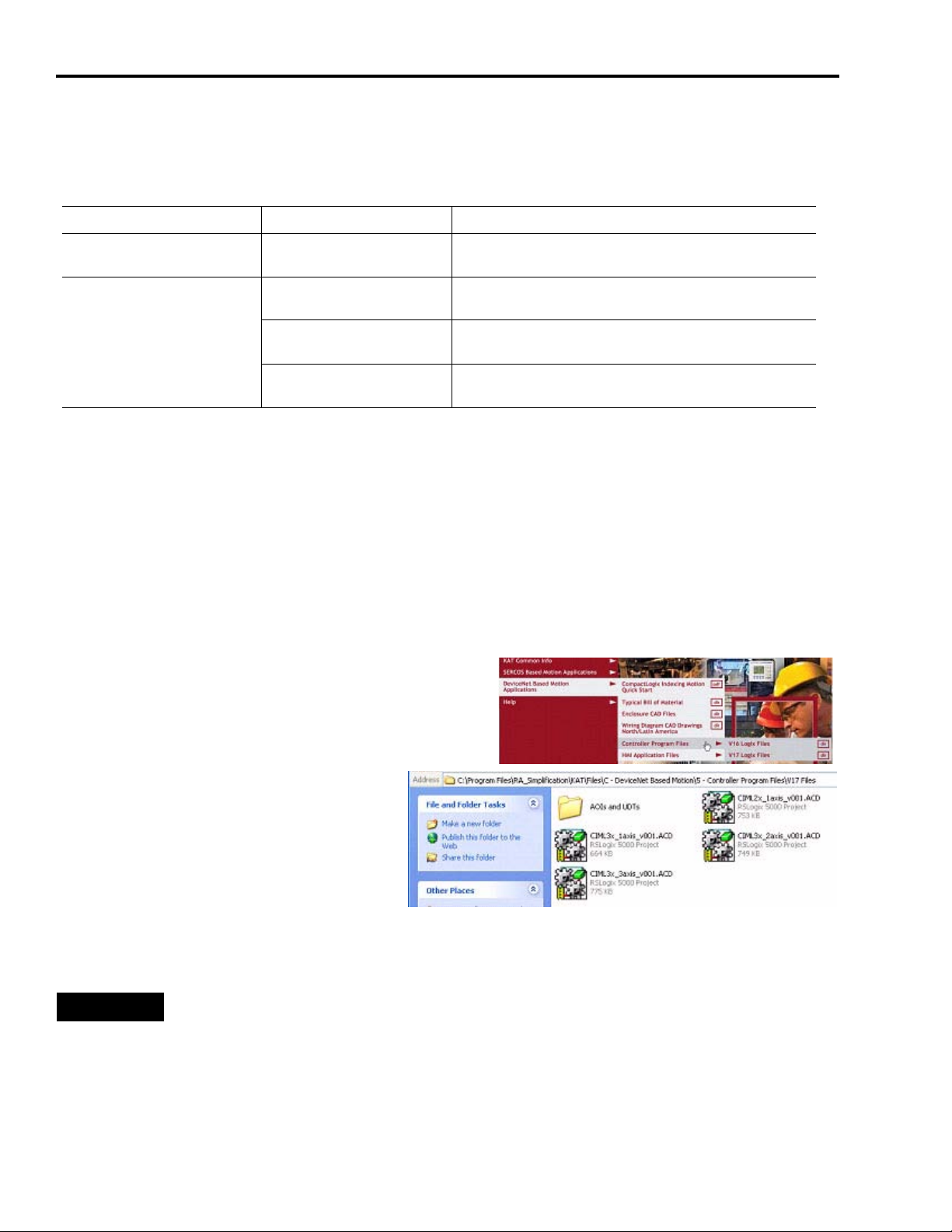
2. From the Toolkit menu, choose DeviceNet Based
Motion Applications>Controller Program Files.
3. Choose between the V16 and V17
CompactLogix Indexing Files folders
based on your current version of
RSLogix 5000 software.
4. Double-click your selected Logix (.acd) application file.
TIP
If your Logix platform is a CompactLogix L2x, select the L2x application file
(CIML2x_1axis_v00x.acd).
If your Logix platform is a CompactLogix L3x, select one of the pre-configured files for
axis count (CIML3x_xaxis_v00x.acd).
52 Publication IASIMP-QS011B-EN-P — January 2009
Page 53

The RSLogix 5000 software launches and
your application file opens.
Configure Your Logix System
Follow these steps to configure your Logix system to your needs.
Motion Logix Integration Chapter 5
Select Your CompactLogix Controller
1. Choose Edit>Controller Properties.
The Controller Properties window opens.
2. Select the General tab.
3. Verify that the controller Type matches your system.
If not, perform the following steps.
a. Click Change Controller to select the controller
type to match your actual hardware.
b. Click OK.
4. Modify the controller Name as appropriate.
5. Click OK.
Publication IASIMP-QS011B-EN-P — January 2009 53
Page 54

Chapter 5 Motion Logix Integration
Changing the Slot Number of the DeviceNet Module
(Optional) If you are using a pre-configured CompactLogix application file
(CIMLxx_xaxis_v00x.acd), your Logix DeviceNet module is configured in slot 5. If this does not
match your actual hardware configuration, follow the steps in this section to change the assigned
slot number.
1. Scroll down to the bottom left of the RSLogix 5000 Explorer window and locate the I/O
Configuration folder.
2. Double-click the 1769-SDN scanner module.
3. Verify the Slot address for this module and change it if
necessary.
4. Click OK to close the properties window.
(Optional) To add additional I/O modules, right-click the
CompactBus Local icon and select New Module.
Changing Controller Tag Names to Match Your Needs
The CompactLogix Indexing Motion application file (CIMLxx_xaxis_v00x.acd) provided in this
toolkit uses generic names for many of the controller tags. Providing useful names for these tags
can aid in troubleshooting your machine. Follow these steps to rename the generic tags in your
RSLogix 5000 program to reflect your needs.
1. In RSLogix 5000 software, expand the
Explorer window to gain access to the
controller tags.
2. Double-click Controller Tags.
3. Make sure the Edit Tags tab is in front.
4. Click the tag GenericMachine_COND and enter a name that better describes the main function
of this machine.
54 Publication IASIMP-QS011B-EN-P — January 2009
Page 55
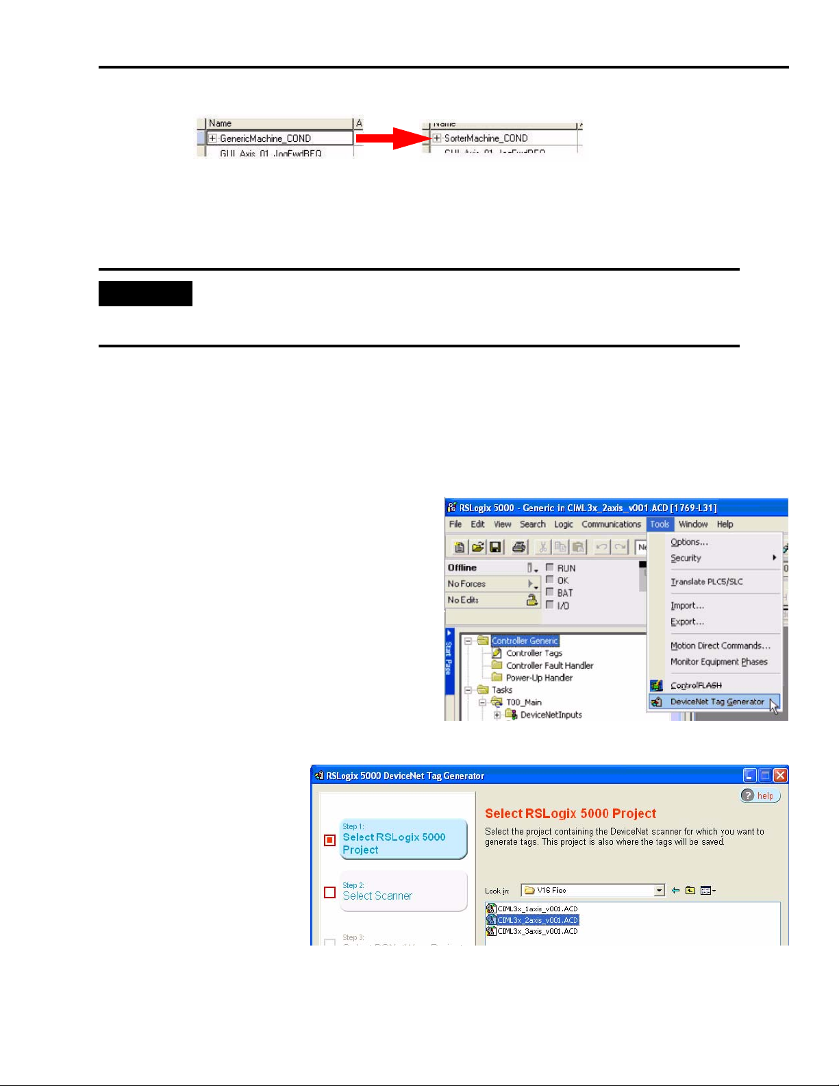
Motion Logix Integration Chapter 5
In this example, GenericMachine_COND is renamed SorterMachine_COND.
Using the DeviceNet Tag Generator
IMPORTANT
You do NOT need to perform the steps in this section if the Ultra3000 drives were
automapped to the DeviceNet scanner module in order, starting at node address 01.
Follow the steps in this section to enable communications to the axes of motion.
Open the DeviceNet Tag Generator
Follow these steps to open the DeviceNet Tag Generator.
1. From the menu in RSLogix 5000, choose
Tools>DeviceNet Tag Generator.
2. Step 1 of the wizard
prompts you to locate
the RSLogix 5000 file
that you are presently
using. Browse to the
location of your Logix
application file and
double-click it. This
selects the file and
moves to the next step
of the wizard.
Publication IASIMP-QS011B-EN-P — January 2009 55
Page 56

Chapter 5 Motion Logix Integration
3. For wizard Step 2, locate
and double-click the
DeviceNet scanner
configured earlier in this
chapter.
4. For wizard Step 3, locate
and double-click the
DeviceNet configuration
file saved earlier in this
chapter.
5. For wizard Step 4, locate
and double-click the
DeviceNet scanner
node.
6. For wizard Step 5, click
Generate Tags to finalize
the process.
56 Publication IASIMP-QS011B-EN-P — January 2009
Page 57

Motion Logix Integration Chapter 5
7. Click Yes to the prompt
about inserting tags and
logic.
8. There may be a warning that tags were created, but close the DeviceNet Tag Generator tool
and return to your RSLogix 5000 project.
9. The program logic that was created can be found in the
Tasks folder of the project.
Do not make any changes to these programs or logic,
as your DeviceNet nodes may quit responding.
Link the New Tags to the DeviceNet Drives
These steps link the tags created by the tool to the axes programmed in the logic.
1. Double-click Controller Tags in the controller
Explorer window to open the tag editor.
2. At the bottom of the editor window that
opens, click the Edit Tags tab to enable
editing.
Publication IASIMP-QS011B-EN-P — January 2009 57
Page 58
Chapter 5 Motion Logix Integration
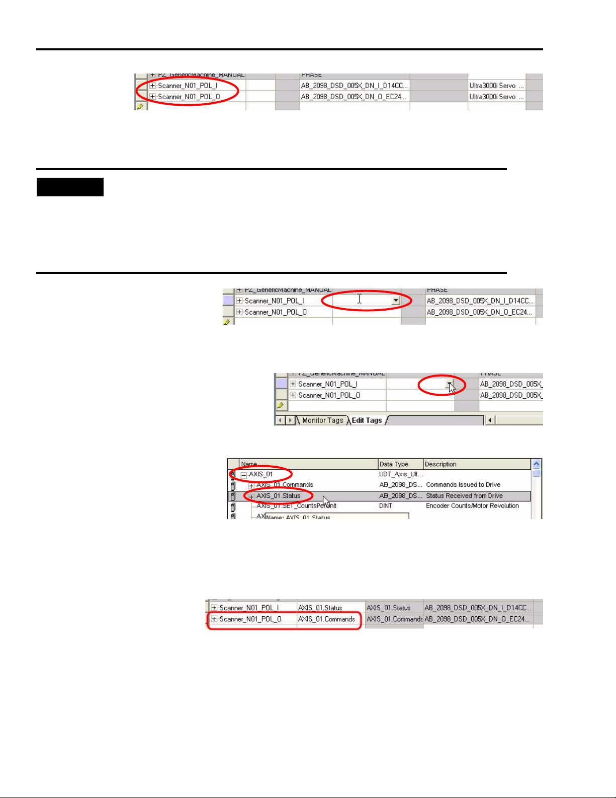
3. Scroll to the
bottom of the
tag editor
and locate
the tags created by the Tag Generator tool. The name of the tags will start with the name you
gave the DeviceNet scanner, ‘Scanner’ in our case.
TIP
• The ‘Nxx’ indicates the DeviceNet node address assigned to each component.
• The ‘I’ or ‘O’ indicates whether the data is an Input or an Output in reference to
the DeviceNet scanner module.
• Scanner Inputs are the status coming back from the DeviceNet components.
• Scanner Outputs are the commands being issued to the DeviceNet components.
4. You will need to associate
these tags to the existing axis
logic provided in the Logix
application file. In the ‘Alias For’ column next to the Scanner_N01_POL_I tag, click inside the
box to enable the tag browser.
5. Open the tag browser by clicking the
arrow.
6. The axes of motion provided
in the RSLogix 5000 sample file
are named ‘AXIS_01’
(’AXIS_02’ for the 2-axis
version and so on). Expand the
AXIS_01 entry and locate the Status tag. Double-click it to select it and close the tag browser.
This links the Status of the Ultra3000 drive at DeviceNet node 01 to the AXIS_01 programming
logic and controller tag in the RSLogix 5000 sample file.
7. Similarly, alias the
Scanner_N01_POL_O tag
to the ‘Commands’ tag of
AXIS_01.
8. If you have more than one servo drive, repeat this process to alias the remaining nodes to the
axis programming. Be sure to alias the ‘I’ input data to the Status tag and the ‘O’ output data
to the Commands tag for each device.
58 Publication IASIMP-QS011B-EN-P — January 2009
Page 59
Motion Logix Integration Chapter 5
Configure Axis Properties
Follow these steps to configure the axes of motion.
Modify Axis Names
The CompactLogix Indexing Motion application file (CIMLxx_xaxis_v00x.acd) contains program
code for up to three axes, however, you may want to rename the axes from AXIS_0x to
something more meaningful for your application. Providing useful names for these axes can aid
in troubleshooting your machine. Follow these steps to rename the generic axes in your RSLogix
5000 program to reflect your needs.
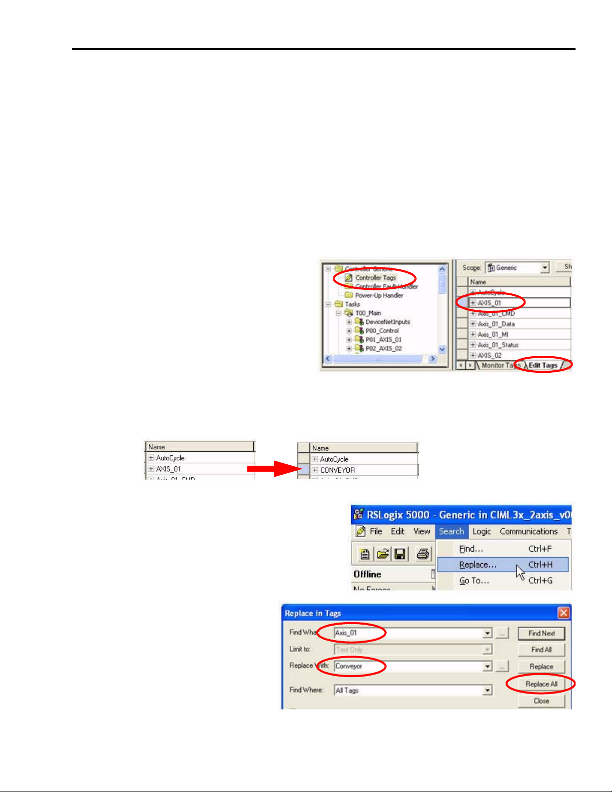
1. In RSLogix 5000 software, expand the
Explorer window to gain access to the
controller tags.
2. Double-click Controller Tags.
3. Make sure the Edit Tags tab is in front.
4. Click AXIS_01 and enter a name that
better describes the main function of this
axis.
In this example, AXIS_01 is renamed CONVEYOR.
5. There are additional tags associated with each
axis. With the Controller Tag dialog box still
open, choose Search>Replace.
6. Rename all tags with Axis_01 with
your new axis name.
7. Click Replace All.
8. When the process has completed,
click Close.
Publication IASIMP-QS011B-EN-P — January 2009 59
Page 60

Chapter 5 Motion Logix Integration
9. Repeat step 4…step 8 for each additional axis.
The result might look like this.
Set the Axis k Constant
The CompactLogix Indexing Motion application file (CIMLxx_xaxis_v00x.acd) allows you to
program all motion instructions in user units (inches or degrees, for example) instead of encoder
counts. You will need to set the conversion factor (or k constant) from user units to encoder
counts to allow the drive to be commanded properly. Follow these steps to set the k constant for
each axis in your RSLogix 5000 program.
1. In RSLogix 5000 software, expand the
Explorer window to gain access to the
controller tags.
Double-click Controller Tags.
2. Make sure the Monitor Tags tab is in
front.
3. Locate and expand the tag for each axis in your system. You may have renamed them from
their original AXIS_0x name.
The third tag element in the list for each axis is the name.SET_CountsPerUnit tag. This is
where the k constant is entered.
4. If needed, consult the documentation for your
mechanical system components and your servo
motor to calculate your k constant. Enter the
number of encoder counts per desired user unit
in the space provided.
All values entered in your Logix motion
instructions will now be scaled by this value.
IMPORTANT
Please note this scaling effect when entering your desired speeds, positions, and acceleration
rates in your motion instructions.
60 Publication IASIMP-QS011B-EN-P — January 2009
Page 61

5. Repeat step 3 and step 4 for each additional axis.
Motion Logix Integration Chapter 5
TIP
For a better understanding of the code provided in the sample file, as well as the benefits of
PhaseManager, refer to Appendix A, CompactLogix Base Program Overview on page 95.
Configure Logix Communications
This procedure assumes that your communication method to the Logix controller is using the
Ethernet protocol. It is also assumed that your Logix Ethernet module has already been
configured. For additional information, refer to the CompactLogix Controllers User Manual,
publication 1769-UM011.
Follow these steps to configure Logix Communications.
1. Apply power to your Logix chassis/personal computer containing the DeviceNet interface
module.
2. Open the RSLinx Classic software and choose Communications>Configure Drivers.
The Configure Drivers window
opens.
3. Choose the Ethernet Devices
driver from the pull-down list.
4. Click Add New.
The Add New RSLinx Classic
Driver window opens.
5. Name the new driver.
6. Click OK.
The Configure driver window opens.
7. Enter the IP address of your Logix Ethernet
Module.
Publication IASIMP-QS011B-EN-P — January 2009 61
Page 62
Chapter 5 Motion Logix Integration
The IP address shown is an example. Yours will be different.
TIP
If your Logix Ethernet module is already configured, the IP address is displayed on the module.
8. Click OK.
9. Click Close in the Configure Drivers window.
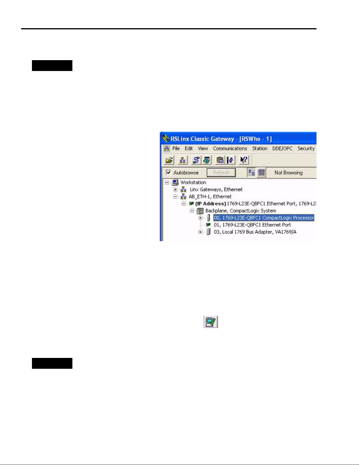
10.Choose Communication>RSWho.
The RSWho window opens.
11.Expand the 1769 Ethernet Port and then
expand the Backplane.
12.Verify that you can browse to your Logix
controller. If not, repeat step 1…step 11,
checking for any errors.
13.Minimize the RSLinx Classic application
window and return to the RSLogix 5000
project window.
Save and Download Your Program
After completing the Logix configuration, you must download your program to the Logix
controller.
Follow these steps to save and download your program.
1. On the RSLogix 5000 toolbar, click Verify Controller.
The system verifies your Logix controller program and
displays errors/warnings, if any.
TIP
2. Choose File>Save As to save the file.
If you receive warnings related to AXIS_Servo_Generic, they are due to the Fault Event Log
configuration and can be ignored.
62 Publication IASIMP-QS011B-EN-P — January 2009
Page 63
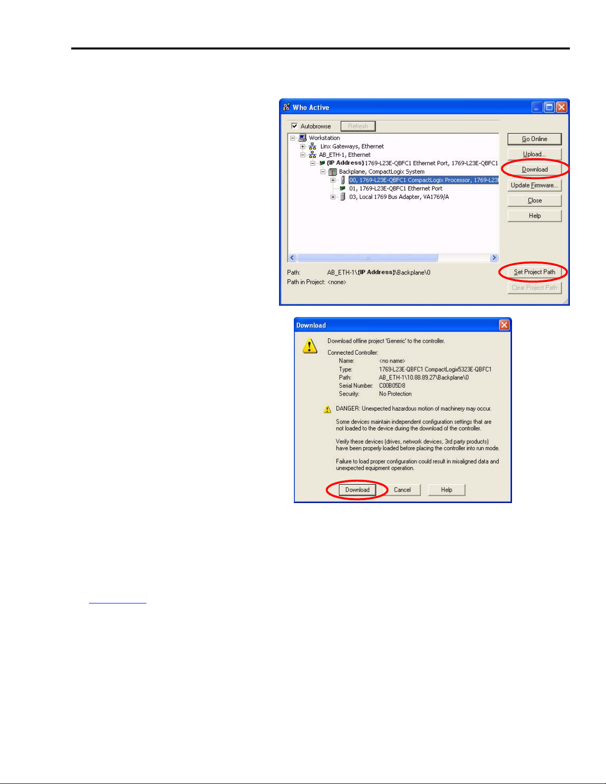
3. Choose Communications>Who Active.
The Who Active window opens.
4. Browse to your Logix controller
and click Set Project Path.
5. Verify that the key switch on your
controller module is in the REM
(remote) position.
6. Click Download.
The Download window opens.
Motion Logix Integration Chapter 5
7. To send the program to the Logix
controller, click Download.
8. Verify that the three Logix DeviceNet module indicators are green. (Some may be flashing.)
9. Verify that the Ultra3000 servo drive LED indicators are both green. (Some may be flashing.)
If steps 8 or 9 fail, refer to the Ultra3000 Digital Servo Drive Installation Manual, publication
2098-IN003
, for troubleshooting tables.
10.Choose Communications>Run Mode.
Publication IASIMP-QS011B-EN-P — January 2009 63
Page 64

Chapter 5 Motion Logix Integration
Notes:
64 Publication IASIMP-QS011B-EN-P — January 2009
Page 65

Chapter
6
Motion FactoryTalk View Integration
In this chapter, you configure your FactoryTalk View ME application file. FactoryTalk View ME
application files (.apa) are included in the Kinetix Accelerator Toolkit.
You can choose:
• 1-, 2-, or 3-axis pre-configured FactoryTalk View ME application file for PanelView Plus 600
terminals.
• 2-axis generic base application file for a variety of PanelView Plus terminals.
After file selection, you configure the communications, add axes if needed, test the project,
download the program, and run the application.
Before You Begin
• Complete the Kinetix Accelerator Toolkit CD installation. (Refer to Chapter 1.)
• Complete your system hardware selection. (Refer to Chapter 2.)
• Complete your system layout. (Refer to Chapter 3.)
• Complete your system wiring. (Refer to Chapter 4.)
• Complete your Logix Integration procedures. (Refer to Chapter 5.)
What You Need
• Kinetix Accelerator Toolkit CD, publication IASIMP-SP004
• FactoryTalk View Studio software, version 5.00 or later
• RSLinx Enterprise software, version 2.54 or later
• FactoryTalk View ME application files (CIMME_xaxis_U3k_PVP600_v00x.apa)
FactoryTalk View ME files are available on the Kinetix Accelerator Toolkit CD. For a copy of
the CD, contact your local Rockwell Automation distributor or sales representative.
Publication IASIMP-QS011B-EN-P — January 2009 65
Page 66

Chapter 6 Motion FactoryTalk View Integration
Follow These Steps
Complete the following steps to configure your FactoryTalk View ME Indexing Motion
application.
Start
Select Your FactoryTalk
View ME Application File
page 67
Load and Restore the
FactoryTalk View ME
Application
page 67
Configure Local
Communications
page 69
Configure Target
Communications
page 71
Adding Axes to
the Project
page 72
Test the Project
page 79
Download Fonts to
the Terminal
page 80
Download the Project
to a Terminal
page 81
Run the Project on
a Terminal
page 83
66 Publication IASIMP-QS011B-EN-P — January 2009
Page 67
Motion FactoryTalk View Integration Chapter 6
Select Your FactoryTalk View ME Application File
PanelView Terminal FactoryTalk View ME File Name Description
CIMME_1axis_U3k_PVP600_v00x.apa
PanelView Plus 600
PanelView Plus 700/1000 CIMME_ U3k_PVP700_1000_v00x.apa
PanelView Plus 1250 CIMME_ U3k_PVP1250_v00x.apa
PanelView Plus 1500 CIMME_ U3k_PVP1500_v00x.apa
CIMME_2axis_U3k_PVP600_v00x.apa
CIMME_3axis_U3k_PVP600_v00x.apa
PanelView Plus 600 terminal pre-configured for single-axis
Ultra3000 drive system.
PanelView Plus 600 terminal pre-configured for two-axis
Ultra3000 drive system.
PanelView Plus 600 terminal pre-configured for three-axis
Ultra3000 drive system.
FactoryTalk View ME file for generic base application. Can be
configured for any Ultra3000 drive configuration and PanelView
Plus terminal.
Load and Restore the FactoryTalk View ME Application
Follow these steps to load and restore the FactoryTalk View ME application file from the Kinetix
Accelerator Toolkit CD.
1. Open the Kinetix Accelerator Toolkit program. From the Start menu, choose
Programs>Rockwell Automation>Simplification>Kinetix Accelerator Toolkit.
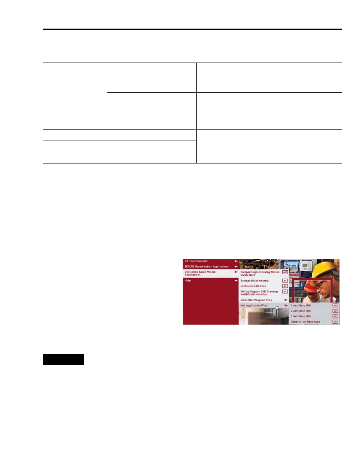
2. From the Toolkit menu, choose
DeviceNet Based Motion Applications
>HMI Application Files.
3. Select the appropriate HMI directory
based on the table above.
4. Double-click your selected FactoryTalk View ME (.apa) application file.
TIP
If you are using any PanelView Plus terminal with any axis count, select the generic
base application file (CIMME_PVPxxxx_v00x.apa).
If you are using the PanelView Plus 600 terminal for a specific axis count (up to three
axes), select one of the pre-configured files for axis count (CIMME_xaxis_PVP600_
v00x.apa).
Publication IASIMP-QS011B-EN-P — January 2009 67
Page 68

Chapter 6 Motion FactoryTalk View Integration
The Application Manager window opens.
5. Select Restore the FactoryTalk View Machine
Edition application.
6. Click Next.
Another Application Manager window
opens.
IMPORTANT
Selecting Restore the FactoryTalk View Machine Edition application and FactoryTalk Local
Directory will cause the local security settings on your personal computer to substitute for the
security setting from the pre-configured application.
In this example the
CIMME_1axis_U3k_PVP600_v001.apa file
is selected. Yours could be different.
7. Click Finish.
After file restoration is complete, the
application closes.
68 Publication IASIMP-QS011B-EN-P — January 2009
Page 69

Motion FactoryTalk View Integration Chapter 6
Configure Local Communications
The Local tab in Communications Setup reflects the view of the topology from the RSLinx
Enterprise server on the development computer. In this example application, the development
computer is communicating to the CompactLogix L32E controller via Ethernet network. Other
CompactLogix controllers and communication networks can also be selected.
Follow these steps to configure local communications.
1. Apply power to your CompactLogix controller.
2. Connect your motion system communication network cable to your CompactLogix controller
and personal computer.
3. Open the FactoryTalk View Studio software.
The New/Open Machine Edition
Application window opens.
4. Click the Existing tab.
5. Select your FactoryTalk View ME
application file.
CIMME_1axis_U3k_PVP600_v001 is used
in this example.
6. Click Open.
The FactoryTalk View Studio - Machine Edition window opens.
7. Expand RSLinx Enterprise in the Explorer
window.
8. Double-click Communications Setup.
Publication IASIMP-QS011B-EN-P — January 2009 69
Page 70
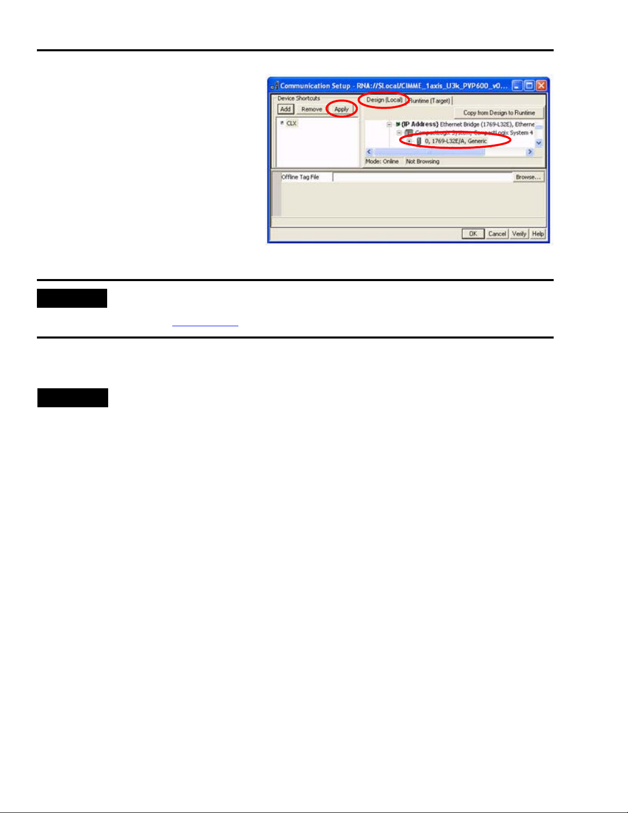
Chapter 6 Motion FactoryTalk View Integration
The Communications Setup window
opens.
9. Click the Design (Local) tab.
10.Select the CLX device shortcut.
11.Expand the RSLinx Enterprise tree to
gain access to your CompactLogix
controller.
12.Select your CompactLogix controller.
0, 1769-L32E is used in this example. The slot number is 0. Yours could be different.
IMPORTANT
RSLinx Enterprise will autobrowse to the controller if the controller is available on the network. If
RSLinx Enterprise fails to find your controller, refer to CompactLogix System Quick Start manual,
publication IASIMP-QS001.
13.In the Device Shortcuts section, click Apply.
TIP
If you select the device shortcut (CLX), the 1769-L32E CompactLogix controller is highlighted. This
indicates that the shortcut is correctly mapped to the controller, and communication exists
between the controller and your application on the development computer.
70 Publication IASIMP-QS011B-EN-P — January 2009
Page 71

Motion FactoryTalk View Integration Chapter 6
Configure Target Communications
The Target tab displays the offline configuration from the perspective of the device that is
running the application and comprises the topology that is loaded into the PanelView Plus
terminal. In this example application, the PanelView Plus terminal communicates to the same
CompactLogix L32E controller via Ethernet.
Follow these steps to configure target communications.
1. Click the Design (Local) tab in the
Communication Setup window.
2. Click Copy from Design to Runtime.
This RSLinx Enterprise message
window opens.
3. Click Yes.
4. Click the Runtime (Target) tab and
expand the RSLinx Enterprise tree.
5. Verify that your controller and
shortcut name are both highlighted.
This indicates that communication is
established.
In this example, 1769-L32E is the
controller and CLX is the shortcut.
6. Click OK.
Publication IASIMP-QS011B-EN-P — January 2009 71
Page 72

Chapter 6 Motion FactoryTalk View Integration
Adding Axes to the Project
IMPORTANT
If you have selected a pre-configured application with a specific axis count and it fits your
application needs, skip this section and go to Modifying Axis Names beginning on page 77.
The CIMME_U3k_PVPxxxx_v00x.apa file has two pre-configured axes for use. In this section you
will add additional axes to your Ultra3000 drive system and the project file.
All the displays in the project file are parameterized to facilitate quick editing and reuse
throughout the application. The following Axis Status display contains faults and status
information that is common to all configured axes (Axis1…Axisx).
Axis Status Display
Add the Parameter File
Follow these steps to add a parameter file to your FactoryTalk View ME application.
1. Expand the FactoryTalk View ME Explorer window to gain access to
Parameters.
The parameters list contains the pre-configured axes within the
application. Each parameter file is associated with a specific axis. When
opening the Axis Status display, the tag information loads from the axis
currently selected.
72 Publication IASIMP-QS011B-EN-P — January 2009
Page 73

Motion FactoryTalk View Integration Chapter 6
2. Right-click Axis x Status and select Duplicate.
The Save component name window opens.
3. Name the new parameter file.
In this example, there are two existing
pre-configured axes. We are duplicating and
renaming the Axis 1 Status parameter file. The
new name is Axis 3 Status. Yours could be
different.
4. Click OK.
5. Double-click the Axis 3 Status parameter file created in step 3.
The Axis x Status - CIMME_U3k_PVPxxxx_v00x/Parameters window
opens.
In each parameter file, there are three references to specific tags or
partial strings. The # before a number indicates a parameterized tag. (The ! before any text
indicates that line is a comment.)
Parameter #1 contains the shortcut name (CLX in this example). This should match the
shortcut name used in step 10 on page 70.
Parameter #2 represents the specific axis from which you will be requesting data.
Parameter #3 is a string memory tag that exists in the tag database editor. A new tag must be
created each time a new axis is created so that the displays are updated correctly.
IMPORTANT
All pre-configured application files have four SelectedAxisx memory tags created for them.
New tags must be created for axis counts of five or more.
Publication IASIMP-QS011B-EN-P — January 2009 73
Page 74
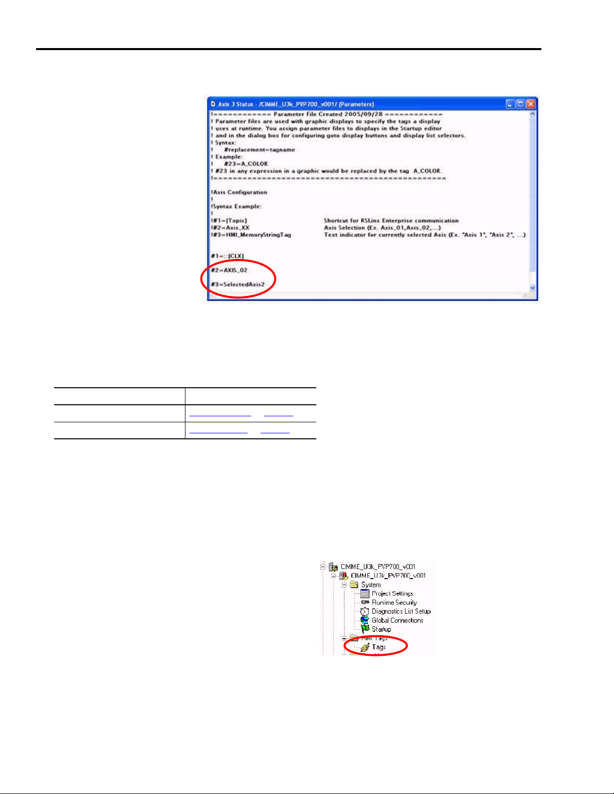
Chapter 6 Motion FactoryTalk View Integration
6. Edit parameters 2 and 3.
In this example:
#2 = AXIS_02
becomes
#2 = AXIS_03
#3 = SelectedAxis2
becomes
#3 = SelectedAxis3
7. Choose File>Save.
8. Repeat step 2…step 7 as necessary for your axis count.
9. The pre-configured application files include HMI tags for up to four axes.
If your axis count is Then go to
Four or less Edit Display Files
Five or more Add an HMI Tag on page 74
on page 75
Add an HMI Tag
In this section, you create an HMI string tag for each parameter file (for Axis 5 or greater) created
Add the Parameter File.
in
Follow these steps to add an HMI tag to your FactoryTalk View ME application.
1. Expand your application file in the Explorer
window.
2. Double-click Tags.
The Tags editor window opens.
74 Publication IASIMP-QS011B-EN-P — January 2009
Page 75
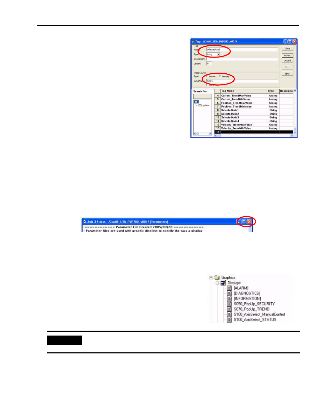
Motion FactoryTalk View Integration Chapter 6
3. Click the first empty row in the Tags editor
window.
Row 14 is used in this example. Yours could be
different.
4. Enter ‘SelectedAxisx’ in the Name field.
SelectedAxis5 is used in this example. Yours could
be different.
5. Select String from the pull-down menu in the Tag
Type field.
6. Select Memory in the Data Source Type field.
7. Enter ‘Axis x’ in the Initial Value field.
Axis 5 is used in this example. Yours could be different. This is the text that is displayed on
the graphic display.
8. Click Accept. (Leave default values for Description and Length as is.)
9. Repeat step 3…step 8 for each newly created parameter file (for Axis 5 or greater).
10.Click the Close button <X> in the Axis x Status parameter file window to close the window.
Edit Display Files
Follow these steps to edit the display files.
1. Return to the Explorer window and expand the Displays
editor.
In this example, these are the displays that are visible.
Yours could be different.
IMPORTANT
All displays containing the text ‘AxisSelect’ require updating for each new parameter file
created in Add the Parameter File on page 72.
2. Double-click the S100_AxisSelect_ManualControl display, or the first AxisSelect display in the
list of displays.
Publication IASIMP-QS011B-EN-P — January 2009 75
Page 76

Chapter 6 Motion FactoryTalk View Integration
The Axis Selection display dialog box opens.
3. Right-click the last axis shown (Axis 2
for this example.)
4. Select Copy.
5. Right-click under Axis 2 (or the last
axis shown) and select Paste.
6. Click the pasted axis (new Axis 2 in this example), drag and drop the axis in line beneath the
others.
7. Right-click the new axis
and select Properties.
New Axis
The Goto Display Button Properties window opens.
8. Click … to browse for the parameter file.
The Component Browser window opens.
9. Select the new axis (in this example, Axis 3
Status).
10.Click OK.
76 Publication IASIMP-QS011B-EN-P — January 2009
Page 77
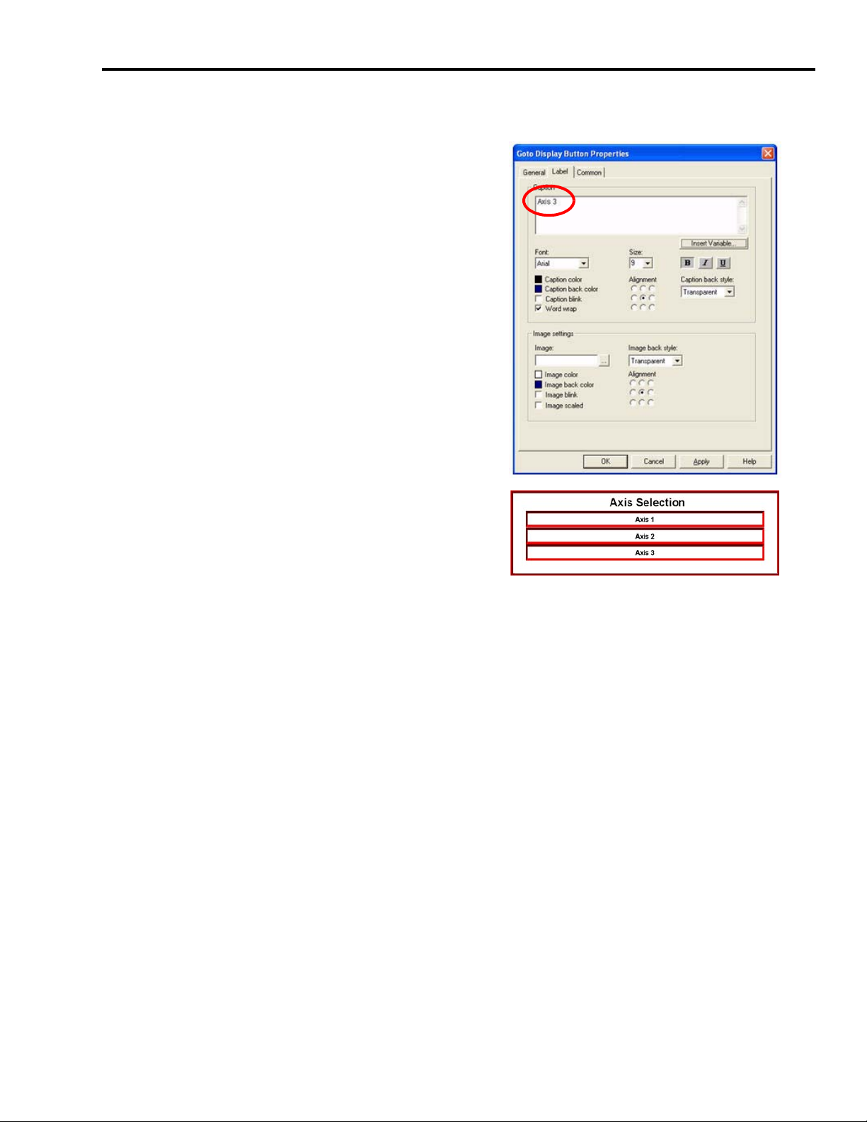
Motion FactoryTalk View Integration Chapter 6
11.Return to the Goto Display Button Properties window and select the Label tab.
12.Edit the text in the Caption field.
In this example Axis 2 becomes Axis 3.
13.Click OK to close the Goto Display Button
Properties window.
14.Verify that Axis Selection now includes your new
axis (Axis 3 in this example.)
15.Repeat step 1…step 14 for each new axis and each of the AxisSelect displays identified in step
1.
Modifying Axis Names
Your FactoryTalk View ME application file (CIMME_U3k_PVPxxxx_v00x) now contains program
code for three axes. However, you may want to rename the axes from AXIS_01, AXIS_02, and
AXIS_03 to something more meaningful for your application, like Conveyor, for example.
Publication IASIMP-QS011B-EN-P — January 2009 77
Page 78
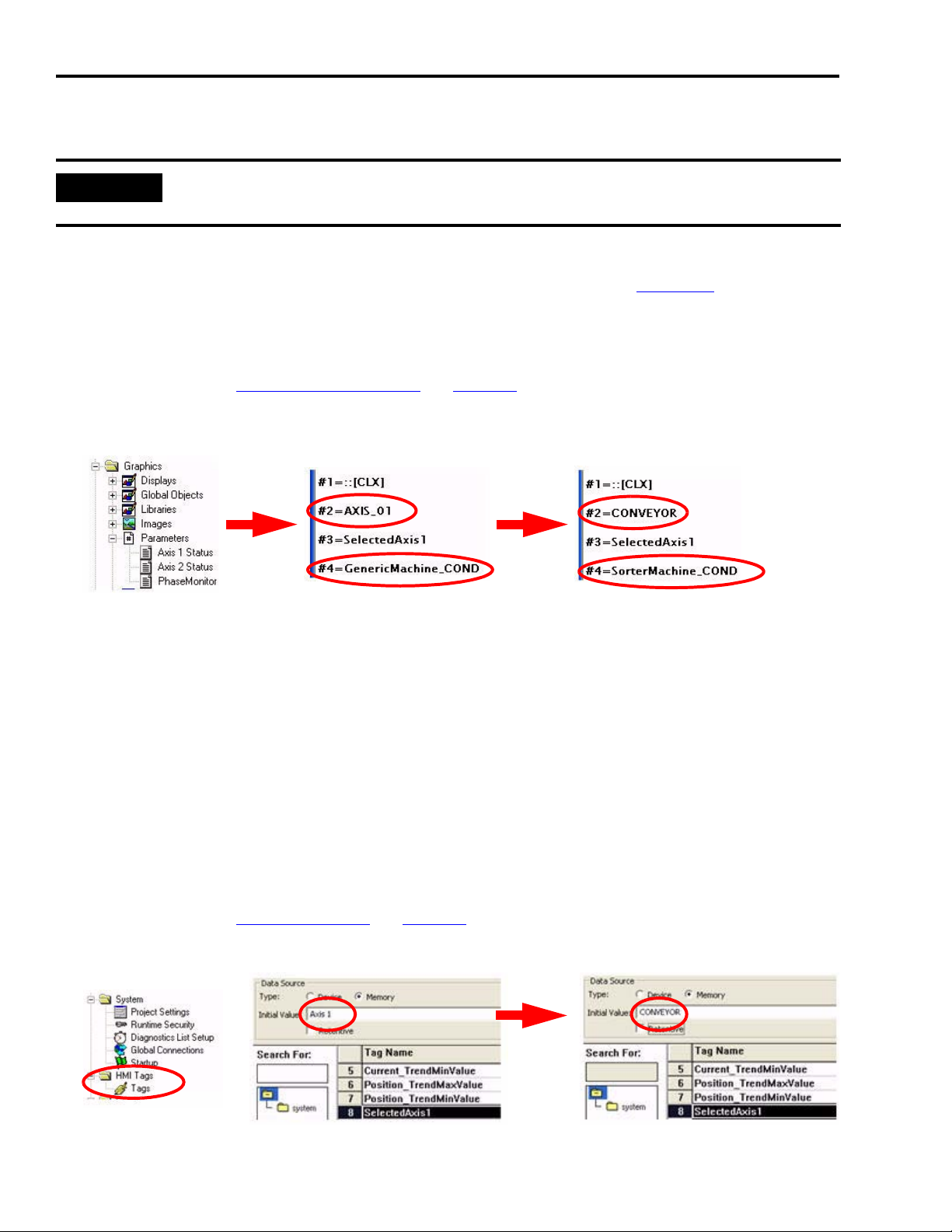
Chapter 6 Motion FactoryTalk View Integration
Edit Axis Shortcuts
IMPORTANT
Follow these steps to rename the axes in your FactoryTalk View ME program if you changed the
names of the axes in your CompactLogix application file.
In this example, AXIS_01 is renamed CONVEYOR and GenericMachine_COND is renamed
SorterMachine_COND to match the changes in our Logix application in Chapter 5 Motion Logix
Integration.
1. In FactoryTalk View ME software, expand the Explorer window to gain access to Parameters.
If needed, refer to Add the Parameter File on page 72 to see how that was done.
2. Double-click the Axis 1 Status file.
3. Rename the #2 and the #4 shortcut to match the axis and machine names used in your
RSLogix 5000 program file.
4. Repeat step 2…step 3 for each axis to rename the shortcuts.
Edit Axis Display Names
Follow these steps to provide meaningful names to the axes as they are displayed on the operator
interface. You will change the Initial Value field for the HMI tags. In this example, Axis 1 is
renamed Conveyor.
1. In FactoryTalk View ME software, expand the Explorer window to gain access to HMI tags.
If needed, refer to Add an HMI Tag
2. Rename the Initial Value field to match the axis name used in your RSLogix 5000 program file.
on page 74 to see how that was done.
78 Publication IASIMP-QS011B-EN-P — January 2009
Page 79
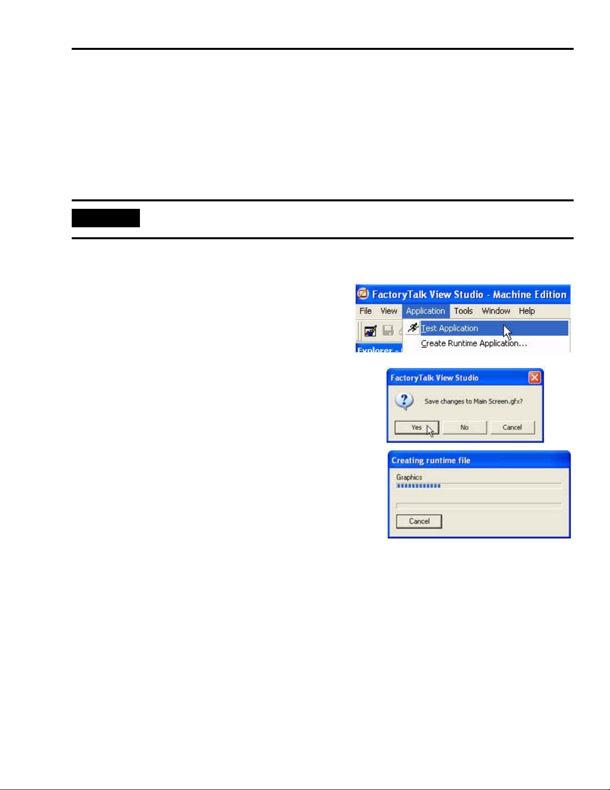
Motion FactoryTalk View Integration Chapter 6
3. Repeat step 2 for each SelectedAxisx HMI tag.
Test the Project
FactoryTalk View Studio lets you create and test individual displays or the entire project, so that
you can navigate and test all the functionality before downloading your project to a terminal.
IMPORTANT
To test run the project, all communications must be configured first.
Follow these steps to test your FactoryTalk View Studio project.
1. Choose Application>Test Application.
2. If prompted to save changes, click Yes.
3. The FactoryTalk View Studio software compiles the
project and runs it as if it were executing on the desired
terminal.
4. Press ‘x’ to end testing and shut down the application.
Publication IASIMP-QS011B-EN-P — January 2009 79
Page 80

Chapter 6 Motion FactoryTalk View Integration
Download Fonts to the Terminal
Because PanelView Plus terminals do not include the Arial Bold font when shipped but the
FactoryTalk View ME applications require this font, it is necessary to download Arial Bold from
your personal computer to the PanelView Plus terminal.
Follow these steps to download fonts to the PanelView Plus terminal.
1. Apply power to the PanelView Plus terminal.
2. Connect your Ethernet cable between your PanelView Plus terminal and personal computer.
3. Choose Tools>Transfer Utility.
The Transfer Utility window
opens.
4. Click … to browse for the source
font file.
The Select File to Download
window opens.
5. Navigate to C:\WINDOWS\Fonts.
6. Select True Type Font Files in the
Files of type field.
7. Enter ‘Arialbd.ttf’ in the File name
field.
8. Click Open.
80 Publication IASIMP-QS011B-EN-P — January 2009
Page 81
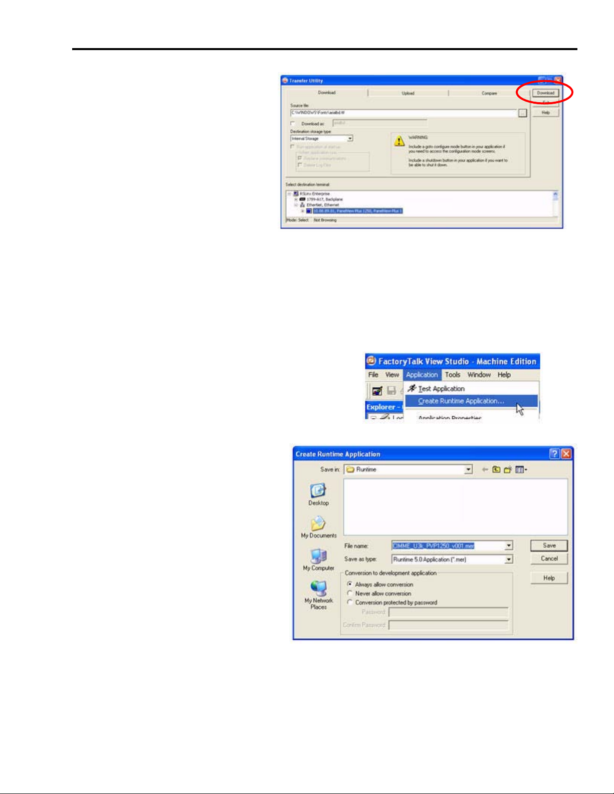
Motion FactoryTalk View Integration Chapter 6
The Transfer Utility window
returns.
9. Expand the Ethernet, Ethernet
driver.
10.Select your PanelView Plus
terminal.
11.Click Download.
The font transfers to the terminal.
Download the Project to a Terminal
Follow these steps to download your FactoryTalk View Studio project.
1. Choose Application>Create Runtime Application.
The Create Runtime Application
window opens.
2. For Save as type:, select Runtime 5.0
Application (*.mer).
3. For Filename, enter a file name for
the application.
CIMME_U3k_PVP1250_v001.mer is
used in this example.
4. Click Save.
Publication IASIMP-QS011B-EN-P — January 2009 81
Page 82

Chapter 6 Motion FactoryTalk View Integration
5. Click the File Transfer Utility button on the tool
bar.
The Transfer Utility window opens.
6. Click … to browse for the
runtime file.
7. Select
CIMME_U3k_PVP1250_v001.mer.
8. Click Open.
82 Publication IASIMP-QS011B-EN-P — January 2009
Page 83

9. Browse for your PanelView
Plus terminal.
10.Select Download.
The file transfers to the
PanelView Plus terminal.
11.Click OK.
12.Click Exit to close the Transfer Utility window.
13.Choose File>Close to close the application.
Motion FactoryTalk View Integration Chapter 6
Run the Project on a Terminal
Follow these steps to run your project on the PanelView Plus terminal.
1. Apply power to the PanelView Plus terminal.
2. Connect your motion system communication network cable to your PanelView Plus terminal
and personal computer.
The FactoryTalk View ME Station window
opens.
3. Click Load Application.
Publication IASIMP-QS011B-EN-P — January 2009 83
Page 84

Chapter 6 Motion FactoryTalk View Integration
The Load Application window opens.
4. Scroll through the list of application files by
using the up/down arrows and select the .mer
file you intend to run.
CIMME_U3k_PVP1257000_v001.mer is used in
this example.
5. Click Load.
The Replace Communications window opens.
6. Click Yes.
If you click No, the communications settings
from the project run previously will be used
instead.
The FactoryTalk View ME Station window
returns.
7. Verify that the
CIMME_U3k_PVP1257000_v001.mer file
appears in the current application field.
8. Click Run Application.
9. Verify the functionality of the application.
Refer to Chapter
7 for a basic understanding of how to run a general motion system
application.
84 Publication IASIMP-QS011B-EN-P — January 2009
Page 85

Chapter
7
Motion System Application Guide
In this chapter, you are guided through the pre-configured FactoryTalk View ME application that
interfaces with the pre-configured Logix program that controls your base motion system. You will
run your motion system in Manual mode and Auto mode, and use the built-in axis status and
diagnostics.
Before You Begin
• Complete your system hardware selection. (Refer to Chapter 2.)
• Complete your system layout. (Refer to Chapter 3.)
• Complete your system wiring. (Refer to Chapter 4.)
• Complete your Logix Integration procedures (refer to Chapter 5) and download the Logix
program to your controller.
• Complete your FactoryTalk View ME Integration procedures (refer to Chapter 6) and
download the FactoryTalk View program to your HMI.
ATTENTION
To reduce the possibility of unpredictable motor response, disconnect all loads from your motors
until initial axis tuning is complete. For tuning procedure, refer to the Ultra3000 Digital Servo Drive
Installation Manual, publication 2098-IN003.
What You Need
• Kinetix Accelerator Toolkit CD, publication IASIMP-SP004. For a copy of the CD, contact your
local Rockwell Automation distributor or sales representative.
• Hardware installation and wiring complete, with power applied.
• Logix application file (CIMLxx_xaxis_v00x.acd) downloaded to CompactLogix controller.
Controller is set to run.
• FactoryTalk View ME runtime application file (IMME_PVPxxxx_v00x.mer) downloaded to the
PanelView Plus terminal. Run Application activated on terminal.
• Ultra3000 Digital Servo Drive Installation Manual, publication 2098-IN003.
Publication IASIMP-QS011B-EN-P — January 2009 85
Page 86

Chapter 7 Motion System Application Guide
Follow These Steps
Complete the following display overview steps to run the pre-configured application and gain an
understanding the general motion system operation.
Start
Use the Manual
Control Display
page 88
Use the Auto Control
Display
page 89
Use the Trend
Display
page 91
Use the Axis Status
Display
page 92
Use the Fault Log
Display
page 93
Use the Security
Display
page 94
Use the Security
Display
page 94
Shut Down
Application
page 94
86 Publication IASIMP-QS011B-EN-P — January 2009
Page 87

Motion System Application Guide Chapter 7
Startup Display
With power applied to your CompactLogix Indexing Motion system, and the Logix controller and
PanelView Plus terminal in Run mode, the Auto Control (startup) display automatically opens on
your PanelView Plus terminal.
IMPORTANT
If the Auto Control display is not visible or errors are reported on either the CompactLogix
controller or PanelView Plus terminal, refer to previous chapters to check system wiring and
configuration settings.
Start Button
Stop Button
Application
Navigation Bar
The Auto Control display provides general system status and state machine functions. You see
this display at startup and whenever the Auto button is pressed from the Application Navigation
Bar. The Application Navigation Bar, at the bottom of all displays, lets you select any application
display.
At startup, the system machine state should be Stopped, indicated by the green Stopped indicator.
If the system is not stopped, press the Stop button.
ATTENTION
Before running any of the Auto Control (state machine) functions, run the Manual Control functions
beginning on page 88
Publication IASIMP-QS011B-EN-P — January 2009 87
.
Page 88

Chapter 7 Motion System Application Guide
Use the Manual Control Display
Follow these steps to home and jog the selected axis using the Manual Control display.
1. Press Manual on the Application Navigation Bar.
The Manual Control display opens.
When pressed, Assume Manual
Control toggles with
Release Manual Control.
Actual Position and Actual Velocity
indicators are present to assist you
in your initial axis setup.
Application Navigation Bar
2. Press Assume Manual Control to provide Jog Forward, Jog Reverse, and Define Home button
manual control functionality.
3. Press Release Manual Control to disable Jog Forward, Jog Reverse, and Define Home button
functionality and enable Auto Control.
Change the Axis Selection
Follow these steps to select a specific axis and give it jog and home commands.
1. Press Axis Select Axis 1 in the center of the Manual Control display. The Axis Selection display
opens.
2. Press Axis 2.
The Axis Selection display closes,
the Manual Control display
returns.
3. Jog (forward/reverse) or home Axis 2 from Manual Control display.
88 Publication IASIMP-QS011B-EN-P — January 2009
Page 89
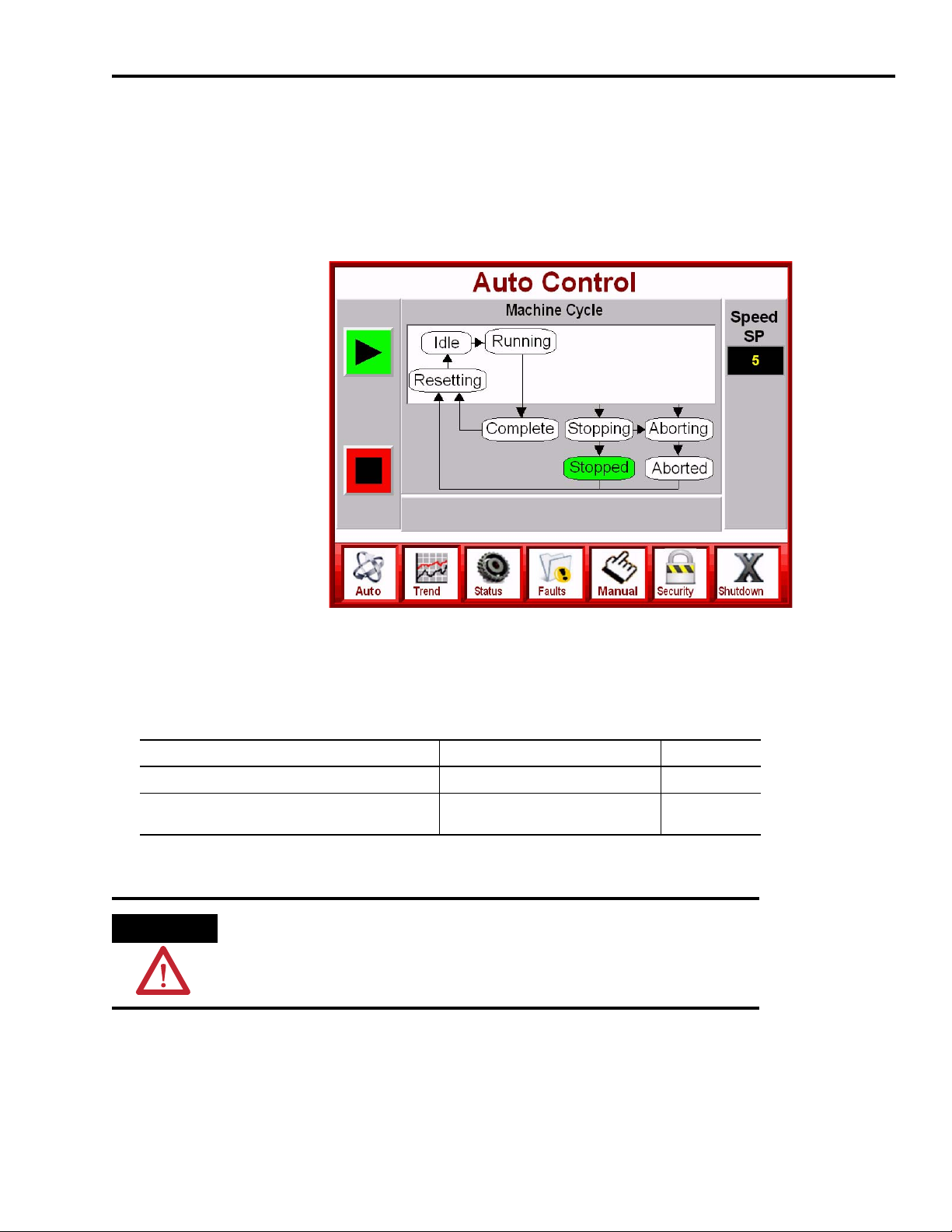
Motion System Application Guide Chapter 7
Use the Auto Control Display
The Auto Control display lets you start, stop, hold, and restart the motion system. The state
machine section provides the status of the current motion system phase state.
Press Auto on the Application Navigation Bar. The Auto Control display opens.
Start Button
Stop Button
Application
Navigation Bar
Start and Run State Actions
Follow these steps to start your motion system and proceed to Run state.
If System Status Then
The Release Manual Control button is flashing Manual control was not released. Go to step 1.
The (green) Stopped state moves to Resetting and
then to Idle
1. Press Release Manual Control to release manual control.
ATTENTION
Pressing Start will cause the system to jog.
Do not press Start if motion will cause personal injury or damage to
equipment.
Your system is ready to start. Go to step 2.
Publication IASIMP-QS011B-EN-P — January 2009 89
Page 90
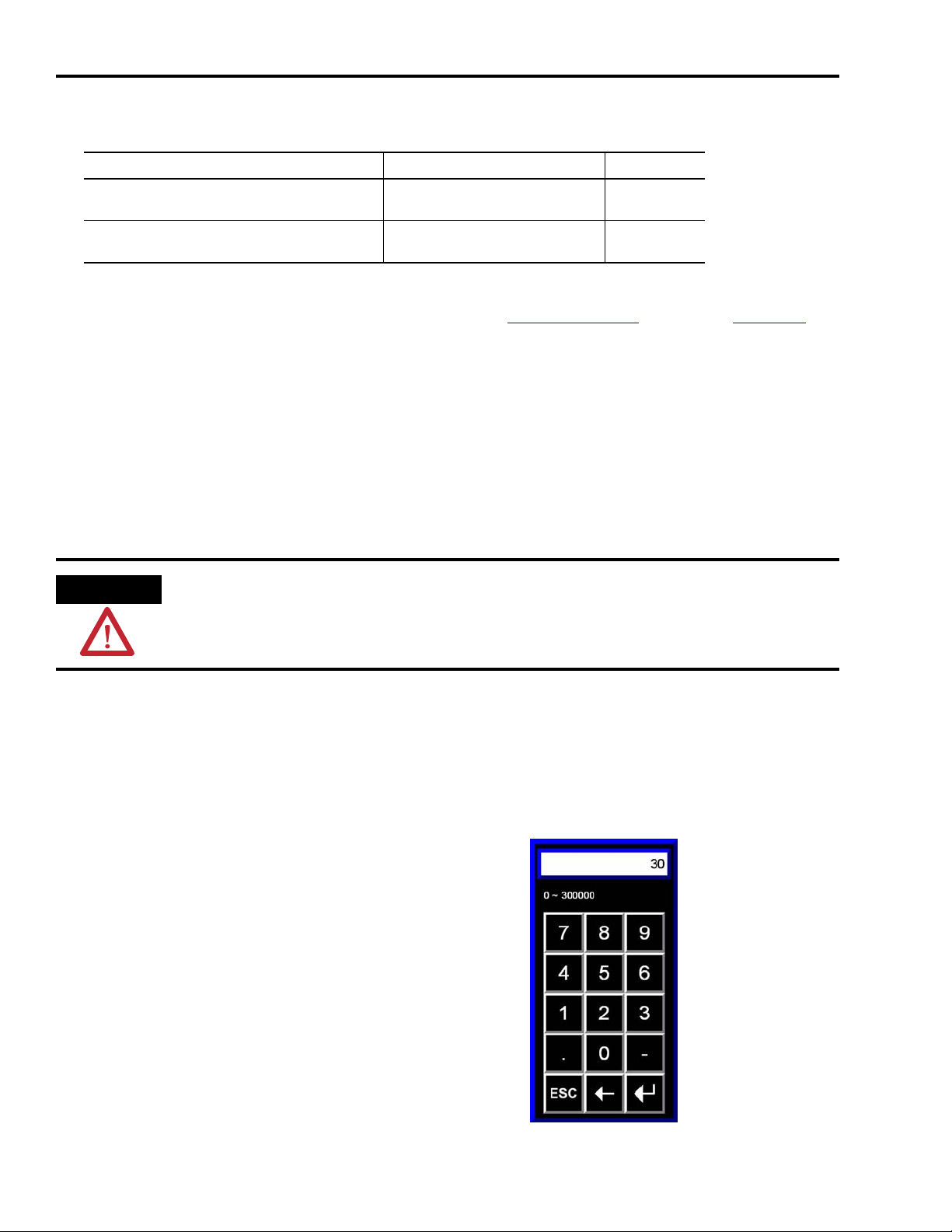
Chapter 7 Motion System Application Guide
2. Press Start.
If System Status Then
The (green) Stopped state moves to Resetting and
then to Aborted
The (green) Stopped state moves to Resetting and
then to Idle
The system failed to reset. Go to step 3.
Your system is ready to start. Go to step 4.
3. Check for power to drives, verify that you have provided a Drive Enable input to each of the
drives and try the Start command again. Refer to the Troubleshooting section on page 115 for
additional assistance.
4. Press Start again.
Stop State Actions
To stop your motion system, press Stop.
The state moves (green) from Running to Stopping and then to Stop.
ATTENTION
The Start and Stop buttons on your PanelView Plus terminal display do not replace a hardwired
start/stop control circuit for safety purposes. Your motion system should also have an emergency
start/stop control circuit.
Adjust the Speed
Follow these steps to adjust the relative speed of your motion system.
1. Press Speed.
The numeric keypad opens.
2. Enter a new speed value from the keypad.
3. Press the Enter button.
The keypad closes and motor speed is updated with
the new value.
Enter
button
90 Publication IASIMP-QS011B-EN-P — January 2009
Page 91
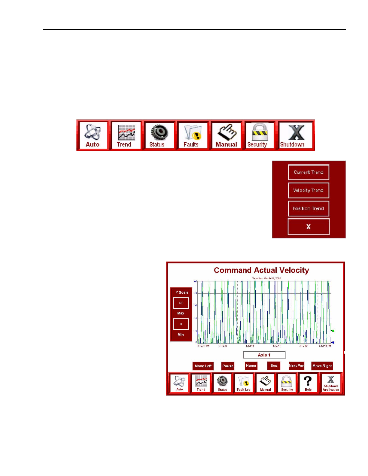
Motion System Application Guide Chapter 7
Use the Trend Display
The Trend display lets you view current, actual velocity, and actual position trends of your
motion system axes over time.
Follow these steps to view torque feedback, actual velocity, and actual position trends.
1. Press Trend on the Application Navigation Bar.
The trend selector display opens.
2. Select your trend of choice.
The trend display opens.
The Command Actual Velocity trend (shown) operates similarly to
the other trend displays.
3. Press Axis 1 to view trends of other axes. (Refer to Change the Axis Selection on page 88.)
The Axis Selection display opens
and lets you change the axis trend
to view as shown in the Manual
Control section.
In this example, two axes are
trended, but based on your axis
configuration, other axes can also
be viewed.
4. Press Y-Scale Min or Max to
change values.
The numeric keypad opens. (Refer
to Adjust the Speed
view the keypad.)
on page 90 to
5. Enter a new value and press Enter.
The keypad closes and the Y-Scale (Min or Max) is updated with the new value.
Publication IASIMP-QS011B-EN-P — January 2009 91
Page 92

Chapter 7 Motion System Application Guide
Use the Axis Status Display
The Axis Status display shows general motion, axis, and drive status, and faults.
Follow these steps to view status and fault indicators and to select the axis.
1. Press Status on the Application Navigation Bar. The Axis Status display opens.
2. Select a system Status or Fault
category from the axis (left)
window.
The green indicator confirms your
status/faults selection.
3. Monitor the status or fault
indicators (right side and below.)
In this example, Axis Status
indicators are shown. Servo
Enabled, Servo Faulted, and
Network Fault status indicators are
always present.
Axis Status, Drive Status, Axis Faults, and Drive Faults indicators show the corresponding
status/faults of the axis displayed on the Axis Select button.
The ON/OFF and Faulted/Non-Faulted states are described in the tables below.
Status Indicators
Status Indicators ON State OFF State Fault Indicators
Axis Status
Green Grey
Drive Status Drive Faults
Module Faults
Faulted
State
Red Grey
Non-faulted
State
4. Press Axis Select Axis (1) to select another axis for status and fault viewing. (Refer to Change
the Axis Selection on page 88 for axis selection operation.)
92 Publication IASIMP-QS011B-EN-P — January 2009
Page 93
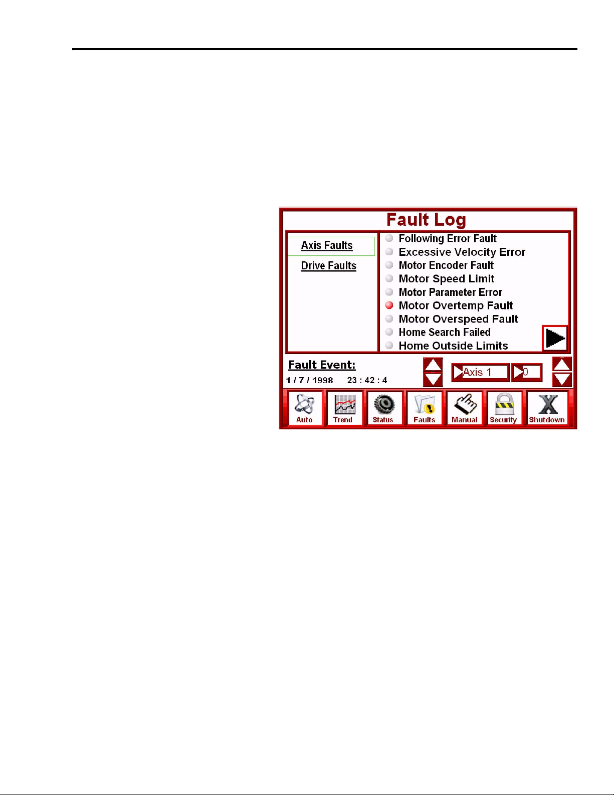
Motion System Application Guide Chapter 7
Use the Fault Log Display
The Fault Log display lets you monitor and/or log motion group, module, axis, or drive fault
events.
Follow these steps to monitor and/or log fault events.
1. Press Fault on the Application Navigation Bar.
The Fault Log display opens.
2. Select a system Fault category
from the Fault window (left).
The green indicator confirms your
fault selection.
3. Monitor the Fault Indicators
(right).
In this example, Axis Fault
indicators are shown. Red
indicators represent a faulted state.
Grey indicators represent a
non-faulted state.
The Logix controller stores the last 50 fault events for each axis. A fault event is triggered by
any non-fault to fault transition for any given axis. The 50 faults are stored on a first-in/
first-out basis.
The indicators displayed correspond to the selected axis.
4. Press the up/down arrows to the left of the selected axis to change the axis.
5. Press the up/down arrows to the right of the selected axis to change the fault event.
Fault events number 0…49. When the fault event number changes, the fault event date/time
and indicators also change.
Publication IASIMP-QS011B-EN-P — January 2009 93
Page 94
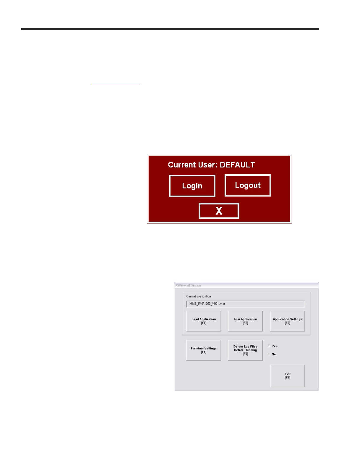
Chapter 7 Motion System Application Guide
Use the Security Display
The security feature of FactoryTalk View ME lets you limit privileges to the individuals that use
the FactoryTalk View ME application. Refer to FactoryTalk View Machine Edition User’s Guide,
Volume 1, publication VIEWME-UM004, for more information.
The security display adds login and logout functions to the application. User names and
passwords have not been setup in the FactoryTalk View ME application files, but using
FactoryTalk ViewStudio software, you can edit the base application files to add user names and
passwords for your specific needs.
1. Press Security on the Application Navigation Bar.
The Current User window opens.
2. Press Login.
Shut Down Application
To shut down the application, press Shutdown Application on the Application Navigation Bar.
The FactoryTalk View ME application shuts down.
The PanelView Plus terminal returns to the
FactoryTalk View ME Station display.
94 Publication IASIMP-QS011B-EN-P — January 2009
Page 95
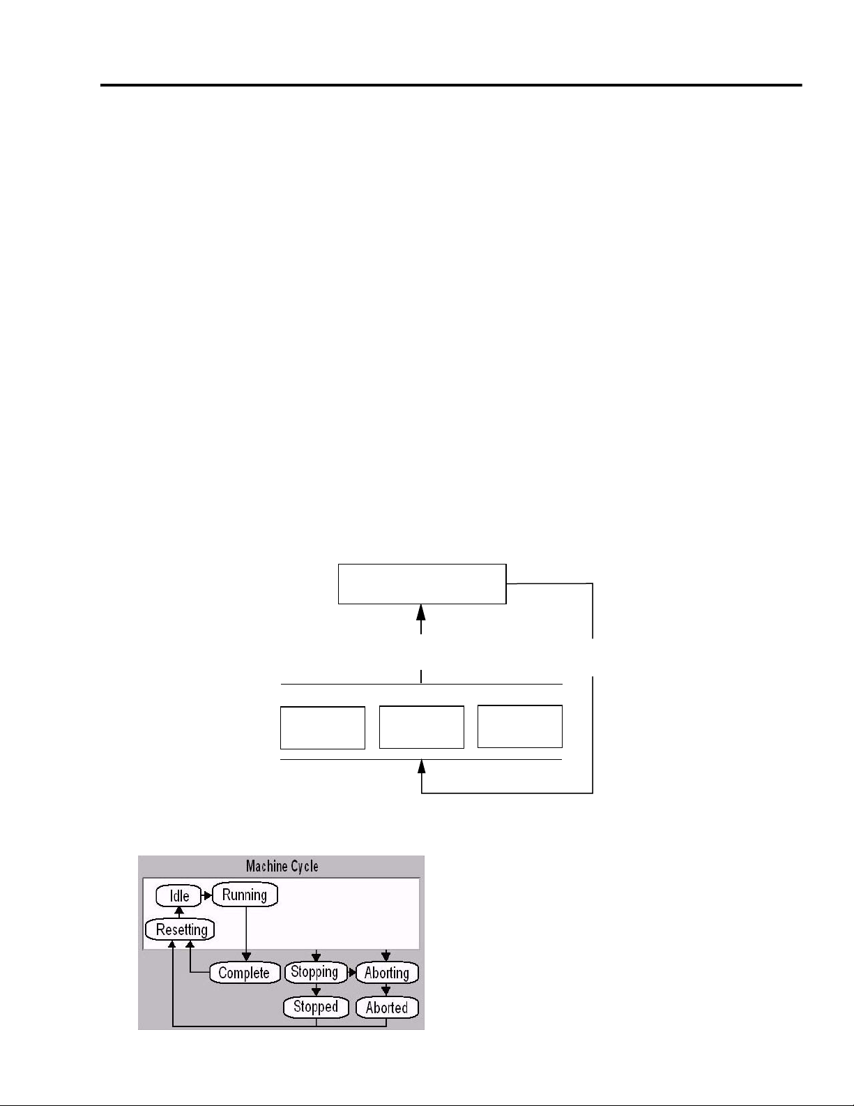
Appendix
A
CompactLogix Base Program Overview
The pre-configured CompactLogix program is a Rockwell Automation solution that helps
machine builders and end users streamline their motion control programming. This application
template provides a basis for using motion control, understanding the principles of state
programming, and creating a consistent program structure.
The CompactLogix program template does the following:
• Incorporates a simple state machine sequencing programming.
• Provides a base structure, making it easier to write, use, and manage the code for your
machine or equipment.
• Streamlines the development of application programs.
• Can be optionally sequenced with PhaseManager for S-88 compatibility (L3x only), but
PhaseManager is not required.
Basic Program Flow
P01_AXIS_01 P01_AXIS_02 Pxx_AXIS_xx
Automatic Machine Cycle Diagram
Main Machine Control
P00_Control
Machine
Status
Axis/Equipment Control
...
Axis
Command
Publication IASIMP-QS011B-EN-P — January 2009 95
Page 96

Appendix A CompactLogix Base Program Overview
TIP
If you are familiar with the full S-88 functionality of the Kinetix Accelerator Toolkit sample code,
note that the CompactLogix Indexing Motion Accelerator Toolkit provides a reduced set of
functionality. It does not use PhaseManager.
Main Machine Control (P00_Control)
All machine control is initiated from the P00_Control program within the T00_Main task. The
sequencing of the machine state (Resetting, Idle, Running, Stopping, or Stopped) is handled in
routines in this main control program. This is done based on user input from the HMI and
machine conditions.
Main Machine Control Flow
The R03_Commands_AUTO routine controls the automatic cycle of the machine and the
R04_Commands_MANUAL routine controls the manual functions of the servo axes.
96 Publication IASIMP-QS011B-EN-P — January 2009
Page 97

CompactLogix Base Program Overview Appendix A
Overall Program Flow
The automatic cycle and the manual cycle are controlled by a state sequencer. The sequencer has
an index register (for example, AutoCycle.StepIndex) that can only be at one value at a time, so
the states of the machine are unique. The sequencer changes states based on the commands and
conditions of the machine.
In the P00_Control rung example below, if the conditions (not manual, auto cycle idle state, and
user start request) are met, a machine start command is initiated.
Start Command Rung
There is logic in the main machine control P00_Control program for the automatic cycle as well
as manual machine control.
Publication IASIMP-QS011B-EN-P — January 2009 97
Page 98

Appendix A CompactLogix Base Program Overview
Automatic Machine Cycle Commands
The diagram above shows the automatic cycle flow provided in the application template. As the
commands are issued (Reset, Start, Stop, or Abort) by the user or the application logic, the action
items shown inside the Action States are issued from the P00_Control routine to each of the
Pxx_AXIS_xx programs. The actual axis commands (Fault Reset, Enable, Jog, Stop, etc.) exist in
the routines of the Pxx_AXIS_xx programs and not in the P00_Control program.
Command Issued
98 Publication IASIMP-QS011B-EN-P — January 2009
Page 99

CompactLogix Base Program Overview Appendix A
Action Taken
Should any of these command action states fail to complete, the application template issues an
abort command which stops the running cycle and disables the servo drives.
Publication IASIMP-QS011B-EN-P — January 2009 99
Page 100
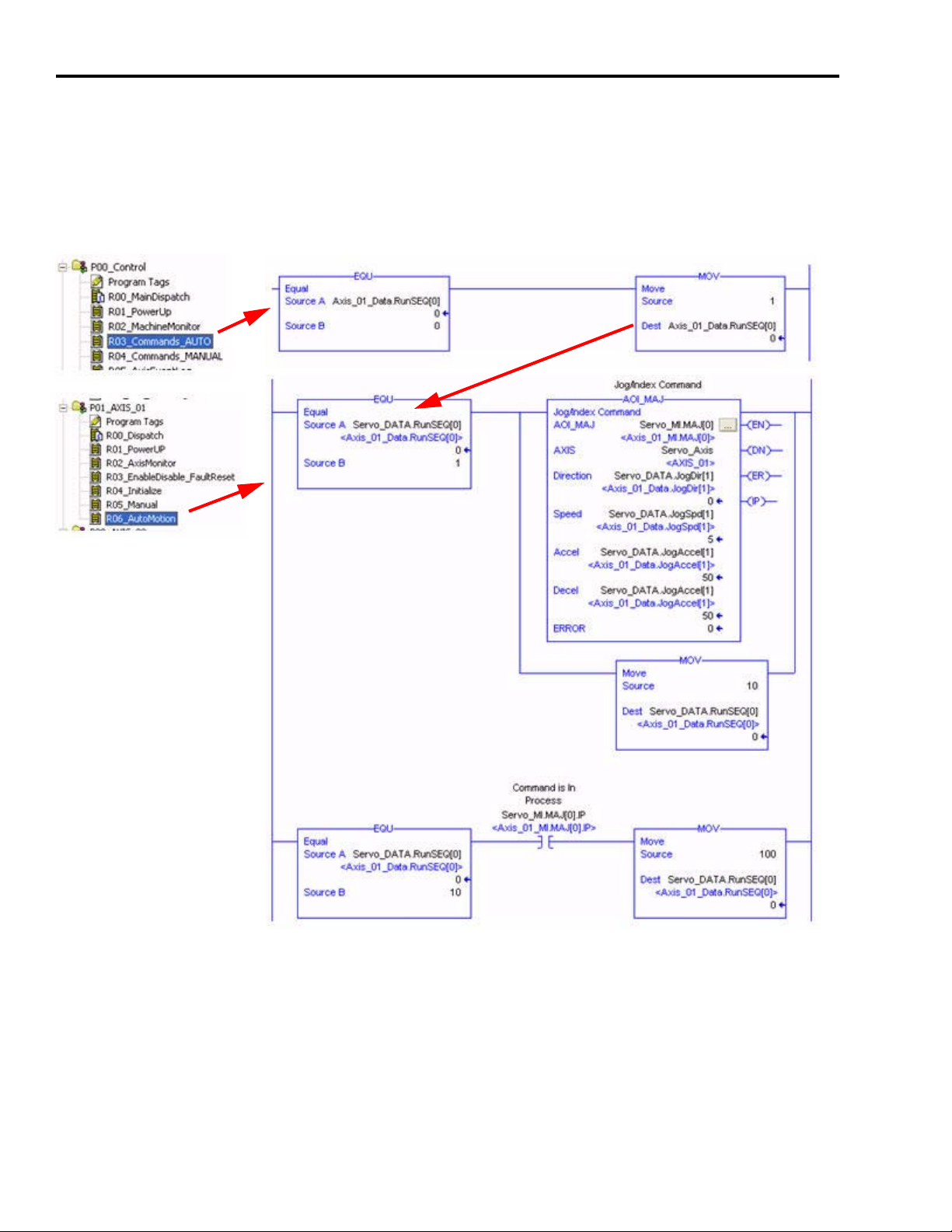
Appendix A CompactLogix Base Program Overview
Axis/Equipment Control
The individual axis actions are controlled based on the machine state. Any of the states will issue
commands that will initiate actions programmed within routines in the individual axis programs.
In the rungs of code below, within the Auto-Running phase state logic, a sequence word is set to
a value of 1 to initiate a run sequence in P01_AXIS_00…R06_AutoMotion routine.
In this case, a Jog command is issued on AXIS_01.
100 Publication IASIMP-QS011B-EN-P — January 2009
 Loading...