

Page 1

Installation Instructions
ControlNet-to-DeviceNet Linking Device
Catalog Number 1788-CN2DN
Topic Page
Important User Information 2
About the CN2DN Linking Device 7
Parts List 8
Required System Components 9
Install the CN2DN Device 9
Mount the CN2DN Device on a DIN Rail 10
Mount the CN2DN Device on a Panel or Other Fixture 12
Wire a Power Supply to the CN2DN Device 13
Set the Node Addresses and Communication Rate 15
Connect the CN2DN Device to a ControlNet Network 16
Connect the CN2DN Device to a DeviceNet Network 17
Uninstall the CN2DN Linking Device 19
Interpret the LED Indicators 21
Troubleshoot the DeviceNet Network 29
Troubleshoot the ControlNet Network 46
Specifications 47
Additional Resources 51
Publication 1788-IN052D-EN-P - February 2007
Page 2
2 ControlNet-to-DeviceNet Linking Device
Important User Information
Solid state equipment has operational characteristics differing from those of electromechanical
equipment. Safety Guidelines for the Application, Installation and Maintenance of Solid State Controls
(publication SGI-1.1 available from your local Rockwell Automation sales office or online at
http://literature.rockwellautomation.com
equipment and hard-wired electromechanical devices. Because of this difference, and also because of
the wide variety of uses for solid state equipment, all persons responsible for applying this equipment
must satisfy themselves that each intended application of this equipment is acceptable.
In no event will Rockwell Automation, Inc. be responsible or liable for indirect or consequential damages
resulting from the use or application of this equipment.
The examples and diagrams in this manual are included solely for illustrative purposes. Because of the
many variables and requirements associated with any particular installation, Rockwell Automation, Inc.
cannot assume responsibility or liability for actual use based on the examples and diagrams.
No patent liability is assumed by Rockwell Automation, Inc. with respect to use of information, circuits,
equipment, or software described in this manual.
Reproduction of the contents of this manual, in whole or in part, without written permission of Rockwell
Automation, Inc., is prohibited.
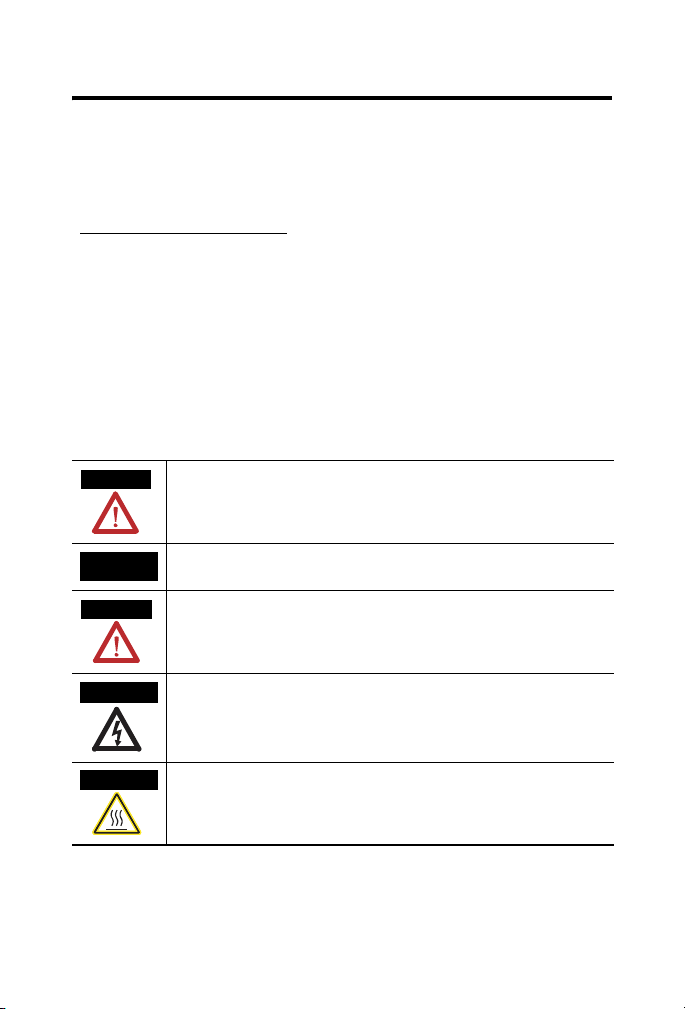
Throughout this manual, when necessary, we use notes to make you aware of safety considerations.
WARNING
Identifies information about practices or circumstances that can cause an explosion in
a hazardous environment, which may lead to personal injury or death, property
damage, or economic loss.
) describes some important differences between solid state
IMPORTANT
ATTENTION
SHOCK HAZARD
BURN HAZARD
Publication
Identifies information that is critical for successful application and understanding of
the product.
Identifies information about practices or circumstances that can lead to personal
injury or death, property damage, or economic loss. Attentions help you to identify a
hazard, avoid a hazard and recognize the consequences.
Labels may be located on or inside the equipment, for example, a drive or motor, to
alert people that dangerous voltage may be present.
Labels may be located on or inside the equipment, for example, a drive or motor, to
alert people that surfaces may be at dangerous temperatures.
1788-IN052D-EN-P - February 2007
Page 3
ControlNet-to-DeviceNet Linking Device 3
T
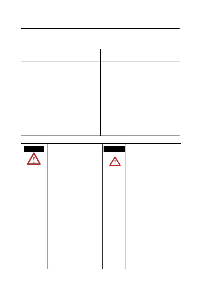
North American Hazardous Location Approval
The following Information applies when operating
this equipment in hazardous locations:
Products marked "CL I, DIV 2, GP A, B, C, D" are
suitable for use in Class I Division 2 Groups A, B,
C, D, Hazardous Locations and nonhazardous
locations only. Each product is supplied with
markings on the rating nameplate indicating the
hazardous location temperature code. When
combining products within a system, the most
adverse temperature code (lowest "T" number)
may be used to help determine the overall
temperature code of the system. Combinations of
equipment in your system are subject to
investigation by the local Authority Having
Jurisdiction at the time of installation.
WARNING
EXPLOSION HAZARD
Do not disconnect equipment
unless power has been removed
or the area is known to be
nonhazardous.
Do not disconnect connections to
this equipment unless power has
been removed or the area is
known to be nonhazardous.
Secure any external connections
that mate to this equipment by
using screws, sliding latches,
threaded connectors, or other
means provided with this product.
Substitution of components may
impair suitability for Class I,
Division 2.
If this product contains batteries,
they must only be changed in an
area known to be nonhazardous.
Informations sur l'utilisation de cet équipement en
environnements dangereux:
Les produits marqués "CL I, DIV 2, GP A, B, C, D"
ne conviennent qu'à une utilisation en
environnements de Classe I Division 2 Groupes A,
B, C, D dangereux et non dangereux. Chaque
produit est livré avec des marquages sur sa plaque
d'identification qui indiquent le code de
température pour les environnements dangereux.
Lorsque plusieurs produits sont combinés dans un
système, le code de température le plus
défavorable (code de température le plus faible)
peut être utilisé pour déterminer le code de
température global du système. Les combinaisons
d'équipements dans le système sont sujettes à
inspection par les autorités locales qualifiées au
moment de l'installation.
AVERTISSEMEN
Publication
RISQUE D'EXPLOSION
Couper le courant ou s'assurer
que l'environnement est classé
non dangereux avant de
débrancher l'équipement.
Couper le courant ou s'assurer
que l'environnement est classé
non dangereux avant de
débrancher les connecteurs. Fixer
tous les connecteurs externes
reliés à cet équipement à l'aide
de vis, loquets coulissants,
connecteurs filetés ou autres
moyens fournis avec ce produit.
La substitution de composants
peut rendre cet équipement
inadapté à une utilisation en
environnement de Classe I,
Division 2.
S'assurer que l'environnement est
classé non dangereux avant de
changer les piles.
1788-IN052D-EN-P - February 2007
Page 4

4 ControlNet-to-DeviceNet Linking Device
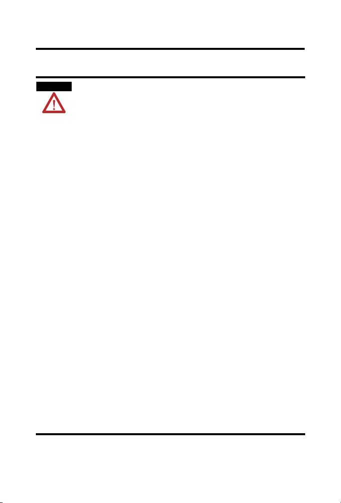
European Hazardous Location Approval
European Zone 2 Certification (The following applies when the
product bears the EEx Marking)
This equipment is intended for use in potentially explosive
atmospheres as defined by European Union Directive 94/9/EC.
The LCIE (Laboratoire Central des Industries Electriques) certifies that
this equipment has been found to comply with the Essential Health
and Safety Requirements relating to the design and construction of
Category 3 equipment intended for use in potentially explosive
atmospheres, given in Annex II to this Directive.
Compliance with the Essential Health and Safety Requirements has
been assured by compliance with EN 60079-15.
IMPORTANT
Publication
This equipment is not resistant to sunlight or other sources of UV
radiation.
Equipment of lesser Enclosure Type Rating must be installed in an
enclosure providing at least IP54 protection when applied in Class
I, Zone 2 environments.
This equipment shall be used within its specified ratings defined by
Allen-Bradley.
Provision shall be made to prevent the rated voltage from being
exceeded by transient disturbances of more than 40% when
applied in Class I, Zone 2 environments.
1788-IN052D-EN-P - February 2007
Page 5
Environment and Enclosure
ControlNet-to-DeviceNet Linking Device 5
ATTENTION
This equipment is intended for use in a Pollution Degree 2 industrial
environment, in overvoltage Category II applications (as defined in IEC
publication 60664-1), at altitudes up to 2000 m (1.24 mi) without
derating.
This equipment is considered Group 1, Class A industrial equipment
according to IEC/CISPR Publication 11. Without appropriate
precautions, there may be potential difficulties ensuring
electromagnetic compatibility in other environments due to
conducted as well as radiated disturbance.
This equipment is supplied as open-type equipment. It must be
mounted within an enclosure that is suitably designed for those
specific environmental conditions that will be present and
appropriately designed to prevent personal injury resulting from
accessibility to live parts. The enclosure must have suitable
flame-retardant properties to prevent or minimize the spread of flame,
complying with a flame spread rating of 5VA, V2, V1, V0 (or
equivalent) if non-metallic. The interior of the enclosure must be
accessible only by the use of a tool. Subsequent sections of this
publication may contain additional information regarding specific
enclosure type ratings that are required to comply with certain
product safety certifications.
Besides this publication, see:
Industrial Automation Wiring and Grounding Guidelines, publication
1770-4.1.
NEMA Standards publication 250 and IEC publication 60529, as
applicable, for explanations of the degrees of protection provided by
different types of enclosure.
Publication
1788-IN052D-EN-P - February 2007
Page 6

6 ControlNet-to-DeviceNet Linking Device
Prevent Electrostatic Discharge
ATTENTION
This equipment is sensitive to electrostatic discharge, which can
cause internal damage and affect normal operation. Follow these
guidelines when you handle this equipment:
• Touch a grounded object to discharge potential static.
• Wear an approved grounding wriststrap.
• Do not touch connectors or pins on component boards.
• Do not touch circuit components inside the equipment.
• Use a static-safe workstation, if available.
• Store the equipment in appropriate static-safe packaging when
not in use.
Publication
1788-IN052D-EN-P - February 2007
Page 7
ControlNet-to-DeviceNet Linking Device 7
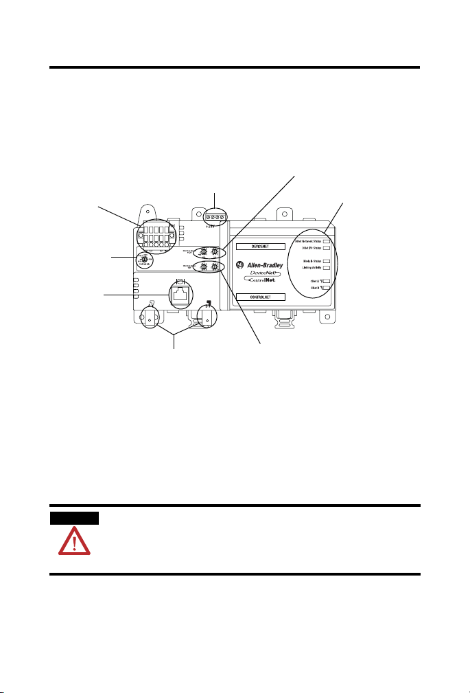
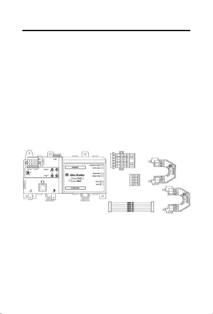
About the CN2DN Linking Device
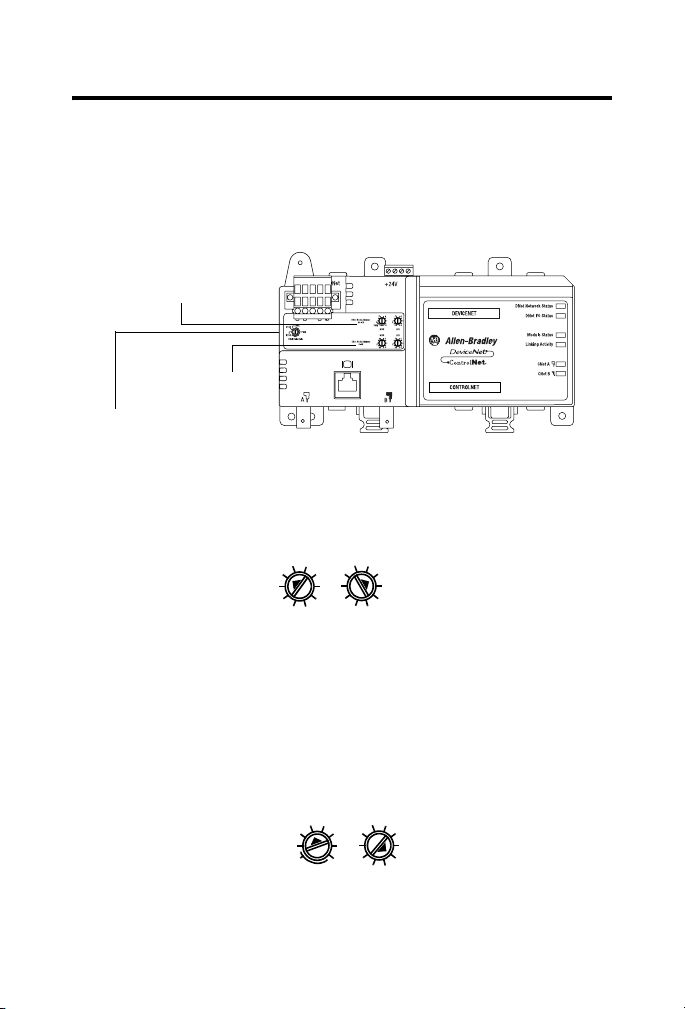
Use following graphic to identify the components of your
ControlNet-to-DeviceNet linking device.
CN2DN Linking Device Components
Power Port and
Connector
DeviceNet Port and
Connector
DeviceNet Baud
Rate Switch
Network
Access Port
DeviceNet Node Address
Switches
LED Indicators
ControlNet Connection Ports
ControlNet Node Address
Switches
The DeviceNet connection port is located on the top left corner of the
device. See the section titled Connect the CN2DN Device to a
DeviceNet Network for more information.
Rotary switches to set the ControlNet node address, DeviceNet node
address, and the DeviceNet communication rate are located just
below the power and DeviceNet ports. See the section titled Uninstall
the CN2DN Linking Device for more information.
ATTENTION
The Network Access Port (NAP) is intended for local temporary
programming use only. It is not for permanent connection.
Use only specified NAP cable to the network.
Located below the rotary switches, the ControlNet network access
port allows for easy access of the ControlNet network using a laptop
and 1784-PCC card. Use 1786-CP connection cable to access the
ControlNet network using the NAP port.
Publication
1788-IN052D-EN-P - February 2007
Page 8
8 ControlNet-to-DeviceNet Linking Device
Two ControlNet connection ports are located on the bottom left side
of the device and provide the availability to connect a redundant
network. See the section titled Connect the CN2DN Device to a
ControlNet Network on page 16 for more information.
For more information about the power port and connector, see the
section titled Wire a Power Supply to the CN2DN Device on page 13.
For more information about the LED indicators, see the section titled
Interpret the LED Indicators on page 21.
Parts List
The following parts are included with the 1788-CN2DN linking
device.
1788-CN2DN Parts
1788-CN2DN
• One 1788-CN2CN linking device
• One power input connector
• One DeviceNet 10-pin linear connector
• Five 121 Ω resistors
• Two end anchors
Publication
1788-IN052D-EN-P - February 2007
DeviceNet
Connector
Power
Connector
121 Ω Resistors
End Anchors
31670-M
Page 9

ControlNet-to-DeviceNet Linking Device 9
Required System Components
In order to install your 1788-CN2DN device, you will need the
following system components.
• A 24V dc power supply
and
• A securely installed zinc-plated, yellow-chrome steel, DIN rail,
panel, or other suitable fixture.
Install the CN2DN Device
Complete the following tasks to install the CN2DN Linking Device.
• Mount the CN2DN Device on a DIN Rail
• Mount the CN2DN Device on a Panel or Other Fixture
• Wire a Power Supply to the CN2DN Device
• Uninstall the CN2DN Linking Device
• Set the Node Addresses and Communication Rate
• Connect the CN2DN Device to a ControlNet Network
• Connect the CN2DN Device to a DeviceNet Network
Publication
1788-IN052D-EN-P - February 2007
Page 10
10 ControlNet-to-DeviceNet Linking Device
Mount the CN2DN Device on a DIN Rail
ATTENTION
This product is grounded through the DIN rail to chassis ground. Use
zinc plated yellow-chromate steel DIN rail to assure proper grounding.
The use of other DIN rail materials (for example, aluminum and
plastic) that can corrode, oxidize, or are poor conductors, can result in
improper or intermittent grounding. Secure DIN rail to mounting
surface approximately every 200 mm (7.87 in.) and use end-anchors
appropriately.
IMPORTANT
The DIN rail must be properly grounded. See publication Industrial
Automation Wiring and Grounding Guidelines, publication 1770-4.1
for more information about DIN rail grounding.
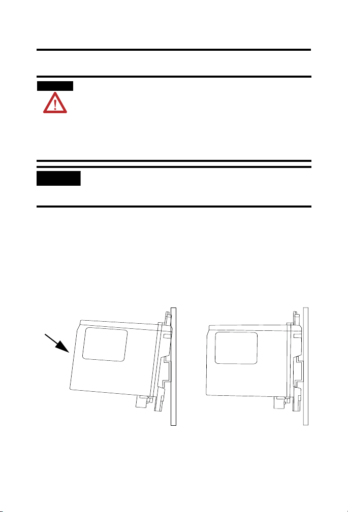
Complete the following steps to mount the CN2DN device on a DIN
rail.
1. Align the CN2DN device over the DIN rail.
2. Press the CN2DN device onto the DIN rail until the DIN rail
latches lock the linking device in place.
Press Forward
and Down
Publication
1788-IN052D-EN-P - February 2007
Page 11
ControlNet-to-DeviceNet Linking Device 11
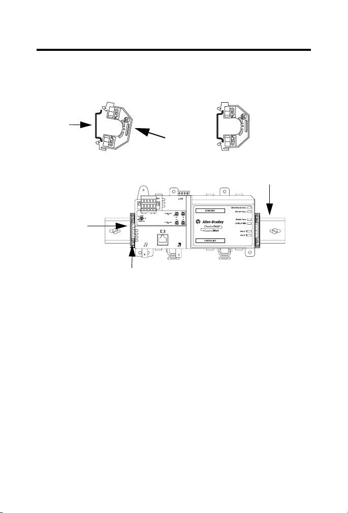
3. Clip each of the end anchors onto the DIN rail next to the
CN2DN device.
End Anchor onto DIN Rail
DIN Rail
Clip On
End Anchors Next to Device
Slide the Anchor
Against the
CN2DN Device
Tighten the Clamping Screws
Grounded DIN Rail
4. Slide each anchor against the device and tighten the screws on
the front of the end anchor.
Publication
1788-IN052D-EN-P - February 2007
Page 12
12 ControlNet-to-DeviceNet Linking Device
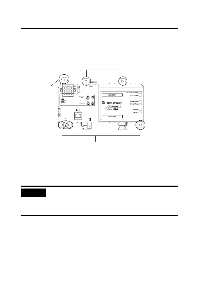
5. If you are mounting your CN2DN device in a high-vibration
area, insert screws (not included) into the holes of the
mounting tabs and tighten so that the screws are firmly
anchored into the panel behind the device.
Mount Tabs (Optional Use)
Ground Connection
(Optional) - For use if
DIN rail or panel is
not grounded. If
used, this tab must
be properly
connected to the
earth ground.
Mount Tabs (Optional Use)
You have completed mounting your CN2DN device on a DIN rail.
Mount the CN2DN Device on a Panel or Other Fixture
IMPORTANT
If mounting the CN2DN device to a panel, ensure that the panel is
conductive metal and properly grounded. Paint or other coatings
should be sanded from the panel to ensure the CN2DN device
makes sufficient conductive contact with the panel.
To mount the CN2DN device on a panel or other suitable fixture,
insert five screws (not included) through the module’s mounting tabs
and into the panel or fixture behind the module. Use screws long
enough to penetrate the panel or fixture for a secure mount.
Publication
1788-IN052D-EN-P - February 2007
Page 13
ControlNet-to-DeviceNet Linking Device 13
Wire a Power Supply to the CN2DN Device
ATTENTION
To comply with the CE Low Voltage Directive (LVD), power to this
equipment and DeviceNet must be powered from a source compliant
with the following: Safety Extra Low Voltage (SELV) or Protected Extra
Low Voltage (PELV).
To comply with UL restrictions, DeviceNet must be powered from a
source compliant with the following: Class 2 or Limited
Voltage/Current.
ATTENTION
24V dc power connection wiring length must be less than 10 m (32.81
ft).
The CN2DN device requires 18...30V dc input power provided by a
power supply that is separate from the DeviceNet network power
supply.
Complete the following steps to wire the power supply to the CN2DN
linking device.
1. Disconnect power to the power supply.
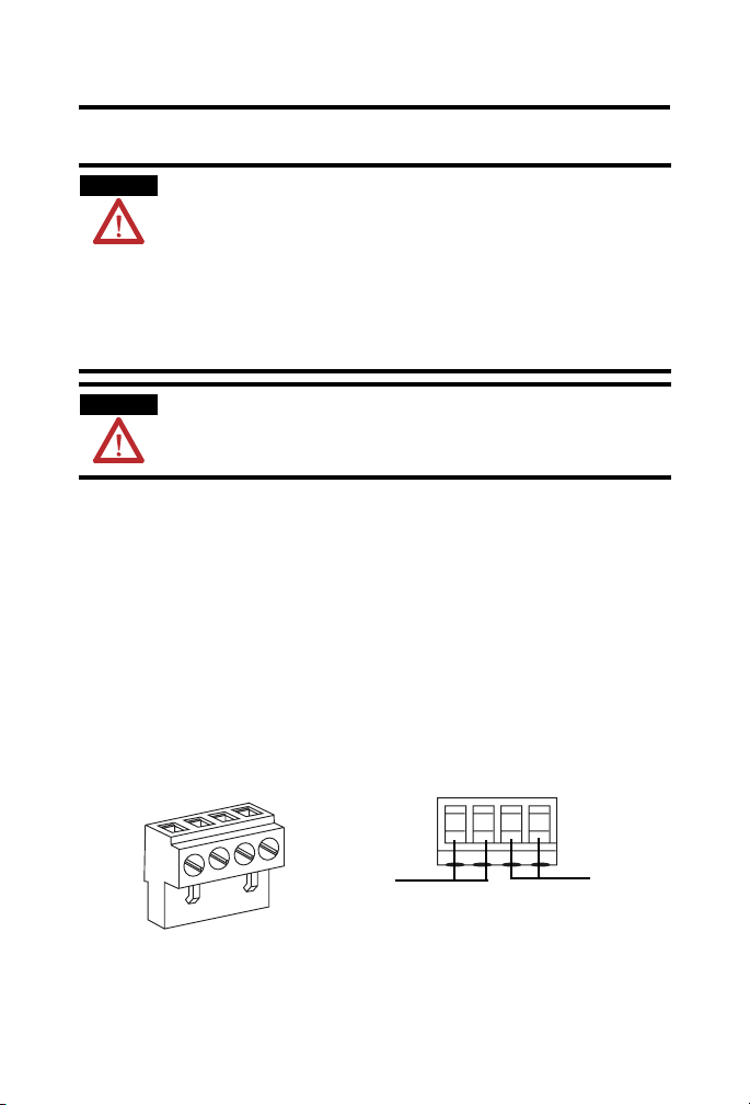
2. Locate the orange power connector.
Power Connector
Power Connector, Top
+ - + -
+ -
Power Supply
Wiring
Terminals
Publication
Daisy Chain
to Device
Wiring
Ter mi na ls
(Optional Use)
1788-IN052D-EN-P - February 2007
Page 14

14 ControlNet-to-DeviceNet Linking Device
3. Loosen the two left-most terminal screws of the power
connector.
IMPORTANT
Do not connect more than two wires to any terminal.
4. Insert the bare power supply wire ends into the left-side
terminals of the power supply connector using the diagram as
a guide.
5. Tighten the two left terminal screws using 0.6 Nm (7 in-lb)
torque.
IMPORTANT
The power supply connector must be inserted into the CN2DN
device for power to reach any devices daisy chained from the
CN2DN power supply connector.
6. If you choose to connect another device to the power supply
connector of the CN2DN device, loosen the two terminal
screws on the right side of the connector.
7. Insert the bare device power wire ends into the two right
terminals using the diagram as a reference.
8. Tighten the two right terminal screws using 0.6 Nm (7 in-lb)
torque.
9. Insert the power supply connector into the power supply
connector port.
10. Reapply power to the dc power supply.
The LED indicators on the right side of the CN2DN device will
flash red to indicate power has been connected.
You have completed wiring the power supply to the CN2DN device.
Publication
1788-IN052D-EN-P - February 2007
Page 15
ControlNet-to-DeviceNet Linking Device 15
Set the Node Addresses and Communication Rate
Complete the following steps to set the node addresses using the
switches on the front of the CN2DN device.
CN2DN Device Switches
DeviceNet
Address
Switches
ControlNet
DeviceNet Baud
Rate Switch
1. To set the DeviceNet node address, use a small flat-head
screwdriver to turn the arrows of the switches towards the
desired node numbers.
Address
Switches
DeviceNet switches shown set to node 14.
2
0
8
2
4
0
6
8
MSD LSD
4
6
2. To set the DeviceNet communication rate, turn the DeviceNet
baud rate switch to the communication rate your DeviceNet
network is configured to, for example 125 K, 250 K, or 500 K.
3. To set the ControlNet node address, use a small Phillips-head
screwdriver to turn the arrows of the switches towards the
desired node numbers.
ControlNet switches shown set to node 26.
2
0
PGM
2
4
0
6
8
MSD LSD
4
6
You have completed setting the ControlNet and DeviceNet node
addresses and communication rate.
Publication
1788-IN052D-EN-P - February 2007
Page 16
16 ControlNet-to-DeviceNet Linking Device
Connect the CN2DN Device to a ControlNet Network
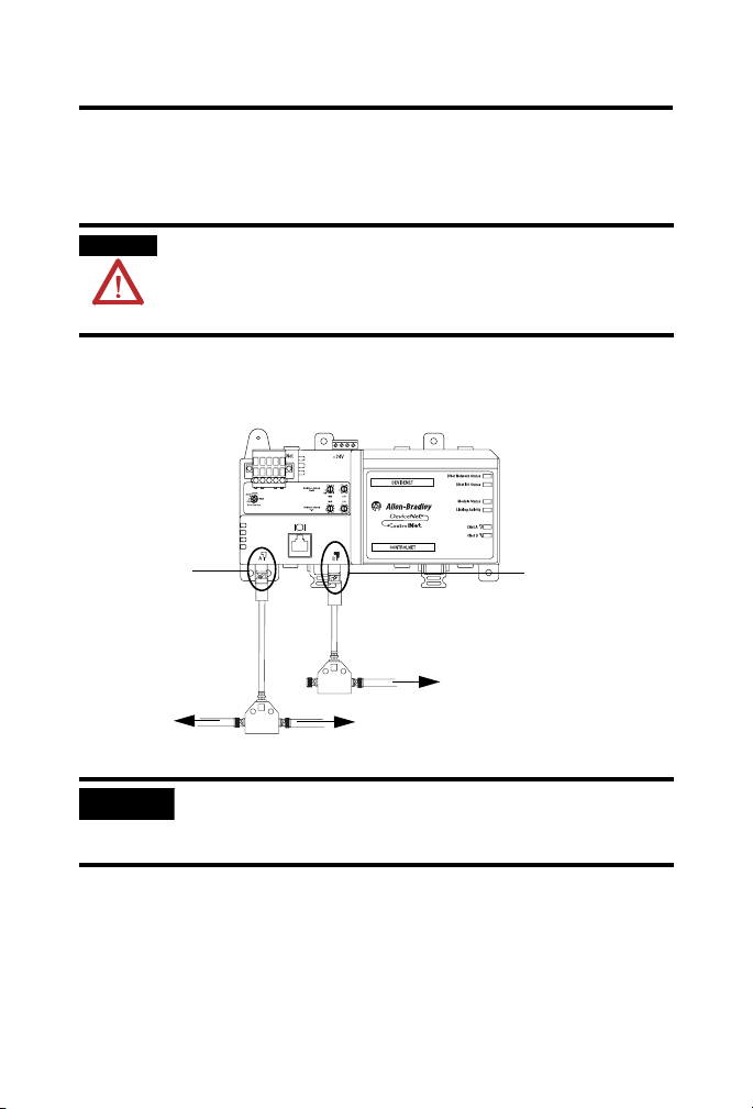
Complete the following steps to connect your CN2DN linking device
to the ControlNet network.
WARNING
If you connect or disconnect the communications cable with power
applied to this module or any device on the network, an electrical arc
can occur. This could cause an explosion in hazardous location
installations.
1. Attach the BNC connector of the ControlNet cable to
ControlNet port A.
If using redundant
Attach the BNC
Connector of the
ControlNet tap to
ControlNet port A.
Main ControlNet
Network Cable
IMPORTANT
Redundant ControlNet
Network Cable (Optional)
Main ControlNet
Network Cable
Do not connect more than one ControlNet network to the CN2DN
cabling, attach the BNC
connector of the
ControlNet tap to
ControlNet port B.
device at a time. Connecting the CN2DN device to two networks at
one time will cause erratic behavior of the CN2DN device.
2. If you are connecting to redundant media, attach the BNC
connector of the other ControlNet cable to ControlNet port B.
The CN2DN linking device is now connected to the ControlNet
network.
Publication
1788-IN052D-EN-P - February 2007
Page 17

ControlNet-to-DeviceNet Linking Device 17
Connect the CN2DN Device to a DeviceNet Network
WARNING
If you connect or disconnect the communications cable with power
applied to this module or any device on the network, an electrical arc
can occur. This could cause an explosion in hazardous location
installations.
Complete the following steps to connect your CN2DN device to a
DeviceNet network using the 10-pin linear connector included with
the CN2DN device.
You may also use the following DeviceNet connectors not included
with the device.
• 5-pin linear connector (1799-DNETSCON or 1799-DNETCON)
• 5-pin linear to micro connector (1799-DNC5MMS)
Consult the DeviceNet Media Design and Installation Guide,
publication DNET-UM072, for more information about using the
connectors not included with the 1788-CN2DN linking device.
1. Strip 65 mm (2.6 in.) to 75 mm (2.96 in.) of the outer jacket
from the end of the DeviceNet cable, leaving no more than 6.4
mm (0.25 in.) of the braided shield exposed.
Braided Shield
6.4 mm
(0.25 in.)
Jacket
65 mm (2.6 in.)
Publication
1788-IN052D-EN-P - February 2007
Page 18

18 ControlNet-to-DeviceNet Linking Device
2. Wrap the end of the cable with 38 mm (1.5 in.) of shrink wrap,
covering part of the exposed conductors and part of the trunk
line insulation.
38 mm
Jacket
(1.5 in.)
Shrink Wrap
41841
3. Strip 8.1 mm (0.32 in.) of the insulation from the end of each
of the colored insulated conductors.
Jacket
Shrink Wrap
8.1 mm
(0.32 in.)
41842
4. Insert each colored conductor into the matching color-coded
terminal cavity of the open-style connector.
5. If the CN2DN device is the first or last node on the DeviceNet
network, insert an end of a 121 Ω resistor into the blue and
white terminal cavities of the DeviceNet port connector.
Publication
1788-IN052D-EN-P - February 2007
Page 19

ControlNet-to-DeviceNet Linking Device 19
The resistor should bridge the blue and white terminal
cavities.
121 Ω
Resistor
Black
Blue
Bare or Shield
Red
White
41827
6. Tighten all of the terminal screws using 0.6 Nm (7 in-lb)
torque.
You have completed connecting to the DeviceNet network.
Uninstall the CN2DN Linking Device
Complete the following steps to uninstall the CN2DN linking device.
1. Remove power from the CN2DN device.
2. Disconnect the power, DeviceNet, and ControlNet connectors.
3. If end anchors are in place, remove by loosening the screws
and unclipping the anchor from the DIN rail.
Publication
1788-IN052D-EN-P - February 2007
Page 20

20 ControlNet-to-DeviceNet Linking Device
4. To remove the CN2DN linking device from the DIN rail, pull
down on the two latches at the bottom of the device while
pulling the CN2DN device away from the DIN rail.
Pull down on DIN rail latches.
You may need to insert a flat-head screwdriver between the
DIN rail latch and the tab that locks the latch into place in
order to remove the device.
Publication
1788-IN052D-EN-P - February 2007
Page 21

ControlNet-to-DeviceNet Linking Device 21
Interpret the LED Indicators
Use the LED indicators on the CN2DN linking device to monitor the
following:
• Module Status
• Linking Activity Status
• DeviceNet Network Status
• ControlNet Network Status
CN2DN Device LED Indicators
DeviceNet Network
Status Indicators
Module Status and
Linking Activity
Status Indicators
ControlNet Status
Indicators
Publication
1788-IN052D-EN-P - February 2007
Page 22

22 ControlNet-to-DeviceNet Linking Device
Module Status
Use the following table to interpret your Module Status LED
indicators and determine if corrective action is necessary.
Module Status Indicator
LED Indicator Device Status Recommended Action
Off No power to device. A. Verify that the power supply is
functioning properly.
B. Cycle power supply.
C. Remove power and check input power
wiring. Reapply power.
D. Replace the CN2DN linking device.
Publication
1788-IN052D-EN-P - February 2007
Page 23

ControlNet-to-DeviceNet Linking Device 23
Module Status Indicator
LED Indicator Device Status Recommended Action
Green, flashing The CN2DN device is
functioning but not
communicating with
devices.
Green, steady Fully operational. The
CN2DN device is
communicating with
all configured
DeviceNet nodes or
there are no
configured devices.
Red, flashing The linking device is
not communicating
with one or more
modules.
Red, steady Unrecoverable
communication fault.
Use RSNetworx software to configure the
CN2DN device. See Additional Resources
for publications with more information
about configuring the CN2DN device.
None. The device has passed self-tests and
is functioning properly if devices have been
configured.
A. Verify that DeviceNet switches are not
set at PGM.
B. Verify that connected devices are
functioning properly.
C. Verify that devices have been
configured properly.
See Additional Resources for publications
with more information about configuring
the CN2DN device.
A. Verify that the CN2DN device has been
assigned a unique node address during
configuration.
B. Verify that all devices are set at the
same baud rate.
C. Cycle CN2DN power.
D. Replace the CN2DN device.
Publication
1788-IN052D-EN-P - February 2007
Page 24

24 ControlNet-to-DeviceNet Linking Device
Linking Activity Status
The Linking Activity LED indicator displays the status of
communication between the DeviceNet and ControlNet networks as
well as the amount of traffic.
Use the following table to interpret the Linking Activity LED indicator.
Linking Activity LED Indicator
LED Indicator Linking Activity Status
Off No network traffic is occurring between the ControlNet to
DeviceNet networks. I/O traffic may be present.
Green, flashing ControlNet to DeviceNet (non-I/O) communication traffic
present (flash rate indicates amount of traffic).
Red and Green, flashing Module is running boot code only (used for FLASH upgrades).
Publication
1788-IN052D-EN-P - February 2007
Page 25

ControlNet-to-DeviceNet Linking Device 25
ControlNet Network Status
The CNet A and CNet B LED indicators display the status of the
ControlNet network and individual channels.
The ControlNet network may recognize more than one network
status a time. If more than one status is present, the CN2DN linking
device will display the highest priority status.
Use the following table to interpret the ControlNet LED indicators.
ControlNet LED Indicators, CNet A and CNet B
LED Indicator State LED View Priority
Off Both CNet A
and CNet B1 (highest
Red, steady Both CNet A
Red and green,
alternating
Red, alternating Both CNet A
Off One, CNet A
Red and green, flashing One, CNet A
Red, flashing One, CNet A
Green, flashing One, CNet A
Green, steady One, CNet A
and CNet B
Both CNet A
and CNet B
and CNet B
or CNet B
or CNet B
or CNet B
or CNet B
or CNet B9 (lowest)
Level
priority)
2 No ControlNet network found.
3 Device self-testing.
4 Incorrect ControlNet node
5 ControlNet channel disabled or not
6 Incorrect ControlNet network
7 No data received from network.
8 Temporary channel error or
ControlNet Network Status
No power.
configuration.
supported.
configuration.
listen-only channel.
Normal network operation.
Publication
1788-IN052D-EN-P - February 2007
Page 26

26 ControlNet-to-DeviceNet Linking Device
DeviceNet Network Status
The DeviceNet network indicators, DNet Network Status and DNet
I/O Status, indicate the state of the DeviceNet network and the state
of DeviceNet I/O modules.
Use the following tables to interpret your DeviceNet LED indicators
located at the top right corner of the CN2DN device.
DNet Network Status Indicator
LED Indicator DeviceNet Network
Status
Off No DeviceNet connection. If a DeviceNet connection has been
Green, flashing DeviceNet network found,
not communicating with
devices.
Recommended Action
made:
A. Verify that the DeviceNet
network is powered.
B. Check DeviceNet cables and
connections.
If devices should be communicating:
A. Check DeviceNet cables and
connections.
B. Verify that all devices on the
DeviceNet network are
functioning properly.
Publication
1788-IN052D-EN-P - February 2007
Page 27

DNet Network Status Indicator
ControlNet-to-DeviceNet Linking Device 27
LED Indicator DeviceNet Network
Status
Green, steady One or more devices
connected and
communicating.
Red, flashing One or more connections
timed-out.
Red, steady Communication error (bus
off condition).
Recommended Action
None needed.
Use programming software to view
tags specific to the devices in order
to troubleshoot the DeviceNet
network.
See DeviceNet Modules in
Logix5000 Control Systems,
publication DNET-UM004, for more
information about using controller
tags to troubleshoot connection
errors.
A. Verify that each device has be
assigned a unique node
address.
B. Verify that specified DeviceNet
baud rates are the same.
C. Cycle power to the CN2DN
device.
See DeviceNet Modules in
Logix5000 Control Systems,
publication DNET-UM004, for more
information about using controller
tags to troubleshoot connection
errors.
Publication
1788-IN052D-EN-P - February 2007
Page 28

28 ControlNet-to-DeviceNet Linking Device
DNet I/O Status Indicator
LED Indicator I/O Device Status Recommended Action
Off No connection to device. A. Verify that the
Green, flashing Device is in program mode
(idle).
Green, steady Device is in run mode. To put the device in program
DeviceNet network is
powered.
B. Verify the connected
device is functioning
properly.
To put the device in run
mode, use programming
software.
mode, use programming
software.
Publication
1788-IN052D-EN-P - February 2007
Page 29

ControlNet-to-DeviceNet Linking Device 29
Troubleshoot the DeviceNet Network
If DeviceNet network communications fail, you need to complete one
or both of these tasks to troubleshoot the DeviceNet network.
• View and interpret DeviceNet network status codes.
• View and interpret the controller status tags using RSLogix5000
software.
View and Interpret DeviceNet Status Codes on the DeviceNet Scanner
In order to view the DeviceNet status code, locate the scanner on the
DeviceNet network. The status code is viewed on the character
display on the front of the scanner module, for example a 1756-DNB,
DeviceNet bridge module.
IMPORTANT
The DeviceNet status codes display only on the DeviceNet scanner
module. Status codes do not display on the 1788-CN2DN linking
device.
Use the DeviceNet Status Codes table to interpret your status code.
DeviceNet Status Codes
Status Code Description of Status Recommended Action
0-63 Scanner’s DeviceNet node address. None.
65 The AutoScan option is on and the
device is in idle mode.
67 Scanner is Secondary scanner. None.
68 Primary scanner has detected no
Secondary scanner.
69 Primary and Secondary configurations
are mismatched.
Publication
None.
Configure another scanner to be
the Secondary scanner.
Check configuration of the
Secondary scanner.
1788-IN052D-EN-P - February 2007
Page 30

30 ControlNet-to-DeviceNet Linking Device
DeviceNet Status Codes
Status Code Description of Status Recommended Action
70 The address of the device is already
in use by another device on the
network. The scanner failed the
duplicate node address check.
71 Invalid data in scan list. Use RSNetworx software to
72 Slave device stopped communicating.
If the slave device does not recover
communication during next scan,
status code changes to 78.
73 Slave device’s identity information
does not match electronic key in
scanner.
74 Scanner detected data overrun on
DeviceNet communication port.
Change the address of the device
to an unused address.
reconfigure the scan list.
• Verify slave device’s:
– power.
– communication
connections.
• If slave device is polled, verify
that interscan delay time is
adequate for the device to
return data.
• Make sure that the correct
device is connected at this
address.
• Make sure that the device
matches the specified
electronic key (vendor,
product code, product type).
• Modify your configuration
and check for invalid data.
• Check network
communication traffic.
Publication
1788-IN052D-EN-P - February 2007
Page 31

ControlNet-to-DeviceNet Linking Device 31
DeviceNet Status Codes
Status Code Description of Status Recommended Action
75 Either or both of the following:
Verify that the device has:
• The device does not have a scan
list.
• The device has not received
communication from any other
device.
76 No direct network traffic for scanner.
The scanner hears other network
communication but does not hear any
directed to it.
77 During initialization, the data size
expected by the device does not
match the scan list entry.
• a configured scan list.
• a properly-wired connection
to the network
None.
Use RSNetWorx software to
check the slave device and the
scan list for the correct input and
output sizes for the slave device.
Publication
1788-IN052D-EN-P - February 2007
Page 32

32 ControlNet-to-DeviceNet Linking Device
DeviceNet Status Codes
Status Code Description of Status Recommended Action
78 Device is configured in scan list, but
not communicating. It has failed to
communicate during the scanner’s
second scan, which followed the
display of status error code 72.
79 Scanner has failed to transmit a
message. The error status usually
displays after the duplicate node
check completes at power-up.
• Verify device’s:
– power.
– communication
connections.
• If the device is polled, make
sure the interscan delay is
long enough for the device to
return its data.
• If needed, use RSNetWorx
software to:
– add the device to the
DeviceNet network.
– delete the device from
scanner’s scan list.
– inhibit the device in the
scanner’s scan list.
• Make sure that your scanner
is connected to a valid
network.
• Check for disconnected
cables.
• Verify network baud rate.
Publication
1788-IN052D-EN-P - February 2007
Page 33

ControlNet-to-DeviceNet Linking Device 33
DeviceNet Status Codes
Status Code Description of Status Recommended Action
80 Scanner is in idle mode. If desired, put network in run
mode by completing the following
steps.
1. Put the controller in run or
remote run mode using the
keyswitch on the controller or
through RSLogix5000
software.
2. Turn on the bit
O.CommandRegister.Run for
the scanner.
81 Controller has set the scanner to the
faulted mode. The Command bit also
indicates a DeviceNet network fault
state.
82 Error detected in sequence of
fragmented I/O messages from
device.
Bit O.CommandRegister.Fault for
the scanner is on. Correct
condition that caused controller to
set this bit and then turn this bit
off.
Use RSNetWorx software to:
– check scan list of the
device to make sure that
its input and output data
sizes are correct.
Publication
– check the configuration of
the device.
1788-IN052D-EN-P - February 2007
Page 34

34 ControlNet-to-DeviceNet Linking Device
DeviceNet Status Codes
Status Code Description of Status Recommended Action
83 Device returns error responses when
the scanner attempts to communicate
with it.
• Use RSNetWorx software to:
– check the accuracy of the
scan list.
– check the configuration of
the device. The device
may be in another
scanner’s scan list.
• Use the slave device’s
documentation to verify that
the device supports the
message type used by the
scanner.
– If the device’s message
type does not match the
scanner’s, then use use
RSNetWorx to access the
scanner’s scanlist and
change the scanner’s
message type to one that
is compatible with the
slave device.
84 Scanner is initializing the DeviceNet
network.
85 During runtime, the data size sent by
the slave device does not match the
size in the corresponding scan list
entry.
Publication
1788-IN052D-EN-P - February 2007
• Cycle power to the device.
None. This code clears itself once
the scanner attempts to initialize
all the devices on the network.
Since variable length poll data is
not supported, verify that the
slave device is functioning
properly.
Page 35

ControlNet-to-DeviceNet Linking Device 35
DeviceNet Status Codes
Status Code Description of Status Recommended Action
86 The device is in idle mode, or not
producing data, while the scanner is
in run mode.
87 Scanner cannot listen to shared
inputs from slave device because the
owning scanner has not established
communication with that slave
device.
88 Scanner cannot listen to shared
inputs from slave device because I/O
parameters (for example, polled or
strobed, electronic key, data size) for
that slave device are configured
differently between this scanner and
the owning scanner.
89 Scanner failed to configure a device
using the Automatic Device Recovery
(ADR) parameters.
90 Controller has set the scanner to the
disabled mode.
• Check the configuration and
status of the device.
• If you set up an interlock
between 2 scanners
(controllers), make sure both
scanners are in run mode.
• Verify primary scanner
connection and configuration.
• Slave device may not be
producing data.
In this scanner, reconfigure the I/O
parameters for the shared inputs
scan list entry so that they match
those same parameters in the
owning scanner.
• Make sure that you installed
a compatible device.
• If the offline configuration of
the device does not match the
actual (online) configuration
of the device, change the
offline configuration to match
the online configuration.
If desired, turn enable the scanner
by locating the
O.CommandRegister.DisableNetw
ork bit of the command register
and turn if off.
Publication
1788-IN052D-EN-P - February 2007
Page 36

36 ControlNet-to-DeviceNet Linking Device
DeviceNet Status Codes
Status Code Description of Status Recommended Action
91 Bus-off condition likely due to cable
or signal errors.
92 DeviceNet cable not supplying power
to the device’s communication port.
95 A device’s firmware is being updated
or a configuration is being
downloaded.
• Cycle power to the device.
• Verify that all devices are set
to the same baud rate.
• Check DeviceNet cabling to
make sure no short circuits
exist between CAN (blue and
white) wires and power or
shield (black, red, and shield)
wires.
• Check the media system for
the following noise sources:
– Device located near
high-volt power cable.
– Incorrect or no termination
resistor used.
– Improper grounding.
– Device on network
producing noise or
incorrect data for the
network.
• Verify the network’s 24V dc
power supply is operating
properly.
• Verify good cable condition.
• Check cable connections to
the device.
None. Do not disconnect the
device while the update is in
process as existing data in device
memory will be lost.
Publication
1788-IN052D-EN-P - February 2007
Page 37

ControlNet-to-DeviceNet Linking Device 37
DeviceNet Status Codes
Status Code Description of Status Recommended Action
96 Communication port is in test mode. None.
97 The controller has placed the scanner
in halt mode.February
98 General firmware error. Replace device.
99 System Failure. Replace device.
If the
O.CommandRegister.HaltScanner
bit is on, turn it off then cycle
scanner power.
View and Interpret Controller Status Tags
Use the following procedure to troubleshoot the DeviceNet network
using the controller status tags in RSLogix5000 software.
1. Use RSLogix5000 software to verify that the controller is in run
mode and that the program is online with the controller.
2. In the program’s organization tree, double-click Controller
Tags.
Double-click to
open.
The Controller Tags display.
Publication
1788-IN052D-EN-P - February 2007
Page 38

38 ControlNet-to-DeviceNet Linking Device
3. Determine which tags you need to view using the following
procedure.
a. Determine the first part of the tag title specific to your
device using the table below.
If Your DeviceNet Module Is Then the Tag Title
Begins With
Local 1756-DNB module Local:slot number Local:3:
Remote 1756-DNB module Name of the module:slot
number in remote chassis
CompactLogix 1769-SDN
module
SoftLogix5800 1784-PCIDS
module
DriveLogix/FlexLogix
1788-DNBO
Linking Device, 1788-EN2DN or
1788-CN2DN
Local:slot number Local:4
Local:slot number Local:0
Name of module entered
in the module Properties
dialog.
Name of the module
entered in the module
Properties dialog.
Example
1756-DNB:3
My_Flex_Bridge
As_You_Name_
b. Decide which tag type you need to view using the
following table as a reference.
If You Are Troubleshooting Then Check Tag
Ty pe
A problem specific to the DeviceNet
scanner or the DeviceNet network.
The DeviceNet scanner and the
DeviceNet network status.
A problem corresponding to a specific
device on the DeviceNet network.
Status Register StatusRegister
Command Register CommandRegister
Status Tag S
Indicated By
Publication
1788-IN052D-EN-P - February 2007
Page 39

ControlNet-to-DeviceNet Linking Device 39
4. Scroll through the list of tags to locate the specific tag you
need.
Use the following examples as references when determining
which tags to view.
1756-DNB Tag Title Example
Tag Titled Local:3:I:StausRegister
used to troubleshoot a problem
specific to the DeviceNet module or
network.
Tag Titled Local:3:S used to
troubleshoot a problem specific to a
device connected to the DeviceNet
network.
Tag Titled
Local:3:O.CommandRegister to
determine the command of the
DeviceNet scanner and its effect on
the DeviceNet network.
Publication
1788-IN052D-EN-P - February 2007
Page 40

40 ControlNet-to-DeviceNet Linking Device
788-CN2DN Tag Title Example
Tag Titled
As_You_Name:I:StausRegister used
to troubleshoot a problem specific
to the DeviceNet module or
network.
Tag Titled As_You_Name:S used to
troubleshoot a problem specific to a
device connected to the DeviceNet
network.
Tag Titled
As_You_Name:O.CommandRegister
to determine the command of the
CN2DN device and its effect on the
DeviceNet network
Publication
1788-IN052D-EN-P - February 2007
Page 41

ControlNet-to-DeviceNet Linking Device 41
5. If need to troubleshoot Status Register tags, use the following
table as a reference to interpret module or network status.
Status Register Tag Values
If Tag Member Displays
Valu e
Run 0 Scanner in idle mode.
Run 1 Scanner in run mode.
Fault 0 Scanner not faulted.
Fault 1 Scanner faulted.
DisableNetwork 0 Scanner not disabled.
DisableNetwork 1 Scanner disabled.
DeviceFailure 0 Scanner communicating with all devices.
DeviceFailure 1 Scanner not communicating with at least 1 device.
AutoVerify 0 Data size of each device matches the amount of
AutoVerify 1 Data size of at least 1 device does not match the
CommFailure 0 No network-wide communication problem exists
CommFailure 1 Network-wide communication problem exists
DupNodeFail 0 Scanner is on the network at a unique address
DupNodeFail 1 Scanner is trying to get on the network at an
DnetPowerDetect 0 Network connector of the scanner has power.
DnetPowerDetect 1 Network connector of the scanner does not have
Then Status Is
memory allocated for the device in the scanner.
amount of memory allocated for the device in the
scanner.
address that is already in use.
power.
Publication
1788-IN052D-EN-P - February 2007
Page 42

42 ControlNet-to-DeviceNet Linking Device
6. If you need to troubleshoot Status Tags (:S), use the following
table as a reference to interpret device status.
If You Want Information About Then See
Member Data
I/O scans count. ScanCounter DINT
Indication that a device is not communicating on
the network.
Use the following information to interpret status:
• There is 1 bit for each address on the
DeviceNet network (0 -63).
• The position of a bit = address of a device.
• If a bit = 1, then the device at that address
has failed.
Indication that the data size of a device does not
match the amount of memory allocated for the
device in the scanner.
Use the following information to interpret status:
DeviceFailureRegister SINT[8]
AutoverifyFailureRegister SINT[8]
Ty pe
• There is 1 bit for each address on the
DeviceNet network (0 -63).
• The position of a bit = address of a device.
• If a bit = 1, then their is a mismatch with that
address.
Publication
1788-IN052D-EN-P - February 2007
Page 43

ControlNet-to-DeviceNet Linking Device 43
If You Want Information About Then See
Member Data
Ty pe
Indication that a device is idle.
Use the following information to interpret status:
• There is 1 bit for each address on the
DeviceNet network (0 -63).
• The position of a bit = address of a device.
• If a bit = 1, then the device at that address is
idle.
Indication that a device is online.
Use the following information to interpret status:
• There is 1 bit for each address on the
DeviceNet network (0 -63).
• The position of a bit = address of a device.
• If a bit = 1, then the device at that address is
online.
ASCII representation of scanner status/display. StatusDisplay SINT[4]
Address of the scanner. ScannerAddress SINT
Status code of scanner. ScannerStatus SINT
DeviceIdleRegister SINT[8]
ActiveNodeRegister SINT[8]
Publication
1788-IN052D-EN-P - February 2007
Page 44

44 ControlNet-to-DeviceNet Linking Device
If You Want Information About Then See
Member Data
Ty pe
Address with an error.
Use the following information to interpret status:
• Scrolls through the addresses with errors.
• ScrollingDeviceStatus member shows the
status code.
A status code of an address with an error.
Use the following information to interpret status:
• Scrolls through addresses with errors.
• ScrollingDeviceAddress member shows the
address.
Status code of all devices – 1 byte per device. DeviceStatus SINT[64]
ScrollingDeviceAddress SINT
ScrollingDeviceStatus SINT
Publication
1788-IN052D-EN-P - February 2007
Page 45

ControlNet-to-DeviceNet Linking Device 45
7. If you need to troubleshoot the CommandRegister tags, use
the following table to interpret or change the status associated
with the data bit.
If Bit Bit Name Status Indicates
0 Run Device and Network:
1 Fault Network:
2 Disable Network Network:
3 Halt Scanner Device:
4 Reset Device:
1 = run mode
0 = idle mode
1 = fault present
0 = normal
1 = disabled
0 = normal
1 = halt device (device stops all functions)
0 = normal operation
1 = need to reset device (change to 0)
0 = normal
Publication
1788-IN052D-EN-P - February 2007
Page 46

46 ControlNet-to-DeviceNet Linking Device
Troubleshoot the ControlNet Network
If ControlNet network communications fail, you need to complete
one or more of the following tasks to troubleshoot the ControlNet
network.
• Interpret the LED Indicators of ControlNet devices on the
network.
• View and interpret the status indicators displayed on the
ControlNet network devices.
• Check ControlNet network for media problems.
For more information about completing each troubleshooting task,
consult the following publications.
Task Publication Title Publication No.
Interpret LED indicators of a
ControlNet module
View and interpret
ControlNet network status
indicators
Check for ControlNet media
problems
Installation instructions
specific to the module
- or ControlNet Modules in
Logix5000 Control Systems
User Manual
ControlNet Modules in
Logix5000 Control Systems
User Manual
ControlNet Fiber Media
Planning and Installation
Guide
Varies by module
- or -
CNET-UM001
CNET-UM001
CNET-IN001
Publication
1788-IN052D-EN-P - February 2007
Page 47

ControlNet-to-DeviceNet Linking Device 47
Specifications
CN2DN Linking Device, 1788-CN2DN
Attribute Value
Dimensions (H x W x D),
Approx.
Enclosure Type None (Open-style)
IEC Temp Code T4
Isolation Voltage 30V, Basic Insulation Type
North American Temp Code T4A
Wiring Category
(1)
Wire Size, Power
Wire Size, DeviceNet Refer to the DeviceNet Media Design and Planning Guide,
Wire Size, ControlNet RG6
(1)
Use this conductor category information for planning conductor routing as described in Industrial
Automation Wiring and Grounding Guidelines, publication 1770-4.1.
120 x 200 x 87 mm (4 11/16 x 7 7/8 x 3 7/16 in.)
Tested at 720V dc for 60 seconds, between all ports
3 - on power ports
2 - on communication ports
2
(14 AWG)… 0.25 mm2 (22 AWG) solid or stranded
2.5 mm
copper wire rated at 75 °C (167 °F) or greater 3/64 inch (1.2
mm) insulation max
publication DNET-UM072, for information specific to your
DeviceNet network.
Publication
1788-IN052D-EN-P - February 2007
Page 48

48 ControlNet-to-DeviceNet Linking Device
Environmental Specifications
Attribute Value
Conducted RF Immunity IEC 61000-4-6:
10V rms with 1 kHz sine-wave 80% AM from 150 kHz…80
MHz
EFT/B Immunity IEC 61000-4-4:
Emissions CISPR 11:
ESD Immunity IEC 61000-4-2:
Radiated RF Immunity IEC 61000-4-3:
Relative Humidity IEC 60068-2-30 (Test Db, Unpackaged Damp Heat):
Shock, Non-Operating IEC 60068-2-27 (Test Ea, Unpackaged Shock):
Shock, Operating IEC 60068-2-27 (Test Ea, Unpackaged Shock):
Surge Transient Immunity IEC 61000-4-5:
±4 kV at 2.5 kHz on power ports
±2 kV at 5 kHz on communications ports
Group 1, Class A
6 kV contact discharges
8 kV air discharges
10V/m with 1 KHz sine-wave 80% AM from 30...2000 MHz
10V/m with 200 Hz 50% Pulse 100% AM at 900 MHz
5...95% noncondensing
50 g
30 g
±2 kV line-earth(CM) on communications ports
Publication
1788-IN052D-EN-P - February 2007
Page 49

ControlNet-to-DeviceNet Linking Device 49
Environmental Specifications
Attribute Value
Temperature, Operating IEC 60068-2-1 (Test Ad, Operating Cold),
IEC 60068-2-2 (Test Bd, Operating Dry Heat),
IEC 60068-2-14 (Test Nb, Operating Thermal Shock):
0…60 °C (32…140 °F)
Temperature, Storage IEC 60068-2-1 (Test Ab, Unpackaged Non-operating Cold),
IEC 60068-2-2 (Test Bb, Unpackaged Non-operating Dry
Heat),
IEC 60068-2-14 (Test Na, Unpackaged Non-operating
Thermal Shock):
-40...85 °C (-40...185 °F)
Vibration IEC 60068-2-6 (Test Fc, Operating):
2 g @ 10…500 Hz
Publication
1788-IN052D-EN-P - February 2007
Page 50

50 ControlNet-to-DeviceNet Linking Device
Certifications
The following certifications apply when the product is marked.
Certification
C-Tick Australian Radiocommunications Act, compliant with:
c-UL-us UL Listed Industrial Control Equipment, certified for US and
CE European Union 89/336/EEC EMC Directive, compliant with:
CI ControlNet Int'l conformance tested to ControlNet
CSA CSA Certified Process Control Equipment. See CSA File
EEx
ODVA ODVA conformance tested to DeviceNet specifications.
(1)
See the Product Certification link at http://www.ab.com for Declarations of Conformity, Certificates,
and other certification details.
(1)
Valu e
AS/NZS CISPR 11; Industrial Emissions
Canada. See UL File E65584.
UL Listed for Class I, Division 2 Group A,B,C,D Hazardous
Locations, certified for U.S. and Canada. See UL File
E194810
EN 50082-2; Industrial Immunity
EN 61326; Meas./Control/Lab., Industrial Requirements
EN 61000-6-2; Industrial Immunity
EN 61000-6-4; Industrial Emissions
EN 61131-2; Programmable Controllers (Clause 8, Zone A &
B)
specifications.
LR54689C.
CSA Certified Process Control Equipment for Class I,
Division 2 Group A,B,C,D Hazardous Locations. See CSA File
LR69960C.
European Union 94/9/EC ATEX Directive, compliant with:
EN 60079-15; Potentially Explosive Atmospheres, Protection
"n" (Zone 2)
Publication
1788-IN052D-EN-P - February 2007
Page 51

ControlNet-to-DeviceNet Linking Device 51
Additional Resources
Use the following table to determine which publication best suits
your information needs.
Topic Publication Title Publication No.
Programming, configuring,
using, and troubleshooting
of ControlNet modules.
Planning and installating a
ControlNet network.
Planning and installating a
DeviceNet network.
Programming, configurating,
using, and troubleshooting
of DeviceNet modules.
ControlNet Modules in
Logix5000 Control Systems
ControlNet Coax Media
Planning and Installation
Guide
DeviceNet Media Design
and Installation Guide
DeviceNet Modules in
Logix5000 Control Systems
You can view or download publications at
http://www.literature.rockwellautomation.com
copies of technical documentation, contact your local Rockwell
Automation distributor or sales representative.
CNET-UM001
CNET-IN002
DNET-UM072
DNET-UM004
. To order paper
Allen-Bradley, ControlLogix, and RSNetworx are trademarks of Rockwell Automation, Inc.
Trademarks not belonging to Rockwell Automation are property of their respective companies.
Publication
1788-IN052D-EN-P - February 2007
Page 52

Rockwell Automation Support
Rockwell Automation provides technical information on the web to assist you
in using its products. At http://support.rockwellautomation.com
technical manuals, a knowledge base of FAQs, technical and application
notes, sample code and links to software service packs, and a MySupport
feature that you can customize to make the best use of these tools.
For an additional level of technical phone support for installation,
configuration, and troubleshooting, we offer TechConnect Support programs.
For more information, contact your local distributor or Rockwell Automation
representative, or visit http://support.rockwellautomation.com
Installation Assistance
If you experience a problem with a hardware module within the first 24 hours
of installation, please review the information that's contained in this manual.
You can also contact a special Customer Support number for initial help in
getting your module up and running.
United States 1.440.646.3223 Monday – Friday, 8am – 5pm EST
Outside United States Please contact your local Rockwell Automation representative for any
technical support issues.
New Product Satisfaction Return
Rockwell tests all of its products to ensure that they are fully operational when
shipped from the manufacturing facility. However, if your product is not
functioning, it may need to be returned.
United States Contact your distributor. You must provide a Customer Support case number
Outside United States Please contact your local Rockwell Automation representative for return
(see phone number above to obtain one) to your distributor in order to
complete the return process.
procedure.
, you can find
.
Publication 1788-IN052D-EN-P - February 2007 PN 953014-33
Supersedes Publication 1788-IN052C-EN-P - May 2001 Copyright © 2007 Rockwell Automation, Inc. All rights reserved. Printed in the U.S.A.
 Loading...