

Page 1
Page 2
2
Safety Information
The MediaChecker tests for incorrect pairing (split pairs),
miswires, and shorted and open wires on all twisted pair
cables, as well as shorts on coaxial cables. A stored cable
library provides quick access to common cable types. The
MediaChecker has most of the functions necessary to
verify the proper termination of a wide variety of Rockwell
Automation’s industrial commercial cables.
The MediaChecker comes with the following:
• 1 Carrying case
• 1 RA (Resistive Adapter) cable identifier with female
DB9 connector
• Interface cables and adapters
1788-MCHKR MediaChecker Users Manual
• 1
• 1 Quick Reference Card
• 2 AA 1.5 V alkaline batteries
Safety Information
This manual uses the following types of notes to help you
use the MediaChecker safely and effectively:
ATTENTION: Identifies information about
practices or circumstances that can lead to
personal injury or death, property damage, or
economic loss.
Important: Identifies information that is critical for
successful application and understanding of
the product.
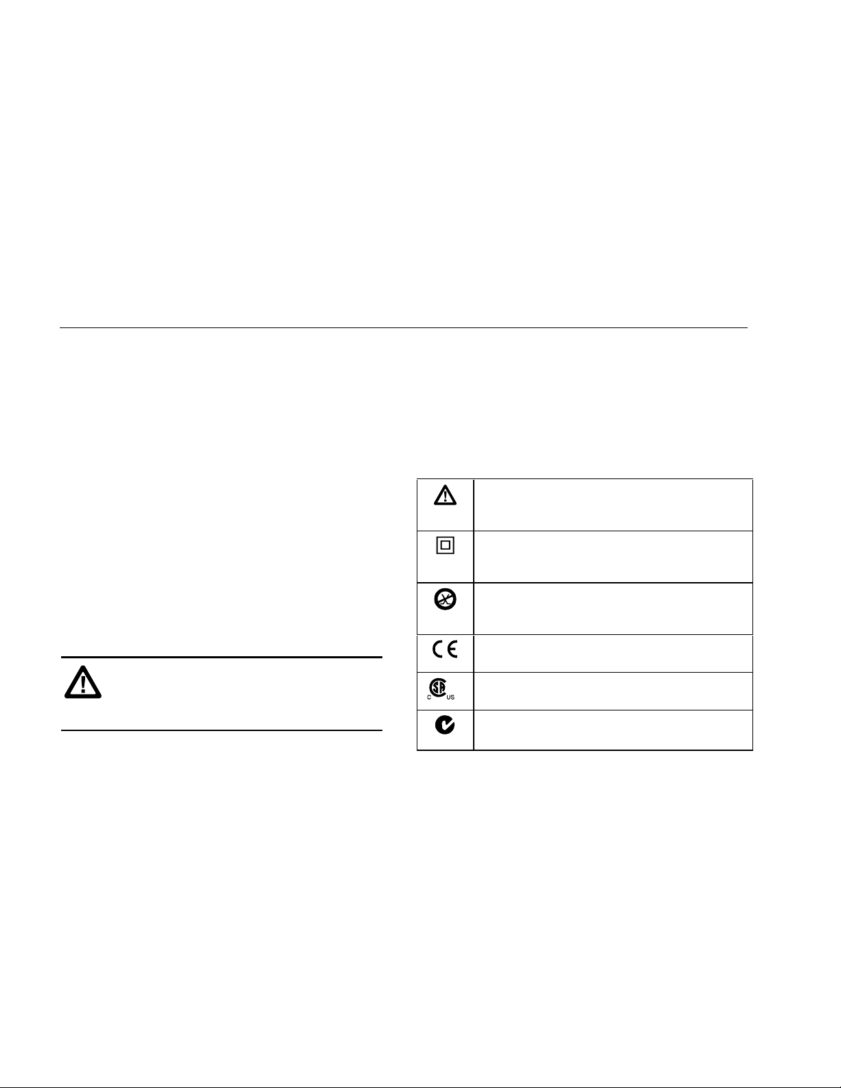
The international electrical symbols used on the
instrument or in this manual are described in Table 1.
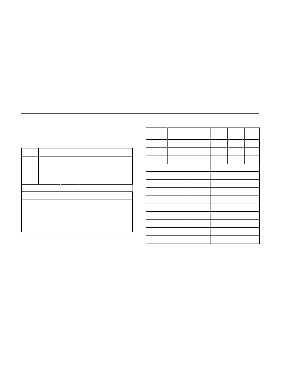
Table 1. International Electrical Symbols
ATTENTION: Risk of damage or destruction to
equipment or software. See explanations
marked with this symbol in the manual.
Equipment is protected by double insulation or
reinforced insulation to protect the user against
electric shock.
Do not connect this terminal to public
communications networks, such as telephone
systems.
Conforms to relevant European Union
Directives.
Conforms to relevant Canadian and US
Standards.
Conforms to relevant Australian standards.
N223
1788-UM002A-US-P – April 2000
Page 3
Safety Information
ATTENTION: To avoid possible fire, electric shock, personal injury, or damage to the MediaChecker:
• Do not connect the MediaChecker to any telephony inputs, systems, or equipment, including ISDN. Doing
so is a misapplication of this product, which can result in damage to the instrument and create a potential
shock hazard to the user.
• Do not connect the MediaChecker to active inputs, systems, or equipment. Doing so is a misapplication of
this product, which can result in damage to the instrument and create a potential shock hazard to the
user. Disable network power sources and all communication nodes before connecting the MediaChecker.
• Do not apply more than 25 V dc to any MediaChecker input. Use caution when connecting the
MediaChecker to a network, as voltages greater than 25 V dc may be present on nearby conductors.
• Always turn on the MediaChecker before connecting it to a cable. Turning the MediaChecker on activates
the tool’s input protection circuitry.
• Do not open the MediaChecker's case (except to replace the batteries). No user-serviceable parts are
inside.
• To avoid false test results, replace the batteries as soon as “LOW BATTERY” appears in the display.
• Use only batteries recommended by the manufacturer.
• Do not use the MediaChecker if it is damaged. Protection may be impaired. Inspect the MediaChecker for
physical damage before each use.
• Do not attempt to insert any connector other than an RJ45 connector into the RJ45 jack. Inserting other
connectors, such as RJ11 (telephone) connectors, can permanently damage the jack.
• Do not operate portable transmitting devices during a cable test. Doing so might cause erroneous test
results.
• To avoid false test results, do not run cable tests with cables attached to more than one connector on the
MediaChecker or with network equipment attached to the cable under test.
3
1788-UM002A-US-P – April 2000
Page 4
4
Getting Acquainted
Getting Acquainted
Display, Switches, and Connections
MediaChecker
1788-MCHKR
SETUP
5
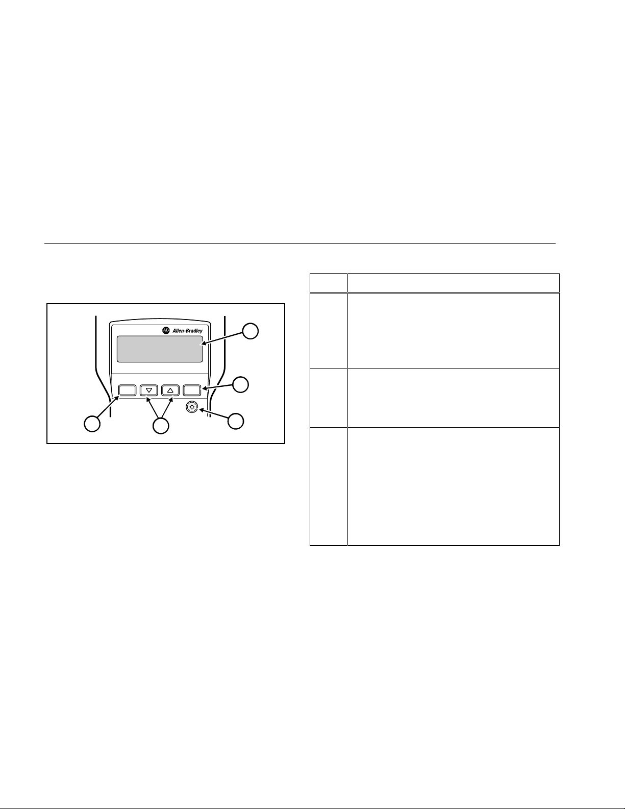
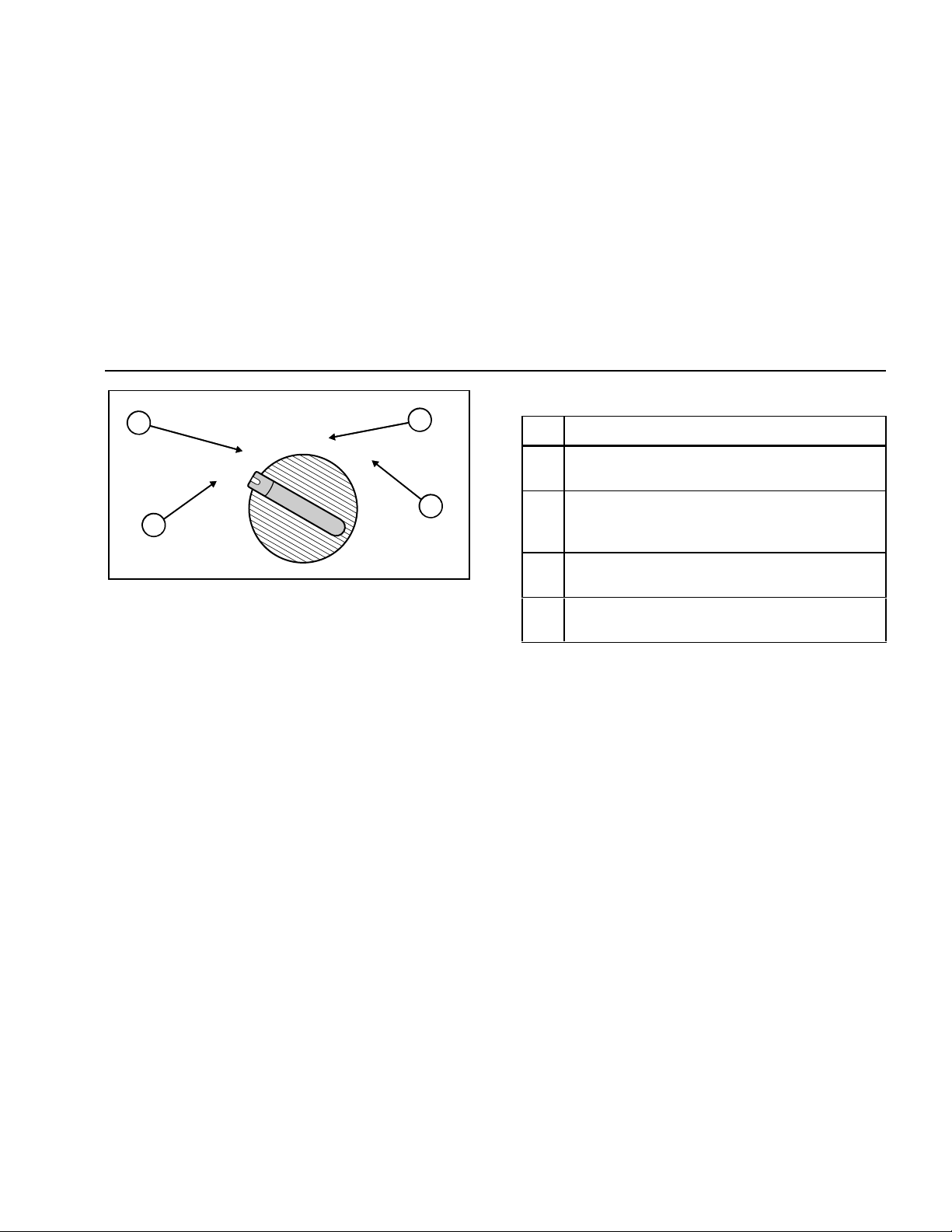
Figure 1. Front Panel Features
ENTER
4
Table 2. Features
Item Function
A
1
LCD
A 2-line by 16-character LCD display. When there is
more information than can be displayed on two lines,
an up arrow
[, down arrow ], or bidirectional arrow
^ appears in the left side of the display. Press the
corresponding
additional information.
2
B
3
C
aan01f.eps
D
E
E
Enters a selection into the MediaChecker and moves to
the next setup selection. Causes current cable
selection to be displayed and a new measurement
cycle initiated when not in Setup Mode.
B
Turns the display backlight on or off. Backlighting turns
off automatically after 60 seconds.
D C
Scrolls through a selection of choices or multiple
displays.
A
Provides access to cable selection, calibrat i on, and
other MediaChecker settings.
C or D key to display the
1788-UM002A-US-P – April 2000
Page 5
Getting Acquainted
5
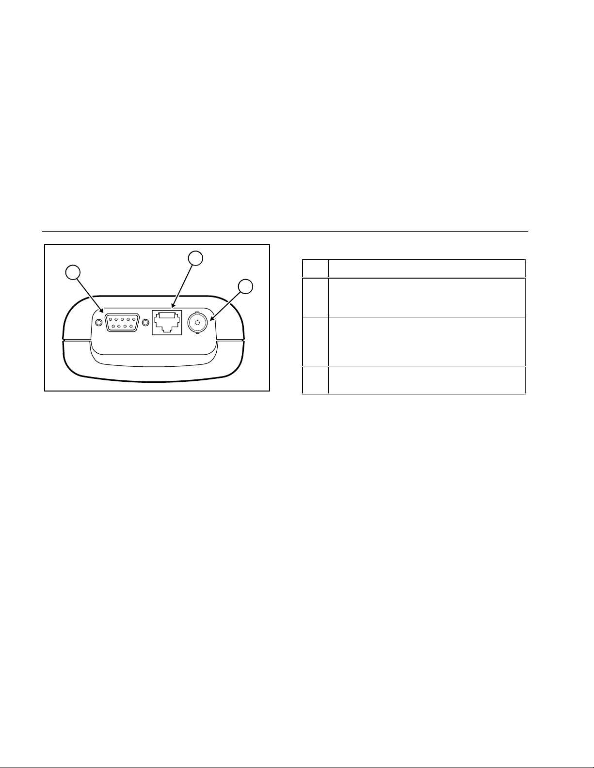
Table 3. Rotary Switch Positions
2
LENGTH
TEST
OFF
WIRE MAP
3
Item Description
A Turns the MediaChecker off. See “Battery Save
Mode” for more information.
4
1
B Tests the attached cable and provides a pass or
fail summary based on the parameters specified
for the selected cable.
C Displays the length of the attached cable in feet or
Figure 2. Rotary Switch
aan02f.eps
meters and tests for anomalies.
D Displays wiring connections, shorts, opens, and
split pairs.
1788-UM002A-US-P – April 2000
Page 6
6
Getting Acquainted
2
1
3
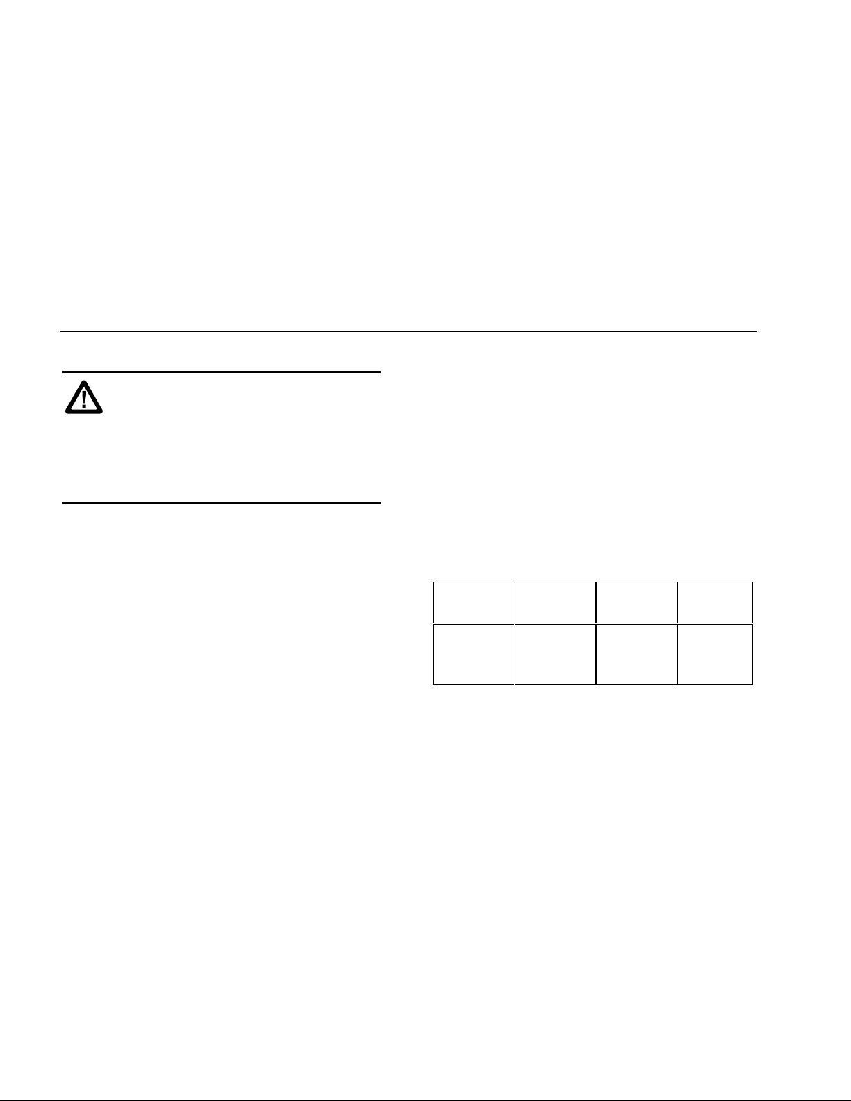
Item Description
A Standard 9-pin (DB9) connector for connecting
DeviceNet and DH+/RIO cables (using the
adapter provided).
B Standard 8-pin modular jack for connecting
Table 4. Connections
STP UTP/FTP COAX
unshielded (UTP) and foil-screened (FTP)
unshielded twisted pair cable for Ethernet IEEE
802.3 networks.
C BNC connector for connecting ControlNet
cables.
without the Cable ID detected.
the Cable ID detected.
pressed.
Figure 3. Connections
aan03f.eps
Audible Signal (Beeper)
The MediaChecker’s beeper indicates various conditions:
• A single, short tone indicates a pass condition
• A two-frequency tone indicates a pass condition with
• Three short tones indicate a test failure.
• A long tone sounds whenever an invalid key is
1788-UM002A-US-P – April 2000
Page 7

Getting Acquainted
7
• A continuous, varying-pitch tone indicates the
MediaChecker is connected to an active cable and
should be disconnected immediately. “ACTIVE
CABLE” is displayed.
To disable the audible signal for the “PASS” and “FAIL”
conditions, see “Setup Selections” on page 35. The tone
that indicates an active cable cannot be disabled.
Low Battery Indication
When the battery voltage is low but it is OK to continue,
the MediaChecker displays “LOW BATTERY” once during
power-up. When this message first appears there are
about 8 hours of use left. When the battery voltage is too
low to continue, the unit displays “REPLACE BATTERY”.
To continue using the MediaChecker, you must replace
the batteries. Refer to “Replacing Batteries” on page 36.
Battery Save Mode
The MediaChecker turns itself off when there is no switch
or key activity for 10 minutes. To return the
MediaChecker to operation, you must turn the rotary
switch to OFF and wait 5 seconds before turning the
MediaChecker back on.
To disable the Battery Save feature, turn the rotary switch
to OFF, then press and hold E while turning the rotary
switch to TEST. To re-enable the Battery Save feature,
turn the MediaChecker off, then on again.
Cable ID Unit
The Cable ID lets you detect wiring failures on twisted
pair cable. Test results can vary depending on whether
the ID unit is connected or not. See Table 7 on page 14
and “Twisted Pair Cable Test Results” on page 15 for
more information.
Selecting the Display Language
The MediaChecker displays messages in English,
French, German, Spanish, and Japanese. To change the
display language, do the following:
1. With the MediaChecker off, press and hold A
while turning the rotary switch to TEST.
2. Press C or D until the desired language is
displayed, then press A.
1788-UM002A-US-P – April 2000
Page 8
8
Preparing the MediaChecker for Use
Preparing the MediaChecker for Use
ATTENTION: To reduce wear on the
MediaChecker connector, leave the adapter
connected to the MediaChecker whenever
possible.
Plugging a 4 or 6 position plug into the
MediaChecker’s UTP/FTP jack can
permanently damage the jack pins.
Important: The noise filter should be set to the
frequency of the local power mains (50 Hz or
60 Hz). See “Setup Selections” on page 35
for this and other customizing selections.
After connecting the cable under test to the appropriate
connector on top of the MediaChecker, you must select
proper cable type, category, and size before testing or
measuring. It may also be necessary to calibrate the
MediaChecker to the cable under test. See “Calibrating
the MediaChecker to a Cable” on page 10.
Important: Never run cable tests with more than one
cable connected to the MediaChecker.
Doing so can cause erroneous results.
If you think the MediaChecker is not performing properly,
refer to “When Something Goes Wrong” on page 36.
Selecting a Cable Type
Characteristics for a variet y of Rockwell Automation’s
industrial commercial network cables are stored in the
MediaChecker and can be accessed through SETUP.
See Table 5.
Table 5. Predefined Cable List
ControlNet
(CNET)
RG6
RG6F
DS3/4
DeviceNet
(DNET) DH+/RIO
Thick
Thin
KwikLink
1770-CD
9022
9463
Ethernet
(ENET)
UTP
FTP
1788-UM002A-US-P – April 2000
Page 9

Preparing the MediaChecker for Use
9
To set up the MediaChecker for the desired cable, do the
following:
Important: The number of steps necessary to select a
cable definition depends on the type of
network selected.
1. Turn the MediaChecker on by turning the rotary
switch to TEST, LENGTH, or WIRE MAP.
2. Press A.
3. Press C or D until the desired network is
displayed, then press E.
4. Press C or D until the desired cable type is
displayed, then press E.
Steps 5 and 6 apply only to Ethernet:
5. Press C or D until the desired category is
displayed, then press E.
6. Press C or D until the desired wire size is
displayed, then press E.
7. Press A or turn the rotary switch to a new position
to exit the setup menu.
Important: You can check the cable selection at any
time other than when in the setup mode by
pressing the E key.
The MediaChecker will now test according to the cable
characteristics defined by the factory settings for the
cable selected. However, cables coming from different
batches or manufacturers can have characteristic
variances of up to 20 %, causing deviations in length
measurements. For more accurate measurements,
calibrate the MediaChecker to a known length of the
cable to be tested. See “Calibrating the MediaChecker to
a Cable” on page 10.
1788-UM002A-US-P – April 2000
Page 10

10
Preparing the MediaChecker for Use
Calibrating the MediaChecker to a Cable
Cables from different batches or manufacturers can have
characteristic variances of up to 20 %, causing deviations
in length measurements. To ensure maximum accuracy
of length measurements, calibrate the MediaChecker to a
known length of the cable to be tested.
Important: The MediaChecker is calibrated at the
factory to provide length measurements that
are accurate enough for most applications.
In most cases, you will not need to calibrate
the MediaChecker to a specific cable.
When you calibrate the MediaChecker to a specific cable,
use a known length of cable at least 100 ft (30 m) long
and of the same type and category as the cable under
test. Calibrating with cables longer than 100 ft (30 m) will
improve the accuracy of length measurements.
During the calibration process, if the cable is found to be
defective or if the cable is less than 50 ft (15 m) long,
“BAD CABLE” is displayed and the calibration process is
terminated.
Important: To ensure accurate measurements, be sure
that conductive objects, including fingers, do
not touch any of the cable connectors or
conductors during calibration or cable tests.
To calibrate the MediaChecker to the currently selected
cable, do the following:
1. Connect a good cable of known length, 100 ft
(30 m) or longer, to the appropriate MediaChecker
connector.
Important: If you have just finished selecting a cable
type, the MediaChecker should already
show the calibration selection display shown
below. In this case, read the Important note
after step 3; then continue the calibration
process with step 4. Otherwise, continue
with step 2.
1788-UM002A-US-P – April 2000
Page 11
Preparing the MediaChecker for Use
11
2. Turn the rotary switch to TEST, LENGTH, or WIRE
MAP.
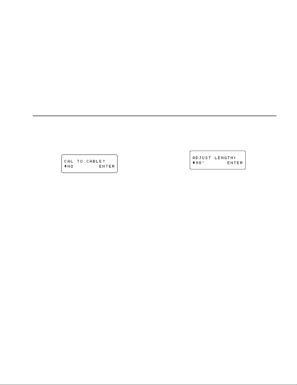
3. Press A; then press E repeatedly until the
following display appears:
aan06f.eps
Important: If the MediaChecker has already been
calibrated to the selected cable type, “CAL”
appears on the second line of the second
display shown at power-up. This display
appears for about 3 seconds before testing
begins. To erase this calibration and use the
factory settings, remove all cables from the
MediaChecker, press C D until “YES”
appears; then press E.
Press E anytime (except in setup mode)
to see the calibration status for the currently
selected cable.
4. Press C D until “YES” appears, and then press
E. The MediaChecker takes a few measurements
on the attached cable and displays the measured
length.
aan07f.eps
5. Press C D until the display shows the known
cable length, and then press E.
These cable parameters are stored and remain in
memory even if the MediaChecker is turned off. All future
measurements for this cable type are compared to the
new parameters until you perform a new calibration for
the cable type.
1788-UM002A-US-P – April 2000
Page 12
12
Key to Twisted Pair Displays
Key to Twisted Pair Displays
Table 6 describes the symbols used for DeviceNet,
DH+/RIO, and Ethernet displays.
Table 6. Key to Twisted Pair Displays
ID-- No Cable ID detected
IDRA Cable ID detected
ID??
IDRA
DeviceNet Wire Display Clip/Wire Color
“??” alternates with “RA”. Cable ID partially
detected. There is a problem with the cable or
ID unit.
V + + Red
CAN_H H White
Shield S Bare
CAN_L L Blue
V - - Black
Table 6. Key to Twisted Pair Displays (cont.)
DH+/RIO
Wire
Line 1 1 1 Blue Blue Clear
Shield 2 S Bare Bare Bare
Line 2 3 2 White Clear Blue
Ethernet 568A Display Wire Color
Ethernet 568B Display Wire Color
Phoenix
Pin Display
Pair 1: 4, 5 4 5 Blue, White/blue
Pair 2: 3, 6 3 6 White/orange, Orange
Pair 3: 1, 2 1 2 White/green, Green
Pair 4: 7, 8 7 8 White/brown, Brown
Pair 1: 4, 5 4 5 Blue, White/blue
Pair 2: 1, 2 1 2 White/orange, Orange
Pair 3: 3, 6 3 6 White/green, Green
Pair 4: 7, 8 7 8 White/brown, Brown
Clip
Color
RIO
Color
DH+
Color
1788-UM002A-US-P – April 2000
Page 13

The Test Function (TEST)
13
The Test Function (TEST)
The TEST function tests the attached cable and indicates
“PASS” or “FAIL” based on the cable’s compliance with
the parameters stored in the MediaChecker for the
selected cable. The tests that are performed (Table 7)
depend on whether or not a Cable ID is connected to the
far end of the cable.
To test only the wire map or measure only the cable
length, use the WIRE MAP or LENGTH functions. See
“Testing the Wire Map” on page 24 or “Measuring Cable
Length” on page 27.
To test a cable, do the following:
1. Disconnect all network devices (nodes) and remove
the terminator from the far end of the cable to be
tested. (For information on calculating the length of a
terminated cable, see “Calculating the Distance to a
Short” on page 32.)
2. For DeviceNet, DH+/RIO, and Ethernet cables,
connect the Cable ID to the far end of the cable, if
desired (refer to Table 7).
3. Connect the cable under test to the appropriate
connector on the MediaChecker. Use the included
adapter for DeviceNet or DH+/RIO cables.
4. Turn the rotary switch to TEST.
You can omit step 5 if you know the cable selection
is correct for the cable under test:
5. Press E to check the cable selection. The
MediaChecker displays the cable selection for a few
seconds, then starts the test. If the cable selection is
not correct, refer to “Preparing the MediaChecker for
Use” on page 8.
“CAL” appears in the second line of the display if a
cable calibration has been performed for the selected
cable type. See “Calibrating the MediaChecker to a
Cable” on page 10 for more information.
1788-UM002A-US-P – April 2000
Page 14
14
The Test Function (TEST)
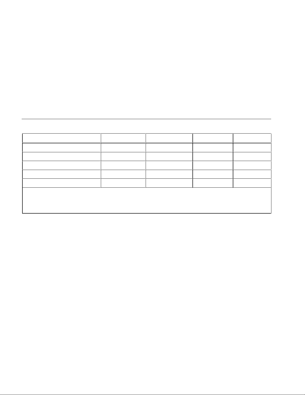
Table 7. Failures Detected for Each Cable Type
Failures Detected DeviceNet DH+/RIO Ethernet ControlNet
Distance to short Yes
Distance to open (near end) Yes
Length Yes
Split pair Yes
Wire map Yes
1. Measured for the data pair only. For shorted power wires, the MediaChecker displays the resistance of the short.
2. The distance to an open is the same as the measured length.
3. Split pair test not run on KwikLink cables.
4. Test available when using the Cable ID.
1
1
1
3
4
Yes Yes Yes
2
Yes
Yes Yes
Yes Yes Yes
No Yes No
Yes
4
Yes
4
2
No
1788-UM002A-US-P – April 2000
Page 15

The Test Function (TEST)
15
Twisted Pair Cable Test Results
Important: If you suspect inaccurate length readings,
calibrate the MediaChecker to the cable. See
“Calibrating the MediaChecker to a Cable” on
page 10.
Length measurements show the total length
of the trunk plus all drops on the cable. For
information on calculating the length of just
the trunk, drops, or taps, see “Calculating
Trunk, Drop, or Tap Lengths” on page 29.
Twisted pair cables include DeviceNet, DH+/RIO, and
Ethernet. When you test twisted pair cables, the
MediaChecker checks for the Cable ID at t he other end of
the cable and displays one of the following when a pass
condition exists:
“PASS” means the cable is
good. “RA” means the Cable
ID is detected.
aan09f.eps
“--“ means the Cable ID is not
detected. If the MediaChecker
does not detect a properly
aan59f.eps
connected Cable ID, the cable
is probably defective (most
likely at the far end).
Tables 8 and 9 show examples of DeviceNet cable
failures with and without the Cable ID connected.
DH+/RIO and Ethernet displays use the same fault
indicators, but show different symbols for the wires. (See
Table 6.)
Important: The MediaChecker may not detect the Cable
ID under some open and short conditions. The
MediaChecker alternately displays “??” and
“RA” (for “Resistive Adapter”) when the Cable
ID is detected but a problem with the cable or
the Cable ID is interfering with the identification
process.
1788-UM002A-US-P – April 2000
Page 16

16
The Test Function (TEST)
Table 8. DeviceNet Test Results (with Cable ID)
1
Display Failure Description
Short across the data pair
2
“SHORT” is blinking. L and H are shorted together at
approximately 600' (183 m).
Split pair
“SPLIT PR” is blinking. In this case, a power wire and a
data wire are swapped at the near end and swapped
back at the far end.
Open, or a wire is swapped with
the shield
“OPEN” is blinking. This can mean one of the following:
• The + wire is open somewhere along the cable.
• The + and S wires are swapped somewhere along
the cable.
1. The M edi aChecker might not be able to map some situations with four or five wires miswired. In all cases, the MediaChecker indicates
a fault and gives a partial description of the problem, but might not identify all of the wiri ng errors.
2. The distance to a short may not be reported, depending on the characteristics of the short. See “Calculati ng t h e Distance t o a Short” on
page 32 for more information.
1788-UM002A-US-P – April 2000
Page 17

The Test Function (TEST)
17
Table 8. DeviceNet Test Failures (with Cable ID) (cont.)
1
Display Failure Description
Short to the shield. “SHORT” is blinking. There is a resistive fault between S and L.
It could be a short or a slightly higher resistance. Check the
connectors first; then look for a crushed spot on the cable. You
can use an ohmmeter to measure the short’s resistance, then
use the information given under “Calculating the Distance to a
Short” on page 32 to determine the distance to the short.
2
Three wires are shorted.
“SHORT”, “FAULT”, and “OPEN” are blinking.
The L and –
wires are shorted to the shield (S). Use the measured resistance
(6 Ω in this case) and the information given under “Calculating
the Distance to a Short” on page 32 to determine the distance to
the short.
1. The M edi aChecker might not be able to map some situations with four or five wires miswired. In all cases, the MediaChecker indicates
a fault and gives a partial description of the problem, but might not identify all of the wiri ng errors.
2. B ecause some measurements are not possible on faulted cables, the MediaChecker might report the H wi re as open when it is no t
actually open.
1788-UM002A-US-P – April 2000
Page 18

18
The Test Function (TEST)
Table 9. DeviceNet Test Failures (without Cable ID)
Display Failure Description
The MediaChecker detects a
very high resistance between the
data lines and the “-” power line.
“FAULT” and “350Ω“ are blinking. There is probably
one or more I/O device connected to the cable under
test. To determine the cable length, do one of the
following:
• Disconnect the I/O devices and retest the cable.
• Install a terminator at the far end of the cable,
measure the resistance of the cable in series with
the terminator; then calculate the cable length. See
“Calculating the Distance to a Short” on page 32.
The MediaChecker detects a
fairly high resistance between
the CAN_H and CAN_L (data)
wires.
“FAULT” and “OPEN” are blinking.*
A terminator is probably connected to one end of the
bus. You can subtract the resistance of the terminator
(typically 120 Ω) from the measured resistance, then
calculate an approximate length using the remaining
resistance. See “Calculating the Distance to a Short”
on page 32.
To determine the cable’s wire map and get a more
accurate length measurement, replace the terminator
with the Cable ID and run the test again.
* Because some measurements are not possible on faulted cables, the MediaChecker might report t he + and – wires as open when they
are not actually open.
1788-UM002A-US-P – April 2000
Page 19

The Test Function (TEST)
Table 9. DeviceNet Test Failures (without Cable ID) (cont.)
19
Display Failure Description
The MediaChecker detects a low
resistance between the CAN_H
and CAN_L (data) wires;
however, the resistance is higher
than a short circuit.
The MediaChecker detects a low
resistance between the CAN_H
and CAN_L (data) wires.
2
“FAULT” and “OPEN” are blinking.
There is a resistive fault between L and H. The
resistance is higher than the resistance of a cable
1640 ft long (500 m), which is the maximum allowable
length.
“SHORT”, ≤954' (291 m), and “OPEN” are blinking.
There is a short between L and H. The MediaChecker
displays the most likely distance to the fault.
1
1
Connect the Cable ID to the far end of the cable and
repeat the test to check the + and – wires.
1. Because some measurements are not possible on faulted cables, the MediaChecker might report the + and – wires as open when
they are not actually open.
2. A short greater than zero ohms causes the MediaChecker to display a length greater than the actual distance to the short. See Figure 4
on page 23. The MediaChecker uses ohms/foot to calculate distance to a short.
1788-UM002A-US-P – April 2000
Page 20

20
The Test Function (TEST)
Table 9. DeviceNet Test Failures (without Cable ID) (cont.)
Display Failure Description
The MediaChecker measures a
very short length for the CAN_L
wire as compared to the other
wires.
“OPEN” is blinking.* The L wire is open at the near end.
To detect an open at the far end, connect the Cable ID
to the far end and repeat the test or connect the Cable
ID to this end of the cable and repeat the test from the
other end.
* Because some measurements are not possible on faulted cables, the MediaChecker might report t he + and – wires as open when they
are not actually open.
1788-UM002A-US-P – April 2000
Page 21

The Test Function (TEST)
21
Coaxial Cable Test Results
Important: If you suspect inaccurate length readings,
calibrate the MediaChecker to the cable. See
“Calibrating the MediaChecker to a Cable” on
page 10.
Length measurements show the total length
of the trunk plus all taps on the cable. For
information on calculating the length of just
the trunk, drops, or taps, see “Calculating
Trunk, Drop, or Tap Lengths” on page 29 or
refer to the Quick Reference Card.
When you test coaxial cables (ControlNet) with a
terminating resistor connected, the MediaChecker sounds
three short tones and displays the total resistance of the
terminator and cable wires:
aan10f.eps
Important: Coaxial cables must be unterminated for the
MediaChecker to display the cable’s length.
An open in a coaxial cable looks just like an
unterminated cable. If you know the cable
is longer than the measurement shows,
there is probably an open on the cable.
The MediaChecker sounds three short tones and displays
“FAIL” if a failure is detected.
Additional information about a failure is printed on the
second line of the display and if the ] symbol is
displayed, additional information can be viewed with the
D C keys.
Table 10 shows examples of ControlNet cable failures.
1788-UM002A-US-P – April 2000
Page 22

22
The Test Function (TEST)
Display Failure Description
Table 10. ControlNet Test Failures
The MediaChecker detects a cable length
greater than 2130 ft (650 m)
1
, which is the
maximum it can measure.
The MediaChecker detects a resistance that
is greater than the resistance of 2130 ft
(650 m)
1
of cable (about 65 Ω).
If “2130'“ (650 m)
1
is flashing, the cable is
longer than the maximum the
MediaChecker can measure. Break the
cable near its center and measure the two
parts separately.
A terminator resistor is probably connected
to one end of the bus. Remove the
terminator; then retest.
Or, subtract the terminator’s resistance
(75 Ω) from the measured resistance to get
the cable resistance. Then use the
procedure under “Calculating the Distance
to a Short” on page 32 to calculate the
cable length.
The MediaChecker detects a resistance that
is less than the resistance of 2130 ft (650 m)
of cable (about 65 Ω).
2
“SHORT” is blinking. A resistance less than
1
65 Ω (which is too low to be a terminator) is
across the line.
The display shows the most likely distance
to the fault.
1. The MediaChecker measures lengths to 650 m; however distances in feet beyond 999 ft are rounded to the nearest 10 ft.
2. A short greater than zero ohms causes the MediaChecker to display a length greater than the actual distance to the short. Figure 4
on page 23 illustrates this process using an Ethernet example. The MediaChecker uses ohms/foot to calculate distance to a short.
1788-UM002A-US-P – April 2000
Page 23

MediaChecker
SETUP
OFF
MediaChecker
SETUP
OFF
The Test Function (TEST)
23
80 Feet
1788-MCHKR
ENTER
LENGTH
WIRE MAP
TEST
0Ω SHORT
70 Feet
1788-MCHKR
ENTER
LENGTH
WIRE MAP
TEST
0.5Ω SHORT
Figure 4. Testing for Shorts (Ethernet Example)
aan04f.eps
1788-UM002A-US-P – April 2000
Page 24
24
Testing the Wire Map (WIRE MAP)
Testing the Wire Map (WIRE MAP)
Using the MediaChecker’s WIRE MAP function and the
Cable ID, you can determine the wiring of both the near
and far ends of twisted pair cables. To test the wire map,
do the following:
1. Connect the cable under test to the appropriate
connector on the MediaChecker.
2. Connect the Cable ID to the far end of the cable. Use
an adapter, if necessary.
3. Turn the rotary switch to WIRE MAP.
You can omit step 4 if you know the cable selection
is correct for the cable under test.
4. Press E to check the cable selection. The
MediaChecker displays the cable selection for a few
seconds and then starts the test. If the cable
selection is not correct, refer to “Preparing the
MediaChecker for Use” on page 8 for instructions on
selecting a new cable setting. “CAL” appears in the
second line of the display if a cable calibration has
been performed for the selected cable type.
Important: If you select the “COAX” cable type while in
the WIRE MAP mode, the MediaChecker will
perform the LENGTH test on the cable.
Assuming the cable attached to the MediaChecker is a
DeviceNet Thick cable with no failures, the following
display indicates a good cable:
Near End
Far End
aan13f.eps
The top line always displays the near end of the cable;
the second line always displays the far end.
1788-UM002A-US-P – April 2000
Page 25

Testing the Wire Map (WIRE MAP)
25
When the MediaChecker detects something on the far
end of the cable, but cannot determine if it is the Cable
ID, “ID” is displayed. The MediaChecker alternately
displays “??” and “RA” when the Cable ID is detected but
a problem with the cable or with the Cable ID is interfering
with the identification process.
Without the Cable ID connected to the far end of the
cable, the MediaChecker displays “--”.
The following display indicates the near end wiring of a
cable without the Cable ID connected:
aan14f.eps
Table 11 shows example of wire map failures on
DeviceNet cable.
1788-UM002A-US-P – April 2000
Page 26

26
Testing the Wire Map (WIRE MAP)
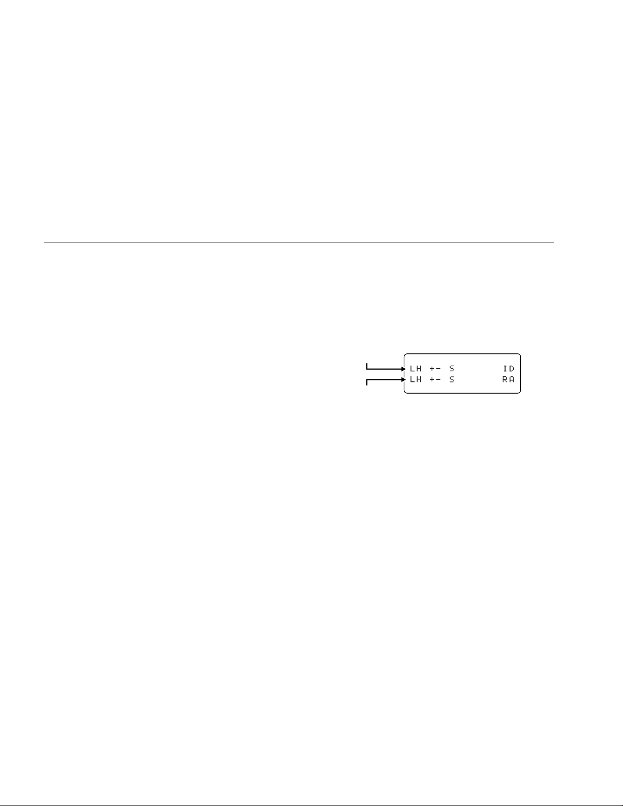
Table 11. DeviceNet Wire Map Failures (with Cable ID)
Display Failure
Miswire (wires
are swapped)
“H” and “+” are blinking. The first line on the display (LH +- S) shows the
near end connections. The second line (L+ H- S) shows far end
Description
connections. This mapping shows that the H and + wires are swapped.
Short The S and L wires are shorted together.
Open, or a wire
is swapped with
“o” is blinking in the bottom line. The “+” wire is open at the far end or is
swapped with the shield (S).
the shield
Multiple shorts*
“ss”, “L-”, and “o” are blinking. “ss” blinking indicates a short from L to S.
“L-” blinking indicates a fault between the L and – wires. Use TEST or
LENGTH to check the resistance between the wires.
Split pair
If nothing is blinking, the connection is good. If part of the display is
blinking (for example, “+-” in both rows), there is a split pair, or a fault that
the MediaChecker cannot clearly identify because the fault interferes with
testing.
* The MediaChecker alternately displays “??” and “RA” when the Cable ID is detected, but a problem with the cable or with the Cable ID is
interfering with the identificati on process.
1788-UM002A-US-P – April 2000
Page 27

Measuring Cable Length (LENGTH)
27
Measuring Cable Length (LENGTH)
Important: If you suspect inaccurate length readings,
calibrate the MediaChecker to the cable. See
“Calibrating the MediaChecker to a Cable” on
page 10.
Length measurements show the total length
of the trunk plus all drops or taps on the
cable. For information on calculating the
length of just the trunk, drops, or taps, see
“Calculating Trunk, Drop, or Tap Lengths” on
page 29.
Using the MediaChecker's LENGTH function, you can
measure the length of both twisted-pair and coaxial
cables. If the MediaChecker is not calibrated to the cable
under test, the factory defaults are used to compute the
length. If you require more accurate length
measurements, refer to “Calibrating the MediaChecker to
a Cable” described on page 10.
Before a length measurement is made, the MediaChecker
performs diagnostic tests to prevent any cable failures
from corrupting the length measurement. All failures are
described in the earlier sections “The TEST Function” and
“Testing the Wire Map”.
To measure the length of a cable, do the following:
1. Disconnect all network equipment and remove the
terminator from the far end of the cable to be tested.
(For information on calculating the length of a
terminated cable, see “Calculating the Distance to a
Short” on page 32.)
2. Connect the cable under test to the appropriate
connector on the MediaChecker.
3. Turn the rotary switch to LENGTH.
You can omit step 4 if you know that the cable
selection is correct for the cable under test.
1788-UM002A-US-P – April 2000
Page 28

28
Measuring Cable Length (LENGTH)
4. Press E to check the cable selection.
The MediaChecker displays the cable selection for a
few seconds and then starts the test. If the cable
selection is not correct, refer to “Preparing the
MediaChecker for Use” on page 8 to select a new
cable setting. “CAL” appears in the second line of the
display if a cable calibration has been performed for
the selected cable type.
Important: When a length measurement flashes on the
display, the length of the cable exceeds
either the maximum allowed by the standard
(for DeviceNet, DH+/RIO, and Ethernet
cables) or the MediaChecker’s range of
measurement (for ControlNet cables).
The information displayed depends on the type of cable
selected.
For a DeviceNet cable with no failures, the display shows
the following:
aan11f.eps
The MediaChecker cannot determine the length of a
coaxial cable terminated with a resistance. Only the total
resistance of the wire and the terminator is displayed. An
unterminated coaxial cable 445 ft long gives the following
result:
aan12f.e
1788-UM002A-US-P – April 2000
Page 29

Calculating Trunk, Drop, or Tap Lengths
29
Calculating Trunk, Drop, or Tap Lengths
When you test a cable that has drops or taps, the
MediaChecker reports the length of the trunk, plus the
total length of all the drops or taps on the trunk.
DeviceNet and DH+/RIO Length Calculations
Formulas:
Measure drop lengths with the MediaChecker or a tape measure.
• Trunk length = Measured length – Total actual length of drops
• Total drop length = Measured length – Trunk length
Example 1: Calculating trunk length
A cable measures 270 ft long. The cable has 2 drops of 15 ft each.
Trunk length = 270 ft measured length – 30 ft drop length = 240 ft trunk length
Example 2: Calculating total drop length
A cable measures 788 ft long. The trunk is 400 ft long.
Total length of drops = 788 ft measured length – 400 ft trunk length = 388 ft total drop length
This section shows how to calculate the length of just the
trunk or the total length of just the drops or taps.
1788-UM002A-US-P – April 2000
Page 30

30
Calculating Trunk, Drop, or Tap Lengths
ControlNet Length Calculations
Measured tap lengths depend on whether the taps are terminated or not. See Table 12.
Formulas:
• Trunk length = Measured length – Total measured length of taps
• Total tap length = Measured length – Trunk length
Example 1: Calculating trunk length
A cable measures 750 ft long and has 16 unterminated taps.
From Table 12, 16 unterminated taps = 69 measured ft
Trunk length = 750 ft measured length – 69 ft tap length = 681 ft trunk length
Example 2: Calculating total tap length and the number of taps
A cable measures 328 m long. The actual cable length is 274 m. The taps on the cable are terminated.
Measured (terminated) total tap length = 328 m – 274 m = 54 m
From Table 12, 54 meters of terminated taps corresponds to 23 taps.
1788-UM002A-US-P – April 2000
Page 31

Calculating Trunk, Drop, or Tap Lengths
31
Table 12. Measured Tap Lengths for ControlNet
Cables
Number
of Taps Terminated Tap* Unterminated Tap
1 8 ft (2.5 m) 4 ft (1.5 m)
2 16 ft (5 m) 9 ft (2.5 m)
3 23 ft (7 m) 13 ft (4 m)
4 31 ft (9.5 m) 17 ft (5 m)
5 39 ft (12 m) 22 ft (6.5 m)
6 47 ft (14.5 m) 26 ft (8 m)
7 55 ft (16.5 m) 30 ft (9 m)
8 62 ft (19 m) 34 ft (10.5 m)
9 70 ft (21.5 m) 39 ft (12 m)
10 78 ft (24 m) 43 ft (13 m)
11 86 ft (26 m) 47 ft (14.5 m)
12 94 ft (28.5 m) 52 ft (15.5 m)
13 101 ft (31 m) 56 ft (17 m)
14 109 ft (33.5 m) 60 ft (18.5 m)
15 117 ft (35.5 m) 65 ft (19.5 m)
16 125 ft (38 m) 69 ft (21 m)
17 133 ft (40.5 m) 73 ft (22.5 m)
Number
of Taps
Terminated Tap*
Unterminated Tap
18 140 ft (43 m) 77 ft (23.5 m)
19 148 ft (45 m) 82 ft (25 m)
20 156 ft (47.5 m) 86 ft (26 m)
21 164 ft (50 m) 90 ft (27.5 m)
22 172 ft (52.5 m) 95 ft (29 m)
23 179 ft (54.5 m) 99 ft (30 m)
24 187 ft (57 m) 103 ft (31.5 m)
25 195 ft (59.5 m) 108 ft (33 m)
26 203 ft (62 m) 112 ft (34 m)
27 211 ft (64 m) 116 ft (35.5 m)
28 218 ft (66.5 m) 120 ft (36.5 m)
29 226 ft (69 m) 125 ft (38 m)
30 234 ft (71.5 m) 129 ft (39.5 m)
31 242 ft (73.5 m) 133 ft (40.5 m)
32 250 ft (76 m) 138 ft (42 m)
33 257 ft (78.5 m) 142 ft (43 m)
34 265 ft (81 m) 146 ft (44.5 m)
35 273 ft (83 m) 151 ft (46 m)
* Terminated with 1786/1797-TCAP
1788-UM002A-US-P – April 2000
Page 32

32
Calculating the Distance to a Short
Table 12. Measured Tap Lengths for ControlNet
Cables (cont.)
Number
of Taps
36 281 ft (85.5 m) 155 ft (47 m)
37 289 ft (88 m) 159 ft (48.5 m)
38 296 ft (90.5 m) 163 ft (50 m)
39 304 ft (92.5 m) 168 ft (51 m)
40 312 ft (95 m) 172 ft (52.5 m)
41 320 ft (97.5 m) 176 ft (53.5 m)
42 328 ft (100 m) 181 ft (55 m)
43 335 ft (102 m) 185 ft (56.5 m)
44 343 ft (104.5 m) 189 ft (57.5 m)
45 351 ft (107 m) 194 ft (59 m)
46 359 ft (109.5 m) 198 ft (60.5 m)
47 367 ft (111.5 m) 202 ft (61.5 m)
48 374 ft (114 m) 206 ft (63 m)
* Terminated with 1786/1797-TCAP
Terminated Tap*
Unterminated Tap
Calculating the Distance to a Short
Depending on the type of short on a cable, the
MediaChecker may or may not be able to determine the
distance to the short. If the MediaChecker cannot report
the distance, you can use the information in this section
to calculate the distance to the short.
You can also use this information to calculate the
approximate length of a terminated cable.
The MediaChecker reports information on shorts and
terminated cables as follows:
Short across a data pair: The MediaChecker measures
the resistance of the short, then displays the distance to
the short based on the resistance.
Short across a power pair or from a power wire to a
data wire: The MediaChecker measures and displays the
resistance of the short. You can use the resistance value
to calculate the distance to the short.
1788-UM002A-US-P – April 2000
Page 33

Calculating the Distance to a Short
33
Short across the shield and any other wire: The
MediaChecker reports the short, but cannot measure its
resistance or determine the distance to the short. You can
use an ohmmeter to measure the resistance; then use the
resistance to calculate the distance to the short.
Terminated cable: The MediaChecker indicates a fault
and displays a resistance. To determine the approximate
length of a terminated cable, subtract the terminator’s
resistance (75 Ω for ControlNet; 120 Ω for DeviceNet)
from the measured resistance; then use the remaining
resistance as Rs in the following procedure. Note that the
terminator’s tolerance will add some degree of error to the
calculation.
Important: When testing Ethernet cable, the
MediaChecker can report the distance to all
the shorts described above because
additional test data is available from other
wire pairs.
Use the following formula to calculate the distance to a
short. Refer to Tables 13 and 14 for cable resistances.
Distance to short =
Rs: Resistance of the short, as measured by the
MediaChecker or with your own meter.
R1: Resistance per unit of length of one of the shorted
conductors.
R2: Resistance per unit of length of the other shorted
conductor.
Following is a sample calculation:
A DeviceNet Thin cable is shorted across H and the
shield. Here are the resistance values:
• Rs (as measured with an ohmmeter): 10 Ω
• R1 (resistance of H): 0.028 Ω/ft
• R2 (shield resistance): 0.0032 Ω/ft
Distance to short =
=
0.0312 Ω/ft
0.028 Ω/ft + 0.0032 Ω/ft
10 Ω
Rs
R1 + R2
10 Ω
= 321 ft
1788-UM002A-US-P – April 2000
Page 34

34
Calculating the Distance to a Short
Table 13. DeviceNet and DH+/RIO Cable Resistances
Data Pair
Cable Type
DeviceNet
Thick
DeviceNet
Thin
DeviceNet
KwikLink
DH+/RIO 0.00944 Ω/ft
(H, L)
0.0069 Ω/ft
0.0226 Ω/m
0.028 Ω/ft
0.0918 Ω/m
0.00404 Ω/ft
0.01325 Ω/m
0.031 Ω/m
Power Pair
(+,-) Shield
0.0032 Ω/ft
0.0105 Ω/m
0.01617 Ω/ft
0.053 Ω/m
0.00404 Ω/ft
0.01325 Ω/m
NA 0.0041Ω/ft
0.00175 Ω/ft
0.00575 Ω/m
0.0032 Ω/ft
0.0105 Ω/m
NA
0.0135 Ω/m
Table 14. ControlNet Cable Resistances
Cable Type Center
Conductor
ControlNet RG6
ControlNet RG6F
ControlNet DS3/4
0.028 Ω/ft
0.0918 Ω/m
0.0099 Ω/ft
0.0325 Ω/m
0.0255 Ω/ft
0.0836 Ω/m
Shield
0.0036 Ω/ft
0.0118 Ω/m
0.0029 Ω/ft
0.0095 Ω/m
0.0032 Ω/ft
0.0105 Ω/m
1788-UM002A-US-P – April 2000
Page 35

Setup Selections
35
Setup Selections
In setup mode you can select cable characteristics and
customize the MediaChecker’s operation. Once changed,
these settings are stored and remain in the
MediaChecker even when it is turned off.
In setup mode you can do the following:
• Select a network protocol (Ethernet, ControlNet,
DeviceNet, DH+/RIO)
• Select a cable type
• Select a cable category
• Select a wire size
• Calibrate the MediaChecker to a specific cable
• Enable or display the beeper for “PASS” and “FAIL”
results
• Adjust the display contrast
To make a SETUP selection, do the following:
1. Press A.
2. Press E to step through the selections.
3. Press C or D to select the desired setup
condition.
4. Press A to exit the setup mode, or press E to
move to the next setup selection.
Setup selections that rarely need changing are under a
special “Power-up” menu. From the Power-up menu, you
can do the following:
• Select the display language
• Select length measurement units between feet (‘)
and meters (m)
• Select wire size units between AWG and millimeters
(mm)
• Set the noise filter for 50 Hz or 60 Hz
To make a Power-up setup selection, do the following:
1. With the MediaChecker OFF, press and hold A
while turning the rotary switch to TEST.
2. Press E to step through the selections.
3. Press C or D to select the desired setup
condition.
4. Press A to exit the setup mode, or press E to
move to the next setup selection.
1788-UM002A-US-P – April 2000
Page 36

36
Maintenance
Maintenance
General
Periodically wipe the case with a damp cloth and
detergent; do not use abrasives or solvents. Clean and
dry as required. If the MediaChecker will remain unused
for an extended period, remove the batteries to prevent
damage from leakage.
Replacing Batteries
Two 1.5 V AA alkaline batteries power the MediaChecker
and typically provide 50 hours of operation. Using the
backlight may significantly reduce battery life. Figure 5
shows how to replace the batteries.
Determining the Software Version
The version number of your MediaChecker’s software
appears briefly on the display when you turn on the
MediaChecker. To hold the version number on the
display, hold down A while turning on the
MediaChecker.
1788-UM002A-US-P – April 2000
+
+
aan05f.eps
Figure 5. Replacing the Batteries
When Something Goes Wrong
If the MediaChecker seems to be malfunctioning, try the
troubleshooting steps in Table 15 before returning the
MediaChecker to Rockwell Automation for repair.
Page 37

Table 15. Troubleshooting the MediaChecker
Symptom 1: Display goes blank.
Action Result Explanation
1. Turn the rotary switch to OFF, wait 5 seconds and turn
the switch to TEST.
page 36).
Display is active
Display still blank Go to step 2.
Display is active Bat teries were too low to run the MediaChecker.2. Replace the batteries (see “Replacing Batteries” on
Display still blank Go to step 3.
The Battery Save feature turned the MediaChecker
off.*
Maintenance
37
3. Return the MediaChecker for repair. See “Returning the
MediaChecker for Repair” on page 39.
Symptom 2: The MediaChecker seems to be measuring incorrectly.
Self-test fails Internal circuitry is defective. Go to step 3.1. Perform a self-test on the MediaChecker. See
“Performing a Self-Test” on page 38.
2. Calibrate the MediaChecker as described on page 10. Calibration not effective Go to step 3.
3. Return the MediaChecker for repair. See “Returning the
MediaChecker for repair” on page 39.
* To disable Battery Save, turn the rotary switch to OFF, then press and hold E while turning the rotary switch to TEST.
Self-test passes Go to step 2.
Problem appears to be a MediaChecker
malfunction.
Problem appears to be a MediaChecker
malfunction.
1788-UM002A-US-P – April 2000
Page 38

38
Maintenance
Performing a Self-Test
When the MediaChecker is on, it periodically tests some
of its internal circuits. If a problem is detected, the
MediaChecker displays the following message:
aan16f.eps
You can perform a more thorough self-test on DeviceNet,
DH+/RIO, and Ethernet functions as follows:
1. With the MediaChecker off, press and hold A
while turning the rotary switch to TEST.
2. Press E until “SELF-TEST?” is displayed.
3. Press C or D to select “YES”.
Important: To exit without performing a self-test, either
press A, or ensure that the second line is
displaying “NO” and press E to move to
the next setup selection.
4. Press E to activate the self-test program.
You will be prompted to install the Cable ID. There
are two ways to install the Cable ID, each with
different results:
• To run a self-test on DeviceNet and DH+/RIO
functions, connect a DB9-to-Mini/Micro male
adapter in series with a Mini/Micro female-to-DB 9
adapter. Use this series combination to connect
between the DB9 connector on the Cable ID and
the DB9 connector on the MediaChecker.
1788-UM002A-US-P – April 2000
Page 39

Maintenance
39
• To run a self-test on Ethernet functions, connect
an Ethernet patch cord to the RJ45-to-DB9
adapter. Use this series combination to connect
from the DB9 connector on the Cable ID to the
RJ45 connector on the MediaChecker.
5. After installing the Cable ID, press E to continue
the self-test program.
The MediaChecker displays “PASS” or “FAIL”. The selftest repeats until you press A or the MediaChecker
turns itself off (Battery Save function).
If any failure is detected, return the unit to Rockwell
Automation for repair.
To check the MediaChecker's coaxial cable functions, run
the TEST and LENGTH tests on a known length of cable.
Returning the MediaChecker for Repair
If after performing the previous tests you believe the
MediaChecker is not performing properly, send the
complete kit to a local Rockwell Automation location for
repair. Rockwell Automation assumes no responsibility for
damage in transit.
A 1788-MCHKR MediaChecker covered by the limited
warranty will be promptly repaired or replaced (at
Rockwell Automation’s option) and returned to you at no
charge. If the warranty has lapsed, the MediaChecker will
be repaired and returned for a fixed fee. Contact a
Rockwell Automation distributor for information and
prices.
1788-UM002A-US-P – April 2000
Page 40

40
Maintenance
Parts and Accessories
Table 16. Parts and Accessories
Description Part No.
RA (Resistive Adapter) cable identifier with female DB9 connector 97157801
Users manual (multi-language) 957259-13
Quick reference card 957259-93
1788-MCHKR Accessory Kit
• 1 RJ-45F to DB9 male adapter
• 1 RJ-45 to RJ-45 straight-through patch cable
• 2 Male DB9 to male 3-pin Phoenix adapters
• 2 Male DB9 to male 5-pin Phoenix adapters
• 2 Male DB9 to male mini adapters
• 2 Male DB9 to male micro adapters
• 2 Male DB9 to 5 alligator clips lead
• 1 Male DB9 to female micro adapter
• 1 Male DB9 to female mini adapter
1788-MCHKRACC
1788-UM002A-US-P – April 2000
Page 41

Specifications
41
Specifications
These specifications assume the MediaChecker was
calibrated using 100 ft (30 m) (or more) of cable of the
same type and batch as the cable being measured.
Accuracy is specified for two years after calibration.
Coax Termination Measurements
Any loop resistance value between 5 Ω and 350 Ω is
interpreted as a terminator resistance. Resistance values
below 5 Ω are considered shorts; resistance values
greater than 350 Ω are displayed as >350 Ω.
Input Connectors
RJ45, DB-9, and BNC
Input Protection
Will withstand connection to any of the supported
networks in a live condition with a supply voltage not
exceeding 25 V.
“ACTIVE CABLE” is displayed and an audible signal
sounds when the MediaChecker is connected to a cable
with voltage present.
ATTENTION: Never connect the
MediaChecker to any telephony inputs,
systems, or equipment, including ISDN.
Table 17. Cable Test Characteristics
Network Cable Wiring Pass/Fail Pins
DeviceNet Thick and
Thin
DeviceNet KwikLink DeviceNet Data pair,
DH+/RIO Blue Hose
or similar
ControlNet RG6,
RG6F,
DS3/4
Ethernet UTP/FTP EIA/TIA
DeviceNet Data pair, power
pair, shield
power pair
DH+ Data pair, shield
Coaxial Center pin and
shield
Wire pairs 1, 2;
4-pair
3, 6; 4, 5; 7, 8
Also the foil
(shield) for FTP
1788-UM002A-US-P – April 2000
Page 42

42
Specifications
Cable
Table 18. ControlNet Cable Test Specifications
Cable Length Distance to Short
1
Range
Accuracy Resolution
2
Accuracy Resolution
2
ControlNet RG-6
ControlNet RG-6F (high flex RG-6)
ControlNet DS3/4 5065
1. For these cable types, the length to an open is displayed, but the “OPEN” error message is not displayed.
2. 0.5 m (1 ft) for cables <100 m long (328 ft); 1 m (5 ft) for cables >100 m long; 1 ft (0.5 m) for cables to 999 ft long (305 m); 10 ft for
cables > 999 ft long.
1 m to 650 m
(2 ft to 2130 ft)
10 % + 1 m (6 ft)
0.5 m (1 ft)
10 % + 10 m
(10 % + 30 ft)
1 m (5 ft)
Table 19. DeviceNet Cable Test Specifications
Cable Length Distance to Short
Cable
1
Range
2
Accuracy Resolution Accuracy
2
Resolution
DeviceNet Thick 1 m to 500 m (3 ft to 1640 ft)
DeviceNet KwikLink 1 m to 420 m (3 ft to 1380 ft)
7 % + 2 m (6 ft) See Note 3
DeviceNet Thin 1 m to 100 m (3 ft to 328 ft)
1. For these cable types, the length to an open is displayed, but the “OPEN” error message is not displayed.
2. For the data pair only. Lengths greater than 999 ft are rounded to the nearest 10 ft.
3. 0.5 m (1 ft) for cables <100 m long (328 ft); 1 m (5 ft) for cables >100 m long; 1 ft (0.5 m) for cables to 999 ft long (305 m); 10 ft (3 m)
for cables >999 ft long.
1788-UM002A-US-P – April 2000
10 % + 12 m (40 ft) 1 m (5 ft)
7 % + 3 m (10 ft) 0.5 m (1 ft)
3
Page 43

Cable
Specifications
43
Table 20. DH+/RIO Cable Test Specifications
Cable Length Distance to Short
1
Range
Accuracy Resolution
2
Accuracy
3
Resolution
2
DH+/RIO 1770-CD
DH+/RIO 9022
1 m to 350 m
(2 ft to 999 ft)
7 % + 2 m (6 ft) See Note 2
7 % + 3 m
(7 % + 10 ft)
0.5 m (1 ft)
DH+/RIO 9463
1. For these cable types, the length to an open is displayed, but the “OPEN” error message is not displayed.
2. 0.5 m (1 ft) for cables <100 m long (328 ft); 1 m (5 ft) for cables >100 m long; 1 ft (0.5 m) for cables to 999 ft long (305 m); 10 ft (3 m)
for cables >999 ft long.
3. For the data pair only.
Table 21. Ethernet Cable Test Specifications
Test Range Accuracy Resolution
2
Cable length 7 % + 0.5 m (1 ft)
Distance to short 7 % + 3 m (7 % + 10 ft)
1 m to 350 m (2 ft to 999 ft)
0.5 m (1 ft)
Distance to open 7 % + 3 m (7 % + 10 ft)
Split pairs
1. Testing for split pairs requires 2 or more pairs with similar capacitance. Split pai r sect i on of the cable must be at least 2 meters (6 ft)
2. 0.5 m (1 ft) for cables <100 m long (328 ft); 1 m (5 ft) for cables >100 m long; 1 ft (0.5 m) for cables to 999 ft long (305 m); 10 ft (3 m) for
1
long and greater than 10 % of the total cable length.
cables >999 ft long.
NA NA
1788-UM002A-US-P – April 2000
Page 44

44
Specifications
Power
Two AA size 1.5 V alkaline batteries
Battery type: ANSI/NEDA-15A or IEC-LR6
Low battery indicated on the display
Typical battery life: 50 hours
Timed power-off function (Battery Save feature)
Dimensions
18.4 cm x 9.8 cm x 4.6 cm
(7.25 in x 3.875 in x 1.8 in)
Weight
354.4 g (12.5 oz)
Environmental Conditions
Temperature
Non-operating (storage): -20 °C to +60 °C
Operating: 0 °C to +45 °C
Operating Humidity
10 °C to 30 °C: 95 % ±5 % RH (without condensation)
30 °C to 40 °C: 75 % ±5 % RH (without condensation)
40 °C to 45 °C: 45 % ±5 % RH (without condensation)
Altitude
Non-operating: 0 km to 12 km (40,000 ft)
Operating: 0 km to 4.57 km (15,000 ft)
Electromagnetic Compatibility
Meets FCC part 15-b
Meets EN 50081-1: 1993, EN 50082-1; 1995
Meets AS/NZS 2064
N223
Safety
EN60950 2nd edition, 1,2,3,4 Low Voltage
Directive
C22.2 No. 950 2nd edition (1996)
Display
LCD (2 lines of 16 characters) with backlight
Controls
Four-position rotary switch and 5 tactile-feedback
momentary switches
Warranty
One year from date of purchase
Calibration Period
Two years from manufacturing date
1788-UM002A-US-P – April 2000
 Loading...