

Page 1

Installation Instructions
DeviceNet Power Supply
Catalog Number 1787-DNPS
Use this document as a guide when you install a DeviceNet™ Power
Supply (model number CP680).
About the Power Supply
European Union Directive Compliance
:HGHVLJQHGWKH'HYLFH1HWSRZHUVXSSO\VSHFLILFDO O\IRU'HYLFH1HW
QHWZRUNV,WFRQIRUPVWRDOODSSOLFDEOHQDWLR QDOHOHFWULFFRGHV
The power supply provides the following features:
• standard IEC 3-pin connector
• main power switch with a dual-voltage selection switch
• standard DeviceNet 5-pin open style connector
• stud for earth to ground connection
• green LED power indicator
• stud for earth-to-ground connection
If this product bears the marking, it is approved for installation within
the European Union and EEA regions. It has been designed and tested to
meet the following directiv es.
EMC Directive
This product is tested to meet Council Directive 89/336/EEC
Electromagnet ic Compatibility (EMC) and the following standards, in
whole or in part, documented in a technical construction file:
• EN 50081-2EMC - Generic Emission Standard, Part 2 - Industrial
Environment
ΕN 50082-2EMC - Generic Immunity Standard, Part 2 - Industrial
•
Environment
This product is intended for use in an industrial environment.
Low Voltage Directive
This product is tested to meet Council Directive 73/23/EEC Low Voltage,
by applying the safety requirements of EN 61131-2 Programmable
Controllers, Part 2 - Equipment Requirements and Tests.
1787-5.8 - February 1999
Page 2
2 DeviceNet Power Supply
For specific information on the power supply requirements, see the
appropriate sections in this manual as well as the following
Allen-Bradley publications:
• Industrial Automation Wiring and Ground Guidelines, publication
1770-4.1
• Automation Systems Catalog, publication B111
This equipment is classified as open equipment and must be installed
(mounted) in an enclosure during operation as a means of providing safety
protection.
Installing Your Power Supply
You can install your power supply on a vertical wall mount or a shelf by
using the integral mounting brackets. For more information about where to
mount your power supply, refer to the DeviceNet Cable System Planning
and Installation Manual, publication DN-6.7.2.
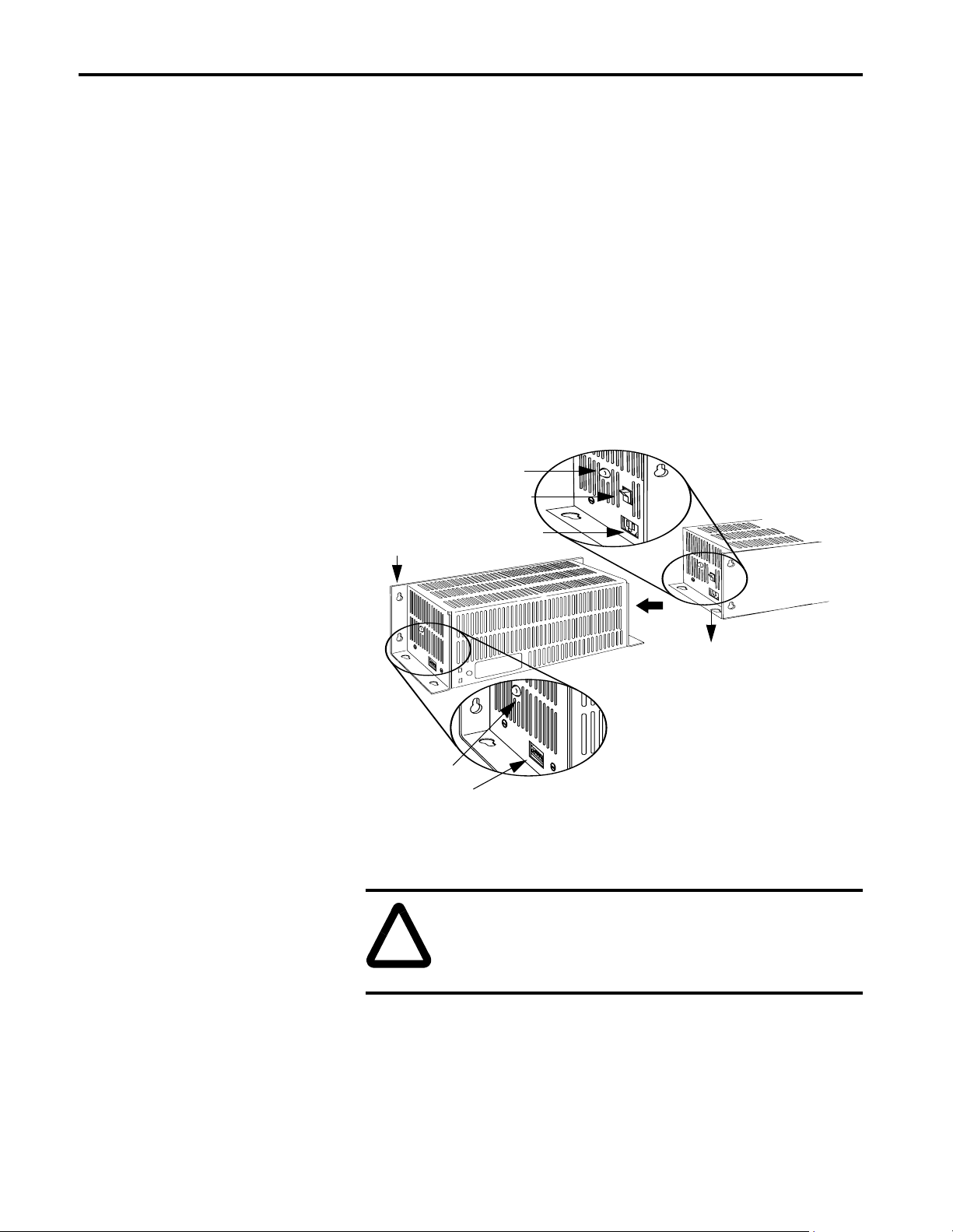
voltage selection switch
main power switch
IEC 3-pin connector
vertical mounting
horizontal mounting
LED power indicator
DeviceNet 5-pin open style connector
1. Place the power supply where you would like to mount it (either on a
shelf or vertically on a wa ll).
ATTENTION: Be certain that the power supply is
protected from liquids and condensation that might occur
through ventilation. Liquids or condensation could cause
damage to the product.
2. Attach the power supply to the selected mounting position by attaching
screws through the appropriate mounting flange.
1787-5.8 - February 1999
Page 3

DeviceNet Power Supply 3
3. Secure all necessary cords from the DeviceNet network in their
appropriate ports once the power supply is securely mounted.
ATTENTION: For alternate usage at an input of 230V ac
operation, the cord must be “SVT” type or equivalent with
an IEC320-C13 connector and appropriate grounded plug.
Cord must be 1.8m to 3.0m in length and rated for 2500W
(250V/10A).
Be certain that the voltage selection switch is set for proper
input voltage before application of main power.
4. Switch the main power switch to the on position to supply power to the
DeviceNet network.
Mounting Dimensions
9.5 mm (.375 in) diameter
for all mounting holes
9.5 mm (.375 in) diameter
for all mounting holes
126.9 mm
5 in
149.7 mm
5.9 in
This figure illustrates the correct mounting dimensions:
Vertical Mounting
304.8 mm
12 in
76.2 mm
3 in
Horizontal Mounting
98.6 mm
3.88 in
304.8 mm
12 in
Specifications Table 1 lists specifications for the DeviceNet power supply.
ATTENTION: This product may, under certain circumstances, develop hot surfaces during operation. Make sure
that proper precautions are taken to avoid damage to either
equipment or human operators.
1787-5.8 - February 1999
Page 4

Table 1: Specifications
Power
3-pin IEC Line Frequency 48-62 Hz
Connector
Fuse Class 2 type accepted
1
Turn-on Time
(with full load)
250msec max 95% of final
value
Size 5” x 6.5” x 11” Isolation output isolated from AC and
chassis ground
DC Connector Phoenix Combicon style 5-pin 5.08mm pitch
female and mating connector
DC Connector
Pins
Pin 1, 24V+; Pin 3, Chassis ground; Pin 5,
24V-
Operating Temperature 0 - 60
Storage
Temperature
°
C min 0 - 75° C with
30% derating at 75
32 - 140
°
F min 32 - 167° F
°
C
with 30% derating at 167
-40 - 85
-40- 185
°
C
°
F
°
Indicators LED power good indicator Humidity 95% non-condensing
Mounting Flange Electrostatic Discharge 4KV contact 8KV air
Enclosure Vented enclosure (indoor use) Vibration 2g, 10-500hz
Input Voltage 115V±10%
Shock 30g, 11ms half cycle
230V±10% selectable
Output Voltage 24V dc ± 1% Surge 4KV common mode,
2KV differential mode
F
Output Current Nameplate rating of 100VA to be consistent
Electrical Fast Transient 2KV
with NEC Class 2
Peak output currents 5.25 A
Ripple 250mV Radiated Immunity 10V/M 80 MHZ- 1GHZ
Load
Capacitance
Capability
1
Contact the manufacturer for information on replacing fuses for your power supply.
7000uF load Agency Certification (when
product or packaging is
marked)
DeviceNet is a trademark of Open Device Vendor Association (ODVA).
223 - M91 with T.I.L. No. CA 2A.
1310 class 2 power limited circuits
marked for all applicable directives
Publication 1787-5.8 - February 1999 PN 955138-62
Supersedes Publication xxxxxxx-xx - xxxxxxx-xx Copyright 1998 of Rockwell International Corporation. Printed in the U.S.A.
 Loading...