

Page 1

Installation Instructions
ControlNet IP67 Tap and Cable Assembly Kit
Installation Instructions
Cat. No.1786-TCT2BD1, -TPST2T, -TPRT2T
What’s in This Document
This document describes how to install the ControlNet IP67 Tap and Cable Assembly Kit.
The kit is available in three versions, as shown in the table below. All kits are identical, except
for the 1-meter drop cable.
for this version of the drop able order this kit
TNC to Straight BNC (TNC at tap body; BNC at node
end)
TNC to Straight TNC (TNC at tap body; TNC at node
end)
TNC to Right-angle TNC (TNC at tap body; TNC at node
end)
1786-TCT2BD1
1786-TPST2T
1786-TPRT2T
The kit is made up of a tap body and a 1-meter drop cable with overmolded connectors. The
drop cable has a TNC connector at the tap body end and either a BNC or TNC connector at
the ControlNet node end (depending on the version of the kit you order). The tap and cable
are rated to IP67 when mated to a sealed connector, which means they are water-tight.
Publication 1786-IN017B-EN-P - May 2004
Page 2

2 ControlNet IP67 Tap and Cable Assembly Kit Installation Instructions
Topic Page
Why Use Sealed Media Components? 5
Select a Location to Install Sealed Components 7
Install the Components 8
Terminate the Cable 9
Apply Heat-shrink Tubing 12
Connect ControlNet Segments in a Network Topology 14
Specifications 15
The modular design of the kit lets you disconnect the devices at either the end of the drop
cable, or at the tap port located on the tap body, without disrupting communications to the
rest of the network. You can permanently disconnect a tap from a device by installing a tap
dummy load (1786-TCAP) at the tap end of the drop cable.
TIP
IMPORTANT
The 1786-TCAP is compatible only with the 1786-TCT2BD1 drop
cable. You can use the 1786-TCT2BD1 drop cable with the
1786-TPRT2T tap body.
No more than one tap should be disconnected at the body at a time and
no more than 10% of the taps in a network may be terminated with tap
dummy loads (1786-TCAP). Failure to adhere to these rules may cause
excessive network errors and/or loss of network communications.
Publication 1786-IN017B-EN-P - May 2004
Page 3

ControlNet IP67 Tap and Cable Assembly Kit Installation Instructions 3
The kit also includes other items, such as a DIN rail mounting bracket and screws. See Table
1 below for a complete listing of the kit’s contents.
Table 1 ControlNet IP67 Tap and Cable Assembly Kit Contents
Catalog/
Publication
Number
1786-TPIP67 IP67 Tap Body (not sold separately) 1
1786-TPSDT2B TNC to Straight BNC Drop Cable
1786-TPRDT2T TNC to Right-angle TNC Drop Cable
1786-TPSDT2T TNC to Straight TNC Drop Cable
1786-TNCL10 TNC Plugs (bagged) 2
1799-BRKD DIN Rail Mounting Bracket 1
1786-IN017B-EN-P ControlNet IP67 Tap and Cable Assembly Kit Installation Instructions 1
Important User Information
Solid state equipment has operational characteristics differing from those of electromechanical equipment.
Safety Guidelines for the Application, Installation and Maintenance of Solid State Controls (Publication
SGI-1.1 available from your local Rockwell Automation sales office or online at
http://www.ab.com/manuals/gi) describes some important differences between solid state equipment and
hard-wired electromechanical devices. Because of this difference, and also because of the wide variety of
uses for solid state equipment, all persons responsible for applying this equipment must satisfy themselves
that each intended application of this equipment is acceptable.
In no event will Rockwell Automation, Inc. be responsible or liable for indirect or consequential damages
resulting from the use or application of this equipment.
The examples and diagrams in this manual are included solely for illustrative purposes. Because of the many
variables and requirements associated with any particular installation, Rockwell Automation, Inc. cannot
assume responsibility or liability for actual use based on the examples and diagrams.
No patent liability is assumed by Rockwell Automation, Inc. with respect to use of information, circuits,
equipment, or software described in this manual.
Reproduction of the contents of this manual, in whole or in part, without written permission of Rockwell
Automation, Inc. is prohibited.
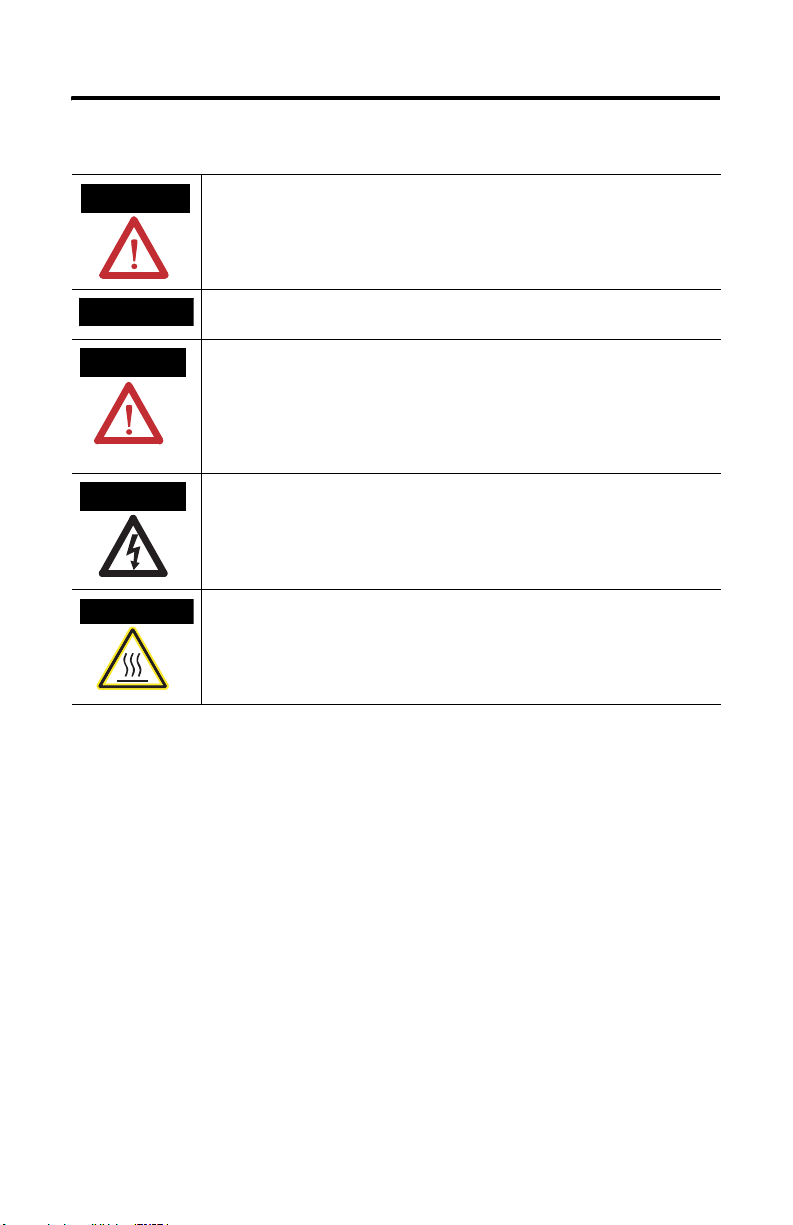
Throughout this manual we use notes to make you aware of safety considerations.
Description Qty.
One of the following 1-meter drop cables, depending on the version of
the kit you order (not sold separately):
DIN Rail Mounting Screws, #4-40 x .375
Pan Head, Cross Recess, Stainless Steel
Gray dust cap (for the drop cable) 1
1
2
Publication 1786-IN017B-EN-P - May 2004
Page 4
4 ControlNet IP67 Tap and Cable Assembly Kit Installation Instructions
Important User Information
WARNING
Identifies information about practices or circumstances that can cause an explosion in a
hazardous environment, which may lead to personal injury or death, property damage,
or economic loss.
IMPORTANT
ATTENTION
SHOCK HAZARD
BURN HAZARD
Identifies information that is critical for successful application and understanding of the
product.
Identifies information about practices or circumstances that can lead to personal injury
or death, property damage, or economic loss. Attentions help you:
• identify a hazard
• avoid a hazard
• recognize the consequence
Labels may be located on or inside the equipment to alert people that dangerous
voltage may be present.
Labels may be located on or inside the equipment to alert people that surfaces may be
dangerous temperatures.
Publication 1786-IN017B-EN-P - May 2004
Page 5
ControlNet IP67 Tap and Cable Assembly Kit Installation Instructions 5
Why Use Sealed Media Components?
Sealed media components are ControlNet taps and TNC connectors, rated to IP67, that are
suitable for use in harsh environments. IP67 is an industry-standard protection rating that
describes the degree of protection provided to the components within the IP67-rated device.
The IP67 rating means that the components are dust- and water-tight and water-immersible.
While the tap bodies and TNC connectors in all three versions of the kit are water-tight, the
BNC connector in the 1786-TCT2BD1 kit is not. Use the BNC version of the kit
(1786-TCT2BD1) in applications in which you can mount the BNC connector inside a
cabinet, or in another non-harsh environment. The sealed tap body contained in all versions
of the kit can be mounted in any environment requiring an IP67 rating.
ATTENTION
Be sure to mate or terminate all connections. The taps and drop
cables are rated to IP67 only when properly mated. Unterminated
connections could be a source of contamination. Use the gray dust
caps supplied in this kit to terminate unused connections. Never
install extra taps in IP67 environments because there is no way to seal
and protect the tap connections.
The IP67 rating is guaranteed only when you use Rockwell
Automation-supplied connectors and heat-shrink tubing.
Publication 1786-IN017B-EN-P - May 2004
Page 6

6 ControlNet IP67 Tap and Cable Assembly Kit Installation Instructions
Here are some example applications in which you would use the dust- and water-tight
ControlNet IP67 Tap and Cable Assembly kit:
ATTENTION
TIP
• robotic welding
• bottling
• automotive paint spray booth
• food processing (with washdown)
• metal processing
• wastewater treatment facility
• automotive manufacturing
• paper/pulp processing
IMPORTANT
Contact your Rockwell Automation representative for information on
chemical environments in which the taps are suited for use. Cutting
fluids and oils are not recommended for use with the taps.
Because TNC connectors have a greater operational vibration
tolerance than BNC connectors (10g vs. 2.5g), TNC connectors are
recommended for applications with a great deal of vibration, such as
stamping or automotive presses.
For information on how to plan and install your ControlNet cable
System, see the ControlNet Coax Media Planning and Installation Guide,
publication CNET-IN002.
Publication 1786-IN017B-EN-P - May 2004
Page 7

ControlNet IP67 Tap and Cable Assembly Kit Installation Instructions 7
Select a Location to Install Sealed Components
Use these guidelines to select where to install the components.
IMPORTANT
ATTENTION
IMPORTANT
• Be certain that the installation location is convenient for routing your cable and meets
the bend radius of the coax trunk line.
• Do not install sealed components so that the dropline cable is routed over any ac
power terminals on nearby modules.
ControlNet is an isolated system. Connectors and the shield must not
come in direct contact with a metal enclosure or other grounded
equipment. The 1786-BNC2TNC and 1786-TNCJI4 isolated bulkhead
connectors (available from Rockwell Automation) provide an isolation
from ground when properly installed.
Do not allow any metal portions of the tap, such as the universal
mounting bracket screws or connectors to contact any conductive
material. This contact could cause noise on the network.
Do not cut, lengthen, or substitute the drop cable supplied in this kit.
Doing so may diminish the integrity of your ControlNet network
connection.
Publication 1786-IN017B-EN-P - May 2004
Page 8

8 ControlNet IP67 Tap and Cable Assembly Kit Installation Instructions
Install the Components
1. Determine an adequate mounting location for the tap. Refer to the dimension
drawing shown below.
2.30 in. (5.8 cm)
1.42 in.
(3.6 cm)
1.21 in.
1.65 in.
(4.2 cm)
Front View
(3.1 cm)
2. To mount the tap to the DIN rail, use the hardware provided in the kit and attach as
shown in the following illustration.
Universal mounting bracket
.90 in.
(2.3 cm)
Side View
.49 in.
(1.2 cm)
.45 in.
(1.1 cm)
1 in.
(2.5 cm)
.60 in.
(1.5 cm)
Back View
.49 in.
(1.2 cm)
312889-M
Mount the universal
mounting bracket on the DIN
rails supplied in the kit.
DIN rail
31287-M
ATTENTION
Do not over-tighten the screws. Over-tightening the screws can
damage the tap. The applied torque should be 0.2-0.4 N-m (1-2
ft.-lbs).
3. To mount the tap through an enclosure wall, drill a hole of approximately 17.2 mm
for the 1786-TNCJI4 isolated bulkhead connector.
Publication 1786-IN017B-EN-P - May 2004
Page 9

ControlNet IP67 Tap and Cable Assembly Kit Installation Instructions 9
4. Attach the tap body to the isolated bulkhead connector using the 1786-TNCLP4
plug-to-plug adapter.
5. Attach the drop cable to the bulkhead connector. Attach the other end to the
ControlNet node.
1786-TCT2BD1
TNC tap
1786-TNCJI4 jack-to-jack isolated bulkhead
1 meter drop cable to device
1786-TNCLP4 plug-to-plug adapter
Terminate the Cable
IMPORTANT
IMPORTANT
To make IP67-approved crimps when installing connectors onto a cable,
order the ControlNet Coax Tool Kit, catalog number 1786-CTK). You
can also use this tool kit to make standard coax cables.
For more information on the ControlNet Coax Tool Kit, contact your
Rockwell Automation representative or refer to the ControlNet Coax
Media Planning and Installation Guide, publication CNET-IN002. You
can order a paper copy or view an electronic copy of this manual at
www.theautomationbookstore.com, or call 1-800-963-9548.
For more information on how to properly terminate cables, refer to the
ControlNet BNC installation training video on compact disk, publication
CNET-DM001. This CD is available from
www.theautomationbookstore.com or by calling 1-800-963-9548.
Do not cut, lengthen, or substitute the drop cable supplied in this kit.
Doing so may diminish the integrity of your ControlNet network
connection.
Publication 1786-IN017B-EN-P - May 2004
Page 10

10 ControlNet IP67 Tap and Cable Assembly Kit Installation Instructions
1. If your installation requires IP67-rated connectors, slide the heat-shrink tubing onto
the cable.
2. Place the crimp ferrule on to the cable.
3. Strip the cable using the 1786-CTK stripper tool.
4. Trim the center conductor to the required length as directed on the connector bag.
5. Push the flare tool onto the cable with a slight twisting motion (with sufficient inward
pressure to expand the braid).
41888
Push the flare/calibration tool gently and rotate
slightly onto the connector while applying pressure.
This will work the base of the connector underneath
the wire braid slowly.
6. Place the center pin over the center conductor.
IMPORTANT
Be certain that the center pin slips onto the center conductor completely.
The back shoulder of the center pin should be up against the white
insulation. If it is not, recheck the length of the center conductor.
Publication 1786-IN017B-EN-P - May 2004
41890
Page 11

ControlNet IP67 Tap and Cable Assembly Kit Installation Instructions 11
7. With the center pin in place, use the crimp tool to crimp the pin into place.
The smaller hexagonal crimping notch is for crimping
the center pin onto the center connector.
41903
Check for braid strands that could
cause a short to center conductor.
8. Slide the ControlNet connector onto the cable. Push the connector body on tight
until the center pin tip is flush with the inner ground ring.
9. Slide the crimp ferrule over the three outer shields and connector base until it meets
the shoulder on the connector.
10. Using the crimp tool, crimp the ferrule. Position the crimp tool on the ferrule as close
as possible to the connector base and ferrule meeting line. Press the tool tightly
around the ferrule until the crimp tool allows release.
TIP
TIP
The larger hexagonal crimping notch is for crimping the ferrule which
holds the connector to the cable.
Many network problems are due to improperly installed connectors.
You should have tight-fitting connectors on the ends of all your
cables. Pull the connector to verify that it is attached. If it is loose or
comes off, snip off the connector and install a new one. The
connector should withstand a minimum 60lbs pull force if properly
installed.
Publication 1786-IN017B-EN-P - May 2004
Page 12

12 ControlNet IP67 Tap and Cable Assembly Kit Installation Instructions
11. Inspect the cable at the TNC connector end for any loose cable braids. Loose braids may
cause voids in the heat-shrink tubing.
Sometimes strands will be too long and
protrude out of the ferrule. Using the
Exacto blade, trim the excess length off
flush with the connector body.
12. Place the heat-shrink tubing with heat-active glue (provided in the IP67 Tap and Cable
Assembly Kit) over the TNC connector body and cable.
IMPORTANT
Use only the ACUM heat-shrink tubing provided in the kit. Do not
substitute other types of heat-shrink tubing. Substitutions may cause a
loss of the IP67 rating.
Apply Heat-shrink Tubing
1. Follow these guidelines when heating the tubing:
ATTENTION
a. Place the tubing against the shoulder of the TNC connector.
b. Allow the heat gun to come to a temperature of between 110 and 160 degrees Celsius.
c. Hold the cable assembly approximately 2 inches away from the heat exhaust area of
the heat gun while shrinking the tubing.
d. Continuously rotate the cable assembly around the heat exhaust area of the heat gun.
The entire process should take about 4 minutes.
Be careful when using heat guns. High temperatures can lead to burns,
risk of fire, or other property damage.
Publication 1786-IN017B-EN-P - May 2004
Page 13

ControlNet IP67 Tap and Cable Assembly Kit Installation Instructions 13
e. Inspect the heat-shrink tubing to ensure that there are no voids where the glue has
incompletely melted. Voids could cause a loss of the IP67 rating.
Place the tubing against
the shoulder of the TNC
connector
Ensure that there are no
voids where glue has
incompletely melted
31297-M
2. Attach the trunk line to the tap. Tighten the trunk-line connector to 1 N-m (0.74
ft.-lbs.).
IMPORTANT
Be sure to install the dust cap on any unused connectors. Doing so will:
• prohibit the center conductor or the outer conductor from
inadvertently shorting to ground during installation
• provide partial environmental protection if a tap is left disconnected
for a prolonged time
Publication 1786-IN017B-EN-P - May 2004
Page 14

14 ControlNet IP67 Tap and Cable Assembly Kit Installation Instructions
Connect ControlNet Segments in a Network Topology
See the following illustration for a sample network topology installation.
1786-RG6
1786-BNC2TNC
1786-TNCL10
1786-TNCL10
1786-RG6
IP67-compliant
ControlNet device
1786-BNC/B
1786-BNC/B
1786-TNCL10
1786-TPST2T,
-TPRT2T
1786-TPS
1786-BNC/B
1786-RG6
1
TNC to BNC
drop cable
1786-BNC2TNC
1786-BNC/B
1786-RG6
1786-TNCL10
1786-TNCLP4
1786-TCT2BD1
TNC to BNC
drop cable
1786-TCT2BD1
1
TNC to BNC
drop cable
1786-TCT2BD1
1786-TNCLXTL4
1
1
1786-TNCLP4
1786-TNCJI4
TNC to BNC
drop cable
Wire Gland
(not supplied by
Rockwell Automation)
31290-M
1 Although the arrow in this illustration points to the tap body, the catalog number called out corresponds to the appropriate
ControlNet Tap and Cable Assembly Kit.
TIP
Except where indicated in the illustration above, use only the
hardware that we provide with the connector. Other hardware can
diminish the integrity of your connection. For catalog numbers shown
in the illustration above but not supplied in the kit, contact your local
Rockwell Automation distributor.
Publication 1786-IN017B-EN-P - May 2004
Page 15

Specifications
ControlNet IP67 Tap and Cable Assembly Kit Installation Instructions 15
operational temperature IEC 60068-2-1 (Test Ad, Operating Cold),
storage temperature IEC 60068-2-2 (Test Ab, Un-packaged Non-operating Cold),
relative humidity IEC 60068-2-30 (Test Db, Un-packaged Non-operating Damp Heat):
vibration IEC 60068-2-6 (Test Fc, Operating):
operating shock IEC 60068-2-27 (Test Ea, Unpackaged Shock):
non-operating shock IEC 60068-2-27 (Test Ea, Unpackaged Shock):
IEC 60068-2-2 (Test Bd, Operating Dry Heat),
IEC 60068-2-14 (Test Nb, Operating Thermal Shock):
-20 to 70 °C (-4 to 158 °F)
IEC 60068-2-2 (Test Bb, Un-packaged Non-operating Dry Heat),
IEC 60068-2-14 (Test Na, Un-packaged Non-operating Thermal Shock):
-40 to 85 °C (-40 to 185 °F)
5 to 95% non-condensing
10g @ 10-500Hz
30g
50g
Publication 1786-IN017B-EN-P - May 2004
Page 16

Rockwell Automation Support
Rockwell Automation provides technical information on the web to assist you in using our
products. At http://support.rockwellautomation.com, you can find technical manuals, a
knowledge base of FAQs, technical and application notes, sample code and links to software
service packs, and a MySupport feature that you can customize to make the best use of these
tools.
For an additional level of technical phone support for installation, configuration and
troubleshooting, we offer TechConnect Support programs. For more information, contact
your local distributor or Rockwell Automation representative, or visit
http://support.rockwellautomation.com.
Installation Assistance
If you experience a problem with a hardware module within the first 24 hours of installation,
please review the information that's contained in this manual. You can also contact a special
Customer Support number for initial help in getting your module up and running:
United States 1.440.646.3223
Outside United
States
Monday – Friday, 8am – 5pm EST
Please contact your local Rockwell Automation representative for any
technical support issues.
New Product Satisfaction Return
Rockwell tests all of our products to ensure that they are fully operational when shipped from
the manufacturing facility. However, if your product is not functioning and needs to be
returned:
United States Contact your distributor. You must provide a Customer Support case number
Outside United
States
(see phone number above to obtain one) to your distributor in order to
complete the return process.
Please contact your local Rockwell Automation representative for return
procedure.
Publication 1786-IN017B-EN-P - May 2004 PN 957899-44
Supersedes Publica tion 1786-IN017A-EN-P - Ma rch 2002 Copyright © 2004 Rockwell Automation, Inc. A ll rights reserved. Printed in the U.S.A.
 Loading...