

Page 1
Installation Instructions
ControlNet Dual Copper Repeater Module
Catalog Number 1786-RPCD
This document describes how to install and apply the 1786-RPCD dual copper repeater
module.
Topi c : Page:
European Hazardous Location Approval 4
North American Hazardous Location Approval 6
About the Dual Copper Repeater Module 7
Mount the Repeater Module 9
Use Trunk Line Terminators 12
Remove the Repeater Module from the DIN Rail 13
Connect the Repeater Module 13
Understand Common Topologies 15
Understand Constraints of the Coax Segment 17
Status Indicators 19
Mounting Dimensions 20
Specifications 20
Publication 1786-IN001B-EN-P - May 2004
Page 2
2 ControlNet Dual Copper Repeater Module
Important User Information
Solid state equipment has operational characteristics differing from those of electromechanical equipment.
Safety Guidelines for the Application, Installation and Maintenance of Solid State Controls (Publication
SGI-1.1 available from your local Rockwell Automation sales office or online at
http://www.ab.com/manuals/gi) describes some important differences between solid state equipment and
hard-wired electromechanical devices. Because of this difference, and also because of the wide variety of
uses for solid state equipment, all persons responsible for applying this equipment must satisfy themselves
that each intended application of this equipment is acceptable.
In no event will Rockwell Automation, Inc. be responsible or liable for indirect or consequential damages
resulting from the use or application of this equipment.
The examples and diagrams in this manual are included solely for illustrative purposes. Because of the many
variables and requirements associated with any particular installation, Rockwell Automation, Inc. cannot
assume responsibility or liability for actual use based on the examples and diagrams.
No patent liability is assumed by Rockwell Automation, Inc. with respect to use of information, circuits,
equipment, or software described in this manual.
Reproduction of the contents of this manual, in whole or in part, without written permission of Rockwell
Automation, Inc. is prohibited.
Throughout this manual we use notes to make you aware of safety considerations.
WARNING
Identifies information about practices or circumstances that can cause an explosion in a
hazardous environment, which may lead to personal injury or death, property damage,
or economic loss.
IMPORTANT
ATTENTION
SHOCK HAZARD
BURN HAZARD
Identifies information that is critical for successful application and understanding of the
product.
Identifies information about practices or circumstances that can lead to personal injury
or death, property damage, or economic loss. Attentions help you:
• identify a hazard
• avoid a hazard
• recognize the consequence
Labels may be located on or inside the equipment to alert people that dangerous
voltage may be present.
Labels may be located on or inside the equipment to alert people that surfaces may be
dangerous temperatures.
Publication 1786-IN001B-EN-P - May 2004
Page 3
ControlNet Dual Copper Repeater Module 3
ATTENTION
Environment and Enclosure
This equipment is intended for use in a Pollution Degree 2 industrial
environment, in overvoltage Category II applications (as defined in IEC
publication 60664-1), at altitudes up to 2000 meters without derating.
This equipment is considered Group 1, Class A industrial equipment
according to IEC/CISPR Publication 11. Without appropriate
precautions, there may be potential difficulties ensuring electromagnetic
compatibility in other environments due to conducted as well as radiated
disturbance.
This equipment is supplied as “open type” equipment. It must be
mounted within an enclosure that is suitably designed for those specific
environmental conditions that will be present and appropriately designed
to prevent personal injury resulting from accessibility to live parts. The
interior of the enclosure must be accessible only by the use of a tool.
Subsequent sections of this publication may contain additional
information regarding specific enclosure type ratings that are required to
comply with certain product safety certifications.
NOTE: See NEMA Standards publication 250 and IEC publication
60529, as applicable, for explanations of the degrees of protection
provided by different types of enclosure. Also, see the appropriate
sections in this publication, as well as the Allen-Bradley publication
1770-4.1 (“Industrial Automation Wiring and Grounding Guidelines”),
for additional installation requirements pertaining to this equipment.
ControlNet is a trademark of ControlNet International, Inc.
Publication 1786-IN001B-EN-P - May 2004
Page 4
4 ControlNet Dual Copper Repeater Module
ATTENTION
ATTENTION
Preventing Electrostatic Discharge
This equipment is sensitive to electrostatic discharge, which can cause
internal damage and affect normal operation. Follow these guidelines
when you handle this equipment:
• Touch a grounded object to discharge potential static.
• Wear an approved grounding wriststrap.
• Do not touch connectors or pins on component boards.
• Do not touch circuit components inside the equipment.
• If available, use a static-safe workstation.
• When not in use, store the equipment in appropriate static-safe
packaging.
This product is grounded through the DIN rail to chassis ground. Use
zinc plated yellow-chromate steel DIN rail to assure proper grounding.
The use of other DIN rail materials (e.g., aluminum, plastic, etc.) that can
corrode, oxidize, or are poor conductors, can result in improper or
intermittent grounding.
European Hazardous Location Approval
If you install the module in a European Zone 2 location, consider:
ATTENTION
Publication 1786-IN001B-EN-P - May 2004
European Zone 2 Certification (The following applies when the
product bears the EEx Marking)
This equipment is intended for use in potentially explosive atmospheres
as defined by European Union Directive 94/9/EC.
The LCIE (Laboratoire Central des Industries Electriques) certifies that
this equipment has been found to comply with the Essential Health and
Safety Requirements relating to the design and construction of Category 3
equipment intended for use in potentially explosive atmospheres, given in
Annex II to this Directive. The examination and test results are recorded
in confidential report No. 28 682 010.
Compliance with the Essential Health and Safety Requirements has been
assured by compliance with EN 50021.
Page 5
ControlNet Dual Copper Repeater Module 5
IMPORTANT
This equipment is not resistant to sunlight or other sources of UV
radiation.
The secondary of a current transformer shall not be open-circuited when
applied in Class I, Zone 2 environments.
Equipment of lesser Enclosure Type Rating must be installed in an
enclosure providing at least IP54 protection when applied in Class I, Zone
2 environments.
This equipment shall be used within its specified ratings defined by
Allen-Bradley.
Provision shall be made to prevent the rated voltage from being exceeded
by transient disturbances of more than 40% when applied in Class I, Zone
2 environments.
Publication 1786-IN001B-EN-P - May 2004
Page 6
6 ControlNet Dual Copper Repeater Module
North American Hazardous Location Approval
The following information applies when
operating this equipment in hazardous
locations:
Products marked “CL I, DIV 2, GP A, B, C, D” are
suitable for use in Class I Division 2 Groups A, B, C, D,
Hazardous Locations and nonhazardous locations only.
Each product is supplied with markings on the rating
nameplate indicating the hazardous location
temperature code. When combining products within a
system, the most adverse temperature code (lowest
“T” number) may be used to help determine the
overall temperature code of the system. Combinations
of equipment in your system are subject to
investigation by the local Authority Having
Jurisdiction at the time of installation.
WARNING
EXPLOSION HAZARD
• Do not disconnect equipment
unless power has been
removed or the area is known
to be nonhazardous.
• Do not disconnect
connections to this
equipment unless power has
been removed or the area is
known to be nonhazardous.
Secure any external
connections that mate to this
equipment by using screws,
sliding latches, threaded
connectors, or other means
provided with this product.
• Substitution of components
may impair suitability for
Class I, Division 2.
• If this product contains
batteries, they must be
changed only in an area
known to be nonhazardous.
Informations sur l’utilisation de cet équipement en
environnements dangereux:
Les produits marqués "CL I, DIV 2, GP A, B, C, D" ne
conviennent qu’à une utilisation en environnements de
Classe I Division 2 Groupes A, B, C, D dangereux et non
dangereux. Chaque produit est livré avec des marquages
sur sa plaque d’identification qui indiquent le code de
température pour les environnements dangereux.
Lorsque plusieurs produits sont combinés dans un
système, le code de température le plus défavorable
(code de température le plus faible) peut être utilisé pour
déterminer le code de température global du système.
Les combinaisons d’équipements dans le système sont
sujettes à inspection par les autorités locales qualifiées
au moment de l’installation.
AVERTISSEMENT
RISQUE D’EXPLOSION
• Couper le courant ou
s’assurer que
l’environnement est
classé non dangereux
avant de débrancher
l'équipement.
• Couper le courant ou
s'assurer que
l’environnement est
classé non dangereux
avant de débrancher les
connecteurs. Fixer tous
les connecteurs externes
reliés à cet équipement à
l'aide de vis, loquets
coulissants, connecteurs
filetés ou autres moyens
fournis avec ce produit.
• La substitution de
composants peut rendre
cet équipement inadapté
à une utilisation en
environnement de Classe
I, Division 2.
• S’assurer que
l’environnement est
classé non dangereux
avant de changer les
piles.
Publication 1786-IN001B-EN-P - May 2004
Page 7
ControlNet Dual Copper Repeater Module 7
WARNING
WARNING
About the Dual Copper Repeater Module
Use this copper repeater module when the:
• design of the network requires a hub-based topology
• segment requires a greater copper distance
• design requires an isolated segment
• number of nodes requires the use of repeaters (refer to Understand Constraints of the
Coax Segment on page 1-17)
If you insert or remove the module while backplane power is
on, an electrical arc can occur. This could cause an explosion
in hazardous location installations.If you insert or remove the
module while backplane power is on, an electrical arc can oc
cur. This could cause an explosion in hazardous location installations.
Be sure that power is removed or the area is nonhazardous before proceeding.
If you connect or disconnect the communications cable with
power applied to this module or any device on the network, an
electrical arc can occur. This could cause an explosion in haz
ardous location installations.
-
-
The copper repeater module allows multiple 1000m copper segments to be attached to a
repeater adapter (1786-RPA). See pages15-18 for topology examples and segment length
constraints.
The module provides two copper channels and activity status indicators for each channel.
Publication 1786-IN001B-EN-P - May 2004
Page 8
8 ControlNet Dual Copper Repeater Module
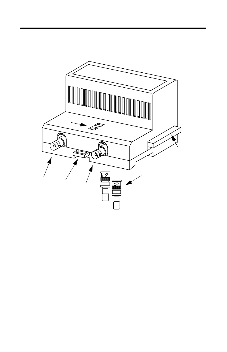
The figure below identifies the components of the module:
The left side of the
module (not shown
here) also contains a
backplane connector.
Indicators
Right-side backplane
connector with
protective cover
Channel 1
coax port
Module
locking tab
Channel 2
coax port
Publication 1786-IN001B-EN-P - May 2004
75 Ω BNC Trunk line terminators
(1786-XT)
Important:You must terminate
unused channels to maintain the
integrity of your network.
42210
Page 9

Mount the Repeater Module
To mount the module on the DIN rail:
ControlNet Dual Copper Repeater Module 9
ATTENTION
1. Position the module on the 35×7.5mm DIN rail (Allen-Bradley part number
199-DRI; 46277-3; EN 50022) at a 30° angle.
IMPORTANT
This product is grounded through the DIN rail to chassis ground.
Use zinc plated yellow-chromate steel DIN rail to assure proper
grounding. The use of other DIN rail materials (e.g., aluminum,
plastic, etc.) that can corrode, oxidize, or are poor conductors, can
result in improper or intermittent grounding.
To ensure proper operation of the 1786-RPCD repeater module, you
must position the 1786-RPCD module to the left of any 1786-RPFRL or
1786-RPFRXL repeater modules in your configuration.
30074-M
2. Hook the module lip (on the rear of the module) onto the top of the DIN rail and
rotate the module onto the rail.
3. Press the module down to the DIN rail until the module is flush with the rail.
The locking tab should snap into position and lock the module onto the DIN rail. If
the tab does not snap into position, follow step 4. If the tab does snap into position,
go to step 5.
Publication 1786-IN001B-EN-P - May 2004
Page 10

10 ControlNet Dual Copper Repeater Module
4. Use a screwdriver to move the locking tab down while you press the module flush
onto the DIN rail. Release the locking tab to secure the module in place. If necessary,
push up on the locking tab to secure the module in place.
30076-M
Publication 1786-IN001B-EN-P - May 2004
30074-M
Page 11

ControlNet Dual Copper Repeater Module 11
5. Once you attach the modules to the DIN rail, slide the modules to the left to attach to
the repeater adapter or another repeater module.
You must use a DIN rail end anchor on the
right side of the copper module if it is the
right-most module.
31493-M
IMPORTANT
Because the 1786-RPCD repeater module is part of the modular family of
ControlNet repeaters, you must use the 1786-RPA repeater adapter to
supply power and coordinate the modules’ TX and RX function.
To ensure proper operation of the 1786-RPCD repeater module, you
must position the 1786-RPCD module to the left of any 1786-RPFRL or
1786-RPFRXL repeater modules in your configuration.
IMPORTANT
You can attach a maximum of four repeater modules (1786-RPCD) to a
repeater adapter (1786-RPA). If you exceed the repeater limit, you may
cause damage to the repeater adapter and repeaters. Four repeaters can
draw up to 1.6A @ 5V dc in power consumption. If you exceed this
power limit, you may cause damage to the repeater adapter and repeaters.
6. Use DIN rail end anchors to secure the units together.
ATTENTION
Be certain that you secure the adapter and repeater modules together with
DIN rail end anchors. Failure to do so may result in loss of communication
and/or damage to modules.
7. Connect terminators to unused channels as shown in Use Trunk Line Terminators on
page 12.
Publication 1786-IN001B-EN-P - May 2004
Page 12

12 ControlNet Dual Copper Repeater Module
8. Connect the module wiring as shown in Connect the Module For Coax Channels 1
and 2 on page 14.
9. Ground your DIN rail in accordance with local codes using a minimum #14 AWG
wire. See page
12 for DIN rail ground wire example.
Use Trunk Line Terminators
When you are not connecting a trunk line to a channel on the 1786-RPCD repeater module,
connect a 75
Ω terminating resistor (1786-XT) to maintain the integrity of your network.
Be certain to ground the DIN rail
with a minimum #14 AWG wire.
The left side of the module
(not shown here) also
contains a backplane
connector.
If: Then:
you are not going to use a channel keep the ter minator on an unused channel for optimal
you connect another repeater module or repeater
adapter to the right backplane connector
you are not going to connect a module to the right
backplane connector
the module is in the right-most position attach a DIN rail end anchor
Terminator
network performance
remove the protective backplane cap and save the
cap for future use
leave the backplane cap attached
Protective
backplane cap
DIN rail
31494-M
Publication 1786-IN001B-EN-P - May 2004
Page 13

ControlNet Dual Copper Repeater Module 13
Remove the Repeater Module from the DIN Rail
To remove the module from the DIN rail, do the following:
1. Insert a screwdriver into the module locking tab.
2. Gently pry up on the locking tab.
31491-M
The module should detach from the DIN rail. If the module does not unlock, try
more pressure while you pry up on the locking tab with the screwdriver.
Connect the Repeater Module
TIP
If you need to connect only one coax channel on the 1786-RPCD module,
you can use either channel 1 or channel 2. Both channels 1 and 2 operate
identically and can be used interchangeably.
Be sure to terminate the unused channel with a 75-Ω terminating resistor
(1786-XT).
Publication 1786-IN001B-EN-P - May 2004
Page 14

14 ControlNet Dual Copper Repeater Module
Connect the Module For Coax Channels 1 and 2
1. Connect the ControlNet tap to port #1.
a. Align the knob of the BNC cable connector with the locks of the BNC module
connector, and insert the connector into channel 1.
Tap
BNC connector
75 Ω
terminator
31492-M
b. Twist the BNC connector until the bayonet lug is locked into place.
2. To connect channel 2, repeat Step 1 for channel 2. If channel 2 is not used, connect a
Ω terminating resistor (1786-XT) to the port labeled channel 2.
75-
3.
For examples of properly connected channels, refer to the example topologies on pages 15
through 17.
Publication 1786-IN001B-EN-P - May 2004
Page 15

ControlNet Dual Copper Repeater Module 15
Understand Common Topologies
The following topologies show how you can use the module.
Series Topology
The following figure shows the 1786-RPCD wired in series. This topology can be used to
extend the trunk line.
Connect 1786-RPA repeater adapter to a 24V dc
PLC
Class 2 power supply.
1786-RPA 1786-RPA
1786-RPCD
REPEATER DUAL COPPER MODULE
CH 1 CH 2
1786-RPCD
1794-ACNR15
1786-RPCD
REPEATER DUAL COPPER MODULE
CH 1 CH 2
1794-ACNR15
1786-RPCD
31484-M
Publication 1786-IN001B-EN-P - May 2004
Page 16

16 ControlNet Dual Copper Repeater Module
Star Topology
The following figure shows a star configuration that supports 16 usable segments. The two
1786-RPA repeater adapters create a central hub with the 1786-RPCD modules forming 16
segments
.
16 segments, 2 1786-RPA repeater adapters in series
with a maximum of 4 1786-RPCD modules per repeater adapter.
1786-RPA
1786-RPA
1786-RPCD
Segment 1
1786-RPCD
Segment 9
REPEATER DUAL COPPER MODULE
REPEATER DUAL COPPER MODULE
1786-RPCD
1786-RPCD
1786-RPCD
REPEATER DUAL COPPER MODULE
1786-RPCD
REPEATER DUAL COPPER MODULE
1786-RPCD
1786-RPCD
1786-RPCD
REPEATER DUAL COPPER MODULE
1786-RPCD
REPEATER DUAL COPPER MODULE
1786-RPCD
1786-RPCD
1786-RPCD
REPEATER DUAL COPPER MODULE
Segment 8
1786-RPCD
REPEATER DUAL COPPER MODULE
1786-RPCD
to
1786-RPCD
Segment 16
Publication 1786-IN001B-EN-P - May 2004
31485-M
Page 17

ControlNet Dual Copper Repeater Module 17
Redundant Topology
Use redundant media when you need module and media redundancy. With redundant media,
the channel-to-channel skew travel time difference must be less than 1.6
µ s.
TIP
Redundant media can be used with series and star topologies. You
cannot use redundant media with ring redundant topology.
For more information on redundant topology, refer to the ControlNet Fiber Media Planning
and Installation Guide, publication CNET-IN001.
CH A
CH B
1786-RPA 1786-RPA
1786-RPCD
CH1
1786-RPA 1786-RPA
CH2
1786-RPCD
CH1
1786-RPA
CH2
1786-RPCD
CH1
1786-RPA
CH2
1786-RPCD
CH1
1786-RPCD
CH2
CH1
1786-RPCD
CH2
CH2
CH1
1794-ACNR15
CH A
CH B
31497-M
Understand Constraints of the Coax Segment
The total allowable length of a segment containing standard RG-6 quad shield coaxial cable
depends upon the number of taps in your segment. There is no minimum trunk-cable section
length requirement.
The maximum allowable total length of a segment is 1,000m (3,280ft) with two taps
connected. Each additional tap decreases the maximum length of the segment by 16.3m
(53ft). The maximum number of taps allowed on a segment is 48 with a maximum length of
250m (820ft).
Publication 1786-IN001B-EN-P - May 2004
Page 18

18 ControlNet Dual Copper Repeater Module
Figure 1 Maximum segment length (assumes you are using 1786-RG6 coax
cable)
1000 (3280)
m
h
750 (2460)
t
g
n
e
500 (1640)
l
t
n
250 (820)
e
m
g
e
s
2
number of taps
maximum allowable segment length = 1000m (3280ft) - 16.3m (53.4ft) X [number of taps - 2]
32
16
48
30014-M
EXAMPLE
If your segment requires 10 taps, the maximum segment length is:
1000m (3280ft) - 16.3m (53.4ft) x [10 - 2]
1000m (3280ft) - 130.4m (427.7ft) = 869.6m (2852.8ft)
The total trunk-cable length or number of taps can be increased by
installing repeaters on the segment. This creates another segment.
The amount of high-flex RG-6 cable (1786-RG6F) you can use in a
system is less than the amount of standard RG-6 cable, so you should
keep high-flex cable use to a minimum. Use BNC bullet connectors to
isolate areas that require high-flex RG-6 cable from areas that require
standard RG-6 cable; this allows the high-flex RG-6 section to be
replaced before flexture life is exceeded.
For more information in the installation of a coax segment, see publication CNET-IN002,
ControlNet Coax Media Planning and Installation Guide.
Publication 1786-IN001B-EN-P - May 2004
Page 19

ControlNet Dual Copper Repeater Module 19
Status Indicators
The figure below identifies indicators on the module:
Channel 1 status
Channel 2 status
The table below defines Channel 1 and Channel 2 status indicators.
Status Indicator: Probable Cause:
Off No power or module faulted
Green Channel operational
Flashing Green/Off No data activity on associated channel
31489-M
Publication 1786-IN001B-EN-P - May 2004
Page 20

20 ControlNet Dual Copper Repeater Module
Mounting Dimensions
The figure below shows the dimensions for mounting the module.
4.44in
(111mm)
4.0in
(100mm)
2.76in
(69mm)
3.6in
(90mm)
4.048in
(101.2mm)
Specifications
Specification Value
Operational Temperature IEC 60068-2-1 (Test Ad, Operating Cold),
Storage Temperature IEC 60068-2-1 (Test Ab, Un-packaged Non-operating Cold),
Relative Humidity IEC 60068-2-30 (Test Db, Un-packaged Non-operating Damp Heat):
Vibration IEC 60068-2-6 (Test Fc, Operating):
Operating Shock IEC 60068-2-27 (Test Ea, Unpackaged Shock):
Non-operating Shock IEC 60068-2-27 (Test Ea, Unpackaged Shock):
IEC 60068-2-2 (Test Bd, Operating Dry Heat),
IEC 60068-2-14 (Test Nb, Operating Thermal Shock):
0 to 60 ° C (32 to 140 ° F)
IEC 60068-2-2 (Test Bb, Un-packaged Non-operating Dry Heat),
IEC 60068-2-14 (Test Na, Un-packaged Non-operating Thermal Shock):
-40 to 85 ° C (-40 to 185 ° F)
5 to 95% non-condensing
5g@10 - 500Hz
30g
50g
31495-M
Publication 1786-IN001B-EN-P - May 2004
Page 21

ControlNet Dual Copper Repeater Module 21
Specification Value
Emissions CISPR 11:
ESD Immunity IEC 61000-4-2:
Radiated RF Immunity IEC 61000-4-3:
EFT/B Immunity IEC 61000-4-4:
Surge Transient Immunity IEC 61000-4-5:
Conducted RF Immunity IEC 61000-4-6:
Enclosure Type Rating None (open-style)
Power Consumption 499 mA @ 5V dc Class 2 from 1786-RPA
Power Dissipation 2W
Isolation Voltage
(continuous-voltage
withstand rating)
Group 1, Class A
4kV contact discharges
8kV air discharges
10V/m with1kHz sine-wave 80% AM from30MHz to 1000MHz
10V/m with 200Hz 50% Pulse 100% AM at 900MHz
±2kV at 5kHz on communications ports
±2kV line-earth (CM) on shielded ports
10Vrms with 1kHz sine-wave 80% AM from 150kHz to 80MHz
50 V continuous
Publication 1786-IN001B-EN-P - May 2004
Page 22

22 ControlNet Dual Copper Repeater Module
Specification Value
Wiring Category
1
Certifications (when product
is marked)
1 - on communications ports
UL Listed Industrial Control Equipment
CSA Certified Process Control Equipment
CSA Certified Process Control Equipment for Class I, Division 2 Group A,B,C,D
Hazardous Locations
CE2 - European Union 89/336/EEC EMC Directive, compliant with:
EN 50082-2; Industrial Immunity
EN 61326; Meas./Control/Lab., Industrial Requirements
EN 61000-6-2; Industrial Immunity
EN 61000-6-4; Industrial Emissions
C-tick2 - Australian Radiocommunications Act, compliant with:
AS/NZS CISPR 11; Industrial Emissions
EEx2 - European Union 94/9/EC ATEX Directive, compliant with:
EN 50021; Potentially Explosive Atmospheres, Protection “n” (Zone 2)
CI - ControlNet International conformance tested to ControlNet specifications
1
Use this Conductor Category information for planning conductor routing. Refer to Publication 1770-4.1, “Industrial
Automation Wiring and Grounding Guidelines”.
2
See the Product Certification link at www.ab.com for Declarations of Conformity, Certificates, and other certification details.
Publication 1786-IN001B-EN-P - May 2004
Page 23

Notes:
ControlNet Dual Copper Repeater Module 23
Publication 1786-IN001B-EN-P - May 2004
Page 24

Rockwell Automation Support
Rockwell Automation provides technical information on the web to assist you in using our
products. At http://support.rockwellautomation.com, you can find technical manuals, a
knowledge base of FAQs, technical and application notes, sample code and links to software
service packs, and a MySupport feature that you can customize to make the best use of these
tools.
For an additional level of technical phone support for installation, configuration and
troubleshooting, we offer TechConnect Support programs. For more information, contact
your local distributor or Rockwell Automation representative, or visit
http://support.rockwellautomation.com.
Installation Assistance
If you experience a problem with a hardware module within the first 24 hours of installation,
please review the information that's contained in this manual. You can also contact a special
Customer Support number for initial help in getting your module up and running:
United States 1.440.646.3223
Outside United
States
Monday – Friday, 8am – 5pm EST
Please contact your local Rockwell Automation representative for any
technical support issues.
New Product Satisfaction Return
Rockwell tests all of our products to ensure that they are fully operational when shipped from
the manufacturing facility. However, if your product is not functioning and needs to be
returned:
United States Contact your distributor. You must provide a Customer Support case number
Outside United
States
(see phone number above to obtain one) to your distributor in order to
complete the return process.
Please contact your local Rockwell Automation representative for return
procedure.
Publication 1786-IN001B-EN-P - May 2004 PN 957899-02
Supersedes Pub lication 1786-IN001A-EN -P - Feb 2000 Copyright © 20 04 Rockwell Automatio n, Inc. All rights reser ved. Printed in the U.S.A.
 Loading...