

Page 1
SoftLogix
TM
Motion
Card
(Cat.No. 1784-PM02AE, -PM16SE)
Setup and Configuration
Manual
Page 2
Important User Information
Because of the variety of uses for the products described in this publication,
those responsible for the application and use of this control equipment must
satisfy themselves that all necessary steps have been taken to assure that each
application and use meets all performance and safety requirements, including
any applicable laws, regulations, codes and standards.
The illustrations, charts, sample programs and layout examples shown in this
guide are intended solely for purposes of example. Since there are many
variables and requirements associated with any particular installation,
Allen-Bradley does not assume responsibility or liability (to include intellectual
property liability) for actual use based upon the examples shown in this
publication.
Allen-Bradley publication SGI-1.1, Safety Guidelines for the Application, Installation
and Maintenance of Solid-State Control (available from your local Allen-Bradley
office), describes some important differences between solid-state equipment
and electromechanical devices that should be taken into consideration when
applying products such as those described in this publication.
Reproduction of the contents of this copyrighted publication, in whole or part,
without written permission of Rockwell Automation, is prohibited.
Throughout this manual we use notes to make you aware of safety
considerations:
WARNING
Identifies information about practices or circumstances that
can lead to personal injury or death, property damage or
economic loss
!
Attention statements help you to:
• identify a hazard
• avoid a hazard
• recognize the consequences
IMPORTANT
Allen-Bradley is a trademark of Rockwell Automation
RSLogix, SoftLogix, Ultra3000, Ultra5000, and Kinetix 6000 are all trademarks of Rockwell Automation
SERCOS interface is a trademark of the Interests group SERCOS interface e.V. of Stuttgart, Germany
Identifies information that is critical for successful
application and understanding of the product.
Page 3

European Communities (EC) Directive Compliance
If this product has the CE mark it is approved for installation within the
European Union and EEA regions. It has been designed and tested to meet
the following directives.
EMC Directive
This product is tested to meet the Council Directive 89/336/EC
Electromagnetic Compatibility (EMC) by applying the following standards, in
whole or in part, documented in a technical construction file:
This product is intended for use in an industrial environment.
Low Voltage Directive
• EN 50081-2 EMC — Generic Emission Standard, Part 2 — Industrial
Environment
• EN 50082-2 EMC — Generic Immunity Standard, Part 2 — Industrial
Environment
This product is tested to meet Council Directive 73/23/EEC Low Voltage,
by applying the safety requirements of EN 61131-2 Programmable
Controllers, Part 2 - Equipment Requirements and Tests. For specific
information required by EN 61131-2, see the appropriate sections in this
publication, as well as the Allen-Bradley publication Industrial Automation
Wiring and Grounding Guidelines For Noise Immunity, publication 1770-4.1.
This equipment is classified as open equipment and must be mounted in an
enclosure during operation to provide safety protection.
Page 4

Page 5

Preface
Table of Contents
Using This Manual
The SoftLogix Motion Control
System
Who Should Use This Manual. . . . . . . . . . . . . . . . . . . . . . . . . . . . . . . . . 1
The Purpose of This Manual. . . . . . . . . . . . . . . . . . . . . . . . . . . . . . . . . . 1
Related Documentation . . . . . . . . . . . . . . . . . . . . . . . . . . . . . . . . . . . . . . 2
Rockwell Automation Support . . . . . . . . . . . . . . . . . . . . . . . . . . . . . . . . 2
Local Product Support . . . . . . . . . . . . . . . . . . . . . . . . . . . . . . . . . . . 3
Technical Product Assistance . . . . . . . . . . . . . . . . . . . . . . . . . . . . . . 3
On the Web . . . . . . . . . . . . . . . . . . . . . . . . . . . . . . . . . . . . . . . . . . . . . . . 3
Chapter 1
SoftLogix Motion Control. . . . . . . . . . . . . . . . . . . . . . . . . . . . . . . . . . . . 5
Components of the SoftLogix Motion System. . . . . . . . . . . . . . . . . . . . 6
SoftLogix Chassis Monitor . . . . . . . . . . . . . . . . . . . . . . . . . . . . . . . . 7
The SoftLogix Controller . . . . . . . . . . . . . . . . . . . . . . . . . . . . . . . . . 8
The Analog/Encoder Servo Module (1784-PMO2AE) . . . . . . . . . 9
The 16 Axis SERCOS interface Module (1784-PM16SE). . . . . . . . 9
RSLogix 5000 Programming Software . . . . . . . . . . . . . . . . . . . . . . . 9
Developing a Motion Control Application Program . . . . . . . . . . . . . . 10
Application Program Development . . . . . . . . . . . . . . . . . . . . . . . . 10
The MOTION_INSTRUCTION Tag. . . . . . . . . . . . . . . . . . . . . . 10
Motion Status and Configuration Parameters . . . . . . . . . . . . . . . . 11
Modifying Motion Configuration Parameters . . . . . . . . . . . . . . . . 11
Handling Motion Faults. . . . . . . . . . . . . . . . . . . . . . . . . . . . . . . . . . 12
Chapter 2
SoftLogix Controller
Introduction . . . . . . . . . . . . . . . . . . . . . . . . . . . . . . . . . . . . . . . . . . . . . . 13
Accessing the New Controller Dialog. . . . . . . . . . . . . . . . . . . . . . . . . . 14
Editing Controller Properties . . . . . . . . . . . . . . . . . . . . . . . . . . . . . . . . 17
Chapter 3
Adding and Configuring Your
1784-PM02AE Motion Module
i Publication 1784-UM003A-EN-P – June 2003
Adding the 1784-PM02AE Module . . . . . . . . . . . . . . . . . . . . . . . . . . . 45
Editing Your Motion Module Settings . . . . . . . . . . . . . . . . . . . . . . . . . 51
Assigning Additional Motion Modules . . . . . . . . . . . . . . . . . . . . . . . . . 60
Page 6

ii
Chapter 4
Configuring the1784-PM16SE Card
The Motion Group
Naming & Configuring Your
Motion Axis
Creating & Configuring Your
Coordinate System Tag
Adding the 1784-PM16SE. . . . . . . . . . . . . . . . . . . . . . . . . . . . . . . . . . . 61
SERCOS interface Motion Card Overview . . . . . . . . . . . . . . . . . . . . . 66
Editing 1784-PM16SE Card Properties . . . . . . . . . . . . . . . . . . . . . . . . 67
Chapter 5
Creating A Motion Group . . . . . . . . . . . . . . . . . . . . . . . . . . . . . . . . . . . 79
Editing the Motion Group Properties. . . . . . . . . . . . . . . . . . . . . . . . . . 82
Chapter 6
Naming an Axis . . . . . . . . . . . . . . . . . . . . . . . . . . . . . . . . . . . . . . . . . . . 87
Editing Motion Axis Properties. . . . . . . . . . . . . . . . . . . . . . . . . . . . . . . 91
Assigning Additional Motion Axes . . . . . . . . . . . . . . . . . . . . . . . . . . . 171
Chapter 7
Introduction . . . . . . . . . . . . . . . . . . . . . . . . . . . . . . . . . . . . . . . . . . . . . 173
Creating a Coordinate System . . . . . . . . . . . . . . . . . . . . . . . . . . . . . . . 173
Editing Coordinate System Properties . . . . . . . . . . . . . . . . . . . . . . . . 179
Right Mouse Click Properties . . . . . . . . . . . . . . . . . . . . . . . . . . . . . . . 188
Configuring a 1394x-SJTxx-D
Digital Servo Drive
Configuring an Ultra 3000 Drive
Configuring a Kinetix 6000 Drive
Configuring an 8720MC Drive
Chapter 8
1394x-SJTxx-D Digital Servo Drive Overview . . . . . . . . . . . . . . . . . 193
Chapter 9
Editing the Ultra Drive Properties . . . . . . . . . . . . . . . . . . . . . . . . . . . 211
Chapter 10
Editing the Kinetix Drive Properties . . . . . . . . . . . . . . . . . . . . . . . . . 225
Chapter 11
Editing the 8720MC Drive Properties . . . . . . . . . . . . . . . . . . . . . . . . 240
Publication 1784-UM003A-EN-P – June 2003
Page 7

Chapter 12
iii
Motion Instructions
Motion Object Attributes
Motion State Instructions . . . . . . . . . . . . . . . . . . . . . . . . . . . . . . . . . . 253
Motion Move Instructions. . . . . . . . . . . . . . . . . . . . . . . . . . . . . . . . . . 254
Motion Group Instructions . . . . . . . . . . . . . . . . . . . . . . . . . . . . . . . . . 255
Motion Event Instructions . . . . . . . . . . . . . . . . . . . . . . . . . . . . . . . . . 255
Motion Configuration Instructions . . . . . . . . . . . . . . . . . . . . . . . . . . . 255
Motion Coordinated Move Instructions . . . . . . . . . . . . . . . . . . . . . . . 256
Motion Direct Commands. . . . . . . . . . . . . . . . . . . . . . . . . . . . . . . . . . 257
Accessing Direct Commands. . . . . . . . . . . . . . . . . . . . . . . . . . . . . . . . 257
Supported Commands . . . . . . . . . . . . . . . . . . . . . . . . . . . . . . . . . . . . . 262
Motion Direct Command Dialog . . . . . . . . . . . . . . . . . . . . . . . . . . . . 264
Chapter 13
Object Support Attributes . . . . . . . . . . . . . . . . . . . . . . . . . . . . . . . . . . 267
Motion Object Status Attributes . . . . . . . . . . . . . . . . . . . . . . . . . . . . . 270
Motion Status Attributes . . . . . . . . . . . . . . . . . . . . . . . . . . . . . . . . . . . 271
Motion Status Bit Attributes . . . . . . . . . . . . . . . . . . . . . . . . . . . . . . . . 279
Motion Object Configuration Attributes . . . . . . . . . . . . . . . . . . . . . . 287
Motion Unit Configuration Attributes . . . . . . . . . . . . . . . . . . . . . . . . 287
Motion Conversion Configuration . . . . . . . . . . . . . . . . . . . . . . . . . . . 288
Motion Homing Configuration . . . . . . . . . . . . . . . . . . . . . . . . . . . . . . 289
Motion Dynamics Configuration. . . . . . . . . . . . . . . . . . . . . . . . . . . . . 299
Servo Status Attributes. . . . . . . . . . . . . . . . . . . . . . . . . . . . . . . . . . . . . 301
Servo Status Bit Attributes. . . . . . . . . . . . . . . . . . . . . . . . . . . . . . . . . . 306
Commissioning Status Attributes . . . . . . . . . . . . . . . . . . . . . . . . . . . . 315
Servo Configuration Attributes . . . . . . . . . . . . . . . . . . . . . . . . . . . . . . 319
Servo Limits . . . . . . . . . . . . . . . . . . . . . . . . . . . . . . . . . . . . . . . . . . . . . 337
Servo Offsets . . . . . . . . . . . . . . . . . . . . . . . . . . . . . . . . . . . . . . . . . . . . 340
Servo Fault Configuration . . . . . . . . . . . . . . . . . . . . . . . . . . . . . . . . . . 342
Commissioning Configuration Attributes. . . . . . . . . . . . . . . . . . . . . . 343
Servo Drive Status Attributes . . . . . . . . . . . . . . . . . . . . . . . . . . . . . . . 348
Commissioning Status Attributes . . . . . . . . . . . . . . . . . . . . . . . . . . . . 369
Servo Drive Configuration Attributes. . . . . . . . . . . . . . . . . . . . . . . . . 372
Motor and Feedback Configuration . . . . . . . . . . . . . . . . . . . . . . . . . . 380
Servo Loop Block Diagrams . . . . . . . . . . . . . . . . . . . . . . . . . . . . . . . . 382
Drive Limits . . . . . . . . . . . . . . . . . . . . . . . . . . . . . . . . . . . . . . . . . . . . . 398
Drive Offsets . . . . . . . . . . . . . . . . . . . . . . . . . . . . . . . . . . . . . . . . . . . . 400
Drive Fault Actions . . . . . . . . . . . . . . . . . . . . . . . . . . . . . . . . . . . . . . . 401
Drive Power Attributes . . . . . . . . . . . . . . . . . . . . . . . . . . . . . . . . . . . . 404
Commissioning Configuration Attributes. . . . . . . . . . . . . . . . . . . . . . 405
Publication 1784-UM003A-EN -P – June 2003
Page 8

iv
Chapter 14
Troubleshooting
Specifications and Performance
Wiring Diagrams
1784-PM02AE LED Indicator . . . . . . . . . . . . . . . . . . . . . . . . . . . . . . 411
SERCOS interface LED Indicators . . . . . . . . . . . . . . . . . . . . . . . . . . 412
Appendix A
1784-PM02AE Motion Card Specifications . . . . . . . . . . . . . . . . . . . . 417
1784-M16SE Motion Card Specifications. . . . . . . . . . . . . . . . . . . . . . 418
Appendix B
About Block Diagrams. . . . . . . . . . . . . . . . . . . . . . . . . . . . . . . . . . . . . 421
Using a 1784-PM02AE Module With a Torque Servo Drive . . . 422
Using a 1784-PM02AE Module With a Velocity Servo Drive . . 423
Wiring Diagrams . . . . . . . . . . . . . . . . . . . . . . . . . . . . . . . . . . . . . . . . . 423
1784-PM02AE Termination Panel . . . . . . . . . . . . . . . . . . . . . . . . 423
Pinouts for Cable 1784-PM02AE-TP0x . . . . . . . . . . . . . . . . . . 426
1398 to Termination Panel Wiring Diagram . . . . . . . . . . . . . . . . 428
Publication 1784-UM003A-EN-P – June 2003
Page 9

Using This Manual
Preface
Who Should Use This
To use this manual, you should be able to program and operate the
Allen-Bradley SoftLogix5800™ controllers to efficiently use your motion
Manual
control modules. The manual’s focus is from the RSLogix 5000 software.
If you need more information about programming and operating the
SoftLogix5800 controllers, refer to the SoftLogix5800 System User Manual,
publication number 1789-UM002.
The Purpose of This Manual
This manual describes how to setup and configure and troubleshoot your
SoftLogix motion cards using the RSLogix 5000 software. The following table
shows the contents of each section in this manual:
Section Contains
Chapter 1
The ControlLogix Motion Control System
Chapter 2
Controller Properties
Chapter 3
Adding and Configuring Your 1784-PM02AE Motion Card
Chapter 4
Adding and Configuring Your 17846-PM16SE Motion Card
Chapter 5
The Motion Group
Chapter 6
Adding and Configuring Motion Axes
Chapter 7 Creating and Configuring a Coordinate System How to create and configure a Coordinated System.
Chapter 8
Configuring a 1394C-SJT05/10/22-D Digital Servo Drive
Chapter 9
Configuring an Ultra3000
Chapter 10
Configuring the Kinetix 6000
Chapter 11
Configuring the 8720MC High Performance Drive
Chapter 12
The Motion Instructions
Chapter 13
Motion Object Attributes
Chapter 14
Troubleshooting
TM
Drive
TM
Drive
Information about the SoftLogix motion control system.
Explains how to create and edit your controller.
How to add and configure your 1784-PM02AE motion module using the
RSLogix™ 5000 programming software.
How to add and configure your 1784-PM16SE motion card using the
RSLogix 5000 programming software
How to create and edit your Motion Group.
How to name and configure a motion axis using the RSLogix 5000
programming software.
How to add and configure a 1394C Digital Servo Drive.
How to add and configure an Ultra3000 drive
How to add and configure a Kinetix 6000 drive
How to add and configure an 8720MC High Performance Drive
Information about the motion instructions provided in the RSLogix 5000
programming software.
Information about the Motion Object attributes.
Information about troubleshooting your SoftLogix motion control system.
1 Publication 1784-UM003A-EN-P – June 2003
Page 10

2 Using This Manual
Appendix A
Specifications
Appendix B
Loop and Interconnect Diagrams
Related Documentation
Publication
Number
1784-IN047 Analog Encoder (AE) Servo Module Installation
1789-UM002 SoftLogix5800 System User Manual Provides information for using your SoftLogix5800
1756-RM007 Motion Instructions Set Reference Manual Provides descriptions of all of the motion instructions
1784-IN041 16 Axis SERCOS interface Card Installation Instructions Provides instructions for installing, wiring, and
1394C-5.20 1394 SERCOS Interface Multi Axis Motion Control System Information on installation, wiring, and setup for the
1394-IN024 1394 SERCOS Integration Manual Information on integrating the 1394 drive with the
2098-IN003 Ultra3000 Hardware Installation Manual Information on Ultra3000 installation
2098-IN001 Ultra5000 Hardware Installation Manual Information on Ultra5000 installation
2098-IN005 Ultra3000 SERCOS Integration Manual Information on integrating the Ultra3000 with the
8720MC-UM001 8720MC High Performance Drive User Manual Information on use of the 8720MC High Performance
2094-IN004 Kinetix 6000 Module Installation Manual Information on installing the Kinetix 6000 Module
2094-IN001 Kinetix 6000 Installation Manual Information on installing Kinetix 6000
2094-IN002 Kinetix 6000 Integration Manual Information on integrating the Kinetix 6000 with
Publication Description
Instructions
The following table lists related ControlLogix documentation:
Specifications and performance guidelines for the motion card.
Loop diagrams and wiring diagrams for your SoftLogix motion control
system.
Provides instructions for installing, wiring, and
troubleshooting your 1784-PM02AE servo card.
controller and its components.
used in the RSLogix 5000 software.
troubleshooting your 1784-PM16SE SERCOS
interface
1394C-SJTxx-D
1784-PM16SE
1784-PM16SE SERCOS interface modules
Drive
SERCOS
TM
card.
Rockwell Automation Support
Publication 1784-UM003A-EN-P – June 2003
For more information on the documentation, refer to the Allen-Bradley
Publication Index, publication number SD499.
Rockwell Automation offers support services worldwide, with over 75
sales/support offices, 512 authorized distributors, and 260 authorized systems
integrators located throughout the United States. In addition, Rockwell
Automation representatives are located in every major country in the world.
Page 11

Using This Manual 3
Technical Product Assistance
On the Web
Local Product Support
Contact your local Rockwell Automation representative for:
• sales and order support
• product technical training
• warranty support
• support service agreements
If you need to contact Rockwell Automation for technical assistance, please
review the information in this manual. If the problem persists, call your local
Rockwell Automation representative.
The Rockwell Automation Technical Support number is:
1-440-646-5800
For information about Rockwell Automation, visit the following World Wide
Web site:
http://www.ab.com/support
Publication 1784-UM003A-EN-P – June 2003
Page 12

4 Using This Manual
Publication 1784-UM003A-EN-P – June 2003
Page 13

Chapter
The SoftLogix Motion Control System
This chapter describes the SoftLogix motion control system and its
components.
1
SoftLogix Motion Control
The Virtual Chassis, SoftLogix controller, 1784-PM02AE servo card,
1784-PM16SE SERCOS interface card, and RSLogix 5000 programming
software provide integrated motion control support.
• The Chassis Monitor lets you create, delete, monitor, and configure
controllers and communication interface cards such as ControlNet,
DeviceNet, 1784-PM02AE and 1784-PM16SE motion cards in the
SoftLogix Virtual Chassis.
• The SoftLogix5860 controller contains a high-speed motion task, which
executes ladder motion commands and generates position and velocity
profile information. The controller sends this profile information to one
or more 1784-PM02AE servo modules. You can use several Logix
controllers in each chassis. Each controller can control up to 32 axes of
motion.
• The 1784-PM02AE servo module connects to a servo drive and closes a
high-speed position and velocity loop. Each SoftLogix controller can
support up to 16 1784-PM02AE servo modules. Each 1784-PM02AE
module can control up to two axes.
• The 1784-PM16SE SERCOS interface module serves as the interface
between one SoftLogix processor and 1 to 16 axes operating in either
position or velocity mode. The module has a programmable ring Cycle
Period of 0.5 ms, 1 ms, or 2 ms depending on the number of axes and a
ring Data Rate of 4 or 8 Mbaud.
• RSLogix 5000 programming software provides complete axis
configuration and motion programming support.
5 Publication 1784-UM003A-EN-P – June 2003
Page 14
6 The SoftLogix Motion Control System
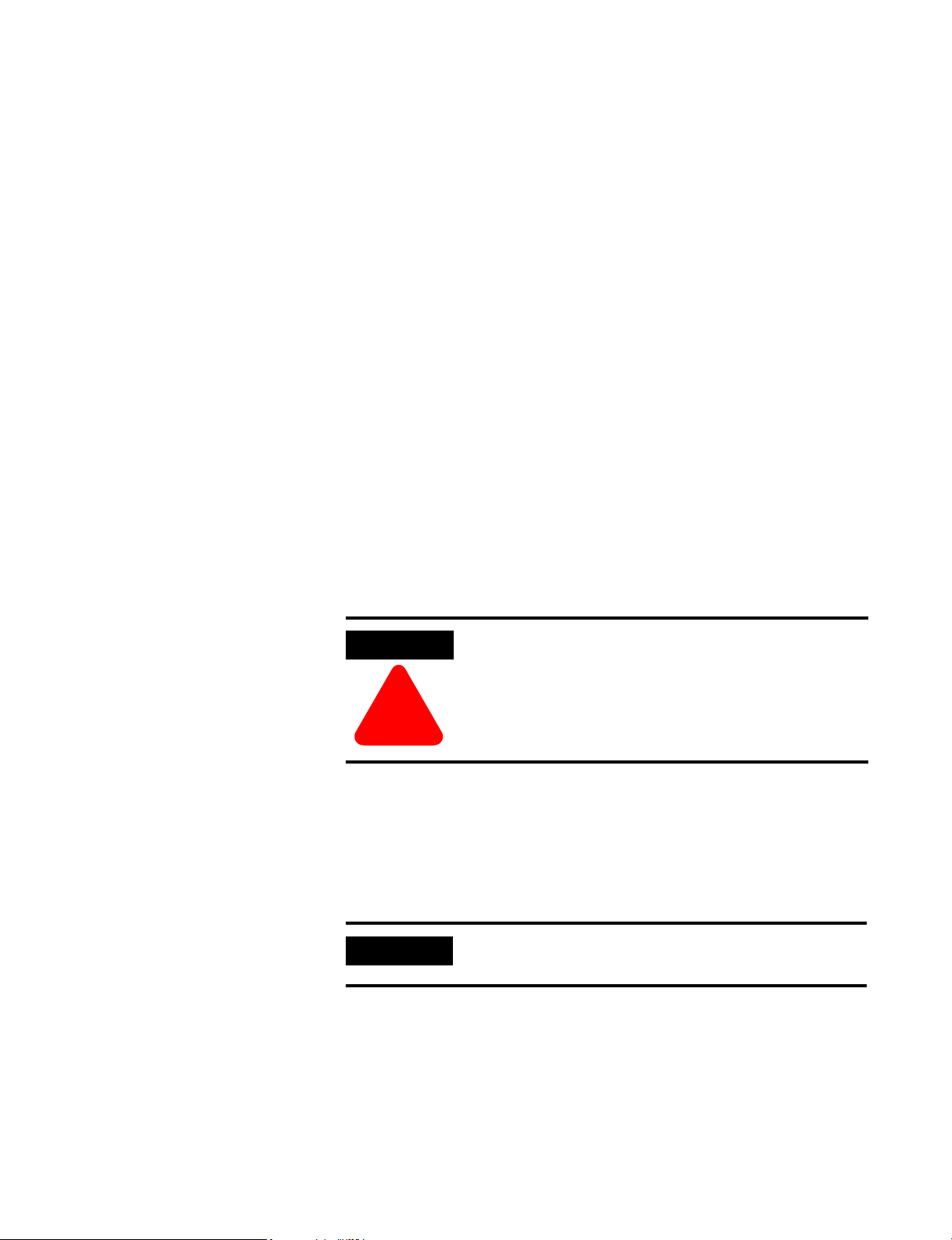
Figure 1.1 SoftLogix System with 1784-PM02AE
Components of the SoftLogix Motion System
Publication 1784-UM003A-EN-P – June 2003
Figure 1.2 SoftLogix System with 1784-PM16SE
Page 15
The SoftLogix Motion Control System 7
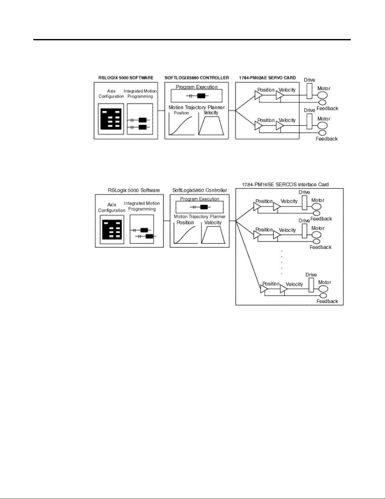
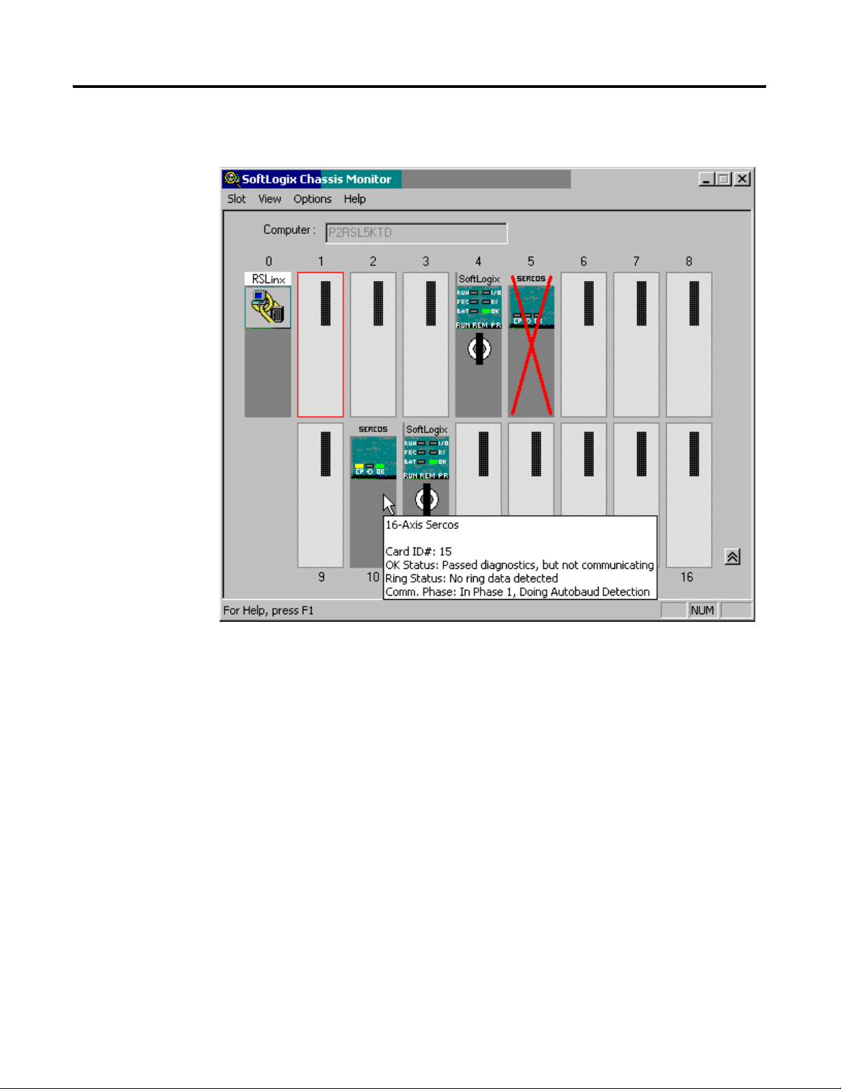
SoftLogix Chassis Monitor
It is at the Chassis Monitor where you can change the processor mode, and
view system status. After you have created and configured the various modules
of your SoftLogix system you can use the Chassis Monitor to display the
virtual chassis where you can monitor the simulated LEDs to view status
information for your modules.
Figure 1.3 SoftLogix Chassis Monitor
Publication 1784-UM003A-EN-P – June 2003
Page 16
8 The SoftLogix Motion Control System
Additional information in the form of a tooltip about the modules can be
ascertained by placing the mouse over a specific module.
The SoftLogix Controller
Figure 1.4 Additional Information for the PM16SE Card
The SoftLogix controller is the main component in the SoftLogix system. It
supports sequential and motion functions, and it performs all of the motion
command execution and motion trajectory planner functions. You can use one
or more SoftLogix controllers in each chassis, and each controller can control
up to 32 axes of motion.
The SoftLogix controller provides the following motion support:
• A high-speed motion task, which manages motion functions and
generates move profiles
• The ability to control up to 16 Analog/Encoder servo modules for a
total of 32 axes
• SERCOS support
Publication 1784-UM003A-EN-P – June 2003
Page 17

The SoftLogix Motion Control System 9
The Analog/Encoder Servo Module
(1784-PMO2AE)
The 16 Axis SERCOS interface
Module (1784-PM16SE)
The Analog/Encoder servo module provides an analog/quadrature encoder
servo drive interface. The servo module receives configuration and move
information from the SoftLogix controller and manages motor position and
velocity.
The servo module supports:
• Connection capability for up to two drives
• ±10V analog outputs
• Quadrature encoder inputs
• Home limit switch inputs
• Drive fault inputs
• Drive enable outputs
• 5V or 24V position registration inputs
• 250 μs position and velocity loop updates
The 16 Axis SERCOS interface modules (1784-PM16SE) serves as a link
between the SoftLogix platform and intelligent drives. The communication
link between the module and the drive(s) is via IEC 1491 SErial Real-time
COmmunication System (SERCOS) using fiber optic medium.
RSLogix 5000 Programming Software
The SERCOS interface module supports:
• reliable high speed data transmission
• excellent noise immunity
• elimination of interconnect wiring
• ASA messages converted to SERCOS formatted messages
The RSLogix 5000 programming software provides complete programming
and commissioning support for the SoftLogix system. RSLogix 5000 is the
only programming software needed to fully configure and program SoftLogix
motion control systems.
RSLogix 5000 software provides the following motion support:
• Wizards for servo axis configuration including drive hookup diagnostics
and auto tuning
• Ladder-based application programming including support for 31
motion commands
Publication 1784-UM003A-EN-P – June 2003
Page 18
10 The SoftLogix Motion Control System
Developing a Motion Control Application Program
Application Program Development
This section provides an introduction to concepts used in developing
application programs for motion control. These concepts include:
• Application program development
• The MOTION_INSTRUCTION tag
• Motion status and configuration parameters
• Modifying motion configuration parameters
• Handling motion faults
Developing a motion control application program involves the following:
Task Description
Select the master coordinated system
time
Name and Configure an axis Adds an axis to your application
Develop a motion application program Create a program for your motion
Add a motion module Adds a motion module to your
Assign additional servo modules and
axes
Run hookup diagnostics and auto
tuning
Sets one controller as the master
controller. Once you complete this
step, you can synchronize all the
motion modules and SoftLogix
controllers in your chassis
program
control application
application program
Adds additional modules and axes to
your application program
Completes hookup diagnostics and
auto tuning for each axis
The MOTION_INSTRUCTION Tag
Publication 1784-UM003A-EN-P – June 2003
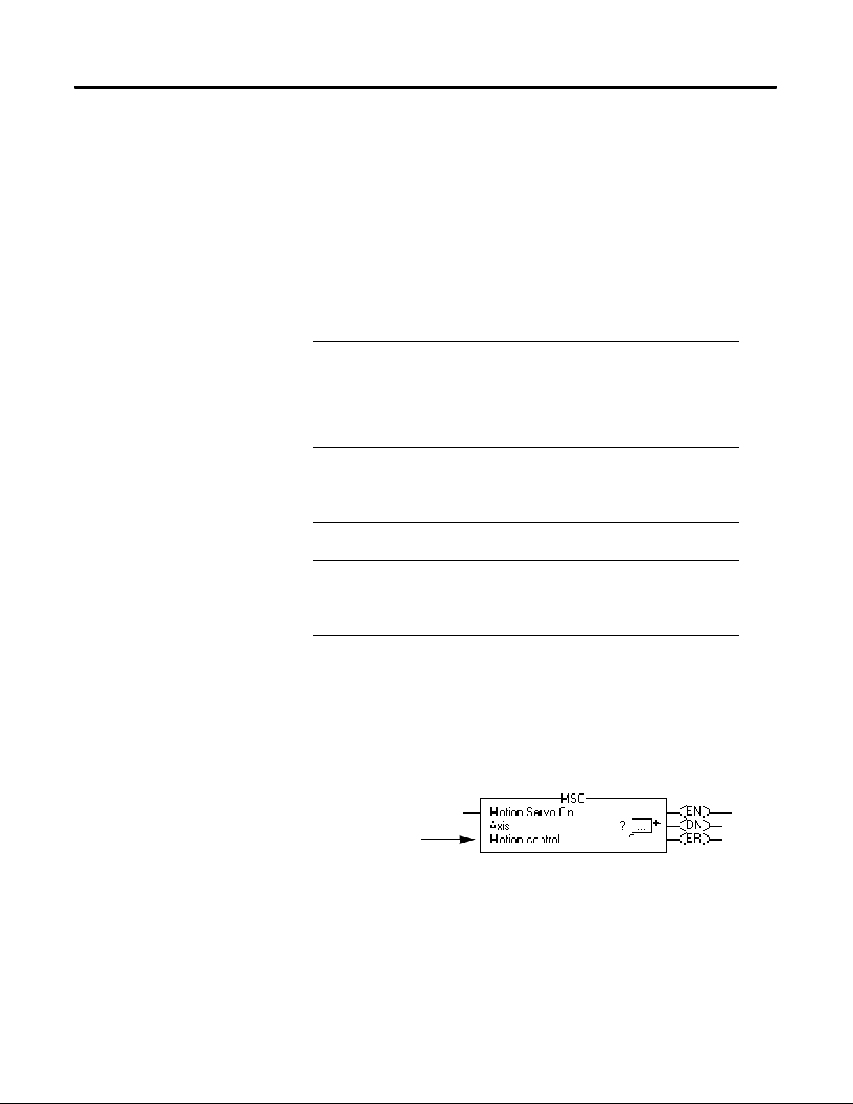
The controller uses the MOTION_INSTRUCTION tag (structure) to store
status information during the execution of motion instructions. Every motion
instruction has a motion control parameter that requires a
MOTION_INSTRUCTION tag to store status information.
The
motion control
parameter
Figure 1.5 Motion Control Parameter
Page 19
The SoftLogix Motion Control System 11
Motion Status and Configuration
Parameters
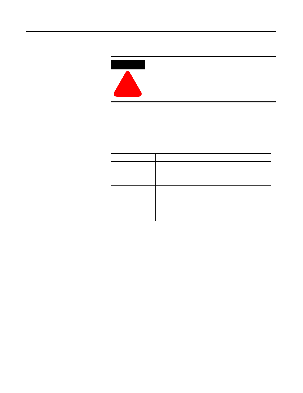
ATTENTION
Tags used for the motion control parameter of instructions
should only be used once. Re-use of the motion control
parameter in other instructions can cause unintended
operation of the control variables.
!
For more information about the MOTION_INSTRUCTION tag, refer to the
Logix5000 Controller Motion Instruction Set Reference Manual (1756-RM007).
You can read motion status and configuration parameters in your ladder logic
program using two methods.
Method Example For more information
Directly accessing
the AXIS and
MOTION_GROUP
structures
Using the GSV
instruction
• Axis faults
• Motion status
• Servo status
• Actual
position
• Command
position
• Actual
velocity
Refer to
Motion Instruction Set Reference
Manual (1756-RM007).
Refer to the Input/Output
Instructions chapter of the Logix
Controller Instruction Set Reference
Manual, publication 1756-RM003.
the Logix5000 Controller
Modifying Motion Configuration
Parameters
In your ladder logic program, you can modify motion configuration
parameters using the SSV instruction. For example, you can change position
loop gain, velocity loop gain, and current limits within your program.
For more information about the SSV instruction, refer to the Logix Controller
Instruction Set Reference Manual, publication 1756-RM003.
Publication 1784-UM003A-EN-P – June 2003
Page 20
12 The SoftLogix Motion Control System
Handling Motion Faults
Two types of motion faults exist.
Type Description Example
Motion
Instruction
Errors
Minor/Maj or Faults
• Do not impact controller
operation
• Should be corrected to
optimize execution time and
ensure program accuracy
• Caused by a problem with
the servo loop
• Can shutdown the controller
if you do not correct the fault
condition
A Motion Axis Move (MAM)
instruction with a parameter out
of range
The application exceeded the
PositionErrorTolerance value
Errors
Executing a motion instruction within an application program can generate
errors. The MOTION_INSTRUCTION tag has a field that contains the error
code. For more information on error codes for individual instructions, refer to
the motion instruction chapters in the Logix5550 Controller Instruction Set
Reference Manual.
Minor/Major Faults
Several faults can occur that are not caused by motion instructions. For
example, a loss of encoder feedback or actual position exceeding an overtravel
limit cause faults. The motion faults are considered Type 11 faults with error
codes from 1 to 32. For more information about motion error codes, refer to
Handling Controller Faults in the Logix Controller User Manual.
TIP
You can configure a fault as either minor (non major) or
major by using the Axis Wizard-Group window.
For more information about handling faults, see Handling Controller Faults in the
Logix 5000 Controller User Manual.
Publication 1784-UM003A-EN-P – June 2003
Page 21

SoftLogix Controller
Chapter
2
Introduction
Before you can begin programming or configuring your controller, you must
create a project file in which to store it.
To create a Project:
1. From the Type pull-down menu, choose the controller type that you
wish to use for this project.
2. Enter the name you wish to use for the controller.
The same name is used for the project file with the .acd extension.
3. Enter a description of the controller.
4. Choose the appropriate chassis type in which the controller resides.
5. Enter the slot number for the controller.
In SoftLogix, controllers occupy a numbered slot in the chassis and can be
placed in any slot. It is also possible to place multiple controllers in the same
chassis.
6. Verify the appropriate revision information for your controller. This
field defaults to the latest revision for the given controller type.
7. Enter the directory in which you want to store the project file.
The directory defaults to the one you configured in the Workstation Options
dialog. If you want to use a different directory, type its path or click on the
Browse button to find the directory.
The project file is created in this directory with the same name as the
controller with a .ACD file extension. For example, if your controller name is
Oven1, the project file name becomes Oven1.ACD.
8. Click on OK to create the project.
Once the project file is created, you can see the Controller Organizer, which
shows everything in the controller. The default configuration contains a
continuous task, called Main Task. The Main Task contains a program called
Main Program. The Main Program contains a routine called Main Routine,
which is configured as the main routinedef_main_routine@gloss.hlp.
13 Publication 1784-UM003A-EN-P – June 2003
Page 22
14 SoftLogix Controller
In addition, if you have chosen a FlexLogix controller, 2 FlexBus adapters are
created in slots 3 and 4 under the I/O Configuration folder. These 2 folders
contain all local I/O for FlexLogix, other than the 2 local slots for
communication. The first folder contains all I/O configured on the local Flex
rail housing the Flex controller; the second folder contains all I/O configured
for the local non-controller rail.
Note: You cannot delete, copy, cut, paste, or drag and drop the FlexBus
adapters. Once you create a FlexLogix controller, the adapters appear
under the I/O Configuration folder and cannot be altered unless you
delete the FlexLogix controller.
Accessing the New Controller Dialog
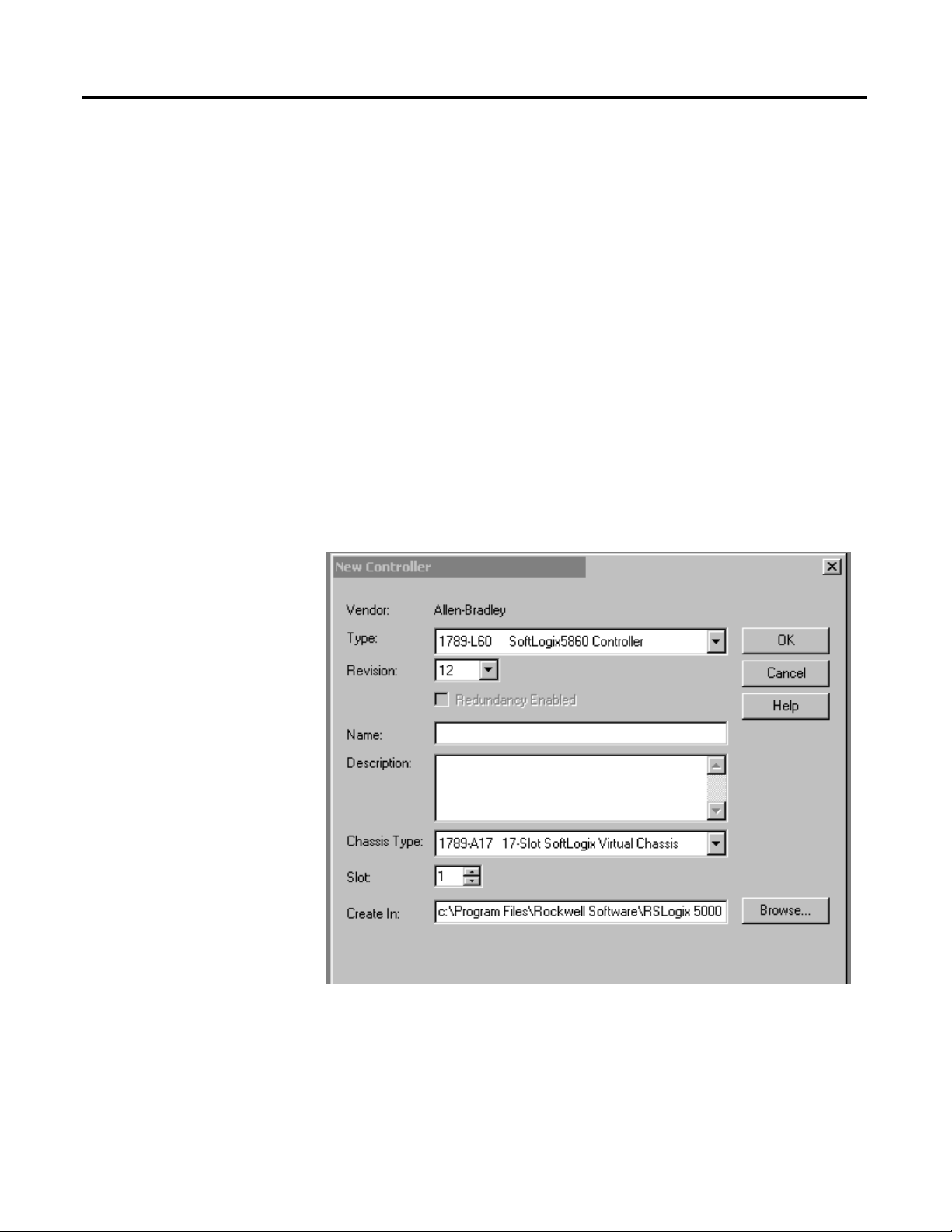
New Controller Dialog
From the File menu, choose New to access the New Controller dialog.
Create a new controller (i.e., project) from this dialog.
Publication 1784-UM003A-EN-P – June 2003
Figure 2.1 New Controller Dialog
Page 23

SoftLogix Controller 15
Vendor
Displays the name of the controller’s manufacturer.
Ty pe
Select the controller type from the pull-down menu, shown here by catalog
number, platform, and processor.
Choose from:
• 1756-L1 ControlLogix5550 Controller
• 1756-L55 ControlLogix5555 Controller
• 1756-L61 ControlLogix5561 Controller
• 1756-L62 ControlLogix5562 Controller
• 1756-L63 ControlLogix5563 Controller
• 1756-LCE ControlLogixCE Controller
• 1769-L20 CompactLogix5320 Controller
• 1769-L30 CompactLogix5330 Controller
• 1769-L35E CompactLogix5335E Controller
• 1789-L60 SoftLogix5860 Controller
• 1794-L33 FlexLogix5433 Controller
• 1794-L34 FlexLogix5434 Controller
• 618x-LCE PanelViewLogix Controller
• Emulator RSLogix Emulate 5000 Controller
• PowerFlex700S DriveLogix5720 Controller
Redundancy Enabled
Check this box if you wish to enable redundancy for this controller. Note that
this option is disabled if you have chosen a controller that does not support
redundancy.
Name
Enter the name you wish to use for the new controller. This name is also used
for the project file, with a .acd extension.
Description
Enter a description of the controller.
Publication 1784-UM003A-EN-P – June 2003
Page 24

16 SoftLogix Controller
Chassis Type
Select the appropriate chassis type from the pull-down menu, shown here by
catalog number. The software uses this information to determine the number
of slots in the chassis. Depending on the controller type you chose, the
available options in this menu vary:
For this platform: Choose from these chassis types:
ControlLogix 1756-A4, 4-slot ControlLogix chassis
1756-A7, 7-slot ControlLogix chassis
1756-A10, 10-slot ControlLogix chassis
1756-A13, 13-slot ControlLogix chassis
1756-A17, 17-slot ControlLogix chassis
CompactLogix Not applicable
SoftLogix 1789-17, 17-slot SoftLogix virtual chassis
FlexLogix Not applicable
DriveLogix Not applicable
Slot Number
Choose the slot number where the controller resides on the backplane.
For ControlLogix controllers, the default value is 0. If the slot number exceeds
the chassis size, an error message appears, prompting you to enter a number
within the valid range.
For SoftLogix controllers, the default value is 1.
For CompactLogix, FlexLogix, and DriveLogix controllers, the value in this
field is always 0 and cannot be edited.
Revision
Enter the controller revision.
For this release of RSLogix 5000, this field is not editable. The revision
defaults to the latest revision for the given controller type.
Create In:
Publication 1784-UM003A-EN-P – June 2003
Enter the directory in which you want the project file to be created. The file
name is the same as the controller name, with a .acd extension.
Browse
Click on this button to bring up the Choose Directory dialog from which you
can browse for the appropriate directory.
Page 25
SoftLogix Controller 17
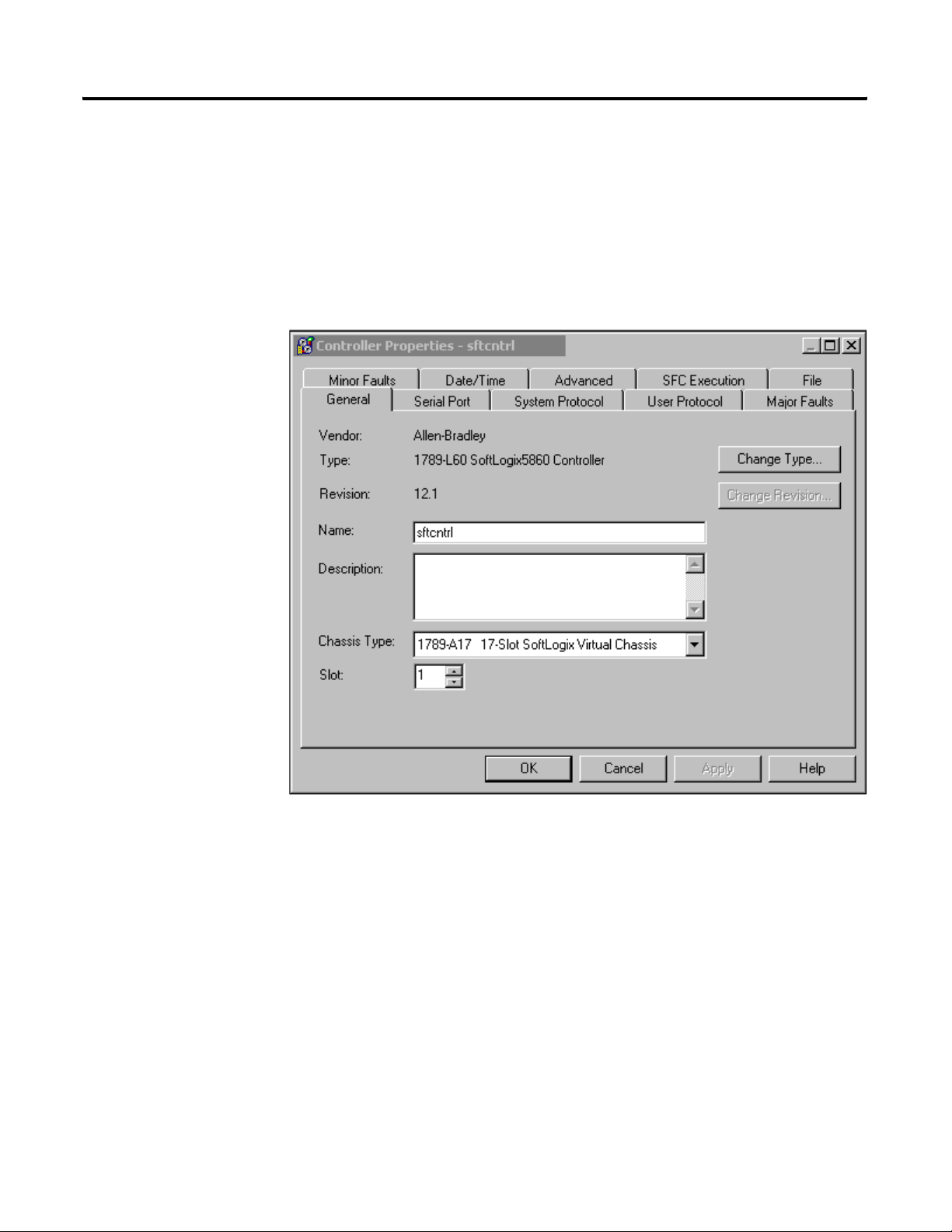
Editing Controller Properties
The Controller Properties dialog displays controller configuration information
for the open project and, when online, for the attached controller. The Tabs
that appear are governed by the type of the selected controller. This section
describes the fields on each of the dialogs for the Controller Properties.
General Tab
The General tab displays the controller name and description, as well as the
physical properties of the controller.
Figure 2.2 Controller Properties General Tab
Vendor
Displays the name of the controller’s manufacturer.
Ty pe
The catalog number and description of the controller. When online, this field
includes the catalog number of the memory card (if any).
Publication 1784-UM003A-EN-P – June 2003
Page 26

18 SoftLogix Controller
Name
The name of the controller. When you create a project, this is the same as the
name of the project file. When you change the name of the controller,
however, the name of the project file does not change. If you want to keep the
two the same, then you must rename the file using Windows Explorer or a
similar file management tool.
IMPORTANT
You cannot change the name when online.
This name must be IEC_1131 compliant. If you enter an
invalid character in this field, or if the name you enter
exceeds 40 characters, the software ignores the character.
Description
Enter a description for the controller here, up to 128 characters. You can use
any printable character in this field. If you exceed the maximum length, the
software ignores any extra characters.
Chassis Type
Select a supported chassis type from the pull-down list. Each entry in the list
consists of the catalog number of the chassis, as well as a brief description.
The chassis type cannot be changed when online.
Slot
Publication 1784-UM003A-EN-P – June 2003
Enter the chassis slot number in which the controller resides. The spin button
contains values that range from 0 to 1 less than the chassis size (e.g., if you
have a 4-slot chassis, the spin button spins from 0 to 3). If you enter a slot
number that is out of this range, you receive an error message when you go to
apply your changes.
The slot number cannot be changed when online.
Revision
Displays the major and minor firmware revision of the controller. The minor
revision is available only when you are online.
Change Type
Click on this button to access the Change Processor Type dialog. This dialog
lets you change your controller to another controller within the same platform.
Page 27
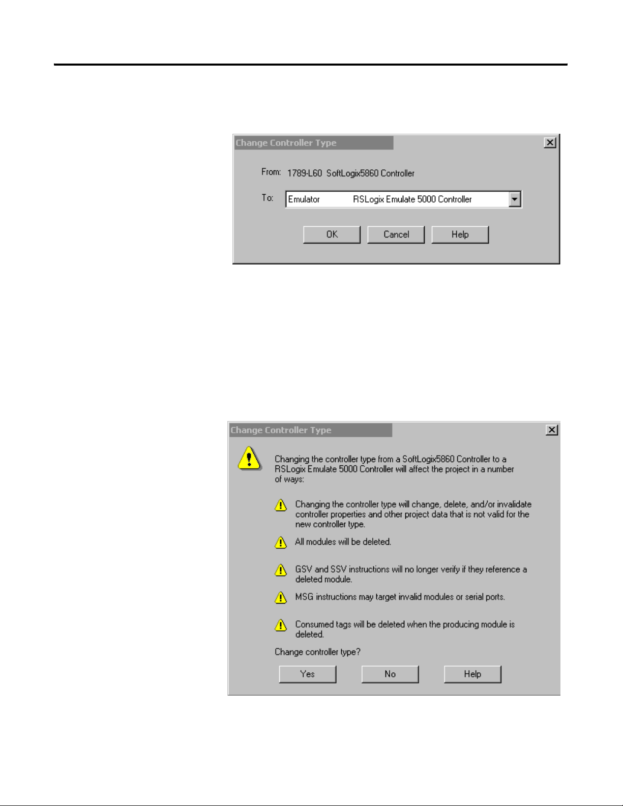
SoftLogix Controller 19
Change Controller Type Dialog Box
Overview
Use this dialog to change your controller to another controller within the same
platform (e.g. changing from a 1756-L1 ControlLogix 5550 Controller to a
1756-L53/A ControlLogix 5553 controller).
Figure 2.3 Change Controller Type Dialog
Select a processor to change to
Choose the controller you wish to change to from the pull-down menu. The
list of available controllers includes all controller types except the current
processor itself. Once a new controller is selected and the OK button is
clicked, a warning message displays. There are two different warning screens
depending upon whether the change is within the same platform or to another
platform. These warnings inform you that certain settings and properties are
changed or deleted based upn the type of controller selected.
Figure 2.4 Warning Message for Change to a Different Platform
Publication 1784-UM003A-EN-P – June 2003
Page 28
20 SoftLogix Controller
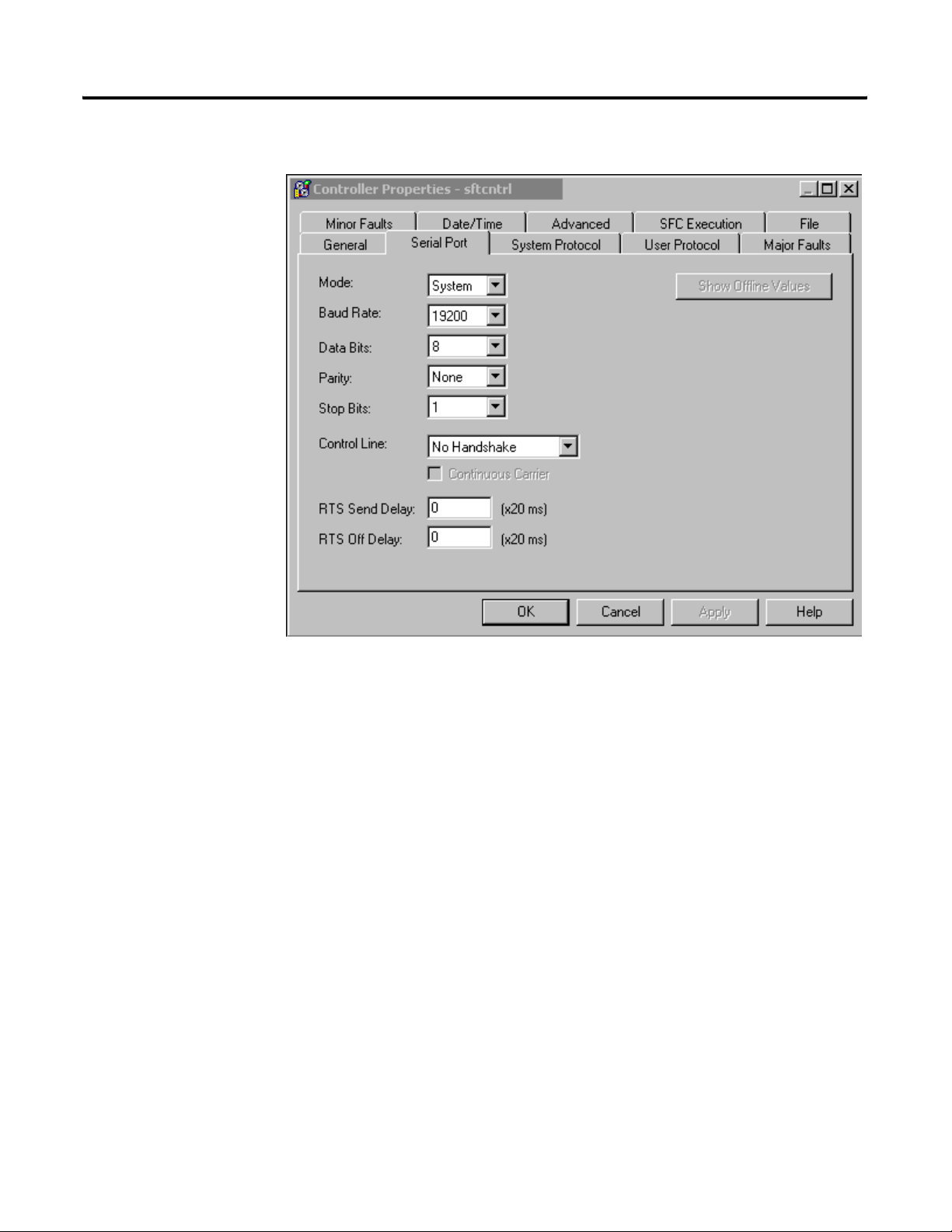
Serial Port Tab
The Serial Port tab allows you to view and configure the controller’s serial port.
Figure 2.5 Controller Properties Serial Port Tab
Mode
The type of protocol you want to use. Choose from System or User (default).
Baud Rate
The baud rate assigned to the serial port on the Logix5550. Choose from 110,
300, 600, 1200, 2400, 4800, 9600, 19200 (default), and 38,400.
Data Bits
The actual number of bits of data per character. Choose from 7 (ASCII only)
or 8 (default).
Parity
The parity for the link. Choose from Even, Odd (ASCII only) or No Parity
(default).
Publication 1784-UM003A-EN-P – June 2003
Page 29

SoftLogix Controller 21
Stop Bits
The actual number of stop bits per character. Choose from 2 (ASCII only) or 1
(default).
Control Line
Choose the type of handshaking you wish to use during communications. The
choices available to you vary, depending on the protocol you have selected:
For this mode: And this protocol: Choose from:
User ASCII No Handshake (default)
Full Duplex
Half Duplex
System Point-to-Point No Handshake (default)
Full Duplex
Slave No Handshake (default)
Half Duplex
Master No Handshake (default)
Full Duplex
Half Duplex
Continuous Carrier
Check this box if you wish to use Half Duplex communication with
continuous carrier. This checkbox is disabled if you have chosen something
other than Half Duplex communication, or if you have chosen Master as your
protocol. By default, this option is unchecked when enabled.
RTS Send Delay
Enter the time (in ms) to delay transmitting the first character of a message
after turning on the RTS line. The default value is 0.
RTS Off Delay
Enter the time (in ms) to delay turning off the RTS line after the last character
has been transmitted. The default value is 0.
Publication 1784-UM003A-EN-P – June 2003
Page 30
22 SoftLogix Controller
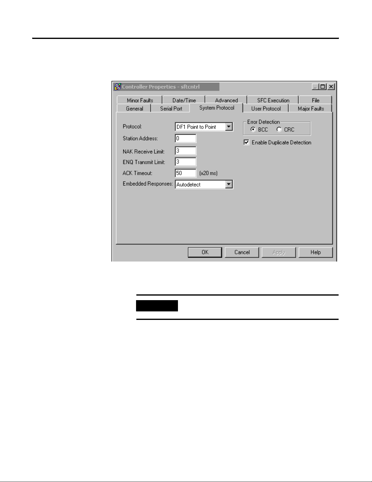
System Protocol Tab
The System Protocol tab allows you to configure the controller’s serial port for
DF1 Point to Point, DF1 Master, DF1 Slave or DH485. The parameters
present on this tab are dependent upon the protocol you select.
Figure 2.6 Controller Properties System Protocol Tab
IMPORTANT
If you wish to configure your system for ASCII, click on
the User Protocol tab.
The parameters present on this tab are dependent upon the protocol you
select.
Common Parameters
Protocol
Choose the protocol from the pull-down menu. Choose from DF1 Point to
Point (default), DF1 Slave, DF1 Master or DH485.
Station Address
Enter the current station link address of the com port to which the DF1 object
is now associated. Valid values are from 0 to 254; the default value is 0.
Publication 1784-UM003A-EN-P – June 2003
Page 31

SoftLogix Controller 23
Error Detection
Click on one of the radio buttons to specify the error detection scheme used
for all messages.
• BCC - the processor sends and accepts messages that end with a BCC
byte.
• CRC - the processor sends and accepts messages with a 2-byte CRC.
Enable Duplicate Detection
Check this box to enable duplicate message detection, which causes the object
to ignore all duplicate messages. This option is disabled by default.
ACK Timeout
Enter the time the object waits for an acknowledgment to a message
transmission. Valid values are from 0 to 65535, in 20 ms increments; the
default value is 50 ms.
DF1 Point to Point Parameters
ENQ Transmit Limit
Enter the number of inquiries you want the processor to send after an ACK
Timeout. Valid values are from 0 to 255; the default value is 3.
NAK Receive Limit
Enter the number of NAKs the processor can receive in response to a
message before stopping the transmission. Valid values are from 0 to 255; the
default value is 3.
Embedded Responses
This parameter sets the flag that enables the embedded response functionality.
Your options are:
• Autodetect – embedded responses are initiated only after one is
received.
• Enabled – embedded responses are enabled unconditionally.
Publication 1784-UM003A-EN-P – June 2003
Page 32

24 SoftLogix Controller
DF1 Slave Parameters
Transmit Retries
Enter the number of attempted transmits without getting an acknowledgment
before a message is deemed undeliverable. Valid values are from 0 to 255; the
default value is 3.
Slave Poll Timeout
Enter the amount of time that the master waits for an acknowledgment to a
message sent to the slave.
EOT Suppression
Check this box if you want to suppress "End of Text" transmissions at the end
of a slave message.
DF1 Master Parameters
Transmit Retries
Enter the number of attempted transmits without getting an acknowledgment
before a message is deemed undeliverable. Valid values are from 0 to 255; the
default value is 3.
Reply Message Wait
Enter the time (in ms) that the master waits after receiving an acknowledgment
to a master-initiated message before polling the slave for a reply. Specify this
time in 20 ms increments; the default value is 50 (i.e., 50*20 ms, or 1000 ms, or
1 second).
Polling Mode
Choose a polling mode from the pull-down menu. Choose from:
• Message Based - slave can initiate messages.
• Message Based - slave cannot initiate messages.
• Standard - Multiple message transfers per node scan.
Publication 1784-UM003A-EN-P – June 2003
• Standard - Single message transfer per node scan.
The default mode is Message Based, allowing a slave to initiate messages.
Page 33

SoftLogix Controller 25
Master Transmit
Choose the master message transmit that designates when to send any DF1
master message. Choose from:
• Between Station Polls - The master transmits a message before the next
station.
• In Poll Sequence - The master transmits messages only when the station
number is encountered in the poll list.
The default is Between Station Polls.
Normal Poll Node Tag
Choose the tag name of the structure that contains the normal poll node list.
Use the Tag Browser to select the appropriate tag name.
The default tag is <none>.
Normal Poll Group Size
Enter the total number of active stations polled from the poll node list. Valid
values are 0 to 255; the default value is 0.
Priority Poll Node Tag
Choose the tag name of the structure to store the priority poll node list. Use
the Tag Browser to select the appropriate tag name.
The default tag is <none>.
Active Station Tag
Choose the tag name of the structure to store the status (active/non-active) of
each node. Use the Tag Browser to select the appropriate tag name.
The default tag is <none>.
DH485 Parameters
Max Station Address
This field is available when you choose DH485 as the protocol. It sets the
maximum value allowable for the Station Address. The range is from 0 to 31.
Publication 1784-UM003A-EN-P – June 2003
Page 34

26 SoftLogix Controller
Token Hold Factor
A value between 1 and 4.
User Protocol Tab
The User Protocol tab allows you to configure the controller’s serial port for
the ASCII protocol.
Publication 1784-UM003A-EN-P – June 2003
Figure 2.7 Controller Properties User Protocol
Protocol
Choose the ASCII protocol.
Buffer Size
Enter the maximum size (in bytes) of the data array that you are planning on
sending and receiving. Valid values are from 1 to 65536; the default size is 82.
When the controller sends out the data, if it detects an array that is larger than
this buffer size, a minor fault occurs and the extra data is truncated. When the
controller receives data, if it detects data that is larger than the size of the
buffer, the extra characters are dropped.
Page 35

SoftLogix Controller 27
Termination Character 1 and 2
Enter the characters that be used to define the end of a line. Valid hex range
values are from 0 to 255. The default value for Termination Character 1 is $0D,
and the default value for Termination Character 2 is $FF.
The ARL and ABL instructions use these characters to signal the end of a line.
If you do not wish to use these characters, you can either avoid the use of these
instructions, or you can define Termination Character 1 as $FF, where $FF
tells the controller not to use any definable termination characters when using
the ARL or ABL instructions.
If you want to use only one character to signal the end of a line, use
Termination Character 1, and define Termination Character 2 as $FF.
Append Character 1 and 2
Enter the characters that are appended to the end of a line. Valid hex range
values are from 0 to 255. The default value for Append Character 1 is $0D, and
the default value for Append Character 2 is $0A.
The AWA instruction appends the specified characters to the end of the
messages it sends out. If you do not wish to use these characters, you can
either avoid the use of the AWA instruction, or you can define Append
Character 1 as $FF, where $FF tells the controller not to append characters
when using the AWA instruction.
If you want to append only one character, define Termination Character 1 as
the desired character, and define Termination Character 2 as 0xFF.
XON/OFF
Check this option to regulate the flow of incoming data.
For example, when this option is checked and the receive buffer gets to be
80% full, an XOFF (0x13) character is transmitted to tell the sending device to
stop sending. When the buffer has been processed so that it is less than 80%
full, the XON (0x11) character is sent to tell the device to resume sending.
This option is disabled when the Control Line option is configured for Half
Duplex.
Echo Mode
Check this option to cause any data received in the ASCII port to be sent right
back out to the device that sent it. For example, you could use this option with
a dumb terminal that is unable to display what it sends, but can display what is
echoed to it.
Publication 1784-UM003A-EN-P – June 2003
Page 36

28 SoftLogix Controller
This option is disabled when the Control Line option is configured for Half
Duplex.
Delete Mode
The character received just before the delete character sequence (0x7F) is
removed by the serial port driver before it is given to the ladder logic. Choose
from:
• Ignore - The delete character sequence is treated the same as any other
character that is read in.
• CRT or Printer - The preceding character in the string buffer is removed
before being given to the ladder logic. The only difference between CRT
and Printer modes is the type of device sending the string to the
controller. If Echo mode is disabled, CRT and Printer do exactly the
same thing.
Major Faults Tab
The Major Faults tab displays information on the major faults that have
occurred in the controller.
Publication 1784-UM003A-EN-P – June 2003
Figure 2.8 Controller Properties Major Faults Tab
Page 37

SoftLogix Controller 29
Number of Major Faults Since Last Cleared
Displays the number of major fault events that have been reported since the
log was last cleared.
Recent Faults
Displays a description of the last three major faults that have occurred. These
faults are stored in reverse chronological order. When offline, this field
contains the stored contents of the last online session.
Clear Majors
Click on this button to clear the Major Fault log.
Minor Faults Tab
The Minor Faults tab displays information on the minor faults that have
occurred in the controller.
Figure 2.9 Controller Properties Minor Fault Tab
Number of Minor Faults Since Last Cleared
Displays the number of minor fault events that have been reported since the
log was last cleared.
Publication 1784-UM003A-EN-P – June 2003
Page 38

30 SoftLogix Controller
Recent Faults
Displays a description of the last eight minor faults that have occurred. These
faults are stored in reverse chronological order. When offline, this field
contains the stored contents of the last online session.
Clear Minors
Click on this button to clear the Minor Fault log.
Fault Bits
Lists the minor fault bits that have a specific fault type assigned to them. If the
bit is set, the checkbox is set.
When offline, these checkboxes are disabled, but display the contents of the
last online session.
Date/Time Tab
The Date/Time tab allows you to view and edit the controller’s wall clock time
and the coordinated system time status.
Publication 1784-UM003A-EN-P – June 2003
Figure 2.10 Controller Properties Date/Time Tab
Page 39

SoftLogix Controller 31
Date
The wall clock date, in the format currently selected in the Regional Settings
application in your Windows NT Control Panel.
This parameter is read-only. When offline, this parameter is empty.
Time
The wall clock time, in the format currently selected in the Regional Settings
application in your Windows NT Control Panel.
This parameter is read-only. When offline, this parameter is empty.
Set
Click on this button to bring up the Set Date/Time dialog, from which you
can set the date and/or time.
This button is disabled when offline.
Make this controller the Coordinated System Time master
Click on this checkbox to select this controller as the CST master. This does
not mean that this controller IS the master, it means that you intend for this
controller to be the master. If another controller is already the CST master,
“duplicate master detected” appears in the status field.
If you are using a Servo card on this controller, set the CST Master.
Status
Indicates the state of the coordinated system time. There are four status fields,
with a circular indicator to the left of each. This indicator is blue if the
corresponding status condition is true; otherwise, it is clear. The status
conditions are:
• Is the master - you checked the “Make this controller the master” box,
and this controller is the CST master.
• Synchronized with a master - this controller is not the master; its time is
being synchronized by a master.
• Duplicate master detected - you checked the “Make this controller the
master” box, but there is already a CST master.
• Timer hardware faulted - there is a hardware fault.
Publication 1784-UM003A-EN-P – June 2003
Page 40

32 SoftLogix Controller
All of the circular indicators are clear when you are offline.
Advanced Tab
The Advanced tab allows you to view and edit advanced controller properties.
Figure 2.11 Controller Properties Advanced Tab
Memory Used
The amount of memory used in the controller. When offline, this parameter is
empty.
Memory Unused
The amount of memory available in the controller. When offline, this
parameter is empty.
Memory Total
The total amount of memory in the controller (used plus unused). If a memory
daughter card is present, this total includes that memory. When offline, this
parameter is empty.
Publication 1784-UM003A-EN-P – June 2003
Page 41

SoftLogix Controller 33
Controller Fault Handler
Choose the program that runs as the result of a system fault from the
pull-down menu. The list contains all of the unscheduled programs.
Power-Up Handler
Choose the program the processor executes when it powers up in Run mode
after a power-down in Run mode. The list contains all of the unscheduled
programs.
System Overhead Time Slice
Enter or select the percentage of time the controller spends running its system
task, relative to running user tasks.
SFC Execution Tab
The SFC Execution tab sets the configuration that affects the execution of the
SFC (Sequential Function Chart). These settings apply to the entire Controller
and therefore affect all SFCs within the Controller.
Figure 2.12 Controller Properties SFC Execution Tab
Publication 1784-UM003A-EN-P – June 2003
Page 42

34 SoftLogix Controller
Execution Control
This determines the execution model for the SFC. Your options are:
• Execute current active steps only – Execution control is returned to
the controller after processing the active steps, even if the Transitions
following the active steps are True.
• Execute until False transition – The controller continually processes
Steps and Transitions, in a single scan, until a False Transition is found.
It then returns to the Controller operating system.
Restart Position
Your selection here indicates at what point the SFC starts after it has
completed executing and been restarted.
• Restart at most recently executed step – Restarts at the step where it
left off.
• Restart at initial step – The SFC re-initializes and starts at the Initial
Step.
Last Scan of Active Steps
This determines how the controller performs a final scan of Action logic when
the associated Step is deactivated.
• Automatic reset – All non-retentive timers and outputs associated with
the Step’s non-stored Actions are reset when the step is deactivated.
• Programmatic reset – All non-retentive timers and outputs associated
with the Step’s non-stored Actions must be reset manually.
• Don’t scan – No scan is done on the Action logic when the associated
Step is deactivated.
Publication 1784-UM003A-EN-P – June 2003
Page 43

SoftLogix Controller 35
File Tab
The File tab displays information about the project file.
The fields on this tab cannot be edited. To change the file name or path, you
must use the Save As command.
Figure 2.13 Controller Properties File Tab
Name
The name of the project file
Path
The drive and directory of the project file.
Created
The creation date and time of the project file, in the format currently selected
in the Regional Settings application in your Windows NT Control Panel.
Edited
The date and time that the project file was last edited, in the format currently
selected in the Regional Settings application in your Windows NT Control
Panel.
Publication 1784-UM003A-EN-P – June 2003
Page 44

36 SoftLogix Controller
Redundancy Tab
The Redundancy Tab is only present if the specified processor type and
version supports the Redundancy feature. This tab supports the configuration
for redundancy.
Figure 2.14 Controller Properties Redundancy Tab
Redundancy Enabled
This checkbox lets you select whether to enable the redundancy feature or not.
It can only be selected when the Controller is offline. When it is on-line it
provides a valid indication of the redundancy enabled selection.
Redundancy Status
This section shows the redundancy states.
Chassis ID – Displays the chassis identification.
Chassis State – This shows the redundancy state of the entire chassis. The
possible states include:
0 – Unsupported – also displays when the system is offline.
1 – Undetermined
2 – Primary with Synchronized Secondary
3 – Primary with Disqualified Secondary
Publication 1784-UM003A-EN-P – June 2003
Page 45

SoftLogix Controller 37
4 – Primary with no partner
8 – Synchronized Secondary
9 – Disqualified Secondary with partner
10 – Disqualified Secondary with no partner
Module State – Indicates the redundancy state of the controller. If the
controller does not have the redundancy feature or if it is offline, this field is
empty and the controls are disabled. The possible states include:
0 – Unsupported – also displays when the system is offline.
1 – Undetermined
2 – Primary with Synchronized Secondary
3 – Primary with Disqualified Secondary
4 – Primary with no partner
6 – Synchronizing Primary
7 – Synchronizing Secondary
8 – Synchronized Secondary
9 – Disqualified Secondary with partner
10 – Disqualified Secondary with no partner
Module Compatibility – Shows the modules compatibility with its
corresponding module in the partner chassis. If the controller does not have
the redundancy feature or if it is offline, this field is empty and the controls are
disabled. The possible states include:
0 – Unsupported – also displays when the system is offline.
1 – No compatible Partner
2 – Fully compatible Partner
Publication 1784-UM003A-EN-P – June 2003
Page 46

38 SoftLogix Controller
Partner Status
This section shows information on the status of the Partner module.
Mode – Shows the current state of the partner module’s mode. If the
controller does not have the redundancy feature or if it is offline, this field is
empty and the controls are disabled. Valid modes include:
• Faulted
• Run
• Program
• Test
• Unknown – Displayed for any mode that is not one of those listed
above. It also displays if the Module Compatibility is not "Fully
Compatible Partner" or "Standby Compatible Partner". Also displays
when the system is offline.
Key Switch Position – Shows the current status of the partner module’s
keyswitch position. If the controller does not have the redundancy feature or if
it is offline, this field is empty and the controls are disabled. Valid modes
include:
• Run
• Remote
• Program
• Unknown – Displays when the Module Compatibility is not "Fully
Compatible Partner" or "Standby Compatible Partner". Also displays
when the system is offline.
Publication 1784-UM003A-EN-P – June 2003
Key Switch Mismatch – Is activated when there is a mismatch between the
key switch position between the primary and partner modules.
Partner Minor Faults
This section shows the minor faults that are set in the partner controller. These
controls are read-only. If the controller does not have the redundancy feature
or if it is offline, the radio button is greyed and the text label is disabled. Minor
partner faults include:
• Powerup
• I/O
• Program
• Watchdog
• Serial Port
• Battery
Page 47

SoftLogix Controller 39
Advanced Button
The Advanced Button displays configuration parameters for retaining test
edits when switched to a secondary system and lets you set the percentage of
memory that is reserved for the data table.
Nonvolatile Memory Tab
Figure 2.15 Advanced Button from Redundancy Tab
Retain Test Edits on Switchover
Select the checkbox to allow temporary execution of online edits to be
maintained or canceled when a switchover to a secondary system occurs.
When enabled, this option prevents the Logix controller from automatically
switching back to the unedited version of your program if the primary chassis
fails while testing on-line edits.
Memory Usage
Lets you modify the percentage of memory that is to be reserved in the data
table area. This lets you create tags in RUN mode on a synchronized primary
system.
The Nonvolatile Memory tab of the Controller Properties dialog serves as the
starting point from which you can perform nonvolatile memory operations.
Publication 1784-UM003A-EN-P – June 2003
Page 48

40 SoftLogix Controller
Click on the Load/Store button to access the Nonvolatile Memory
Load/Store dialog, from which you can perform the actual operations.
The Nonvolatile Memory tab also provides you with status information that
indicates any conditions that might prevent you from loading or storing.
Possible status messages include:
• Nonvolatile memory not present.
• Nonvolatile memory not supported in redundant systems.
• Controller being edited by another user.
• No controller image or stored controller image.
• Controller not in Program mode.
• Stored image revision in nonvolatile memory does not match controller
revision.
The Controller Properties dialog displays controller configuration information
for the open project and, when online, for the attached controller.
The Nonvolatile Memory tab provides you with access to nonvolatile memory
operations.
Note: This tab is available only when the selected controller supports
nonvolatile memory.
Publication 1784-UM003A-EN-P – June 2003
Page 49

SoftLogix Controller 41
Figure 2.16 Controller Properties Nonvolatile Memory Tab
Name
The name of the stored controller image that resides in nonvolatile memory.
Ty pe
The controller type for the image stored in nonvolatile memory. This
controller type can be any type that supports nonvolatile memory.
Revision
The firmware revision of the controller when the image in nonvolatile memory
was stored. In order for the image in nonvolatile memory to be loaded back
into controller memory, the firmware revision of that image must match the
revision of the controller.
Publication 1784-UM003A-EN-P – June 2003
Page 50

42 SoftLogix Controller
Load Image
The condition under which the image stored in nonvolatile memory is loaded
back to controller memory. Available conditions include:
• On Corrupt Memory – this will cause a load whenever there is no
project in the controller and you turn on or cycle power on the chassis.
If you are using a battery the controller, selecting this option performs a
load only if the battery has failed to maintain the project during a loss of
power.
• On Power Up – this will cause a load whenever you turn on or cycle
power on the chassis. If you are using a battery on the controller,
selecting this option performs a load even if the battery has maintained
the project during loss of power.
• User Initiated – choose this option if you want to load only through
RSLogix 5000 software.
Regardless of the currently-selected load option, you can always manually
initiate a load as well.
Load Mode
The mode the controller enters upon loading from nonvolatile memory.
Choose from:
• Program (Remote Only)
• Run (Remote Only)
TIP
The Load Mode only applies if the Load Image selection is On Corrupt
Memory or On Power Up. If the Load Image is User Initiated, the Load Mode
is disabled.
The Load Mode only applies if the controller keyswitch is
in the remote position when loading. If the controller
keyswitch is in Run or Program the controller will be
returned to that mode once the load is complete. The
controller keyswitch always has priority over the Load
Mode.
Publication 1784-UM003A-EN-P – June 2003
Image Note
Descriptive information that you entered at the time the image was stored in
nonvolatile memory. You may enter up to 128 text characters.
Page 51

SoftLogix Controller 43
Stored
The workstation date and time when the image was stored in nonvolatile
memory.
Load/Store
Click on this button to access the Load/Store dialog.
This button is disabled when:
• Nonvolatile memory is not present in the controller.
• The controller is in Run mode.
• Another user has locked the controller.
• Redundancy is enabled for the controller.
• The controller is offline.
If the Load/Store button is disabled, the status bar indicates the reason. Note
that the status bar displays only one status at a time, and you must work
through each of them to enable the Load/Store button.
Publication 1784-UM003A-EN-P – June 2003
Page 52

44 SoftLogix Controller
Publication 1784-UM003A-EN-P – June 2003
Page 53

Chapter
3
Adding and Configuring Your 1784-PM02AE Motion Module
This chapter describes how to add, configure, and edit your 1784-PM02AE
motion module for use in your motion control application.
Adding the 1784-PM02AE Module
To use your motion module in a control system, you must add your motion
module to the application program. To add a motion module:
1. Right-click the I/O Configuration folder.
Figure 3.1 Selecting New Module from the Controller Organizer
45 Publication 1784-UM003A-EN-P – June 2003
Page 54

46 Adding and Configuring Your 1784-PM02AE Motion Module
2. Select New Module. The Select Module Type window appears.
Figure 3.2 Select Module Type Screen Fully Loaded
Publication 1784-UM003A-EN-P – June 2003
Page 55

Adding and Configuring Your 1784-PM02AE Motion Module 47
3. Click on the Clear All button to clear the dialog window then click on
Motion to list the available Motion Controllers.
New Module
Figure 3.3 Select Module Type Screen with Motion Options - M02AE Highlighted
Use this dialog to select and create a new module. Highlight the
1784-PM02AE The context sensitive menu appears, from which you can select
a New Module.
Ty pe
The Type field displays the catalog number of the module highlighted in the
Type list box. You can either type in a module catalog number in this field to
quickly select/find the module you want to create or you can scroll through
the list of modules in the Type list box.
Publication 1784-UM003A-EN-P – June 2003
Page 56

48 Adding and Configuring Your 1784-PM02AE Motion Module
Major Revision
Select the major revision number of the physical module that you want in the
chassis.
The major revision is used to indicate the revision of the interface to the
module.
Type (list box)
This box lists the installed module catalog numbers based on the selected
check boxes.
Description (list box)
This portion of the list box contains descriptions of the modules.
Show
Displays check boxes, which support filtering on particular types of modules.
Check this box: If you want to:
Digital display digital modules supported by the software
Analog display analog modules supported by the software
Communication display communication modules supported by the software
Motion display motion modules supported by the software
Controller display controller modules supported by the software
Vendor display a particular vendor's module profiles that are installed on the system.
Other display modules that do not fit under the rest of the check box categories.
Select All
Click on this button to display all modules in the list box; all the check boxes in
the Show field are checked.
Clear All
Publication 1784-UM003A-EN-P – June 2003
Click on this button to clear all check boxes in the Show field.
4. In the Type field, select 1784-PM02AE 2 Axis Analog/Encoder Servo.
Page 57

Adding and Configuring Your 1784-PM02AE Motion Module 49
5. Select OK. The Module Create Wizard displays.
Figure 3.4 Module Properties Dialog Wizard - Naming the Module
6. Make entries in the following fields.
Field Entry
Name Type a name for the servo module.
The name can:
• have a maximum of 40 characters
• contain letters, numbers and underscores (_).
Slot Enter the number of the chassis slot that contains your
module.
Description Type a description for your motion module.
This field is optional.
Electronic
keying
Select the electronic keying level.
To Select
Match the vendor, catalog
number, and major revision
attributes of the physical module
and the software configured
module
Disable the electronic keying
protection mode
Match the vendor, catalog
number, major revision, and
minor revision attributes of the
physical module and the
software configured module
Compatible module
Disable keying
Exact match
Publication 1784-UM003A-EN-P – June 2003
Page 58

50 Adding and Configuring Your 1784-PM02AE Motion Module
7. Press the Next button to proceed to the next Create Wizard screen.
Figure 3.5 Module Properties Wizard - Fault Handling
8. This screen is where you determine how faults are to be handled. The
choices are to inhibit module or to configure the module so that a loss
of connection to this module causes a major fault. Make your entries
and press the Next button to proceed to the next wizard screen.
Publication 1784-UM003A-EN-P – June 2003
Figure 3.6 Module Properties Wizard - Servo Update/Associated Axis
Page 59

Adding and Configuring Your 1784-PM02AE Motion Module 51
9. This screen lets you associate an axis with the module. Make the
appropriate choices for your application. At this point, the rest of the
screens are informational only and it would be best to press the Finish
button to create the module.
All of the above screens can be accessed and edited by going to the tabbed
Module Property screens. Further explanations of the fields in this dialog are
detailed below.
Editing Your Motion Module Settings
The following section provides explanations of the Motion Module Properties
screens. Use these screens to edit the properties of the module when changes
need to be made. You can access the Module Properties screen by highlighting
the motion module and right clicking the mouse.
Select Properties from the displayed pop-up menu screen as shown in the
following figure.
Figure 3.7 Controller Organizer - Module Properties Pop up
Publication 1784-UM003A-EN-P – June 2003
Page 60

52 Adding and Configuring Your 1784-PM02AE Motion Module
This accesses the Module Properties screen. The screen is tabbed to expedite
movement to the required dialog.
General Tab
Figure 3.8 Module Properties - General Tab
Use this tab to create/view module properties for 1784-PM02AE motion
module. This dialog provides you with the means to view the type, description,
vendor, and the name of the parent module. You can also enter the name and a
description for the module. Other fields and buttons on this dialog let you set
the slot location of the module, review information for both channels, go to
the New Tag dialog to create an axis to associate with one of the channels,
select the minor revision number and select an electronic keying option. You
can also view the status the controller has about the module but, only when
online.
Ty pe
Displays the type and description of the module being created (read only).
Vendor
Displays the vendor of the module being created (read only).
Name
Publication 1784-UM003A-EN-P – June 2003
Enter the name of the module.
Page 61

Adding and Configuring Your 1784-PM02AE Motion Module 53
The name must be IEC 1131-3 compliant. If you attempt to enter an invalid
character or exceed the maximum length, the software beeps and ignores the
character.
Description
Enter a description for the module here, up to 128 characters. You can use any
printable character in this field. If you exceed the maximum length, the
software beeps to warn you, and ignores any extra characters.
Slot
Enter the slot number where the module resides. The spin button contains
values that range from 0 to 1 less than the chassis size (e.g., if you have a 4-slot
chassis, the spin button will spin from 0 to 3). If you enter a slot number that
is out of this range, you will receive an error message when you go to apply
your changes.
The slot number cannot be changed when online.
Revision
Select the minor revision number of your module.
The revision is divided into the major revision and minor revision. The major
revision displayed statically is chosen on the Select Module Type dialog.
Electronic Keying
Select one of these keying options for your module during initial module
configuration:
• Exact Match - all of the parameters must match or RSLogix rejects the
inserted module.
• Vendor
• Product Type
• Catalog Number
• Major Revision
• Minor Revision
• Compatible Module
• the Module Types, Catalog Number, and Major Revision must match
• the Minor Revision of the physical module must be equal to or
greater than the one specified in the software or RSLogix 5000 will
reject the inserted module.
• Disable Keying - RSLogix 5000 will not employ keying at all.
Publication 1784-UM003A-EN-P – June 2003
Page 62

54 Adding and Configuring Your 1784-PM02AE Motion Module
When you insert a module into a slot in a ControlLogix chassis, RSLogix 5000
compares the following information for the inserted module to that of the
configured slot:
• Vendor
• Product Type
• Catalog Number
• Major Revision
• Minor Revision
This feature prevents the inadvertent insertion of the wrong module in the
wrong slot.
Connection Tab
The Connection Tab is used to define controller to module behavior. This is
where you select a requested packet interval, choose to inhibit the module,
configure the controller so loss of the connection to this module causes a
major fault, and view module faults.
Publication 1784-UM003A-EN-P – June 2003
Figure 3.9 Module Properties - Connection Tab
The data on this tab comes directly from the controller. This tab displays
information about the condition of the connection between the module and
the controller.
Requested Packet Interval
This does not apply to motion modules.
Page 63

Adding and Configuring Your 1784-PM02AE Motion Module 55
Inhibit Module checkbox
Check/Uncheck this box to inhibit/uninhibit your connection to the module.
Inhibiting the module causes the connection to the module to be broken.
TIP
ATTENTION
Inhibiting/uninhibiting connections applies mainly to
direct connections, and not to the CNB module
Inhibiting the module causes the connection to the module
to be broken and may result in loss of data
!
When you check this box and go online, the icon representing this module in
the controller organizer displays the Attention Icon.
If you are: Check this checkbox to:
offline put a place holder for a module you are configuring
online stop communication to a module
If you inhibit the module while you are online and connected to the module, the
connection to the module is nicely closed. The module's outputs go to the last
configured Program mode state.
If you inhibit the module while online but a connection to the module has not
been established (perhaps due to an error condition or fault), the module is
inhibited. The module status information changes to indicate that the module
is 'Inhibited' and not 'Faulted'.
If you uninhibit a module (clear the checkbox) while online, and no fault
condition occurs, a connection is made to the module and the module is
dynamically reconfigured (if you are the owner controller) with the
configuration you have created for that module.
If you are a listener (have chosen a “Listen Only” Communications Format), you
can not re-configure the module.
If you uninhibit a module while online and a fault condition occurs, a
connection is not made to the module.
Major Fault on Controller if Connection Fails checkbox
Check this box to configure the controller so that failure of the connection to
this module causes a major fault on the controller if the connection for the
module fails.
Publication 1784-UM003A-EN-P – June 2003
Page 64

56 Adding and Configuring Your 1784-PM02AE Motion Module
Module Fault
Displays the fault code returned from the controller (related to the module you
are configuring) and the text detailing the Module Fault that has occurred.
The following are common categories for errors:
• Connection Request Error - The controller is attempting to make a
connection to the module and has received an error . The connection
was not made.
• Service Request Error - The controller is attempting to request a service
from the module and has received an error. The service was not
performed successfully.
• Module Configuration Invalid - The configuration in the module is
invalid. (This error is commonly caused by the Electronic Key Passed
fault ).
• Electronic Keying Mismatch - Electronic Keying is enabled and some
part of the keying information differs between the software and the
module.
Associated Axes Tab
This tab lets you assign axis tags to specific channels of the servo module. Use
this tab to configure the selected 1784-PM02AE motion modules by:
• setting the selected 1784-PM02AE motion module's Servo Update
Period
• associating axis tags, of the type AXIS_SERVO, with channels 0 and 1
Publication 1784-UM003A-EN-P – June 2003
Figure 3.10 Module Properties - Associated Axis Tab
Page 65

Adding and Configuring Your 1784-PM02AE Motion Module 57
Servo Update Period
Selects the periodic rate at which the 1784-PM02AE module closes the servo
loop for the axis, in microseconds (µs).
Channel 0
Represents Channel 0 on the servo module. This field allows you to associate
an AXIS_SERVO tag with channel 0. This field transitions to a read-only state
while online. Click on the button to the right of this field to open the Axis
Properties dialog for the associated axis.
Channel 1
Represents Channel 1 on the servo module. This field allows you to associate
an AXIS_SERVO tag with channel 1. This field transitions to a read-only state
while online. Click on the button to the right of this field to open the Axis
Properties dialog for the associated axis.
Module Info Tab
New Axis button
Click on this button to navigate to the New Tag dialog to create an
AXIS_SERVO tag to associate with one of the channels. See the chapter
entitled Naming & Configuring Your Motion Axis in this manual for more
information on creating axes with RSLogix 5000.
The Module Info tab contains information about the selected module,
however, you can click on:
• Refresh – to display new data from the module.
• Reset Module – to return the module to its power-up state by emulating
the cycling of power. By doing this, you also clear all faults.
The Module Info Tab displays module and status information about the
module. It also allows you to reset a module to its power-up state. The
information on this tab is not displayed if you are offline or currently creating
a module.
Use this tab to determine the identity of the module.
Publication 1784-UM003A-EN-P – June 2003
Page 66

58 Adding and Configuring Your 1784-PM02AE Motion Module
The data on this tab comes directly from the module. If you selected a
Listen-Only communication format when you created the module, this tab is
not available.
Figure 3.11 Module Properties - Module Info Tab
Identification
Displays the module’s:
• Vendor
• Product Type
• Product Code
• Revision Number
• Serial Number
• Product Name
The name displayed in the Product Name field is read from the module. This
name displays the series of the module. If the module is a 1756-L1 module,
this field displays the catalog number of the memory expansion board (this
selection applies to any controller catalog number even if additional memory
cards are added: 1756-L1M1, 1756-L1M2).
Publication 1784-UM003A-EN-P – June 2003
Page 67

Adding and Configuring Your 1784-PM02AE Motion Module 59
Major/Minor Fault Status
If you are configuring a: This field displays one of the
following:
digital module EEPROM fault
Backplane fault
None
analog module Comm. Lost with owner
Channel fault
None
any other module None
Unrecoverable
Recoverable
Internal State Status
This field displays the module’s current operational state.
• Self-test
• Flash update
• Communication fault
• Unconnected
• Flash configuration bad
• Major Fault
• Run mode
• Program mode
• (16#xxxx) unknown
If you selected the wrong module from the module selection tab, this field
displays a hexadecimal value. A textual description of this state is only given
when the module identity you provide is a match with the actual module.
Configured
This field displays a yes or no value indicating whether the module has been
configured by an owner controller connected to it. Once a module has been
configured, it stays configured until the module is reset or power is cycled,
even if the owner drops connection to the module.
Owned
This field displays a yes or no value indicating whether an owner controller is
currently connected to the module.
Publication 1784-UM003A-EN-P – June 2003
Page 68

60 Adding and Configuring Your 1784-PM02AE Motion Module
Module Identity
Displays: If the module in the physical slot:
Match agrees with what is specified on the General Tab. In order for the Match
Mismatch does not agree with what is specified on the General Tab
This field does not take into account the Electronic Keying or Minor Revision
selections for the module that were specified on the General Tab.
Refresh
Click on this button to refresh the tab with new data from the module.
condition to exist, all of the following must agree:
• Vendor
• Module Type (the combination of Product Type and Product Code for a
particular Vendor)
• Major Revision
Assigning Additional Motion Modules
Reset Module
Click on this button to return a module to its power-up state by emulating the
cycling of power.
Resetting a module causes all connections to or through the module to be
closed, and this may result in loss of control.
IMPORTANT
A controller cannot be reset.
You can assign additional modules by repeating the preceding sections. You
can assign up to 16 1784-PM02AE modules to each Logix5000 controller.
Each module uses a maximum of two axes.
The following modules return an error if a reset is
attempted:1756-L1 ControlLogix5550 Programmable
Controller; 1336T AC Vector Drive; 1395 Digital DC
Drive.
Publication 1784-UM003A-EN-P – June 2003
Page 69

Configuring the1784-PM16SE Card
Chapter
4
Adding the 1784-PM16SE
This chapter reviews the necessary steps for configuring the 1784-PM16SE
motion card. Much of this information is the same as for adding and
configuring the 1784-PM02AE as discussed in the previous chapter.
To configure a 1784-PM16SE motion card:
1. In the Controller Organizer, right mouse click on I/O Configuration.
Figure 4.1 Controller Organizer | I/O Configuration| New Module
2. Or in the File menu, select New Component then Module…
Figure 4.2 File Menu | New Component | Module Selected
61 Publication 1784-UM003A-EN-P – June 2003
Page 70

62 Configuring the1784-PM16SE Card
3. The Select Module Type screen displays. Select Clear All. Select Motion.
The list displays only available motion modules.
Figure 4.3 Select Module Type Screen with Motion Options - 1784-PM16SE
Selected
4. Select 1784-PM16SE.
5. Press the OK button to close the Select Module Type dialog.
Publication 1784-UM003A-EN-P – June 2003
Page 71

6. The Create Module Wizard opens.
Configuring the1784-PM16SE Card 63
Figure 4.4 Module Properties Wizard Dialog - Name the Module
7. Name is the only required field that must be entered to create the
1784-PM16SE card. It must conform to the IEC 1131-3 standard. You
can also enter a description for the card, select the minor revision
number of your card, and select the method for Electronic Keying. Fill
in the at least the required Name field and click the Next> button to
advance to the next wizard screen to enter Connection information or
click on the Finish>> button to create the card. You can then go to the
Module Properties screen to edit any values. (See the section titled
SERCOS interface Motion Card Overview
in this chapter for more information on
the fields in these screens.)
Publication 1784-UM003A-EN-P – June 2003
Page 72

64 Configuring the1784-PM16SE Card
8. The Connection Screen Wizard displays.
Figure 4.5 Module Properties Wizard Dialog - Connection Screen
9. On this screen there are no required fields but you can enter how you
want to handle connection faults. The Requested Packet Interval (RPI)
field does not pertain to the SERCOS interface cards and is greyed out.
Inhibit Module defaults to Unchecked. Click on the check box to inhibit
the module.
Major Fault on Controller ... check box defaults to uncheck. Click on
the box if you want to check this option. Click on Next> to advance the
SERCOS interface Create Wizard screen.
Publication 1784-UM003A-EN-P – June 2003
Page 73

10. The SERCOS interface screen displays.
Configuring the1784-PM16SE Card 65
Figure 4.6 Module Properties Wizard Dialog - SERCOS interface Screen
11. On this screen you can enter the Data Rate, SERCOS ring Cycle time,
and the transmit power for the SERCOS ring.
The rest of the Create Wizard screens are only informational and do not
let you enter any information. It saves time if you click on the Finish>>
button at this time.
12. The 1784-PM16SE motion card appears in the I/O Configuration
branch of the Controller Organizer. It can now be put into use or edited
as you require.
Publication 1784-UM003A-EN-P – June 2003
Page 74

66 Configuring the1784-PM16SE Card
SERCOS interface Motion Card Overview
The 1784-PM16SE SERCOS interface motion card has been added. To edit
the 1784-PM16SE card properties, go to the I/O Configuration organizer and
right click on the 1784-PM16SE card and select Properties from the drop
down menu. The tabbed Module Properties screen displays.
Figure 4.7 Module Properties - General Tab
The Module Properties screen has the following tabs:
• The General tab references the 1784-PM16SE motion card.
• The Connection tab references the connection of the card to the
controller.
• The SERCOS Interface tab is for configuring SERCOS communication
settings for the 1784-PM16SE motion card.
• The SERCOS Interface Info tab is used to monitor the status of the
SERCOS communication ring.
• The Module Info tab, when Online, displays the current condition of
the module.
• The Backplane tab, when Online, displays diagnostic information about
the module’s communication over the backplane and the chassis in
which it is located.
Publication 1784-UM003A-EN-P – June 2003
Page 75

Editing 1784-PM16SE Card Properties
Configuring the1784-PM16SE Card 67
General Tab
Use this tab to create/view module properties for the 1784-PM16SE motion
card.
On this tab, you can:
• view the type and description of the module being created
• view the vendor of the module being created
• enter the name of the module
• enter a description for the module
• select the slot number of the module on the network
• select the minor revision number of your module
• select Exact Match, Compatible Module, or Disable Keying
Ty pe
Displays the type and description of the module being created (read only).
Vendor
Displays the vendor of the module being created (read only).
Name
Enter the name of the card. The name must be IEC 1131-3 compliant. An
error message is displayed if you enter an invalid character or a duplicate name.
If you exceed the maximum length, the software ignores the extra characters.
Description
Enter a description for the card here, up to 128 characters. You can use any
printable character in this field. If you exceed the maximum length, the
software ignores any extra characters.
Publication 1784-UM003A-EN-P – June 2003
Page 76

68 Configuring the1784-PM16SE Card
Slot
Enter the slot number where the card resides. The spin button contains values
that range from 0 to 1 less than the chassis size (e.g., if you have a 4-slot
chassis, the spin button spins from 0 to 3). Only available slot numbers are
listed by the spin button. However, you can edit the slot number manually. If
you enter a slot number that is out of this range, you receive an error message
when you apply your changes.
The slot number cannot be changed when online.
Revision
The revision is divided into the major revision and minor revision. The major
revision displayed statically is chosen on the Select Module Type dialog.
The major revision is used to indicate the revision of the interface to the card.
The minor revision is used to indicate the firmware revision.
Select the minor revision number of your card.
Electronic Keying
Select one of these keying options for your card during initial card
configuration:
Exact Match - all of the parameters must match or the inserted card rejects
the connection.
Compatible Module- the Module Types, Catalog Number, and Major
Revision must match. The Minor Revision of the physical card must be equal
to or greater than the one specified in the software or the inserted card rejects
the connection.
Disable Keying – Controller does not employ keying at all.
ATTENTION
Changing the Electronic Keying selection may cause the
connection to the card to be broken and may result in a
loss of data.
Publication 1784-UM003A-EN-P – June 2003
!
Be extremely cautious when using this option; if used
incorrectly, this option can lead to personal injury or death,
property damage or economic loss.
Page 77

Configuring the1784-PM16SE Card 69
Status – This is a Read Only field that displays the Controllers current opinion
of the card.
Standby – A transient state that occurs when shutting down.
Fau lt ed – It is unable to communicate with the card. When Faulted is
displayed, check the Connection Tab fore the fault listing.
Val id at in g – A transient state that occurs prior to connecting to the card.
Connecting – The state while the connection(s) to the cards are
established.
Running – The card is communicating and everything is working as
expected.
Shutting Down – The connections are in the process of closing.
Inhibited – The card is prevented from connecting to the controller.
Waiting – A connection to this card has not been made due to one of the
following reasons.
• Its parent has not yet made a connection to it.
• Its parent is inhibited.
• Its parent is faulted.
Offline – The card is not currently online.
When you insert a card into a slot in a ControlLogix chassis, RSLogix5000
compares the following information for the inserted card to that of the
configured slot:
• Vendor
• Product Type
• Catalog Number
• Major Revision
• Minor Revision
This feature prevents the inadvertent insertion of the wrong card in the wrong
slot.
Publication 1784-UM003A-EN-P – June 2003
Page 78

70 Configuring the1784-PM16SE Card
Connection Tab
The Connection Tab reflects controller to card behavior. This is where you
choose to inhibit the card, configure the controller so loss of the connection to
this card causes a major fault, and view card faults when online.
Figure 4.8 Module Properties - Connection Tab
The fault data on this tab comes directly from the controller. This tab displays
information about the condition of the connection between the card and the
controller.
Requested Packet Interval
This does not apply to motion cards.
Inhibit Module checkbox
Check/Uncheck this box to inhibit/uninhibit your connection to the card.
Inhibiting the card causes the connection to the card to be broken. When a
card is inhibited all of the associated axes are not used in the configuration
process. The system ignores them as if they were not there and allows
configuration and operation of any axis associated to other cards in the group.
TIP
Inhibiting/uninhibiting connections applies mainly to
direct connections, and not to the CNB card.
Publication 1784-UM003A-EN-P – June 2003
Page 79

Configuring the1784-PM16SE Card 71
ATTENTION
Inhibiting the card causes the connection to the card to be
broken and may result in loss of data.
!
When you check this box and go online, the icon representing this card in the
controller organizer displays the Attention Icon.
If you are: Check this checkbox to:
offline put a place holder for a card you are configuring
online stop communication to a card
If you inhibit the card while you are online and connected to the card, the
connection to the card is nicely closed. The card's outputs go to the last
configured Program mode state.
If you inhibit the card while online but a connection to the card has not been
established (perhaps due to an error condition or fault), the card is inhibited.
The card status information changes to indicate that the card is 'Inhibited' and
not 'Faulted'.
If you uninhibit a card (clear the checkbox) while online, and no fault condition
occurs, a connection is made to the card and the card is dynamically
reconfigured (if you are the owner controller) with the configuration you have
created for that card.
If you are a listener (have chosen a “Listen Only” Communications Format), you
can not re-configure the card.
If you uninhibit a card while online and a fault condition occurs, a connection is
not made to the card.
Major Fault on Controller if Connection Fails checkbox
Check this box to configure the controller so that failure of the connection to
this card causes a major fault on the controller if the connection for the card
fails.
Module Fault
Displays the fault code returned from the controller (related to the card you
are configuring) and the text detailing the Module Fault that has occurred.
The following are common categories for errors:
• Connection Request Error - The controller is attempting to make a
connection to the card and has received an error. The connection was
not made.
Publication 1784-UM003A-EN-P – June 2003
Page 80

72 Configuring the1784-PM16SE Card
• Service Request Error - The controller is attempting to request a service
from the card and has received an error. The service was not performed
successfully.
• Module Configuration Invalid - The configuration in the card is invalid.
(This error is commonly caused by the Electronic Key Passed fault).
• Electronic Keying Mismatch - Electronic Keying is enabled and some
part of the keying information differs between the software and the
card.
SERCOS Interface Tab
The SERCOS interface Tab is for configuring the SERCOS ring. It is here
where you set the specific Data Rate, Cycle Time, and Transmit Power for the
named 1784-PM16SE SERCOS interface card.
Publication 1784-UM003A-EN-P – June 2003
Figure 4.9 Module Properties - SERCOS Interface Tab
Use the SERCOS Interface Tab to set and display the:
• SERCOS baud rate
• update rate for the SERCOS ring
• fiber optic transmit power range for the SERCOS ring
Page 81

Configuring the1784-PM16SE Card 73
The SERCOS ring consists of the drives and axes connected to the
1784-PM16SE motion controller.
TIP
The settings on this tab are specific to the 1784-PM16SE
motion controller.
Data Rate
Select the baud rate for the SERCOS ring. Your options are:
• Auto Detect – automatically scans to detect the SERCOS ring baud rate
as set by the drive(s).
• 4 Mb – sets the SERCOS ring baud rate to 4 Mb. This value must match
the baud rate set on the drives. All drives included in the ring must be set
to 4 Mbaud.
• 8 Mb – sets the SERCOS ring baud rate to 8 Mb.This value must match
the baud rate set on the drives. All drives included in the ring must be set
to 8 Mbaud.
IMPORTANT
If drives are set to both 4 and 8 Mbaud rates and the
motion card’s Data Rate is set to 4 Mbaud, it only detects
the 4Mbaud drives and indicates a closed ring. Those drives
set to 8 Mbaud are ignored. When the program is run it
errs because the drives set to 8 Mbaud are not found.
In the above scenario with the motion card’s Data Rate set
to 8 Mbaud, it errs with “Wrong baud rate”.
Cycle Time
This field sets the rate at which drives on the SERCOS ring are updated. Select
the update rate for the SERCOS ring:
• 0.5 ms
Note: Many drives to not support an update rate of 0.5 ms. Check your
drive documentation for appropriate values.
• 1 ms
• 2 ms.
Publication 1784-UM003A-EN-P – June 2003
Page 82

74 Configuring the1784-PM16SE Card
Transmit Power
Select the optic transmit power range for the SERCOS ring:
• High
• Low
It is recommended that you set to High.
SERCOS Interface Info Tab
The SERCOS interface Tab is for monitoring the SERCOS ring of the selected
1784-PM16SE while it is on-line. A REFRESH button is available to access
the current values.
Publication 1784-UM003A-EN-P – June 2003
Figure 4.10 Module Properties - SERCOS Interface Info Tab
Use this tab to monitor the following:
Ring Comm. Phase
Displays the communications phase of the SERCOS ring:
0: Ring Integrity
1: Polling
2: Identity
3: Configuration
4: Cyclic communication
Page 83

Configuring the1784-PM16SE Card 75
Fault Type
Displays the current fault type, if any, on the SERCOS ring. Values include:
• No fault
• Loss of received signal
• MST error
• Missed AT
• Excessive AT errors
• Duplicate nodes (not currently supported)
• No nodes
• Wrong ring cycle
• Wrong baud rate
• Link transport fault
• Wrong phase
• Wrong AT number
Refresh
Module Info Tab
Click this button to update this page.
Note: this information does not refresh automatically.
The Module Info tab contains information about the selected card, however,
you can click on:
• Refresh – to display new data from the card.
• Reset Module – to return the card to its power-up state by emulating the
cycling of power. By doing this, you also clear all faults.
The Module Info Tab displays card and status information about the card. It
also allows you to reset a card to its power-up state. The information on this
tab is not displayed if you are offline or currently creating a card.
Use this tab to determine the identity of the card.
Publication 1784-UM003A-EN-P – June 2003
Page 84

76 Configuring the1784-PM16SE Card
The data on this tab comes directly from the card. If you selected a
Listen-Only communication format when you created the card, this tab is not
available.
Figure 4.11 Module Properties - Module Info Tab
Identification
Displays the card’s:
• Vendor
• Product Type
• Product Code
• Revision Number
• Serial Number
• Product Name
The name displayed in the Product Name field is read from the card. This
name displays the series of the card.
Publication 1784-UM003A-EN-P – June 2003
Page 85

Configuring the1784-PM16SE Card 77
Major/Minor Fault Status
If you are configuring a: This field displays one of the
following:
digital card EEPROM fault
Backplane fault
None
analog card Comm. Lost with owner
Channel fault
None
any other card None
Unrecoverable
Recoverable
Internal State Status
This field displays the card’s current operational state.
• Self-test
• Flash update
• Communication fault
• Unconnected
• Flash configuration bad
• Major Fault
• Run mode
• Program mode
• (16#xxxx) unknown
If you selected the wrong card from the card selection tab, this field displays a
hexadecimal value. A textual description of this state is only given when the
card identity you provide is a match with the actual card.
Configured
This field displays a yes or no value indicating whether the card has been
configured by an owner controller connected to it. Once a card has been
configured, it stays configured until the card is reset or power is cycled, even if
the owner drops connection to the card.
Owned
This field displays a yes or no value indicating whether an owner controller is
currently connected to the card.
Publication 1784-UM003A-EN-P – June 2003
Page 86

78 Configuring the1784-PM16SE Card
Module Identity
Displays: If the card in the physical slot:
Match agrees with what is specified on the General Tab. In order for the Match
condition to exist, all of the following must agree:
• Vendor
• Module Type (the combination of Product Type and Product Code for a
particular Vendor)
• Major Revision
Mismatch does not agree with what is specified on the General Tab
This field does not take into account the Electronic Keying or Minor Revision
selections for the card that were specified on the General Tab.
Refresh
Click on this button to refresh the tab with new data from the card.
Reset Module
Click on this button to return a card to its power-up state by emulating the
cycling of power.
Resetting a card causes all connections to or through the card to be closed, and
this may result in loss of control.
Publication 1784-UM003A-EN-P – June 2003
Page 87

The Motion Group
Chapter
5
Creating A Motion Group
Each .acd program must have one motion group. (There can be only one.) You
must create it before an axis can be assigned to the group and have it function
within the .acd program.
To create the motion group, right click on Motion Group and select New
Motion Group from the drop down menu.
Figure 5.1 Controller Organizer - New Motion Group Pop-up
This calls the New Tag window.
Figure 5.2 New Tag Dialog
1. Enter a name for the Motion Group in the Name field.
2. In the Description field, enter a description of the tag.
79 Publication 1784-UM003A-EN-P – June 2003
Page 88

80 The Motion Group
3. Click on the respective radio button to select one of the following tag
types:
• Base - refers to a normal tag (selected by default)
• Alias - refers to a tag, which references another tag with the same
definition. Special parameters appear on the New Tag dialog that allows
you to identify to which base tag the alias refers.
4. Select MOTION_GROUP for the Data Type.
5. From the Scope pull-down menu, select the scope for the tag.
6. If you want to produce this tag for other controllers to consume, check
the Produce box and enter the maximum number of consumers.
IMPORTANT
Producing a tag requires a connection for each consumer.
Connections are a limited resource in the controller, so
only produce tags that you know you are needed in other
controllers.
7. Click on the Configure button to proceed through the Motion Group
Wizard screens to set the properties for the motion group.
If you had clicked on OK instead of the Configure button, it would have
created the group and closed the dialog. You would then need to access
the Motion Group Properties screen to configure the Motion Group.
Publication 1784-UM003A-EN-P – June 2003
Page 89

The Motion Group 81
The Motion Group Wizard group - Axis Assignment screen displays.
Figure 5.3 Motion Group Wizard Dialog - Axis Assignment
Add any existing axes to the group.
8. Continue on through the Motion Group Wizard to configure your
Motion Group tag as necessary. Click on Finish>> to close the wizard.
Publication 1784-UM003A-EN-P – June 2003
Page 90

82 The Motion Group
Editing the Motion Group Properties
The Motion Group properties can be edited by right clicking on the group
name and selecting Motion Group Properties from the drop down menu.
Figure 5.4 Controller Organizer | Motion Group| Properties
The Motion Group Properties tabbed screen displays.
Publication 1784-UM003A-EN-P – June 2003
Figure 5.5 Motion Group Properties - Axis Assignment Tab
Page 91

The Motion Group 83
Axis Assignment Tab
The Axis Assignment screen is where axes are either assigned or unassigned to
the Motion Group. When RSLogix 5000 software is online, all attributes on
this dialog transition to a read-only state. When an attribute transitions to a
read-only state, all pending attribute changes revert back to their offline status.
Unassigned
Lists the axes that are not assigned to any group in the controller.
Assigned
Lists the axes that are assigned to this motion group.
Add
Click on this button to add axes to the motion group.
Remove
Click on this button to remove axes from the motion group.
Attribute Tab
The Attribute tab is used to modify the group attributes.
Figure 5.6 Motion Group Properties - Attribute Tab
Publication 1784-UM003A-EN-P – June 2003
Page 92

84 The Motion Group
When RSLogix 5000 software is online, all of the attributes on this tab
transition to a read-only state. When an attribute transitions to a read-only
state, all pending attribute changes are reverted.
Coarse Update Period
Selects the periodic rate at which the motion task executes to compute the
servo commanded position, velocity, and accelerations to be sent to the
1784-PM02AE or 1784-PM16SE modules when executing motion
instructions.
Auto Tag Update
This parameter determines whether or not the axis parameter values are
automatically updated during operation. Choose either:
• Enabled – turns On automatic tag updating
• Disabled – turns Off automatic tag updating
General Fault Type
Selects the general fault type mechanism for the motion group. The available
selections are:
• Non Major Fault – Any faults detected by the motion group will not
cause the processor to fault. The application programmer needs to
handle the fault in the program.
• Major Fault – Any faults detected by the motion group will cause the
processor OK light to go blinking red and the fault routine to be
invoked. If the fault routine handles the fault and clears it, then the OK
light turns green. If the fault routine does not clear the fault, then the
OK light becomes solid red and the processor stops executing the
program.
Scan Times (elapsed time)
• Max – displays the value from the previous scan; clear this value, if
necessary
• Disabled – displays the value from the previous scan
Reset Max
Click on this button to clear the Scan Times Max value.
Publication 1784-UM003A-EN-P – June 2003
Page 93

The Motion Group 85
Tag Tab
Use this tab to modify the name and description of the group.
Figure 5.7 Motion Group Properties - Tag Tab
When you are online, all of the parameters on this tab transition to a read-only
state, and cannot be modified. If you go online before you save your changes,
all pending changes revert to their previously-saved state.
Name
Enter the name of the motion group. This name must not exceed 40
characters. If you enter more than 40 characters, the system notifies you and it
ignores the extra characters.
Description
Enter a description of the motion group. This description must not exceed 128
characters. If you enter more than 128 characters, the system notifies you and
it ignores the extra characters.
Tag Type (read-only)
Displays the type of tag.
• Base - a normal tag
• Alias - a tag that references another tag with the same definition
Publication 1784-UM003A-EN-P – June 2003
Page 94

86 The Motion Group
Data Type (read-only)
The axis data type: MOTION_GROUP
Scope
Displays the scope of the current tag. The scope is either controller scope, or
program scope, based on one of the existing programs in the controller.
Style
Not applicable to motion group tags.
Produce this tag for up to
A checked box indicates that this tag is available to remote controllers through
controller-to-controller messaging. If this box is checked, the system displays
the maximum number of consumers (i.e., connections) allowed for this tag.
The default number of consumers is 2.
Base Tag
If this tag is an alias, this field displays the name of the motion group tag on
which this alias was based. The base tag actually defines the memory where the
data element is stored.
Publication 1784-UM003A-EN-P – June 2003
Page 95

Chapter
6
Naming & Configuring Your Motion Axis
This chapter describes how to name, configure, and edit your axis properties.
Be careful while reading this information. Many of the screens appear to be
the same (and many are) but some of the screens change in content based on
the type of axis. They are labeled where different so read through the entire
section to make sure you find the explanations for the type of axis selected.
Naming an Axis
Naming an axis adds it to your application. To name an axis:
Go to the File pull-down menu, select New Component, and then select
Tag.
Figure 6.1 File Menu to New Component to Tag
87 Publication 1784-UM003A-EN-P – June 2003
Page 96

88 Naming & Configuring Your Motion Axis
You can also right click on the Motion Group and select New Axis and the
type of axis tag you want to create from the menu.
Figure 6.2 Naming an Axis From Motion Group
You can also initiate a new axis by right clicking on Ungroup Axes and
selecting the type of axis you want to create.
Figure 6.3 Naming an Axis From Ungrouped Axes
Publication 1784-UM003A-EN-P – June 2003
Page 97

The New Tag window appears.
Naming & Configuring Your Motion Axis 89
Entering Tag Information
Figure 6.4 New Tag Dialog
If you accessed the New Tag window from either Motion Group or
Ungrouped Axes, the Data Type is already filled in.
A tag allows you to allocate and reference data stored in the controller. A tag
can be a simple, single element, or an array, or a structure. There are four types
of tags that you can create:
• A base tag allows you to create your own internal data storage.
• An alias tag allows you to assign your own name to an existing tag,
structure tag member, or bit.
• A produced tag lets you make the tag available to remote controllers
through controller-to-controller messaging.
• A consumed tag allows you to retrieve data from a tag in another
controller.
Publication 1784-UM003A-EN-P – June 2003
Page 98

90 Naming & Configuring Your Motion Axis
You must set up only one consumed tag to get data from the same producing
tag in another controller.
ATTENTION
Setting up more than one consumed tag results in
unpredictable controller to controller behavior.
!
Use this dialog to create new tags. The parameters that appear on this dialog
depend upon the type of tag you are creating.
You can create base tags and alias tags while the controller is online or offline,
as long as the new tag is verified. You can only create consumed tags while the
controller is offline.
Common Parameters
The following parameters appear on the New Tag dialog whether you are
creating a base tag, alias tag, or consumed tag.
Name
Enter the name of the tag you want to create.
Description
Enter a description of the tag.
Tag Type
Check the type of tag you are creating:
• Base – refers to a normal tag (selected by default)
• Alias – refers to a tag, which references another tag with the same
definition. Special parameters appear on the New Tag dialog that allow
you to identify to which base tag the alias refers.
• Produced – refers to a tag that has been made available to other
controllers. If this type is chosen, then you can set the maximum
number of consumers allowed for this tag.
• Consumed (only available when the controller is offline) – refers to a tag
that is produced by another controller whose data you want to use in
this controller. Special parameters appear on the New Tag dialog that
allow you to identify from where the consumed tag is to come.
Publication 1784-UM003A-EN-P – June 2003
Page 99

Naming & Configuring Your Motion Axis 91
Data Type
In the Data Type field you can either enter the type of tag you want to create
directly or click on the ellipsis button to go to the Select Data Type dialog.
From this dialog you can select the appropriate axis data type:
AXIS_CONSUMED, AXIS_SERVO, AXIS_SERVO_DRIVE, or AXIS
VIRTUAL.
Make entries in the following fields.
Field Entry
Name Type a name for the servo axis.
The name can:
have a maximum of 40 characters
contain letters, numbers and underscores (_).
Description Type a description for your motion axis.
This field is optional.
Data type AXIS_CONSUMED
AXIS_SERVO
AXIS_SERVO_DRIVE,
AXIS_VIRTUAL
Scope Select the scope of the axis variable.
To use the axis Select
Within the entire program Controller
Editing Motion Axis Properties
Once you have named your axis in the New Tag window, you must then
configure it. You can make your configuring options in the Axis Properties
screen. These have a series of Tabs that access a specific dialog for configuring
the axis. Make the appropriate entries for each of the fields. An asterisk
appears on the Tab to indicate changes have been made but not implemented.
Press the Apply button at the bottom of each dialog to implement your
selections.
TIP
When you configure your axis, some fields may be
unavailable (greyed-out) because of choices you made in
the New Tag window.
Publication 1784-UM003A-EN-P – June 2003
Page 100

92 Naming & Configuring Your Motion Axis
In the Controller Organizer, right click on the axis to edit and select Axis
Properties from the drop down menu.
Figure 6.5 Accessing Axis Properties from Controller Organizer
The Axis Properties General window appears. The General screen depicted
below is for an AXIS_SERVO data type.
Publication 1784-UM003A-EN-P – June 2003
Figure 6.6 Axis Properties - General Tab for Axis_Servo
 Loading...