

Page 1
Installation Instructions
77.00 mm
113.00 mm Max
P2
P3
P4
P1
L1
P1
2 Axis Servo Card Termination Panel
(Catalog Number 1784-PM02AE-TP0x)
The termination panel is used in conjunction with the 1784-PM02AE
card to facilitate the wiring of drives and encoders for use with the
card. Because the card is installed inside the PC computer cabinet it
would be difficult to access for wiring drives, encoders, etc. A
termination panel, mounted separately from the card, allows for easier
access to the two axis terminals.
Identifying Termination
Panel Components
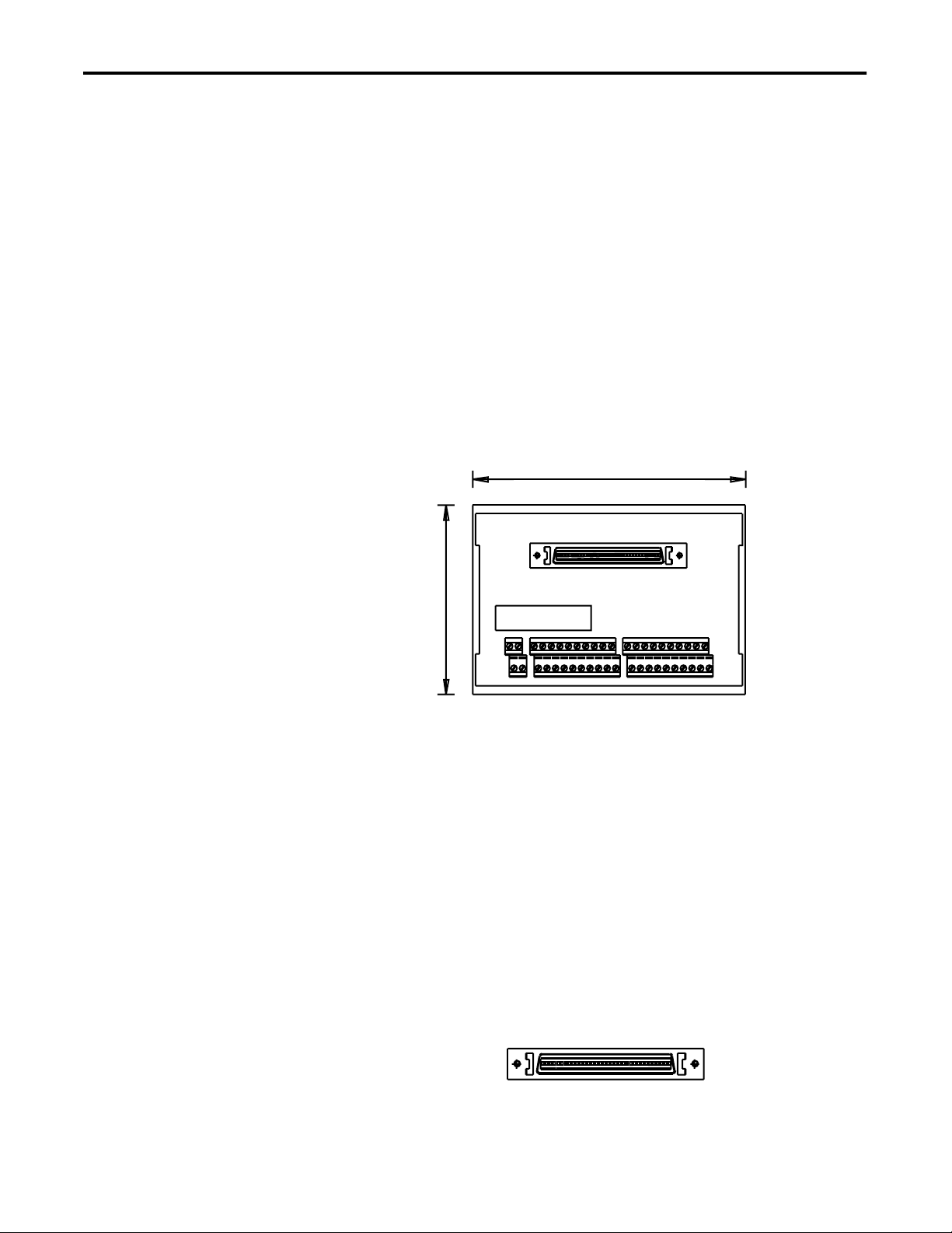
The following diagram identifies the connection for the cable to the
PCI 2 Axis Servo Card and the connections for wiring two axes.
Figure 1 1784-PM02AE-TP0x Termination Panel
P1
The connection marked P1 is for the cable from the PCI 2 Axis Servo
card. It accepts a straight 68 way Mini D shielded plug with a spring
latch. This connection is where the 1 meter or 3 meter premade cable
attaches to connect the termination panel to the PCI card. The cable is
packaged with the termination panel and shares the same catalog
number 1784-PM02AE-TP0x where x represents the length of the
cable.
1 Publication 1784-IN007A-EN-P - November 2000
Figure 2 1784-PM02AE-TP0x Cable Connection
Page 2
2
2 Axis Servo Card Termination Panel
P2
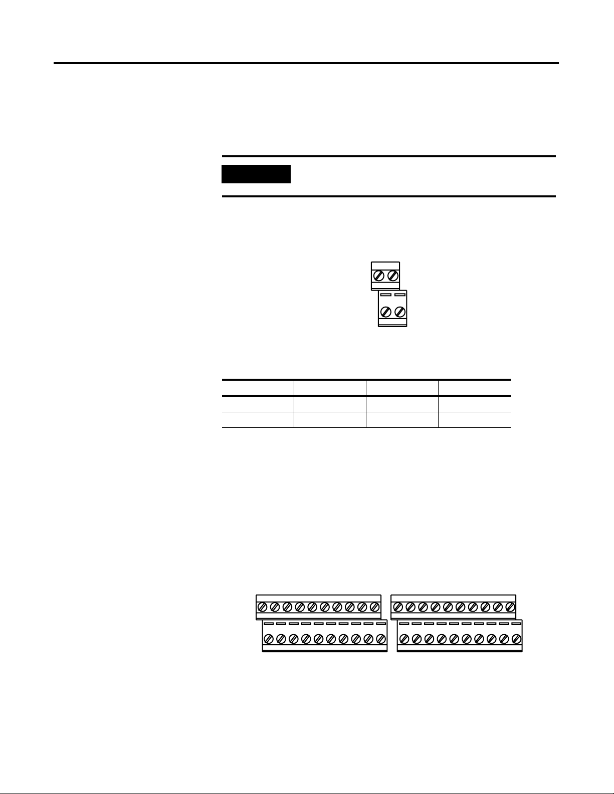
The P2 connection is for wiring the encoder power. Those marked B0
and B1 are for the Encoder power and those marked A0 and A1 are
the 0 volt connections.
IMPORTANT
External encoder power should not be connected if
the encoder is powered by another device.
Figure 3 P2 Connector
P2
B0 B1
A0 A1
P2 Function P2 Function
A0 Encoder 0V B0 Encoder Power
A1 Encoder 0V B1 Encoder Power
Publication 1784-IN007A-EN-P - November 2000
P3 and P4
The P3 and P4 receptacles are for wiring the axes. P3 is Axis 0 and P4
is Axis 1.
Figure 4 P3 and P4 Connectors
P3 P4
B0 B1 B2 B3 B4 B5 B6 B7 B8 B9
A0 A1 A2 A3 A4 A5 A6 A7 A8 A9
B0 B1 B2 B3 B4 B5 B6 B7 B8 B9
A0 A1 A2 A3 A4 A5 A6 A7 A8 A9
Page 3
2 Axis Servo Card Termination Panel
P3 & P4 Function P3 & P4 Function
A0 DRVFLT B0 +CHA
A1 Home Area B1 -C HA
A2 Reg 1 B2 +CHB
A3 Reg 2 B3 -CHB
A4 OK B4 +CHZ
A5 IN_COM B5 -CHZ
A6 Enable+ B6 Screen
A7 Enable- B7 +Out
A8 Encoder 0V B8 -Out
A9 Chassis B9 Encoder Pwr
3
Mounting the Termination
Panel
Termination Panel Cable
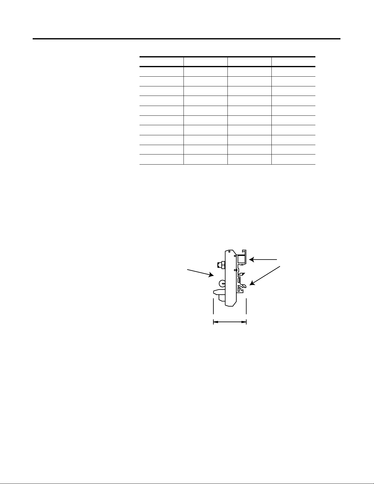
The termination panel mounts to a DIN rail using the mounting feet
on the back of the panel. The termination panel cable comes in two
lengths; 1 meter and 3 meters. Therefore the termination panel can be
mounted no more than 3 meters from the back of the PC containing
the PCI 2 Axis Servo Card.
Figure 5 DIN Rail Assembly for Termination Panel
Termination
Mounting Feet
Panel
45.00 mm
The 1784-PM02AE card is connected to the termination panel via a
premade 34 pair, 28 AWG SCSI shielded cable. The cable is available
in lengths of 1 meter and 3 meters. The cable comes shipped with the
termination panel and its catalog number is tied to the termination
panel where the ending x stands for the cable length of either 1 meter
or 3 meters.
Publication 1784-IN007A-EN-P - November 2000
Page 4

4
2 Axis Servo Card Termination Panel
Figure 6 1784-PM02AE-TP0x Cable
68 Way
Connector
(PX)
68 Way
Backshell
Cable type = 34 pair, 28AWG SCSI Shielded cable
68 Way
Backshell
68 Way
Connector
(PY)
Catalog Numbers for premade Servo card to termination panel cables.
Allen-Bradley Catalog
Number
1784-PM02AE-TP01 1m
1784-PM02AE-TP03 3m
Pinouts for Cable
1784-PM02AE-TP
Length in
meters
0x
Pin
(PX)
Pin Pair
Number
Pin Description Pin
(PY)
1 Pair 1 +CH A Feedback Input Axis 0 1
35 -CH A Feedback Input Axis 0 35
2 Pair 2 +CH B Feedback Input Axis 0 2
36 -CH B Feedback Input Axis 0 36
3 Pair 3 +CH Z Feedback Input Axis 0 3
37 -CH Z Feedback Input Axis 0 37
4 Pair 4 +OUT, Axis 0 4
38 -OUT, Axis 0 38
5 Pair 5 DRVFLT, Axis 0 5
49 HOME, Axis 0 49
6 Pair 6 REG1, Axis 0 6
40 REG2, Axis 0 40
7 Pair 7 +ENABLE, Axis 0 7
41 -ENABLE, Axis 0 41
8 Pair 8 OK 1 8
42 IN_COM, Axis 0 42
Publication 1784-IN007A-EN-P - November 2000
Page 5

2 Axis Servo Card Termination Panel
5
Pin
(PX)
Pin Pair
Number
Pin Description Pin
(PY)
9 Pair 9 IN_COM, Axis 0 9
43 IN_COM, Axis 1 43
10 Pair 10 +CH A Feedback Input Axis 1 10
44 - CH A Feedback Input Axis 1 44
11 Pair 11 +CH B Feedback Input Axis 1 11
45 -CH B Feedback Input Axis 1 45
12 Pair 12 +CH Z Feedback Input Axis 1 12
46 -CH Z Feedback Input Axis 1 46
13 Pair 13 +OUT, Ax is 1 13
47 -OUT, Axis 1 47
14 Pair 14 DRVFLT, Axis 1 14
48 HOME, Axis 1 48
15 Pair 15 REG1, Axis 1 15
49 REG2, Axis 1 49
16 Pair 16 +ENABLE, Axis 1 16
50 -ENABLE, Axis 1 50
17 Pair 17 OK 2 17
51 IN_COM, Axis 1 51
Publication 1784-IN007A-EN-P - November 2000
Page 6

6
2 Axis Servo Card Termination Panel
Sample Wiring Diagram
This is a general wiring example of the 1398 to the termination panel.
Figure 7 Wiring from a 1398 to the T e rmination Panel
From 1398
1398-CFLAExx
Axis 0
1398-CFLAExx
NC
NC
-CHA
+CHA
+CHB
P2 P3
B0 B1
B0 B1 B2 B3 B4 B5 B6 B7 B8 B9
A0 A1 A2 A3 A4 A5 A6 A7 A8 A9
A0 A1
Reg Input
NC
Home Input
NC
-CHB
+CHZ
-CHZ
Shield
Axis 0
1398-CFLAExx
-OUT
+OUT
NC
+CHA
-CHA
+CHB
Axis 1
-CHB
+CHZ
P4
B0 B1 B2 B3 B4 B5 B6 B7 B8 B9
A0 A1 A2 A3 A4 A5 A6 A7 A8 A9
NC
24V
24V Com
NC
to 24V
Ready -
Ready +
+ENABLE
Estop String
24 V Com
Shield
24V DC
24V Com
Brake +
Brake -
Reset
Reg Input
Home Input
NC
Estop String
Shield
-CHZ
24V
24V Com
to 24V
Ready +
Axis 1
1398-CFLAExx
-OUT
+OUT
Ready -
+ENABLE
NC
24 V Com
NC
Shield
24V DC
24V Com
Brake +
Brake -
Reset
Publication 1784-IN007A-EN-P - November 2000
1398-CFLAExx
From 1398
Axis 0
Axis 0
1398-CFLAExx
Axis 1
1398-CFLAExx
Axis 1
1398-CFLAExx
Page 7

NOTES:
2 Axis Servo Card Termination Panel
7
Publication 1784-IN007A-EN-P - November 2000
Page 8

Publication 1784-IN007A-EN-P - November 2000
8
© 2000 Rockwell International Corporation. Printed in the U.S.A.
PN 957395-25
 Loading...