

Page 1

Installation Instructions
Device N et Sc an ne r Mo du le
Catalog Number 1771-SDN/C
Contents
Use this document as a guide to install your 1771-SDN/C Scanner
Module.
To: See page:
understand important user information below
prevent Electrostatic Discharge 3
identify related publications 3
understand module compatibili ty and main tenance 4
understand module enhancement s and features 4
identify external sc anner module features 6
understand soft ware and hardware requirements 8
set data rate switches for channels 1 and 2 10
set I/O chassis addressing mo de switches 11
set node address switches for channels 1 and 2 11
install your module into the chassis 13
connect to the DeviceNet network 14
understand how your module communi cates with the PLC
program your PL C-5 processor 16
configure your module for the DeviceNet™ network 25
use the Explicit Message Program Control feature 26
troubleshoot your module 35
For this reference information: See page:
Specifications 39
®
processor
16
Before you install your module you must know how to:
• program and operate an Allen-Bradley PLC processor
• install and configure devices on your DeviceNet network
1 Publication 1771- IN014B-EN-P - September 2001
Page 2
2 DeviceNet Scanner Module Catalog Number 1771-SDN/C
Important User Information
Because of the variety of uses for the products described in
this publication, those responsible for the application and use
of these products must satisfy themselves that all necessary
steps have been taken to assure that each application and use
meets all performance and safety requirements, including any
applicable laws, regulations, codes and standards.
In no event will Allen-Bradley be responsible or liable for
indirect or consequential damage resulting from the use or
application of these products.
Any illustrations, charts, sample programs, and layout
examples shown in this publication are intended solely for
purposes of example. Since there are many variables and
requirements associated with any particular installation,
Allen-Bradley does not assume responsibility or liability (to
include intellectual property liability) for actual use based
upon the examples shown in this publication.
Allen-Bradley publication SGI-1.1, Safety Guidelines for the
Application, Installation and Maintenance of Solid-State
Control (available from your local Allen-Bradley office),
describes some important differences between solid-state
equipment and electromechanical devices that should be taken
into consideration when applying products such as those
described in this publication.
Reproduction of the contents of this copyrighted publication,
in whole or part, without written permission of Rockwell
Automation, is prohibited.
ATTENTION
ATTENTION
!
!
IMPORTANT
Identifies information about practices or
circumstances that can lead to personal
injury or death, property damage, or
economic loss.
Identifies information that is critical for
successful application and understanding of
the product.
Environment and Enclosure
ATTENTION
ATTENTION
!
!
This equipment is intended for use in a
Pollution Degree 2 industrial environment,
in overvoltage Category II applications (as
defined in IEC publication 60664-1), at
altitudes up to 2000 meters without
derating.
This equipment is considered Group 1,
Class A industrial equipment according to
IEC/CISPR Publication 11. Without
appropriate precautions, there may be
potential difficulties ensuring
electromagnetic compatibility in other
environments due to conducted as well as
radiated disturbance.
Throughout this publication, notes may be used to make you
aware of safety considerations. The following annotations and
their accompanying statements help you to i dentif y a potential
hazard, avoid a potential hazard, and recognize the
consequences of a potential hazard:
Identifies information about practices or
WARNING
circumstances that can cause an explosion
in a hazardous environment, which may
lead to personal injury or death, property
damage, or economic loss.
!
This equipment is supplied as "open type"
equipment. It must be mounted within an
enclosure that is suitably designed for those
specific environmental conditions that will
be present and appropriately designed to
prevent personal injury resulting from
accessibility to live par ts. The inter ior of the
enclosure must be accessible only by the
use of a tool. Subsequent sections of this
publication may contain additional
information regarding specific enclosure
type ratings that are required to comply
with certain product safety certifications.
See NEMA Standards publication 250 and
IEC publication 60529, as applicable, for
explanations of the degrees of protection
provided by different types of enclosure.
Also, see the appropriate sections in this
publication, as well as the Allen-Bradley
publication 1770-4.1 ("Industr ial Automation
Wiring and Grounding Guidelines"), for
additional installation requirements
pertaining to this equipment.
Publication 1771-IN014B-E N-P - September 2001
Page 3

DeviceNet Scanner Module Catalog Num ber 1771-SDN/C 3
Prevent Electrostatic Discharge
Where to Find More Information
.
ATTENTION
ATTENTION
!
!
The following table describes related documentation. To order a copy
or to view or download an online version, visit The Automation
Bookstore at:
This equipment is sensitive to electrostatic discharge
which can cause internal damage and affect normal
operation. Follow these gui delin es when you handle
this equipment:
• touc h a gro unded object to di scharge potentia l
static
• wear an approved grounding wrist strap
• do not to uc h c onnectors or pins on component
boards
• do not to uc h c i rcuit compo nents inside t he
equipment
• if available, use a static-safe workstation
• when not in use, store the equipment in
appropriate static-safe packaging
www.theautomationbookstore.com
For information about: See this document: Publication number:
Configuring the scanner
module and associated
hardware in an exa m ple
application
Performing the ControlFlash
Update
RSLogix 5™ software Getting Results with RSLogix 5 9399-RL53GR
RSLinx™ software Getting Results with RSLinx 9399-WAB32GR
RSNetWorx for DeviceNet™
software
Connecting the DeviceNet
network
1771-SDN DeviceNet Scanner
Module User Manual
ControlFlash Firmware Upgrade
Kit User Manual
RSNetWorx for DeviceNet Demo
CD
DeviceNet Cable Planning and
Installation Manual
1771-6.5.132
1756-6.5.6
9398-DNETDEMO
DN-6.7.2
Publication 1771- IN014B-EN-P - September 2001
Page 4
4 DeviceNet Scanner Module Catalog Number 1771-SDN/C
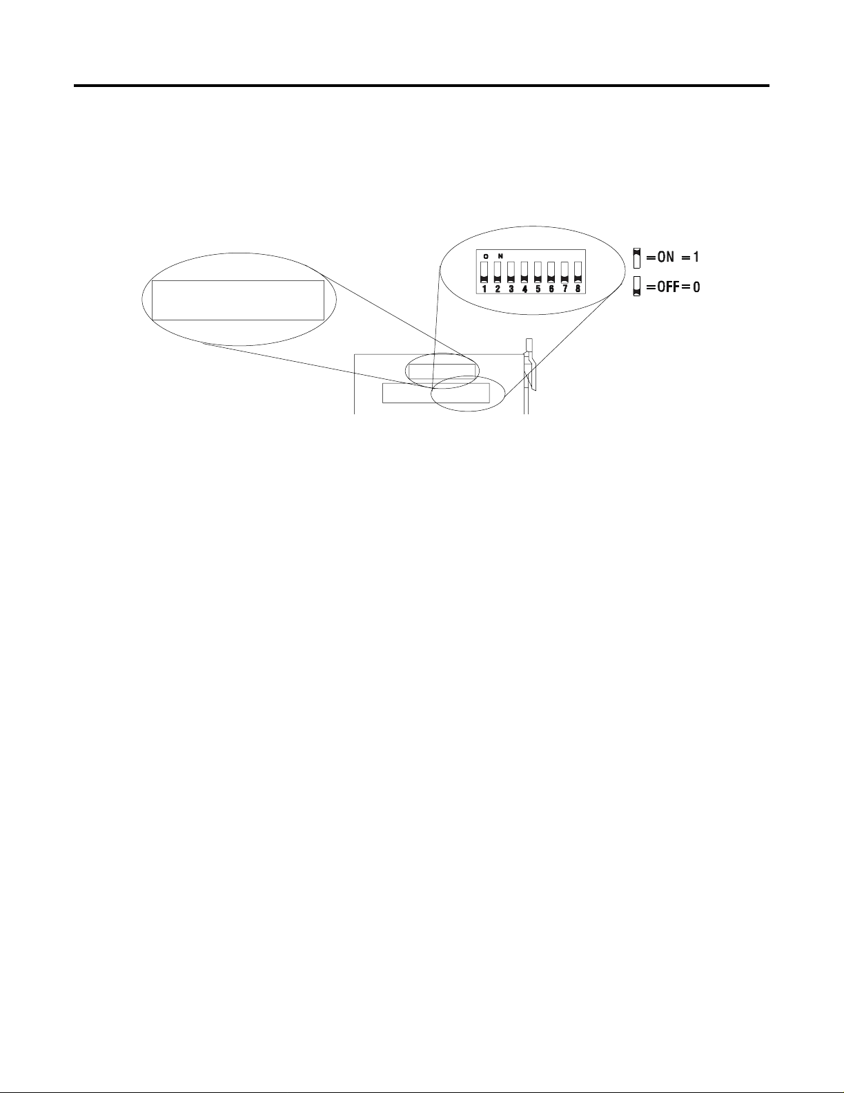
Module Compatibility and Maintenance Requirements
Series C label
NOTE: Default scanner setting is Series C operation.
When replacing an older scanner , se t
configuration Switch 5 to the OFF position.
See Installation Instructions for details.
The 1771-SDN/C DeviceNet Scanner Module is fully compatible with
the Series A and Series B vers ions . You can use the Ser ies C vers ion as
a spare or replacement module with one requirement: you must
change the postion of Switch 5 to the off or “0” position in the
Configuration switchbank as show n bel ow :
Configuration
Chassis Address
The scanner revision is identified by RSNetWorx. In Series B mode,
the scanner is identified as Series B with major number as 4 and minor
number as 50. In Series C mode, the scanner is identified as Series C
with major number as 6 and minor number as 2 or higher.
To use the Series C module enhancements listed below, the scanner
module Configuration Switch 5 must be set in the on or “1” position.
Module Enhancements
Updated DeviceNet Master Library
Electronic Keying - added to include Major and Minor revision
checking.
Shared Inputs - multiple scanner modules can acquire the inputs
from a specific input device without using separate connections.
Auto Device Replacement (ADR) - consists of No de Recovery and
Configuration Recovery:
• Node Recovery - this feature causes the node number of the
replacement device to be automatically changed to the node
number of the original device. The replacement device’s node
number must be writable over the DeviceNet network and must
initially be set to 63.
• Configuration Recovery - this feature causes the replacement
device’s configuration to be made identical to the original device.
The replacement device’s configuration must be writable over the
DeviceNet network. Configuration Recovery files are stored in the
master scanner that is communicating with the original device
through RSNetWorx for DeviceNet.
Publication 1771-IN014B-E N-P - September 2001
Page 5

DeviceNet Scanner Module Catalog Num ber 1771-SDN/C 5
Other Features
Change of State
Change of state enables the scanner module to perform a scan:
• whenever a network data change occurs, or
• at a user-configurable heartbeat rate
Because data is only sent on an as-needed basis, this feature increases
system performance by reducing network traffic.
Cyclic I/O
Cyclic I/O allows you to instruct the scanner module to perform a
scan at a spe c ific se nd rate.
Because data is only sent at a periodic rate, this feature increases
system performance by reducing network traffic.
Pass-Through
The 1771-SDN “pass-through” feature allows communication with the
DeviceNet network from another network. This feature can be used to
adjus t an d f i ne t une the nodes on your network.
For more information on how to use the pas s-throu gh feature, refer to
Chapter 5 of the PLC-5 DeviceNet Scanner Module User Manual,
publication 1771-6.5.132.
Publication 1771- IN014B-EN-P - September 2001
Page 6
6 DeviceNet Scanner Module Catalog Number 1771-SDN/C
External Module Features
Module Status Indicator - indicates
MODULE
STATUS
CHANNEL 1
NETWORK
STATUS
NODE/
ERROR CODE
DeviceNet
RESET
whether the device has power and
is functioning properly
Reset Button - resets your module.
Channel 1 Status Indicator - gives
diagnostic indications for Channel 1.
Node Address and Status Display displays numeric codes that indicate
scanner node address, status and/or
errors for Channel 1.
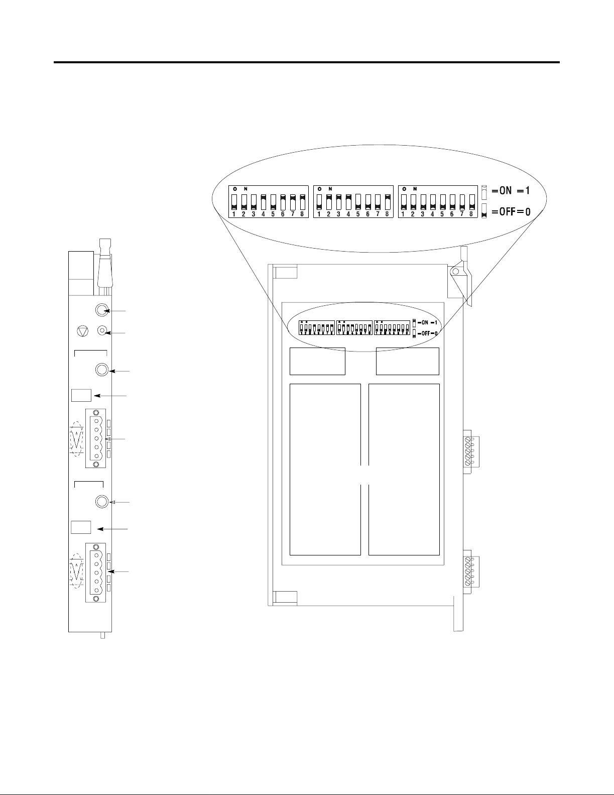
Use the drawing below to identify the featu res of t he 1771-SDN/C and
B versions of the Scanner Module.
Multi-position Switchesuse to set the data rate, chassis addressing mode
and scanner node address for each channel.
CHANNEL 1 CHANNEL 2 CONFIGURATION
Data Rate
Switch Settings
Chassis Address
Switch Settings
CHANNEL 2
NETWORK
STATUS
NODE/
ERROR CODE
DeviceNet
Allen-Bradley
1771-SDN
Front of Module
DeviceNet Port 1 - use the color-coded
header to wire your module.
Channel 2 Status Indicator - gives
diagnostic indications for Channel 2.
Node Address and Status Display displays numeric codes that indicate
scanner node address, status and/or
errors for Channel 2.
DeviceNet Port 2 - use the
color-coded header to wire your
module.
20274
Channel 1 & 2
Node Address Switch Settings
Left Side of Module
20275
Publication 1771-IN014B-E N-P - September 2001
Page 7
DeviceNet Scanner Module Catalog Num ber 1771-SDN/C 7
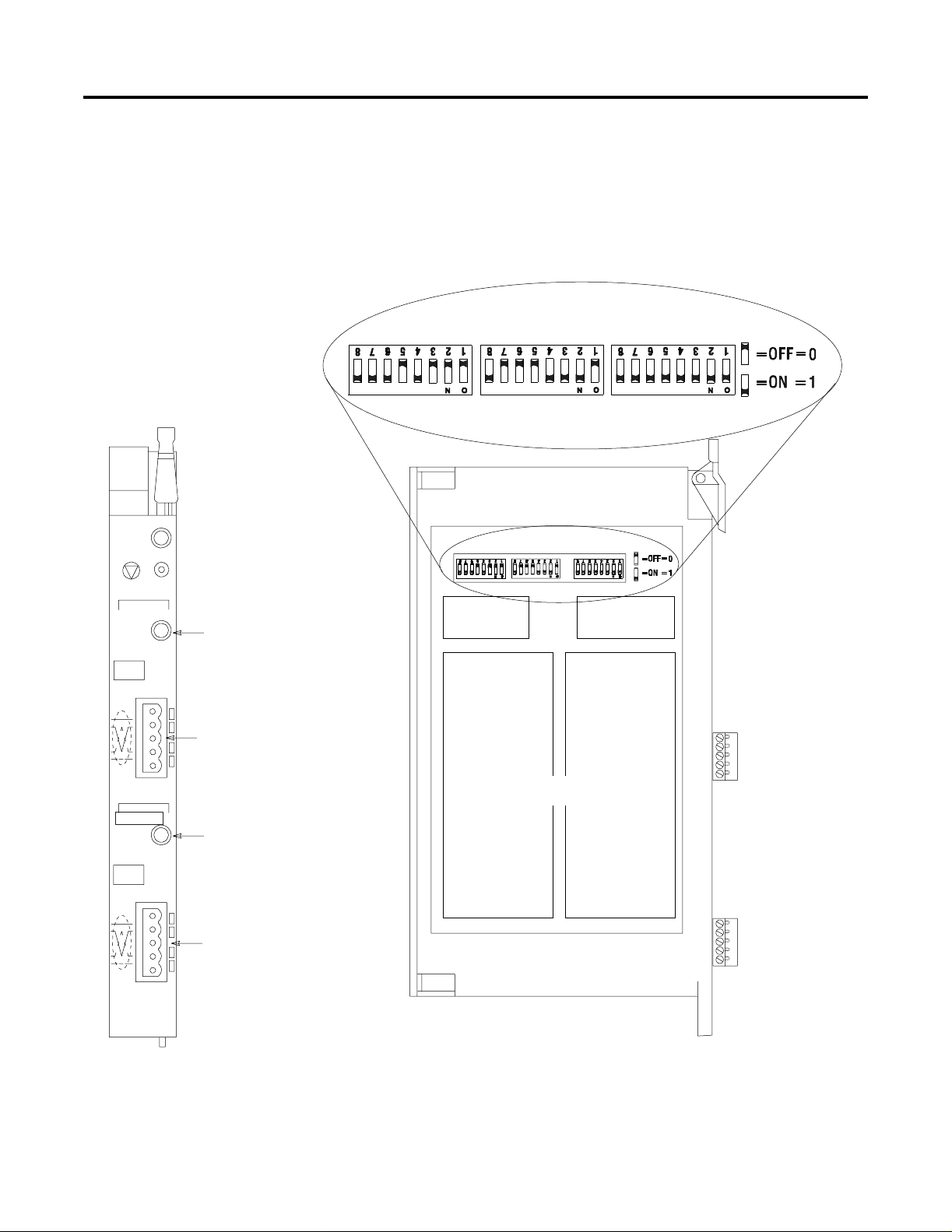
Series A Channel, Port and Switch Identification
The Series A version of this module (1771-SDN) uses different
channel, port and switch identification as shown in the following
figure:
Multi-position Switchesuse to set the data rate, chassis addressing mode
and scanner node address for each channel.
Channel A
Channel B
Channel A Status Indicator gives diagnostic indications for
Channel A.
DeviceNet Port A - use the
color-coded header
to wire your module.
Channel B Status Indicator gives diagnostic indications for
Channel B.
DeviceNet Port B - use the
color-coded header to wire your
module.
CHANNEL A CHANNEL B CONFIGURATION
Data Rate
Settings
Channel A & B
Node Address Settings
AddressChassis
Settings
Front of Module
20274
Left Side of Module
20275
Publication 1771- IN014B-EN-P - September 2001
Page 8

8 DeviceNet Scanner Module Catalog Number 1771-SDN/C
Software and Hardware Requirements
Software Requirements
Before you intall the scanner module, make sure you have the
followi ng software:
• personal computer with Microsoft Windows™ 95 or later
operating system
• RSNetWorx for DeviceNet software, version 2.22 or later
• RSLogix 5 software
Electronic Data Sheet Requirement
To use the new features of this release, the scanner module requires
the latest EDS file for RSNetWorx for DeviceNet software. If the
software displays the device as an “unknown device”, you must
download the current EDS file.
You can get the latest EDS file online at:
http://www.ab.com/networks/eds
Once you are at this location:
1. Select
2. Enter the catalog number: 1771-SDN
3. Select Search
DeviceNet
Hardware Requirements
The 1771-SDN Scanner Module is compatible only with the 1771-A1B
through 1771-A4B or later I/O chassis in any configuration supported
by the 1771 family.
Y ou can use the following chassis with the 17 71-SDN Scanner Module:
• Local I/O Chassis with only the PLC processor running in the
leftmost slo t
• Extended Local I/O Chassis with any 1771-ALX Adapter Module
running in the leftmost slot
• Remote I/O Chassi s with a 1 771-ASB Adapter Module ru nning i n
the leftmost slot or a PLC processor running in the leftmost slot
Publication 1771-IN014B-E N-P - September 2001
Page 9

DeviceNet Scanner Module Catalog Num ber 1771-SDN/C 9
• Remote I/O Chassis linked to ControlNet with a 1771-ACN(R)
running in the leftmost slot
Do not use the 1771-SDN Scanner Module with the following:
• Chassis configured for complementary I/O
• Remote I/O chassis connected to a preceding chassis using a
1771-SN Sub I/O Scanner Module
IMPORTANT
The 1771-SDN Scanner Module fits in any slot of the
chassis except for the leftmost slo t, which is reserv ed
for the PLC processor. The scanner module will not
conflict with other 1771 I/O devices in the chassis.
You can install multiple scanners in the same chassis.
The 1771-SDN Scanner Module is compatible wit h any PLC-2
or PLC-5
processor that supports block transfer read and write
, PLC-3
instructions. The example configurations in these installation
instructions use a PLC-5 processor.
Perform the ControlFLASH Update
If you have the previous releas e of fi rmware and you want to up grade
it to this release, you must perform the ControlFLASH update. To get
the kit, contact Rockwell Automation Technical Support at
440.646.5800. To install the kit, refer to the ControlFLASH Firmware
Upgrade Kit User Manual, publication 1756-6.5.6.
Before you install your module you must set the following switches:
• data rate for each DeviceNet channel
• I/O cha ssi s a d dressing mode (1 /2, 1 or 2-sl o t ad dressing )
• scanner node address for each channel
Publication 1771- IN014B-EN-P - September 2001
Page 10
10 DeviceNet Scanner Module Catalog Number 1771-SDN/C
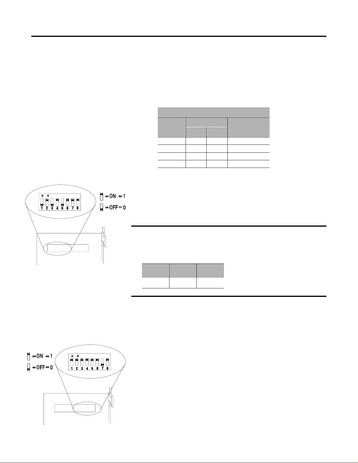
Set the Data Rate Switches for Channels 1 and 2
Channel 1
Data Rate
To set the DeviceNet data rate switches for Channels 1 and 2:
1. Locate the swit chbank label ed “Cha nnel 1” on t he lef t side of the
module.
2. Use the table below to determine the data rate you want to set
for “Channel 1.” Record your choice in the fourth column.
Channel 1 and 2
Data Rate
Switch Position
1 2
125K baud 0 0
250K baud 0 1
500K baud 1 0
Not allowed 1 1
Note Your
Data Rate
3. Using a ball point pen or similar object, adjust switches 2 and 1
to your desired data rate setting. (NOTE: Do not use a pencil
to adjust switches. The lead may break off in the
switchbank.) Slide the switches up to denote an on or “1”
position. Slide the switches down to denote an off or “0”
position.
20276
Configuration
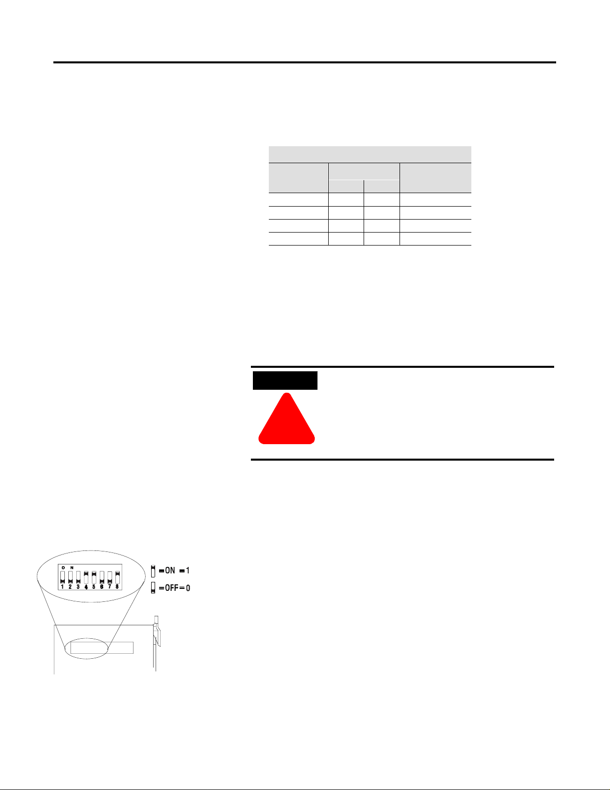
Set the I/O Chassis Addressing Mode Switches
Chassis Address
For example, if you want to set DeviceNet data rate of 500K baud for
Channel 1, then you set switch 2 to an off or “0” position and switch 1
to an on or “1” position.
Data Rate Sw.1 Sw.2
500K 1 0
4. Repeat steps 1-3 to set the DeviceNet data rate for Channel 2,
using the switchbank labeled “Channel 2’. Adjust the switches to
your desired data rate setting.
To set the I/O chassis addressing mode switches:
1. Locate the switchbank labeled “Configuration” on the left side of
the module.
2. Use the following table to determine the chassis addressing
mode you want to set. Record your choice in the fourth column.
20277
Publication 1771-IN014B-E N-P - September 2001
Page 11
DeviceNet Scanner Module Catalog Number 1771-SDN/C 11
Note: The scanner module consumes/produces 8 bits of discrete
output/input for t he processo r co nnection . The re fore, the scanner
module cannot be placed next to a 16-point module when using
1-slot ad dr e ssi n g.
I/O Chassis Addressing Mode
Mode
2-slot 0 0
1-slot 0 1
1/2-slot 1 0
Not allowed 1 1
3. Using a ball point pen or similar pointed object, adjust switches
7 and 8 to your desired chassis addressing mode. Slide the
switches up to denote an on or “1” position. Slide the switches
down to denote an off or “0” position. Make sure switches 1
through 4 and 6 in the switc hbank l abeled “ Config uratio n”
always remain in the off or “0” position. For Series C
functionality, make sure switch 5 is in the on or “1”
position.
Switch Position
7 8
Note Your
Mode
Set Node Address Switches for Channels 1 and 2
Channel 1
Node Address
20276
ATTENTION
ATTENTION
!
!
For more information about addressing, refer to your PLC processor
system level installation manual and design manual.
To set the scanner DeviceNet node address:
1. Locate the switchbank labeled “Channel 1”, on the left side of
the m odule.
2. Use th e following tab le to determine the node add ress you want
to set for the module on Channel 1, and note your choice. The
address range is 0 to 63.
3. Using a ball point pen or similar object, adjust switches 3
through 8 to your desired node address settings. Slide the
switches up to denote an on or “1” position. Slide the switches
down to denote an off or “0” position.
4. Using a ball point pen or similar object, adjust switches 3
through 8 to your desired node address settings. Slide the
switches up to denote an on or “1” position. Slide the switches
down to denote an off or “0” position.
The I/O chassis addr e ss se t t ing must match
the chassis addressing mode setting for the
1771 chassis. If the switches do not match,
data will be lost in the data transfer between
the PLC-5 processor and the scanner module.
Publication 1771- IN014B-EN-P - September 2001
Page 12

12 DeviceNet Scanner Module Catalog Number 1771-SDN/C
5. Repeat steps 1–3 to set the scanner node addres s f or Channel 2,
using the switchbank labeled “Channel 2”. Adjust the switches to
your desired node address setting.
IMPORTANT
The node address setting for DeviceNet Channel 1 must
not conflict with the node address of any other device on
the network.
Channel 1 and 2 Node Address Channels 1 and 2 Node Address
Node
Address
0 0 0 0 0 0 0 32 1 0 0 0 0 0
1 0 0 0 0 0 1 33 1 0 0 0 0 1
2 0 0 0 0 1 0 34 1 0 0 0 1 0
3 0 0 0 0 1 1 35 1 0 0 0 1 1
4 0 0 0 1 0 0 36 1 0 0 1 0 0
5 0 0 0 1 0 1 37 1 0 0 1 0 1
6 0 0 0 1 1 0 38 1 0 0 1 1 0
7 0 0 0 1 1 1 39 1 0 0 1 1 1
8 0 0 1 0 0 0 40 1 0 1 0 0 0
9 0 0 1 0 0 1 41 1 0 1 0 0 1
10 0 0 1 0 1 0 42 1 0 1 0 1 0
11 0 0 1 0 1 1 43 1 0 1 0 1 1
12 0 0 1 1 0 0 44 1 0 1 1 0 0
13 0 0 1 1 0 1 45 1 0 1 1 0 1
14 0 0 1 1 1 0 46 1 0 1 1 1 0
15 0 0 1 1 1 1 47 1 0 1 1 1 1
16 0 1 0 0 0 0 48 1 1 0 0 0 0
17 0 1 0 0 0 1 49 1 1 0 0 0 1
18 0 1 0 0 1 0 50 1 1 0 0 1 0
19 0 1 0 0 1 1 51 1 1 0 0 1 1
20 0 1 0 1 0 0 52 1 1 0 1 0 0
21 0 1 0 1 0 1 53 1 1 0 1 0 1
22 0 1 0 1 1 0 54 1 1 0 1 1 0
23 0 1 0 1 1 1 55 1 1 0 1 1 1
24 0 1 1 0 0 0 56 1 1 1 0 0 0
25 0 1 1 0 0 1 57 1 1 1 0 0 1
26 0 1 1 0 1 0 58 1 1 1 0 1 0
27 0 1 1 0 1 1 59 1 1 1 0 1 1
28 0 1 1 1 0 0 60 1 1 1 1 0 0
29 0 1 1 1 0 1 61 1 1 1 1 0 1
30 0 1 1 1 1 0 62 1 1 1 1 1 0
31 0 1 1 1 1 1 63 1 1 1 1 1 1
3 4 5 6 7 8 3 4 5 6 7 8
Switch Position
Node
Address
Switch Position
Publication 1771-IN014B-E N-P - September 2001
Page 13

DeviceNet Scanner Module Catalog Number 1771-SDN/C 13
Install Your Module into the Chassis
Before you insert the module into the chassis, set all switches in
accordance with the requirements of your n etworks. Y ou must s et th e
switches before you install the the 1771-SDN Scanner Module or it will
not function properly.
WARNING
WARNING
If you ins e rt or re move the scan ne r module with
power applied to this module or any device on the
network, an electrical arc can occur. This could
cause an explosion in hazardous location
!
!
installations. Be sure that power is removed or the
area is nonhazardous before proceeding.
1. Se lect a s lot for the module in the chassis. You may use any sl ot
except the leftmost slo t, w hich i s r ese rved for the PLC processor.
2. Adjust the chassis’ keying bands (see figures below).
The 1771-SDN Scanner Module uses keying bands to prevent
placi ng modul es into t he wrong sl ot. You c an key any c onnect or
in an I/O chassis to receive the module except for the leftmost
connector, which is reserved for adapter or processor modules.
The 1771-SDN Scanner Module is slotted in two places on the
rear edge of the circuit board. These slots are intended to
mate with the plastic keying bands supplied with the I/O
chassis.
I/O chassis
backplane connector
Scanner module
Position the keying bands in the backplane connectors to
correspond to the key slots on the module.
I/O chassis
2
4
6
8
10
Place the keying bands:
between 2 and 4
between 22 and
You can change the position of these bands if subsequent system design and
rewiring makes insertion of a different type of module necessary.
24
keying bands
2
4
6
8
10
12
14
16
18
20
22
24
26
28
19808
Publication 1771- IN014B-EN-P - September 2001
Page 14

14 DeviceNet Scanner Module Catalog Number 1771-SDN/C
3. Insert the 1771-SDN Scanner Module into the slot you have
selected.
4. Apply firm, even pressure to seat the module in the I/O chassis
backplane connectors.
5. Swing the locking bar down until locked in place to make sure
that you have secured t h e module in the slot.
Locking Bar
20278
Connect to the DeviceNet Network
To connect to the DeviceNet network:
WARNING
WARNING
!
!
If you ins e rt or re move the scan ne r module with
power applied to this module or any device on the
network, an electrical arc can occur. This could
cause an explosion in hazardous location
installations. Be sure that power is removed or the
area is nonhazardous before proceeding.
Locking Bar
20279
Publication 1771-IN014B-E N-P - September 2001
Page 15

DeviceNet Scanner Module Catalog Number 1771-SDN/C 15
1. Connect th e DeviceNet drop line to the li near plug, by matching
the wire insulation colors to the colors shown on the label:
Module label shows
wiring color scheme:
+24V RED
Can_H WHITE
Drain/Shield
Can_L BLUE
+24V Return BLACK
Ten-pin
Linear
Plug
Red
White
Bare (shield)
Blue
Black
DeviceNet
Drop Line
Front of Scanner Module
2. Locate the DeviceNet
Port 1 connector for Channel 1 on the
front of the module.
3. Insert the linear plug into the five-pin header for
Channel 1.
DeviceNet Port 1
for Channel 1
Red
White
Bare (shield)
Blue
Black
Five-Pin
Header
DeviceNet
Drop Line
4. Repeat steps 1–3 for Channel 2, if necessary.
20298
20298
Module installation is complete. To operate the module,
you must program the PLC processor to communicate with it. In the
following two sections, we describe how your module communicates
with the PLC-5 processor and how to program your processor.
WARNING
WARNING
If you connect or disconnect the DeviceNet cable
with power applied to this module or any device on
the network, an electrical arc can occur. This could
cause an explosion in hazardous location
!
!
installations. Be sure that power is removed or the
area is nonhazardous before proceeding.
Publication 1771- IN014B-EN-P - September 2001
Page 16

16 DeviceNet Scanner Module Catalog Number 1771-SDN/C
How Your Module Communicates with the PLC-5 Processor
The 1771-SDN scanner module uses four methods to transfer data,
status and command information between the scanner and the PLC-5:
• DIO points for high-speed discrete outputs
• DIO points for high-speed discrete inputs
• BTW to send output data to the scanner
• BTR to upload input data from the scanner
Using DIO Points for High-Speed Discrete Inputs and Outputs
The foll owing table describes chassis addressin g modes and the
number of discrete inputs and outputs assigned to the 1771-SDN
Scanne r Module slot .
Addressing Mode Discrete Inputs Discrete Outputs
1/2-slot 24 24
1-slot 8 8
2-slot 0 0
Program Your PLC-5 Processor
These inputs and outputs will appear in the PLC I/O image table in
the location corresponding to the rack, group and slot the module is
plugged into. Since the bits are in the I/O table, they can be forced.
For more information about chassis addressing modes, refer to your
PLC-5 processor system level installation manual.
You must pr ogram your PLC -5 processor so it commun i c a t e s with the
1771-SDN Scanner Module. Communication is possible when you
program your processor through multiple block transfer instructions.
The scanner uses the size of the block transfer to map the block
transfer data words into the scanner’s internal data table. The scanner
module accepts blocks of different sizes and knows that each block
has a different meaning.
PLC-5 block transfer instructions use one integer file in the data table
section for module location and other data to execute the instruction.
This is the control block file. The block transfer data file stores data
that you want to transfer to your mod ule (wh en pr ogra mmin g a bl ock
transfer write (BTW)) or from your module (when programming a
block transfer read (BTR)). The address of the block transfer data file
is stored in the control block file.
Publication 1771-IN014B-E N-P - September 2001
Y ou must select a separate data file for each of the block transfer
instructions. You must also use separate 5-word block transfer
Page 17

DeviceNet Scanner Module Catalog Number 1771-SDN/C 17
control files for each of the block transfer in structio ns when an
integer file is used. This is not necessary when a control block file is
a BT data type.
To make sure the ins truction is reset af ter the block tr ansfer completes
and recyc les , y ou mus t use enab le bits as th e cond i tio ns on e ach r ung
with the PLC-5. The following figure shows a PLC-5 sample program
.
IMPORTANT
The module does not support continuo us mode block
transfer. Set Continuous to NO for eac h BTW or BTR .
Precondition
Precondition
Block-transfer rungs must be scanned for the transfers to occur. The
preconditions allow time-driven or event-driven transfers.
BT10:0
BTR
enable bit
BTW
enable bit
BT10:5.EN
BT10:5.EN
EN
EN EN
EN
BTW
enable bit
BTR
enable bit
BT10:0
BTR
BLOCK TRANSFER READ
Rack
Group
Module
Control Block
Data file
Length
Continuous NO
BTW
Rack
Group
Module
Control Block
Data file
Length
Continuous
BT10:0
N11:0
62
BT10:5
N11:62
62
NO
EN
3
2
DN
0
ER
ENBLOCK TRANSFER WRITE
3
2
DN
0
ER
Publication 1771- IN014B-EN-P - September 2001
Page 18

18 DeviceNet Scanner Module Catalog Number 1771-SDN/C
When using rungs like those in the preceding figure, the processor
alternates between the BTR and the BTW , waiting to request the next
block transfer until the previous block transfer is completed. When
only one block transfer is active at a time, it is considered a
single- thr eaded bloc k t ransf er. Sing l e-th reade d blo ck t ran sf ers op erat e
in an orderly sequence of read and write, however, they are slower
than the asy nc hronous method, shown bel ow:
Precondition
Precondition
Block-transfer rungs must be scanned for the transfers to occur. The
preconditions allow time-driven or event-driven transfers.
BT10:0
EN
BTR
enable bit
BTW
enable bit
BT10:5.EN
EN
BTR
BLOCK TRANSFER READ
Rack
Group
Module
Control Block
Data file
Length
Continuous NO
BTW
Rack
Group
Module
Control Block
Data file
Length
Continuous
BT10:0
N11:0
62
BT10:5
N11:62
62
NO
EN
3
2
DN
0
ER
ENBLOCK TRANSFER WRITE
3
2
DN
0
ER
As soon as an asynchronous block transfer completes, it is requested
again, independent of other block transfers going to th e same module.
If you have programmed many block tran sfers to the same logical rack
(especially a remote rack), you will fill the processor’s queue. In this
situation, the asynchronous method can result in irregular timing
between successive executions of the same block transfer.
For more information on programming and block transfers, refer to
your PLC-5 Programming Software Instruction Set Reference Manual,
publication 1785-6.1.
Using BTW to Send Outputs to the Scanner
The PLC-5 downloads output data to the scanner using block
transfer write instructi ons over the 1771 backplane. The scanner
module can update a maximum of 357 output words by internally
linking together six different sized block transfers as shown in the
following table.
Publication 1771-IN014B-E N-P - September 2001
Page 19

DeviceNet Scanner Module Catalog Number 1771-SDN/C 19
Block
Transf er Size
62 words Block 62
61 words Block 61 Words 62–122
60 words Block 60 Words 123–182
59 words Block 59 Words 183–241
58 words Block 58 Words 242–299
57 words Block 57 Words 300–356
1-50 words Block 1-50 Words 0-49
Accessed
Scanner Output
Block
Scanner Output Data Table
Word 0 – Module Command Register Word
Words 1–61
Each indi vidual bl ock transfer is independent, but alwa y s updates t he
same output bytes in the scanner’s memory table. Of the scanner
output words 0 through 61, the word 0 is reserved for the Module
Command Register. Block transfer sizes 1 through 50 update scanner
output words 0 through 49, thus reducing the required BTW time
when 50 or fewer output words are needed. Sizes 51 thru 56 are
illegal and size 64 is used for Explicit Message Program Control. For
more details on Explicit Message Program Control, refer to page 26.
If the scanner receives a BTW of 62 words, then it knows that it
contains the first block of the table. A BTW of 61 words, if necessary,
contains the second block of the table and so on for 60, 59, 58 and 57
words.
DeviceNet Messages
You determine the data that is exchanged with a given node on
channel 1 or 2 by creating custom configurations using RSNetworx
software version 2.22 or later. Refer to you r RSNetworx documentation
or online help and your 1771-SDN Scanner Configuration Manual
(publication number 1771-6.5.132) for more information on custom
configurations.
Module Command Register
The firs t word of the BTW downl oaded from th e PL C-5 to block 62 is
reserved as the module command register. The r egister is downloaded
with every 1 through 50 and 62 word block transfer write. This
modifies the scanner’s operation.
To execute a command, you set the appropriate bits in the module
command word, then perform a block transfer write to the first block
(the 62 word block) of the scanner output table. When the scanner
receives the command it immediately executes it. You latch bits 0
through 5 in your program to maintain the scanner’s desired state.
Publication 1771- IN014B-EN-P - September 2001
Page 20

20 DeviceNet Scanner Module Catalog Number 1771-SDN/C
The following table outlines the module command register’s bit
numbers and descriptions.
Module Command Register - Word 0, Block 62
Bit
Number
00 – 01
02 - 03
04
05
06
07
08 – 15
Bits
01 00
0 0 DeviceNet Channel 1
in idle mode
0 1 DeviceNet Channel 1
in run mode
1 0 DeviceNet Channel 1
in fault mode
11Reserved
0 0 DeviceNet Channel 2
in idle mode
0 1 DeviceNet Channel 2
in run mode
1 0 DeviceNet Channel 2
in fault mode
11Reserved
0 Enable DeviceNet
Channel 1
1 Disable DeviceNet
Channel 1
0 Enable DeviceNet
Channel 2
1 Disable DeviceNet
Channel 2
0 Scanner run
1 Scanner halt
0 Scanner Active
1 Sc anner reboot
0 Reserved for future use
Operating Mode Operating Mode Description
Idle
The scanner does not map output dat a to the devices, but keeps network
connections to devices open so device failures can be detected. Input data
is returned from devices, and mapped into the scanner input table and the
discrete inputs. Outputs on the network are not under program control and
will be in their configured ‘idl e st ate.’ The scanner must be put into this
mode to perform configuration of the scanner database tables.
Run
The scanner module maps output data from its scanner output table and
discrete outp uts to each device on the network. Inputs are received and
mapped into the scanner input table and discrete inputs. Outputs on the
network are un der program co ntrol.
Placing the PLC-5 into PROG or REM_PROG mode places the scanner into
idle mode regardless of the state of the bits in the module command
register. Placing the PLC-5 into RUN or REM_RUN mode causes the state
of the bits in th e modu le comma nd r egis te r to de termi ne the scanne r state.
Fault Network
The scanner stops communicating with devices on the network. No
outputs or inputs are mapped. O utputs on the network are not under
program control. If the scanner was in run, devices will go to their
configu red ‘fau lt st ate.’
Enable
The DeviceNet channel is enabled for communication. This is the normal
opera ting state of the channel.
Disable
The DeviceNet channel is disabled for communication. No communication
may occur over this channel. Outputs on the network are not under
program control. If the scanner was in run, devices will go to their
configured ‘fault state.’ Numeric error code 90 will occur when channel is
disabled.
Scanner Active
This is the normal operating mode of the scanner.
Scanner Halt
All scanner operations stop when this command is issued. No
communications occur over either DeviceNet port. No b lock transfer or
discrete I/O mapping occurs. Outputs on the network are not under
program control. If the scanner was in run, devices will go to their
configured ‘fault state.’ Numeric error code 97 will occur - you must reset
the scanner or cycle power to the scanner to recover from this state.
Scanner Reboot
This comman d ca uses th e s can ner to res et as th ou gh th e res et b utton ha d
been pressed. When this command is issued, all scanner communication
stops for the duration of the scanner’s initialization sequence. Outputs on
the network are no longer under program control. If the scanner was in
run, devices will go to their configured ‘fault state.’
Publication 1771-IN014B-E N-P - September 2001
Page 21

DeviceNet Scanner Module Catalog Number 1771-SDN/C 21
Use BTR to Upload Input Data from the Scanner
The PLC-5 uploads input data from the scanner using block transfer
read instructions over the 1771 backplane. The scanner interprets
BTRs of length 1 through 50 and 62 words as being from the first
block of the scanner input table. The scanner module can update a
maximum of 357 input words by internally linking together six
different sized block transfers. See the table below.
Block
Transf er Size
62 words Block 62
61 words Block 61 Words 62–122
60 words Block 60 Words 123–182
59 words Block 59 Words 183–241
58 words Block 58 Words 242–299
57 words Block 57 Words 300–356
52 words Block 52 Device Failure Table
51 words Block 51 Device Active Table
1-50 words Block 1-50 Words 0–49
Accessed
Scanner
Input Block
Scanner Input Data Table
Word 0 – Module Status Register Word
Words 1–61
Each ind i vidu al blo ck tr a nsf er is inde pend ent , but alwa ys re tri ev es the
same input bytes from the scanner’s input data table. The types of
information that a PLC-5 program will upload from the scanner via the
BTR are the:
• Device Input Data Table (6 blocks, 62 through 57 words)
• Device Failure Table (1 block, 52 words)
DeviceNet Messages
• Device Active Table (1 block, 51 words)
When the scanner receives a BTR, it automatically knows which block
of data is desired by the size specified.
Y ou may upload portions of the scanner input table rather than the
entire table, to support higher-speed operations. The scanner will
interpret any BTR of length 1 through 50 with the words 0 thru 49 of
block 62 of the scanner in put table. BTR s of sizes 57 through 61
represent full blocks of the table. A BTR of 52 words contains the
Device Failure Table . Sizes 53 through 56 are res erved. Size 64 is used
for Explicit Message Program Control. For more details on Explicit
Message Program Control, refer to page 26.
Publication 1771- IN014B-EN-P - September 2001
Page 22

22 DeviceNet Scanner Module Catalog Number 1771-SDN/C
To reduce block transfer time a nd i nc rease syst em performance, use
only the words you need.
Use the RSNetWorx for DeviceNet software to map data from a
DeviceNet node into the scanner input table. Data from a DeviceNet
node can be split and put into as many as four different locations in
the scanner input table.
Module Status Register
In the Module Status Register (word 0, block 62), bits 0 through 5
indicate to the PLC-5 the current state of the scanner module. When
a Module Comman d R egis ter c omm and is s ent t o the sc an ner mod ule ,
the respective bits are set in the Module Status Register when the
command executes. Depending on network load, the scanner may
take several moments to detect network status changes. The bits latch
on in the “on” state until the command clears.
Bits 6 and 7 indicate that you should read the device failure table for
more specific information about which devices failed. Bits 8 and 9
indicate that you should read the device autoverify table to determine
which device has incorrect device keying or a misconfigured data size
in the scanner configuration tables. Use the DeviceNetManager
software to correct this error.
You can use bits 6 and 7 of the Module Status Register to enable
the scanner module’s Module Command Register to react to certain
conditions. An example reaction to a condition is to keep the
communication ports in the “idle” mode until the bits clear.
When the bits clear, this indicates that all dev ices on the networks are
operational. When the devices are operational, you can put the ports
in the “run” mode, so that output data goes to the devices.
If a device failure is detected, you can put the communication into the
“idle” mode, so that all devices would go into t heir idl e state. You may
tie these inputs to the Module Command Register, so that you may use
them to adjust the operating mode of t he scanner when devices fail or
go online at startup.
You can also modify your control logic to run differently to
compensate for the loss of communication with a certain node.
An alarm message to alert an operator of the problem is also possible.
Publication 1771-IN014B-E N-P - September 2001
The following table lists Module Status Register bit numbers and their
descriptions.
Page 23

Bit
Number
00 - 01
02 - 03
04
05
06
07
08
09
10
11
12
13
14
15
Module Status Register - Word 0, Block 62
Bits
01 00
0 0 DeviceNet Channel 1 in idle mode Idle
0 1 DeviceNet Channel 1 in run mode
1 0 DeviceNet Channel 1 in fault mode
11Reserved
0 0 DeviceNet Channel 2 in idle mode
0 1 DeviceNet Channel 2 in run mode
1 0 DeviceNet Channel 2 in fault mode
11Reserved
0 Enable DeviceNet Channel 1
1 Disable DeviceNet Channel 1
0 Enable DeviceNet Channel 2
1 Disable DeviceNet Channel 2
0 No failures detected
1 DeviceNet C hannel 1 device failure detec ted
0 No failures detected
1 DeviceNet C hannel 2 device failure detec ted
0 No failures detected
1 DeviceNet C hannel 1 autoverify failure detected
0 No failures detected
1 DeviceNet C hannel 2 autoverify failure detected
0 No failures detected
DeviceNet Channel 1 communications failure
1
detected
0 No failures detected
DeviceNet Channel 2 communications failure
1
detected
0 No failures detected
DeviceNet Channel 1 duplicate node address
1
failure
0 No failures detected
DeviceNet Channel 2 duplicate node address
1
failure
0 No failures detected
1 Scanner configuration missing or corrupted
0 No failures detected
Client/server transaction response queued
1
Operating Mode Operating Mode Description
The scanner does not map output data to the devices, but keeps networ k
connections to devices open so device failures can be detected. Input data
is returned from devices, and mapped into the scanner input table and the
discrete inputs. Outputs on the network are not under program control and
will be in their configured ‘safe state.’ The scanner must be in this mode to
perform configuration of the scanner database tables.
Run
The scanner module maps output data from it s scanner output table and
discrete outputs to each device on the network. Inputs are received and
mapped into the scanner input tabl e and discrete inputs. Outputs on the
network are under program control.
Placing the PLC-5 into the PROG or REM_PROG mode places the scanner
into IDLE MODE regard le ss of th e st ate of the bi ts in the mod ul e comman d
register. Placing the PLC-5 into RUN or REM_RUN mode causes the state
of the bits in th e mod ule c omma nd r eg iste r to deter mi ne th e scan ne r stat e.
Fault
The scanner has stopped communicating with devices on the network.
No outputs or inputs are mapped. Outputs on the network are not
under program control. If the scanner was in run, devices will go to their
fault state.
Device Failure
One or more of the devices in the scan ner’s scan list has failed to
communicate with the scanner.
Autoverify Failure
One or more of the devices in the scanner’s scan list is returning an
incorrect num ber of bytes of data in res p onse to a s trobe/poll, acco r di ng t o
the information stored in the scanner’s scan list.
Communications Failure
There is no communication on the port.
Duplicate Node Address Failure
There is another node with the same address on the network.
Scanner Configuration Missing or Corrupted
Either the I/O chassis addressing mode is set to an illegal position or, the
chassis addressing mode switch does not match the value stored in the
scanner’s scan list.
Client /server transactio n response queued
The client/server response is loaded and available with a 64-word Block
Transfer Read.
DeviceNet Scanner Module Catalog Number 1771-SDN/C 23
Publication 1771- IN014B-EN-P - September 2001
Page 24

24 DeviceNet Scanner Module Catalog Number 1771-SDN/C
Device Active Table
The Device Active Table is located in words 0–7 of a 51 word BTR.
The scanner assigns one bit of the first 128 bits to each device on the
networks. The scanner assigns one bit to consecutive Device
Addresses.
Devices on Channel 1 are indicated by a single bit in consecutive
order in words 0–3. Devices on Channel 2 are indi cated by a single bit
in consecutive order in words 4–7.
If a bit is set, it in dicates that the node is in the scanner’s scan list an d
has successfully communicated with the scanner. These bits are not
cleared if the slave node goes off-line. The bits are cleared by
resetting the scanner.
Device Failure T able
The scanner maintains one Device Failure Table accessed with a
52-wo rd B TR. The table con si st s of:
• Communications Failure Bitmap – the scanner tracks device
failures in its scan list b y as sig ning one bit of the first 128 bits in
the table to each device on the networks. The scanner assigns
one bit to consecutive Device Addresses. Devices on Channel 1
are indicated by a single bit in consecutive order in words 0–3.
Devices on Channel 2 are indicated by the bits in words 4–7.
If a bit is set, it indicates that the node is in the scanner’s scan
list and is either not present, not communicating or failed
autoverify.
• Autoverify Failure Bitmap – the scanner tracks auto verify failures
by assigning one bit of the second 128 bits in the table to each
device on the networks. A value o f 1 in t he bit position in dicates
a fail ure is det ec ted a nd a value of 0 indi cate s no rmal opera t ion.
The scanner assigns one bit to consecutive Device Addresses.
Devices on Channel 1 are indicated by a single bit in
consecutive order in words 8–11. Devices on Channel 2 are
indicated by the bits in words 12–15. If a bit is set, it indicates
that the device is returning device keying or a data size that
does not match the keying or data size in the scanner
configuration ta ble.
Publication 1771-IN014B-E N-P - September 2001
• DeviceNet 1 Scan C ounter (word 16) – th e s c ann er increments a
one-word counter whenever a scan of the DeviceNet 1 devices
is completed. The counter rolls over when it reaches its
maximum value.
Page 25

DeviceNet Scanner Module Catalog Number 1771-SDN/C 25
• DeviceNet 2 Scan Counter (word 17) – the scanner increments
a one-word counter w henever a scan of th e DeviceNet 2 devices
is completed. The counter rolls over when it reaches its
maximum value.
• Device Idle State Bitmap (words 18–25, 4 words for Channel 1,
four words for Channel 2) – the scanner assigns one bit to
consecutive Device Addresses. Devices on Channel 1 are
indicated by a single bit in consecutive order in words 18–21.
Devices on Channel 2 are indicated by the bits in words 22–25.
If a bit is set, it indicates that the scanner received a valid
DeviceNet idle indication from this node. A device in i dle mode
does not return updated I/O data to the scanner because the
device is not in its run mode.
• Node Address/Status Indicator (word 26) –- Channel 1 and
Channel 2 node a ddress and sca nner diagnostic info rmat i on is
copied to the low and high bytes of Word 26, respectively.
The descriptions of these codes are listed on page 36.
Configure Your Module for the DeviceNet Network
• 25 words of pad data (zeroes, words 27–51), to complete the
table for a total of 52 words.
To operate your 1771-SDN Scanner Module, you must configure the
two tables listed b elow, us ing RS Networx for DeviceNet software. For
additional information, refer to your RSNetworx documentation or
online help and your 1771-SDN Scanner Configuration Manual
(publication number 1771-UM118C-EN-P).
Configure this table: To:
Control ho w the scanner gathers DeviceNet messag es.
The information you configure for this table includes:
Scanner Configuration Table
Scan List Table
• frequency of background poll messages on each
DeviceNet channel
• DeviceNet port disable/enable
Use the informat ion gathere d from the scan lis t table to
map the I/O data between the scanner’s I/O data table
and DeviceNet nodes. A device must have a
configuration table entry in the s canner’s database
before its I/O messages are mapped to the PLC. The
information you configure for this table includes:
• the size of data in each node’s DeviceNet messages
• location of a d ev ice ’s data in the data tab les th at a re
transferred to and from the PLC
Publication 1771- IN014B-EN-P - September 2001
Page 26

26 DeviceNet Scanner Module Catalog Number 1771-SDN/C
Clear the Scanner Module’ s Scan List
To clear the scanner module’s scan list, follow these procedures:
1. Remove power from the I/O chassis.
WARNING
WARNING
!
!
2. Remove the scanner module from the I/O chassis
3. In the Configur a t i on switchbank , se t sw i t c h 6 to the on or “1 ”
position .
4. Reinstall the scanner module and apply chassis power.
5. Wait for the Module Status indicator to flash red.
6. Remove power from the I/O chassis.
WARNING
WARNING
!
!
If you ins e rt or re move the scan ne r module with
power applied to this module or any device on the
network, an electrical arc can occur. This could
cause an explosion in hazardous location
installations. Be sure that power is removed or the
area is nonhazardous before proceeding.
If you ins e rt or re move the scan ne r module with
power applied to this module or any device on the
network, an electrical arc can occur. This could
cause an explosion in hazardous location
installations. Be sure that power is removed or the
area is nonhazardous before proceeding.
Use the Explicit Message Program Control Feature
Publication 1771-IN014B-E N-P - September 2001
7. Remove the scanner module from the I/O chassis.
8. In the Configur a t i on switchbank , se t sw i t c h 6 to the off or “0”
position .
9. Insert scanner module into the I/O chassis and apply power.
Use the Explicit Message Program Control feature to configure device
parameters on your DeviceNet network via the ladder logic program
in the PLC-5 processor that is controlling these devices.
Page 27

DeviceNet Scanner Module Catalog Number 1771-SDN/C 27
Use the Explicit Message Program Control feature to:
• transmit configuration data from your scanner module to its
slave devices on your DeviceNet network
• receive status and diagnostics from these devices on your
DeviceNet network
• make runtime adjustments to device parameters according to
chang ing cond i tions det e c t e d by y our proc e ssor
How the Explicit Message Program Control Feature Works
Block Transfer Read file (64 words)
(sent from scanner module to processor)
5
Block Transfer Read file
is completed. TXID’s
are deleted and can be
reused.
DeviceNet trunk line
Block Transfer Write file (64 words)
(sent from processor to scanner module)
4
Master’s Explicit
Request
DeviceNet
drop line
Explicit Message - A message used to transmit
commands, data, requests for data or responses.
The message is sent from a client on the Device
Net network to a server on that
network.
Request - An explicit message sent by a client
to a server requesting the server to perform
a function.
Response - An explicit message sent by a server
to a client in response to the client’s request. For
every request issued, there is a response.
Slave’s Explicit
Response
1203-GK5
Communication
Adapter
1305 AC
drive
1. Format a Block Transfer Write file in the processor to send an
Explicit Message Request to the scanner module (download).
Publication 1771- IN014B-EN-P - Septem ber 2001
Page 28

28 DeviceNet Scanner Module Catalog Number 1771-SDN/C
2. The scanner module transmits the Explicit Message Request to
the slave device over the DeviceNet network.
3. The slave device transmits the Explicit Message Response back
to the scanner and is queued int o a block trans f e r buffer .
4. The processor uses a Block Transfer Read file to retrieve the
Explicit Message Response from the scanner’s buffer (upload).
5. The Block Transfer Read file is completed. The transaction IDs
are deleted and can be reused.
The scanner module requires a precisely-formatted block transfer read
and write size of 64 words. The Explicit Message Control table in the
scanner module is 64 words. The scanner module uses the block
transfer size as an indicator that the content is a client/server request.
How to Format the Explicit Message T ransaction Block
Ten 32-word transaction blocks within the scanner module are
reserved for Explicit Message Program Control. The transaction blocks
accommodate both the download of Explicit Message Requests and
the upload of Explicit Message Responses.
The sca n ne r modu l e c a n a cc ommod a t e one reque st or respon se f or
each transaction block and can transfer two blocks for each upload
and download. You must format each transaction block as shown in
the f ollo wing fi gure :
15 0
Transaction
Header
(3 words)
TXID cmd/status
port
service
Transaction Body
(29 words)
One word = two bytes = 16 bits
size
MAC ID
word 0
word 1
word 2
word 31
Publication 1771-IN014B-E N-P - September 2001
Page 29

DeviceNet Scanner Module Catalog Number 1771-SDN/C 29
The transaction block is divided into two parts:
• transaction header – contains information that identifies the
transaction to the scanner and processor
• transaction body – in a request, this contains the DeviceNet
Class, Instance, Attribute and Service Data portion of the
transaction. In a response, this contains only the response
message.
Each of the data attributes in the transaction header are one byte in
length:
• command/status – for each download, you assign a command
code to instruct the scanner how to administer the request:
Command Code Description
0 Ignore transaction block (block empty)
1 Execute this transaction block
2 Get status of transaction TXID
3 Reset all client/server transactions
4–255 Reserved
For each upload, the status code provides the processor with status on
the device and its response:
Status Code Description
0 Ignore transaction block (block empty)
1 Transaction completed successfully
2 Transaction in progress (not ready)
3 Error – slave not in scan list
4 Error – slave offli ne
5 Error – DeviceNet port disabled/offline
6 Error – transaction TXID unknown
7 Error – slave not responding to request
8 Error – Invalid command code
9 Error – Scann er out of buffers
10 Error – Other Client/server transaction in
progress
11 Error – could not connect to slave device
12 Error– response data too large for block
13 Error – invalid port
14 Error – invalid size specified
15 Error – connection busy
16-255 Reserved
Publication 1771- IN014B-EN-P - Septem ber 2001
Page 30

30 DeviceNet Scanner Module Catalog Number 1771-SDN/C
Transaction
Header
(3 words)
15 0
TXID cmd/status
port
service
Transaction Body
(29 words)
One word = two bytes = 16 bits
size
MAC ID
word 0
word 1
word 2
word 31
• TXID (transaction ID) – when you create and download a
request t o t he sc a nner, the pro c e ssor’s ladd e r logic progr a m
assigns a TXID to the transaction. This is a one-byte integer in
the range of 1 to 255. The scanner uses this value to track the
transaction to completion, and returns the value with the
response that matches the request downloaded by the
processor. The ladder logic program monitors rollover and
usage of TXID values.
• size – the size of the transaction body in bytes. The transaction
body can be as many as 29 words ( 58 bytes) in len gth. If the s ize
exceeds 29 words, an error code will be returned.
• port – the DeviceNet port where the transaction is routed. The
port can be z ero (Channel 1) or one (Channel 2).
• MAC ID (node address) – the DeviceNet network address of
the slave device where the transaction is sent. This value can
range from 0 to 63. The port and MAC ID attributes coupled
together identify the target slave device.
• service – for each Explicit Message Request and Response, the
service attribute contains the service request and response codes
that match the corresponding request for the TXID.
Publication 1771-IN014B-E N-P - September 2001
Page 31

DeviceNet Scanner Module Catalog Number 1771-SDN/C 31
The following figure describes the fo rmat and mapping of transact ion
blocks for request and response messages in the scanner module:
Transaction
Header
(3 words)
Transaction
Header
(3 words)
Format of 64-word Block Transfer Write
for Explicit Message Request
15 0
TXID command
port
service
Instance
Attribute (optional)
Service Data
TXID command
port
service
Instance
Attribute (optional)
size
MAC ID
Class
size
MAC ID
Class
word 0
Transaction #1
word 31
word 32
Transaction #2
Transaction
Header
(3 words)
Transaction
Header
(3 words)
Format of 64-word Block Transfer Read
for Explicit Message Response
15 0
TXID status
port
service
Service Response Data
TXID status
port
service
Service Response Data
size
MAC ID
size
MAC ID
word 0
word 31
word 32
Transaction #1
Transaction #2
Service Data
word 63
word 63
How the Processor and Scanner Module Manage Messages
Block transfer operations between the processor and the scanner
always originate in the processor. The scanner module can only wait
for the processor to download a transaction block to the module or
request an upload of a transaction block from the module.
Once an Explicit Message Request transaction block is downloaded to
the scanner module, a ladder logic progr am i n t he pro cessor p olls th e
scanner module for the transaction block containing the Explicit
Message Response for that req uest. This is do ne by the proces sor with
a Block Transfer Read on the scanner module.
Publication 1771- IN014B-EN-P - Septem ber 2001
Page 32

32 DeviceNet Scanner Module Catalog Number 1771-SDN/C
Depending on the network load, the scanner could take a few
seconds to complete the request. When a response is loaded, bit 15 of
the module status register is set to 1. The program may have to poll
the scanner module a number of times before the scanner returns
a Response Transact i on Block.
The scanner module recognizes I/O data and control as higher
priorities over explicit messaging on DeviceNet.
Message lengths and slave device types impact transaction message
completion times. If the processor has queued multiple Explicit
Message Transactions to the scanner module for multiple slave
devices, the transactions with the slaves may not complete in the
order in which the requests were received. The slave responses are
queued to the 64 word Bl ock T ransf er Read in the or der in which th ey
are received. As response transaction blocks are uploaded, the
processor’s program matches the responses to the requests using
the TXID field.
Processor Scanner Module
BTW
Request
Transaction
Block
Ladder Scans
Response
Transaction
Block
BTR
Request
Transaction
Blocks
Execute
Process Requests
and Responses
Done or
Error-detected
Response
Transaction
Blocks
Scanner
Request
Queue
Scanner
Response
Queue
DeviceNet
Explicit Message
Requests and
Responses
DeviceNet Network
Slave
Device
Publication 1771-IN014B-E N-P - September 2001
Page 33

DeviceNet Scanner Module Catalog Number 1771-SDN/C 33
Explicit Message Program Control Limitations
• The processor is always the DeviceNet client and the slave is
always the DeviceNet server.
• A max imum of te n Explicit Mes sage R equest Transaction Blocks
with the execute command can be queued to the scanner
module at any time. For example, five Block Transfer W ri te files
contai ni ng tw o tran sac ti ons e ach, can be pe rformed a t any time .
The scanner module receives and deletes any additional
client/server requests with the execute command over the
maximum of ten.
As transactions are removed from the queue and response transaction
blocks are returned to the processor , additio nal transaction blocks can
be issued in their place, as long as the total does not exceed ten.
• The scanner module supports two transact ion bloc ks per uplo ad
and download.
• If a slave device is not communicating at the time the scanner
module processes its Request Transaction Block, the scanner
module will return an error status for that transaction.
• At a minimum, the scanner module supports the following
DeviceNet services in Request Transaction Blocks:
Service Name: Service Code: Example:
Get_Attribute_Single 0E
Set_Attribute_Single 10
Get_Attribute_All 01
Set_Attribute_All 02
hex
hex
hex
hex
Upload a single parameter value
from a device
Download a single parameter
value to a device
Upload all parameter values from
a device
Download all parameter values to
a device
• Continuous Block Transfers of 64 words are not supported.
• All transaction blocks are processed, therefore, any unused
transaction blocks must be left blank.
• Client/Server commands and requests with transaction IDs that
are in use are deleted by the scanner module.
Publication 1771- IN014B-EN-P - Septem ber 2001
Page 34

34 DeviceNet Scanner Module Catalog Number 1771-SDN/C
• If a slave device returns a DeviceNet error in response to the
request downloaded fro m the processor, the scanner recognize s
the error as a successful transaction (status code =1).
A failure to respond to the request within the number of retries or
timeout period specified for the Explicit Message Connection is
recognized by the scanner module as an error. The error code is
returned in the status attribute of the transaction header.
Explicit Messaging Error Codes
Error codes have two bytes of data. The first byte is a General Error
Code and the second is an optional Additional Code Field that may
contain additional information about the error. If this field is unused,
the value 0FFH is shown.
messagi ng error co de s.
The following table describes explicit
Numer i c
Code:
02H Resource unavailable A needed reso ur c e wa s not av ail ab le
08H Servi c e un sup ported Service is not defined or implemented for
09H Invalid attribute value Data is invalid for the specified attribute
0BH Already in requested state Object is in the requested state - redundant
0CH Object state conflict Not allowed with object in present state
0EH Attribute cannot be set Read-only at tr ib ut e
0FH Privilege violation A permission/privilege check failed
10H Device sta te conflict Not allowed with device in present state
11H Reply too big Reply larger t han buffer allocated when
13H Too little data Request included insufficient data
14H Attrib ute not suppo rted Attribute number is incorrect
15H Too much data Reques t included extra data
16H Object does not exist Class/instance numbers are incorrect
18H No stored attribute data Attribute data was not saved prior to this
19H Store operation failure Attribute data was not successfully saved
1FH Vendor-specific error Second byte may offer details - refer to
20H Invalid parameter Parameter associated with request is invalid
D0H Reserved and service-specific
FFH
Name: Description:
this class/instance
request
connection was established
request
vendor documentation
Used only when none of the standard error
errors
codes supplemented by the second byte
accurately describes the problem.
Publication 1771-IN014B-E N-P - September 2001
Page 35

DeviceNet Scanner Module Catalog Number 1771-SDN/C 35
Troubleshoot Your Module
The bicolor (green/red) module status indicator displays device status.
It indic a tes whether the de vice has power a nd i s functioning properly.
If your indicator is: Then: Take this action:
Channel 1
Module Status
Indicator
Network Status
Indicator
Off There is no power applied to
the module.
Green The module is operating
normally.
Flashing Gr een The module is not configured. Configure the module.
Flashing Red There is an invalid
configuration.
Red The m odule has an
unrecoverable fault.
Verify power connections and
apply power.
Do nothing.
Verify module switch settings.
Check configuration setup.
Replace the module.
Channels 1 and 2 each have a bicolor (green/red) network status
indicator. The following table provides troubleshooting information
Top part of module
If the indicator is Then Which indicates Take this action
Off The device has no power or the
channe l is disabled for
comm un ic a tio n du e to a bus of f
condition, loss of network power, or
it has been intentionally disabled.
Green Normal operation. All slave devices in the scanlist table
Flashing Green The two-digit numeric display for the
channel indicates an error code that
provide s mor e i nfor m ati on ab ou t t he
condition of the channel.
Flashing Red The two-digit numeric display for the
channel displays an error code that
provide s mor e i nfor m ati on ab ou t t he
condition of the channel.
Red The communications channel has
failed. The two digit numeric display
for the channel displays an error
code that p ro vi des mor e i nfo rm at ion
about th e condition of the channel.
about the Channel 1 and 2 communication links.
The channel is disabled for DeviceNet
communication.
are communicating normally with the
module.
The channel is enabled but no
communication is occurring.
At leas t one of the slav e devic es in th e
module’s scanlist table has failed to
communicate with the module.
The network has faulted.
The module may be defective. Reset the module. If failures continue,
Power-up the module, provide network
power to the channel, and be sure the
channel is enabled in both the module
configuration table and the module
command word.
None.
Configure the scanlist table for the
channel to add devices.
Examine the failed device and the
scanlist table for accuracy.
replace module.
Your 1771-SDN Scanner Module has a node address/status indicator
that uses numeric displays to indicate diagnostic information about
your module. The display flashes at approximately 1 second
intervals, depending on network traffic. The following table
summarizes the meanings of the numeric codes.
Publication 1771- IN014B-EN-P - Septem ber 2001
Page 36

36 DeviceNet Scanner Module Catalog Number 1771-SDN/C
Top part of module
Channel 1
Node Address /
Status Indicator
Numeric
Description Take this action
Code
0 - 63 Normal operation. The numeric display
None.
indicates the 1771-SDN’s node
address on the DeviceNet network.
70 Module f ai l ed Du pl i cate Node Addr es s
check.
71 Illegal data in scan list table (node
number alternately flashes).
72 Slave device stopped communicating
(node number alternately flashes).
73 Device’s identity information does not
match electronic key in scan list table
entry.
Change the module channel address to
another available one. The node address
you selected
channel.
is already in use on that
Reconfigure the scan list table and
remove any illegal data.
Inspect the field devices and verify
connections.
Verify that the correct device is at this
node number. Make sure that the device
at the scrolling node address matches
the desired electronic key (vendor,
product code, product type, etc.).
74 Data overrun on port detected. Modify your configuration and check for
invalid data. Check network
communication traffic.
75 No traffic from ot her modu les detec ted
on the network.
76 No direct network traffic for modu le
detected.
77 Data size expected by the device does
not match scan list entry.
78 Slave device in scan list table does not
exist.
79 Module has failed to transmit a
message.
Check the network configuration.
(Scanlist may be empty.)
None. The module hears other network
communication.
Reconf igure your module for the correct
transm it and receive data sizes.
Add the device to the network, or delete
the scan list entry for that device.
Make sure that your module is
connected to a valid network.
Check fo r disconne c te d cab l e s.
80 Module is in IDLE mode. Put controller in RUN mode. Enable RUN
bit in module command register.
81 Module is in FAULT mode. Check Module Command Register for
fault bit set.
82 Error detected in sequence of
fragmented I/O messages from device.
Check scan list table entry for slave
device to make sure that input and
output data lengths are correct. C heck
slave device co nfiguration.
83 Slave device is returning error
responses when module attempts to
communicate with it.
Check accuracy of scan list table entry.
Check slave device configuration. Slave
device may be in another maste r’s scan
list. R eboot slave de vice.
84 Module is initializing the DeviceNet
network.
None. This code clears itself once
module attempts to initialize all slave
devices on the network.
Publication 1771-IN014B-E N-P - September 2001
Page 37

DeviceNet Scanner Module Catalog Number 1771-SDN/C 37
Numeric
Description Take this action
Code
85 Data size was incorrect for this device
at runtime.
• Slave device is transmitting
incorrect length data.
• Verify device is not configured
for variable poll connection size.
• Try replacing the device.
86 Device is producing zero length data
(idle state) while module is in Run
Check device configuration and slave
node status.
Mode.
87 The primary owner has not alloc ated
Put the p rimary owner on line.
the slave.
88 The connection choices (polled,
stro bed, etc.) between the primary
connection and the shared input only
connection do not match.
89 Slave device initialization using Auto
Device Replace m ent param e te rs
failed.
Reconfigure the shared input only
connection’s choice(s) to be the same
as, or a subset of, the primary
connection’s choice(s).
• Put the slave device into
configurab le mode.
• Check the slave’s EDS file, if the
slave is configured offline.
• Check to see if the slave device
has been replaced with an
incompatible device.
90 User has disabled communication port. Check Module Command Register for
DISABLE bit set.
91 Bus-off conditio n de te cte d on co mm
port. Module is detecting
communication errors.
Check DeviceNet connections and
physical media integrity. Check system
for faile d s lav e devi c es or other possible
sources of network interference.
92 No network power detected on
communication port.
Provide network power. Make sure that
modul e dr op cab le is prov i din g ne tw or k
power to module comm port.
95 Application FLASH update in progress. None. Do not disconnect the module
while application FLASH is in progress.
You will lose any existing data in the
module’s memory.
97 Module operation halted by user
command.
Check Module Command Regist er for
HALT bit set.
98 Unrecoverable firmware failure. Service or replace your module.
99 Unrecoverable hardware failure. Service or replace your module.
Publication 1771- IN014B-EN-P - Septem ber 2001
Page 38

38 DeviceNet Scanner Module Catalog Number 1771-SDN/C
The following information applie s when operating this equipment in hazardous locations:
Products marked “CL I, DIV 2, GP A, B, C, D” are
suitable for use in Class I Division 2 Groups A, B, C, D,
Hazardous Locations and nonhazardous locations only.
Each product is supplied with markings on the rating
nameplate in dicatin g the hazard ous loc ation
temperature code. When combining products within a
system, the most adverse temperature code (lowest “T”
number) may be used to help determine the overall
temperature code of the system. Combinations of
equipment in your system are subject to invest igatio n by
the local Authority Having Jurisdiction at the time of
installation.
EXPLOSION HAZARD
WARNING
!
• Do not disconnect equipment
unless power has been removed
or the area is known to be
nonhazardous.
• Do not disconnect connections to
this equipment unless power has
been removed or the area is
known to be nonhazardous.
Secure any external connect ions
that m a t e to this e q u ip m e nt by
using screws, sliding latches,
threaded conne ctors , or other
means provided with this
product.
• Substitution of components may
impair suitability for Class I,
Division 2.
• If this product contains batteries,
they must only be changed in an
area known to be nonhazardous.
Informations sur l’utilisation de c et équipe ment en environnements dangereux :
Les produits marqués "CL I, DIV 2, GP A, B, C, D" ne
conviennent qu’à une utilisation en environnements de
Classe I Division 2 Groupes A, B, C, D dangereux et non
dangereux. Chaque produit est livré avec des marquages
sur sa plaque d’identi ficat ion qui in diquent le code de
température pour les en viro nnem en ts dan ger eux.
Lorsque plusieurs produits sont combinés dans un
système, le code de température le plus défavorable
(code de température le plus faible) peut être utilisé
pour détermi ner le code de temp ératu re global du
système. Les combinaisons d’équipements dans le
système sont sujettes à inspection par les autorités
locales qualifiées au moment de l’installation.
RISQUE D’EXPLOSION
AVERTISSMENT
!
• Couper le coura nt ou s’assur e r
que l’ envir o n n emen t e st cl a s sé
non dangereux avant de
débrancher l'équipe me nt.
• Couper le coura nt ou s'assu re r
que l’ envir o n n emen t e st cl a s sé
non dangereux avant de
débrancher les connecteurs. Fixer
tous les connecte urs externes
reliés à cet équipement à l'aide
de vis, loquets coulissants,
conn ecteurs filetés ou autres
moyens fournis avec ce produit.
• La substitution de composants
peut rendre cet équipement
inadapté à une utilisation en
environnement de Classe I,
Division 2.
• S’assurer que l’environnement est
classé non dangereux avant de
changer les piles.
Publication 1771-IN014B-E N-P - September 2001
Page 39

Specifications
DeviceNet Scanner Module Catalog Number 1771-SDN/C 39
Module Location 1771-A1B through -A4B or later I/O chassis
Module Defaults Node Address – 63
Baud Rate – 12 5 Kbits/s
Power Consumption
- Backplane Current
- DeviceNet
1
5Vdc, 0.8A
24Vdc, 50mA per channel Class 2
Isolation Voltage Optical Isolation between backplane and Devi ceNet channel,
tested t o w ithstand 500Vac for 60 seconds
1 Megohm resistor from DeviceNet channel to chassis
Oper at i n g Temp er ature
IEC 60068-2-1 (Test Ad, Operating Cold),
IEC 60068-2-2 (Test Bd, Operatin g Dry Heat),
IEC 60068-2-14 (Test Nb, Operating Thermal Shock):
o
C (32–14 0oF)
0-60
Storage Temperature IEC 60068-2-1 (Test Ab, Un-packaged Non-operating Cold),
IEC 60068-2-2 (Test Bc, Un-packaged Non-operating Dry Heat),
IEC 60068-2-14 (Test Na, Un-packaged Non-operating Thermal
Shock):
–40 to 85
o
C (–40 to 185oF)
Relative Humidity IEC 60068-2-30 (Test Db, Un-packaged Non-operating
Damp Heat):
5–95% non condensing
Vibration IEC60068-2-6 (Test Fc, Operating):
2g @10–50 0Hz
Shock IEC6006 8-2-27:1987, Test Ea (Unpacka ged shock, ES#002)
Operating - 30g
Non-operati ng - 50g
Emissions CISPR 11:
Group 1, Class A
ESD Immunity IEC 61000-4-2:
4kV co nt ac t discha rg e s
Radiated RF Immunity IEC 61000-4-3:
10V/m, 3V/m Broadcas t Bands, with 1kHz sine-wave 80 % AM
from 30MHz to 1000Mhz
EFT/B Immunity IEC 61000-4-4:
+
2kV at 5kHz on communications ports
Surge Transient Immunity IEC 61000-4-5:
+2kV line-earth(CM)
on signal ports
Conduct ed RF Immunity IEC 61000-4-6:
10Vrms with 1kHz sine-wave 80%AM from 150kHz
to 30MHz
Enclosure Type Rating None (open style)
Wiring
- Type
- Category
2
1771-CD
2
10-pin Linear Plug
- Torque
- Catalog Num ber
5-7 pound -inches
1787-PLUG10R
Dimesions (HxWxD) 270 x 30 x 170mm (10.6 x 1.2 x 6.7 inch es)
Weight 0.9kg (1.9lb)
1
To remain compliant with UL/CSA certification, the DeviceNet power supply must meet NEC Class 2
requirements.
2
Use this conductor category informa ti on f or planning conductor routing as described in publication
1770-4.1,
Industrial Automation Wiring and Grounding Guidelines
.
Specifications continued on back page
Publication 1771- IN014B-EN-P - Septem ber 2001
Page 40

Specifi cations - Cont inued
Certifications
(when product is marked)
cULus UL Listed Industrial Control Equipment. Certified for
US and Canada
cUL
UL Listed for Class I, Division 2 Groups A, B, C, D
us
Hazardous Locations. Certified for US and
Canada
CE
3
European Union 89/336/EEC EMC Directive,
compliant with:
EN 50081-2; Industrial Emissions
EN 50082-2; Industrial Imm unity
Europ ean Union 73/23/EEC LVD Directive, compliant
with:
EN 61131-2; Programmable Controllers
C-Tick
3
Australian Radiocomm unications Act, compliant
with:
AS/NZS 2064; Industrial Emissions
ODVA ODVA con formance test ed to ODVA DeviceNet
specifications
User Manual 1771–6.5.132
1
To remain compliant with UL/CSA certification, the DeviceNet power supply must meet NEC Class 2
requirements.
2
Use this co nduct or ca tegor y inf ormati on for pla nning co nduct or r outi ng as des cri bed in pub licat ion 177 0-4.1 ,
Industrial Automation Wiring and Grounding Guidelines
3
See the Product Certification lin k at www. ab.com for Declarations of Conformity, Certificates, and other
certificat ion details.
PLC, PLC- 2, PLC- 3, PLC- 5 and R SLog ix 5, R SNetWorx for Devic eNet and R SLinx are tr ademar ks o f
Rockwell Automation.
DeviceNe t is a tr a de ma rk of the Open De viceNet Vendor Association .
Windows is a trademark of Microsoft Corporation.
.
Publication 1771-IN014B-E N-P - September 2001 40 PN 957491- 03
Supersedes Publication 1771-5.14 - July 1997 © 2001 Rockwell International Corporation. Printed in the U.S.A.
 Loading...