

Page 1
Plastic Molding Module
(Cat. No. 1771QDC)
Inject and Clamp Mode
Page 2

Important User Information
Because of the variety of uses for this product and because of the
differences between solid state products and electromechanical products,
those responsible for applying and using this product must satisfy
themselves as to the acceptability of each application and use of this
product. For more information, refer to publication SGI–1.1 (Safety
Guidelines For The Application, Installation and Maintenance of Solid
State Control).
The illustrations, charts, and layout examples shown in this manual are
intended solely to illustrate the text of this manual. Because of the many
variables and requirements associated with any particular installation,
Allen–Bradley Company cannot assume responsibility or liability for
actual use based upon the illustrative uses and applications.
No patent liability is assumed by Allen–Bradley Company with respect to
use of information, circuits, equipment or software described in this text.
Reproduction of the contents of this manual, in whole or in part, without
written permission of the Allen–Bradley Company is prohibited.
Throughout this manual we make notes to alert you to possible personal
injury or damage to equipment under specific circumstances.
ATTENTION: Tells readers where people may be hurt,
machinery may be damaged, or economic loss can occur if
procedures are not followed properly.
ATTENTION helps you:
- identify a hazard
- avoid the hazard
- recognize the consequences
Important: Identifies information that is especially important for
successful application and understanding of the product.
Important: We recommend you frequently backup your application
programs on appropriate storage medium to avoid possible data loss.
PLC and ERC are registered trademarks of Allen-Bradley Company, Inc.
Pro-Set, Expert Response Compensation, PanelView, and PanelBuider are trademarks of
Allen-Bradley Company, Inc
Page 3

Summary of Changes
Summary of Changes
Summary of Changes
We revised this publication to include changes due to upgrading the
1771-QDC/B module to a 1771-QDC/C.
For These Changes Refer to Page or Chapter
Lossofsensor detection
input range changed back to 0.00 to 10V dc
Added the section, Record I/O Ranges.
Changed the title Ground the QDC Module to Ground and
Shield Your I/O Devices to better describe the task.
Added data codes to configuration worksheets. Chapter 3 and Appendix A
Reversed the order of chapters 3 and 4 to present the
download procedure for the MCC block before the download
procedure for the other data blocks.
Revised the download procedure for the MCC block
(chapter 3) and for other command blocks (chapter 4).
Changed the chapter title to better describe the task. Chapter 6
Added data codes to Configuration Block worksheets. Chapter 7 and Appendix A
Added data codes to Profile Block worksheets. Chapter 8 and Appendix A
Placed 2page worksheets on facing pages Chapters 7 and 8
35, 39
A2, 3
21
29
Chapters 3 and 4
Changed our recommendation on module calibration. 113
Added Block ID codes to blank worksheets. Appendix A
Minor corrections as found
To Help You Find Changes
To help you find these changes, we added change bars as shown to the left.
Page 4

Table of Contents
Summary of Changes 11. . . . . . . . . . . . . . . . . . . . . . . . . . . .
Using This Manual P1. . . . . . . . . . . . . . . . . . . . . . . . . . . . . . .
Manual
Objectives
Audience P2
Use
Related
. . . . . . . . . . . . . . . . . . . . . . . . . . . . . . . . . . . . . . . . . .
of T
erms P2. . . . . . . . . . . . . . . . . . . . . . . . . . . . . . . . . . . . . . .
Publications
Overview of Inject and Clamp Mode 11. . . . . . . . . . . . . . . . . .
P1. . . . . . . . . . . . . . . . . . . . . . . . . . . . . . . . . . .
P5. . . . . . . . . . . . . . . . . . . . . . . . . . . . . . . . . .
Chapter
Inject and Clamp Mode Operation 11
Inject Control 12
Clamp Control 110
Objectives
. . . . . . . . . . . . . . . . . . . . . . . .
. . . . . . . . . . . . . . . . . . . . . . . . . . . . . . . . . . . . . . .
. . . . . . . . . . . . . . . . . . . . . . . . . . . . . . . . . . . . . .
11. . . . . . . . . . . . . . . . . . . . . . . . . . . . . . . . . . .
Install the QDC Module 21. . . . . . . . . . . . . . . . . . . . . . . . . . .
Chapter
Record
Set Module Jumper Plugs 22
Key Your I/O Chassis 25
Install
Wire
Ground and Shield Your I/O Devices 29
Plan for ESTOPs and Machine Interlocks 211
Configure the QDC Module'
Chapter
Select Module Parameters and I/O Ranges 31
Determine Initial Sensorconfiguration Values 33
Download
Use Setoutput Operation to Move the Ram (screw) and Clamp 37
Complete your Sensor Configuration 38
Select
Objectives
I/O Ranges
. . . . . . . . . . . . . . . . . . . . . . . . . . . . . . . . .
the QDC Module
the QDC Module
Objectives
MCC V
Optional Configurations
alues to the QDC Module
. . . . . . . . . . . . . . . . . . . . . . . . . . . . . .
. . . . . . . . . . . . . . . . . . . . . .
. . . . . . . . . . . . . . . . . .
s I/O
. . . . . . . . . . . . . . . . .
. . . . . . . . . . . . . . . .
. . .
. . . . . . . . . . . . . . . . . . . . . .
21. . . . . . . . . . . . . . . . . . . . . . . . . . . . . . . . . . .
21. . . . . . . . . . . . . . . . . . . . . . . . . . . . . . . . . .
26. . . . . . . . . . . . . . . . . . . . . . . . . . . . . . . .
27. . . . . . . . . . . . . . . . . . . . . . . . . . . . . . . .
31. . . . . . . . . . . . . . . . . . . .
31. . . . . . . . . . . . . . . . . . . . . . . . . . . . . . . . . . .
35. . . . . . . . . . . . . . . . .
314. . . . . . . . . . . . . . . . . . . . . . . . . .
Overview of Remaining Configuration Procedures 41. . . . . .
Chapter
Configuration Concepts 41
Special Command and Status Blocks 42
Overview of Remaining Configuration Procedures 43
Enter Data Table Values and Download Command Blocks 44
Objectives
41. . . . . . . . . . . . . . . . . . . . . . . . . . . . . . . . . . .
. . . . . . . . . . . . . . . . . . . . . . . . . . . . . . .
. . . . . . . . . . . . . . . . . . . . . .
. . . . . . . . . . . . .
. . . . . . .
Page 5

Table of Contentsii
Jog Your Machine 51. . . . . . . . . . . . . . . . . . . . . . . . . . . . . . .
Chapter
About Jogging 51
Use These Worksheets 51
Determine
Write Ladder Logic 55
Jog Your Ram (Screw) and Clamp 57
Configure Screwrotate and Ejector Jogs for Indirect Control 57
Write Ladder Logic to Assist with Screwrotate and Ejector Jogs 58
Jog the Ejector and Rotate the Screw 510
Objectives
. . . . . . . . . . . . . . . . . . . . . . . . . . . . . . . . . . . . . .
Initial Jog V
51. . . . . . . . . . . . . . . . . . . . . . . . . . . . . . . . . . .
. . . . . . . . . . . . . . . . . . . . . . . . . . . . . . .
alues 52. . . . . . . . . . . . . . . . . . . . . . . . . . . .
. . . . . . . . . . . . . . . . . . . . . . . . . . . . . . . . . . .
. . . . . . . . . . . . . . . . . . . . . . . .
. . . . .
. .
. . . . . . . . . . . . . . . . . . . . .
Select Command and Status Bits to Sequence
Machine Operation 61. . . . . . . . . . . . . . . . . . . . . . . . . . .
Chapter
Assess Your Logic Requirements 61
Use
Chapter
Use These Worksheets 72
Procedure
Determine
Select the T
Determine Word Selections: Select ERC Values 731
Determine Unselected Valve Setoutput Values 731
Set Your Acceleration/Deceleration Ramp Rates 733
Determine Setoutput Values for End of Profiles 734
Set Pressure Control Limits 735
Set V
Set Profile Gain Constants, PressureAlarm Setpoints,
Enter and Download your Worksheet Values 740
Objectives
. . . . . . . . . . . . . . . . . . . . . . . .
Command and Status Bit T
Objectives
to Determine and Enter Initial V
Bit Selections: Assign Module Outputs for
Your Control Valves 728. . . . . . . . . . . . . . . . . . . . . . . . . . . . . . . .
ype of PID Algorithm
elocity Control Limits
and Watchdog Timer Presets 739
ables 62. . . . . . . . . . . . . . . . . . . . . .
. . . . . . . . . . . . . . . . . . . . . . . . . . . . . . .
alues 728. . . . . . . . . . . . . .
. . . . . . . . . . . . . .
. . . . . . . . . . . . . . .
. . . . . . . . . . . . . .
. . . . . . . . . . . . . .
. . . . . . . . . . . . . . . . . . . . . . . . . . . . .
. . . . . . . . . . . . . . . . . . . . . . . . .
. . . . . . . . . . . . . . . .
61. . . . . . . . . . . . . . . . . . . . . . . . . . . . . . . . . . .
71. . . . . . . . . . . . . . . . . . . . . . . . . . . . . . . . . . .
729. . . . . . . . . . . . . . . . . . . . . . . . .
737. . . . . . . . . . . . . . . . . . . . . . . . . . . . . .
Load
Initial Profile V
Chapter
Use These Worksheets 81
Determine and Enter Setpoints for Clamp Close Profile (CPC) 82
Determine Bit Selections for Worksheet 8A 84
Determine Word Values for NO TAG 86
Enter and Download Your Worksheet Values 88
Determine and Enter Setpoints for the Injection Profile (IPC) 89
Determine Bit Selections for Worksheet 8B 812
Determine Word Values for Worksheet 8B 813
Enter and Download your Worksheet Values 817
Determine and Enter Setpoints for the Pack/Hold Profile (HPC) 817
Determine Bit Selections for Worksheet 8C 820
Objectives
alues 81. . . . . . . . . . . . . . . . . . . . . . . . .
81. . . . . . . . . . . . . . . . . . . . . . . . . . . . . . . . . . .
. . . . . . . . . . . . . . . . . . . . . . . . . . . . . . .
. . . .
. . . . . . . . . . . . . . . . .
. . . . . . . . . . . . . . . . . . . . . .
. . . . . . . . . . . . . . . .
. . . . .
. . . . . . . . . . . . . . . . .
. . . . . . . . . . . . . . . . . .
. . . . . . . . . . . . . . . .
. . .
. . . . . . . . . . . . . . . . .
Page 6

Table of Contents iii
Determine Word Values for Worksheet 8C 821. . . . . . . . . . . . . . . . . .
Enter and Download your Worksheet Values 822
Determine and Enter Setpoints for Plastication Profile (PPC) 823
Determine Bit Selections for Worksheet 8D 826
Determine Word Values for Worksheet 8D 827
Enter and Download your Worksheet Values 829
Determine and Enter Setpoints for Clamp Open Profile (OPC) 830
Determine Bit Selections for Worksheet 8E 832
Determine Word Values for Worksheet 8E 834
Enter and Download Your Worksheet Values 836
. . . . . . . . . . . . . . . .
. . . . .
. . . . . . . . . . . . . . . . .
. . . . . . . . . . . . . . . . . .
. . . . . . . . . . . . . . . .
. . . .
. . . . . . . . . . . . . . . . .
. . . . . . . . . . . . . . . . . .
. . . . . . . . . . . . . . . .
Span Your V
Chapter
Referenced Worksheets 92
Span Your Low Pressure Close Valve 93
Span Your Clamp Close Pressure Valve(s) 99
Span Your Clamp Close Velocity (Flow) Valve(s) 914
Span Your Injection Pressure Valve 919
Span Your Injection V
Span Your Pack and Hold Pressure Valves 930
Span Your Plastication Pressure Valve 936
Span Your Clamp Open Pressure Valve(s) 941
Span Your Clamp Open Velocity (Flow) Valve(s) 947
alves 91. . . . . . . . . . . . . . . . . . . . . . . . . . . . . . . .
Objectives
. . . . . . . . . . . . . . . . . . . . . . . . . . . . . . .
. . . . . . . . . . . . . . . . . . . . .
. . . . . . . . . . . . . . . . . .
. . . . . . . . . . . . . .
. . . . . . . . . . . . . . . . . . . . . . .
elocity V
alve 924. . . . . . . . . . . . . . . . . . . . . . . .
. . . . . . . . . . . . . . . . .
. . . . . . . . . . . . . . . . . . . . .
. . . . . . . . . . . . . . . . . .
. . . . . . . . . . . . . .
91. . . . . . . . . . . . . . . . . . . . . . . . . . . . . . . . . . .
Tune Your Machine 101. . . . . . . . . . . . . . . . . . . . . . . . . . . . . .
Chapter
Closedloop Control 102
Tune Closedloop Pressure Control 102
Tune Closedloop V
Injection Tuning Considerations for Producing Parts 1010
Profile Requirements 1010
Cushion, Shot Size, and T
Unselected Valve Setoutput Values 1015
Logical Bridges and Endofprofile Setoutput Values 1016
Decompression Pullback 1017
Acceleration and Deceleration Ramp Rates 1018
Watchdog T
Pressure
Pressurelimited V
Expert Response Compensation 1023
Tuning Considerations for Clamp Operation 1024
Clampcontrol
Profile Requirements 1025
Unselected Valve Setoutput Values 1028
Logical Bridges, and Endofprofile Setoutput Values 1029
Objectives
. . . . . . . . . . . . . . . . . . . . . . . . . . . . . . . . . .
elocity Control
imer and Profile Of
Alarm Setpoints
elocity vs. Position Injection
Objectives
. . . . . . . . . . . . . . . . . . . . . . .
. . . . . . . . . . .
. . . . . . . . . . . . . . . . . . . . . . . . . . . . . . . . .
ransition Setpoints
. . . . . . . . . . . . . . . . . . . . . . .
. . . . . . . . . . .
. . . . . . . . . . . . . . . . . . . . . . . . . . . . . .
. . . . . . . . . . . . . . . . .
fsets 1020. . . . . . . . . . . . . . . . . . . . . . .
. . . . . . . . . . . . . . . . . . . . . . . . .
. . . . . . . . . . . . . . . . .
. . . . . . . . . . . . . . . . . . . . . . . . . . . . . . . . .
. . . . . . . . . . . . . . . . . . . . . . .
. . . . . . . . . .
101. . . . . . . . . . . . . . . . . . . . . . . . . . . . . . . . . . .
106. . . . . . . . . . . . . . . . . . . . . . . .
1013. . . . . . . . . . . . . . . .
1020. . . . . . . . . . . . . . . . . . . . . . . . . . . . . .
1021. . . . . . . . . . . . . . .
1024. . . . . . . . . . . . . . . . . . . . . . . . . . . . . .
Page 7

Table of Contentsiv
Acceleration and Deceleration Ramp Rates 1030. . . . . . . . . . . . . . . . .
Pressure
Profile Watchdog Timer Presets 1033
Expert Response Compensation 1033
Alarm Setpoints
1032. . . . . . . . . . . . . . . . . . . . . . . . . . . . . .
. . . . . . . . . . . . . . . . . . . . . . . . .
. . . . . . . . . . . . . . . . . . . . . . . . .
Troubleshoot with LEDs 111. . . . . . . . . . . . . . . . . . . . . . . . . .
Chapter
Use LEDs to Troubleshoot Your QDC Module 111
Module
Objectives
Calibration
111. . . . . . . . . . . . . . . . . . . . . . . . . . . . . . . . . . .
. . . . . . . . . . . . . . . .
113. . . . . . . . . . . . . . . . . . . . . . . . . . . . . . . . . . .
Blank Worksheets A1. . . . . . . . . . . . . . . . . . . . . . . . . . . . . . .
Page 8

Using This Manual
Preface
Manual Objectives
Use this preface to familiarize yourself with this manual so you can use it
effectively. This manual shows you how to apply the QDC module to your
molding machine in a reasonable length of time.
Since this manual is task oriented, we recommend that you perform these
tasks in the following order:
Perform this task: As discussed in this chapter:
Browse through the entire manual to become familiar with
its contents.
Overview the inject and clamp process describes how the
QDC module controls your injection molding system.
Install the QDC module. This includes such tasks as
wiring and setting jumpers.
Configure the QDC module mode off operation to match
your specific application, and configure its communication
with its inputs and outputs.
Overview of remaining configuration procedures that you
perform throughout the remainder of this manual.
Jog the ram (screw) and clamp. This task requires that
you configure jog and pressure alarms setpoints.
Set up communications between your PLC5 processor
and the QDC module. You select command and status
bits that you use to write your ladder logic.
Prepare to run your machine in open loop. This task
requires you to determine and enter initial values into the
ram (screw) and clamp configuration blocks.
Prepare to run and tune your machine in open loop. This
task requires you to determine and enter initial values into
the ram (screw) and clamp profile blocks.
Span your ram (screw) and clamp valves. This is done
using setoutput and openloop control.
Tune the machine for parts production. Chapter 10
Troubleshoot problems that may occur with QDC module. Chapter 11
Refer to this appendix for a blank copy of each worksheet
contained in this manual.
All chapters
Chapter 1
Chapter 2
Chapter 3
Chapter 4
Chapter 5
Chapter 6
Chapter 7
Chapter 8
Chapter 9
Appendix A
P-1
Page 9

Preface
Audience
Use
of T
erms
Before attempting to apply the QDC module to a molding machine we
assume that you are:
an injection molding professional
an experienced PLCprogrammer (especially with the Allen-Bradley
PLC-5 family of processors)
an hydraulics designer or technician
We use these abbreviations:
Abbreviated Name: Title:
QDC module 1771QDC Plastic Molding Module
PLC5 processor PLC5 Programmable Controller
T47 or T50 terminal 1784T47 or 1784T50 Programming Terminal
ProSet 600 Software
PanelView Terminal
6500PS600 ProSet 600 Injection Molding Operator Interface Software
2711KC1 PanelView Operator Interface Terminal
ERC
Expert Response Compensation
The next table presents other terms we commonly use in this manual:
Term: Definition:
Selected Valve In multivalve systems, depending on the configured profile, the QDC
module controls one valve and presets the setting of the remaining
valves to produce moldingmachine profiles. We call the valve being
controlled by the QDC modules algorithms the selected valve.
Unselected Valves In multivalve systems, depending on the configured profile, the QDC
module controls one valve and presets the setting of the remaining
valves to produce moldingmachine profiles. We call the valves that are
preset with an openloop percentage setpoint the unselected valves.
Profile A group of mold/part setpoints which define a given machine operation
to the QDC module.
Command Block Data blocks downloaded from the PLC5 data table to the QDC module
to make configuration changes or to initiate machine actions.
Status Block Data blocks used by the QDC module to relay information to the PLC5
processor about the QDC module's current operating status.
Profile Block Command block containing mold/part setpoints.
Configuration Block Command block containing machine setpoints.
Direct Acting Valve An analog control valve that delivers increasing velocity or pressure with
increasing signal input.
Reverse Acting Valve An analog control valve that delivers increasing velocity or pressure with
decreasing signal input.
P-2
Page 10

Preface
Command Blocks
Command blocks provide the parameters that control machine operation.
They are transferred from the PLC-5 processor to the QDC module by
means of block transfer write (BTW) instructions in software ladder logic.
Command block abbreviations are:
Acronym: Description:
MCC Module Configuration Block
JGC Jog Configuration Block
FCC First Clamp Close Configuration Block
SCC Second Clamp Close Configuration Block
TCC Third Clamp Close Configuration Block
LPC Clamp Low Pressure Close Configuration Block
CFC Clamp Close Profile Block
INC Injection Configuration Block
IPC Injection Profile Block
PKC Pack Configuration Block
HDC Hold Configuration Block
HPC Pack/Hold Profile Block
PRC Predecompression Configuration Block
PLC Plastication Configuration Block
PPC Plastication Profile Block
PSC Postdecompression Configuration Block
FOC First Clamp Open Configuration Block
SOC Second Clamp Open Configuration Block
TOC Third Clamp Open Configuration Block
OSC Clamp Open Slow Configuration Block
OPC Clamp Open Profile Block
DYC Dynamic Command Block
RLC Inject ERC Values Block
CLC Clamp and Eject ERC Values Block
P-3
Page 11

Preface
Status Blocks
Status blocks report current status of molding-machine operation. They
are returned from the QDC module to the PLC-5 processor by means of
block transfer read (BTR) instructions in software ladder logic. Status
block abbreviations are:
Acronym: Description:
SYS System Status Block
CPS Clamp Close Profile Status Block
IPS Injection Profile Status Block
HPS Pack/Hold Profile Status Block
PPS Plastication Profile Status Block
OPS Clamp Open Profile Status Block
RLS Inject ERC Values Status Block
CLS Clamp and Eject ERC Values Status Block
Word and bit Numbering
The QDC module stores data in command and status blocks. Each word
location in a command or status block is identified by an alphanumeric
code containing the block acronym and word number. For example, word
09 of the Module Configuration Command Block (MCC) is identified as
MCC09.
Identify bits in a word location by adding bit numbering to the abbreviated
word location. For example:
Specific: MCC09-B15 General: MCCxx-Byy
where:
MCC = Module Configuration Command Block
xx=word number (01-64)
B = bit identifier
yy = bit number (00-15)
P-4
Page 12

Preface
Related Publications
The following table lists documentation necessary for the successful
application of the QDC Module:
Publication Use this documentation: To:
17856.6.1 PLC5 Family Programmable
Controller Installation Manual
6200N8.001 6200 PLC5 Programming
Software Documentation Set
17714.10 Plastic Molding Module
Application Guide
17716.5.85 Plastic Molding Module User
Manual, Inject Mode
17716.5.87 Plastic Molding Module User
Manual, Clamp & Eject Mode
17716.5.88 Plastic Molding Module
Reference Manual
17716.5.93 Plastic Molding Module User
Manual, Inject, Clamp & Eject
Mode
Install the PLC5 processor and I/O modules.
Select instructions and organize memory when
writing ladder logic to run your machine.
Help select the module mode and match your QDC
module to your hydraulic layout.
Configure, program, install, and operate your QDC
module to control inject operations.
Configure, program, install, and operate your QDC
module to control clamp and eject operations.
Program block transfers between PLC5 processor
and QDC module. PLC5 data transfer logic.
Configure, program, install, and operate your QDC
module to control inject, clamp, and eject
operations.
Take time now to familiarize yourself with the Reference Manual
(publication 1771-6.5.88). The four sections include:
a summary of each data block used by the QDC module
(abbreviated command and status blocks)
programming error codes returned by the QDC module for each data
block, and recommended procedures to correct these errors
detailed listing and explanation of each command word and bit used by,
and each status word and bit returned from, the QDC module
operational, electrical, and environmental specifications of your module
If you purchased the Pro-Set 600 software, you also need the following:
Publication Use this documentation: To:
65006.5.11 ProSet 600 Software
Designers Guide
65006.5.12 ProSet 600 Software
Assembly Manual
65006.5.13 ProSet 600 Software
Overlay Installation Manual
65006.5.14 ProSet 600 Software
Customization Manual
65006.5.15 ProSet 600 Software
Reference Manual
Select the ProSet 600 software that matches
the requirements of your molding machine.
Transfer your ProSet 600 software from a
floppy disk to your hard drive. Add Overlays into
your PLC5 and PanelView application files.
Install ProSet 600 overlays into your application
files.
Customize your ProSet 600 build for your
machine control requirements.
Support customizing your software control
system.
P-5
Page 13

Chapter
1
Overview of Inject and Clamp Mode
Chapter Objectives
This chapter presents an overview of the 1771-QDC Plastic Molding
Module in the inject and clamp mode. We present a summary of inject and
clamp features followed by sample applications.
Important: This manual assumes you have already read your Plastic
Molding Module Application Guide (publication 1771-4.10) and have
chosen inject and clamp as your QDC module’s mode of operation.
Inject and Clamp Mode
When you select inject and clamp mode, you can use the following phases:
Operation
Table 1.A
Glossary
Inject Phase: Description:
Injection The ram (screw) injects plastic into the mold. You can vary the velocity of the ram (screw), or the pressure
driving it, to fill areas of the mold cavity at different rates to achieve uniform quality of the molded part. This
phase can be critical to part quality. The pattern of velocity or pressure variation during injection is called the
injection profile.
Transition Detects when injection is complete.
Pack (optional) Packing pressurizes the plastic to a specified density which determines the flexibility of the molded part. To
achieve uniform density, you can release or increase pressure in steps according to cooling gradients across
the mold. Thus, as the plastic cools unevenly, the pack profile can compress the plastic uniformly.
of Inject and Clamp Mode
Hold Holding lets the plastic cool and shrink slightly from the mold cavity in preparation for ejection. The effect is
similar to packing. You can hold at predetermined pressures for predetermined lengths of time throughout
the hold phase.
Predecompression (optional) This single, backward movement of the ram (screw) separates plastic solidifying in the mold from molten
cushion remaining in the barrel prior to plastication. This phase is also called sprue break or suckback.
Plastication Phase The machine reloads by drawing plastic beads into the barrel containing the ram (screw). The mechanical
action of the rotating ram (screw) grinds and melts the beads. The longer it grinds, the hotter it melts. You
can vary the backpressure on the ram (screw) causing it to remain longer in an area. Thus, you can induce
any desired temperature gradient along the length of the shot by controlling ram (screw) backpressure.
Postdecompression
(optional)
This single, backward movement of the ram (screw) guards against drooling molten plastic into the open
mold during ejection prior to clamp close. This phase is also called melt pullback or suckback.
1-1
Page 14
Chapter 1
Overview of Inject and Clamp Mode
Clamp Phase:
1st Close
2nd Close
3rd Close
Low Pressure Close To guard against damaging the mold when the two mold surfaces make contact and to detect obstructions to mold
1st Open
2nd Open
3rd Open
Open Slow
Inject Control
Description:
You can program a singlestep clampclose profile and not use a second or third profile. Or, you can program up to
three clampclose profiles that let you do the following at up to three different points in the clampclose phase:
• pick up a third mold plate
• set cores
• pick up or drop out pumps to change clamp speed or pressure
closure, you close the mold slowly with low pressure and closedloop or openloop control. Low Pressure Close
can only be controlled through a pressure vs. position profile.
You can program a singlestep clampopen profile and not use a second or third profile. Or, you can program up
to three clampopen profiles that let you do the following at up to three different points in the clampopen phase:
• drop out a third mold plate
• pull cores
• drop out or pick up pumps to change clamp speed or pressure
To decelerate the moving platen to accurately position it before ejecting the part.
You control inject operation with these phases:
injection
transition
pack
hold
pre-decompression
plastication
post-decompression
1-2
Clamp
& Eject
Operation
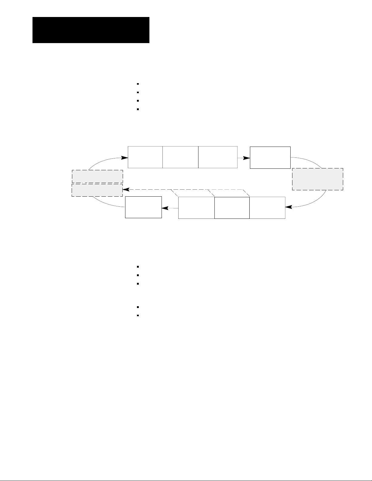
Figure 1.1
Operation of a T
Inject
Injection Pack Hold
Transition to
Pack or Hold
Post- PreDecompression Decompression
ypical Machine Cycle
Plastication
(Reload)
Page 15
Chapter 1
Overview of Inject and Clamp Mode
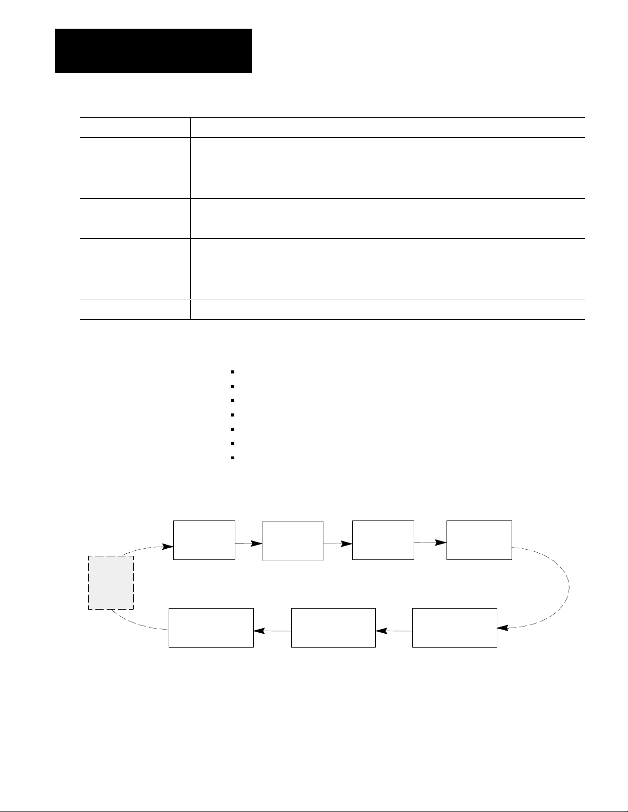
Injection Phase
You can vary the velocity of the ram (screw), or the pressure driving it, so
the leading edge of the melt moves through the mold cavity at the desired
speed. The pattern of velocity or pressure variation during injection is
called the injection profile. The QDC module lets you chose from four
different injection profiles:
velocity vs. position
pressure-limited velocity vs. position
pressure vs. position
pressure vs. time
Figure 1.2
Example
Injection Profile
11 10 9
Velocity or Pressure
87654321
Position or Time
You enter setpoints to create a profile. You can select from 1 to 11
segments of position or time. Segment numbers represent the order of
operation. By convention the ram (screw) injects plastic by moving from
right to left.
With this Profile: You Control Injection: With up to 11 Segments
Velocity vs. Position Speed Length of the shot
Pressurelimited1
Velocity vs. position
Speed with a
maximum pressure
Distributed over the:
Length of the shot
Pressure vs. Position Pressure Length of the shot
Pressure vs. Time Pressure Time for a shot
1
Pressurelimited velocity vs. position profile differs from the velocity vs. position profile as follows:
During any segment, if the pressure exceeds a preset limit, the module switches to PID pressure
control with the pressure limit as the setpoint. Then if velocity exceeds the velocity setpoint, the
module returns to velocity control.
1-3
Page 16
Chapter 1
Overview of Inject and Clamp Mode
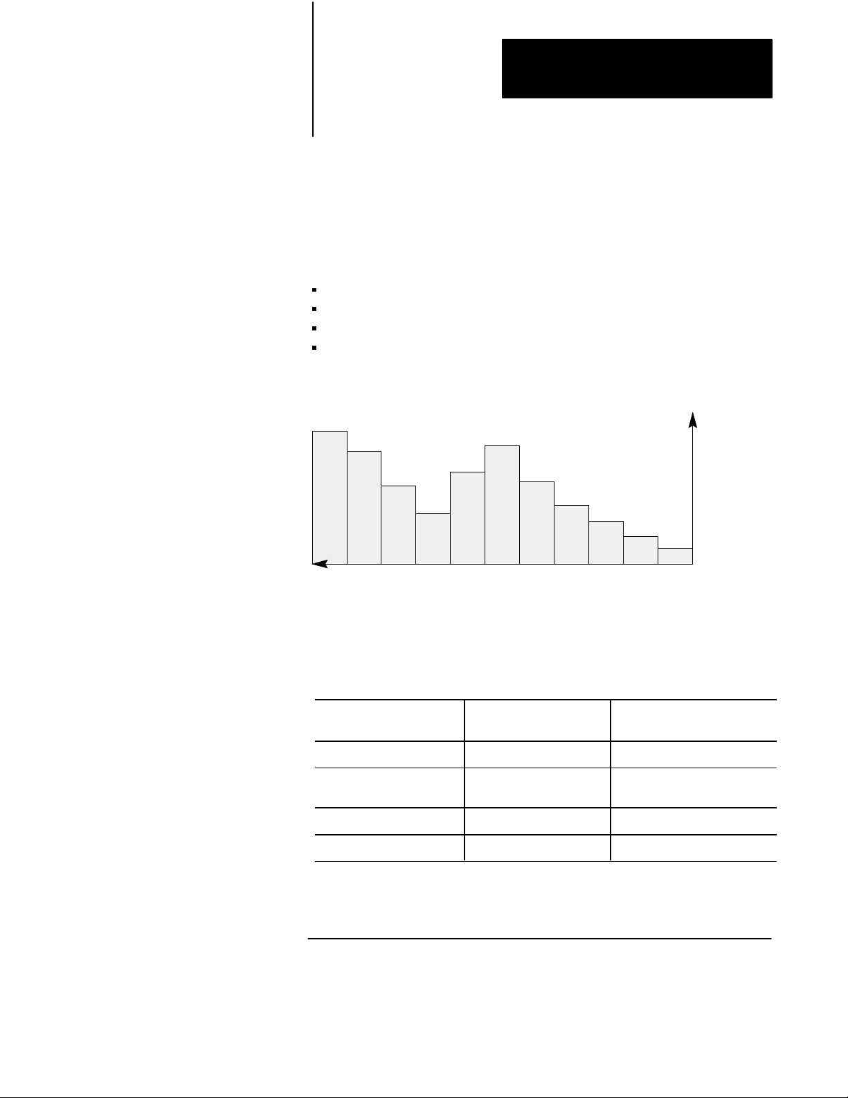
Example Benefits of Profiling an Injection Phase
The injection phase should force the melt through the mold as fast as
possible without flashing the mold or burning the melt at a mold gate.
Here are two examples of how you can achieve this by profiling the
injection phase:
Velocity Example - As the leading edge of the melt enters different mold
cavities, the flow of plastic through the gate should increase or decrease
accordingly to keep the melt front at maximum desired speed without
flashing the mold. This reduces injection time and minimizes surface
stress due to surface cooling. You achieve this by shaping the injection
profile to suit the mold cavity (Figure 1.3).
Mold Cavity
54 3
Flow into mold
Figure 1.3
Velocity
1
2
Example
Gate
Mold
End
Injection Profile
5
4
Position
Sequence of execution
Velocity
23
1
Back
Point
1-4
Page 17
Chapter 1
Overview of Inject and Clamp Mode
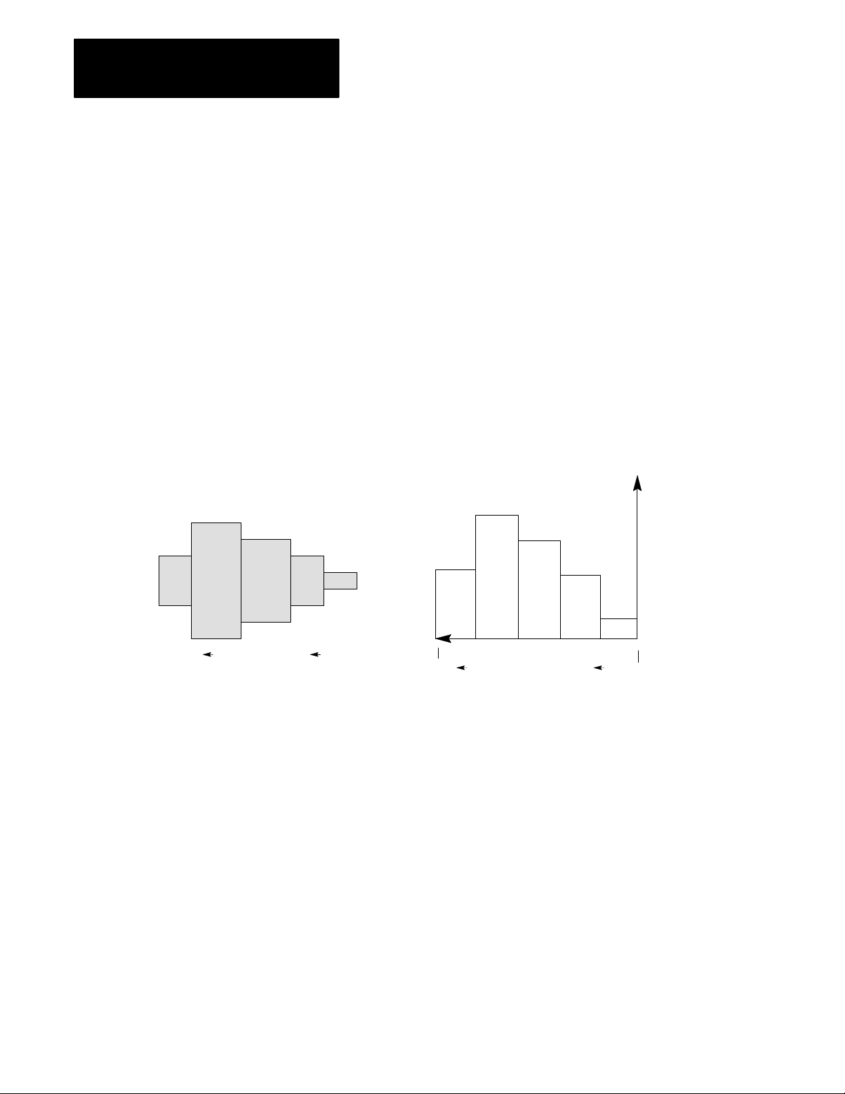
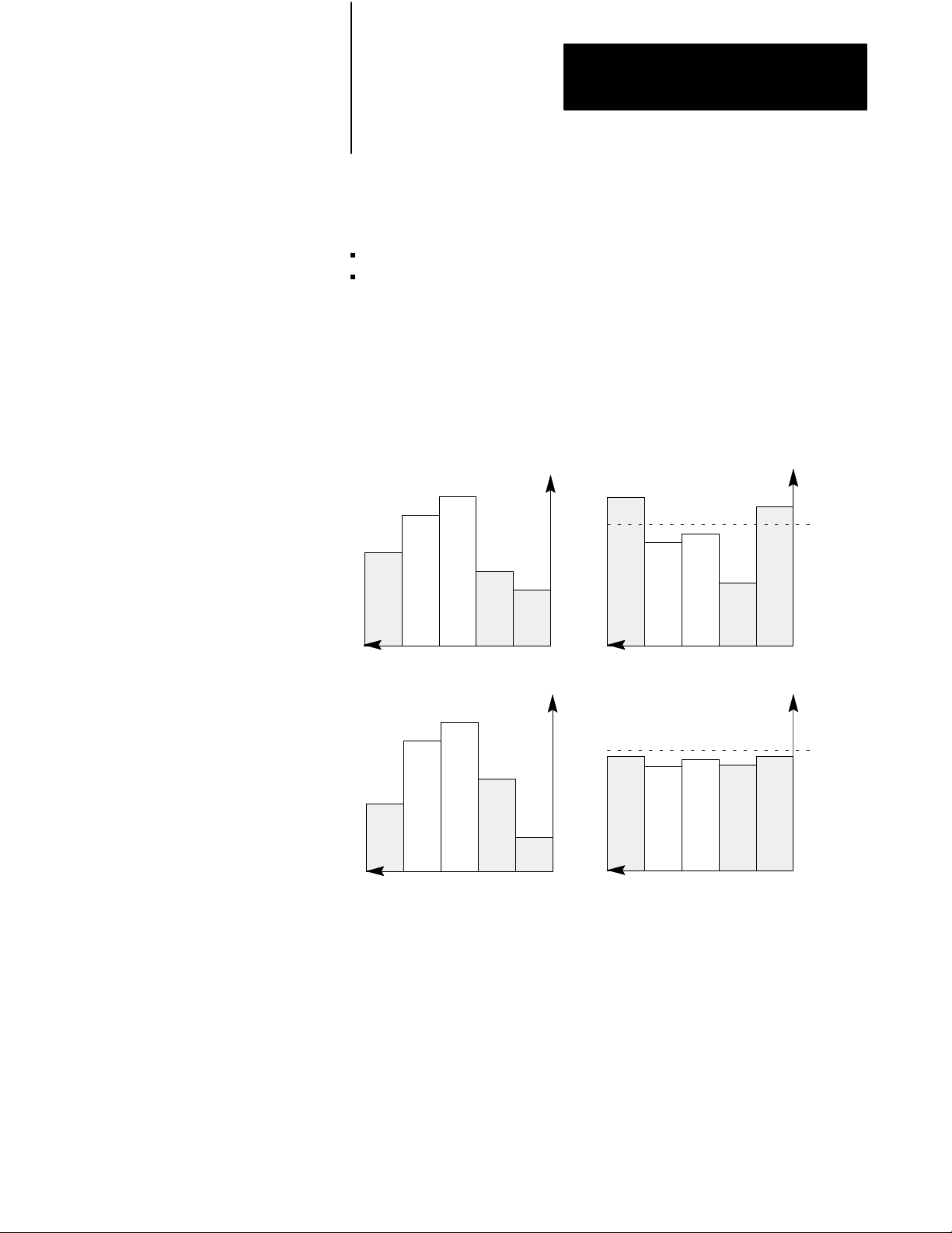
Flash Prevention Example - With a velocity profile (Figure 1.4 part 1),
the pressure may reach a peak and flash the mold at ram (screw) position
segments that correspond to events such as:
the initial surge (2.a)
when the melt front enters a constriction in the mold cavity (2.b)
You can remedy this (part 3) by decreasing the ram (screw) velocity at
segments (3.a) and (3.b) that correspond to flash points. Conversely, you
can boost velocity at segment (3.c) where the resulting pressure is well
below the flash point.
Figure 1.4
Prevention Example
Flash
1. Initial Velocity Profile
Velocity
bca
Position Position
3. Final Velocity Profile
Velocity
b ca
Position
2. Resulting Pressure Profile
ba
4. Resulting Pressure Profile
ba
Position
Flash
Point
Pressure
c
Flash
Point
c
Pressure
Optionally, you may select pressure limited velocity versus position as
your method of injection control. With your pressure limit setpoint just
below the flash point, the module switches over to pressure control prior to
flashing the mold.
1-5
Page 18
Chapter 1
Overview of Inject and Clamp Mode
Injectiontopack Transition
The QDC module ends the injection phase and automatically starts the
pack or hold phase when it detects the first of up to three events occurred:
Ram (screw) position exceeds a preset limit
Ram (screw) pressure exceeds a preset limit
Injection phase elapsed time exceeds a preset limit
You select which of these events you want monitored for transition by
entering the appropriate setpoint, or zero for ignoring the event. You also
may specify the zone of ram (screw) travel over which the QDC module
inhibits or allows a pressure transition.
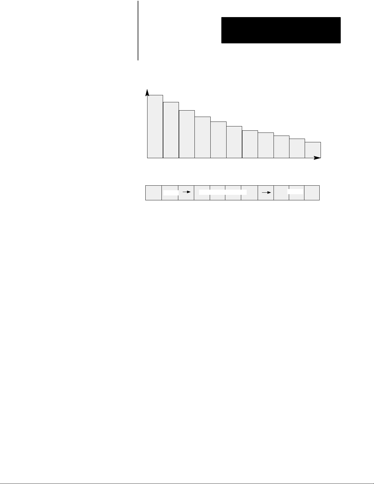
Pack Phase
The QDC module controls the pack phase with a pressure vs. time profile.
You create the profile based on controlling the hydraulic pressure against
the ram (screw). The pressure can be controlled using up to five segments.
By convention, events occur from right to left on the time axis
(Figure 1.5). You determine the pressure setpoints and time durations for
the pack profile based on molding requirements. The pack phase is
optional.
Figure 1.5
Phase Example
Pack
Pressure
4
5
Time
123
1-6
Page 19
Lower density
(last zone filled)
Chapter 1
Overview of Inject and Clamp Mode
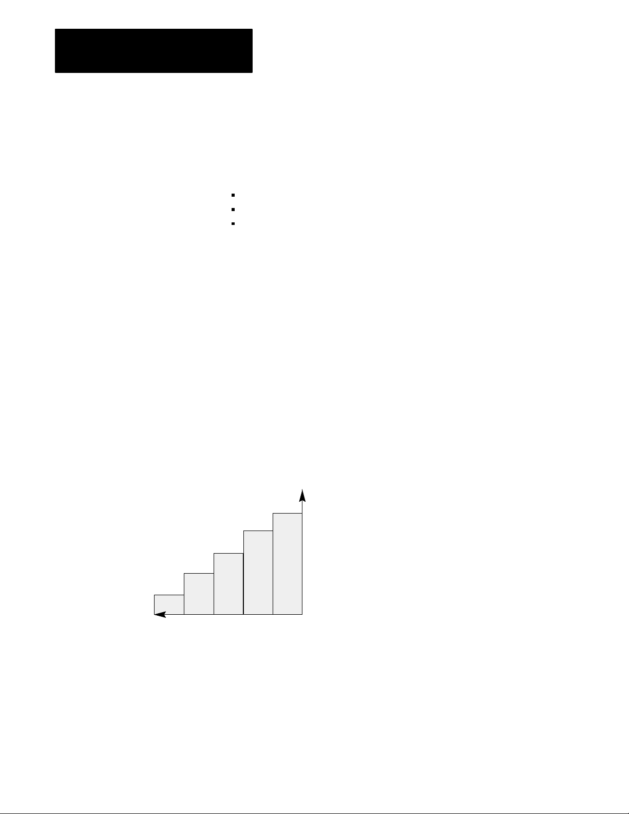
Example Benefit of Profiling the Pack Phase
Molten plastic may cool unevenly in the mold causing variations in density
with the end result of warpage and distortion as shown in Figure 1.6.
Figure 1.6
Uneven
Density in Mold Cavity
Cooling in Pack Phase
Pack Profile
Higher density
(gate zone,
greater pressure)
Gate
Pressure
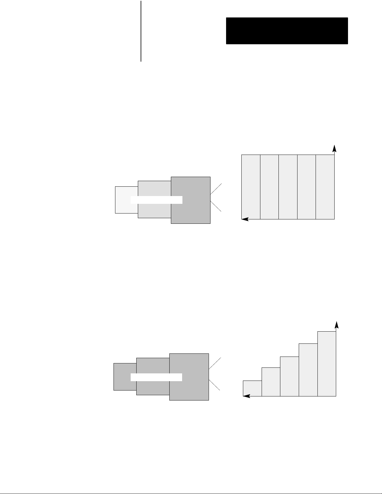
You can remedy this by decreasing the pack pressure with time so plastic
can back out of the mold as shown in Figure 1.7. This is to alleviate
gradations in density as the plastic cools from the low-density end of the
mold (last zone filled) to the high-density end of the mold cavity (gate
zone where pressure is greater).
Figure 1.7
Cooling in Pack Phase
Even
Constant Pressure over entire Mold Cavity
Density in Mold Cavity
Gate
5
5
Pack Profile
Time
Time
234
1
Pressure
234
1
After completing the last segment of the pack phase, the QDC module
automatically starts the hold phase.
1-7
Page 20

Chapter 1
Overview of Inject and Clamp Mode
Hold Phase
The QDC module controls the hold phase with a pressure vs. time profile.
You create the profile based on controlling the hydraulic pressure against
the ram (screw). The pressure can be controlled using up to five segments.
You determine the pressure setpoints and time durations for the hold
profile based on molding requirements.
After completing the last segment of the hold phase, the QDC module
either immediately starts the optional pre-decompression movement, skips
the pre-decompression movement if none is required and immediately
starts the plastication phase, or waits for a command from your PLC-5
program to continue.
Predecompression Movement
You select a length of pullback for the ram (screw) prior to the plastication
phase to separate plastic solidifying in the sprue from molten cushion
remaining in the barrel.
After completing the pre-decompression movement, the QDC module
either immediately starts the plastication phase or waits for a command
from your PLC-5 program to continue.
Plastication Phase
The plastication phase lets you achieve a melt temperature gradient in the
barrel containing the ram (screw). To program the desired temperatures,
you consult backup rate (backpressure) vs. temperature tables. You can
create the profile with up to 11 segments of position or time (figure 1.8).
You chose from two plastication profiles:
Backpressure vs. position
Backpressure vs. time
1-8
Page 21
Chapter 1
Overview of Inject and Clamp Mode
Figure 1.8
Plastication
BackPressure
Mold
End
Phase Example
12 345
Position or Time
hotter
Temperature Gradient
Barrel Containing the Melt
6
7891011
cooler
Back
Point
Example Benefits of Profiling a Plastication Phase
The higher the backpressure during plastication, the slower the backup rate
and higher the resultant temperature of the melt. You can achieve the
desired temperature gradient by lowering ram (screw) backpressure to
accelerate the backup rate and decrease the temperature of the melt along
the length of the barrel.
After completing the last segment of the plastication phase, the QDC
module either immediately starts the post-decompression movement or
waits for a command from your PLC-5 program to continue.
Postdecompression Movement
You select a length of pullback of the ram (screw) after the plastication
phase to guard against drooling molten plastic into the open mold during
ejection. The QDC module notifies your PLC-5 program when the
post-decompression movement is complete.
1-9
Page 22
Chapter 1
Overview of Inject and Clamp Mode
Clamp Control
Ejector retract
Ejector advance
You control clamp operation with these phases:
clamp close
low pressure close
clamp open
open slow
Figure 1.9
Clamp
1st
Close
Open
Slow
Portion of a T
ypical Machine Cycle
2nd
Close
3rd
Open
3rd
Close
2nd
Open
Low Pressure
Close
1st
Open
Clamp Close
Inject
Three separate clamp close profiles may be configured:
first close
second close
third close
You may select from these control modes:
velocity vs. position
pressure vs. position
Use clamp close to move the platen from the fully open position (L) to
some position X at a relatively high velocity or pressure. X is a position
relatively close to the stationary platen yet far enough away to allow
deceleration into low pressure close. This prevents the platens from
coming together at a high velocity (Figure 1.10).
1-10
Page 23
Chapter 1
Overview of Inject and Clamp Mode
Clamp
Cylinder
L
Moving
Platen
Figure 1.10
Example
Clamp Close
0
X
Stationary
Platen
Velocity
1st Close
Profile
2nd
Close
Profile
Position
3rd
Close
Profile
You may start these operations between the three clamp close profiles:
pick up the 3rd plate of a mold (on a floating 3-plate mold) or set cores
program other events for all valves
automatically bridge between profiles, or let ladder logic decide when to
begin the next profile
Each of the clamp close profiles can be subdivided into three position
segments (Figure 1.11). You can change clamp velocity or pressure up to
three times in each profile, or up to nine times for the entire clamp close
phase.
Clamp
Cylinder
L
Moving
Platen
Figure 1.11
Example
Clamp Close Position Segments
Stationary
Platen
0
X
11
1st Close
Profile
Velocity
Segments
2
3
2nd
Profile
Position
2
1
3
Close
2
3rd
Close
Profile
3
Important: You may use as many or as few profiles and/or segments
within profiles as needed for your molding application. If using a single
close fast motion, use the first segment of the 1st close profile. The low
pressure close profile must follow.
After completing the last segment in each profile, the QDC module either
switches immediately to the next programmed segment of the next
programmed profile or waits for a command from your PLC-5 program to
continue.
After completing the last configured close profile, the QDC module either
switches immediately to the first programmed segment of low pressure
close, or waits for a command from your PLC-5 program to continue.
1-11
Page 24
Chapter 1
Overview of Inject and Clamp Mode
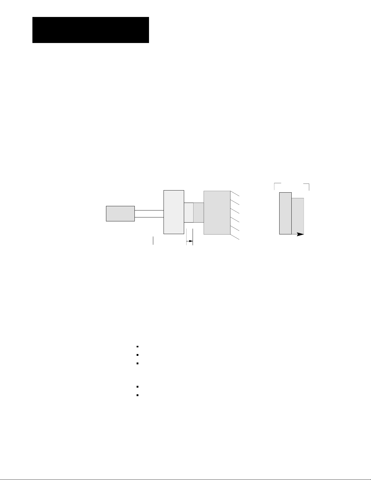
Low Pressure Close
Use the low pressure close profile to decelerate closing motion to guard
against damaging the mold halves and detect for part obstructions. The
pressure setpoint(s) that you select to control low pressure close should
prohibit the mold from fully closing if there is an obstruction. Up to two
low pressure close profile segments may be used (Figure 1.12).
You will use pressure vs. position for low pressure close.
Clamp
Cylinder
Figure 1.12
Example
Low Pressure Close
Moving
Platen
L
0
X
Stationary
Platen
Low Pressure Close
Segments
1
2
Pressure
Position
Important: If you need only one low pressure close segment, configure
the 1st segment of the low pressure close profile.
The QDC notifies your PLC-5 program when this profile is complete and
automatically uses set-output values at the end of low pressure close to
build tonnage (hydraulic machine) or lockup your toggle (toggle machine).
Clamp Open
1-12
You can open the mold fast with three profiles of the clamp open phase:
first open
second open
third open
You may select from these control modes:
velocity vs. position
pressure vs. position
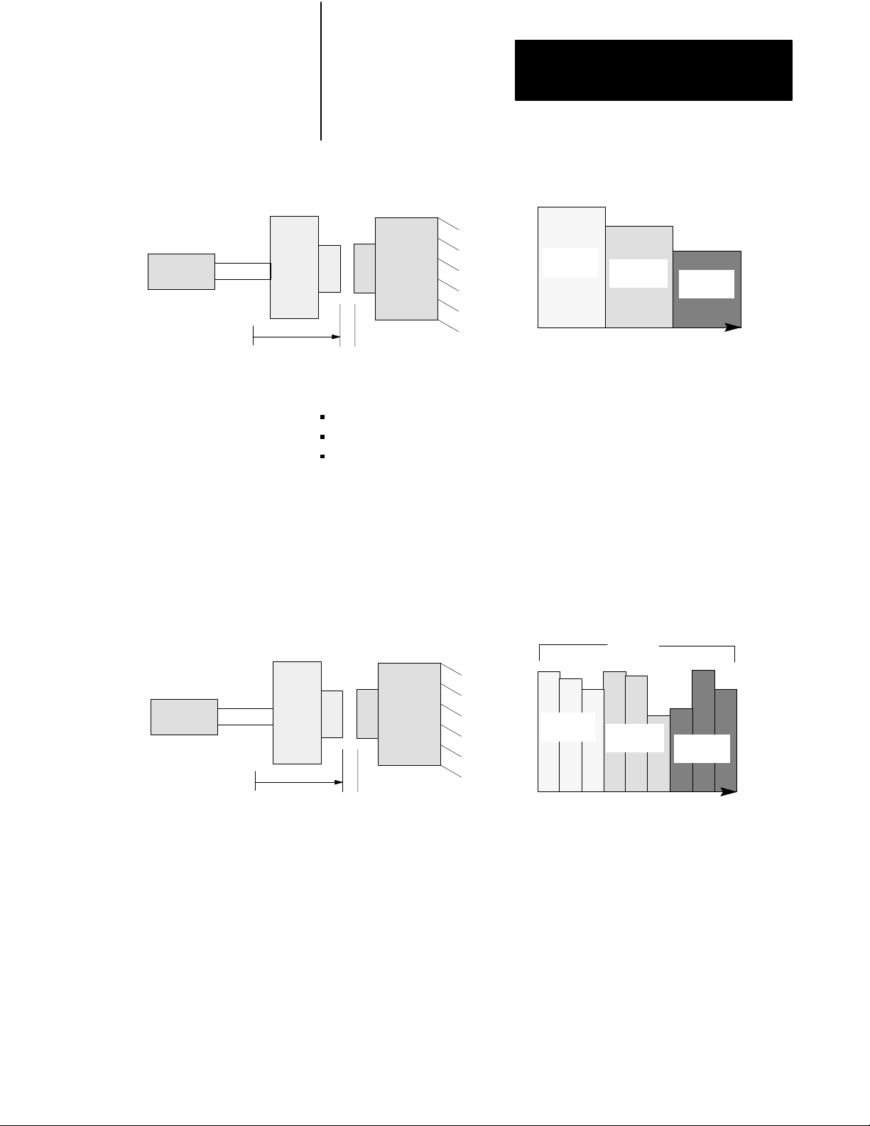
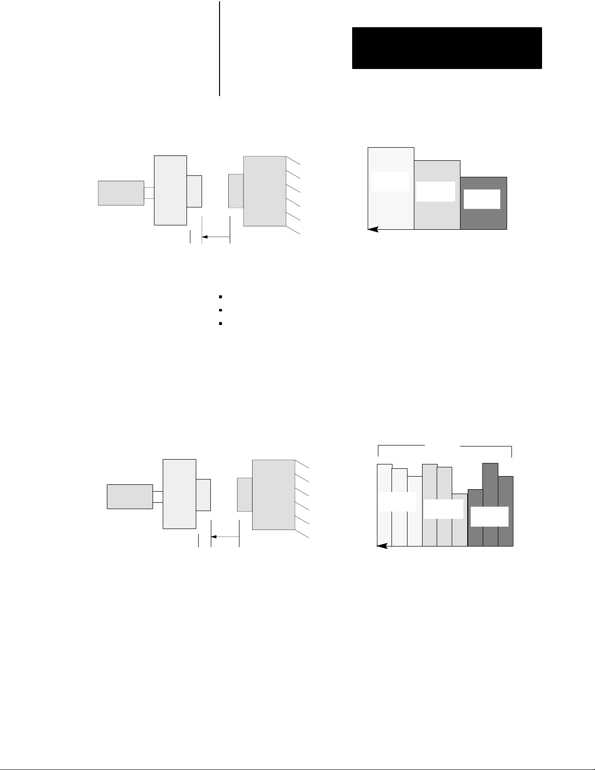
Use clamp open to move the platen from the fully closed position (0) to
some position Y at a relatively high velocity or pressure (Figure 1.13). Y
is close to your fully open position (L), yet far enough away for
deceleration into the open slow profile. This aids positioning accuracy at
the full open position (L).
Page 25
Chapter 1
Overview of Inject and Clamp Mode
Clamp
Cylinder
Moving
Platen
Figure 1.13
Example
L0
Y
Clamp Open
Stationary
Platen
You may start these operations between the three clamp open profiles:
drop the third plate of a mold (on a floating 3-plate mold) or pull cores
program other events for all valves
automatically bridge between profiles, or let ladder logic decide when to
begin the next profile.
Each of the clamp open profiles can be subdivided into three position
segments (Figure 1.14). You can change clamp velocity or pressure up to
three times in each profile, or up to nine times for the entire clamp open
phase.
Velocity
3rd
Open
Profile
2nd
Open
Profile
Position
1st Open
Profile
Clamp
Cylinder
Moving
Platen
Figure 1.14
Example
L0
Y
Clamp Open Position Segments
Stationary
Platen
Velocity
33
3rd Open
Profile
Segments
2
1
2nd Open
Profile
Position
2
1
3
1st Open
Profile
Important: You may use as many or as few profiles and/or segments
within profiles as needed. If using a single open motion, use the first
segment of the 1st open profile. The open slow profile must follow.
After completing the last segment in each profile, the QDC module either
switches immediately to the next programmed segment of the next
programmed profile or waits for a command from your PLC-5 program to
continue.
2
1
1-13
Page 26
Chapter 1
Overview of Inject and Clamp Mode
After completing the last configured open profile, the QDC module either
switches immediately to the first programmed segment of the open slow
profile, or waits for a command from your PLC-5 program to continue.
Open Slow
Use the open slow profile to accurately position the clamp for ejecting the
part(s). You may decelerate clamp motion twice with this profile using up
to two profile segments (Figure 1.15).
You may select from these control modes:
velocity vs. position
pressure vs. position
Figure 1.15
Example
Clamp
Cylinder
Open Slow
Moving
Platen
L0Y
Stationary
Platen
Open Slow
Segments
2
Velocity
Position
Important: If you need only one open slow motion, configure only the 1st
segment of the open slow profile.
1
1-14
Page 27

Chapter
Install the QDC Module
2
Chapter
Objectives
Record I/O Ranges
This chapter guides you through the following procedures:
record I/O ranges
set module jumper plugs
key your I/O chassis
install the QDC module
wire the QDC module
ground your system
plan for E-STOPs and machine interlocks
To match your QDC module to your I/O devices, record the I/O ranges of
your I/O devices on Worksheet 2-A. You will use this information in this
chapter for hardware configuration (setting jumper plugs) and in chapter 4
to configure the module’s inputs and outputs with software.
Circle or check the I/O ranges on Worksheet 2-A. Cross off I/O not used.
Worksheet 2A
I/O Ranges
Record
I/O Connection: Voltage 1: Voltage 2: Current:
Input 1 (Screw position) 0 to 10 Vdc 1 to 5 Vdc 4 to 20 mA
Input 2 (Screw pressure) 0 to 10 Vdc 1 to 5 Vdc 4 to 20 mA
Input 3 (Clamp position) 0 to 10 Vdc 1 to 5 Vdc 4 to 20 mA
Input 4 (Clamp pressure) 0 to 10 Vdc 1 to 5 Vdc 4 to 20 mA
Output 1 10 to 10 Vdc 0 to 10 Vdc 4 to 20 mA
Output 2 10 to 10 Vdc 0 to 10 Vdc 4 to 20 mA
Output 3 10 to 10 Vdc 0 to 10 Vdc 4 to 20 mA
Output 4 10 to 10 Vdc 0 to 10 Vdc 4 to 20 mA
2-1
Page 28

Chapter 2
Install the QDC Module
Set Module Jumper Plugs
Before installing the QDC module, you must select with jumper plugs the
I/O ranges that you recorded on Worksheet 2-A.
Access and Position the Jumpers
Access the jumpers and set them as follows:
ATTENTION: To avoid damage to internal circuits, observe
handling precautions and rid yourself of any electrostatic
charge. Use an anti-static work station when setting jumper
plugs.
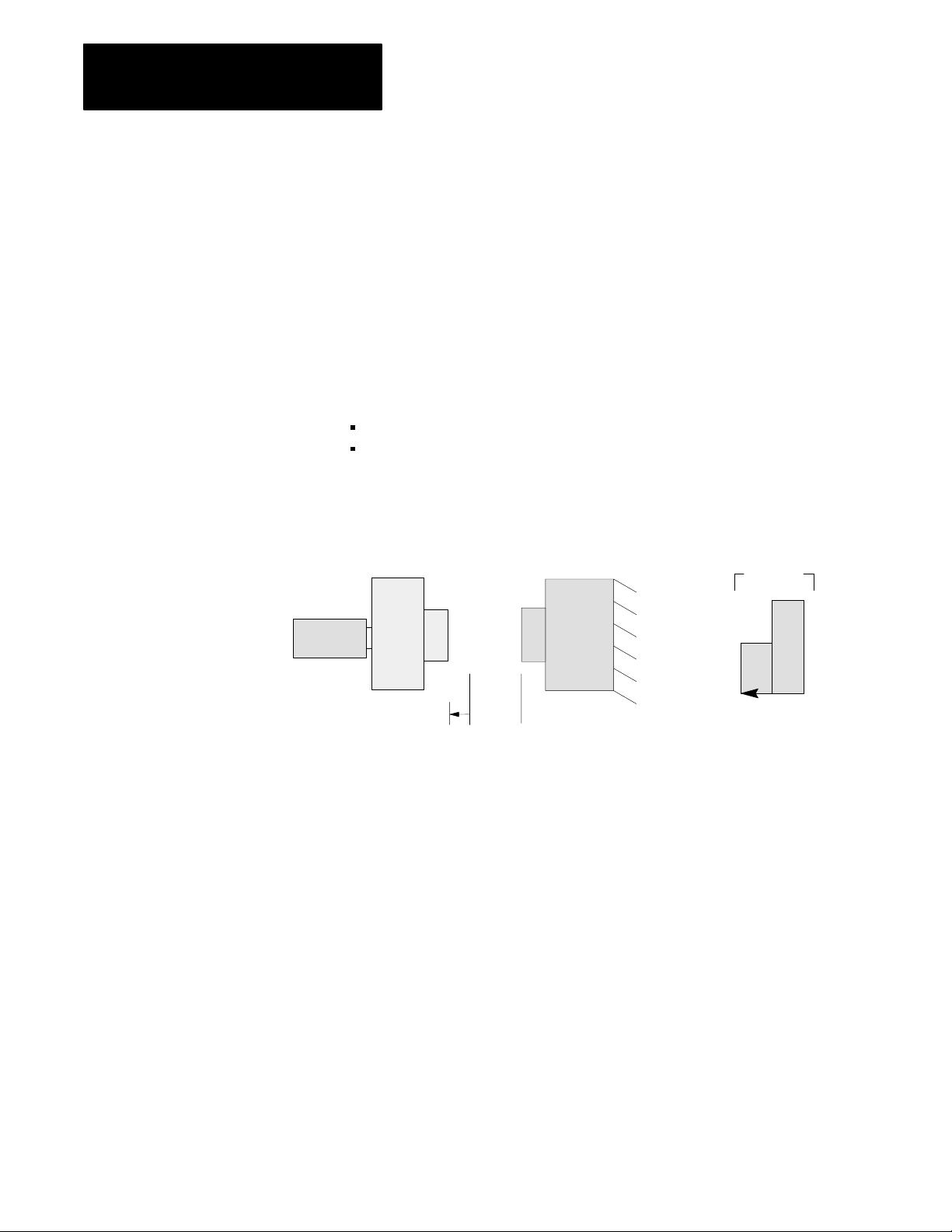
1. Remove the label-side cover plate by removing the four screws.
2. Remove the circuit board from the module housing by removing the
two screws located center-front at the swingarm catch.
3. Carefully turn over the circuit board so it is oriented as in figure 2.1.
Handle it by the edges to avoid touching conductors or components.
4. Use figure 2.1 to locate the jumper plugs.
5. Set the jumper plugs (Table 2.A) using a small needle-nose pliers.
6. After setting the jumper plugs, re-assemble the module.
2-2
Page 29
Chapter 2
Install the QDC Module
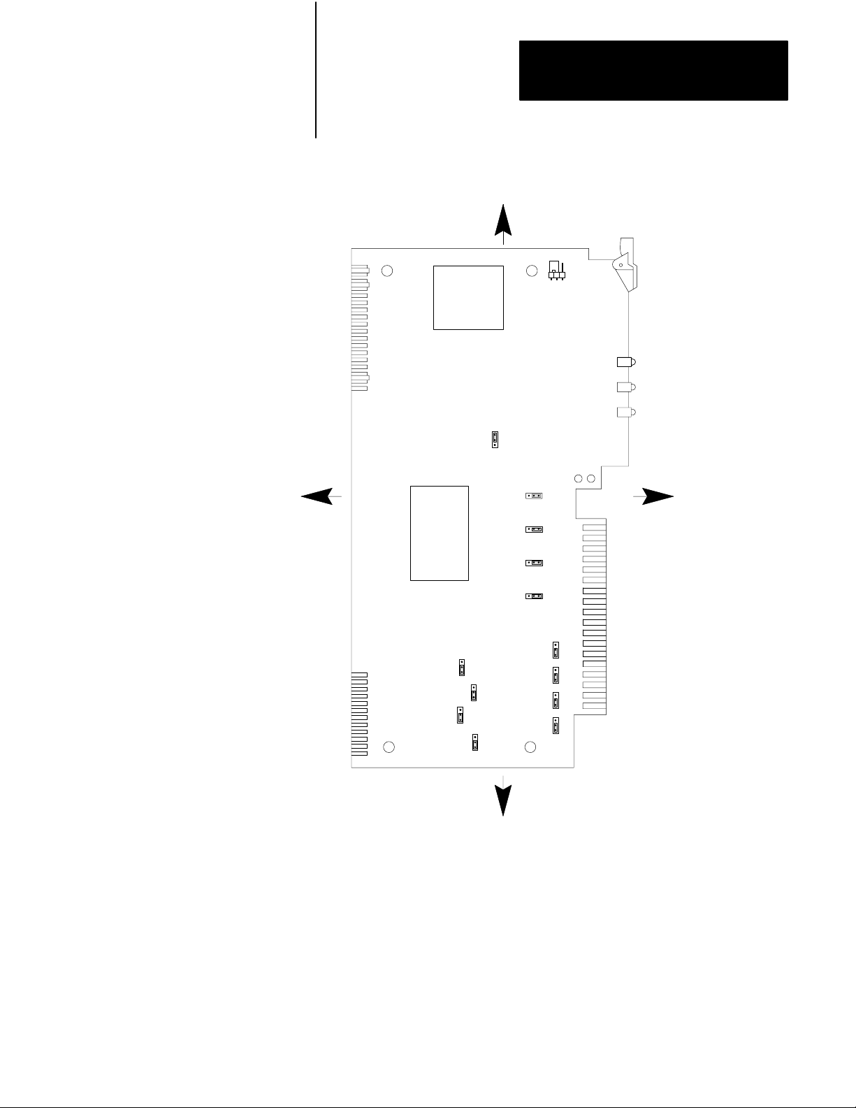
Figure 2.1
Jumper
LEFT
Locations on the QDC Module'
TOP
E5
s Circuit Board
E1
E6
RIGHT
E7
E8
E9
E10
E11
E12
E15
E16
E14
E13
E17
BOTTOM
10908I
Important: We define jumper plug positions as left, right, top, and bottom.
This represents the position of the jumper plug on the 3-pin connector as
relative to the sides of the circuit board shown above.
2-3
Page 30

Chapter 2
Install the QDC Module
Table 2.A
Jumper
Settings
Jumper: Function: Setting:
E1 Run/Calibrate Calibrate = right
E5 I/O Density Standard = top
E6
E7
E8
E9
E10
E14
E13
E17
E11
E12
E15
E16
1
Factory Defaults
Input 1 (Screw position)
Input 2 (Screw pressure)
Input 3 (Clamp position)
Input 4 (Clamp pressure)
Output 1 (Valve 1)
Output 2 (Valve 2)
Output 3 (Valve 3)
Output 4 (Valve 4)
Output 1 (Valve 1)
Output 2 (Valve 2)
Output 3 (Valve 3)
Output 4 (Valve 4)
Run = left
Do not use bottom position
Voltage = right
Current = left
Current = top
Voltage = bottom
-10 to +10 Vdc = top
0 to +10 Vdc or
1
4 to 20mA = bottom
1
1
1
1
Important: If you select current output with jumper plugs E10, E14, E13,
and/or E17, then you must select the 4 to 20mA jumper position with E11,
E12, E15, and/or E16.
ATTENTION: If an output is unconnected, set the jumper
(E11, E12, E15, and/or E16) that corresponds to that output to
0 - 10 Vdc (bottom position). Setting the jumpers for –10 to
+10 Vdc and later configuring the output as “unconnected”
causes the QDC module to output –10 Vdc on that channel
when a system reset occurs and all outputs are forced to 0%
(i.e. 0% output equals –10 Vdc).
2-4
Page 31

Chapter 2
Install the QDC Module
Important: Selecting –10 to +10 Vdc with jumper E11, E12, E15, and/or
E16 sets the QDC module for bi-directional valve operation. The
relationship to percentage output is as follows:
10
8
5
3
0
-3
Output Voltage
-5
-8
-10
0 102030405060708090100
%
Output Requested
Key Your I/O Chassis
Use the plastic keying bands, shipped with each I/O chassis, for keying I/O
slots to accept only one type of module. This is done to prevent the
inadvertent installation of the wrong module into the wrong slot.
The QDC module is slotted in two places on the rear edge of the circuit
board. The position of the keying bands on the backplane connector must
correspond to these slots to allow insertion of the module.
Place keying bands between the following terminal numbers labeled on the
backplane connector of your I/O chassis (see Figure 2.2):
between 20 and 22
between 26 and 28
Figure 2.2
Positions
Keying
2
4
6
8
10
12
14
16
18
20
Keying
Bands
22
24
26
28
30
32
34
36
1771QDC
12676
2-5
Page 32

Chapter 2
Install the QDC Module
Install the QDC Module
To install your QDC module in an I/O chassis, complete the following:
1. Turn off power to the I/O chassis.
ATTENTION: Remove power from the 1771 I/O chassis
backplane and wiring arm before removing or installing a QDC
module.
Failure to remove power from the backplane could cause injury
or equipment damage due to possible unexpected operation.
Failure to remove power from the backplane or wiring arm
could cause module damage, degradation of performance, or
injury.
2. Place the module in the plastic guides on the top and bottom of the
slot that slides the module into position.
Important: Be aware that Pro-Set 600 software expects your Inject and
Clamp QDC module to be placed in slot 0 of your I/O rack 0. If you
choose to install your QDC module in some other slot, some modifications
to your PLC-5 application program will be necessary (refer to your Pro-Set
600 documentation for details).
3. Do not force the module into its backplane connector. Apply firm,
even pressure on the module to seat it properly.
4. Snap the chassis latch over the top of the module to secure it.
5. Connect the wiring arm to the module.
2-6
Page 33

Chapter 2
Install the QDC Module
Wire the QDC Module
+
Customer
PS
–
Screw
Position
Sensor
Screw
Pressure
Sensor
Clamp
Position
Sensor
Clamp
Pressure
Sensor
Use the wiring arm (1771-WF) supplied with the QDC module to wire I/O
devices (Figure 2.3). The wiring arm lets you install or remove the QDC
module from the I/O chassis without rewiring. Wiring arm terminals are
numbered in descending order, from the top down, starting with terminal
18 (Table 2.B).
Figure 2.3
W
iring and Grounding
I/O
+
–
+
–
+
–
+
–
Input 3
Input 4
Input 1
Input 2
–
Customer
PS
18
+
–
+
Amplifier
Valve 1
+
–
+
–
To Valve 1
+
–
Amplifier
Valve 2
Amplifier
Valve 3
+
–
To Valve 2
+
–
17
16
15
14
13
12
11
10
9
8
7
6
5
4
3
2
1
Output 1
Output 2
Output 3
Earth Ground
Wiring Arm
1771WF
Output 4
+
–
Amplifier
Valve 4
To Valve 3
+
–
To Valve 4
10909I
2-7
Page 34

Chapter 2
Install the QDC Module
Table 2.B
T
erminal Designations
I/O
Transducer: I/O Designation: Terminal:
Screw position Input 1 (+)
(-)
Screw pressure Input 2 (+)
(-)
Input common 14
Clamp position Input 3 (+)
(-)
Clamp pressure Input 4 (+)
(-)
Valve 1 Output 1 (+)
Output common
Valve 2 Output 2 (+)
Output common
Valve 3 Output 3 (+)
Output common
Valve 4 Output 4 (+)
Output common
Not used 01
18
17
16
15
13
12
11
10
09
08
07
06
05
04
03
02
ATTENTION: The QDC module has ESD protection to 20kV,
but you can damage the module by accidental application of the
wrong voltage to the I/O terminals. Do not exceed:
This voltage: On these terminals: When in:
+12 Vdc input (18 thru 10) any mode
+12 Vdc output (09 thru 02) voltage mode
+24 Vdc output (09 thru 02) current mode
2-8
Page 35

Chapter 2
Install the QDC Module
Ground and Shield
our I/O Devices
Y
Input Sensor
Analog inputs and outputs are sensitive to electrical noise interference.
Take care to shield them properly.
Guidelines:
Use 22-gage (or larger) twisted-pair cable, 100% shielded with drain
wire, such as Belden 8761. For cable distances over 50 ft, use 18-gage
cable such as Belden 8760.
Ground the cable shield at one end only; generally at the sensor or
amplifier end of the cable, not at the I/O chassis (see Figure 2.4 and
Figure 2.5)
Figure 2.4
Shielding
Differential Inputs
QDC Module Input
18
17
+15V
+
–
Connect the cable shield
and case ground to earth
ground at the Input Sensor
14
No User Connectiions.
For Test Purposes, only.
-15V
Input Module Common
should float
109102
2-9
Page 36

Chapter 2
Install the QDC Module
Figure 2.5
Shielding
QDC Module Output
Singleended Outputs
Customer Valve Amplifier
+
–
9
8
Connect the cable shield
to earth ground at the valve
amplifier
Input
Ground
Chassis Ground
17182
ground the cable shields to a low-impedance earth ground of less than
1/8 ohm
do not connect any ground to input common (terminal 14) except as
specified below under Grounding Exceptions
place high-voltage class A wiring and low-voltage class B wiring in
separate grounded conduits
in parallel runs, separate the class A and B conduit by at least 1 foot
where conduit runs must cross, cross them at right angles
For additional grounding recommendations, refer to the Allen-Bradley
Programmable Controller Wiring and Grounding Guidelines (publication
1770-4.1).
Exceptions
If you experience unacceptable electrical noise interference, then try one or
both of the following alternative grounding connections:
connect the input cable shield to input common (terminal 14) after
disconnecting the shield from the transducer
connect the output cable shield to output common (terminal 8, 6, 4,
and/or 2) after disconnecting it from the valve amplifier
2-10
Page 37

Chapter 2
Install the QDC Module
Plan for ESTOPs and
Machine Interlocks
You must consider the installation of Emergency Stop switches and
machine interlocks when you:
design your system
assemble mechanical/hydraulic components
wire system components
develop system ladder logic
ATTENTION: The Electrical Standard for Industrial
Machinery (NFPA 79-1987) requires an emergency stop that,
when actuated, de-energizes all electrical power circuits which
provide electrical energy to sustain machine motion.
Maintained contact “Emergency Stop” push buttons are
recommended.
ATTENTION: The American National Standard for Plastics
Machinery — Horizontal Injection Molding Machines — for
Construction, Care, and Use (ANSI B151.1-1984) requires
hydraulic, mechanical, and electrical interlocks to prevent
inadvertent clamp closing with a safety gate in an open position.
In addition, we strongly recommend that the electrical
interlocks consist of redundant devices and that the control
circuit be so arranged that malfunction or improper sequencing
of either redundant device prevents further operation of the
machine.
ATTENTION: NEMA Standards Publication ICS1.1, Safety
guidelines for the Application, Installation, and Maintenance of
Solid State Control recommends that the emergency stop and
safety gate electrical interlocks should directly control their
appropriate functions through an electromechanical device
independent of the solid state logic.
The next page shows an illustration of a typical grounded PLC-5 power
distribution circuit. For ungrounded systems or for more information on
grounding and wiring guidelines, refer to Allen-Bradley Programmable
Controller Wiring and Grounding Guidelines (publication 1770-4.1).
2-11
Page 38

Chapter 2
Install the QDC Module
Disconnect
Figure 2.6
PLC5 Power Distribution with Interlocks
Typical
L1
L2
L3
Incoming
AC
Use any number
of E-Stop switches
in Series
CRM
Input
Device
1FU
2FU
3FU
H
H
1
H
H
3
4
2
Step-down
Transformer
4
FUSE
X
X
1
2
Start
CRM
I/O Chassis
Power Supply
1
LN
GND
3
** See WARNING for Interlock Wiring Instructions **
2
Output
Input
Device
Module
Wiring
Arm
Output
Module
Wiring
Arm
CRM
1
Back-Panel
Ground Bus
5
L1
L2
L3
To Motor
Starters
Equipment
Grounding
Conductors
User DC
CRM
To DC I/O
Devices
Enclosure
Wall
Grounding Electrode
Conductor to
Grounding Electrode
System
Connect
When
Applicable
Supply
+–
1
To minimize EMI generation, you should connect a suppression network: for 120V AC, use Allen-Bradley
cat. no. 700-N24; for 220/240V AC, use cat. no. 599-KA04.
2
To minimize EMI generation, you should connect a suppression network: for 120V AC, use Allen-Bradley
cat. no. 599-K04; for 220/240V AC, use cat. no. 599-KA04.
3
For a power supply with a groundable chassis, this represents connection to the chassis only. For a power supply
without a groundable chassis, this represents connection to both the chassis and the GND terminal.
In many applications, a second transformer provides power to the input circuits and power supplies for isolation from the
4
output circuits.
Reference the current NEC code and ANSI B151.1 for additional wiring guidelines.
•
5
To minimize EMI generation, suppression networks should be connected across coils of electromagnetic devices.
•
2-12
10907I
Page 39

Chapter
3
Configure the QDC Module's I/O
Chapter
Objectives
Your QDC module needs to know the characteristics of your ram (screw)
and clamp sensors. In this chapter, we describe how to determine these
characteristics and download them to the QDC module. Topics include:
signal ranges from pressure and position sensors
minimum and maximum sensor signals corresponding to
minimum and maximum pressures and positions
alarm values and travel limits
We describe how to configure the QDC module in these sections:
select module parameters and I/O ranges
determine initial sensor configuration values
download configuration values to the QDC module
use the set-output operation to move the ram (screw) and clamp
complete your sensor configuration
use optional sensor configurations
Important: You must properly configure the QDC module using
procedures in this chapter before attempting further configurations.
Important: If you have not already done so, install Pro-Set 600 software.
The procedures in this and the next several chapters assume that you have.
Select Module Parameters
and I/O Ranges
You select module parameters and I/O ranges by setting configuration bits
in control words. First, determine and write down correct settings using
Worksheet 3-A through Worksheet 3-C as follows:
To Configure: In Control Word: Starting At Addr: Use this Worksheet:
Module Parameters MCC02 B34/528 Worksheet 3A
Input Range MCC03 B34/544 Worksheet 3B
Output Range MCC04 B34/560 Worksheet 3C
3-1
Page 40
Chapter 3
Configure the QDC Module's I/O
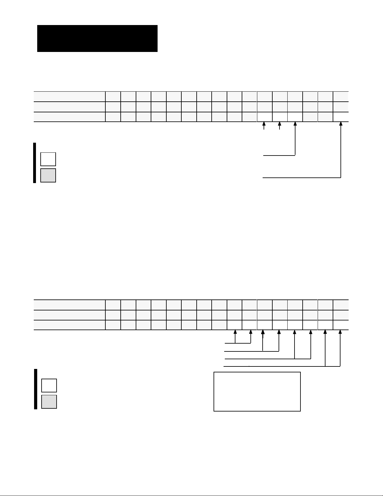
Worksheet 3A
Select Module Parameters
Control W
ProSet 600 Addr. B34/bit
ord MCC02Bxx
15 14 13 12
11 10
09 08 07 06 05 04 03 02 01 00
543 542 541 540 539 538 537 536 535 534 533 532 531 530 529 528
Value 0 0 0 0 0 0 0 0 0 0 0 1 1 0 0
Select
System Operation with bits 05 and 04
Inject and Clamp 0 1
Code:
0
or 1
Your value
Required initial value
loaded by ProSet 600
Select Singleunit Operation with bit 03 = 1
(0 generates a programming error)
Select English = 0 or
metric = 1 with bit 00
Example: If you select Inject and Clamp operation with English units:
MCC02 = 00000000 00011000
Select I/O Ranges for your Sensors
Next, configure the QDC module’s I/O ranges to match the machine
sensors and valves. Refer to Worksheet 2-A from chapter 2 which you
filled out when setting the QDC module’s jumpers. Apply this information
to Worksheet 3-B for input ranges and Worksheet 3-C for output ranges.
Worksheet 3B
Input Ranges for your Sensors
Select
Control W
ProSet 600 Addr. B34/bit
ord MCC03Bxx
15 14 13 12
11 10
09 08 07 06 05 04 03 02 01 00
559 558 557 556 555 554 553 552 551 550 549 548 547 546 545 544
Value 1 1 1 1 1 1 1 1
Select Input 4 (Clamp Pressure) Range with bits 07, 06
Select Input 3 (Clamp Position) Range with bits 05, 04
Select Input 2 (Screw Pressure) Range with bits 03, 02
Select Input 1 (Screw Position) Range with bits 01, 00
Code:
Your value
0
or 1
Required initial value
loaded by ProSet 600
Example: If you select an input range of 4-20 mA for all four inputs:
MCC03 = 11111111 10101010.
Important: Software input selections must match the jumper settings for
each respective input.
Input Range
0 - 10V dc 0 0
1 - 5V dc 0 1
4 - 20 mA 1 0
Not connected 1 1
3-2
Page 41

Worksheet 3C
Select Output Ranges for your V
Chapter 3
Configure the QDC Module's I/O
alves
Control W
ProSet 600 Addr. B34/bit
Value 1 1 1 1 1 1 1 1
Code:
0
or 1
ord MCC04Bxx
Your value
Required initial value
loaded by ProSet 600
15 14 13 12
575 574 573 572 571 570 569 568 567 566 565 564 563 562 561 560
Select Output 4 Range with bits 07, 06
Select Output 3 Range with bits 05, 04
Select Output 2 Range with bits 03, 02
Select
Output 1 Range with bits 01, 00
11 10
09 08 07 06 05 04 03 02 01 00
Example: If you select 0-10V dc for all four output ranges:
MCC04 = 11111111 01010101.
Important: Software output selections must match the jumper settings for
each respective output.
Determine
Initial
Sensorconfiguration Values
To determine initial sensor configuration values, refer to Table 3.A, and
specifications that accompanied your sensors, valves, and cylinders. Write
down applicable values on Worksheet 3-D.
Output Range
-10 to +10V dc 0 0
0 to +10V dc 0 1
4 to 20 mA 1 0
Not connected 1 1
Important: You must enter floating-point numbers and percentages as
integers, so we recommend that you write them in Worksheet 3-D in the
following format: Use an assumed decimal point position that depends on
the range value. For example:
If the Range is: And You Want to
Enter this Value:
0 099.99% 75% 07500
0 99.99 inch 7.32 inch 00732
0 0999.9 mm 432.6 mm 4326
4.00 020.00 mA 16 mA 01600
0 010.00V dc 5.6V dc 00560
0 009.99 sec 0.47 sec 00047
0 09999 psi 321 psi 00321
0 0999.9 Bar 222 Bar 2220
Use this
Format:
3-3
Page 42

Chapter 3
Configure the QDC Module's I/O
Table 3.A
Determine
Category: If your: Then Use a Value Equal to:
Minimum Position
(Lines 1 and 9)
Maximum Position
(Lines 2 and 10)
Analog Signal @ Min Position sensor is forwardacting low end of your selected range
(Lines 3 and 11) sensor is reverseacting high end of your selected range
Analog Signal @ Max Position sensor is forwardacting high end of your selected range
(Lines 4 and 12) sensor is reverseacting low end of your selected range
Minimum Pressure
(Lines 5 and 13)
Maximum Pressure
(Lines 6 and 14)
Analog Signal @ Min Pressure sensors are forwardacting low end of your selected range
(Lines 7 and 15) sensors are reverseacting high end of your selected range
Initial Sensorconfiguration V
N/A zero
ram
(screw) is fully extended to the
mold end (ram bottom), and the
mold closed position is zero.
N/A minimum range value specified by the
N/A maximum range value specified by
alues for W
orksheet 3D
maximum range value specified by the
manufacturer (full travel of the sensor
manufacturer
manufacturer
Analog Signal @ Max Pressure sensors are forwardacting high end of your selected range
(Lines 8 and 16) sensors are reverseacting low end of your selected range
3-4
Page 43

Worksheet 3D
Determine Initial Sensorconfiguration V
Enter Your Initial Values Here
Chapter 3
Configure the QDC Module's I/O
alues
Input Line Control Word ProSet
600 Addr
. Value Description Units
1 1 MCC09 N40:5 0 Minimum Screw Position Screw Axis Measured from zero
2 MCC10 N40:6 Maximum Screw Position Screw Axis Measured from zero
3 MCC11 N40:7 Analog Signal @ Min Screw Position Input Signal Range
4 MCC12 N40:8 Analog Signal @ Max Screw Position Input Signal Range
2 5 MCC17 N40:13 0 Minimum Screw Pressure Screw Pressure
6 MCC18 N40:14 Maximum Screw Pressure Screw Pressure
7 MCC19 N40:15 Analog Signal @ Min Screw Pressure Input Signal Range
8 MCC20 N40:16 Analog Signal @ Max Screw Pressure Input Signal Range
2
2
3
3
2
2
3 9 MCC23 N40:19 0 Minimum Clamp Position Clamp Axis Measured from zero
10 MCC24 N40:20 Maximum Clamp Position Clamp Axis Measured from zero
11 MCC25 N40:21 Analog Signal @ Min Clamp Position Input Signal Range
12 MCC26 N40.22 Analog Signal @ Max Clamp Position Input Signal Range
4 13 MCC31 N40:27 0 Minimum Clamp Pressure Clamp Pressure
14 MCC32 N40:28 Maximum Clamp Pressure Clamp Pressure
15 MCC33 N40:29 Analog Signal @ Min Clamp Pressure Input Signal Range
16 MCC34 N40:30 Analog Signal @ Max Clamp Pressure Input Signal Range
1
Incremental Distance
00.00
to 99.99in
000.0 to 999.9mm
2
Input Signal Range
00.00 to 10.00VDC or
01.00 to 05.00VDC or
04.00 to 20.00MADC
3
Pressure
0000 to 9999 PSI
000.0 to 999.9 Bar
2
2
3
3
2
2
1
1
1
1
Download MCC Values
to the QDC Module
Use this download procedure now and later in this chapter. The procedure
requires you to complete the following general steps:
enter MCC values into the PLC-5 data table
download them to the QDC module (PLC-5 processor in run mode)
correct any data entry (programming) errors
Next we describe the general steps:
Enter MCC Values into Your PLC5 Data Table
With your programming terminal, enter values from Worksheet 3-A thru
Worksheet 3-D into your PLC-5 data table as follows:
1. Switch the PLC-5 processor to program mode.
2. Display your PLC-5 data table.
3. Locate the data file for storing the MCC block. PLC-5 data table
word addresses are listed on the worksheets.
3-5
Page 44

Chapter 3
Configure the QDC Module's I/O
4. Enter the value for each word and bit.
When you enter bit selections in words prefixed with file identifier B
(example: B34), the PLC-5 processor automatically switches the radix to
binary format so you can conveniently enter binary data.
Download MCC Values to the QDC Module
To download the MCC block to the QDC module, switch the PLC-5
processor from program to run mode. Pro-Set 600 software downloads the
MCC block to the QDC module for you.
Important: You can verify that the MCC block was successfully downloaded or that you made a data entry (programming) error by evaluating
the following words that Pro-Set 600 software continuously reports to the
PLC-5 processor.
If: And: Then:
SYS01B08 = 1
(B34/8)
SYS19B00 = 1
(B34/288)
N/A QDC module accepted a valid MCC.
SYS61 = 1
(ID code for MCC block
stored in N40:213)
You made a programming error in MCC.
Read the error code in SYS62 (N40:214) , and
look up the error in Section 2 of QDC Module
Reference Manual, publication 17716.5.88.
Important: Pro-Set 600 software downloads all command blocks when
your PLC-5 processor enters run mode after a valid MCC block is
accepted. All programming errors reported in SYS62 (N40:214) are
referenced to the MCC block until SYS01-B08 = 1.
Correct Any Dataentry (Programming) Errors in MCC
Upon receipt of the MCC block, the QDC module tests data for data-entry
errors, such as a value out of range. When it detects an error, the QDC
module halts operation until you correct the error. For a complete list of
error codes to help you correct a programming error, refer to Section 2 of
the Plastic Molding Module Reference Manual, publication 1771-6.5.88.
You must correct errors by entering the changed configuration values into
your PLC-5 data table and downloading the new values to the QDC
module as outlined above. Pro-Set 600 software continues to attempt to
download the MCC block to the QDC module until an MCC block is
accepted and the QDC module returns SYS01-B08 = 1.
3-6
Important: The QDC module must receive a valid MCC block before you
can download additional blocks.
Page 45

Chapter 3
Configure the QDC Module's I/O
Use Setoutput Operation to
Move the Ram (screw) and
Clamp
To finish configuring the QDC module, you actuate the ram (screw) and
clamp with the QDC module’s set-output operation that applies percentage
values to your QDC module’s outputs to move the ram (screw) or clamp in
a controllable fashion. To do this, you apply %-output signals to all
module outputs so you can move the actuator over its intended range.
Sensor spanning values can then be refined per the actual values monitored
by the QDC module.
ATTENTION: Do not rely on pressure valves connected to the
QDC module for pressure relief. Use them only for pressure
control below the setting of the system pressure-relief valve.
ATTENTION: A value of zero in set-output words N40:121 N40:124 does not necessarily correspond to zero pressure or
flow. If you have configured jumper E11, E12, E15, and/or E16
for bi-directional valve operation, an output of 0% gives
–10 vdc, 50% gives 0 vdc (see chart). Amplifier electronics or
spool-null offsets may also allow pressure or flow at zero volts
signal input. Consult your valve and amplifier specifications.
10
8
5
3
0
-3
Output Voltage
-5
-8
-10
0 102030405060708090100
%
Output Requested
ATTENTION: As soon as you enable set-output operation, the
QDC module’s outputs drive the connected valves according to
the values you entered into DYC09-12 (N40:121-124). Be sure
these values RESULT IN NO MOVEMENT until you adjust
them one-at-a-time with your programming terminal in the
procedures that follow.
3-7
Page 46

Chapter 3
Configure the QDC Module's I/O
Actuate the Ram (screw) and Clamp with Setoutput Operation
1. Enter values that result in no motion in these DYC words:
Output: In Data Word: At ProSet 600
Address:
1 DYC09 N40:121
2 DYC10 N40:122
3 DYC11 N40:123
4 DYC12 N40:124
2. Enable set-output operation by entering a 1 in DYC01-B08
(B34/392). The QDC module sets outputs 1 - 4 to percentage values
that you entered in DYC09-12 respectively.
Complete your Sensor
Configuration
3. With your programming terminal, slowly change the %-output value
of one output as you observe the corresponding movement.
Important: The DYC is constantly transferred to the QDC module by
Pro-Set 600 software, so changes you make to %-output values are
immediately implemented.
Complete the procedure for configuring the QDC module to match its
sensors by spanning them over their intended range with the machine in
operation. Here we describe how you determine:
clamp position sensor values
clamp pressure sensor values
screw position sensor values
screw pressure sensor values
In the procedures that follow, measure and record:
minimum and maximum positions
corresponding signal values
minimum and maximum pressures
corresponding signal values
After determining these values from the procedures, write them down on
Worksheet 3-E.
3-8
Important: You must complete this configuration before proceeding to
any other chapters on module configuration.
Page 47

Worksheet 3E
Final Sensorconfiguration V
Chapter 3
Configure the QDC Module's I/O
alues
Enter Your Final V
alues Here
Input Line Control Word ProSet 600 Addr. Value Description Units
1 1 MCC09 N40:5 0 Minimum Screw Position Screw Axis Measured from zero
2 MCC10 N40:6 Maximum Screw Position Screw Axis Measured from zero
3 MCC11 N40:7 Analog Signal @ Min Screw Position Input Signal Range
4 MCC12 N40:8 Analog Signal @ Max Screw Position Input Signal Range
2 5 MCC17 N40:13 0 Minimum Screw Pressure Screw Pressure
6 MCC18 N40:14 Maximum Screw Pressure Screw Pressure
7 MCC19 N40:15 Analog Signal @ Min Screw Pressure Input Signal Range
8 MCC20 N40:16 Analog Signal @ Max Screw Pressure Input Signal Range
2
2
3
3
2
2
3 9 MCC23 N40:19 0 Minimum Clamp Position Clamp Axis Measured from zero
10 MCC24 N40:20 Maximum Clamp Position Clamp Axis Measured from zero
11 MCC25 N40:21 Analog Signal @ Min Clamp Position Input Signal Range
12 MCC26 N40:22 Analog Signal @ Max Clamp Position Input Signal Range
4 13 MCC31 N40:27 0 Minimum Clamp Pressure Clamp Pressure
14 MCC32 N40:28 Maximum Clamp Pressure Clamp Pressure
15 MCC33 N40:29 Analog Signal @ Min Clamp Pressure Input Signal Range
16 MCC34 N40:30 Analog Signal @ Max Clamp Pressure Input Signal Range
1
Incremental Distance
00.00
to 99.99in
000.0 to 999.9mm
2
Input Signal Range
00.00 to 10.00VDC or
01.00 to 05.00VDC or
04.00 to 20.00MADC
3
Pressure
0000 to 9999 PSI
000.0 to 999.9 Bar
2
2
3
3
2
2
1
1
1
1
Determine Values for Ram (Screw) Position Sensor
ATTENTION: Incorrect values entered in DYC09-12 may
result in rapid ram (screw) motion and potential damage to your
barrel and seals of your injection cylinder.
To complete the configuration for your ram (screw) position sensor, do the
following and enter the results on Worksheet 3-E:
Important: If your position sensor has zero and span potentiometers for
setting the zero reference and linear resolution, set them in this procedure.
1. Move the ram (screw) forward until it reaches its mechanical stop at
the nozzle end. This is the zero position.
2. Remove ram (screw) pressure and/or flow to stop movement.
3-9
Page 48

Chapter 3
Configure the QDC Module's I/O
3. Record this position value (normally 0000) on line 1 for MCC09 on
Worksheet 3-E.
4. With your programming terminal, read the signal level returned in
SYS33 (N40:185) from your position sensor. You may wish to zero
your position sensor at this time.
5. Record this value on line 3 for MCC11 (should be at minimum signal
if you zeroed your position sensor in step 4).
6. Move the ram (screw) backward to the backpoint mechanical stop.
7. Remove ram (screw) pressure and/or flow to stop movement.
8. Measure the distance travelled.
9. Record this distance on line 2 for MCC10.
10. With your programming terminal, read the signal level returned in
SYS33 (N40:185) from your positioning sensor. You may wish to
span your position sensor at this time.
11. Record this value on line 4 for MCC12.
You may now download your adjusted values to the QDC module using
the MCC download procedure presented earlier in this chapter.
Determine Values for the Clamp Position Sensor
Important: Use the following procedure and subsequent set-up
information for each different mold used on a hydraulic machine. On a
toggle clamp (with die height adjust), complete it only once.
ATTENTION: Incorrect values entered in DYC09-12 may
result in rapid clamp motion and potential damage to your mold
or cylinder seals. We strongly recommend using a “dummy”
mold on hydraulic machines and no mold on toggle machines.
Important: If your position sensor has zero and span potentiometers to set
the zero reference and linear resolution, do so during this procedure.
3-10
1. Move the clamp forward until it reaches its mechanical close stop.
This is the zero position.
2. Remove clamp pressure and/or flow to stop clamp movement.
Page 49

Chapter 3
Configure the QDC Module's I/O
3. Record this position value (usually 0000) on line 9 for MCC23 on
Worksheet 3-E.
4. With your programming terminal, read the signal level returned in
SYS35 (N40:187) from your position sensor. You may wish to zero
your position sensor at this time.
5. Record this value on line 11 for MCC25 (should be at minimum
signal if you zeroed your position sensor in step 4).
6. Move the clamp backward to the mechanical open stop.
7. Remove clamp pressure and/or flow to stop clamp movement.
8. Measure the distance travelled.
9. Record this distance on line 10 for MCC24.
10.With your programming terminal, read the signal level returned in
SYS35 (N40:187) from your positioning sensor. You may wish to
span your position sensor at this time.
11. Record this value on line 12 for MCC26.
You may now download your adjusted values to the QDC module using
the MCC download procedure presented earlier in this chapter.
Determine Values for the Ram (Screw) Pressure Sensor
To complete the configuration for your ram (screw) pressure sensor, enter
on Worksheet 3-E minimum and maximum pressures and corresponding
signal levels from manufacturer’s specifications in MCC17-20. Most
applications require no further spanning. If your application requires
greater accuracy, follow the procedure below:
1. Release system pressure to obtain minimum ram (screw) pressure.
2. Read the pressure gauge at the ram (screw).
3. Record minimum pressure (normally 0000) on line 5 for MCC17 on
Worksheet 3-E.
4. With your programming terminal, read the signal level returned in
SYS34 (N40:186) from your pressure sensor. You may wish to zero
your pressure sensor at this time.
5. Record this signal level on line 7 for MCC19. It should be at
minimum signal if you zeroed your pressure sensor in step 4.
3-11
Page 50

Chapter 3
Configure the QDC Module's I/O
ATTENTION: Use extreme caution during the next steps
because you stress the hydraulic system to its maximum rated
pressure. Loose fittings or faulty components could fail, causing
possible damage to equipment and/or injury to personnel.
6. Re-torque all hydraulic connections and joints before proceeding.
7. Boost system pressure to obtain maximum ram (screw) pressure.
Obtain maximum system pressure by positioning the ram (screw) at
its fully forward (nozzle end) or fully retracted (backpoint) position
while keeping its pressure valve in the maximum open position. This
forces the cylinder to press against the mechanical limits of its travel
and builds max system pressure.
8. Read the ram (screw) pressure gauge. Do this while the ram (screw)
is mechanically bound from moving.
9. Record this maximum pressure on line 6 for MCC18.
10.With your programming terminal, read the signal level returned in
SYS34 (N40:186) from your pressure sensor. You may wish to span
your pressure sensor at this time.
11. Record this signal level on line 8 for MCC20.
12.Release pressure.
You may now download your adjusted values to the QDC module using
the MCC download procedure presented earlier in this chapter.
Determine Values for the Clamp Pressure Sensor (if used)
To complete the configuration for your clamp pressure sensor, enter on
Worksheet 3-E minimum and maximum pressures and corresponding
signal levels from manufacturer’s specifications in MCC31-34. Most
applications require no further spanning. If your application requires
greater accuracy, follow the procedure below:
1. Release system pressure to obtain minimum pressure at the clamp.
2. Read the pressure gauge at the clamp.
3-12
3. Record this minimum pressure value (usually 0000) on line 13 for
MCC31 on Worksheet 3-E.
4. With your programming terminal, read the signal level returned in
SYS36 (N40:188) from your pressure sensor. Also, you may wish to
zero your pressure sensor at this time.
Page 51

Chapter 3
Configure the QDC Module's I/O
5. Record this signal level on line 15 for MCC33 (should be at
minimum signal if you zeroed your pressure sensor in step 4).
ATTENTION: Use extreme caution during the next steps
because you stress the hydraulic system to its maximum rated
pressure. Loose fittings or faulty components could fail, causing
possible damage to equipment and/or injury to personnel.
6. Re-torque all hydraulic connections and joints before proceeding.
7. Boost system pressure to obtain maximum pressure at the clamp.
Obtain maximum system pressure by positioning the clamp at full
open while keeping the clamp open valve in the maximum open
position. This forces the cylinder to press against mechanical limits
of its travel and builds maximum system pressure. Also, you may
wish to move the clamp to its full forward (mold close) position, and
allow full system pressure to force the mold closed.
8. Read the clamp pressure gauge. Do this while the clamp is
mechanically bound from moving.
9. Record this maximum pressure on line 14 for MCC32.
10. With your programming terminal, read the signal level returned in
SYS36 (N40:188) from your pressure sensor. You may wish to span
your pressure sensor at this time.
11. Record this signal level on line 16 for MCC34.
12. Release pressure.
You may now download your adjusted values to the QDC module using
the MCC download procedure presented earlier in the chapter.
3-13
Page 52

Chapter 3
Configure the QDC Module's I/O
Select Optional
Configurations
You also have the option of configuring the following QDC features:
Use this Option: For this Benefit:
Software Travel Limits to guard against damaging the nozzle assembly or seals
Pressure Alarm Time Delay to warn of excessive pressure without nuisance alarms
Digital Filter to compensate for noise on position inputs
Configure Software Travel Limits
You may want to use the software restrictions, Figure 3.1, to stop the travel
of your ram (screw) or clamp before either reaches its maximum limits
(configured earlier in this chapter).
Figure 3.1
Software
Restrictions
Physical Travel Range
dd
Safe Zone
d = deadband
Max SWTL Min SWTL
Max Position Min Position
Important: The orientation shown (movement left to right) is for clamp
SWTLs. By convention, ram (screw) orientation is reversed.
During normal machine operation and whenever your cylinder travels
outside the safe zone (outside the specified software travel limits, SWTL),
the QDC module:
sets an alarm status bit
forces its outputs to zero
ignores all profile commands (except set-output and jogs) until you jog
the cylinder back through the deadband into the safe zone at either end
The deadband guards against sensor noise flickering the SWTL alarms and
requires that the operator jog the cylinder a set distance away from the
software overtravel limit. We recommend a value of 00.10 inch as a
starting deadband. Your sensor may require a greater deadband.
ATTENTION: The QDC module ignores SWTL alarms when
jogging or when performing a set-output operation.
3-14
Page 53

Chapter 3
Configure the QDC Module's I/O
Configure the QDC module for SWTL as follows:
1. Determine these SWTL values for ram (screw) and/or clamp travel
with respect to the range of physical travel.
SWTL deadband
Maximum SWTL
Minimum SWTL
2. Record non-zero SWTL values on Worksheet 3-F. Zero values
disable the corresponding SWTLs.
ATTENTION: Leaving your SWTL settings at zero (MCC13,
14, 27, and 28) inhibits the QDC module from performing this
safety function.
Worksheet 3F
Configuration V
SWTL
alues
Enter Your SWTL Configuration Values Here
Control Word ProSet 600 Addr. Value Description Units
MCC13 N40:9 Screw Minimum SWTL Screw Axis Measured from zero
MCC14 N40:10 Screw Maximum SWTL Screw Axis Measured from zero
MCC15 N40:11 10 Screw SWTL Deadband As noted
MCC27 N40:23 Clamp Minimum SWTL Clamp Axis Measured from zero
MCC28 N40:24 Clamp Maximum SWTL Clamp Axis Measured from zero
MCC29 N40:25 10 Clamp SWTL Deadband As noted
1
Incremental Distance
00.00 to 99.99 Inches
000.0 to 999.9 Millimeters
1
1
You may now download your adjusted values to the QDC module using
the MCC download procedure presented earlier in this chapter.
1
1
1
1
3-15
Page 54

Chapter 3
Configure the QDC Module's I/O
Set Up Maximum Pressure Alarms and Time Delays
The QDC module continuously monitors ram (screw) and clamp pressure
inputs. When it detects that the process input equals or exceeds a preset
alarm setpoint, the QDC module sets an alarm bit. A setpoint of zero
disables the associated alarm.
To guard against nuisance alarms caused by noise spikes or pressure
transients, you can set a time delay so the QDC module must monitor
continuous excessive pressure for an amount of time before setting the
high pressure alarm. A setpoint of zero disables this delay.
Configure the QDC module for pressure alarms as follows:
1. Determine these values for ram (screw) and/or clamp pressure
alarms:
pressure-alarm setpoint
time-delay setpoint
2. Record non-zero setpoints on Worksheet 3-G for the pressure alarms
and time delays you want to use.
3. Download them to the QDC module using the procedures presented
earlier in this chapter.
Worksheet 3G
Pressurealarm
Enter Your Pressurealarm and T
Control Word ProSet 600 Addr. Value Description Units
MCC21 N40:17 Screw Pressurealarm Setpoint Ram (screw) Pressure
MCC22 N40:18 Screwpressure Timedelay Setpoint Time
MCC35 N40:31 Clamp Pressurealarm Setpoint Clamp Pressure
MCC36 N40:32 Clamppressure Timedelay Setpoint Time
1
Time
Measured in Seconds
00.00
to 00.99
and T
imedelay Setpoints
imedelay Values Here
2
Pressure
0000 to 9999 PSI
000.0 to 999.9 Bar
Measured in Seconds
2
Measured in Seconds
2
1
1
3-16
Page 55

Chapter 3
Configure the QDC Module's I/O
Configure Digital Filters for Position Inputs
You may enable an optional digital filter on position inputs to reduce
electrical noise from a potentiometer-type position sensors or picked up by
your input circuits.
To determine if you need a digital filter, move the ram (screw) or clamp
very slowly. With your programming terminal, look for erratic position
numbers reported for ram (screw) and/or clamp position by examining
these words:
For this Input: In Word: Look at this ProSet 600 Address:
Ram (Screw) SYS25 N40:177
Clamp SYS27 N40:179
Configure the QDC Module for a Digital Input Filter as Follows:
To determine the time constant (0 - 00.10 sec), start with a small value
such as 00.01. A value of zero disables the filter.
To Filter this Input: In Word: Enter a Filter Time Constant in:
Ram (Screw) MCC16 N40:12
Clamp MCC30 N40:26
ATTENTION: Increasing the value of the time constant
decreases the QDC module’s capability to respond quickly to
travel limits and/or to accurately locate programmed positions.
We recommend that you keep the time constant under 00.10.
For example, with a clamp velocity of 20”/sec, a 00.01 time constant
allows 0.20” of travel before the QDC module can react to a travel limit.
Important: If you have a noisy potentiometer-type position sensor and
digital filtering slows the QDC module’s response time too much, consider
replacing the sensor with a non-contact, linear-displacement type.
Download time constants to the QDC module using the procedures
presented earlier in this chapter.
3-17
Page 56

Chapter
Overview of Remaining
Configuration Procedures
4
Chapter
Objectives
Configuration Concepts
This chapter introduces you to the remaining procedures necessary to
successfully configure your QDC module. You must follow the
procedures in the given order. Please use this chapter as a guide.
The QDC module communicates with your PLC-5 processor through data
“blocks”. These blocks are made up of several 16-bit words stored in the
PLC-5 data table. The QDC module accesses these areas of data table
through the 1771 backplane. There are two types of data blocks:
Command Blocks - these blocks are downloaded from the PLC-5 data
table to the QDC module to make configuration changes or initiate
machine actions
Status Blocks - the QDC module uses these blocks to send information
to the PLC-5 processor about current operating status
The configuration procedure detailed over the next several chapters makes
extensive use of command and status blocks. You will:
enter important operating data into all applicable command blocks
read machine operating data in status blocks to assist you in the
configuration procedure
Command Blocks
You configure the QDC module with a series of command blocks.
Command blocks are an area of the PLC-5 data table containing machine
commands, set-up, and operating information for the QDC module. On
power-up, or when initiated by a user, command blocks are downloaded
from the PLC-5 data table to the QDC module.
4-1
Page 57

Chapter 4
Overview of Remaining
Configuration Procedures
There are two basic types of command blocks. They are presented in the
following table:
Type of Command Block: Which Contain: Examples:
Configuration Blocks Information necessary to configure your
module to run a certain portion of a profile.
Profile Blocks Actual process setpoints necessary to
produce a desired part.
Valve spanning
information for the 1st
clamp close profile.
1st clamp close profile
operating setpoints.
Status Blocks
The QDC module returns critical operating status and values to the PLC-5
data table through status blocks. Like configuration blocks, status blocks
are areas of PLC-5 data table. Status blocks, however, contain actual
machine operation information rather than machine setpoints and action
commands.
Type of Block: Which Contain: Examples:
Status Blocks Information about machine operation and
QDC module operating status.
The molding machine is
currently performing an
injection operation.
Special Command and
Status Blocks
A few special command and status blocks are the Module Configuration
Block, Dynamic Command Block, and the System Status Block.
Type of Block: Description: Examples:
Module Configuration
Block (MCC)
Dynamic Command
Block (DYC)
System Status Block
(SYS)
Contains configuration information used
throughout all phases of machine
operation.
Includes all commands necessary to jog,
run, and stop any applicable machine
phase or operation.
Returns to the PLC5 processor
information relevant to common module
parameters.
Sensor spanning information
and global alarm setpoints.
Command to start the injection
phase.
Actual voltages and
engineering units read at the
four QDC module inputs.
4-2
Page 58

Chapter 4
Overview of Remaining
Configuration Procedures
Overview of Remaining
Configuration Procedures
Step: Procedure: Enter this Information: Refer to:
1 Jog Your Machine Machine jog pressure and flow setpoints are
2 Write a PLC5 Program to
3 Enter Initial
4 Enter Initial Profile Values Initial machine operation setpoints (pressure,
Configuration procedures detailed over the next several chapters are
outlined below. The procedures are sequential in nature: configuration
information determined in initial chapters is needed in later chapters.
Coordinate Phases
Configuration Values
entered into the Jog Configuration (JGC) block.
You actually jog your inject and clamp with
commands in the Dynamic Command Block (DYC)
to further refine your jog configuration.
Jog pressure alarm setpoints are configured.
The QDC module offers many machine operation
options to meet nearly any injection molding
machine's requirements.
PLC5 ladder logic is required to cycle the machine
in the desired manner.
Valves/Outputs responsible for controlling pressure
or flow, valve spanning values and ramp rates.
velocity, position, time setpoints, other partspecific
information)
Chapter 5
Chapter 6
Chapter 7
(Used in
Chapters 9 & 10)
Chapter 8
(Used in
Chapters 9 & 10)
5 Span your Valves Configuration parameters necessary to accurately
span your inject and clamp valves. You also set
profile pressure alarms.
6 Tune your Machine for
Producing Parts
Topics to consider when machine and part tuning
are discussed.
Chapter 9
Chapter 10
4-3
Page 59

Chapter 4
Overview of Remaining
Configuration Procedures
Enter Data T
able V
alues and
Download Command Blocks
We refer to these procedures throughout this manual whenever you must:
enter data table values
download command blocks
Enter Values into Your PLC Data Table
With your programming terminal, enter worksheet values into your PLC-5
data table as follows:
1. Switch the PLC-5 processor to
PROGRAM mode.
2. Display your PLC-5 data table
3. Locate the data files for storing the subject block as specified on
individual worksheets.
4. Enter the value for each word and bit.
When you set bits in words prefixed with file identifier B (example: B34),
the PLC-5 processor automatically switches the radix to binary format.
Download Command Blocks
Use this procedure to send one or more command blocks from PLC-5 data
table to QDC module while leaving the PLC-5 processor in Run mode.
(As an alternative, Pro-Set 600 software forces the PLC-5 processor to
download all command blocks to the QDC module when you switch the
processor from
PROGRAM to RUN
or power it up.)
Important: The following procedure does NOT apply to the MCC block.
It has its own download procedure described in chapter 3.
Important: Before you can use the following procedure, you must first
have successfully downloaded a valid MCC block to the QDC module.
We define the following data words and functions used in the procedure to
download command blocks.
This Word: At Address: Provides this Function:
DYC61 N40:173 Requests that the QDC module return an error if it finds one in the
designated data block. The QDC module reports the error in SYS61
and SYS62.
SYS61 N40:213 The QDC module reports the ID of the data block containing the
error (identified in SYS62). This word will match a nonzero DYC61.
SYS62 N40:214 The QDC module reports the error code in this word. This error
code relates to the data block whose ID is reported in SYS61.
4-4
Page 60

Chapter 4
Overview of Remaining
Configuration Procedures
Learn the following procedure because you will use it often.
1. For the block you want to download (subject block), get its ID
number from Table 4.A and enter it into DYC61.
Table 4.A
Information
Required to Download a Command Block
Block to
Download:
JGC 02 B21/1
FCC 03 B21/2 CPC
SCC 04 B21/3 CPC
TCC 05 B21/4 CPC
LPC 06 B21/5 CPC
CPC 07 B21/6
INC 08 B21/7 IPC
IPC 09 B21/8
PKC 10 B21/9 HPC
HDC 11 B21/10 HPC
HPC 12 B21/11
PRC 13 B21/12
PLC 14 B21/13 PPC
PPC 15 B21/14
PSC 16 B21/15
FOC 17 B21/16 OPC
SOC 18 B21/17 OPC
TOC 19 B21/18 OPC
OSC 20 B21/19 OPC
OPC 21 B21/20
ProSet 600
Block ID.:
ProSet 600
Download Command Bit:
Companion
Block:
2. Confirm that the QDC module returns the ID in SYS61.
Important: If the value returned in SYS61 is NOT the ID number
you entered, you have an error in the MCC or DYC block:
If SYS61 has
this value:
1 MCC Refer to chapter 3 Correct Any Dataentry Errors in MCC"
25 DYC Go to steps 8 and 9 of this procedure.
This block
has errors:
Fix them as follows:
Fix MCC and DYC errors before starting the download procedure
MCC and DYC errors are corrected when SYS61≠ 1 or 25, but
when SYS61=DYC61=ID number of the subject block
4-5
Page 61

Chapter 4
Overview of Remaining
Configuration Procedures
When you have done all three:
1. Corrected all errors in MCC and DYC blocks
2. Entered the ID of the subject block in DYC61
3. Downloaded the subject block
Then:
The QDC module immediately
reports any programming errors it
detected in the subject block
3. Start the download procedure by setting the corresponding download
bit (Table 4.A) in your PLC-5 data table.
4. Watch the bit you set in step 3 and wait for Pro-Set 600 software to
reset it to zero. This indicates the PLC-5 processor has transferred
the block to the QDC module.
5. Observe the value of SYS62 (N40:214) in your PLC-5 data table:
If SYS62 = 0, the QDC module detected no errors. Go to step 6.
If SYS62 ≠ 0, the QDC module detected an error. Go to step 8.
6. Since the QDC module did not detect a programming error, check
Table 4.A to see if the subject block has a required companion block.
Important: When downloading multiple subject blocks that share the
same companion block, you may download the companion block:
after each subject block
once after the last subject block
To simplify troubleshooting your data entry (programming) errors during
initial configuration procedures, we recommend that you download the
companion block after each subject block. Otherwise, the procedure to
correct multiple errors becomes too complex.
7. Complete the procedure as follows:
a. If subject block has a required companion block, return to step 2
and repeat the procedure for the next block or companion block.
b. If the subject block is the companion block, download it.
Return to step 2 to download additional blocks if required.
8. The QDC module detected a programming error. Interpret the error
code returned by the QDC module in SYS62. The code identifies the
first detected programming error in the subject block whose ID is
reported in SYS61 (N40:213). Refer to Section 2 of the Plastic
Molding Module Reference Manual (publication 1771-6.5.88) for
how to interpret and correct the cause of programming errors.
9. Correct the error in the PLC-5 data table corresponding to the subject
block. Since you may have more than one programming error in the
subject block, return to step 4 and repeat the download procedure
until you have corrected all errors in this block. Then SYS62 = 0.
4-6
Page 62

Jog Your Machine
Chapter
5
Chapter
Objectives
About Jogging
Use These W
orksheets
This chapter describes how to:
configure jog block values necessary to jog the ram (screw) and clamp
test jog values and make changes, if necessary
configure values which indirectly affect screw-rotate and ejector jogs
Jogging your machine is similar to operating it in set-output:
You apply percentage values to your QDC module’s outputs to obtain the
desired motion. The jog configuration block (JGC) lets you set up jog
parameters to control QDC module outputs to:
jog the ram (screw) forward and backward
jog the clamp open and closed
Although the QDC module (in inject and clamp mode) may not directly
control your machine’s screw-rotate or ejector jogs, your hydraulics may
require that valves connected to your QDC module outputs go to a certain
position to assure proper screw-rotate and ejector jog functions. The QDC
jog configuration block allows you to set up these indirect jog values.
The following table lists the command block and corresponding
worksheets for recording initial values to configure the QDC module for
jogging the ram (screw) and clamp.
To configure the QDC module
for jogging the:
ram (screw) and clamp JGC 5A 5-3
screwrotate and ejector (indirect control) JGC 5B 5-8
With this
block:
Use this
WorksheetOnPage
5-1
Page 63

Chapter 5
Jog Your Machine
Determine
Initial Jog V
alues
Worksheet 5-A lists all words in which you must enter values to
successfully configure your QDC module for jogging the ram (screw) and
clamp forward and backward. Use it to record:
initial values
Enter initial values just sufficient to jog in the desired direction.
Keep this information in mind:
The numbers you enter are %-signal output.
For a range of –10 to +10 Vdc, zero output occurs @ 50%
(See Warning on next page.)
Later in this chapter you modify these values to obtain desired results.
pressure alarm setpoints for ram (screw) and clamp jogs
The QDC module sets an alarm any time ram (screw) and/or clamp
pressure equals or exceeds the corresponding alarm setpoints during a
jog. A zero entry inhibits alarm actuation.
Important:
High pressure alarms that you set in chapter 3 are also active
during jog functions.
Jog-specific high pressure alarms for eject jogs are NOT activated
in a QDC module configured for inject and clamp mode.
5-2
Page 64

Worksheet 5. A
Ram (screw) and Clamp Jog Configuration V
Enter Your Initial Values Here
Chapter 5
Jog Your Machine
alues
Control Block
ProSet 600 Addr. Value Description Units
Word
Inject, Forward Jog
JGC17 N40:73 Set Output Values Output #1 % Signal Output
JGC18 N40:74 Output #2 % Signal Output
JGC19 N40:75 Output #3 % Signal Output
JGC20 N40:76 Output #4 % Signal Output
Inject, Reverse Jog
JGC25 N40:81 Set Output Values Output #1 % Signal Output
JGC26 N40:82 Output #2 % Signal Output
JGC27 N40:83 Output #3 % Signal Output
JGC28 N40:84 Output #4 % Signal Output
Clamp, Forward Jog
JGC33 N40:89 Set Output Values Output #1 % Signal Output
JGC34 N40:90 Output #2 % Signal Output
JGC35 N40:91 Output #3 % Signal Output
JGC36 N40:92 Output #4 % Signal Output
Clamp, Reverse Jog
JGC41 N40:97 Set Output Values Output #1 % Signal Output
JGC42 N40:98 Output #2 % Signal Output
JGC43 N40:99 Output #3 % Signal Output
JGC44 N40:100 Output #4 % Signal Output
1
1
1
1
1
1
1
1
1
1
1
1
1
1
1
1
Jog Pressure Alarms
JGC06 N40:62 Ram Jog Pressure, Alarm Setpoint Ram (screw) Pressure
JGC07 N40:63 Clamp Jog Pressure Alarm Setpoint Clamp Pressure
1
%
Signal Output
00.00 to 99.99 %
2
Pressure
0000 to 9999 PSI
000.0 to 999.9 Bar
2
2
5-3
Page 65

Chapter 5
Jog Your Machine
ATTENTION: You can connect up to four different valves to
your QDC module. Although all four may not directly jog the
ram (screw) or clamp, consider their indirect effect when setting
jog set-output values. Indirectly, they could cause unexpected
machine motion with possible damage to equipment or injury to
personnel.
ATTENTION: A value of 0 entered in your data table does not
necessarily correspond to zero pressure or flow. For an output
configured +
10 Vdc, an output of 50% corresponds to zero
volts signal output (see graph). Amplifier electronics or spool
offsets may also be designed such that zero volts signal input
does not result in no flow or pressure. Please consult your valve
and amplifier specifications for more details.
10
5
0
Output Voltage
-5
-10
0 102030405060708090100
%
Output Requested
Enter and Download Initial Jog Values
Using the same procedure outlined in chapter 3, enter your initial jog
values in Worksheet 5-A.
Use the procedure in chapter 4 to download the jog configuration block
(JGC) to the QDC module. We repeat the JGC block download data.
5-4
To download Set B21/
JGC 1
Page 66

Chapter 5
Jog Your Machine
Write Ladder Logic
Take time now to develop ladder logic (independent of Pro-Set 600
software) to jog the ram (screw) and clamp. You need to monitor switches
on your operator control panel, and set corresponding command bits.
Use word 1 in the dynamic command block (DYC01) to enable and disable
individual jogs. Use word 1 in the system status block (SYS01) to monitor
the QDC module’s reaction to jog commands. Tables 5.A and 5.B identify
command and status bits for jogging the ram (screw) and clamp.
Table 5.A
Bits for Ram (Screw) and Clamp Jogs
Enable
Control Block Word: ProSet 600 Address: Description:
DYC01B10 B34/394 Execute Ram (Screw) Jog Forward
DYC01B11 B34/395 Execute Ram (Screw) Jog Reverse
DYC01B12 B34/396 Execute Clamp Jog Forward
DYC01B13 B34/397 Execute Clamp Jog Reverse
Table 5.B
Bits for Ram (Screw) and Clamp Jogs
Status
Status Block Word: ProSet 600 Address: Description:
SYS01B10 B34/10 Ram (Screw) Jog Forward in Progress
SYS01B11 B34/11 Ram (Screw) Jog Reverse in Progress
SYS01B12 B34/12 Clamp Jog Forward in Progress
SYS01B13 B34/13 Clamp Jog Reverse in Progress
We provide a programming example (Figure 5.1) of jog control for
instructional purposes only. Your application-specific programming may
vary significantly from this example.
Important: You may also need to develop ladder logic that changes the
direction of ram (screw) and/or clamp travel hydraulically when you
command the QDC module to jog in reverse.
5-5
Page 67

Chapter 5
Jog Your Machine
Figure 5.1
Example
Rung 6:1 DYC02-B15
| EMERGENCY ********* |
| STOP EXECUTE |
| CONDITION ALL STOP |
| EXISTS COMMAND |
| B3 B34 |
+––––] [–––––––––––––––––––––––––––––––––––––––––––––––––––––––––––––––( )–––––+
| 0 415 |
Rung 6:2
| CYCLE | MANUAL |DIRECTION DYC01-B10 |
| CONTROL | SCREW |SOLENOIDS ********** |
| SELECTOR | FORWARD |ALIGNED TO EXECUTE |
| (A/S/M) IN| JOG |MOVE SCREW SCREW |
| “MANUAL” | ALLOWED |FORWARD FWD JOG |
| I:003 B11 B11 B34 |
+––––] [––––––––] [––––––––] [–––––––––––––––––––––––––––––––––––––––––( )–––––+
| 05 1 8 394 |
Rung 6:3
| CYCLE | MANUAL |DIRECTION DYC01-B11 |
| CONTROL | SCREW |SOLENOIDS ********** |
| SELECTOR | REVERSE |ALIGNED TO EXECUTE |
| (A/S/M) IN| JOG |MOVE SCREW SCREW |
| “MANUAL” | ALLOWED |REVERSE REV JOG |
| I:003 B11 B11 B34 |
+––––] [––––––––] [––––––––] [–––––––––––––––––––––––––––––––––––––––––( )–––––+
| 05 2 9 395 |
Rung 6:4 |
| CYCLE | |DIRECTION DYC01-B12 |
| CONTROL | MANUAL |SOLENOIDS ********** |
| SELECTOR |CLAMP JOG |ALIGNED TO EXECUTE |
| (A/S/M) IN| FORWARD |MOVE CLAMP CLAMP FWD |
| “MANUAL” | ALLOWED |FORWARD JOG |
| I:003 B11 B11 B34 |
+––––] [––––––––] [––––––––] [–––––––––––––––––––––––––––––––––––––––––( )–––––+
| 05 4 11 396 |
Rung 6:5
| CYCLE | |DIRECTION DYC01-B13 |
| CONTROL | MANUAL |SOLENOIDS ********** |
| SELECTOR |CLAMP JOG |ALIGNED TO EXECUTE |
| (A/S/M) IN| REVERSE |MOVE CLAMP CLAMP REV |
| “MANUAL” | ALLOWED |REVERSE JOG |
| I:003 B11 B11 B34 |
+––––] [––––––––] [––––––––] [–––––––––––––––––––––––––––––––––––––––––( )–––––+
| 05 5 12 397 |
Programming for Ram (Screw) and Clamp Jogs
5-6
Page 68

Chapter 5
Jog Your Machine
Jog Your Ram (Screw)
and Clamp
Configure Screwrotate and
Ejector Jogs
for Indirect Control
Jog your ram (screw) and clamp, one at a time, in forward and reverse
directions. Experiment with values you entered in the jog configuration
block (JGC) until you obtain the desired jog operation.
You must download the JGC to the QDC module each time you change a
value in the command block to implement the new value. Refer to the
download procedure outlined in chapter 4.
If You Observe This Condition: Then Make This Adjustment:
Rough jerky acceleration or deceleration
(hammering hydraulics)
Sluggish acceleration or deceleration 1) Boost jog pressure
1) Decrease jog pressure
2) Decrease jog flow
Although the QDC module (in inject and clamp mode) may not directly
control your machine’s screw-rotate and ejector jogs, your hydraulics may
require valves connected to this QDC module’s outputs to go to a certain
position to assure proper screw-rotate and/or ejector jog functions. The jog
configuration block lets you set up these indirect jog values.
If your hydraulics require it, take time now to set your valves connected to
the QDC module in inject and clamp mode to assist with screw-rotate
and/or eject jogs. Otherwise, omit the rest of this chapter.
Whenever the appropriate screw-rotate or ejector jog bit is set in dynamic
command block DYC01, the jog configuration block (JGC) values
corresponding to the respective jog are applied to QDC module outputs.
1. In Worksheet 5-B, enter values which must be applied to the QDC
module in inject and clamp mode to successfully execute screw-rotate
and/or ejector jogs.
Important: Jog-specific high pressure alarms are NOT activated in a QDC
module in inject and clamp mode during screw-rotate and ejector jogs.
2. Download the jog configuration block (JGC) using the download
procedure outlined in chapter 4.
5-7
Page 69

Chapter 5
Jog Your Machine
Worksheet 5. B
Screwrotate & Eject Jog Configuration Values for Indirect Control
Enter Your Initial Values Here
Control Block
Word
Screw Rotate Jog
JGC09 N40:65 Set Output Values Output #1 % Signal Output
JGC10 N40:66 Output #2 % Signal Output
JGC11 N40:67 Output #3 % Signal Output
JGC12 N40:68 Output #4 % Signal Output
Ejector, Advance Jog
JGC49 N40:105 Set Output Values Output #1 % Signal Output
JGC50 N40:106 Output #2 % Signal Output
JGC51 N40:107 Output #3 % Signal Output
JGC52 N40:108 Output #4 % Signal Output
Ejector, Retract Jog
JGC57 N40:113 Set Output Values Output #1 % Signal Output
JGC58 N40:114 Output #2 % Signal Output
JGC59 N40:115 Output #3 % Signal Output
JGC60 N40:116 Output #4 % Signal Output
1
%
Signal Output
00.00 to 99.99 %
ProSet 600 Addr. Value Description Units
1
1
1
1
1
1
1
1
1
1
1
1
Write Ladder Logic to Assist
with Screwrotate and
Ejector Jogs
5-8
If your hydraulics require it, take time now to develop ladder logic
(independent of Pro-Set 600 software) so the QDC module (in inject and
clamp mode) can assist in screw-rotate and ejector jogs. Otherwise, omit
the rest of this chapter.
Use word 1 in the dynamic command block (DYC01) to enable and disable
individual jogs. Use word 1 in the system status block (SYS01) to monitor
the QDC module’s reaction to jog commands. Tables 5.C and 5.D identify
command and status bits for jogging screw rotation and/or the ejector.
Page 70

Chapter 5
Jog Your Machine
Table 5.C
Bits for Screwrotate and Ejector Jogs
Enable
Command Block Word: ProSet 600 Address: Description:
DYC01B09 B34/393 Execute Screwrotate Jog
DYC01B14 B34/398 Execute Ejector Jog Advance
DYC01B15 B34/399 Execute Ejector Jog Retract
Table 5.D
Bits for Screwrotate and Ejector Jogs
Status
Status Block Word: ProSet 600
Address:
SYS01B09 B34/9 Screwrotate Jog in Progress
SYS01B14 B34/14 Ejector Jog Advance in Progress
SYS01B15 B34/15 Ejector Jog Retract in Progress
Description:
We provide a programming example (Figure 5.2) of assisted jog control for
instructional purposes only. Your application-specific programming may
vary significantly from this example.
Important: You may also need to develop ladder logic that changes the
direction of ejector travel hydraulically when you command the QDC
module to retract the ejector.
5-9
Page 71

Chapter 5
Jog Your Machine
Figure 5.2
Example
Rung 6:6
| CYCLE | MANUAL |DIRECTION DYC01-B09 |
| CONTROL | SCREW |SOLENOIDS ********** |
| SELECTOR | ROTATE |ALIGNED TO EXECUTE |
| (A/S/M) IN| JOG | ROTATE UNASSIGNED |
| “MANUAL” | ALLOWED | SCREW #1 JOG |
| I:003 B11 B11 B34 |
+––––] [––––––––] [––––––––] [–––––––––––––––––––––––––––––––––––––––––( )–––––+
| 05 3 10 393 |
Rung 6:7 |
| CYCLE | MANUAL |DIRECTION DYC01-B14 |
| CONTROL | EJECTOR |SOLENOIDS ********** |
| SELECTOR | JOG |ALIGNED TO EXECUTE |
| (A/S/M) IN| ADVANCE |ADVANCE UNASSIGNED |
| “MANUAL” | ALLOWED |EJECTOR #6 JOG |
| I:003 B11 B11 B34 |
+––––] [––––––––] [––––––––] [–––––––––––––––––––––––––––––––––––––––––( )–––––+
| 05 6 13 398 |
Rung 6:8
| CYCLE | MANUAL |DIRECTION DYC01-B15 |
| CONTROL | EJECTOR |SOLENOIDS ********** |
| SELECTOR | JOG |ALIGNED TO EXECUTE |
| (A/S/M) IN| RETRACT |RETRACT UNASSIGNED |
| “MANUAL” | ALLOWED |EJECTOR #7 JOG |
| I:003 B11 B11 B34 |
+––––] [––––––––] [––––––––] [–––––––––––––––––––––––––––––––––––––––––( )–––––+
| 05 7 14 399 |
Programming for Assisting Screwrotate and/or Ejector Jogs
Jog the Ejector and
Rotate the Screw
Do this only after writing all direct and assisted ladder logic for controlling
screw-rotate and ejector jogs.
Jog your ejector in forward and retract directions. Rotate the ram (screw)
by jogging. Experiment with values you entered in the jog configuration
block (JGC) until you obtain the desired jog operation.
If You Observe This Condition: Then Make This Adjustment:
Rough jerky acceleration or deceleration
(hammering hydraulics)
Sluggish acceleration or deceleration 1) Boost jog pressure
1) Decrease jog pressure
2) Decrease jog flow
You must download the JGC block to the QDC module each time you
change a value in the command block to implement the new value. Refer
to the download procedure outlined in chapter 4.
5-10
Page 72

Chapter
6
Select Command and Status Bits to Sequence
Machine Operation
Chapter
Assess Y
Objectives
our
Logic Requirements
In this chapter, we provide you with tables of command and status bits that
you use to write ladder logic to:
implement manual functions such as jog, set outputs, and stop
step your QDC module through machine cycles
We suggest how to assess your logic requirements and based on those
requirements how to use bit tables to write your machine’s sequential
ladder logic that depends on your machine’s hydraulic configuration.
You must add your own ladder logic according to your machine’s
sequencing requirements.
If you need to Refer to this table for required
Execute phases of the Inject mode
without interruption
Jog your machine in manual mode,
set outputs, or stop
Start the next profile or movement 6.B and 6.C
Interrupt ram (screw) and clamp
movement between profiles
Trigger new events 6.E
Review all available status bits 6.F
Review all available command
and configuration bits 6.G
command and/or status bits
no additional ladder logic required
6.A
6.D
Important: For a more thorough description of all command and status
bits presented in this chapter, refer to Section 3 of the Plastic Molding
Module Reference Manual (publication 1771-6.5.88).
6-1
Page 73

Chapter 6
Select Command and Status Bits
to Sequence Machine Operation
Use Command and Status
Bit Tables
Use the following tables to select command and status bits when writing
ladder logic to control manual functions and machine sequencing.
Table 6.A
Command
To Initiate this action: Set this bit: The QDC module sets this
Direct Setoutput DYC01B08 SYS01B08
Unassigned #1 Jog DYC01B09 SYS01B09
Ram (screw) Forward Jog DYC01B10 SYS01B10
Ram (screw) Reverse Jog DYC01B11 SYS01B11
Clamp Forward Jog DYC01B12 SYS01B12
Clamp Reverse Jog DYC01B13 SYS01B13
Unassigned #6 Jog DYC01B14 SYS01B14
Unassigned #7 Jog DYC01B15 SYS01B15
Stop DYC02B15 SYS02B15
and Status Bits for Manual Control
bit during execution:
Table 6.B
Command
To initiate this
Profile/Movement:
1st Clamp Close DYC02B00 --- ---
2nd Clamp Close DYC02B01 1st Clamp Close CPC03B08
3rd Clamp Close DYC02B02 2nd Clamp Close CPC03B09
Low Pressure Close DYC02B03 3rd Clamp Close CPC03B10
Injection DYC02B04 --- ---
Pack DYC02B05 Injection
Hold DYC02B06 Pack
Predecompression DYC02B07 Hold HPC03B08
Plastication DYC02B08 Predecompression HPC03B09
Postdecompression DYC02B09 Plastication PPC03B08
1st Clamp Open DYC02B10 --- ---
2nd Clamp Open DYC02B11 1st Clamp Open OPC03B08
3rd Clamp Open DYC02B12 2nd Clamp Open OPC03B09
Clamp Open Slow DYC02B13 3rd Clamp Open OPC03B10
1
Injection, Pack, and Hold are always linked as one profile.
Bits for Automatic Functions
Toggle this bit: Or the Profile/Movement
starts automatically after:
If this bit is
Reset:
1
1
6-2
Page 74

Chapter 6
Select Command and Status Bits
to Sequence Machine Operation
Table 6.C
and Command Bit Interaction for Automatic Functions
Status
For this
Profile/Movement:
1st Clamp Close SYS21B00 SYS02B00 SYS02B00 SYS21B00 CPC03B08 SYS22B00
2nd Clamp Close SYS21B01 SYS02B01 SYS02B01 SYS21B01 CPC03B09 SYS22B01
3rd Clamp Close SYS21B02 SYS02B02 SYS02B02 SYS21B02 CPC03B10 SYS22B02
Low Pressure Close SYS21B03 SYS02B03 SYS02B03 SYS21B03 --- SYS22B03
Injection SYS21B04 SYS02B04 SYS02B04 SYS21B04 --- ---
Pack SYS21B05 SYS02B05 SYS02B05 SYS21B05 --- ---
Hold SYS21B06 SYS02B06 SYS02B06 SYS21B06 HPC03B08 SYS22B06
Predecompression SYS21B07 SYS02B07 SYS02B07 SYS21B07 HPC03B09 SYS22B07
Plastication SYS21B08 SYS02B08 SYS02B08 SYS21B08 PPC03B08 SYS22B08
Postdecompression SYS21B09 SYS02B09 SYS02B09 SYS21B09 --- SYS22B09
1st Clamp Open SYS21B10 SYS02B10 SYS02B10 SYS21B10 OPC03B08 SYS22B10
2nd Clamp Open SYS21B11 SYS02B11 SYS02B11 SYS21B11 OPC03B09 SYS22B11
3rd Clamp Open SYS21B12 SYS02B12 SYS02B12 SYS21B12 OPC03B10 SYS22B12
During Execution
this bit in B34 is:
SET RESET SET RESET also SET also SET
At Completion
this bit in B34 is:
At completion
If this Then this
command bit is: status bit is:
Clamp Open Slow SYS21B13 SYS02B13 SYS02B13 SYS21B13 --- SYS22B13
6-3
Page 75

Chapter 6
Select Command and Status Bits
to Sequence Machine Operation
Table 6.D
Bits T
Command
Bit Description: QDC Block Addr.:
0 = start 2nd clamp close profile @ endof 1st
1 = stop and setoutput @ endof 1st
0 = start 3rd clamp close profile @ endof 2nd
1 = stop and setoutput @ endof 2nd
0 = start LP close profile @ endof 3rd
1 = stop and setoutput @ endof 3rd
0 = start 2nd clamp open profile @ endof 1st
1 = stop and setoutput @ endof 1st
0 = start 3rd clamp open profile @ endof 2nd
1 = stop and setoutput @ endof 2nd
0 = start clamp open slow profile @ endof 3rd
1 = stop and setoutput @ endof 3rd
0 = start predecompression movement @ endof hold
1 = stop and set output @ endof hold
0 = start plastication profile @ endof predecompression
1 = stop and set output @ endof predecompression
0 = start postdecompression movement @ endof plastication
1 = stop and set output @ endof plastication
o Interrupt Inject and Clamp Movement Between Profiles
CPC03B08
CPC03B09
CPC03B10
OPC03B08
OPC03B09
OPC03B10
HPC03B08
HPC03B09
PPC03B08
6-4
Page 76

Chapter 6
Select Command and Status Bits
to Sequence Machine Operation
Table 6.E
Miscellaneous
Reason for Using: Bit Description: QDC Block
To drop pump adders, or shift solenoids before
starting pack/hold profile
To inhibit clamp from opening in auto mode Cure timer timing SYS03B03
To start clampopen phase Ram (screw) retracted, and
To idle the machine and activate an alarm
because the hopper is running out of plastic
To shift solenoids for predecompression Setoutput in progress @ end
To shift solenoids for plastication Setoutput in progress @ end
To shift solenoids for postdecompression Setoutput in progress @ end
To idle the machine until starting next action Setoutput in progress @ end
Status Bits T
o T
rigger New Inject and Clamp Action
Injection complete SYS02B04
Cure time complete
Watchdog for plastication
phase
of hold
of predecompression
of plastication
of postdecompression
Addr.:
SYS03B04,
and
SYS03B05
SYS04B08
SYS22B06
SYS22B07
SYS22B08
SYS22B09
To drop pump adders, or shift solenoids Clamp in moldprotect zone SYS03B00
To add pump adders, or shift solenoids for
tonnage build or lockup
To start inject cycle Tonnage complete SYS03B02
To drop pump adders, or shift solenoids Clamp in openslow zone SYS03B06
To idle the machine until starting next action Mold fully open SYS03B07
To prevent starting next cycle when machine is
in auto mode
To start next cycle with machine in auto mode Cycle complete SYS03B11
To reopen the clamp when the part is stuck LP close watchdog timeout SYS04B03
Mold safe SYS03B01
Opendwell timer is timing SYS03B09
6-5
Page 77

Chapter 6
Select Command and Status Bits
to Sequence Machine Operation
Table 6.F
Bits
Status
Category: Bit Status
(when = 1):
Jog Status executing unassigned #1 jog 09 SYS01B09
executing ram (screw) forward jog 10 SYS01B10
executing ram (screw) reverse jog 11 SYS01B11
executing clamp forward jog 12 SYS01B12
executing clamp reverse jog 13 SYS01B13
executing unassigned #6 jog 14 SYS01B14
executing unassigned #7 jog 15 SYS01B15
Profile Complete 1st clamp close profile complete 16 SYS02B00
2nd clamp close profile complete 17 SYS02B01
3rd clamp close profile complete 18 SYS02B02
LP close profile complete 19 SYS02B03
injection profile complete 20 SYS02B04
pack profile complete 21 SYS02B05
hold profile complete 22 SYS02B06
predecompress movement complete 23 SYS02B07
plastication profile complete 24 SYS02B08
ProSet
B34/xx:
QDC Block
Addr.:
postdecompress movement complete 25 SYS02B09
1st clamp open profile complete 26 SYS02B10
2nd clamp open profile complete 27 SYS02B11
3rd clamp open profile complete 28 SYS02B12
clamp open slow profile complete 29 SYS02B13
Busy Status no action (outputs at zero) 31 SYS02B15
Miscellaneous Status clamp in mold protection zone 32 SYS03B00
mold safe 33 SYS03B01
tonnage complete 34 SYS03B02
cure timer timing 35 SYS03B03
ram (screw) retracted 36 SYS03B04
cure time complete 37 SYS03B05
clamp in openslow zone 38 SYS03B06
mold open 39 SYS03B07
mold opendwell timer is timing 41 SYS03B09
cycle complete 43 SYS03B11
6-6
Page 78

Chapter 6
Select Command and Status Bits
to Sequence Machine Operation
Table 6.F
(continued)
Status Bits
Category: Bit Status
(when = 1):
Watchdog Status 1st clamp close watchdog timed out 48 SYS04B00
2nd clamp close watchdog timed out 49 SYS04B01
3rd clamp close watchdog timed out 50 SYS04B02
LP close watchdog timed out 51 SYS04B03
predecompress watchdog timed out 55 SYS04B07
plastication watchdog timed out 56 SYS04B08
postdecompress watchdog timed out 57 SYS04B09
1st clamp open watchdog timed out 58 SYS04B10
2nd clamp open watchdog timed out 59 SYS04B11
3rd clamp open watchdog timed out 60 SYS04B12
clamp open slow watchdog timed out 61 SYS04B13
tonnage watchdog timed out 63 SYS04B15
Profile Status executing 1st close profile 320 SYS21B00
executing 2nd close profile 321 SYS21B01
executing 3rd close profile 322 SYS21B02
executing LP close profile 323 SYS21B03
ProSet
B34/xx:
QDC Block
Addr.:
executing injection profile 324 SYS21B04
executing pack profile 325 SYS21B05
executing hold profile 326 SYS21B06
executing predecompress movement 327 SYS21B07
executing plastication profile 328 SYS21B08
executing postdecompress movement 329 SYS21B09
executing 1st clamp open profile 330 SYS21B10
executing 2nd clamp open profile 331 SYS21B11
executing 3rd clamp open profile 332 SYS21B12
executing clamp open slow profile 333 SYS21B13
6-7
Page 79

Chapter 6
Select Command and Status Bits
to Sequence Machine Operation
Table 6.F
(continued)
Status Bits
Category: Bit Status
Endof Profile
Setoutput Status
(when = 1):
executing endof 1st clamp close
setoutput
executing endof 2nd clamp close
setoutput
executing endof 3rd clamp close
setoutput
executing endof LP close setoutput 339 SYS22B03
executing end of hold setoutput 342 SYS22B06
executing end of predecompression
setoutput
executing end of plastication
setoutput
executing end of postdecompression
setoutput
executing endof 1st clamp open
setoutput
executing endof 2nd clamp open
setoutput
executing endof 3rd clamp open
setoutput
executing endof clamp open slow
setoutput
ProSet
B34/xx:
336 SYS22B00
337 SYS22B01
338 SYS22B02
343 SYS22B07
344 SYS22B08
345 SYS22B09
346 SYS22B10
347 SYS22B11
348 SYS22B12
349 SYS22B13
QDC Block
Addr.:
6-8
Page 80

Chapter 6
Select Command and Status Bits
to Sequence Machine Operation
Table 6.G
Command
Operation: Function Enabled
Nonprofiled execute setoutput 392 DYC01B08
Action Commands execute ram (screw) forward jog 393 DYC01B09
execute ram (screw) reverse jog 394 DYC01B10
execute unassigned # 3 jog 395 DYC01B11
execute clamp forward jog 396 DYC01B12
execute clamp reverse jog 397 DYC01B13
Stop Command execute all stop (outputs = zero) 415 DYC02B15
Miscellaneous reset tonnage watchdog timer 416 DYC03B00
Commands reset cure timer 417 DYC03B01
Profile Action execute 1st clamp close profile 400 DYC02B00
Commands execute 2nd clamp close profile 401 DYC02B01
execute 3rd clamp close profile 402 DYC02B02
execute LP clamp close profile 403 DYC02B03
and Configuration Bits
(when = 1):
execute unassigned #6 jog 398 DYC01B14
execute unassigned #7 jog 399 DYC01B15
reset SYS01B08 424 DYC03B08
reset latched alarms 425 DYC03B09
reset complete bits 426 DYC03B10
ProSet
B34/xx:
QDC Block
Addr.:
execute injection profile 404 DYC02B04
execute pack profile 405 DYC02B05
execute hold profile 406 DYC02B06
execute predecompression movement 407 DYC02B07
execute plastication profile 408 DYC02B08
execute postdecompression movement 409 DYC02B09
execute 1st clamp open profile 410 DYC02B10
execute 2nd clamp open profile 411 DYC02B11
execute 3rd clamp open profile 412 DYC02B12
execute clamp open slow profile 413 DYC02B13
6-9
Page 81

Chapter 6
Select Command and Status Bits
to Sequence Machine Operation
Table 6.G
(continued)
Command and Configuration Bits
Operation: Function Enabled
Logical Bridge set output @ end of 1st clamp close profile
Configured
Protection from
Clampzone
Overrun
(when = 1):
(0 = start 2nd clamp close profile)
set output @ end of 2nd clamp close profile
(0 = start 3rd clamp close profile)
set output @ end of 3rd clamp close profile
(0 = start clamp LP close profile)
set output @ end of hold profile
(0 = start predecompress movement @ end of hold)
set output @ end of predecompress movement
(0 = start plastication profile @ end of predecompress)
set output at end of plastication profile
(0 = start postdecompression at end of plastication)
set output @ end of 1st clamp open profile
(0 = start 2nd clamp open profile)
set output @ end of 2nd clamp open profile
(0 = start 3rd clamp open profile)
set output @ end of 3rd clamp open profile
(0 = start clamp open slow profile)
If a clamp close profile overruns the
mold protection zone:
0 = start LPclose profile
1 = stop and zero outputs
If a clamp open profile overruns the
clamp open slow zone
0 = start open slow profile
1 = stop and zero outputs
ProSet
Address:
B37/296 CPC03B08
B37/297 CPC03B09
B37/298 CPC03B10
B38/296 HPC03B08
B38/297 HPC03B09
B38/488 PPC03B08
B37/616 OPC03B08
B37/617 OPC03B09
B37/618 OPC03B10
B37/299 CPC03B11
B37/619 OPC03B11
QDC Block
Addr.:
6-10
Page 82

Chapter
7
Load Initial Configuration Values
Chapter
Objectives
This chapter helps you determine, enter, and download configuration
setpoints required to tune the QDC module. You will refer to this chapter
frequently when tuning the QDC module in chapter 9.
We give you information to:
assign outputs for control valves
select the type of PID algorithm
set values for Expert Response Compensation
determine set-output values for profiles
set accel/decel ramp rates
determine set-output values for end of profiles
set pressure control limits
set velocity control limits
set profile tuning constants and pressure alarm setpoints
Then you:
determine initial values
record values on worksheets
enter them in your PLC-5 data table
download them to the QDC module
Important: We already entered on the worksheets most initial values
required for chapter 9. Your objective is to become familiar with how to:
determine setpoint values as described in text
enter and download values in preparation for tuning the machine in
chapter 9
Important: Before starting this chapter, you should have previously:
spanned your sensors and moved the ram (screw) and clamp (chapter 3)
jogged the ram (screw) and clamp (chapter 5)
7-1
Page 83

Chapter 7
Load Initial Configuration Values
Use
These W
orksheets
The following table lists command blocks and corresponding worksheets
for recording your initial values that you use to configure the QDC
module.
To configure the QDC module with this configuration
block:
First Clamp Close Configuration Command Block (FCC) Worksheet 7-A 7-4
Second Clamp Close Configuration Command Block (SCC) Worksheet 7-B 7-6
Third Clamp Close Configuration Command Block (TCC) Worksheet 7-C 7-8
Low Pressure Close Configuration Command Block (LPC) Worksheet 7-D 7-10
Injection Configuration Command Block (INC) Worksheet 7-E 7-12
Pack Configuration Command Block (PKC) Worksheet 7-F 7-14
Hold Configuration Command Block (HDC) Worksheet 7-G 7-16
Plastication Configuration Command Block (PLC) Worksheet 7-H 7-18
First Clamp Open Configuration Command Block (FOC) Worksheet 7-I 7-20
Second Clamp Open Configuration Command Block (SOC) Worksheet 7-J 7-22
Third Clamp Open Configuration Command Block (TOC) Worksheet 7-K 7-24
Clamp Open Slow Configuration Command Block (OSC) Worksheet 7-L 7-26
Use this Worksheet: On page:
Important: We omitted pre- and post-decompression blocks because you
do not use them when spanning valves in chapter 9. We discuss their
application in chapter 10.
Take a moment now to browse through the worksheets.
Notice that each worksheet contains two parts:
control words for selecting parameters by setting bits
a configuration block of data words for recording initial values
Also notice that many parameters repeat from one block to the next. For
example:
control bits for selecting an output
block parameters such as decel ramp rate during profile
Because of this, we describe how you determine an initial value once for
all configuration blocks that require it. Then you enter that parameter in
all applicable configuration blocks. That is why we grouped all
worksheets together, followed by all text.
7-2
Page 84

Chapter 7
Load Initial Configuration Values
This page is purposely blank so that the following 2-page worksheets will
be on facing pages.
7-3
Page 85

Chapter 7
Load Initial Configuration Values
Worksheet 7A
First Clamp Close Configuration Block (FCC)
Control W
ProSet 600 Addr. B37/bit
ord FCC01Bxx
15 14 13 12 11 10 09 08 07 06 05 04 03 02 01 00
15 14 13 12 11 10 09 08 07 06 05 04 03 02 01 00
Value 0 0 0 0 0 0 0 0 0 0 0 0 0 0 1 1
FCC
Block Identifier
Control W
ProSet 600 Addr. B37/bit
ord FCC02Bxx
15 14 13 12 11 10 09 08 07 06 05 04 03 02 01 00
31 30 29 28 27 26 25 24 23 22 21 20 19 18 17 16
Value 0 0 0 0 0 0 0 0 1 0
Code:
0
or 1
Your
value
Required initial value
loaded by ProSet 600
Selected
Pressure Valve
000 = Output 1
001 = Output 2
010 = Output 3
011 = Output 4
Selected
Velocity Valve
000 = Output 1
001 = Output 2
010 = Output 3
011 = Output 4
7-4
PID Pressure Algorithm
0 = Dependent Gains
1 = Independent Gains
Page 86

Chapter 7
Load Initial Configuration Values
Worksheet 7A
(continued)
First Clamp Close Configuration Block (FCC)
Enter Y
our V
alues Here
Control Word ProSet 600 Addr. Value Description Units
FCC05 N43:1 1000 Minimum ERC PercentageVelocity Percent
FCC06 N43:2 1000 Minimum ERC PercentagePressure Percent
FCC08 N43:4 0 Profile Watchdog Timer Preset Time
FCC09 N43:5 * Output #1 SetOutput Value during Profile Percent Signal Output
FCC10 N43:6 * Output #2 SetOutput Value during Profile Percent Signal Output
FCC11 N43:7 * Output #3 SetOutput Value during Profile Percent Signal Output
FCC12 N43:8 * Output #4 SetOutput Value during Profile Percent Signal Output
FCC17 N43:13 0 Output #1 Acceleration Ramp Rate during Profile Percent Signal Output per Second
FCC18 N43:14 0 Output #2 Acceleration Ramp Rate during Profile Percent Signal Output per Second
FCC19 N43:15 0 Output #3 Acceleration Ramp Rate during Profile Percent Signal Output per Second
FCC20 N43:16 0 Output #4 Acceleration Ramp Rate during Profile Percent Signal Output per Second
FCC25 N43:21 0 Output #1 Deceleration Ramp Rate during Profile Percent Signal Output per Second
FCC26 N43:22 0 Output #2 Deceleration Ramp Rate during Profile Percent Signal Output per Second
FCC27 N43:23 0 Output #3 Deceleration Ramp Rate during Profile Percent Signal Output per Second
FCC28 N43:24 0 Output #4 Deceleration Ramp Rate during Profile Percent Signal Output per Second
FCC33 N43:29 * Output #1 SetOutput Value at Endof Profile Percent Signal Output
FCC34 N43:30 * Output #2 SetOutput Value at Endof Profile Percent Signal Output
FCC35 N43:31 * Output #3 SetOutput Value at Endof Profile Percent Signal Output
FCC36 N43:32 * Output #4 SetOutput Value at Endof Profile Percent Signal Output
FCC41 N43:37 0 Pressure Minimum Control Limit Pressure
FCC42 N43:38 * Pressure Maximum Control Limit Pressure
FCC43 N43:39 * Selected Pressure Valve, Output for Minimum Percent Signal Output
FCC44 N43:40 * Selected Pressure Valve, Output for Maximum Percent Signal Output
FCC45 N43:41 0 Velocity Minimum Control Limit Velocity along Axis
FCC46 N43:42 * Velocity Maximum Control Limit Velocity along Axis
FCC47 N43:43 * Selected Velocity Valve, Output for Minimum Percent Signal Output
FCC48 N43:44 * Selected Velocity Valve, Output for Maximum Percent Signal Output
FCC49 N43:45 100 Proportional Gain for Pressure Control None
FCC50 N43:46 400 Integral Gain for Pressure Control Inverse Time (Algorithm)
FCC51 N43:47 0 Derivative Gain for Pressure Control Time (Algorithm)
FCC52 N43:48 200 Proportional Gain for Velocity Control Inverse Time (Algorithm)
FCC53 N43:49 0 Feed Forward Gain for Velocity Control None
FCC57 N43:53 0 Profile High Pressure Alarm Setpoint Pressure
1
Time
00.00 to 99.99 Seconds 00.00 to 99.99 Inches per Second 0000 to 9999 PSI
5
Percent Signal Output per Second
0000 to 9999 00.00 to 99.99 minutes (ISA) 00.00 to 99.99 minutes (ISA)
2
Velocity along Axis
000.0 to 999.9 Millimeters per Second
6
Inverse T
ime (Algorithm)
00.00 to 99.99 seconds (AB) 00.00 to 99.99 seconds (AB)
3
Pressure
000.0 to 999.9 Bar
7
T
ime (Algorithm)
8
8
1
4
4
4
4
4
4
4
4
3
3
4
4
2
2
4
4
6
7
6
3
4
Percent Signal Output
00.00 to 99.99
8
Percent
00.00 to 99.99
5
5
5
5
5
5
5
5
*
Refer to the appropriate section later in this chapter for information on this parameter
7-5
Page 87

Chapter 7
Load Initial Configuration Values
Worksheet 7B
Second Clamp Close Configuration Block (SCC)
Control W
ProSet 600 Addr. B37/bit
ord SCC01Bxx
15 14 13 12 11 10 09 08 07 06 05 04 03 02 01 00
79 78 77 76 75 74 73 72 71 70 69 68 67 66 65 64
Value 0 0 0 0 0 0 0 0 0 0 0 0 0 1 0 0
SCC
Block Identifier
Control W
ProSet 600 Addr. B37/bit
ord SCC02Bxx
15 14 13 12 11 10 09 08 07 06 05 04 03 02 01 00
95 94 93 92 91 90 89 88 87 86 85 84 83 82 81 80
Value 0 0 0 0 0 0 0 0 1 0
Code:
0
or 1
Your
value
Required initial value
loaded by ProSet 600
Selected
Pressure Valve
000 = Output 1
001 = Output 2
010 = Output 3
011 = Output 4
Selected
Velocity Valve
000 = Output 1
001 = Output 2
010 = Output 3
011 = Output 4
7-6
PID Pressure Algorithm
0 = Dependent Gains
1 = Independent Gains
Page 88

Chapter 7
Load Initial Configuration Values
Worksheet 7B
(continued)
Second Clamp Close Configuration Block (SCC)
Enter Y
our V
alues Here
Control Word ProSet 600 Addr. Value Description Units
SCC05 N43:61 1000 Minimum ERC PercentageVelocity Percent
SCC06 N43:62 1000 Minimum ERC PercentagePressure Percent
SCC08 N43:64 0 Profile Watchdog Timer Preset Time
SCC09 N43:65 * Output #1 SetOutput Value during Profile Percent Signal Output
SCC10 N43:66 * Output #2 SetOutput Value during Profile Percent Signal Output
SCC11 N43:67 * Output #3 SetOutput Value during Profile Percent Signal Output
SCC12 N43:68 * Output #4 SetOutput Value during Profile Percent Signal Output
SCC17 N43:73 0 Output #1 Acceleration Ramp Rate during Profile Percent Signal Output per Second
SCC18 N43:74 0 Output #2 Acceleration Ramp Rate during Profile Percent Signal Output per Second
SCC19 N43:75 0 Output #3 Acceleration Ramp Rate during Profile Percent Signal Output per Second
SCC20 N43:76 0 Output #4 Acceleration Ramp Rate during Profile Percent Signal Output per Second
SCC25 N43:81 0 Output #1 Deceleration Ramp Rate during Profile Percent Signal Output per Second
SCC26 N43:82 0 Output #2 Deceleration Ramp Rate during Profile Percent Signal Output per Second
SCC27 N43:83 0 Output #3 Deceleration Ramp Rate during Profile Percent Signal Output per Second
SCC28 N43:84 0 Output #4 Deceleration Ramp Rate during Profile Percent Signal Output per Second
SCC33 N43:89 * Output #1 SetOutput Value at Endof Profile Percent Signal Output
SCC34 N43:90 * Output #2 SetOutput Value at Endof Profile Percent Signal Output
SCC35 N43:91 * Output #3 SetOutput Value at Endof Profile Percent Signal Output
SCC36 N43:92 * Output #4 SetOutput Value at Endof Profile Percent Signal Output
SCC41 N43:97 0 Pressure Minimum Control Limit Pressure
SCC42 N43:98 * Pressure Maximum Control Limit Pressure
SCC43 N43:99 * Selected Pressure Valve, Output for Minimum Percent Signal Output
SCC44 N43:100 * Selected Pressure Valve, Output for Maximum Percent Signal Output
SCC45 N43:101 0 Velocity Minimum Control Limit Velocity along Axis
SCC46 N43:102 * Velocity Maximum Control Limit Velocity along Axis
SCC47 N43:103 * Selected Velocity Valve, Output for Minimum Percent Signal Output
SCC48 N43:104 * Selected Velocity Valve, Output for Maximum Percent Signal Output
SCC49 N43:105 100 Proportional Gain for Pressure Control None
SCC50 N43:106 400 Integral Gain for Pressure Control Inverse Time (Algorithm)
SCC51 N43:107 0 Derivative Gain for Pressure Control Time (Algorithm)
SCC52 N43:108 200 Proportional Gain for Velocity Control Inverse Time (Algorithm)
SCC53 N43:109 0 Feed Forward Gain for Velocity Control None
SCC57 N43:113 0 Profile High Pressure Alarm Setpoint Pressure
1
Time
00.00 to 99.99 Seconds 00.00 to 99.99 Inches per Second 0000 to 9999 PSI
5
Percent Signal Output per Second
0000 to 9999 00.00 to 99.99 Minutes (ISA) 00.00 to 99.99 Minutes (ISA)
2
Velocity along Axis
000.0 to 999.9 Millimeters per Second
6
Inverse T
ime (Algorithm)
00.00 to 99.99 Seconds (AB) 00.00 to 99.99 Seconds (AB)
3
Pressure
000.0 to 999.9 Bar
7
T
ime (Algorithm)
8
8
1
3
3
3
4
Percent Signal Output
00.00 to 99.99
8
Percent
00.00 to 99.99
4
4
4
4
4
4
4
4
4
4
2
2
4
4
6
7
6
5
5
5
5
5
5
5
5
*
Refer to the appropriate section later in this chapter for information on this parameter
7-7
Page 89

Chapter 7
Load Initial Configuration Values
Worksheet 7C
Third Clamp Close Configuration Block (TCC)
Control W
ProSet 600 Addr. B37/bit
ord TCC01Bxx
15 14 13 12 11 10 09 08 07 06 05 04 03 02 01 00
143 142 141 140 139 138 137 136 135 134 133 132 131 130 129 128
Value 0 0 0 0 0 0 0 0 0 0 0 0 0 1 0 1
TCC
Block Identifier
Control W
ProSet 600 Addr. B37/bit
ord TCC02Bxx
15 14 13 12 11 10 09 08 07 06 05 04 03 02 01 00
159 158 157 156 155 154 153 152 151 150 149 148 147 146 145 144
Value 0 0 0 0 0 0 0 0 1 0
Code:
0
or 1
Your
value
Required initial value
loaded by ProSet 600
Selected
Pressure Valve
000 = Output 1
001 = Output 2
010 = Output 3
011 = Output 4
Selected
Velocity Valve
000 = Output 1
001 = Output 2
010 = Output 3
011 = Output 4
7-8
PID Pressure Algorithm
0 = Dependent Gains
1 = Independent Gains
Page 90

Chapter 7
Load Initial Configuration Values
Worksheet 7C
(continued)
Third Clamp Close Configuration Block (TCC)
Enter Y
our V
alues Here
Control Word ProSet 600 Addr. Value Description Units
TCC05 N43:121 1000 Minimum ERC PercentageVelocity Percent
TCC06 N43:122 1000 Minimum ERC PercentagePressure Percent
TCC08 N43:124 0 Profile Watchdog Timer Preset Time
TCC09 N43:125 * Output #1 SetOutput Value during Profile Percent Signal Output
TCC10 N43:126 * Output #2 SetOutput Value during Profile Percent Signal Output
TCC11 N43:127 * Output #3 SetOutput Value during Profile Percent Signal Output
TCC12 N43:128 * Output #4 SetOutput Value during Profile Percent Signal Output
TCC17 N43:133 0 Output #1 Acceleration Ramp Rate during Profile Percent Signal Output per Second
TCC18 N43:134 0 Output #2 Acceleration Ramp Rate during Profile Percent Signal Output per Second
TCC19 N43:135 0 Output #3 Acceleration Ramp Rate during Profile Percent Signal Output per Second
TCC20 N43:136 0 Output #4 Acceleration Ramp Rate during Profile Percent Signal Output per Second
TCC25 N43:141 0 Output #1 Deceleration Ramp Rate during Profile Percent Signal Output per Second
TCC26 N43:142 0 Output #2 Deceleration Ramp Rate during Profile Percent Signal Output per Second
TCC27 N43:143 0 Output #3 Deceleration Ramp Rate during Profile Percent Signal Output per Second
TCC28 N43:144 0 Output #4 Deceleration Ramp Rate during Profile Percent Signal Output per Second
TCC33 N43:149 * Output #1 SetOutput Value at Endof Profile Percent Signal Output
TCC34 N43:150 * Output #2 SetOutput Value at Endof Profile Percent Signal Output
TCC35 N43:151 * Output #3 SetOutput Value at Endof Profile Percent Signal Output
TCC36 N43:152 * Output #4 SetOutput Value at Endof Profile Percent Signal Output
TCC41 N43:157 0 Pressure Minimum Control Limit Pressure
TCC42 N43:158 * Pressure Maximum Control Limit Pressure
TCC43 N43:159 * Selected Pressure Valve, Output for Minimum Percent Signal Output
TCC44 N43:160 * Selected Pressure Valve, Output for Maximum Percent Signal Output
TCC45 N43:161 0 Velocity Minimum Control Limit Velocity along Axis
TCC46 N43:162 * Velocity Maximum Control Limit Velocity along Axis
TCC47 N43:163 * Selected Velocity Valve, Output for Minimum Percent Signal Output
TCC48 N43:164 * Selected Velocity Valve, Output for Maximum Percent Signal Output
TCC49 N43:165 100 Proportional Gain for Pressure Control None
TCC50 N43:166 400 Integral Gain for Pressure Control Inverse Time (Algorithm)
TCC51 N43:167 0 Derivative Gain for Pressure Control Time (Algorithm)
TCC52 N43:168 200 Proportional Gain for Velocity Control Inverse Time (Algorithm)
TCC53 N43:169 0 Feed Forward Gain for Velocity Control None
TCC57 N43:173 0 Profile High Pressure Alarm Setpoint Pressure
1
Time
00.00 to 99.99 Seconds 00.00 to 99.99 Inches per Second 0000 to 9999 PSI
5
Percent Signal Output per Second
0000 to 9999 00.00 to 99.99 Minutes (ISA) 00.00 to 99.99 Minutes (ISA)
2
Velocity along Axis
000.0 to 999.9 Millimeters per Second
6
Inverse T
ime (Algorithm)
00.00 to 99.99 Seconds (AB) 00.00 to 99.99 Seconds (AB)
3
Pressure
000.0 to 999.9 Bar
7
T
ime (Algorithm)
8
8
1
3
3
3
4
Percent Signal Output
00.00 to 99.99
8
Percent
00.00 to 99.99
4
4
4
4
4
4
4
4
4
4
2
2
4
4
6
7
6
5
5
5
5
5
5
5
5
*
Refer to the appropriate section later in this chapter for information on this parameter
7-9
Page 91
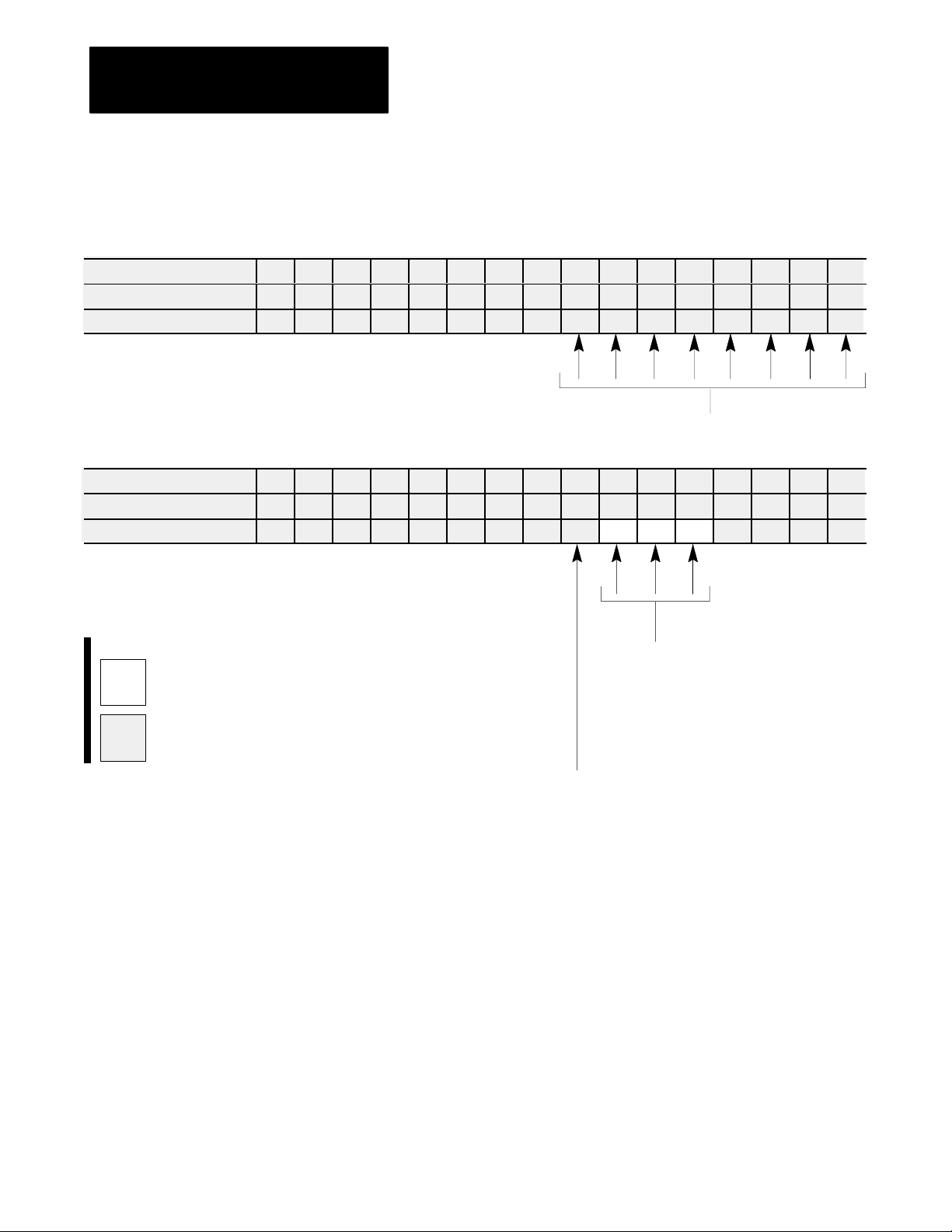
Chapter 7
Load Initial Configuration Values
Worksheet 7D
Clamp Low Pressure Close Configuration Block (LPC)
Control Word LPC01Bxx
ProSet 600 Addr. B37/bit
15 14 13 12 11 10 09 08 07 06 05 04 03 02 01 00
207 206 205 204 203 202 201 200 199 198 197 196 195 194 193 192
Value 0 0 0 0 0 0 0 0 0 0 0 0 0 1 1 0
LPC
Block Identifier
Control Word LPC02Bxx
ProSet 600 Addr. B37/bit
15 14 13 12 11 10 09 08 07 06 05 04 03 02 01 00
223 222 221 220 219 218 217 216 215 214 213 212 211 210 209 208
Value 0 0 0 0 0 0 0 0 1 0 0 0 0
Code:
0
or 1
Your
value
Required initial value
loaded by ProSet 600
Selected
Pressure Valve
000 = Output 1
001 = Output 2
010 = Output 3
011 = Output 4
7-10
PID Pressure Algorithm
0 = Dependent Gains
1 = Independent Gains
Page 92

Chapter 7
Load Initial Configuration Values
Worksheet 7D
(continued)
Clamp Low Pressure Close Configuration Block (LPC)
Enter Y
our V
alues Here
Control Word ProSet 600 Addr. Value Description Units
LPC06 N43:182 1000 Minimum ERC PercentagePressure Percent
LPC07 N43:183 0 Tonnage Watchdog Timer Preset Time
LPC08 N43:184 0 Profile Watchdog Timer Preset Time
LPC09 N43:185 * Output #1 SetOutput Value during Profile Percent Signal Output
LPC10 N43:186 * Output #2 SetOutput Value during Profile Percent Signal Output
LPC11 N43:187 * Output #3 SetOutput Value during Profile Percent Signal Output
LPC12 N43:188 * Output #4 SetOutput Value during Profile Percent Signal Output
LPC17 N43:193 0 Output #1 Acceleration Ramp Rate during Profile Percent Signal Output per Second
LPC18 N43:194 0 Output #2 Acceleration Ramp Rate during Profile Percent Signal Output per Second
LPC19 N43:195 0 Output #3 Acceleration Ramp Rate during Profile Percent Signal Output per Second
LPC20 N43:196 0 Output #4 Acceleration Ramp Rate during Profile Percent Signal Output per Second
LPC25 N43:201 0 Output #1 Deceleration Ramp Rate during Profile Percent Signal Output per Second
LPC26 N43:202 0 Output #2 Deceleration Ramp Rate during Profile Percent Signal Output per Second
LPC27 N43:203 0 Output #3 Deceleration Ramp Rate during Profile Percent Signal Output per Second
LPC28 N43:204 0 Output #4 Deceleration Ramp Rate during Profile Percent Signal Output per Second
LPC33 N43:209 * Output #1 SetOutput Value at Endof Profile Percent Signal Output
LPC34 N43:210 * Output #2 SetOutput Value at Endof Profile Percent Signal Output
LPC35 N43:211 * Output #3 SetOutput Value at Endof Profile Percent Signal Output
LPC36 N43:212 * Output #4 SetOutput Value at Endof Profile Percent Signal Output
LPC41 N43:217 0 Pressure Minimum Control Limit Pressure
LPC42 N43:218 * Pressure Maximum Control Limit Pressure
LPC43 N43:219 * Selected Pressure Valve, Output for Minimum Percent Signal Output
LPC44 N43:220 * Selected Pressure Valve, Output for Maximum Percent Signal Output
LPC49 N43:225 100 Proportional Gain for Pressure Control None
LPC50 N43:226 400 Integral Gain for Pressure Control Inverse Time (Algorithm)
LPC51 N43:227 0 Derivative Gain for Pressure Control Time (Algorithm)
LPC57 N43:233 0 Profile High Pressure Alarm Setpoint Pressure
1
Time
00.00 to 99.99 Seconds
5
Inverse T
ime (Algorithm)
00.00 to 99.99 Minutes (ISA) 00.00 to 99.99 Minutes (ISA)
00.00 to 99.99 Seconds (AB) 00.00 to 99.99 Seconds (AB)
2
Pressure
0000 to 9999 PSI
000.0 to 999.9 Bar
6
T
ime (Algorithm)
3
Percent
Signal Output
00.00 to 99.99
7
Percent
00.00 to 99.99
7
1
1
3
3
3
3
3
3
3
3
2
2
3
3
5
6
2
4
Percent Signal Output per Second
0000 to 9999
4
4
4
4
4
4
4
4
*
Refer to the appropriate section later in this chapter for information on this parameter
7-11
Page 93

Chapter 7
Load Initial Configuration Values
Worksheet 7E
Injection Configuration Block (INC)
Control W
ProSet 600 Addr. B38/bit
ord INC01Bxx
15 14 13 12 11 10 09 08 07 06 05 04 03 02 01 00
15 14 13 12 11 10 09 08 07 06 05 04 03 02 01 00
Value 0 0 0 0 0 0 0 0 0 0 0 0 1 0 0 0
INC
Block Identifier
Control W
ProSet 600 Addr. B38/bit
ord INC02Bxx
15 14 13 12 11 10 09 08 07 06 05 04 03 02 01 00
31 30 29 28 27 26 25 24 23 22 21 20 19 18 17 16
Value 0 0 0 0 0 0 0 0 1 0
Code:
0
or 1
Your
value
Required initial value
loaded by ProSet 600
Selected
Pressure Valve
000 = Output 1
001 = Output 2
010 = Output 3
011 = Output 4
Selected
Velocity Valve
000 = Output 1
001 = Output 2
010 = Output 3
011 = Output 4
7-12
PID Pressure Algorithm
0 = Dependent Gains
1 = Independent Gains
Page 94

Chapter 7
Load Initial Configuration Values
Worksheet 7E(continued)
Enter Y
our V
alues Here
Control Word ProSet 600 Addr. Value Description Units
INC05 N44:1 1000 Minimum ERC PercentageVelocity Percent
INC06 N44:2 1000 Minimum ERC PercentagePressure Percent
INC09 N44:5 * Output #1 Setoutput Value During Profile Percent Signal Output
INC10 N44:6 * Output #2 Setoutput Value During Profile Percent Signal Output
INC11 N44:7 * Output #3 Setoutput Value During Profile Percent Signal Output
INC12 N44:8 * Output #4 Setoutput Value During Profile Percent Signal Output
INC17 N44:13 0 Output #1 Acceleration Ramp Rate During Profile Percent Signal Output per Second
INC18 N44:14 0 Output #2 Acceleration Ramp Rate During Profile Percent Signal Output per Second
INC19 N44:15 0 Output #3 Acceleration Ramp Rate During Profile Percent Signal Output per Second
INC20 N44:16 0 Output #4 Acceleration Ramp Rate During Profile Percent Signal Output per Second
INC25 N44:21 0 Output #1 Deceleration Ramp Rate During Profile Percent Signal Output per Second
INC26 N44:22 0 Output #2 Deceleration Ramp Rate During Profile Percent Signal Output per Second
INC27 N44:23 0 Output #3 Deceleration Ramp Rate During Profile Percent Signal Output per Second
INC28 N44:24 0 Output #4 Deceleration Ramp Rate During Profile Percent Signal Output per Second
INC41 N44:37 0 Pressure Minimum Control Limit Pressure
INC42 N44:38 * Pressure Maximum Control Limit Pressure
INC43 N44:39 * Selected Pressure Valve, Output for Minimum Percent Signal Output
INC44 N44:40 * Selected Pressure Valve, Output for Maximum Percent Signal Output
INC45 N44:41 0 Velocity Minimum Control Limit Velocity along Axis
INC46 N44:42 * Velocity Maximum Control Limit Velocity along Axis
INC47 N44:43 * Selected Velocity Valve, Output for Minimum Percent Signal Output
INC48 N44:44 * Selected Velocity Valve, Output for Maximum Percent Signal Output
INC49 N44:45 100 Proportional Gain for Pressure Control None
INC50 N44:46 400 Integral Gain for Pressure Control Inverse Time (Algorithm)
INC51 N44:47 0 Derivative Gain for Pressure Control Time (Algorithm)
INC52 N44:48 200 Proportional Gain for Velocity Control Inverse Time (Algorithm)
INC53 N44:49 0 Feed Forward Gain for Velocity Control None
INC57 N44:53 0 Profile High Pressure Alarm Setpoint Pressure
2
Velocity along Axis
00.00 to 99.99 inches per second
000.0 to 999.9 millimeters per second
5
Percent Signal Output per Second
0000 to 9999
Injection Configuration Block (INC)
3
Pressure
0000 to 9999 PSI
000.0 to 999.9 Bar
6
Inverse T
ime (Algorithm)
00.00 to 99.99 Minutes (ISA) 00.00 to 99.99 Minutes (ISA)
00.00 to 99.99 Seconds (AB) 00.00 to 99.99 Seconds (AB)
4
Percent Signal Output
00.00 to 99.99
7
T
ime (Algorithm)
8
8
3
3
3
8
4
4
4
4
4
4
2
2
4
4
6
7
6
Percent
00.00 to 99.99
5
5
5
5
5
5
5
5
*
Refer to the appropriate section later in this chapter for information on this parameter
7-13
Page 95

Chapter 7
Load Initial Configuration Values
Worksheet 7F
Pack Configuration Block (PKC)
Control W
ProSet 600 Addr. B38/bit
ord PKC01Bxx
15 14 13 12 11 10 09 08 07 06 05 04 03 02 01 00
143 142 141 140 139 138 137 136 135 134 133 132 131 130 129 128
Value 0 0 0 0 0 0 0 0 0 0 0 0 1 0 1 0
PKC
Block Identifier
Control Word PKC02Bxx
ProSet 600 Addr. B38/bit
15 14 13 12 11 10 09 08 07 06 05 04 03 02 01 00
159 158 157 156 155 154 153 152 151 150 149 148 147 146 145 144
Value 0 0 0 0 0 0 0 0 1 0 0 0 0
Code:
0
or 1
Your
value
Required initial value
loaded by ProSet 600
PID Pressure Algorithm
0 = Dependent Gains
1 = Independent Gains
Selected
Pressure Valve
000 = Output 1
001 = Output 2
010 = Output 3
011 = Output 4
7-14
Page 96

Chapter 7
Load Initial Configuration Values
Worksheet 7F
(continued)
Pack Configuration Block (PKC)
Enter Y
our V
alues Here
Control Word ProSet 600 Addr. Value Description Units
PKC06 N44:122 1000 Minimum ERC PercentagePressure Percent
PKC09 N44:125 * Output #1 Setoutput Value During Profile Percent Signal Output
PKC10 N44:126 * Output #2 Setoutput Value During Profile Percent Signal Output
PKC11 N44:127 * Output #3 Setoutput Value During Profile Percent Signal Output
PKC12 N44:128 * Output #4 Setoutput Value During Profile Percent Signal Output
PKC17 N44:133 0 Output #1 Acceleration Ramp Rate During Profile Percent Signal Output per Second
PKC18 N44:134 0 Output #2 Acceleration Ramp Rate During Profile Percent Signal Output per Second
PKC19 N44:135 0 Output #3 Acceleration Ramp Rate During Profile Percent Signal Output per Second
PKC20 N44:136 0 Output #4 Acceleration Ramp Rate During Profile Percent Signal Output per Second
PKC25 N44:141 0 Output #1 Deceleration Ramp Rate During Profile Percent Signal Output per Second
PKC26 N44:142 0 Output #2 Deceleration Ramp Rate During Profile Percent Signal Output per Second
8
4
4
4
4
5
5
5
5
5
5
PKC27 N44:143 0 Output #3 Deceleration Ramp Rate During Profile Percent Signal Output per Second
PKC28 N44:144 0 Output #4 Deceleration Ramp Rate During Profile Percent Signal Output per Second
PKC41 N44:157 0 Pressure Minimum Control Limit Pressure
PKC42 N44:158 * Pressure Maximum Control Limit Pressure
PKC43 N44:159 * Selected Pressure Valve, Output for Minimum Percent Signal Output
PKC44 N44:160 * Selected Pressure Valve, Output for Maximum Percent Signal Output
5
5
3
3
4
4
PKC49 N44:165 100 Proportional Gain for Pressure Control None
PKC50 N44:166 400 Integral Gain for Pressure Control Inverse Time (Algorithm)
PKC51 N44:167 0 Derivative Gain for Pressure Control Time (Algorithm)
PKC57 N44:173 0 Profile High Pressure Alarm Setpoint Pressure
3
Pressure
0000 to 9999 PSI
000.0 to 999.9 Bar
5
Percent Signal Output per Second
0000 to 9999
*
Refer to the appropriate section later in this chapter for information on this parameter
4
Percent
Signal Output
00.00 to 99.99
6
Inverse T
ime (Algorithm)
00.00 to 99.99 Minutes (ISA)
00.00 to 99.99 Seconds (AB) 00.00 to 99.99 Seconds (AB)
7
T
ime (Algorithm)
00.00 to 99.99 Minutes (ISA)
3
8
Percent
00.00 to 99.99
6
7
7-15
Page 97

Chapter 7
Load Initial Configuration Values
Worksheet 7G
Hold Configuration Block (HDC)
Control W
ProSet 600 Addr. B38/bit
ord HDC01Bxx
15 14 13 12 11 10 09 08 07 06 05 04 03 02 01 00
207 206 205 204 203 202 201 200 199 198 197 196 195 194 193 192
Value 0 0 0 0 0 0 0 0 0 0 0 0 1 0 1 1
HDC
Block Identifier
Control W
ProSet 600 Addr. B38/bit
ord HDC02Bxx
15 14 13 12 11 10 09 08 07 06 05 04 03 02 01 00
223 222 221 220 219 218 217 216 215 214 213 212 211 210 209 208
Value 0 0 0 0 0 0 0 0 1 0 0 0 0
Code:
0
or 1
Your
value
Required initial value
loaded by ProSet 600
Selected
Pressure Valve
000 = Output 1
001 = Output 2
010 = Output 3
011 = Output 4
PID Pressure Algorithm
0 = Dependent Gains
1 = Independent Gains
7-16
Page 98

Chapter 7
Load Initial Configuration Values
Worksheet 7G
(continued)
Hold Configuration Block (HDC)
Enter Y
our V
alues Here
Control Word ProSet 600 Addr. Value Description Units
HDC06 N44:182 1000 Minimum ERC PercentagePressure Percent
HDC09 N44:185 * Output #1 Setoutput Value During Profile Percent Signal Output
HDC10 N44:186 * Output #2 Setoutput Value During Profile Percent Signal Output
HDC11 N44:187 * Output #3 Setoutput Value During Profile Percent Signal Output
HDC12 N44:188 * Output #4 Setoutput Value During Profile Percent Signal Output
HDC17 N44:193 0 Output #1 Acceleration Ramp Rate During Profile Percent Signal Output per Second
HDC18 N44:194 0 Output #2 Acceleration Ramp Rate During Profile Percent Signal Output per Second
HDC19 N44:195 0 Output #3 Acceleration Ramp Rate During Profile Percent Signal Output per Second
HDC20 N44:196 0 Output #4 Acceleration Ramp Rate During Profile Percent Signal Output per Second
HDC25 N44:201 0 Output #1 Deceleration Ramp Rate During Profile Percent Signal Output per Second
HDC26 N44:202 0 Output #2 Deceleration Ramp Rate During Profile Percent Signal Output per Second
HDC27 N44:203 0 Output #3 Deceleration Ramp Rate During Profile Percent Signal Output per Second
HDC28 N44:204 0 Output #4 Deceleration Ramp Rate During Profile Percent Signal Output per Second
HDC33 N44:209 * Output #1 Setoutput Value at Endof Profile Percent Signal Output
HDC34 N44:210 * Output #2 Setoutput Value at Endof Profile Percent Signal Output
HDC35 N44:211 * Output #3 Setoutput Value at Endof Profile Percent Signal Output
HDC36 N44:212 * Output #4 Setoutput Value at Endof Profile Percent Signal Output
HDC41 N44:217 0 Pressure Minimum Control Limit Pressure
HDC42 N44:218 * Pressure Maximum Control Limit Pressure
HDC43 N44:219 * Selected Pressure Valve, Output for Minimum Percent Signal Output
HDC44 N44:220 * Selected Pressure Valve, Output for Maximum Percent Signal Output
HDC49 N44:225 100 Proportional Gain for Pressure Control None
HDC50 N44:226 400 Integral Gain for Pressure Control Inverse Time (algorithm)
HDC51 N44:227 0 Derivative Gain for Pressure Control Time (algorithm)
HDC57 N44:233 0 Profile High Pressure Alarm Setpoint Pressure
3
Pressure
0000 to 9999 PSI
000.0 to 999.9 Bar
5
Percent Signal Output per Second
0000 to 9999
4
Percent
Signal Output
00.00 to 99.99
6
Inverse T
ime (Algorithm)
00.00 to 99.99 Minutes (ISA) 00.00 to 99.99 Minutes (ISA)
00.00 to 99.99 Seconds (AB) 00.00 to 99.99 Seconds (AB)
7
T
ime (Algorithm)
8
4
4
4
4
5
5
5
5
5
5
5
5
4
4
4
4
3
3
4
4
6
7
3
8
Percent
00.00 to 99.99
*
Refer to the appropriate section later in this chapter for information on this parameter
7-17
Page 99

Chapter 7
Load Initial Configuration Values
Worksheet 7H
Plastication Configuration Block (PLC)
Control Word PLC01Bxx
ProSet 600 Addr. B38/bit
15 14 13 12 11 10 09 08 07 06 05 04 03 02 01 00
399 398 397 396 395 394 393 392 391 390 389 388 387 386 385 384
Value 0 0 0 0 0 0 0 0 0 0 0 0 1 1 1 0
PLC
Block Identifier
Control Word PLC02Bxx
ProSet 600 Addr. B38/bit
15 14 13 12 11 10 09 08 07 06 05 04 03 02 01 00
415 414 413 412 411 410 409 408 407 406 405 404 403 402 401 400
Value 0 0 0 0 0 0 0 0 1 0 0 0 0
Code:
0
or 1
Your
value
Required initial value
loaded by ProSet 600
Selected
Pressure Valve
000 = Output 1
001 = Output 2
010 = Output 3
011 = Output 4
7-18
PID Pressure Algorithm
0 = Dependent Gains
1 = Independent Gains
Page 100

Chapter 7
Load Initial Configuration Values
Worksheet 7H
(continued)
Plastication Configuration Block (PLC)
Enter Y
our V
alues Here
Control Word ProSet 600 Addr. Value Description Units
PLC06 N44:362 1000 Minimum ERC PercentagePressure Percent
PLC08 N44:364 0 Profile Watchdog Timer Preset Time
PLC09 N44:365 * Output #1 Setoutput Value During Profile Percent Signal Output
PLC10 N44:366 * Output #2 Setoutput Value During Profile Percent Signal Output
PLC11 N44:367 * Output #3 Setoutput Value During Profile Percent Signal Output
PLC12 N44:368 * Output #4 Setoutput Value During Profile Percent Signal Output
PLC17 N44:373 0 Output #1 Acceleration Ramp Rate During Profile Percent Signal Output per Second
PLC18 N44:374 0 Output #2 Acceleration Ramp Rate During Profile Percent Signal Output per Second
PLC19 N44:375 0 Output #3 Acceleration Ramp Rate During Profile Percent Signal Output per Second
PLC20 N44:376 0 Output #4 Acceleration Ramp Rate During Profile Percent Signal Output per Second
PLC25 N44:381 0 Output #1 Deceleration Ramp Rate During Profile Percent Signal Output per Second
PLC26 N44:382 0 Output #2 Deceleration Ramp Rate During Profile Percent Signal Output per Second
PLC27 N44:383 0 Output #3 Deceleration Ramp Rate During Profile Percent Signal Output per Second
PLC28 N44:384 0 Output #4 Deceleration Ramp Rate During Profile Percent Signal Output per Second
PLC33 N44:389 * Output #1 Setoutput Value at Endof Profile Percent Signal Output
PLC34 N44:390 * Output #2 Setoutput Value at Endof Profile Percent Signal Output
PLC35 N44:391 * Output #3 Setoutput Value at Endof Profile Percent Signal Output
PLC36 N44:392 * Output #4 Setoutput Value at Endof Profile Percent Signal Output
PLC41 N44:397 0 Pressure Minimum Control Limit Pressure
PLC42 N44:398 * Pressure Maximum Control Limit Pressure
PLC43 N44:399 * Selected Pressure Valve, Output for Minimum Percent Signal Output
PLC44 N44:400 * Selected Pressure Valve, Output for Maximum Percent Signal Output
PLC49 N44:405 100 Proportional Gain for Pressure Control None
PLC50 N44:406 400 Integral Gain for Pressure Control Inverse Time (Algorithm)
PLC51 N44:407 0 Derivative Gain for Pressure Control Time (Algorithm)
PLC57 N44:413 0 Profile High Pressure Alarm Setpoint Pressure
1
Time
00.00 to 99.99 seconds
5
Percent Signal Output per Second
0000 to 9999
3
Pressure
0000 to 9999 PSI
000.0 to 999.9 Bar
6
Inverse T
ime (Algorithm)
00.00 to 99.99 Minutes (ISA) 00.00 to 99.99 Minutes (ISA)
00.00 to 99.99 Seconds (AB) 00.00 to 99.99 Seconds (AB)
4
Percent
00.00 to 99.99
7
T
ime (Algorithm)
Signal Output
8
1
3
3
3
8
Percent
00.00 to 99.99
4
4
4
4
4
4
4
4
4
4
6
7
5
5
5
5
5
5
5
5
*
Refer to the appropriate section later in this chapter for information on this parameter
7-19
 Loading...