

Page 1

AllenBradley
Servo Positioning
Assembly
User
(Cat.
No. 1771-QC Series B)
Manual
Page 2

Table of Contents
Using This Manual 11. . . . . . . . . . . . . . . . . . . . . . . . . . . . . . .
Manual's Purpose 11. . . . . . . . . . . . . . . . . . . . . . . . . . . . . . . . . . .
Audience 11
Vocabulary 11
Manual Organization 12
Introducing the Servo Positioning Assembly 21. . . . . . . . . . .
. . . . . . . . . . . . . . . . . . . . . . . . . . . . . . . . . . . . . . . . . .
. . . . . . . . . . . . . . . . . . . . . . . . . . . . . . . . . . . . . . . .
. . . . . . . . . . . . . . . . . . . . . . . . . . . . . . . . .
Chapter
What is the Servo Positioning Assembly? 21
Its
Its Function 22
Its Features 24
Summary 27
Objectives
Applications
. . . . . . . . . . . . . . . . . . . . . . . . . . . . . . . . . . . . . . . .
. . . . . . . . . . . . . . . . . . . . . . . . . . . . . . . . . . . . . . . .
. . . . . . . . . . . . . . . . . . . . . . . . . . . . . . . . . . . . . . . . .
21. . . . . . . . . . . . . . . . . . . . . . . . . . . . . . . . . . .
. . . . . . . . . . . . . . . . . . .
22. . . . . . . . . . . . . . . . . . . . . . . . . . . . . . . . . . . . .
Positioning Concepts 31. . . . . . . . . . . . . . . . . . . . . . . . . . . .
Chapter
ClosedLoop
Leadscrew
Encoder Feedback 37
Summary 311
Objectives
Positioning
Pitch
. . . . . . . . . . . . . . . . . . . . . . . . . . . . . . . . . . .
. . . . . . . . . . . . . . . . . . . . . . . . . . . . . . . . . . . . . . . . .
31. . . . . . . . . . . . . . . . . . . . . . . . . . . . . . . . . . .
31. . . . . . . . . . . . . . . . . . . . . . . . . . . . . . .
36. . . . . . . . . . . . . . . . . . . . . . . . . . . . . . . . . . . .
Positioning With an AllenBradley Programmable Controller 41
Chapter
Where the Servo Positioning Assembly Fits In 41
Independent
Move/Moveset 42
In
Synchronizing Axes 48
Specifying
Summary 413
Objectives
Position
. . . . . . . . . . . . . . .
of I/O Scan
. . . . . . . . . . . . . . . . . . . . . . . . . . . . . . . . . . . . . .
. . . . . . . . . . . . . . . . . . . . . . . . . . . . . . . . . .
Axis Position
. . . . . . . . . . . . . . . . . . . . . . . . . . . . . . . . . . . . . . . . .
41. . . . . . . . . . . . . . . . . . . . . . . . . . . . . . . . . . .
42. . . . . . . . . . . . . . . . . . . . . . . . . . . . . . .
48. . . . . . . . . . . . . . . . . . . . . . . . . . . . . . . . . . . . . . . . .
410. . . . . . . . . . . . . . . . . . . . . . . . . . . . . . .
Hardware Description 51. . . . . . . . . . . . . . . . . . . . . . . . . . . .
Chapter
Indicators 51
Inputs/Outputs 52
External Power Supplies 57
Compatible Processors 58
Fault Responses 59
Specifications 511
Summary 513
Objectives
. . . . . . . . . . . . . . . . . . . . . . . . . . . . . . . . . . . . . . . . .
. . . . . . . . . . . . . . . . . . . . . . . . . . . . . . . . . . . . . .
. . . . . . . . . . . . . . . . . . . . . . . . . . . . . . .
. . . . . . . . . . . . . . . . . . . . . . . . . . . . . . .
. . . . . . . . . . . . . . . . . . . . . . . . . . . . . . . . . . . .
. . . . . . . . . . . . . . . . . . . . . . . . . . . . . . . . . . . . . .
. . . . . . . . . . . . . . . . . . . . . . . . . . . . . . . . . . . . . . . . .
51. . . . . . . . . . . . . . . . . . . . . . . . . . . . . . . . . . .
Page 3

Table of Contentsii
Installing the Assembly 61. . . . . . . . . . . . . . . . . . . . . . . . . . .
Chapter
Configuring the Modules 61
Setting Switches and Jumpers 63
Keying 67
Inserting the Module 69
Connecting
Connecting AB Encoder and Drive 627
Startup Sequence 631
Summary 632
Objectives
. . . . . . . . . . . . . . . . . . . . . . . . . . . . . . .
. . . . . . . . . . . . . . . . . . . . . . . . . .
. . . . . . . . . . . . . . . . . . . . . . . . . . . . . . . . . . . . . . . . . . .
. . . . . . . . . . . . . . . . . . . . . . . . . . . . . . . . . .
to T
erminals 610. . . . . . . . . . . . . . . . . . . . . . . . . . . . . . .
. . . . . . . . . . . . . . . . . . . . . . .
. . . . . . . . . . . . . . . . . . . . . . . . . . . . . . . . . . .
. . . . . . . . . . . . . . . . . . . . . . . . . . . . . . . . . . . . . . . . .
61. . . . . . . . . . . . . . . . . . . . . . . . . . . . . . . . . . .
Formatting and Interpreting Data Blocks 71. . . . . . . . . . . . . .
Chapter
Relationship of Data Blocks 71
Status Block 74
Parameter Block 717
Moveset Block 740
Command Block 760
Summary 779
Objectives
. . . . . . . . . . . . . . . . . . . . . . . . . . . . .
. . . . . . . . . . . . . . . . . . . . . . . . . . . . . . . . . . . . . . .
. . . . . . . . . . . . . . . . . . . . . . . . . . . . . . . . . . . .
. . . . . . . . . . . . . . . . . . . . . . . . . . . . . . . . . . . . . .
. . . . . . . . . . . . . . . . . . . . . . . . . . . . . . . . . . . .
. . . . . . . . . . . . . . . . . . . . . . . . . . . . . . . . . . . . . . . . .
71. . . . . . . . . . . . . . . . . . . . . . . . . . . . . . . . . . .
Programming 81. . . . . . . . . . . . . . . . . . . . . . . . . . . . . . . . . . .
Chapter
Programming
PLC2 Family Block Transfer Instructions 83
PLC2Family Block Transfer Timing 86
PLC3 Block Transfer Instructions 813
PLC3 Block Transfer Timing 814
Programming Example 821
Summary 840
Objectives
Objectives
. . . . . . . . . . . . . . . . . . .
. . . . . . . . . . . . . . . . . . . . . .
. . . . . . . . . . . . . . . . . . . . . . . .
. . . . . . . . . . . . . . . . . . . . . . . . . . . .
. . . . . . . . . . . . . . . . . . . . . . . . . . . . . . . .
. . . . . . . . . . . . . . . . . . . . . . . . . . . . . . . . . . . . . . . . .
81. . . . . . . . . . . . . . . . . . . . . . . . . . . . . . . . . . .
81. . . . . . . . . . . . . . . . . . . . . . . . . . . . . . .
Integrating Axes 91. . . . . . . . . . . . . . . . . . . . . . . . . . . . . . . .
Chapter
OpenLoop Procedure 91
ClosedLoop Procedure 96
Tachometer
Summary 911
Objectives
. . . . . . . . . . . . . . . . . . . . . . . . . . . . . . . .
. . . . . . . . . . . . . . . . . . . . . . . . . . . . . . .
Calibration
. . . . . . . . . . . . . . . . . . . . . . . . . . . . . . . . . . . . . . . . .
91. . . . . . . . . . . . . . . . . . . . . . . . . . . . . . . . . . .
98. . . . . . . . . . . . . . . . . . . . . . . . . . . . . . . .
Troubleshooting 101. . . . . . . . . . . . . . . . . . . . . . . . . . . . . . . .
Chapter
Monitoring 1771M3 Controller Indicators 101
Monitoring 1771ES Expander Indicators 103
Monitoring the Status Block 104
Troubleshooting Flowchart 107
Summary 1012
Objectives
. . . . . . . . . . . . . . . . . . .
. . . . . . . . . . . . . . . . . . .
. . . . . . . . . . . . . . . . . . . . . . . . . . . . .
. . . . . . . . . . . . . . . . . . . . . . . . . . . . .
. . . . . . . . . . . . . . . . . . . . . . . . . . . . . . . . . . . . . . . . .
101. . . . . . . . . . . . . . . . . . . . . . . . . . . . . . . . . . .
Page 4

Table of Contents iii
Glossary A1. . . . . . . . . . . . . . . . . . . . . . . . . . . . . . . . . . . . . .
Status Block B1. . . . . . . . . . . . . . . . . . . . . . . . . . . . . . . . . . .
Parameter Block C1. . . . . . . . . . . . . . . . . . . . . . . . . . . . . . . .
Moveset Block 61. . . . . . . . . . . . . . . . . . . . . . . . . . . . . . . . . .
Command Block E1. . . . . . . . . . . . . . . . . . . . . . . . . . . . . . . .
Page 5

Using This Manual
Chapter
1
Manual's Purpose
Audience
Vocabulary
This manual shows you how to use the series B Servo Positioning
Assembly (cat. no. 1771-QC). If you have a series A Servo Positioning
Assembly, refer to publication 1771-817.
To use the servo positioning assembly, you must be able to program and
operate an Allen-Bradley PC processor. In particular, you must be able to
program block transfer instructions.
In this manual, we assume that you know how to do this. If you don’t,
refer to the appropriate manual for the PC processor you will be using.
Consult our Publication Index (publication SD499) for a list of our
publications.
Some inconsistency exists throughout industry in the nomenclature used
for components of closed-loop servo positioning systems. Therefore, as
you read this manual, you should be aware of the names we use for these
components.
We refer to the Servo Controller Module (cat. no. 1771-M3) as the
1771-M3 controller.
We refer to the Servo Expander Module (cat. no. 1771-ES) as the
1771-ES expander.
We refer to the device that receives the velocity command signal from
the 1771-ES expander as the servo drive. The servo drive converts ac
power to dc power for the servo motor in proportion to the velocity
command signal. What we refer to here as the servo drive, others may
refer to as a servo controller. So, if you refer to this device as a servo
controller, be aware of our nomenclature as you read this manual.
PC refers to programmable controller.
For an extensive list of terms we use this publication, refer to the glossary
in appendix A.
11
Page 6

Chapter 1
Troubleshooting
Manual Organization
This manual is organized into the following chapters:
Chapter Title What's
2
3
4
5
6
7
Introducing the Servo
Positioning Assembly
Positioning Concepts concepts of closedloop positioning,
Positioning with
AllenBradley PC'
Describing Hardware
Installing the Assembly installing the servo positioning assembly
Formatting and
Interpreting Data Blocks
s
an overview of the servo positioning
assembly
features
including velocity loop, positioning loop, and
feed forward
the servo positioning assembly'
a servo system, and the servo positioning
assembly'
processor
describing the servo positioning assembly
its specifications, and its compatibility with
other hardware components you will need
for a closedloop positioning system
and interconnecting hardware
formatting parameter
and control data for block transfer to the
servo positioning assemblyinterpreting
status and diagnostic data received in block
transfer from the servo positioning
assembly
, its applications, functions, and
s communication with the PC
Covered
, move description,
s position in
,
12
8 Programming
9
10 Troubleshooting
Integrating Axes
generating a ladderdiagram program to
transfer data blocks between the PC data
table and the servo positioning assembly
adjusting the servo positioning assembly for
optimum operation with the machine axis it
is to control
using indicator status and statusblock
information to diagnose and correct
problems
Page 7

Chapter
2
Introducing the Servo Positioning Assembly
Chapter Objectives
What is the Servo Positioning
Assembly?
This chapter gives you an overview of the servo positioning assembly, its
applications, functions and features.
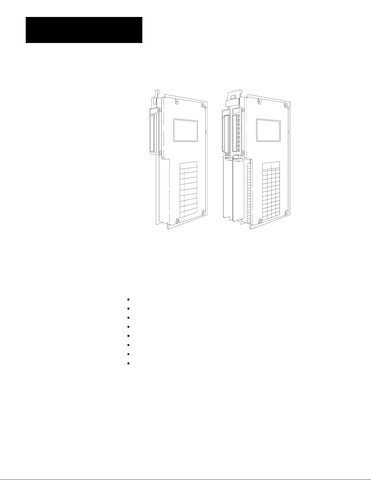
A servo positioning assembly controls the motion of one of your axes. It
consists of:
one Servo Controller Module (cat. no.1771-M3)
one Servo Expander Module (cat. no. 1771-ES) that includes two Field
Wiring Arms (cat. no. 1771-WB)
With a basic servo positioning assembly (plus a servo drive, motor,
tachometer, and encoder) you can control the motion of one user-supplied
machine axis. You can add a second 1771-ES expander to control a
second axis and a third 1771-ES expander to control a third axis. A 1771
I/O chassis can accommodate one 1771-M3 controller and a maximum of
three 1771-ES expanders.
The 1771-M3 controller requires one I/O chassis slot; it requires no
wiring (figure 2.1a). You can install it at any I/O slot in the I/O chassis.
The 1771-ES expander requires a pair of slots that make up an I/O module
group (Figure 2.1b). You make all wiring connections to the 1771-ES
expander.
21
Page 8
Chapter 2
Introducing the Servo Positioning Assembly
Figure 2.1
Servo
Positioning Assembly
Its Applications
Its Function
(a)Servo
Controller Module
(cat.no.1771-M3)
(b)ServoexpanderModule
(cat.no.1771-ES)
17954
Typical applications for a servo positioning assembly include positioning
for:
grinding
transfer lines
material handling
drilling
riveting
rotary indexing
v-belt cutting
glass cutting
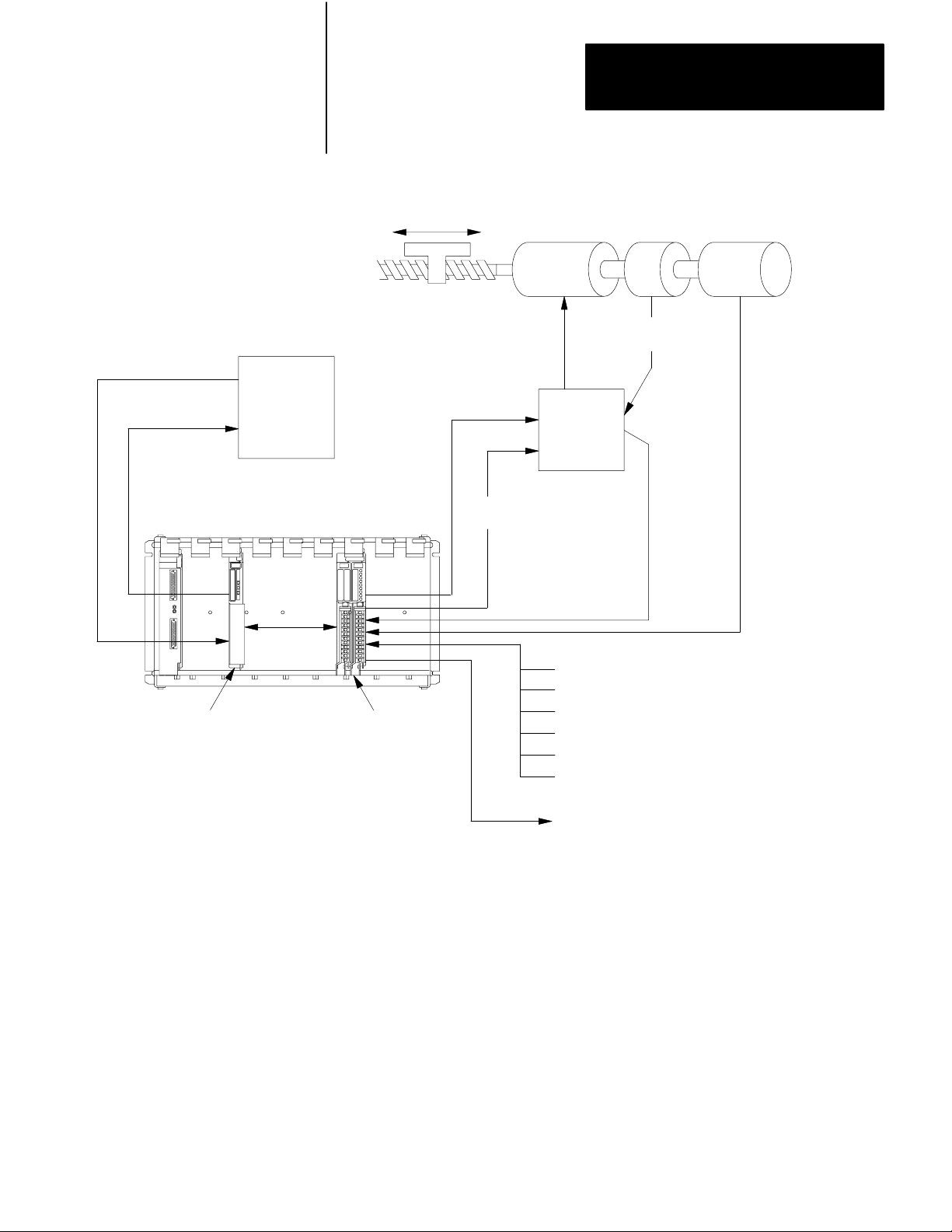
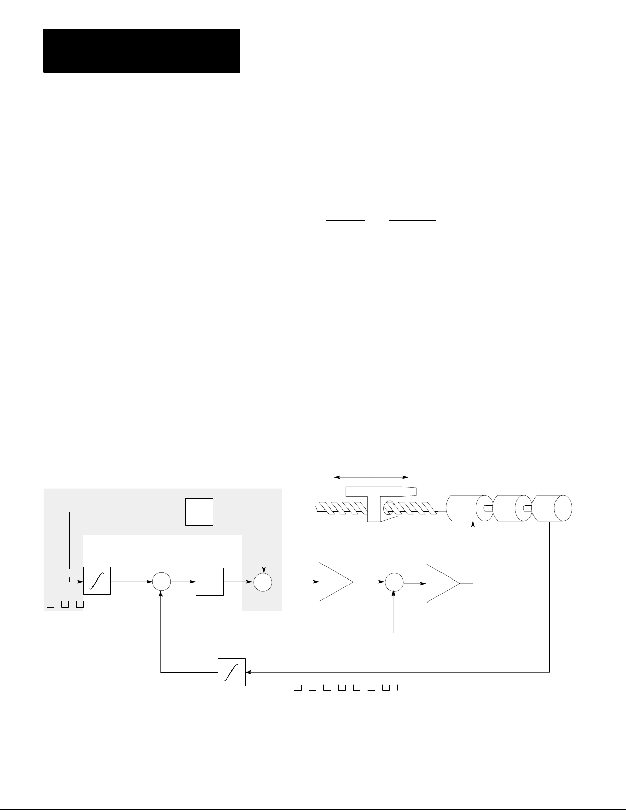
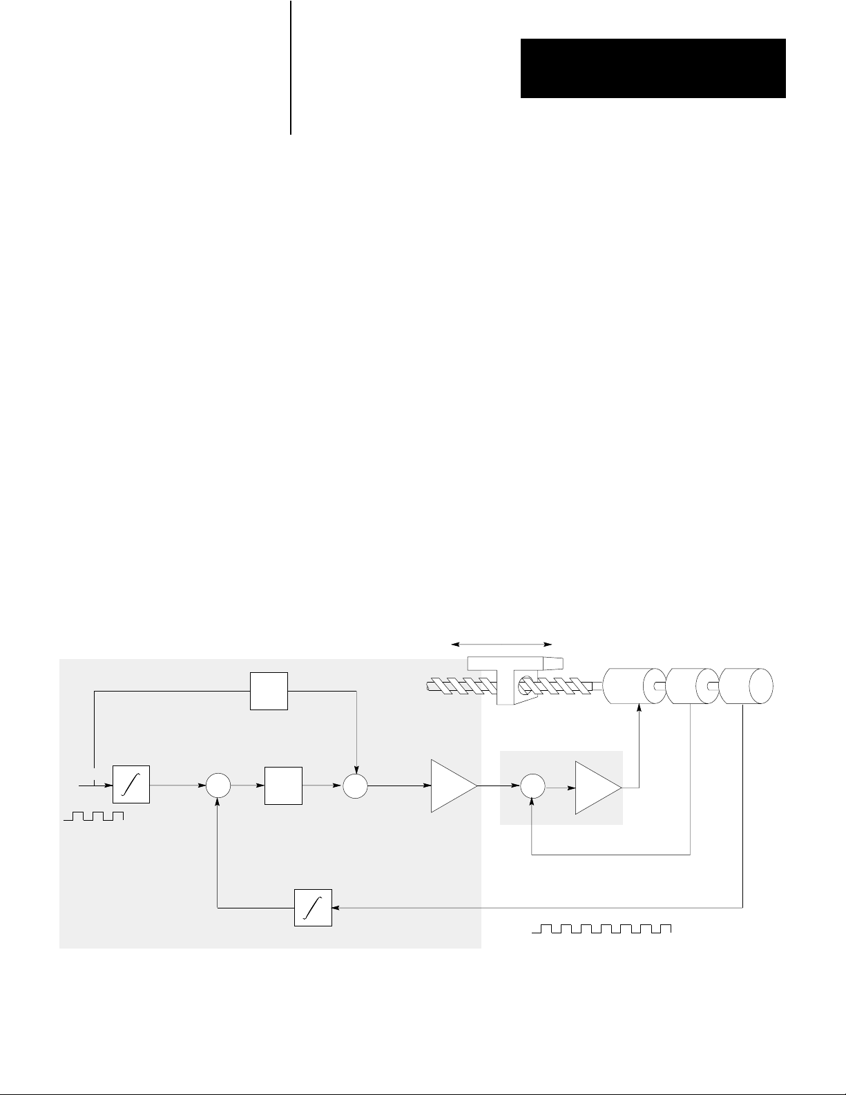
Figure 2.2 shows a servo system for closed-loop axis control. The
1771-M3 controller communicates with the 1771-ES expander through
I/O chassis backplane connections.
22
Page 9
Chapter 2
Introducing the Servo Positioning Assembly
Command
Position Data
Status
Block
PC
Processor
Figure 2.2
Closedloop
Axis Servo System
Axis Motion
Velocity
Command
Drive
Disable
Motor Tach Encoder
Velocity
Feedback
Servo
Drive
Tach Input for
Loss-of-Feedback
Detection
Position
Feedback
Servo Controller
(cat. no. 1771 -M3)
NOTE:
A second and third Servo Expander Module
could be installed in this I/O chassis for control
of a second and third axis.
Servo Expander
(cat. no. 1771 -ES)
The PC processor sends commands and user-programmed data from the
data table to the 1771-M3 controller as directed by a block-transfer write
instruction. The 1771-M3 controller coordinates the block transfer
automatically, keeping ladder diagram programming to a minimum.
Based on information it receives from the processor, the 1771-M3
controller sends axis motion commands to the 1771-ES expander.
The 1771-ES expander closes the servo positioning loop. It commands
axis motion by generating an analog voltage for your servo drive. Every
2.4 milliseconds (ms) it updates this analog output voltage according to
motion commands from the 1771-M3 controller, discrete inputs, and
Discrete Inputs:
Jog Forward
Jog Reverse
Home Limit Switch
Hardware Stop
Hardware Start
Feedrate Enable
Discrete Output:
Hardware Done
10998
23
Page 10

Chapter 2
Introducing the Servo Positioning Assembly
feedback from your encoder. The 1771-ES expander is able to provide
this fast servo sample rate because the update is independent of the I/O
scan.
A drive-disable output provides a signal to disable the servo drive in
conditions such as loss-of-feedback or a hardware-stop signal. A
hardware-done output signals the completion of each single-step move.
Discrete hardware inputs include:
hardware stop
jog forward
jog reverse
home limit
feedrate enable
hardware start
Its Features
The 1771-M3 controller sends axis status and diagnostic data to the data
table as directed by a block-transfer read instruction. Because
axis-command and status data is stored in the data table, axis motion
control can interact with other axes, discrete I/O, and report generation.
See the following table for a list of the many useful benefits you’ss derive
from an A-B servo positioning assembly.
24
Page 11

Chapter 2
Introducing the Servo Positioning Assembly
Feature Benefit
incremental
encoder feedbac
absolute or incremental
positioning commands
programmable gain break
programmable
acceleration/deceleration
programmable inposition
band
programmable jog rates
programmable dwell precise dwell times
digital
k
precise closedloop positioning
programming flexibility
precise positioning at low speed with
stability at high speed
optimize the machine cycle time over
varying loads
flexible positioning accuracy
flexible manual positioning
excessfollowingdetection
lossoffeedback detection
software travel limits guards against axis overtravel
backlash takeup
offset
preset
automatic drive shutdown if the axis
following error becomes too large
allow automatic drive shutdown during
a move if tachometer or encoder
feedback is lost
compensates for mechanical backlash
compensates for a variation in tool
length or fixture dimension
easy redefinition of axis coordinates
25
Page 12

Chapter 2
Introducing the Servo Positioning Assembly
Feature Benefit
optically isolated guards against noise entering the
analog output
[1]
backplane circuits and limits the
potential for damage due to improper
connection
external hardware start
encoder input selectable
for hightrue or lowtrue
synchronized start of
feedrate override
[1]
sensing of customer
power supply loss
feed forwarding
[1]
[1]
[1]
[1]
synchronizes moves with other axes
compatibility with a wider range of
encoders
activates a preloaded feedrate
override value to change speed on
several axes simultaneously
an orderly shutdown of the servo
system and to provide you with this
diagnostic information
to allow you to reduce following error
by up to 99.9% without increasing
instability
26
constantvelocity
command
moveset override
[1]
[1]
diagnostic words in the
status block
[1]
for
runs an axis continuously at a selected
velocity (could apply to controlling a
conveyor with no programmed end
point)
Modifies a moveset while it is being
executed
provide your ladderdiagram program
with access to diagnostic information
hardware and program
troubleshooting
Page 13

Chapter 2
Introducing the Servo Positioning Assembly
[1]
These features are only available on the series B servo positioning
assembly.
Summary
This chapter was intended to be very general. Upcoming chapters cover
these topics in greater detail. To prepare for those details, read about
positioning concepts in chapter 3.
27
Page 14

Positioning Concepts
Chapter
3
Chapter Objectives
ClosedLoop Positioning
This chapter presents positioning concepts and terminology. If you are
thoroughly familiar with the concepts of closed-loop servo positioning,
you can skip ahead to chapter 4.
Closed-loop positioning is a precise means of moving an object from one
position to another. Typically, an electric motor supplies the mechanical
power, and the needed motion is linear. Therefore, we must convert the
rotary motion of the motor’s shaft to linear motion.
Axis Motion
One common method of converting rotary motion to linear motion is with
a leadscrew (Figure 3.1)
Figure 3.1
Leadscrew
Converting Rotory Motor Motion Into Linear Axis Motion
Axis Motion
Slide
Motor
The leadscrew assembly is referred to as the axis. A leadscrew assembly
consists of a long threaded shaft (the leadscrew) and slide having an
internal thread that matches the leadscrew. When the motor rotates the
leadscrew clockwise, the slide moves forward. When the motor rotates
the leadscrew counterclockwise, the slide moves backward.
Shaft
Rotation
11999
31
Page 15
Chapter 3
Positioning Concepts
Velocity Loop
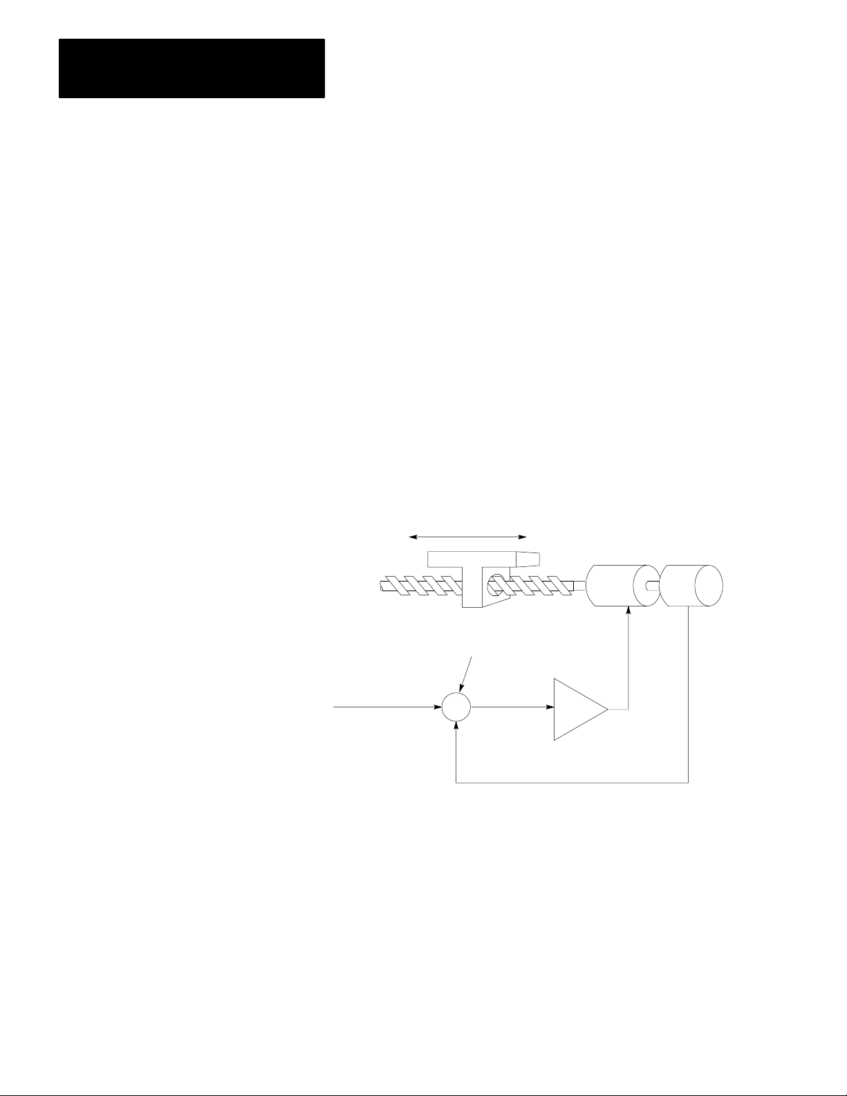
Most closed-loop servo positioning installations use a dc motor to power
the leadscrew. To accurately control the velocity of the dc motor, we need
a velocity loop (Figure 3.2).
The velocity loop contains a summing point, an amplifier, and a
tachometer. A tachometer is a precision generator that produces a voltage
signal directly proportional to the angular velocity of the motor shaft. The
output of the tachometer is the velocity feedback signal which is
subtracted from the velocity command signal. The difference is the
velocity error signal that is amplified to provide power for the motor to
run at the commanded velocity.
Figure 3.2
Velocity
Loop
Velocity
Command
Axis Motion
Motor
Summing Point
Amplifier
+
Velocity
Error
-
Velocity Feedback
Velocity Error = (Velocity Command Velocity Feedback)
Tach
12000
32
Whenever the velocity deviates from the commanded velocity, the
velocity feedback signal adjusts the velocity error signal until the velocity
matches the velocity command signal.
Page 16
Chapter 3
Positioning Concepts
Positioning Loop
When we want to move the slide a specific distance, we can turn the
motor on at a specific velocity for a specific length of time. However, this
could produce imprecise positioning. To accurately control the position
of the slide, we need a positioning loop (Figure 3.3).
Axis
Feedrate
Figure 3.3
Velocity
Following Error = (Position Command) - Position
Position
Command
Following
Error
+
-
Position
K
1
Loop and Positioning Loop
D/A
Velocity
Command
Axis Motion
+
-
Velocity Feedback
Incremental Position Feedback
Motor
Amplifier
Encoder
Tach
12001
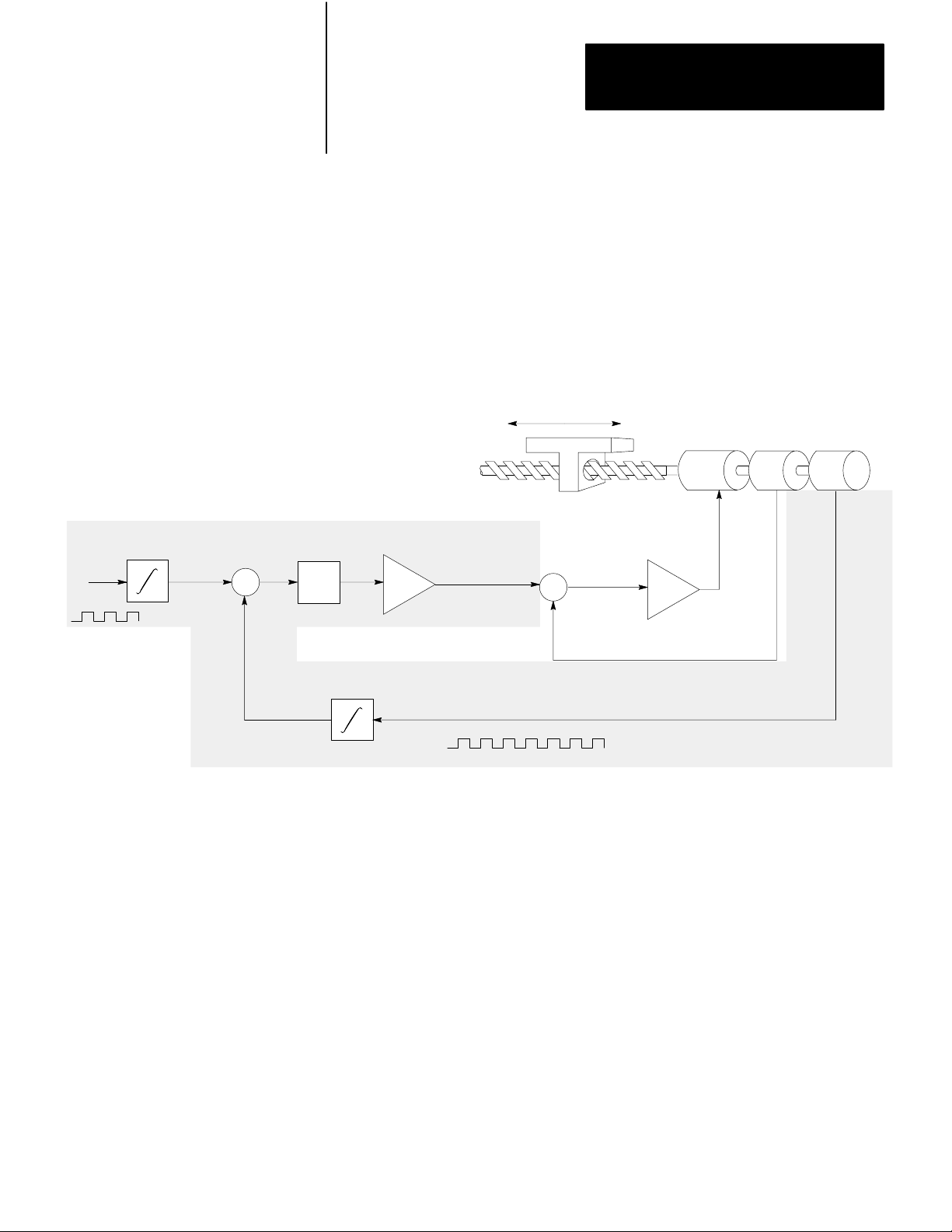
The positioning loop includes a summing point, an amplifier, a D/A
converter, and an incremental digital encoder to produce a position
feedback signal. The axis feedrate is integrated in a register to produce
the position command value. Incremental position feedback is integrated
in a register to produce the actual position value. The position value is
subtracted from the position command value. The difference is the
following error, which is amplified and converted to an analog velocity
command signal. This signal directs the axis to move in the right
direction; the position value moves closer to the position command value.
The following error is a function of the axis velocity divided by the
positioning-loop gain (K1). The following error is multiplied by the gain
33
Page 17
Chapter 3
Positioning Concepts
to generate the velocity command. Gain is expressed in ipm/mil (where 1
mil - 0.001 in) or mmpm/mil (where 1 mil = 0.001 mm).
For example, with a velocity of 100 ipm and a gain of 1 ipm/mil, the
following error is:
velocity
2following error =gain = 1 ipm/mil = 100 mil
When you increase the gain, you decrease the following error and
decrease the cycle time of the system. However, the gain that you can use
is limited by the drive, the motor, and the machine; a gain that is too large
causes instability.
Feed Forward
To decrease the following error without increasing the gain, we can add a
feed forward component (Figure 3.4).
Figure 3.4
Velocity
Velocity Command = K (following Error) - K (Axis Feedrate)
1
2
K
2
Loop, Positioning Loop, and Feed Forwarding
Feed
Forward
100 ipm
Axis Motion
Motor
Encoder
Tach
Axis
Feedrate
34
Position
Command
+
-
Following
Error
Position
Velocity
+
K
1
+
Command
D/A
Incremental Position Feedback
+
-
Velocity Feedback
12002
Page 18

Chapter 3
Positioning Concepts
Feed forwarding requires an additional summing point and an amplifier.
The axis feedrate is multiplied by the feed-forward gain (K2) to produce
the feed-forward value. The feed-forward value is added to the following
error multiplied by the gain to generate the velocity command.
Without feed forward, the axis will not begin to move until the axis
feedrate builds up enough following error to generate a sufficiently large
velocity command to overcome friction and inertia to move the axis.
However, the feed-forward value could generate a velocity command to
move the axis almost immediately. This immediate response keeps the
actual position closer to the position command, thereby reducing the
following error.
35
Page 19
Chapter 3
Positioning Concepts
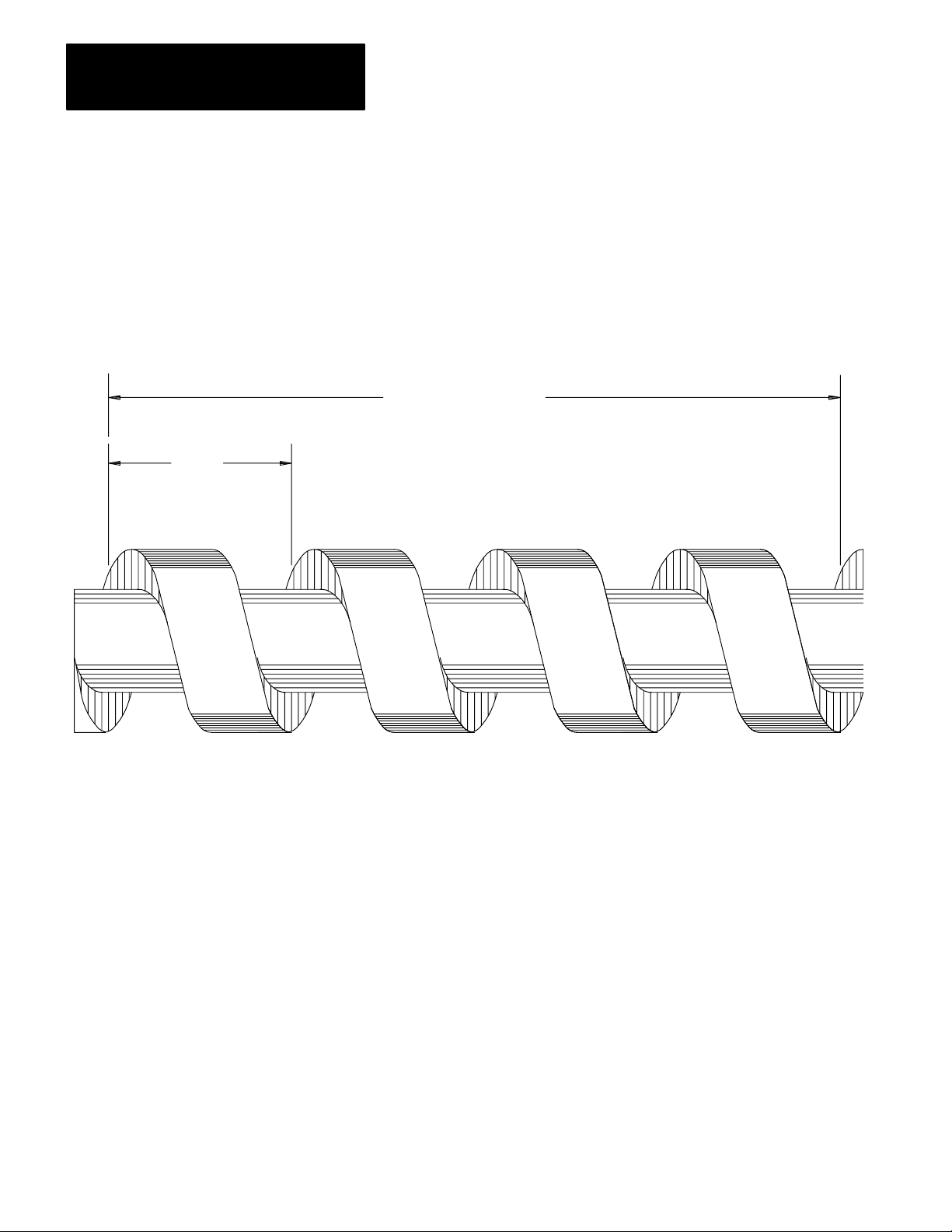
Leadscrew Pitch
Pitch is
1/4 inch
in this
example
Leadscrew pitch is the linear distance from one peak of the screw thread
to the next. A leadscrew with a pitch of 1/4 inch is shown in Figure 3.5.
Figure 3.5
Leadscrew
Example Showing Pitch
4 threads per inch
(4 pitch) in this example
36
12003
If the leadscrew has only one thread, the pitch is also equal to the lead,
which is the distance the axis travels each revolution of the leadscrew.
You can see from Figure 3.5 that the axis will travel 1/4 inch per
revolution if the pitch is 1/4 inch. Since leadscrews normally have only
one thread, and pitch is a more common term than lead, in this publication
we use the term pitch to refer to the distance the axis travels for each
revolution of the leadscrew.
Do not confuse leadscrew pitch with its inverse, which is the number of
pitch (threads) per inch. In the example of Figure 3.5, the leadscrew has 4
pitch (threads) per inch. A leadscrew with a pitch of 1/4 inch is often
described as being a 4-pitch (per inch) leadscrew.
Page 20
Chapter 3
Positioning Concepts
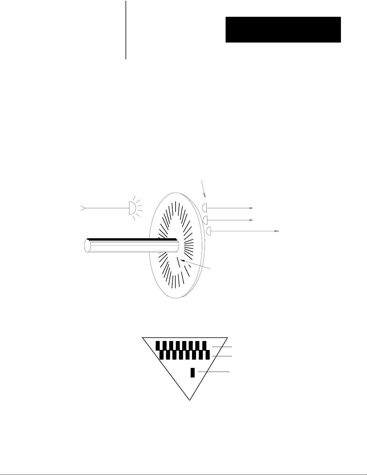
Encoder Feedback
Light
Source
An incremental digital encoder provides feedback that indicates the
magnitude and direction of any change of axis position. As shown in
Figure 3.6, the encoder shaft is attached to a transparent disc marked with
uniformly spaced lines. Strategically located photodiodes detect light. As
the disc rotates, the lines break up the light reaching the photodiodes. As
a result, the output (channel A, channel B, and marker) from each
photodiode is a series of electrical pulses.
Figure 3.6
Incremental
Encoder Showing How Signals Are Generated
Photodetectors
Channel A
Channel B
Marker
Disc
Marker
A
B
Marker
11000
37
Page 21
Chapter 3
Positioning Concepts
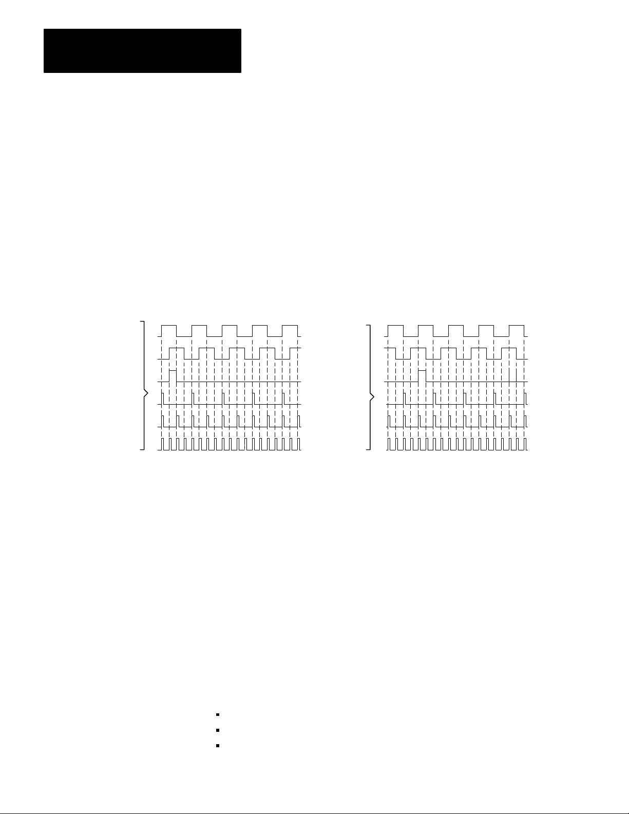
Channel Phase Relationship
The photodetectors are placed so that the channel A and channel B output
signals are out of phase by 90
o
(Figure 3.7). The lead/lag relationship of
these signals indicates the direction of axis motion. Also, the phase
relationship of these signals allow the decoding circuit to count either 1, 2,
or 4 feedback pulses for each line of the encoder (Figure 3.7). This
provides flexibility in establishing feedback resolution.
Channel A
Channel B
Marker
Figure 3.7
Encoder
Forward
x1
x2
x4
Signals Showing Phase Relationship
Channel A
Channel B
Marker
x1
x2
x4
Note: For the servo positioning assembly, the encoder
marker must be high when both channel A and channel
B are high, or the marker is not recognized unless you
set the marker logic jumper to the notgated position.
Reverse
11001
38
Feedback Resolution
The following discussion of feedback resolution assumes that you are
using a leadscrew, and that the encoder is coupled directly to the
leadscrew with no intermediate gearing. These assumptions apply to
many applications. If your application differs, be sure to account for the
differences.
Feedback resolution is the smallest axis movement the servo positioning
system can detect. It is determined by:
leadscrew pitch - axis displacement per revolution
encoder lines - number of lines per revolution
feedback multiplier - selected as x 1, x2, or x4
Page 22

Chapter 3
Positioning Concepts
The following equation shows how these factors determine feedback
resolution:
leadscrew pitch
feedback resolution = (encoder lines) (feedback multiplier)
You must select the leadscrew pitch, encoder lines, and feedback
multiplier to provide desired feedback resolution and meet other
requirements of your application.
The programming resolution of the servo positioning system is 0.0001
inch or 0.001 millimeter. If you select a feedback resolution coarser than
that, round off your position commands so that the effective programming
resolution is no finer than the feedback resolution you chose.
If you select a feedback resolution finer than the programming resolution,
positioning can be smoother. However, the maximum axis speed is
directly proportional to the feedback resolution. There is always a
trade-off between feedback resolution and maximum axis speed. The
maximum encoder input frequency for the servo positioning assembly is
250kHz. Therefore, to avoid a programming error, you must limit the axis
speed to conform to this formula:
programmed 1.5 x 10
7
axis speed < 1.28 x feedback res x feedback mult
The 1.28 factor allows for a 127% feedrate override value.
Each encoder line represents a fraction of a revolution of the leadscrew.
For example, consider a 250 line encoder. Each line represents 1/250 of a
revolution of the leadscrew.
Also, consider a 4-pitch (per inch) leadscrew for this example. The slide
moves 1/4 inch for each revolution. With an x1 multiplier, each feedback
increment represents 1/250 of 1/4 inch or 0.001 inch slide movement.
This is the feedback resolution.
0.25 in/rev
feedback resolution = 250 lines/rev x 1 increment/line
= 0.001 in/increment
39
Page 23

Chapter 3
Positioning Concepts
Therefore, if we cause the leadscrew to move the slide 2 inches, we will
get 2,000 feedback pulses.
Now, consider replacing the 250-line encoder with a 500-line encoder. By
doubling the number of feedback pulses per revolution of the leadscrew,
we improve the feedback resolution from 0.001 inch to 0.0005 inch.
Another way to improve feedback resolution is to use a higher feedback
multiplier. You can select a multiplier of x1, x2, or x4. For example, with
the 4-pitch (per inch) leadscrew and the 250-line encoder, if you select an
x2 multiplier you get the same feedback resolution improvement of from
0.001 inch to 0.0005 inch. With an x4 multiplier, you improve the
feedback resolution to 0.00025 inch.
Marker
Besides the channel A and B output, an incremental encoder has a marker
output (Figure 3.6 and Figure 3.7). The marker pulse occurs once every
revolution. With a 4-pitch leadscrew, the marker pulse occurs at each 1/4
inch interval of slide travel.
We can use a market pulse to establish a home position somewhere along
the slide travel. For example, we can place a limit switch near the end of
the slide travel. The first market pulse after the limit switch is activated
could then designate the home position (Figure 3.8).
310
Page 24

Figure 3.8
Pulse Establishing a Home Position
Marker
Limit
Switch
Switch
Marker
Pulse
Chapter 3
Positioning Concepts
Summary
Axis Motion
Home
Position
12004
Once we establish a home position, we can use it as an absolute reference
point for all moves.
In this chapter we described concepts of closed-loop positioning. Now
you are ready for concepts of position with an Allen-Bradley PC. This
material is covered in chapter 4.
311
Page 25
Chapter
4
Positioning With an AllenBradley Programmable
Controller
Chapter Objectives
Where the Servo Positioning Assembly Fits In
Servo Positioning Assembly
The previous chapter described concepts of closed-loop positioning. This
chapter describes where the servo positioning assembly fits into a
positioning system, and how the servo positioning assembly
communicates with the PC processor.
Figure 4.1 shows where the servo positioning assembly and a servo drive
fit in the positioning system we described in the previous chapter. The
servo drive contains the velocity loop summing point and amplifier. The
servo positioning assembly contains the positioning loop summing point
and the feed forward summing point. The servo positioning assembly
sends the analog velocity command signal to the servo drive.
Figure 4.1
the Servo Positioning Assembly Fits in a Positioning System
Where
Axis Motion
Feed
K
Forward
2
Motor
Tach
Encoder
Axis
Feedrate
Position
Command
+
-
Following
Error
Position
Velocity
+
K
1
+
Command
D/A
Servo Drive
+
-
Velocity Feedback
Incremental Position Feedback
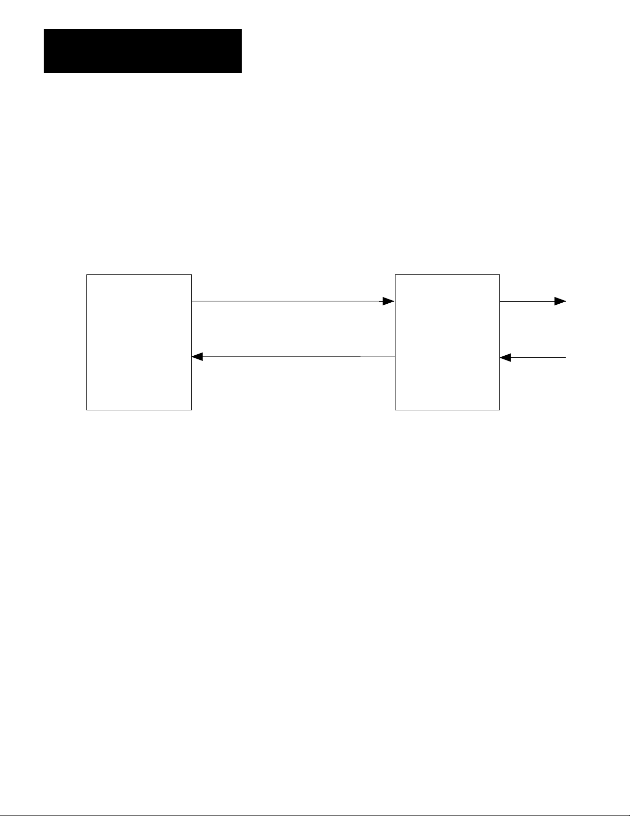
Figure 4.2 shows where the servo positioning assembly fits in a PC
system. The PC processor constantly communicates with the servo
12005
41
Page 26
Chapter 4
Positioning with Allen-Bradley PC
positioning assembly through the I/O scan. The PC processor acts on a
block transfer read instruction to receive status blocks. Based on the
status information received, the PC processor acts on a block transfer
write instruction to send either parameter blocks, move blocks, or control
blocks.
Figure 4.2
the Servo Positioning Assembly Fits in a PC System
Where
PC
Processor
Independent of I/O Scan
Move/Moveset
Output Scan
Parameter, Moveset, and Command Blocks
Input Scan
Status Blocks
Servo
Positioning
Assembly
Outputs
Inputs
12006
Although the servo positioning assembly sends data to and receives data
from the data table through the I/O scan, the positioning loop is closed on
the 1771-ES expander (at the positioning loop summing point). This
allows the 1771-ES expander to provide a servo sample period of 2.4ms,
independent of I/O scan.
You must describe the axis motion you want in moveset blocks in the data
table. You can enter a maximum of 21 separate move blocks in a moveset
block (Figure 4.3).
42
Page 27
Chapter 4
Positioning with Allen-Bradley PC
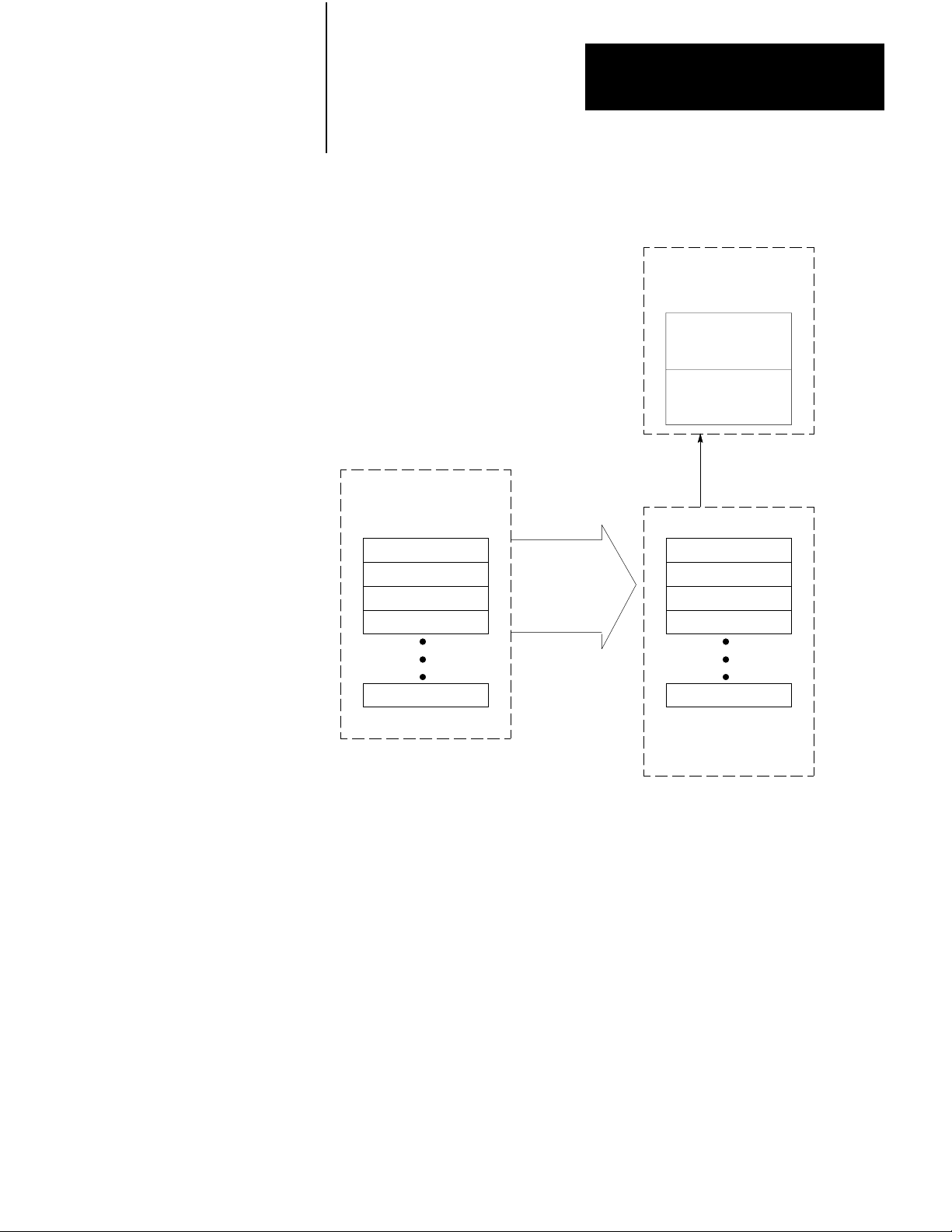
Figure 4.3
Moveset Block is Sent to the 1771M3 Controller That Sends the Move Blocks Sequentially
A
to the 1771ES Expander
TwoMoveBlock
register in the
1771-ES expander
Current
Move
Next Move
Move blocks sent in sequence
as each current move is started.
Moveset block in
the PC Processor
data table
Move 1
Move 2
Move 3
Move 4
Move 21
A
complete moveset (21
moves max) is sent in a
single block transfer
.
Move 1
Move 2
Move 3
Move 4
Move 21
Moveset register
in the 1771-M3
controller
12007
The PC processor sends a complete moveset block to the 1771-M3
controller in a single block transfer. The 1771-M3 controller can hold a
moveset block for each of the three possible axes.
The 1771-ES expander can hold two move blocks, the current move block
available for execution and the next move block. After the current move
is completed and the next move is to be executed, the next move block
becomes the current move block (Figure 4.4).
43
Page 28
Chapter 4
Positioning with Allen-Bradley PC
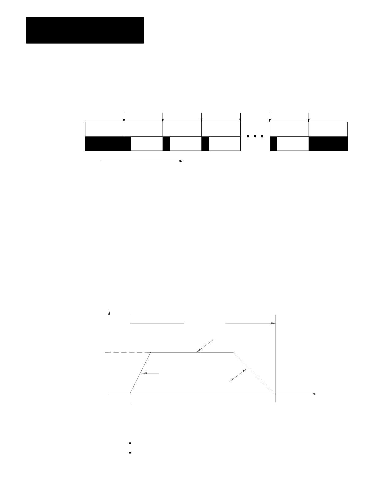
Figure 4.4
the 1771ES Expander, as Each Current Move is Completed, the Next Move Block is
In
Ready to T
ake its Place
Current Move Block
Next Move Block
Start
of
Move
Move 1 Move 1 Move 2 Move 3 Move 20 Move 21
Move Move 2 Move 3 Move 4 Move 21 Move
Time
Start
of
Move
Start
of
Move
Start
of
Move
Start
of
Move
Start
of
Move
Initially, the 1771-M3 controller sends the first move block to the
1771-ES expander. Then, as each move is started the 1771-M3 controller
sequentially sends each of the remaining move blocks to the 1771-ES
expander.
A move block for a move to position defines motion of the axis from one
position to another. Figure 4.5 shows the profile of an axis move. The
horizontal axis in the figure represents axis position. The vertical axis
represents axis velocity. Moves plotted above the position axis are in the
positive direction (from left to right), moves plotted below the position
axis are in the negative direction (right to left).
12008
44
Rate +
Final Velocity
or Feedrate
Figure 4.5
Onemove
0
Startpoint
Profile for an Axis
Acceleration
Move
Constant
Velocity
Deceleration
Endpoint
Position
11010
In the move shown in Figure 4.5, the axis:
starts from a resting position
accelerates to a final velocity
Page 29
Chapter 4
Positioning with Allen-Bradley PC
moves at the final velocity some distance
decelerates to zero velocity (at which time it has reached the
programmed endpoint)
Move Values
Each move block can specify several values. The servo positioning
assembly executes the move based on these items you enter:
endpoint
acceleration
final feedrate
deceleration
When you select a deceleration value, the 1771-ES expander
automatically calculates the point at which the deceleration must begin.
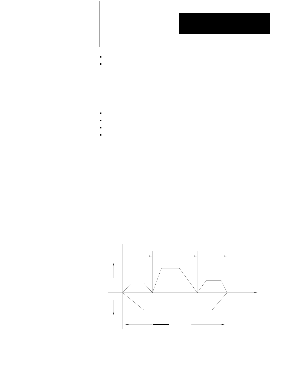
You can combine several single moves like that of Figure 4.5 to form a
moveset. Figure 4.6 shows an example that consists of four moves.
Move 1 starts at position coordinate 0 and ends at position coordinate 2.
Move 2 continues axis motion to position coordinate 5. Move 3 continues
to position coordinate 7. Move 4 then causes the axis to reverse direction
and move back to position 0. The axis stops after it returns to its initial
starting position. A drawing like that of Figure 4.6 is a moveset profile.
You can use such profiles as an aid in programming axis motion.
Figure 4.6
Moveset
Rate +
Profile with All Singlestep Moves
Move 1 Move 2 Move 3
0
12345 678
Position
Rate
Move 4
11011
45
Page 30

Chapter 4
Positioning with Allen-Bradley PC
You can program multiple movesets for a given axis.
Move Selection
For each move, you have each of the following selections:
Absolute or incremental positioning - In an absolute move, the
endpoint value specifies a position coordinate relative to the current
axis zero position. In an incremental move, the endpoint value
specifies a position coordinate relative to the last programmed endpoint
achieved by the axis.
Global or local values - You enter a global final feedrate value and a
global accel/decel rate value. These global rates apply to all moves
except those for which you select to specify local rates. A local rate
applies only to a single move.
Halt or run - After completing a move for which you have selected
halt, the 1771-ES expander will not execute the next move until it
receives a begin or start command. After completing a move for which
you have selected run, the 1771-ES expander will immediately execute
the next move without waiting for a start command. With halt selected,
the module executes a single-step move. With run selected, you can
select moves to be either single-step moves or continuous moves.
Single-step or continuous - When the 1771-ES expander executes a
single-step move, it decelerates the axis to zero velocity at the
programmed endpoint. When it executes a continuous move, it
attempts to blend the move smoothly with the final feedrate of the next
move (if the next move is in the same direction). The moves in
Figure 4.6 are all programmed as single-step moves. Figure 4.7 shows
the same moveset with all moves programmed as continuous. A
moveset can contain a mix of single-step and continuous moves.
46
Page 31

Chapter 4
Positioning with Allen-Bradley PC
Figure 4.7
Moveset
Profile with all Continuous Moves
Move 1 Move 2
Rate +
0
Rate
1
2
Move 3
3456
Move 4
Position
7
11012
Move Alternatives
In place of a move to position, in any move block you can select one of
the following:
8
11012
Dwell - Instead of an endpoint and rates, you can program a time in
seconds in the move block. When the 1771-ES expander executes a
dwell move block, it stops axis motion for the programmed amount of
time.
Preset to Position - You can program an axis position preset value in
the command block. When the 1771-ES expander executes a preset to
position, it sets its axis position register to the programmed preset
value. No axis motion occurs.
Move to Position with Offset - The parameter block contains an offset
value. When the 1771-ES expander executes a move to position with
offset, it adds this offset value to an offset accumulator. For every
move, it adds the value stored in the accumulator to the programmed
endpoint then executes the move.
Constant Velocity - This command clears the position register to zero
before moving the axis to the position you specify. By repeatedly
generating continuous constant velocity moves, you can cause
uninterrupted motion, which could, for example, be applied to a
conveyor.(Figure 4.8).
47
Page 32

Chapter 4
Positioning with Allen-Bradley PC
Rate +
In Position
Figure 4.8
Moveset
0
Profile for Constant V
elocity Moves
Position
12009
For a continuous move with the next move in the same direction, the
move is complete when the axis feed is done. The 1771-ES expander
immediately begins the feedrate for the next move without waiting for the
following error to close.
Synchronizing Axes
For any halt move, single-step move, or a continuous move with the next
move in the opposite direction, the move is not complete until the axis is
in position. The axis is in position when the following conditions are met:
the axis feed is done
following error has closed to within the in-position band
You establish the in-position band in the parameter block. The in-position
band is the largest distance from the endpoint at which you will allow the
axis to be considered in position.
In many applications it is important to synchronize the motion of two or
more axes. In the following sections, we will tell you how to do this.
Halt Moves
For halt moves, axis synchronization is straightforward. When an axis is
in position after a move, the next axis move will not begin until you send
a start command.
48
Page 33

Chapter 4
Positioning with Allen-Bradley PC
You can monitor the in-position signal of each axis through the status
block. When all axes are in position, you can send a start command to
each axis through the command block.
Alternatively, you can monitor the in-position signal of each axis through
the hardware done output terminal of the 1771-ES expander. When all
axes are in position, you can send a start command to each axis through
the hardware start input terminal of the 1771-ES expander.
Using the hardware start and done signals is faster than using block
transfer for the status and command blocks. Furthermore, if the axis
synchronization includes multiple servo positioning assemblies, precise
synchronization cannot occur through block transfer because two block
transfers cannot occur simultaneously.
Continuous Moves
For continuous moves with the next move in the same direction, axis
synchronization requires precise programming of feedrates, acceleration
rates, and deceleration rates. You must program the move blocks so that
each axis takes the same amount of time for corresponding moves.
Furthermore, you must plan the moves to be long enough to adhere to the
following constraints:
Each move must take longer than the time it takes to transfer a move
block from the 1771-M3 controller to the 1771-ES expander. This time
is a function of the number of axes as follows:
No.
of Axes
1 20ms
2 25ms
3 30ms
Time
If the number of moves requires additional moveset blocks, the last two
moves of each preceding moveset block must not be too short. They
must take a long enough time for the following moveset block to be
transferred from the data table. (Refer to chapter 8 for details about
block transfer timing.)
49
Page 34

Chapter 4
Positioning with Allen-Bradley PC
RunSingleStep Moves
For run-single-step moves, axis synchronization is dependent upon the
axis response on each move. The same is true for continuous moves with
the next move in the opposite direction.
In both cases, the 1771-ES expander executes the next move
automatically as soon as the current move is done, without waiting for a
start signal. However, the time it takes for each move cannot be precisely
calculated because the following error has to close before the move is
done.
Auto Position Correction
The auto position correction feature may prevent an accumulation of
position error caused by occasional noise on the channel A and B inputs.
However, if the environment is excessively noisy, or if the cabling and
shielding is not proper, this feature causes the axis to jump or jerk. This
jump or jerk should indicate to you that a problem exists.
Specifying Axis Position
You enter the number of lines on the encoder and the feedback multiplier
into the parameter block. From this, the 1771-ES expander knows how
many feedback pulses it should receive each encoder revolution. The
module also receives a marker pulse each revolution.
Each time the 1771-ES expander receives a marker pulse, it checks the
value in the position register to see if it is an even multiple of the number
of feedback pulses per revolution. If the value is off, the 1771-ES
expander will automatically adjust it.
This feature corrects position errors caused by noise on the channel A and
B encoder feedback signals. However, the function of this feature
assumes a noise-free marker signal.
The marker signal does have some noise protection because the 1771-ES
expander only accepts a marker signal when the channel A and B signals
are high (unless you set the marker logic jumper to the not-gated
position).
To command axis motion, you must be able to specify axis position by
establishing an axis position scale, or coordinate system, for each axis.
410
Page 35

Chapter 4
Positioning with Allen-Bradley PC
Figure 4.9 shows an example of an axis and its position scale. Any axis
position within the range of travel can be identified by a number. For the
servo positioning assembly, the axis position scale can be either in inches
or millimeters.
The position scale is an internal scale used by the servo positioning
assembly to identify axis position. It is not printed on the axis slide. You
can shift the axis position scale by entering (through the command block)
any of the following commands:
search home
preset
initialize home
Figure 4.9
Position Scale
Axis
INCHES
0
10 20 30 40 50 60 70 80 90 100 110 120 130 140 150MM
21 3 4 5 6
17967
Search Home
Because the position feedback is incremental rather than absolute, the
servo positioning assembly does not know the axis position when it first
receives power. You must command a search home (through the
command block) each time after powering up. In the search home
operation, the axis moves until the servo positioning assembly detects the
first encoder marker beyond the user-installed home limit switch. The
411
Page 36

Chapter 4
Positioning with Allen-Bradley PC
axis stops on the marker. The servo positioning assembly then sets it
position register to the home position value you specify in the parameter
block. This initializes the axis position scale. Figure 4.10 shows how the
home position value you specify in the parameter block can affect the axis
position scale. This figure compares the scales for an axis after search
home operations with different home position values form the parameter
block representing the same physical position.
Figure 4.10
Position Scales for 2 Home Position V
Axis
Home
alues
2 0
10
3.00
5.00
+9 Parameter Block Home
Position Value=3.00
0+1
Parameter Block Home
Position Value5.00
11008
Preset
Through a command block, you can command the servo positioning
assembly to preset a specified value into its position register. When the
servo positioning assembly executes a preset command, it sets its position
register to the specified value without causing axis motion. This action
effectively shifts the axis position scale. Figure 4.11 shows an axis
position scale before and after a preset operation.
Figure 4.11
Position Scale before and after Preset
Axis
412
5 0
5 0 +5
1.5 +5
After Preset (1.5)
Before Preset
11009
Page 37

Chapter 4
Positioning with Allen-Bradley PC
Initialize Home
Through a command block you can generate an initialize home command.
The initialize home operation assigns the home position value (which you
specify in the parameter block) to the current axis position. Its effect is
the same as that of the preset operation, except that the new position value
is the home position value.
Summary
Now that you have been familiarized with the general concepts of how the
servo positioning assembly functions in a closed-loop positioning system
and in a PC system, you are ready for specific details of the servo
positioning assembly in chapter 5.
413
Page 38

Hardware Description
Chapter
5
Chapter Objectives
Indicators
The previous chapter described how the servo positioning assembly fits
into a positioning system as part of a programmable controller. This
chapter describes specific hardware of the servo positioning assembly and
lists its specifications. This chapter also describes other hardware items
you need for a positioning system.
There are three indicators on the 1771-M3 controller. With the PC
processor operating in the run mode, the indicators have the following
functions:
Processor Communication Fault - This red indicator turns on
when the module detects a fault in the communication
between it and the PC processor. The I/O adapter module or
PC processor will not detect this as a fault.
Expander Communication Fault - This red indicator turns on
when the module detects a fault in the communication
between it and a 1771-ES expander.
Active - This green indicator is normally on. It turns off
when a hardware fault is detected on a 1771-ES expander. it
blinks if you have not properly configured the modules.
There are six indicators on the 1771-ES expander. With the PC processor
operating in the run mode, the indicators have the following functions:
Module Active - This green indicator is on when the module
is operating normally.
Marker - This green indicator is on when the channel A,
channel B, and marker signals are true simultaneously.
Home - This green indicator is on when the axis is in the
home position.
Tach Calibrate - This green indicator is used in setting the
adjustments for loss of feedback detection.
Hardware Stop - This red indicator goes on when the
hardware stop input opens. It stays on until the input closes
and the servo expander module is reset.
Diagnostic - This red indicator goes on when a fault is
detected at the servo expander module.
51
Page 39

Chapter 5
Hardware Description
These indicators are useful troubleshooting aids, described fully in chapter
9.
Inputs/Outputs
The 1771-M3 controller requires no connections. You will make all
wiring connections to the 1771-ES expander. Figure 5.1 shows the
terminals on the 1771-ES expander. These terminals provide the
connection points for all the inputs and outputs of the servo positioning
assembly. Limit the cable length to 50 feet for all connections.
Figure 5.1
Terminals
On the 1771ES Expander Showing Input and Output Signals
52
1 Input Supply (+ 5 to 30V dc )
2ChannelA
3 Channel A
4 Channel B
5ChannelB
6Marker
7Marker
8 Jog Forward (HDW Start)
9 Jog Reverse (FDRT ENBL)
10 Home Limit Switch
11 Hardware Stop
12 + 5to 30V d c Common
2
3
4
5
6
7
8
9
10
11
12
1 Analog Supply (+15V dc )
2 Not Used
3 Analog Output
4 Analog Return
+
5 15V DC Common
-
6 Analog Supply (- 15V d c)
7 (HDW Done)
8 Drive Disable Supply
9 Drive Disable Output
10 Drive Disable Common
11 Tachometer
12 Tachometer
12010
Page 40

Chapter 5
Hardware Description
Outputs to Servo Drive
Terminals 3 and 4 on the right wiring arm provide connection points for
the velocity command signal to the serve drive. This analog output is a
+10V dc differential signal.
Terminals 8, 9, and 10 on the right wiring arm provide connection points
for a drive disable signal (Figure 5.2). In chapter 6 we will show you how
to connect this output to either source or sink 100mA maximum to enable
the drive. The module normally provides current thru this transistor to
enable the drive. However, the module will turn off the current to disable
the drive if:
the hardware stop input goes high
a command block commands an immediate stop
a firm ware or hardware watchdog timers times out
the 1771-ES expander detects excess following error, a loss of
feedback, or a power supply loss
Figure 5.2
Schematic
1771-ES Expander
Diagram of the Drivedisable Output Circuit
Ω
8.2k
8
9
Q1
10
8
9
10
DRIVE
DISABLE
SUPPLY
DRIVE
DISABLE
OUTPUT
DRIVE
DISABLE
COMMON
12011
The 1772-ES expander is compatible with a wide variety of servo drives,
including Allen-Bradley Bulletin dc Servo Controllers (refer to
publication 1388 -5.0). Allen Bradley also offers Bulletin 1326 dc servo
Motors to match the Bulletin 1388 dc Servo Controllers.
53
Page 41

Chapter 5
Hardware Description
Tachometer Input
Terminals 11 and 12 on the right wiring arm provide connection points for
the velocity feedback signal from the tachometer. Although the velocity
loop is closed on the servo drive, the 1771-ES expander uses the velocity
feedback signal to compare to the position feedback signal from the
encoder. If the module detects an imbalance between these signals, it
disables the servo drive and sends a loss of feedback signal through the
status block.
The 1771-ES expander accepts a full scale tachometer signal of 3V to
50V dc. If the full scale tachometer signal is greater than 50V dc, you
must reduce it through a voltage divider on the servo drive before
connecting it to the module.
CAUTION: Do not connect a signal greater than 50V dc across
these terminals. A signal greater than 50V dc could damage the
1771-ES expander.
Hardware Done Output
Terminal 7 on the right wiring arm provides a connection point for a
hardware done output signal (Figure 5.3).
54
Page 42

Chapter 5
Hardware Description
1771-ES Expander
1kΩ
Figure 5.3
Schematic
Diagram of the Hardwaredone Output Cirucit
1
2
3
4
5
6
1
2
3
4
5
6
7
7
ANALOG SUPPLY
(+15Vdc)
NOT USED
ANALOG
OUTPUT
ANALOG
RETURN
+15Vdc
-
COMMON
ANALOG SUPPLY
(-15Vdc)
(HDW DONE)
12012
The output transistor, normally on, provides a 15mA (maximum) sink.
When the axis feed is done and the axis is in position, the transistor is off
and the circuit provides +15V dc through a 1k resistor. This provides you
with a hardware done signal that is high-true.
In chapter 6, we will show you how to connect the hardware done signal
to a dc (12-24V) Input Module (cat. no. 1771-IB) for axis synchronization
of halt moves.
Discrete Inputs
Terminals 8, 9, 10, and 11 on the left wiring arm provide connection
points for discrete input signals. The module accepts a discrete input
signal as being high when it reaches 40% of the input power supply
voltage. The module accepts a discrete input signal as being low when it
reaches 20% of the input power supply voltage.
55
Page 43

Chapter 5
Hardware Description
Each discrete input has an internal pull-up resistor. In chapter 6, we will
show you how to select an internal pull-up resistor of 1.2k or 11.2k. You
select each input individually through a switch setting.
For a high signal, the input device you connect to a discrete input does not
have to source current. For a low signal, the input device you connect to a
discrete input has to sink current through the pull-up resistor.
Hardware Start
In the auto mode, the module accepts a high-to-low transition at terminal
8 of the left wiring arm as a low-true hardware start input signal.
After completing a halt move, the 1771-ES expander will not execute the
next move until it receives a start command. The start command could
come through block transfer of a control block or through the hardware
start signal.
Feedrate Override Enable
In the auto mode, the module accepts a high-to-low transition at terminal
9 of the left wiring arm as a low-true feedrate override enable signal.
After setting a feedrate override value for the axis through the command
block and enabling external synchronization of feedrate override through
the parameter block, you can enable the feedrate override through this
input. Do this by setting bit 16 of word 17 in the parameter block ON
(Axis 1). (Set bit 16 of words 36 and 55 for axis 2 and 3, respectively.).
This allows you to activate a preloaded feedrate override value to change
speed on several axes at the same instant.
Jog Forward
In the manual mode, the module accepts the signal at terminal 8 of the left
wiring arm as a low-true jog forward signal. When the module receives
this signal, it moves the axis in the positive direction at the rate
established through block transfer.
56
Page 44

Chapter 5
Hardware Description
Jog Reverse
In the manual mode, the module accepts the signal at terminal 9 of the left
wiring arm as a low-true jog reverse signal. When the module receives
this signal, it moves the axis in the negative direction at the rate
established through block transfer.
Home
The module accepts the signal at terminal 10 of the left wiring arm as a
low-true home signal. The module considers the first marker pulse after
the home signal as the home position.
Hardware Stop
The module accepts the signal at terminal 11 of the left wiring arm as a
high-true hardware stop signal. Unless this input is pulled low, the
module holds the velocity command output signal at zero and disables the
servo drive by turning off the drive disable circuit.
Encoder Inputs
Terminals 2, 3, 4, 5, 6, and 7 on the left wiring arm provide connection
points for input signals from the encoder. Through jumpers on the
module, you can select each channel individually for either single-ended
or differential, and for either high-true of low-true input signals.
If you use a single-ended encoder, limit the input pulse rate to 20k Hz. If
you use a differential encoder, limit the input pulse rate to 250k Hz.
The 1771-ES expander is compatible with Allen-Bradley Incremental
Differential Line Driver Encoders (cat. no. 845N-SJDN4-C) and with
other encoders having current-sinking (5-30V dc) line-driver outputs,
totem-pole (TTL) outputs, or open-collector outputs.
External Power Supplies
You must provide at least two external dc power supplies to provide
power for the input and output circuits.
57
Page 45

Chapter 5
Hardware Description
Input Supply
You must connect a 5-30V dc power supply between terminals 1 and 12
of the left wiring arm. This provides power for the input circuits. The
input circuits require 500mA (maximum) at 30V. You can use the same
power supply to power the encoder if the power supply has enough
additional current capacity for the encoder.
Drive Disable Supply
Unless the servo drive provides its own dc voltage source for this circuit,
you’ll need a 5 - 30V dc power supply to provide 100mA (maximum) for
the drive disable circuit. How you connect this power supply depends on
whether the servo drive requires a current source or a current sink to
enable it.
Compatible Processors
Analog Supply
A separate +15V dc supply is needed to provide 200mA (maximum) for
the digital/analog converter (DAC) to generate the analog output signal
and for the hardware done output circuit.
The servo positioning assembly can be used with PC processors that have
block transfer capability and adequate data table size to contain the data
blocks you need for your application. Compatible PC processors include:
Mini-PLC-2/05 (cat. no. 1772-LS,-LSP)
Mini-PLC-2/15 (cat. no. 1772-LV)
PLC-2/20 (cat. no. 1772-LP2)
PLC-2/30 (cat. no. 1772-LP3)
PLC-3 (cat. no 1775-L1,-L2)
58
Page 46

Chapter 5
Hardware Description
Fault Responses
The servo positioning assembly provides a means for detecting and
responding to faults in your servo positioning system.
Since the servo positioning assembly is part of a PC system, diagnostic
information about fault conditions detected by the servo positioning
assembly can be block transferred to the PC processor.
At the PC processor, you can use the ladder diagram program to respond
to diagnostic information about fault conditions in any way you feel is
appropriate for your application. This may include turning off machinery,
turning on alarms, or generating report printouts. Furthermore, with an
Allen-Bradley Data Highway network, you can send this diagnostic
information to a computer or other Allen-Bradley PC processors.
The servo positioning assembly provides specific fault responses if certain
critical connections are broken.
Loss of Feedback
The 1771-ES expander continuously monitors the tachometer and encoder
feedback. If it senses an imbalance between these signals, it holds the
velocity command output signal at zero and disables the servo drive
through the drive disable circuit. Therefore, if the cable from either the
encoder or the tachometer breaks, the 1771-ES expander will disable the
servo drive.
Hardware Stop
You must connect a set of normally open contacts of your master control
relay between the hardware stop input terminal and the input power
supply common terminal. Normally, the master control relay would be
energized, pulling the hardware stop input low. This allows the module to
enable the servo drive.
However, if the master control relay de-energizes for any reason (such as
extreme overtravel limit or emergency stop), the hardware stop input goes
high. This forces the module to hold the velocity command output signal
at zero and disable the servo drive by turning off the drive disable circuit.
Therefore, if a connection in the hardware stop circuit breaks, the
1771-ES expander will disable the servo drive.
59
Page 47

Chapter 5
Hardware Description
Loss of Power
The 1771-ES expander holds the velocity command output signal at zero
and disables the servo drive by turning off the drive disable circuit if it is
unable to sense the specified voltage as the following power-supply
terminals:
positive (+) terminal for the input power supply
common (-) terminal for the input power supply
positive (+) terminal for the analog power supply
negative (-) terminal for the analog power supply
Therefore, if one of these power supplies connected to the 1771-ES
expander terminal fails or if one of these connections from these power
supply breaks, the 1771-ES expander will disable the servo drive.
The drive disable circuit normally provides current to a sensing circuit on
the servo drive to enable it. However, if the 1771-ES expander detects a
fault, it cuts off the current in the drive disable circuit, thereby disabling
the servo drive. Therefore, if a connection in the drive disable circuit
breaks, this disconnection will disable the servo drive.
Auto Position Correction
Each time the 1771-ES expander receives a marker pulse, it checks the
value in the position register to see if it is an even multiple of the number
of feedback increments per revolution. If the value is off, the 1771-ES
expander will automatically adjust it to the closest even multiple.
This auto position correction feature corrects position errors caused by
noise on the channel A and B encoder feedback signals. However, the
function of this feature assumes a noise-free marker signal. Although this
feature may be able to prevent an accumulation of position error caused
by occasional noise on the channel A and B inputs, it cannot maintain
position accuracy if the environment is excessively noisy or if the cabling
and shielding is not proper.
510
If the environment is excessively noisy or if the cabling and shielding is
not proper, this feature will cause the axis to jump or jerk. This jump or
jerk indicates a problem.
Note that when the module detects a position error, it does not necessarily
disable the servo drive.
Page 48

Chapter 5
Hardware Description
Because this feature adjusts the position register to the closest even
multiple of the number of feedback increments per revolution, it is
essential that the axis move less than half an encoder revolution per servo
sample period (2.4ms). Therefore, to avoid a programming error, you
must limit the axis speed to conform to this formula:
Specifications
programmed
axis speed
<
12,500
1.28
x FR x FM x EL
Where:
FR = feedback resolution
FM = feedback multiplier (1, 2, or 4)
EL = encoder lines per revolution
Here is a list of specifications for the servo positioning assembly.
Servo Output Voltage
+10V dc maximum (isolated)
D/A Converter (DAC)
Signed 12 bit resolution
Encoder Input
High: 1.6V
Low: 1.0V sinking lmA
Encoder Input Rate
Differential: 250k Hz maximum
Single-ended: 20k Hz maximum
Jumper selection of differential or single ended input
Encoder Multiplier
x1, x2, or x 4,programmable
Tachometer Input (For loss-of-feedback detection)
Full scale voltage: 3V dc minimum, 50V dc maximum
Input impedance: 20k ohmss
Discrete Inputs
511
Page 49

Chapter 5
Hardware Description
Resistance to high side of supply 11.2k ohms or 1.2k ohms, switch
selectable for each input
For a low, required sink current with 1.2k ohms resistance: 4mA @ 5V,
24mA @ 30V
For a low, required sink current with 11.2k ohms resistance: 0.4mA @
5V, 2.7mA @ 30V
High: 40% of + dc supply voltage
low: 20% of + dc supply voltage
Hardware Done Output
On: +15V source thru 1k ohms resistance
Off: 15mA sink
Drive Disable Output
Current: 100mA maximum, source or sink
Voltage: 30V dc maximum to 5V dc minimum
Backplane Current
1771-M3 controller: 1.75A
1771-ES expander: 1.70A
External Power Supply Requirements
External supply for inputs, +4.75 dc minimum, +30V dc maximum,
500mA maximum
External supply for DAC and hardware done output, +15V dc, 200mA
maximum
External supply for drive disable output, +4.75V dc minimum, +30V dc
maximum, 100mA maximum
Maximum Programmable Position
+999.9999 inches (resolution 0.0001 inch)
+19999.999 millimeters (resolution 0.001 mm)
Programmable Speed
512
0.0001-9990.0000 ipm (resolution 0.0001 ipm)
0.001-199900.000 mmpm (resolution 0.001 mmpm)
Accel/Decel
9999 ipm/s maximum (resolution 1 ipm/s)
99.99 mpm/s maximum (resolution 0.01 mpm/s)
Initial Servo Gain (Programmable)
Page 50

Chapter 5
Hardware Description
0.01-9.99 ipm/mil following error (1 mil = .001 inch)
0.01-9.99 mmpm/mil following error (1 mil x .001 mm)
Servo Sample Period
2.4ms
Environmental Conditions
Operational Temperature: 0o to 60oC (32o to 140oF)
Storage Temperature: -40o to 85oC (-40o to 185oF)
Relative Humidity: 5% to 95% (without condensation)
Keying
Servo controller slot: between 2 and 4, 8 and 10
Left servo expander slot: between 2 and 4, 14 and 16
Right servo expander slot: between 4 and 6, 32 and 34
Summary
Now that you have read about the function of each input and each output,
you are ready to install the servo positioning assembly. Chapter 6 gives
you this information.
513
Page 51

Installing the Assembly
Chapter
6
Chapter Objectives
Configuring the Modules
The previous chapter described the hardware of the servo positioning
assembly. This chapter tells you how to install the servo positioning
assembly. As you install it, you will make hardware selections to direct its
operation to fit your application requirements.
The first step of installing a servo positioning assembly is to plan how to
configure modules in the I/O chassis.
Planning Module Combinations
You can install one 1771-M3 controller in an I/O chassis together with
either one, two, or three 1771-ES expanders. However, the I/O chassis
must not contain any other module combination of a master (such as an
analog module) and its slave (expander).
A master must communicate with its slaves through the backplane. Two
masters trying to communicate through the backplane interferes with each
other.
If you have an illegal combination of 1771-ES expanders or a second
master/slave combination in the I/O chassis, the active indicator on the
1771-M3 controller blinks. An illegal combination of 1771-ES expanders
would be:
the number of 1771-ES expanders not matching the number of axes in
the parameter block
an axis 2 with no axis 1
an axis 3 with no axis 2
two axes with the same number
Always use the same series level of 1771-M3 controller and 1771-ES
expander. You cannot use a series A 1771-M3 controller with a series B
1771-ES expander. Likewise, you cannot use a series B 1771-M3
controller with a series A 1771-ES expander.
61
Page 52

Chapter 6
Installing the Assembly
Avoiding Backplane Power Supply Overload
For each module you plan to install in the I/O chassis, add up it current
load on the backplane power supply. Be sure that this total current is not
so large as to overload the backplane power supply.
The backplane power supply current load of the servo positioning
assembly is:
1771M3
controller
1 1 3.45A
1 2 5.15A
1 3 6.85A
1771ES
expanders
Total
Current
Note that if you add the total current draw of one 1771-M3 controller,
three 1771-ES expanders, and either an I/O adapter or mini-processor
module, the total would exceed 8A. In that case you could not use a
1771-P1 or 1771-P2 power supply because they are rated at 6.5A.
If the total current exceeds 6.5A, you can use Power-Supply Modules (cat.
no. 1771-P3, -P4, -P5) to provide 8A, 11A or 16A. The following table
lists the number of axes you can control with a servo positioning system
in a 1771-A4 I/O chassis, based on power requirements and compatibility
of other components used with the 1771-A4 I/O chassis.
I/O
Adapter or MiniProcessor Module Cat. No.
62
Power
Supply
Cat. No.
1771P1
1771P2
1771P3
1771P4
1771P4 plus
1771P3 or
a second
1771P4
1771AL 1771AS 1772LS 1772LSP 1771LV
1 Axis
2 Axes 2 Axes
2 Axes 1 Axis
3 Axes 3 Axes 3 Axes
3 Axes 3 Axes
Page 53
Chapter 6
Installing the Assembly
Planning Module Location
The 1771-M3 controller requires one I/O chassis slot. You can install it in
any I/O in the I/O chassis. The 1771-M3 controller uses both the output
image table byte and the input image table byte that correspond to its
location address.
The 1771-ES expander requires two slots. Install it in a pair of slots that
make up an I/O module group.
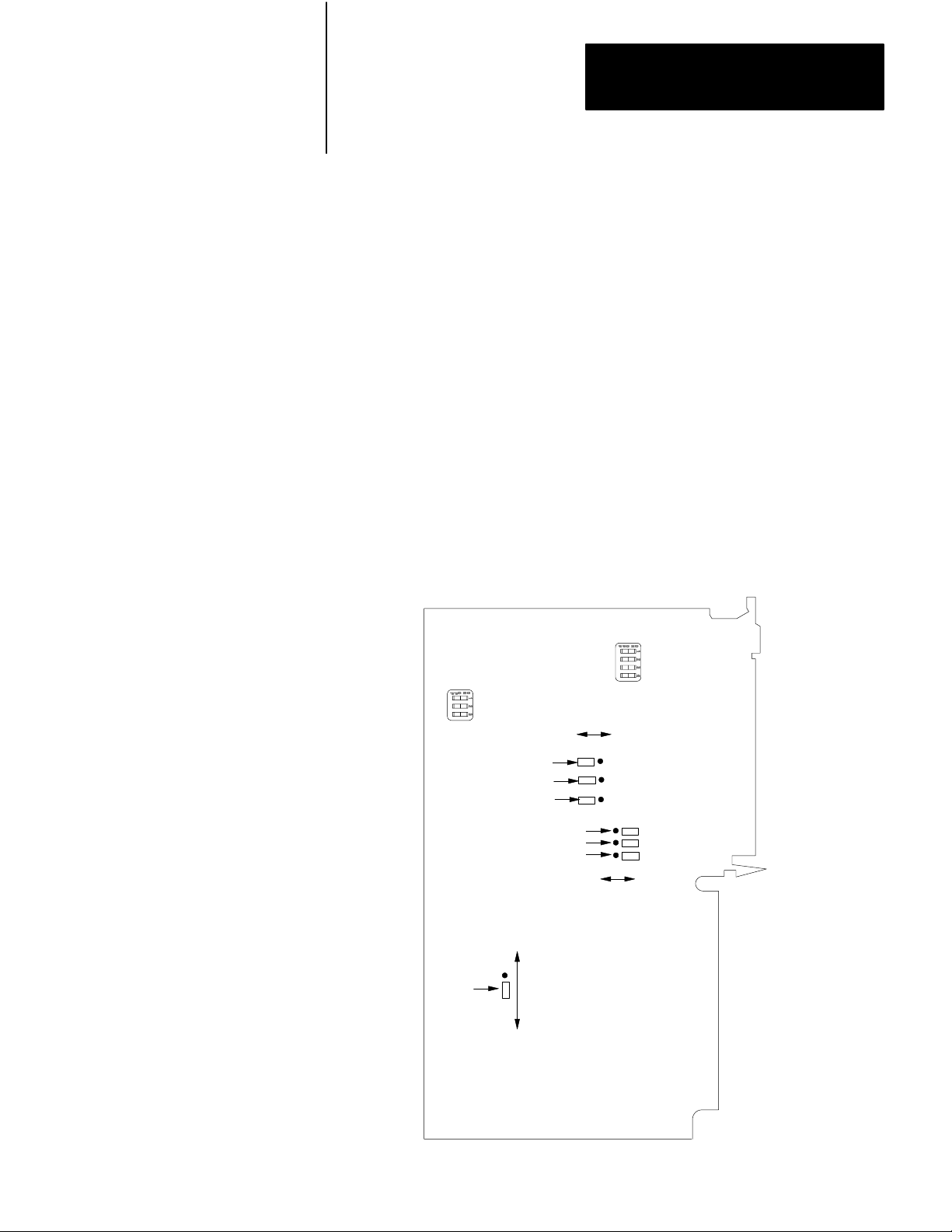
Setting Switches and Jumpers
Through switches and jumpers on the 1771-ES expander, you can select
various aspects of the module’s operation. To access these switches and
jumpers, lay the 1771-ES expander on its right side and remove the left
cover. Locate the switches and jumpers through Figure 6.1.
Figure 6.1
1771ES
Expander Switches and Jumpers
Discrete Input Resistance
Switch Assembly
Axis Number
Switch Assembly
High -True
CH A Polarity Jumper
CH B Polarity Jumper
Marker Polarity Jumper
CH A Signal Mode Jumper
CH B Signal Mode Jumper
Marker Signal Mode Jumper
Single -Ended
Low -True
Differential
Not Gated
Marker
Logic
Jumper
GatedwithCHAandCHB
12013
63
Page 54

Chapter 6
Installing the Assembly
This publication shows and describes switches as being on or off. Printed
on the actual switch assemblies are the words ON and OFF or the word
OPEN. OPEN corresponds to OFF.
Use a blunt-pointed instrument such as a ball-point pen to set these
switches. Never use a pencil; graphite could jam the switch.
Figure 6.2 shows details of a jumper connecting two pins. Each jumper
connects two of a set of three pins. To change a jumper setting, follow
these steps:
1. Pull the jumper straight up.
2. Position the jumper over the pins you want to connect.
3. Push the jumper straight down.
If you position the jumper correctly, it slides down over the pins easily.
Figure 6.2
in the Left Position
Jumper
12014
64
Page 55

Chapter 6
Installing the Assembly
Selecting Discrete Input Resistance
Select the resistance between each discrete input terminal and the high
side of the input power supply. To select 1.2k ohms, set the switch on. To
select 11.2k ohms, set the switch off. (Figure 6.3)
Figure 6.3
Discreteinputresistance
Hardware
Stop
Switch Assembly
Jog Forward
(hardware start)
Jog Reverse
(feedrate enable)
Home Limit
Switch
1234
O
N
O
F
F
ON
OFF
ON
OFF
ON
ON - 1.2k
(pull - up) resistance
OFF - 11.2k
(pull - up) resistance
OFF
Ω
input
input
Ω
12015
With 1.2k ohms, your input device must sink 4mA for a 5V power supply
to 25mA for a 30V power supply. With 11.2k ohms, your input device
must sink 0.5mA for a 5V power supply to 2.7mA for a 30V power
supply.
Unless your input device cannot sink enough current, select 1.2k ohms
because it provides better noise immunity than an 11.2k ohms input
resistance.
65
Page 56

Chapter 6
Installing the Assembly
Selecting Axis Number
Select the axis number as shown in Figure 6.4.
Figure 6.4
Axisnumber
Switch Assembly
Axis1
Axis2
123
O
N
O
F
F
Axis3
ON
OFF
ON
OFF
ON
SetoneswitchtoON
toselectthataxisnumber.
Settheother
twotoOFF.
OFF
12016
Set to on the switch corresponding to the number for the axis. Set to off
the other two switches in the assembly. Set each 1771-ES expander in an
I/O chassis to a unique axis number, starting with 1.
66
Selecting Encoder Input Polarity
Select the polarity of each encoder input to allow your encoder to function
properly with the 1771-ES expander (Figure 6.1).
Encoder Polarity Jumper Position
High-true
Low-True
Left
Right
•
•
Page 57

Chapter 6
Installing the Assembly
With a differential encoder, the connections and the polarity jumper
positions determine the polarity of the feedback signals. With a
single-ended encoder, the polarity jumper positions alone determine the
polarity of the feedback signals.
The polarity selections are important to the marker logic. Set the polarity
so that the marker is true at the same time that channels A and B are true
(refer to Figure 3.7)
Selecting Encoder Input Signal Mode
Select the signal mode of each encoder input to match the encoder
(Figure 6.1).
Encoder Signal Mode Jumper Position
Single-ended
Differential
Left
Right
•
•
•
•
•
•
Selecting Marker Logic
For almost all encoders, set the marker logic jumper to the bottom
position to gate the marker with channel A and channel B. This gives the
marker signal a level of noise immunity.
However, if you cannot select the polarity so that the marker on your
encoder is always true at the same time as the channel A and B signals, set
the market logic jumper to the top position.
Keying
A package of plastic Keys (cat. no. 1771-RK) is provided as standard with
each I/O chassis. When properly installed, these keys can guard against
the seating of all but a selected type of module in a particular I/O chassis
module slot. Keys also help align the module with the backplane
connector.
67
Page 58

Chapter 6
Installing the Assembly
Each module is slotted at the rear edge. Position the keys on the chassis
backplane connector to correspond to these slots to allow the seating of
the module.
Insert keys into the upper backplane connectors. Position the keys
between the numbers at the right of the connectors. Refer to Figure 6.5
for the 1771-M3 controller keying position. Refer to Figure 6.6 for the
1771-ES expander keying positions.
Figure 6.5
Diagram for the 1771M3 Controller
Keying
Keying
Bands
Between
•
pins 2 and 4
pins 8 and 10
•
2
4
6
8
10
12
14
16
18
20
22
24
26
28
30
32
34
36
11005
68
Page 59

Figure 6.6
Keying Diagram for the 1771ES Expander
Upper Left Upper Right
Connector Connector
Chapter 6
Installing the Assembly
Inserting the Module
Keying
Bands
Between
•
pins 2 and 4
pins 14 and 16
•
2
4
6
8
10
12
14
16
18
20
22
24
26
28
30
32
34
36
2
4
6
8
10
12
14
16
18
20
22
24
26
28
30
32
34
36
Between
•
pins 4 and 6
pins 32 and 34
•
11006
To insert a module into an I/O chassis, follow these steps:
1. Remove power from the I/O chassis before inserting or removing a
module.
2. Open the module locking latch on the I/O chassis and insert the
module into the slot keyed for it.
3. Press the module firmly to seat it into its backplane connector.
4. Secure the module in place with the module locking latch.
CAUTION: Do not force a module into a backplane connector;
if you cannot seat a module with firm pressure, check the
alignment and keying. Forcing a module can damage the
backplane connector or the module.
69
Page 60

Chapter 6
Installing the Assembly
Connecting to Terminals
5 to 30V DC
Belden 8761 or
equivalent
(50 ft max)
4
TTL
Output
Encoder
Input Power
Supply
(customer
supplied)
-
Belden #8725 or
equivalent
(50ft. max.)
JOG FWD
JOG REV
+
1
2
HOME LS
Hardware STO P
Make connections to the 1771-ES expander as shown in Figure 6.7.
Figure 6.7
Simplified
CH. A
CH. A
CH. B
CH. B
Marker
Marker
I/O T
erminal Connection Diagram
Belden 8723 or
equivalent (50ft max)
+
15V dc
For DAC
(Customer
Supplied)
+ Comm -
Belden #8761 or
equivalent
(50ft. max.)
To Servo
Motor
+
10V
Unused
Command
Servo
Return
3
Drive
(Customer
Supplied)
6
Drive Disable
High
Low
7
5
-+
5 to 30V dc Drive
Disable Supply
(Customer
Supplied)
Tach
+
-
610
Belden 8761 or
NOTES:
equivalent (50ft. max.)
If equipment permits, one supply can be used for encoder and input circuits. Current requirements depend on hardware configuration.
1
In the auto mode, the modul e accepts this input as the hardware start si gnal (figure 6.9).
2
In the auto mode, the modul e accepts this input as the f eedrate enable signal (figure 6.9).
3
The module generates a hardware done signal at this +15V dc driver output terminal (figure 6.12).
4
Refer to figures 6.10 and 6.11.
Refer to figure 6.8.
5
6
Refer to figures 6.13 and 6.14.
7
Refer to figure 6.15.
12017
Page 61

Chapter 6
Installing the Assembly
This is a simplified diagram to give you an overall view of how you are to
connect these terminals. We give you further details in the following
sections and their associated figures. For all connections to the terminals,
limit the cable length to 50 feet.
Keep low-level conductors separate from high-level conductors. This is
particularly important for cable connections to the encoder. Follow the
practices outlined in the PC Grounding and Wiring Guidelines
(publication 1770-980).
Power Supplies
Use shielded cable for connecting the input power supply and the analog
power supply. Route these cables only with low-level conductors. Keep
these power supply cables as short as possible. Ground the common
terminal for each of these power supplies.
Encoder and Tachometer
For an encoder or tachometer connection, use only a single, continuous,
shielded cable segment. Do not break the cable for connection in a
junction box. Connect the cable directly from the encoder to the 1771-ES
expander.
Important: Ensure that the power supply for the encoder provides the
voltage recommended by the encoder manufacturers.
Shielded Cables
For many connections, we tell you to use shielded cable. Using shielded
cables and properly connecting their shields to ground protects against
electromagnetic noise interfering with the signals transmitted through the
cables.
WARNING:Use shielded cable where we tell you to use it and
how we tell you to use it. If you do not, the axis motion in your
positioning system could be unpredictable; this could result in
damage to equipment and/or injury to personnel.
611
Page 62
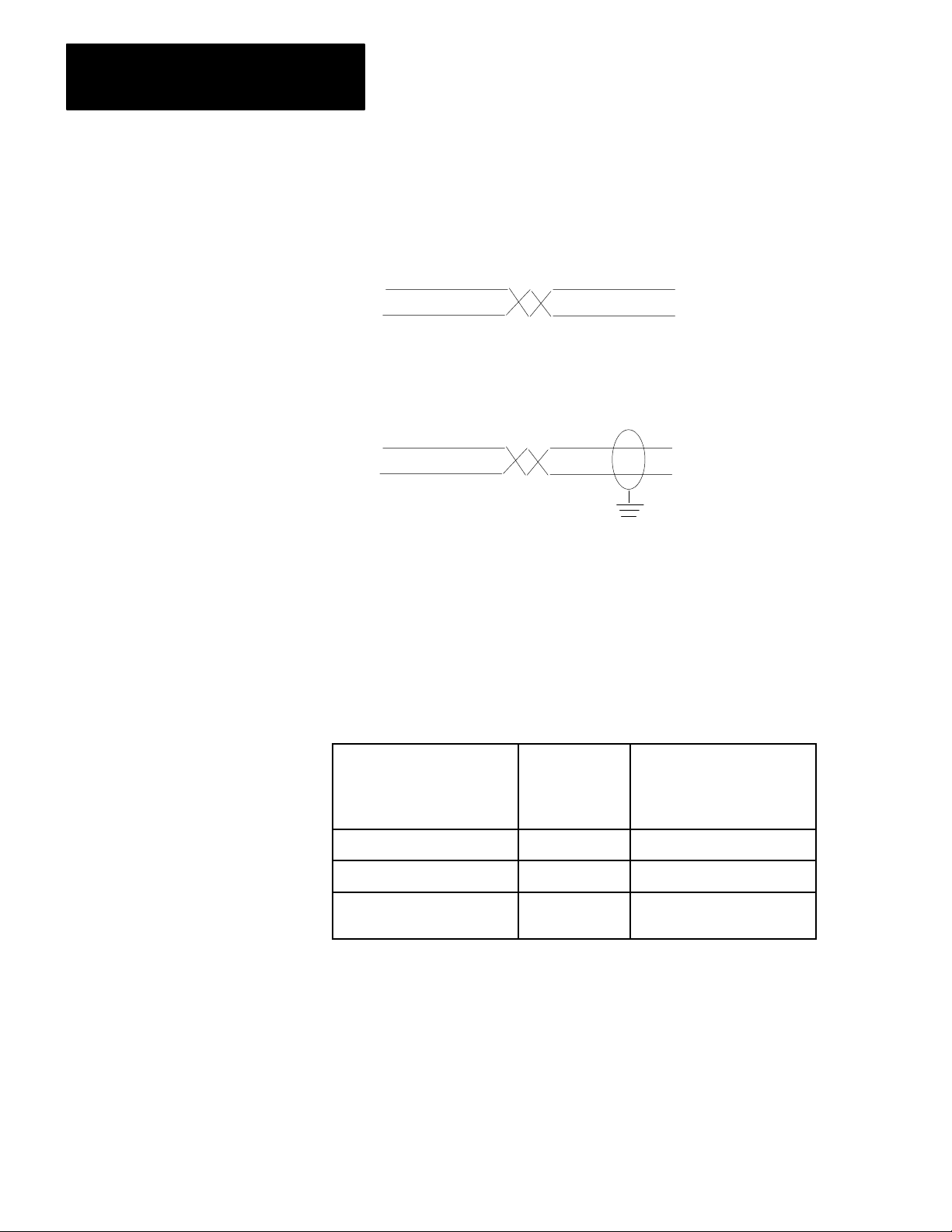
Chapter 6
Installing the Assembly
Within a shielded cable, pairs of wires are twisted together. Using a
twisted pair for a signal and its return path provides further protection
against noise. We show a twisted pair like this:
We show a shielded twisted pair like this:
.
Connect each shield to ground at one end only. At the other end, cut the
shield foil and drain wire short and cover them with tape to protect against
their accidentally touching ground. Keep the length of leads extending
beyond the shield as short as possible.
Use cables with the proper number of individually shielded twisted pairs
as follows:
Number of
Individually
Shielded
To
connect to:
Encoder 4
Analog power supply
All other shielded cable
connections
T
wisted Pairs:
2
1
Use:
Belden 8725 or equivalent
Belden 8723 or equivalent
Belden 8761 or equivalent
Connecting the Input Supply
612
To connect the input power supply, follow these steps:
1. Connect the plus side of the input power supply to terminal 1 of the
left wiring arm.
Page 63

Chapter 6
Installing the Assembly
2. Connect the minus side to terminal 12 and to ground at the I/O
chassis.
3. Connect the shields of the two cable segments if you use the same
supply to power the encoder.
4. Connect the shield to ground at the I/O chassis end.
5. Connect the power-supply chassis to ground.
Connecting Hardware Stop
Before you connect to the hardware stop input, you should first consider
overall power distribution, including the master-control relay and
loop-contactor relay (Figure 6.8). Connect a suppression network across
each relay coil.
613
Page 64

Chapter 6
Installing the Assembly
H
1
X
F
u
s
e
Extreme
Overtravel
Limit Switches
Use any number
of E - stop switches
in series
Figure 6.8
Simplified
Hardware Stop
H
4
H
H
3
2
Isolation/
Step Down
Transformer
X
12
CRM
Reset
LCR
Power Distribution with the MasterControl Relay, Loopcontactor Relay
Incoming
AC
Disconnect
CRM
CRM
LCR
L
L
1
F
u
s
e
L
3
2
F
F
u
u
s
s
e
e
Isolation/
H
1
H
3
H
4
H
2
Step Down
Transformer
F
u
s
e
F
u
s
e
Servo Drive
1
Dynamic
LCR LCR
Braking
Resistor
LCR
, and
614
Backplane
1
Power Supply
Power Supply for
Analog Output Circuit
-15V DC
Common
+15V dc
Power Supply for
Input Circuits
CRM
+5 - 30V dc
CRM
To Input CircuitsTo I/O Modules
NOTE:
To minimize EM generation, connect a suppression network for 120V ac, AllenBradley
1
cat. no. 700N24; fo r220/240V ac. Electrocube part no. RG 167613 .
CRM
Servo Xformer
Thermal Overload
Servo Drive
Fault
Servo Motor
Thermal Overload
Servo
Motor
11
1771 - ES Expander
12
Hardware
Stop
+5 - 30V dc
Common
12018
Page 65

Chapter 6
Installing the Assembly
Provide one transformer for the master-control relay (CRM) circuit, the
loop-contactor relay (LCR) circuit, the dc power supplies, and any ac I/O
chassis. Provide a separate transformer for the servo drives to provide
noise immunity.
Use normally-open LCR contacts to switch power from the servo drive to
the servo motor. Also, use normally closed LCR contacts to switch in the
dynamic braking resistor across the servo motor whenever power is
removed from the servo motor. Check with the servo drive and servo
motor manufacturer for the resistance and power rating for the dynamic
braking resistor.
WARNING:Without a dynamic braking resistor, removing
servo motor power while the axis is in motion allows
momentum to keep the axis in motion. In an emergency
situation, this could be dangerous. A dynamic braking resistor
can help stop the servo motor by quickly dissipating the energy
of momentum. Even with dynamic braking, a vertical axis may
also require an electric brake or counter balance.
An extreme overtravel limit switch or an emergency stop switch can
de-energize the LCR, thereby turning off servo motor power. However,
abruptly stopping an axis in this way stresses the servo motor and the
mechanical linkage. Therefore, use the LCR to stop a moving axis only in
an emergency. To stop an axis in a non-emergency situation, use the
slide-stop bit in the command block thru the ladder diagram program. A
slide stop decelerates the axis feedrate before stopping it. After a slide
stop you can use an emergency stop switch if you want to remove power.
Connect a set of normally-open CRM contacts in series with servo
transformer overload, servo drive fault, and servo motor overload
contacts. Connect this series of contacts between the hardware stop input
terminal and common. The opening of any of these contacts indicates that
power to the servo motor is interrupted. When any of these sets of
contacts open the hardware stop circuit, the following occur:
1. When this circuit opens, the 1771-ES expander immediately sets the
velocity command output to zero and disables the serve drive by
turning off the drive disable circuit.
615
Page 66

Chapter 6
Installing the Assembly
2. The 1771-M3 controller sends the hardware stop signal to the PC
data table thru the status block transfer.
3. After this circuit closes again, the 1771-ES expander still holds the
velocity command at zero and holds the servo drive disabled until
you either:
send a reset signal through a command block transfer (This allows
the 1771-ES controller to maintain the accumulated axis position.)
cycle I/O chassis backplane power off, then back on (This clears
the accumulated axis position.)
When you restart the axis after a hardware stop, the axis feedrate
accelerates before reaching the final velocity rate. This allows a smooth
start-up after a hardware stop.
Do not provide switch contacts in the hardware stop circuit for an
operator to turn off the axis motion. Opening the hardware stop circuit
stops the axis abruptly, stressing the servo drive, the servo motor, and the
mechanical linkage, just as the CRM would. Use the hardware stop input
only for backup to inform the 1771-ES expander of a condition that has
already stopped the axis so that the expander can provide a controlled
start-up.
Connecting Home Limit Switch
To connect a home limit switch, follow these steps:
1. Connect a normally open limit switch between the home limit switch
terminal and common.
2. Place the limit switch so that it closes as the axis reaches a point
approximately one half of an encoder revolution from the point you
want to establish as home position.
3. Adjust the angular position of the encoder to have the marker pulse
occur precisely at the point you want to establish as home position.
616
Through the command block transfer you can command a search home
function (sections titled “Axis Control Word” and “Axis Control Word
2”). The 1771-ES expander:
moves the axis to the limit switch
decelerates the axis
Page 67

Chapter 6
Installing the Assembly
establishes the point of the next marker pulse following the limit switch
as the home position
stops the axis at the home position
You must re-establish the home position after each time power to the I/O
chassis backplane goes off, because the encoder feedback is incremental, .
Connecting Jog Reverse (Feedrate Override Enable)
Figure 6.9 shows details of how to connect jog reverse and feedrate
override enable. Follow these steps:
1. Provide a 3-pole selector switch to select between auto and manual
mode.
2. Connect one pole of the selector switch to a discrete input module
terminal. Use this input to control the auto/manual bit in the control
block. This bit controls whether the 1771-ES expander is in the auto
or manual mode.
3. Connect a second pole of the selector switch to the jog reverse
(feedrate override enable) terminal of the 1771-ES expander.
4. Connect a momentary-contact jog reverse switch to the selector
switch contact corresponding to manual on the second pole.
5. Connect a momentary-contact feedrate override switch to the selector
switch contact corresponding to auto on the second pole.
617
Page 68

Chapter 6
Installing the Assembly
Figure 6.9
Connection
Enable)
10
11
12
Details for Jog Forward (Hardware Start) and Jog Reverse (Feedrate Override
3-Pole
Selector
Switch
(Auto)
(Manual)
(Auto)
(Manual)
Discrete input module
terminal to control
the auto/manual bit
in the command block.
5 to 30V dc
Input Power
Supply
(customer
supplied)
-
+
10
11
12
1
2
3
4
5
6
7
8
9
1
2
3
4
5
6
7
8
9
Auto
Manual
To other axes
Hardware Start
Jog
Forward
Feedrate
Override Enable
Jog
Reverse
618
Wiring Arm of
1771 - OZ Contact
Output Module
Left Wiring Arm
of 1771 - ES Expander
12019
In the manual mode, the jog reverse switch controls whether the input is
high or low. In the auto mode, the feedrate override enable switch
controls whether the input is high or low. You can connect the same
feedrate override enable signal to several 1771-ES expanders to
coordinate the start of feedrate override for those axes.
Connecting Jog Forward (Hardware Start)
Figure 6.9 also shows details of how to connect jog forward and hardware
start. Follow these steps:
Page 69

Chapter 6
Installing the Assembly
1. Connect a third pole of the selector switch to the jog forward
(hardware start) terminal of the 1771-ES expander.
2. Connect a momentary-contact jog forward switch to the selector
switch contact corresponding to manual on the third pole.
3. Connect an output terminal of a Contact Output Module (cat. no.
1771-OZ) to the selector switch contact corresponding to auto on the
third pole.
In the manual mode, the jog forward switch controls whether the input is
high or low. In the auto mode, the hardware start output from the
1771-OZ module controls whether the input is high or low.
You can use the ladder diagram program to generate a hardware start
signal (by closing the contacts of 1771-OZ module output) when each of
several axes generates a hardware done signal. You can connect the same
hardware start signal to several 1771-ES expanders to coordinate the start
of motion following halt moves for these axes.
Connecting a Differential Encoder
Figure 6.10 shows details of how to connect a differential encoder. With a
differential encoder, reversing the connections on a channel or changing
the position of the polarity jumper for the channel reverses the polarity of
the signal on that channel. Set the polarity so that the marker is true at the
same time that channels A and B are true.
If you switch channel A with channel B, you reverse the direction of the
feedback. If the direction of the feedback does not correspond to the axis
motion direction, as you have defined it, switch channel A with channel
B.
Ground the shield at the I/O chassis end.
619
Page 70

Chapter 6
Installing the Assembly
Figure 6.10
Connection
Details for a Differential Encoder
5to30VDC
Belden8761or
equivalent
(50ftmax)
Differential
Output
Encoder
Belden8725or
equivalent
(50ftmax)
InputPower
Supply
(customer
supplied)
CHA
CHA
CHB
CHB
Marker
Marker
Groundtheshield
attheI/Ochassisend
Groundtheshield
attheI/Ochassisend
1
2
3
4
5
6
7
8
9
10
11
12
620
LeftWiringArm
of1771-ESExpander
12020
Connecting a SingleEnded Encoder
Figure 6.11 shows details of how to connect a single-ended encoder.
Connect each channel return line to common.
Page 71

Chapter 6
Installing the Assembly
Figure 6.11
Connection
Details for a Singleended Encoder
5 to 30V DC
Belden 8761 or
equivalent
(50 ft max)
Single - Ended
Output
Encoder
Belden 8725 or
equivalent
(50 ft max)
Input Power
Supply
(customer
supplied)
Ground the shield
at the I/O chassis end
CH A
CH A
CH B
CH B
Marker
Marker
Ground the shield
at the I/O chassis end
1
2
3
4
5
6
7
8
9
10
11
12
Left Wiring Arm
of 1771 - ES Expander
12021
If you switch channel A with channel B, you reverse the direction of the
feedback. If the direction of the feedback does not correspond to the axis
motion direction, as you have defined it, switch channel A with channel
B.
Ground the shield at the I/O chassis end.
Connecting the Analog Output Supply
To connect the analog output supply, follow these steps:
1. Connect the plus (+) side of the analog and hardware one output
power supply to terminal 1 of the right wiring arm.
2. Connect the minus (-) side to terminal 6.
621
Page 72

Chapter 6
Installing the Assembly
3. Connect the common to terminal 5.
4. Connect the shield to ground at the I/O chassis.
Connecting Velocity Command
Connect the analog velocity command output signal from terminals 3 and
4 on the right wiring arm to the corresponding terminals of the servo
drive. Reversing these connections reverses the direction the axis moves
in response to the velocity command. Connect this signal so that the
direction of motion that results from it matches the correct direction of
motion as you have defined it.
Connect the shield to ground at the servo drive end.
622
Page 73

Chapter 6
Installing the Assembly
Connecting Hardware Done
Figure 6.12 shows details of how to connect hardware done. Follow these
steps:
Figure 6.12
Connection
Right Wiring Arm
of 1771 - ES Expander
1
2
3
4
5
6
7
8
9
10
11
12
Details for Hardware Done Output
+
15V dc
-
For DAC
(customer supplied)
+
Comm
-
+15V
-15V
Belden 8761 or
equivalent
(50ft max)
Hardware Done
Wiring Arm of
1771 - IB Input Module
A
0
1
2
3
4
5
6
7
8
12022
1. Connect the hardware done output from terminal 7 on the right
wiring arm to an input terminal of a dc (12-24V) Input Module (cat.
no. 1771-IB).
2. Connect the analog and hardware done output power supply common
to the 1771-IB input module common terminal. This power supply
provides the +15V dc source for the hardware done signal.
Examine the hardware done signal thru the ladder diagram program. You
can synchronize the motion of several axes after each halt move: send a
hardware start signal to all axes when you have received the hardware
done signal from each axis.
623
Page 74

Chapter 6
Installing the Assembly
Connecting Drive Disable
Figure 6.13 shows details of how to connect drive disable for two basic
types of configurations. Some servo drives require a current source
connected to an input to enable the drive. Some require a current sink
connected to an input to enable the drive. We provide all three connection
points (base, emitter, and collector) of the drive disable circuit to provide
you with a flexibility of connecting it in a configuration that applies to
your servo drive.
a) Current Sourcing Configuration
Drive Enable Q1 on: Current is sourced
from terminal 10 into the servo drive.
Drive Disabled Q1 off: Current into the
servo drive is inhibited.
b) Current Sinking Configuration
Drive Enable Q1 on: Current is sunk thru
terminal 9 and Q1.
Drive Disabled Q1 off: Current thru Q1 is
inhibited. Terminal 9 is pulled up to the
potential of terminal 8.
Figure 6.13
Connection
Drive Disable
Input on Customer's
Servo Drive
Details for Two Basic Drive Configurations
8
8.2k
9
Q1
10
8
8.2k
9
Q1
Drive Disable
Input on Customer's
Servo Drive
10
+
Customer's Drive
Disable Power Supply
-
(5 to 30V dc)
+
Customer's Drive
Disable Power Supply
-
(5 to 30Vdc)
12023
624
For the drive disable circuit, you must provide a 5-30V dc power supply
which can provide 100mA maximum. The power supply can be separate
or an integral part of the servo drive. Each of the configurations of figure
6.13 includes a separate power supply.
Page 75

Chapter 6
Installing the Assembly
Figure 6.13a shows a current sourcing configuration. Normally the drive
disable circuit is on, sourcing current into the drive thru terminal 10.
When the drive disable circuit turns off, the drive is disabled.
Figure 6.13b shows a current sinking configuration. Normally the drive
disable circuit is on, sinking current from the drive thru terminal 9. When
the drive disable circuit turns off, the drive is disabled.
Figure 6.14 shows how to connect the drive disable circuit to the Bulletin
1388 servo drive which has an internal power supply and requires a
current source to enable it.
8
8.2k
9
Q1
10
Right Wiring Arm of
1771ES Expander
Figure 6.14
Connection
Details for Providing a Drive-disable Signal to the Bulletin 1388 Servo Drive
12
+
-
13
Bulletin 1388
Servo Drive
12024
Note that whatever configuration your drive requires, you must connect
the plus side of the power supply to terminal 8 on the right wiring arm of
the 1771-ES expander. Without this connection, the drive disable circuit
will not turn on; the 1771-ES expander will not enable the servo drive.
625
Page 76

Chapter 6
Installing the Assembly
Connecting the Tachometer
Figure 6.15 shows details of how to connect the tachometer. Follow these
steps:
Figure 6.15
Connection
Right Wiring Arm
of 1771 - ES Expander
Details for T
1
2
3
4
5
6
7
8
9
10
11
12
50V Max
at Terminals
achometer
High
Low
27K
Servo Drive
Ω
High
(+)
Low
(-)
Tach
12025
626
1. Connect the tachometer directly to the servo drive.
2. Connect the tachometer signal at the servo drive to the right wiring
arm of the 1771-ES expander. This allows the 1771-ES expander to
detect loss of tachometer feedback at the servo drive. Limit the
voltage at the terminals to 50V maximum. Tachometers typically
generate much larger voltages than 50V at high speed. Therefore,
you must drop the voltage thru a voltage divider.
3. Unless you have access to a voltage divider in the servo drive, place
a 27k ohms 1/4 Watt potentiometer between the servo drive and
terminal 11 of the 1771-ES expander.
4. Set the potentiometer for maximum resistance until you perform the
integration procedures (chapter 9).
Page 77

Chapter 6
Installing the Assembly
5. Connect the tachometer high signal to terminal 11.
6. Connect the tachometer low signal to terminal 12.
7. Connect the shields of the cable segments.
8. Connect the shield to ground at the I/O chassis end.
Connecting AB Encoder and
Drive
Figure 6.1 shows the jumpers in the position in which we place them for
shipping the 1771-ES expander to you. These channel polarity jumper
settings select high-true polarity. These channel signal mode jumper
settings select differential mode. This marker logic jumper setting selects
the marker to be gated with channel A and channel B. If you use the
Allen-Bradley 845N-SJDN4-C encoder, leave the jumpers set to the
position shown in Figure 6.1.
With the jumpers set as shown in figure 1, connect the 845N-SJDN 4-C
encoder to the 1771-ES expander as shown in Figure 6.16. We show the
channel A signal connection reversed with the not channel A connection
and the channel B signal connection reversed with the not channel B
connection. This inversion of the channel A and B polarity allows the
marker to be high at a time when both channels A and B are high.
Use an 8 to 15V dc power supply for the input circuits. Connect the plus
side of the supply voltage to pin E of the encoder. With this
configuration, 5V dc power is generated at the encoder; the signals from
the encoder are 5V dc.
627
Page 78

Chapter 6
Installing the Assembly
Cat. no. 845N SJDN4 - C Encoder
H
G
A
I
B
J
F
C
D
E
8 to 15V dc
Power Supply
for Input
Circuits
(customer
supplied)
+
1
Figure 6.16
Connections
Drive
-
CRM
to a Cat. No. 845NSJDN4C Encoder and a Bulletin 1388 dc Servo Controller
1771 - ES
Expander
11
A3TB1
10
9
7
6
8
Bulletin 1388
12
DC Servo
13
Controller
5
Drive
4
3
1
2
15
14
Motor
2
27K
2
Tach
NOTES:
1
Belden 8725 or equivalent 50ft max)
2
Belden 8761 or equivalent (50ft max)
P1
P2
P1
P2
Bulletin 1388
Power
Transformer
12303
Connect the bulletin 1388 dc servo controller drive and its bulletin 1388
power transformer to the 1771-ES expander as shown in Figure 6.16.
Tachometer input terminal 12 on the 1771-ES expander and terminal 2 on
the drive each connect to a dc common at ground potential; therefore, you
must connect these terminals directly as shown.
Connect the analog output signal from terminal 3 of the 1771-ES
expander to terminal 7 of the drive. Connect the analog return signal from
terminal 4 of the 1771-ES expander to terminals 6 and 8 of the drive.
With this signal orientation, when you connect the tachometer to the drive
with the proper polarity for negative feedback, the signal will also have
628
Page 79

Chapter 6
Installing the Assembly
the proper polarity for loss-of-feedback detection at the 1771-ES
expander. If you use the opposite analog output signal orientation, you
will not be able to utilize the loss-of-feedback detection feature.
WARNING: Always utilize the loss-of-feedback feature.
Without loss-of-feedback detection, if encoder or tachometer
feedback is lost, unexpected axis motion can occur, resulting in
damage to equipment and/or injury to personnel.
Limit the cable lengths to 50 feet. If your application requires a cable
length greater than 50 feet, contact your local Allen-Bradley
representative.
Grounding Cable Shields
Figure 6.17 is a pictorial representation of the shielded cable connections.
Mount a ground bus directly below the I/O chassis to provide a
connection point for cable shield drain wires and the common connections
for the input circuits. Connect the I/O chassis ground bus through 8 AWG
wire to the central ground bus to provide a continuous path to ground.
The tachometer cable is broken into three segments because of the
connection to the drive and potentiometer in the middle of the cable.
Connect these cable shield segments together as shown. Connect the
shield to ground only at the I/O chassis end. Do not connect the shield to
the drive.
629
Page 80

Chapter 6
Installing the Assembly
8to15V dc
PowerSupply
forinput
Circuts
(customer
supplied)
Shieldedcablesarenot
requiredforthesediscrete
inputs.However,theycan
improvenoiseimmunity.
Figure 6.17
Shielded
1771-ES
Expander
1
1
Cable Grounding Connections
+ 15V dc
For DAC
(Customer Supplied)
+ Return-
2
27K
1
Drive Disable
3
Motor
Twistedpair
withshield
orconduit
Bulletin1388
DCServo
Controller
Drive
1
Tach
NOTES:
1
Belden8761orequivalent.
2
Belden8723orequivalent.
3
Belden8725orequivalent.
8AWGwireto
central ground bus
I/OChassis
GroundBus
Encoder
12304
Connecting AC Power
Figure 6.18 shows ac power connections. Incoming ac connects to the
primary of the bulletin 1388 power transformer. Both the 120V secondary
and the 35.5V secondary connect to the bulletin 1388 dc servo controller
drive.
Incoming ac also connects to the primary of an isolation transformer. The
secondary of the isolation transformer connects to:
the power supply for the input circuits
the power supply for the I/O chassis backplane
the power supply for the analog output circuit
Figure 6.18 shows a grounded ac system; the low side of the isolation
transformer is connected to the central ground bus. Figure 6.18 also
630
Page 81

Incoming
AC
Chapter 6
Installing the Assembly
shows connections from the central ground bus to each chassis and to the
I/O chassis ground bus shown in Figure 6.17.
Figure 6.18
Power and Ground Connections
AC
120V AC
Fuse
H1H2H3H4
Isolation
Transformer
X1 X2
L1 N
Power
Supply
for Input
Circuits
H7H4H1
Bulletin 1388
Central
Ground Bus
G
L1 N
G
Power
Supply for
I/O Chassis
Backplane
G
I/O Chassis
Ground Bus
L1 N
+
15V dc
For DAC
(Customer
Supplied)
+ Return -
G
Power
Transformer
Y2Y3Y1
35.5V ac
120V AC
X1
X2
X3
A3TB1 A2TB1
11
10
9
G
789
Bulletin 1388
DC Servo
Controller
Drive
A2TB1
45
Motor
Startup Sequence
17966
After properly installing your servo positioning assembly, formatting the
data blocks, entering the program, and integrating each axis, you start up
the system in the following sequence.
1. De-energize the CRM relay.
631
Page 82

Chapter 6
Installing the Assembly
2. Turn on the dc power connected to the wiring arms.
3. Turn on the power supply for the I/O chassis backplane.
4. Energize the CRM relay.
5. Generate a reset command through the command block.
Summary
Now that you have installed the servo positioning assembly, you are ready
to enter data blocks into the data table of the PC processor. During
installation you made hardware selections to direct module operation. In
chapter 7, we tell you how to make software selections to direct other
aspects of module operation.
632
Page 83

Chapter
7
Formatting and Interpreting Data Blocks
Chapter Objectives
Relationship of Data Blocks
The previous chapter told you how to install the modules. During
installation, you made hardware selections through switch and jumper
settings. These hardware selections direct some aspects of module
operation.
This chapter tells you how to make software selections through data
blocks you set up in the data table. Through data blocks you direct
module operation.
This chapter also tells you how to monitor module operation through a
data block that the module sends to the data table.
You must program the PC processor to communicate with the 1771-M3
controller through a block-transfer-read instruction and a
block-transfer-write instruction. The data blocks are:
status block
parameter block
moveset block
command block
The block-transfer-read instruction transfers status block data from the
1771-M3 controller to the data table. The block-transfer-write instruction
transfers the parameter block, the moveset block, and the command block
data from the data table to the module. (Figure 7.1).
71
Page 84

Chapter 7
Formatting and Interpreting Data Blocks
Figure 7.1
The Status Block Transfers to the Data T
Blocks go to the 1771M3 Controller
able the Parameter
, Moveset, and Command
Data Table
Status
Block
Parameter
Block
Moveset
Block
Command
Block
Block Transfer Read
Block Transfer Write
1771-M3
Controller
Status
Block
Parameter
Block
Moveset
Block
Command
Block
12029
72
Status Block
The status block is regularly transferred to the data table to provide
updated information about the current status of each axis. This status
includes:
actual axis position
in position
at home position
slide stop
emergency stop
software travel limit exceeded
feed reduction
excess following error
auto/manual mode
address pointer to tell the program which block (parameter, moveset, or
control) to write transfer to the 1771-M3 controller next
diagnostic status that tells you where programming errors are in
parameter, moveset, and command blocks
Page 85

Chapter 7
Formatting and Interpreting Data Blocks
The first block transfer after power-up writes a 6-word status block into
the data table. After that, the status block consists of 6 words for a 1-axis
system, 10 words for a 2-axis system, or 14 words for a 3-axis system.
You establish the address for the status block through the block transfer
read instruction. Because axis command and status data is stored in the
data table, axis motion control can interact with other axes, discrete I/O,
and report generation.
Parameter Block
The parameter block for a 1-axis system has 25 words; a 2-axis system
has 44 words; a 3-axis system has 63 words.
You specify parameters for each axis separately. You specify parameters
such as:
software travel limits
home position
servo gain
global accel/decel rate
rapid traverse rate
In the parameter block, you also specify the address of the parameter
block, the command block, and the first moveset block for each axis.
With these addresses, the 1771-M3 controller can ask (through the status
block) for the block it needs at any particular time.
The processor transfers the parameter block to the 1771-M3 controller
through a block transfer write. This provides axis parameter information
after a power-up and after a command block commands a reset or new
parameters.
Moveset Block
A moveset block describes a sequence of axis moves. You can program
axis motion to provide either single-step moves or continuous moves.
Each move requires a minimum of three words (a single-move control
word and two words to define position or dwell time) and can include
three optional words (a rate word, an accel word, and a decel word) for a
total of six. A moveset control word applies to the entire block. If
additional moveset blocks are needed, you also need a next-moveset-point
word. A moveset block can be 64 words long maximum and describe 21
moves maximum. To describe 21 moves in a single moveset block, all 21
73
Page 86

Chapter 7
Formatting and Interpreting Data Blocks
moves would have to use the global accel/decel and final rate values from
the parameter block.
Upon request from the status block, the PC processor sends a moveset
block to the 1771-M3 controller, which transfers each move description to
the 1771-ES expander one at a time. The 1771-ES expander generates the
analog voltage to command axis motion as programmed.
Command Block
The command block for a 1-axis system has up to four words; a 2-axis
system has up to eight words; a 3-axis system has up to 12 words. This
block regularly transfers from the data table to provide commands (such
as start, slide stop, search home, jog, reset and offset) for each axis unless
the 1771-M3 controller needs a parameter or moveset block. You must
include the command block address in the parameter block.
Status Block
Data Table Allocation
You must allocate a sufficiently large data table area for the data blocks
needed in the block transfer communication. Furthermore, the parameter
block must start at least 63 words before the end of a contiguous data
table area. Also, each moveset block (regardless of size) must start at
least 64 words before the end of a contiguous data table area. For a
PLC-2 family processor, assign data block addresses of 200 or greater to
avoid processor work areas.
The status block, which is the only block transferred from the 1771-M3
controller to the processor, contains information about axis and servo
positioning assembly status. The first block transfer after power-up writes
a 6-word status block into the data table. After that, the status block
consists of word assignments (Figure 7.2):
Size of
Number
of Axes
1
2
3
Status Block
6 words
10 words
14 words
74
Page 87

Figure 7.2
Status Block Showing W
Chapter 7
Formatting and Interpreting Data Blocks
ord Assignments
Word
1
Future Use
2
Address Pointer
3
Status Word 1 (Axis 1)
4
Status Word 2 (Axis 1)
5
(MS) Position/FE/Diagnostic (Axis 1)
6
(LS) Position/FE/Diagnostic (Axis 1)
7
Status Word 1 (Axis 2
8
Status Word 2 (Axis 2)
9
(MS) Position/FE/Diagnostic (Axis 2)
10
(LS) Position/FE/Diagnostic (Axis 2)
11
Status Word 1 (Axis 3)
12
Status Word 2 (Axis 3)
13
(MS) Position/FE/Diagnostic (Axis 3)
14
(LS) Position/FE/Diagnostic (Axis 3)
Status Block Format
The module sends diagnostic
information in this word when you
request it thru the command block or
when the module detects an error in
the parameter block immediately after
powerup.
11215
We reserve the first word of the status block for future use. It contains all
zeros when returned by the 1771-M3 controller. The second word is an
address pointer that identifies the next block the processor is to transfer to
the 1771-M3 controller. Words 3 thru 6 provide the status of axis 1.
Words 7 thru 10 provide the status of axis 2. Words 11 thru 14 provide
the status of axis 3.
The following sections describe status block words.
The servo positioning assembly configures all words in the status block.
Address Pointer
The address pointer word (Figure 7.3) contains, in BCD format, the data
table address of the next block to be transferred from the processor to the
1771-M3 controller. Your ladder diagram program reads this address and
uses it to configure a write block transfer instruction. The 1771-M3
controller programs this word according to its requirements. When it does
75
Page 88

Chapter 7
Formatting and Interpreting Data Blocks
not need to request the parameter block or a moveset block, it requests the
command block.
Figure 7.3
Address Pointer W
ord
Address Pointer
Word 2
17 16 1514 1312 1110 07060504 0302 0100
Address of next block to be
write transferred to the 1771M3
controller, BCD format.
11052
The value that appears in this word is one of the pointer addresses you put
into:
word 2 (parameter block) of the parameter block
word 3 (command block) of the parameter block
word 4 (initial moveset block, axis 1) of the parameter block
word 5 (initial moveset block, axis 2) of the parameter block
word 6 (initial moveset block, axis 3) of the parameter block
the last word (next moveset block) of a moveset block
76
First Status Word
Each bit of the first status word (Figure 7.4) corresponds to a particular
axis condition.
Page 89

Word 3 (Axis 1)
Word 7 (Axis 2)
Word 11 (Axis 3)
Excess Error
Loss of
Feedback
Insufficient
Data
+ Travel Limit
Figure 7.4
First Status W
First Status Word
17 16 15 14 13 12 11 10 07 06 05 04 03 02 01 00
Chapter 7
Formatting and Interpreting Data Blocks
ord
In-Position
Done
Ready
Jog + (Hardware start)
- Travel Limit
Feed Reduction
Hardware Stop
Immediate Stop
Bit 0 InPosition
The 1771-M3 controller turns on this bit when following error is less than
twice the in-position band value programmed in the parameter block
(word 11). When the in-position bit is on, it indicates that the axis has
moved to within a specified distance of the programmed end point.
Bit 1 Done
The 1771-M3 controller turns on this bit when the 1771-ES expander has
finished feeding the axis for a programmed move or finished a dwell.
Slide Stop
Jog - (Feedrate
Override Enable)
Home
1 = Auto
0 = Manual
11053
Bit 2 Ready
The 1771-M3 controller turns off the ready bit after power-up or after you
execute the reset command. The controller turns on this bit when it
receives valid parameter-block values. When the ready bit is on, the
1771-M3 controller is ready to respond to commands you issue through
the command block.
77
Page 90

Chapter 7
Formatting and Interpreting Data Blocks
The processor must not transfer the command or moveset blocks to the
servo controller until the ready bit is on.
Bit 3 Hardware Jog + (Hardware Start)
The 1771-M3 controller turns on this bit when the 1771-ES expander
recognizes a jog plus or hardware start input signal.
Bit 4 Slide Stop
The 1771-M3 controller turns on this bit when it receives a slide-stop
request from the command block (word 1, bit 5). The slide stop status bit
stays on even after the slide-stop command is no longer present in the
command block. This bit turns off when you command axis motion or
reset. A reset command while the axis is in motion will also turn on this
bit and cause a slide stop. When the axis stops, this bit turns off.
Bit 5 Hardware Jog (Feedrate Override Enable)
The 1771-M3 controller turns on this bit when the 1771-ES expander
recognizes a jog minus or feedrate override enable input signal.
Bit 6 Home
The 1771-M3 controller turns on this bit when the axis feed is done after
any command to move to the home position, if you have established a
home position. You establish a home position through an initialize home,
or search home command. This bit turns off when the axis moves away
from the home position.
Bit 7 Auto/Manual
This bit indicates the current mode of the axis, based on the status of the
auto/manual bit (word 1, bit 7) in the command block (1=auto,
0=manual).
Bit 10 Immediate Stop
78
When this bit is on it indicates that the 1771-ES expander is holding its
analog output signal at zero and is disabling the servo drive through its
drive disable output. You can clear this immediate stop condition through
a reset command or by cycling I/O chassis backplane power off, then on.
Commands and events that can cause the immediate stop condition are:
Page 91

Chapter 7
Formatting and Interpreting Data Blocks
software stop command
hardware stop input open
excess following error
loss of feedback
loss of power
firmware or hardware watchdog timeout on the 1771-ES expander
Bit 11 Hardware Stop
The 1771-M3 controller turns on this bit only if the hardware stop input of
the 1771-ES expander is open. Note that the immediate stop bit (bit 10) is
also on if this bit is on. You can turn off this bit with a reset command or
by cycling power to the I/O chassis backplane.
Bit 12 Feed Reduction
This bit goes on when axis following error reaches 106.25% of rapid
traverse following error, resulting in 50% feedrate reduction, but has not
necessarily reached the excess error point. When axis following error
does reach the excess error point, the feed reduction bit stays on, and the
immediate stop status bit goes on.
Important: If the excess error point is less than 106.25% of rapid traverse
following error, immediate stop occurs before feed reduction.
Consequently, the feedrate reduction bit in the status block does not turn
on.
Bit 13, 14 + and Travel Limits
These bits are on when the axis is at the corresponding software travel
limit positions. You enter the travel limits in the parameter block.
Bit 15 Insufficient Data
When the servo positioning assembly receives a command to execute axis
motion, such as start or begin, but does not have moveset data to execute a
move, it turns on the insufficient data bit. It also turns on this bit when
you issue an escape command, even though you had never stored an
escape move on the 1771-ES expander.
This insufficient data bit stays on until the 1771-M3 controller receives a
new moveset block and then a start or begin command.
79
Page 92

Chapter 7
Formatting and Interpreting Data Blocks
Bit 16 Loss of Feedback
This bit is meaningful only if you enable the loss-of-feedback detection
feature by setting bit 15 of the most significant home position word of the
parameter block.
If loss-of-feedback is enabled, and the servo positioning assembly detects
a loss of feedback, it turns on the loss-of-feedback bit in the status word.
If this bit is on, then the immediate stop bit in the status block is on,
indicating that the 1771-ES expander has executed an immediate stop
after detecting the loss-of-feedback.
Bit 17 Excess Error
If following error equals or exceeds the excess following error value you
enter in the parameter block, the 1771-M3 controller turns on this bit.
Since excess following error turns on immediate stop, the immediate stop
bit in the status block is also on. Additionally, if the 1771-ES expander
applies feedrate reduction to an axis for which excess error is greater than
the 106.25% built-in excess error value, then the feedrate reduction bit
(bit 12) of the first status word for the axis is on. If, however, the excess
error point you enter is less than 106.25%, then the feedrate reduction bit
is not on.
710
Second Status Word
The second status word (Figure 7.5) identifies the active moveset and
move as well as providing additional status bits.
CAUTION: The function of bits 06, 16, and 17 are different
from the function of the corresponding bits for the series A
servo positioning assembly. If you replace a series A assembly
with a series B assembly without changing your program
accordingly, you may cause unexpected results.
Page 93

Chapter 7
Formatting and Interpreting Data Blocks
Word 4 (Axis 1)
Word 8 (Axis 2)
Word 12 (Axis 3)
Command Taken
Diagnostic Valid
Position Valid
Figure 7.5
Second Status W
Following
Error Valid
Axis Fault
ord
Second Status word
17 16 15 14 13 12 11 10 07 06 05 04 03 02 01 00
Move Number;
BCD Format
Loss of Power
Programming Error
Block ID
11054
Bit 05 Move Number
These bits indicate the active move within the moveset in BCD format.
Bit 6 Loss of Power
When set, this bit indicates a loss of power across one of the following
sets of terminals:
terminals 1 and 12 (input supply) of the left wiring arm
terminals 1 and 6 (analog supply) of the right wiring arm
If this bit is on, then the immediate stop bit in the status block is on,
indicating that immediate stop has been executed after detection of the
loss of power.
Bit 7 Programming Error
If the 1771-M3 controller detects an illegal bit combination, such as a
non-BCD value where one is expected, or an illegal bit combination in the
command block, it turns on the programming error bit.
When this bit is on, bits 10 thru 12 of this status word provide a code to
identify the block containing the programming error.
711
Page 94

Chapter 7
Formatting and Interpreting Data Blocks
When you detect that this bit is on, you may want to turn on bit 11 of axis
control word 2 in the command block to display diagnostic status in the
3rd and 4th status words for the axis.
Bits 12, 11, 10 Block ID
These bits are the block ID of the moveset block currently being executed,
unless the diagnostic valid bit (bit 6) is on. When the programming error
bit is on, bits 10 thru 12 indicate the block in which the error was
detected:
ID
12, 1
(Bits
1, 10)
000 Parameter
001
010
011
100
101
110
111 Command
Block
Axis 1 Odd Moveset
Axis 2 Odd Moveset
Axis 3 Odd Moveset
Axis 1 Even Moveset
Axis 2 Even Moveset
Axis 3 Even Moveset
712
Bit 13 Axis Fault
The 1771-M3 controller turns on this bit when communication between it
and the 1771-ES expander is lost.
Bit 14 Following Error Valid
This bit is on if the next two status block words for this axis contain axis
following error.
Bit 15 Position Valid
This bit is on if the next two status block words for this axis contain axis
position.
If the axis position value exceeds the maximum allowable value
(999.9999 in or 19999.999 mm), the servo positioning assembly turns off
both the position valid and following error valid bits (bits 15 and 14), and
sets the position value in the status block at the maximum value.
Page 95

Chapter 7
Formatting and Interpreting Data Blocks
Bit 16 Diagnostic Valid
When you turn on the select diagnostic bit of axis control word 2 of the
command block, this bit goes on to indicate that the position (or following
error) words in the status block contain diagnostic information.
Bit 17 Command Taken
When you turn on the new-parameter, moveset override, offset preset, or
get-new-preset-value bit in the command block, this bit goes on to
indicate that the command has been taken. When you detect this bit to be
on, you can turn off the command-block bit.
Position/FollowingError/Diagnostic Words
The 3rd and 4th status words for an axis provide either current axis
position, following error, or diagnostic information. You can select which
status to display by controlling the state of bits 11 and 15 of the axis
control word 2 of the command block (refer to Figure 7.44 and its
associated text for more information on Axis Control Word 2).
Turn off bits 11 and 15 to display the current axis position as shown in
Figure 7.6. The maximum value is 999.9999 inch or 19999.999 mm. If
the axis exceeds the maximum, it displays the maximum, and the
position-valid bit goes off.
713
Page 96

Chapter 7
Formatting and Interpreting Data Blocks
Figure 7.6
Position/ Following error/ Diagnostic Words with Position or Following error Selected
Position or Following Error (Most Significant Word)
Word 5 (Axis 1)
Word 9 (Axis 2)
Word 13 (Axis 3)
Word 6 (Axis 1)
Word 10 (Axis 2)
Word 14 (Axis 3)
1716151413121110
0
0
Sign:
0 = +
1 = -
BCD position or following error value
(999.9999 inches or 19999.99 mm
max)
Position or Following Error (Least Significant Word)
1716151413121110
metric
decimal
point
0706050403020100
inch decimal point
Most significant digits
0706050403020100
Least significant digits
Turn off bit 11 and turn on bit 15 to display the following error as shown
in Figure 7.6. The maximum value is 999.9999 inch or 19999.999 mm.
If the axis exceeds the maximum, it displays the maximum.
11055
714
Turn on bit 11 to display the diagnostic status as shown in Figure 7.7.
Page 97

Figure 7.7
Position/FollowingError/Diagnositc W
First Diagnostic Word
Chapter 7
Formatting and Interpreting Data Blocks
ords with Diagnostic Selected
Word 5 (Axis 1)
Word 9 (Axis 2)
Word 13 (Axis 3)
Word 6 (Axis 1)
Word 10 (Axis 2)
Word 14 (Axis 3)
1716151413121110
Word pointer This BCD
number tells you which word is
in error within the block.
Second Diagnostic Word
1716151413121110
Block pointer This BCD number is the
address of the block which is in error.
0706050403020100
Error code This BCD
number refers to the error
listed in Table 7.A.
0706050403020100
12028
Also, this diagnostic status displays automatically when the 1771-M3
controller detects an error in the parameter block immediately after
power-up or an invalid ID in a command block. The diagnostic status
displays automatically in that case because the error prevents your
selecting it through the command block.
The second diagnostic word is the block pointer. The block pointer is a
BCD number that indicates the starting address of the block in error. The
1771-M3 controller gets these block pointers you enter into the parameter
block or the moveset block.
The high byte (bit 10 thru 17) of the first diagnostic word is the word
pointer. The word pointer is a BCD number (1 thru 64) that indicates
which word is in error within the block.
The low byte (bits 00 thru 10) of the first diagnostic word is the error
code. The error code is a BCD number that references the errors listed in
table 7.A.
715
Page 98

Chapter 7
Formatting and Interpreting Data Blocks
Use the block pointer and word pointer to identify the location of the
problem. Then use the error code to determine the nature of the problem.
Table 7.A
Diagnostic
Code Definition
01
02
03
04
05
06
07
08
09
10
11
12
13
14
15
16
17
18
19
20
21
22
23
24
25
26
27
28
29
30
31
Code Definitions
Invalid block identifier
NonBCD number entered.
Invalid bit setting unused bits must be zero.
MS metric only" bit set in inch format.
Overflow: Converted data is too large for internal registers.
Can only change feedback multiplier from a powerup rest.
Invalid axes used" programmed.
Invalid write block address points.
Invalid feedback resolution (<0.00001 in. or 0.0001 mm).
Invalid feedback multiplier bit setting.
(Counts per rev) x (feedback mult) x (encoder lines mult)>32767 decimal.
D/A voltage too small for selected rapid rate.
Initial gain too small for selected rapid rate.
Rapid rate entered exceeds 250 kHz maximum input frequency
Rapid rate entered exceeds 1/2 revolution of encoder/2.4ms.
Programmed velocity >rapid rate.
Invalid velocity exponent programmed.
Entered speed is too small for selected feedback resolution.
Accel velocity or decel value is too small for selected feedback resolution
Not as many valid SMCWs as there were moves declared in the MCW
Local parameters or run at velocity not allowed for a preset or dwell.
Invalid preset position (must be an absolute position).
Invalid dwell time (must be
Escape move block can only have 1 move declared.
Invalid escape move block; only moveset blocks identified in the parameter block can be
escape move blocks.
Cannot program a preset or dwell as an escape move.
A valid nextmoveset pointer could not be found.
Command results in overflow of of
Attempted context switch with dual meaning bits on.
Attempted context switch while axis is commanding motion.
Manual mode only bit(s) on while in auto mode.
.
≥20ms).
fset accumulator
.
.
.
716
Page 99

Chapter 7
Formatting and Interpreting Data Blocks
Parameter Block
Code
32
33
34
Invalid motion command bit combination or command not allowed.
Invalid command (cannot process new parameters, preset, or offset commands
while axis is in motion).
Attempted switch to auto mode before first marker is found.
Definition
Through the parameter block you specify axis parameters such as
software travel limits, home position value, servo gain; and rapid traverse
rate. You specify these parameters for each axis individually (Figure 7.8).
717
Page 100

Chapter 7
Formatting and Interpreting Data Blocks
Figure 7.8
Parameter Block Showing W
1 Parameter Block Control Word
2
Parameter Block Pointer
3
Command Block Pointer
4
Moveset Block Pointer - Axis 1
5
Moveset Block Pointer - Axis 2
6
Moveset Block Pointer - Axis 3
7
Feedback Resolution
8
Encoder Lines
9
Feedback Mult., Encoder Lines Mult., Initial Gain
10
Gain Break Speed
11
In-Position Band/Gain Reduction Factor
12
Rapid Traverse Rate
13
High Jog Rate
14
Low Jog Rate
15
% Excess Following Error, +D/A Vlotage
16
% Excess Following Error, -D/A Voltage
ord Assignments
Fixed
Overhead
Parameters
for
Axis 1
17
Home Position (MS)
Home Position (LS)
18
Global Accel/Decel Rates
19
20
Decel Step Rate
21
+Software Travel Limit
22
-Software Travel Limit
Backlash Take-up
23
24
Offset
25
FE Reduction, Tach Conversion Factor
26
63
44
45
.
.
.
.
.
.
Words 26-44 specify same parameters
as words 7-25 but for Axis 2. (Values
Words 45-63 specify same parameters
as words 7-25, but for Axis 3. (Values
may be different).
may be different).
Parameters
for
Axis 2
Parameters
for
Axis 3
718
 Loading...