

Page 1

AllenBradley
Clutch/Brake
Module
User
(Cat. No. 1771-PM)
Manual
Page 2

Table of Contents
Introduction 11. . . . . . . . . . . . . . . . . . . . . . . . . . . . . . . . . . . .
Chapter
Objectives
How To Use This Manual 11
Terminology 12
Firmware Revision Record 12
Objectives
Of This Manual
. . . . . . . . . . . . . . . . . . . . . . . . . . . . . .
. . . . . . . . . . . . . . . . . . . . . . . . . . . . . . . . . . . . . . . .
. . . . . . . . . . . . . . . . . . . . . . . . . . . . .
11. . . . . . . . . . . . . . . . . . . . . . . . . . . . . . . . . . .
11. . . . . . . . . . . . . . . . . . . . . . . . . . . . .
Press System Description 21. . . . . . . . . . . . . . . . . . . . . . . . .
Chapter
System Components 21
Figure 2.1
Related
Objectives
. . . . . . . . . . . . . . . . . . . . . . . . . . . . . . . . .
Functional Block Diagram 22. . . . . . . . . . . . . . . . . . . . . . . . . . .
Safety Documentation
21. . . . . . . . . . . . . . . . . . . . . . . . . . . . . . . . . . .
23. . . . . . . . . . . . . . . . . . . . . . . . . .
Clutch/Brake Controller Hardware 31. . . . . . . . . . . . . . . . . . .
Chapter
General Hardware Considerations 31
Description of your Clutch/Brake Controller 31
Twinaxial Cable Connections 34
Multiple Clutch/Brake Controllers 36
Panel Switches and Operator Stations 36
Interlock Switches 37
Configuring Your Clutch/Brake Controller 37
Rack Address of Chassis A and B 39
Setting
Response Time 311
Module
Keying 314
Objectives
. . . . . . . . . . . . . . . . . . . . . . . .
. . . . . . . . . . . . . . . . .
. . . . . . . . . . . . . . . . . . . . . . . . . . .
. . . . . . . . . . . . . . . . . . . . . . . . .
. . . . . . . . . . . . . . . . . . . . .
. . . . . . . . . . . . . . . . . . . . . . . . . . . . . . . . . . .
. . . . . . . . . . . . . . . . . . .
. . . . . . . . . . . . . . . . . . . . . . . .
the Communication Rate
. . . . . . . . . . . . . . . . . . . . . . . . . . . . . . . . . . . . .
Placement
. . . . . . . . . . . . . . . . . . . . . . . . . . . . . . . . . . . . . . . . . . .
31. . . . . . . . . . . . . . . . . . . . . . . . . . . . . . . . . . .
311. . . . . . . . . . . . . . . . . . . . . . . . .
312. . . . . . . . . . . . . . . . . . . . . . . . . . . . . . . . . . .
PLC
Ladder Programming
Chapter
Programming Fundamentals 41
Configuration Rungs 43
Matching Configuration Bits and Backplane Switches 47
PLC Command Rungs 48
Summary of PLC Configuration and Command Rungs 412
Module Group 5, Slot 0 Reserved for MicroInch 413
Module Groups 6 and 7 Reserved for Data Storage 413
Monitoring Clutch/Brake Controller Inputs and Outputs 413
Report Generation 414
Summary of Clutch/Brake Controller Functions 415
Objectives
. . . . . . . . . . . . . . . . . . . . . . . . . . . .
. . . . . . . . . . . . . . . . . . . . . . . . . . . . . . . . . .
. . . . . . . . . .
. . . . . . . . . . . . . . . . . . . . . . . . . . . . . . . .
. . . . . . . . . .
. . . . . . . . . . . . . .
. . . . . . . . . . .
. . . . . . . . .
. . . . . . . . . . . . . . . . . . . . . . . . . . . . . . . . . . .
. . . . . . . . . . . . . . .
41. . . . . . . . . . . . . . . . . . . . . . . . .
41. . . . . . . . . . . . . . . . . . . . . . . . . . . . . . . . . . .
Page 3

Table of Contentsii
Voting Processor Firmware 51. . . . . . . . . . . . . . . . . . . . . . . .
Chapter
Operation
Emergency Shut Down 51
Fault
Operation
Clutch/Brake Operating Modes 55
Objectives
of V
oting Processors 51. . . . . . . . . . . . . . . . . . . . . . . . . .
Monitoring
of Cam Limit Switches
51. . . . . . . . . . . . . . . . . . . . . . . . . . . . . . . . . . .
. . . . . . . . . . . . . . . . . . . . . . . . . . . . . . . .
52. . . . . . . . . . . . . . . . . . . . . . . . . . . . . . . . . . . . .
53. . . . . . . . . . . . . . . . . . . . . . . . .
. . . . . . . . . . . . . . . . . . . . . . . . . .
Connections to Field Wiring Arms 61. . . . . . . . . . . . . . . . . . .
Chapter
Installation Considerations 61
Electrical Connections and Safety Requirements 61
Control Power 63
EStop Switches, Seal Relays, and Crowbar Relays 63
Crowbar T
Optional Hardwire Inputs 65
Internal/External
Optional
Main Valve Solenoids A and B 68
Optional Auxiliary Valve Solenoids 69
Optional Dump Valve Solenoids 69
Optional Microinch Valve Solenoids 610
Electrical Noise Suppression 611
Cam
Required Hardwire Inputs 622
Inch Buttons and PlugIn Operator Stations 624
Optional Binary Display 627
Optional Indicators 627
Lamp Test 631
Inputs to Chassis C 631
Objectives
. . . . . . . . . . . . . . . . . . . . . . . . . . . . .
. . . . . . . . . . . . .
. . . . . . . . . . . . . . . . . . . . . . . . . . . . . . . . . . . . . .
. . . . . . . . . . .
est Inputs
. . . . . . . . . . . . . . . . . . . . . . . . . . . . . .
Fault Detection
Valve
Stem Switches,
Motion Detectors, and
Air Pressure Switches 67
Limit Switches
. . . . . . . . . . . . . . . . . . . . . . . . . . . . . . . . . . . . . . . . .
. . . . . . . . . . . . . . . . . . . . . . . . . . . . . .
. . . . . . . . . . . . . . . . . . . . . . . . . . .
. . . . . . . . . . . . . . . . . . . . . . . .
. . . . . . . . . . . . . . . . . . . . . . . . . .
. . . . . . . . . . . . . . . . . . . . . .
. . . . . . . . . . . . . . . . . . . . . . . . . . . .
. . . . . . . . . . . . . . . . . . . . . . . . . . . . . .
. . . . . . . . . . . . . . . . .
. . . . . . . . . . . . . . . . . . . . . . . . . . . . . . .
. . . . . . . . . . . . . . . . . . . . . . . . . . . . . . . . . . .
. . . . . . . . . . . . . . . . . . . . . . . . . . . . . . . . . .
61. . . . . . . . . . . . . . . . . . . . . . . . . . . . . . . . . . .
64. . . . . . . . . . . . . . . . . . . . . . . . . . . . . . . . . .
66. . . . . . . . . . . . . . . . . . . . . . . . .
620. . . . . . . . . . . . . . . . . . . . . . . . . . . . . . . . . .
Troubleshooting 71. . . . . . . . . . . . . . . . . . . . . . . . . . . . . . . .
Chapter
Troubleshooting Considerations and Requirements 71
Troubleshooting
General Troubleshooting Procedure 74
Troubleshooting
Troubleshooting Example 76
Display of Diagnostic Message Codes 78
Types of Diagnostic Message Codes 79
Messagecode Priority 712
Processing Diagnostic Message Codes 713
Objectives
with LED'
Hints
71. . . . . . . . . . . . . . . . . . . . . . . . . . . . . . . . . . .
. . . . . . . . . . . .
s 71. . . . . . . . . . . . . . . . . . . . . . . . . . . . .
. . . . . . . . . . . . . . . . . . . . . .
74. . . . . . . . . . . . . . . . . . . . . . . . . . . . . . . . .
. . . . . . . . . . . . . . . . . . . . . . . . . . . . . .
. . . . . . . . . . . . . . . . . . . . .
. . . . . . . . . . . . . . . . . . . . . .
. . . . . . . . . . . . . . . . . . . . . . . . . . . . . . . .
. . . . . . . . . . . . . . . . . . . .
Page 4

Table of Contents iii
Diagnostic Message Codes (Table 7.C) 713. . . . . . . . . . . . . . . . . . . .
Complete Listing of diagnostic message codes 723
Summary 737
Diagnostic diagnostic message codes in T
. . . . . . . . . . . . . . . . . . . . . . . . . . . . . . . . . . . . . . . . .
. . . . . . . . . . . . . . .
able 7.C
737. . . . . . . . . . . .
Bit Monitoring Addresses A1. . . . . . . . . . . . . . . . . . . . . . . . .
I/O FROM /T
O LISTS
B1. . . . . . . . . . . . . . . . . . . . . . . . . . . . . .
Page 5

Introduction
Chapter
1
Chapter Objectives
Objectives Of This Manual
How To Use This Manual
This chapter will help you become familiar with the:
objectives of this manual
procedure for using this manual
We have written this manual to help an electrical engineering technician,
or any person with a similar background:
design a clutch/brake controller for a mechanical power press using the
1771-PM clutch/brake module.
install the clutch/brake controller
troubleshoot the clutch/brake controller
The overall safety of your mechanical power press rests upon your
knowledge of this manual and other referenced documents. Moreover, the
ease with which you can understand each chapter rests upon your
knowledge of previous chapters.
To simplify your installation and maintenance tasks, we recommend that
you become familiar with this entire manual before installing your
clutch/brake controller. The following suggestions should help you use
this manual:
Before reading this manual, scan through it. This will help you
understand its organization.
Before installing your clutch/brake controller, read this manual
thoroughly. You should also read other publications that we refer.
While installing or troubleshooting your clutch/brake controller, use
this manual as a reference.
11
Page 6

Chapter 1
Introduction
Terminology
Firmware Revision Record
We define new terms where they first appear in this manual. You should
be familiar with the following terms because we use them throughout this
manual.
a press is a mechanical (part revolution) power press that is actuated by
a clutch and stopped by a brake
a clutch/brake controller is an Allen-Bradley controller, which
includes chassis A and B, two Clutch/Brake Modules (cat. no.
1771-PM), and associated I/O modules.
a press system includes your mechanical power press, clutch/brake
controller, and all associated wiring and components.
a PLC is any Allen-Bradley programmable controller that has 1771
remote I/O operation.
TCAM is the acronym for Top-Stop-Check Cam switch
ACAM is the acronym for Anti-repeat Cam switch
RCAM is the acronym for Run-on Cam switch
The firmware has been revised as follows:
Firmware
Revision Change in operation
A/B Micro-inch added
A/C None
(corrected intermittent stoppage in continuous mode)
A/D Motion detector time-out increased to 4 sec
A/E None
(corrected intermittent communications problem)
12
Page 7

Chapter
Press System Description
2
Chapter Objectives
System Components
This chapter will help you become familiar with:
major components of a typical press system
safety requirements for a press system
A press system, as referred to in this manual, includes:
a mechanical power press
an Allen-Bradley clutch/brake controller
all associated control panels and operator stations
all associated output and feedback devices
all wires and cables that interconnect system components
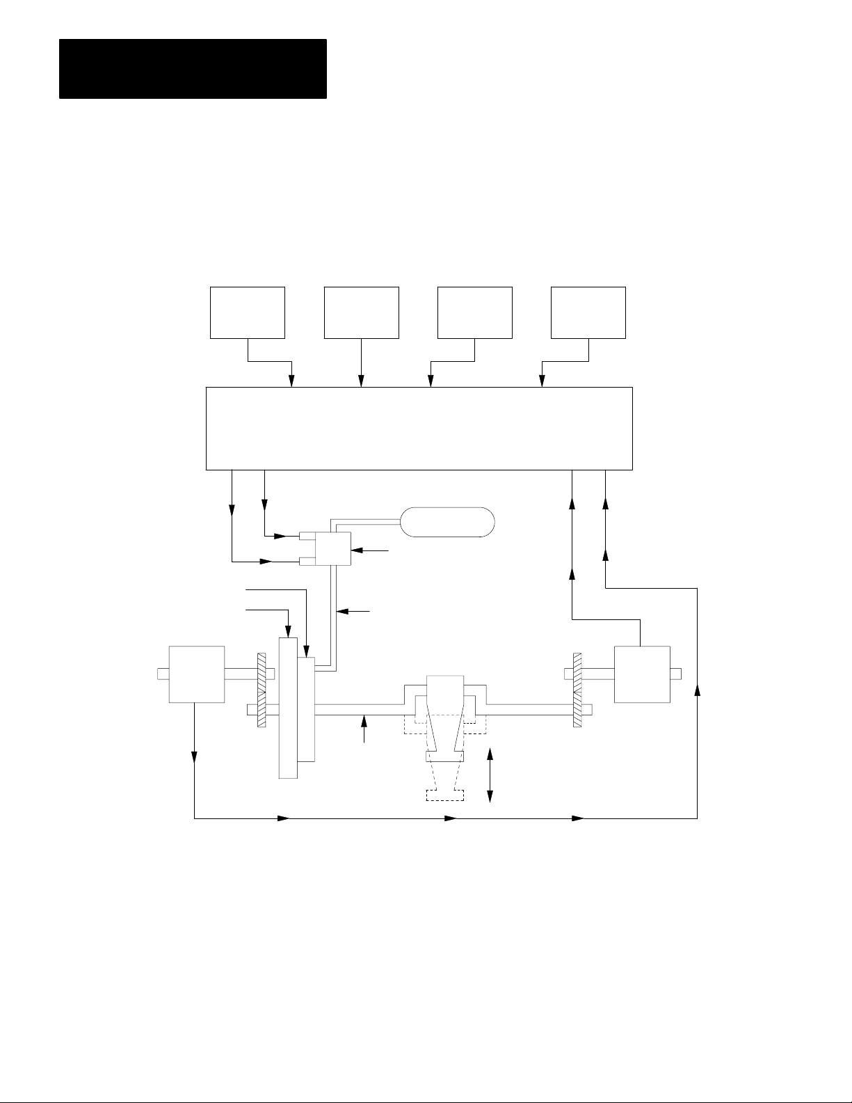
A functional block diagram of a typical press system is shown in
Figure 2.1. This figure shows general relationships between major
components. Specific functional relationships vary according to the
requirements of your particular press system. For details, refer to;
chapters 3 thru 7 of this manual
technical documentation provided by your press manufacturer
ANSI B11.1, American National Standard for Machine Tools,
Mechanical Power Presses, Construction, Care, and Use
Important: Use an Allen-Bradley clutch/brake controller only with a
mechanical power press that has a part-revolution clutch. A
part-revolution clutch can be disengaged at any position of the shaft. This
allows your clutch/brake controller to stop the press at any position. In
contrast, a full-revolution clutch can be disengaged and stop the press
only at the top position of the stroke.
21
Page 8
Chapter 2
Press System Description
Figure 2.1
Functional Block Diagram
Triac
Outputs
to Main
Solenoids
Clutch/Brake Assembly
Flywheel
Cam
Switch
Assembly
Operator
Station
No. 1
Operator
Station
No. 2
Allen - Bradley Clutch/Brake Controller
- Monitors operator inputs
- Monitors shaft position using cam limit switch feedback
- Controls the press using solenoid triac outputs
Main Solenoid Valves
Air to Clutch
Operator
Station
No. 3
Air Supply
Press
Operator
Station
No. 4
Cam Switch
Feedback
Inputs
Cam
Switch
Assembly
22
Crankshaft
Shaft at Top Position
Shaft at Bottom Position
12245
Page 9

Chapter 2
Press System Description
Related Safety Documentation
This manual concentrates on safety considerations relative to the
clutch/brake controller. Study this entire manual and all technical
documentation provided by the press manufacturer before you install your
press system. In addition to local codes and laws, follow the safety
requirements detailed in the following publications:
OSHA Regulations, Title 29-Labor, Chapter XVII, Section 1910.217,
Mechanical Power Presses
ANSI B11.1, American National Standard for Machine Tools,
Mechanical Power Presses, Construction, Care, and Use
NFPA No. 79, Electrical Standard for Metalworking Machine Tools
23
Page 10

Chapter
3
Clutch/Brake Controller Hardware
Chapter Objectives
General Hardware Considerations
This chapter will help you become familiar with the:
hardware components of your Allen-Bradley clutch/brake controller
functional relationships between your PLC and clutch/brake controller
interconnections between your PLC and clutch/brake controller
switch settings that configure your clutch/brake controller and establish
its rack addresses
For details on how to install the I/O chassis and modules, refer to the
installation publications that apply to your particular PLC. These
publications, listed in our Publications Index (publication SD-499),
discuss general layout rules, mounting dimensions, enclosure
considerations, module keying, and field wiring arm connection
technique.
Important: If you are using a large mechanical power press that
generates high levels of shock and vibration, we recommend that you
shock-mount each I/O chassis of your clutch/brake controller.
Important: Electrostatic discharge can damage integrated circuits or semi
conductors in the PM Module if you touch backplane connector pins or
internal components.
Description of your Clutch/Brake Controller
CAUTION: Rid yourself of charge before handling the module
by touching a grounded object.
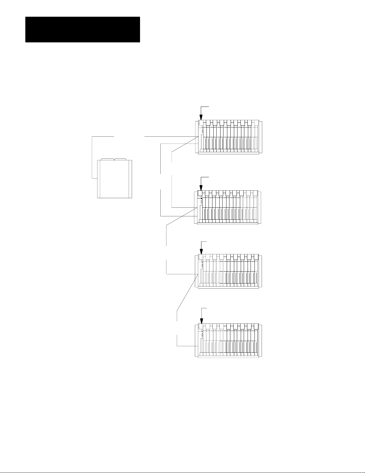
Your clutch/brake controller consists of chassis A and B connected to
your PLC in a serial chain with remote I/O chassis, as shown in
Figure 3.1. Table 3.A. lists required and optional clutch/brake controller
hardware.
Chassis A and B are similar to remote I/O chassis. The major difference
is that the left-most slot of chassis A and B contains a clutch/brake
module. In contrast, the left-most slot of an I/O chassis contains an I/O
adapter module.
31
Page 11
Chapter 3
Clutch/Brake Controller Hardware
Figure 3.1
Overview
Remote I/O
Communications
A-B Programmable Controller
with Remote I/O
of a Clutch/Brake Controller
Remote
I/O
Clutch/Brake
Remote
I/O
Voting Processor A
Clutch/Brake Module
Chassis A
Voting Processor B
Clutch/Brake Module
Chassis B
Remote I/O
Adapter Module
Remote
I/O
Chassis C
Remote I/O
Adapter Module
Remote I/O Chassis
other I/O chassis
independent of the
Clutch/Brake Controller
12246
32
Page 12

Table 3.A
Required and Optional Hardware
Chapter 3
Clutch/Brake Controller Hardware
Quantity Item
Important: (Y
2
2
2
10
2
2
1
2
2
2
ou must use 8point modules with 2slot addressing)
Clutch/Brake Module
Wiring Arm
I/O Chassis
120V AC Input Modules
120V AC Isolated Output Modules
(Series C)
120V AC Output Modules
120AC Output Module
120V AC Input Modules
120V AC Isolated Output Modules
(Series C)
I/O chassis
Cat. No.
Required Hardware
1771PM
1771WB
1771A2B
1771IA
1771OD
Optional Hardware
1771OA
1771OA
1771IA
1771OD
1771A4B
Function
Monitors and controls the press
Connections to 1771PM
Contains the modules
Monitors press inputs
Controls press outputs
Display of diagnostic messages
Controls optional indicators
Dump valve circuit
Dump valve and/or microinch circuit
Substitute chassis when using the
optional dump valve circuit.
1
2
2
120V AC Output Module
120V AC Input Modules
120V AC Input Modules
1771OA
1771IA
1771IA
Microinch indicator
Microinch circuit
Additional operator stations
Clutch/brake modules operate in parallel to monitor and control your
press. Clutch/brake modules are also called “voting processors” because
they must always have a consensus. Unless both voting processors
constantly agree that they sense identical conditions in your clutch/brake
press system, either or both voting processors stop press motion or
prevent it from starting.
Your clutch/brake controller monitors and controls your press. Although
your PLC does not control your press, it does configure and enable the
clutch/brake controller. Your PLC ladder program can monitor inputs to,
and the status of, your clutch/brake controller. This allows your PLC to
control other indicators, machines, or processes related to your press
system.
33
Page 13

Chapter 3
Clutch/Brake Controller Hardware
In addition to chassis A and B, you must connect your PLC to at least one
local or remote I/O chassis, chassis C. You need two, three, or four inputs
at a local or remote I/O chassis.
Important: You must use 2-slot addressing and 8-point (single-density)
I/O modules.
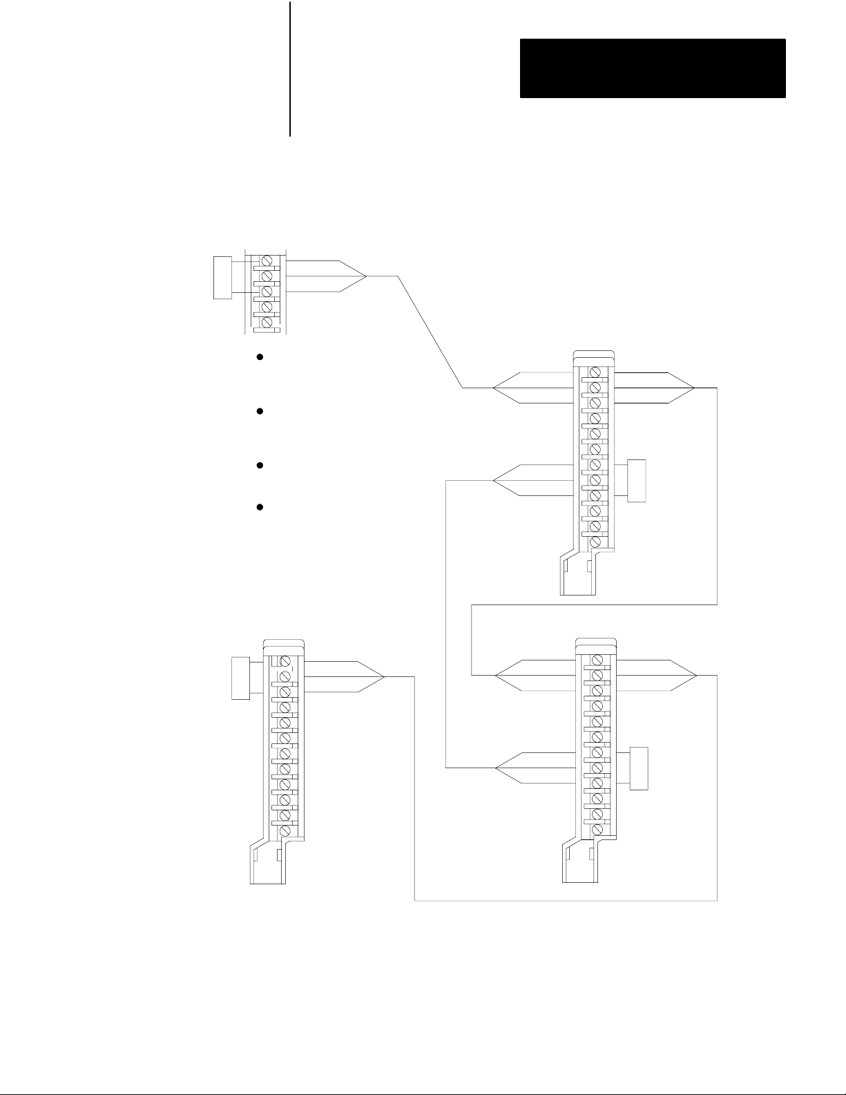
Twinaxial Cable Connections
Typical twinaxial cable connections of your clutch/brake controller are
shown in Figure 3.2. Connect your clutch/brake controller to your PLC as
part of its remote I/O distribution network. Use Twinaxial Cable (cat.no.
1770-CD) and Terminators (cat. no. 1770-XT).
Connect chassis A next to chassis B in the serial chain as shown in
Figure 3.2. You may connect one or more remote I/O chassis in the same
serial chain. Also, you may connect remote I/O chassis to other
distribution channels at the I/O scanner module of your PLC.
Connect four Terminator Resistors (cat. No. 1770-XT) as shown in
Figure 3.2. Connect one at:
the scanner module
the last chassis, whether it is a clutch/brake chassis or a remote I/O
chassis
each end of the cable that connects chassis A and B at terminals 7, 8
and 9 of the 1771-PM module field wiring arms
For more information on how to connect remote I/O channels, refer to the
installation publications that apply to your particular PLC. Also refer to
Product Data of the Remote I/O Adapter Module. These publications are
listed in our Publications Index (publication SD499)
34
Page 14
Terminator
(cat. no.
1770 -XT)
Figure 3.2
Typical
Processor/Scanner
Shield
Clear
T
winaxial Cable Connections
Blue
Chapter 3
Clutch/Brake Controller Hardware
Use Twinaxial Cable
(cat. no. 1770 -CD)
for all cable connections.
Chassis A
Terminator
(cat. no.
1770-XT)
Terminal Strip on 1772 - SD,
SD2 Remote I/O Scanner/
Distribution Module (PLC - 2)
or
Terminal Block on
1775 - S4A, - S4B, -S5,
I/O Scanner Module (PLC -2)
or
Connector on PLC - 5
Processor
or
Connector on 5/50 - RS2
Remote I/O Scanner (PLC -5/250)
Chassis C
Blue
Shield
Clear
Remote
I/O Chassis
1771 -ASB
Adapter
Module
Blue
Shield
Clear
Blue
Shield
Clear
1771 - PM
Module
Shield
Clear
Shield
Clear
Blue
Blue
Blue
Shield
Clear
Terminator
(cat. no.
1770 -XT)
1771 - WB
Wiring Arm
Chassis B
Blue
Shield
Clear
Terminator
(cat. no.
1770 -XT)
1771 - WB
Wiring Arm
1771 - PM
Module
12248
35
Page 15

Chapter 3
Clutch/Brake Controller Hardware
Multiple Clutch/Brake Controllers
Panel Switches and Operator Stations
Although this manual describes a single clutch/brake controller, you may
connect your PLC to multiple controllers, each controlling a separate
press. Each clutch/brake controller uses two remote I/O racks for chassis
A and B. For example, since a PLC-3 controller can support as many as
32 I/O racks, you may connect it to as many as 15 clutch/brake controllers
with two additional I/O racks for modules in chassis C.
You can operate your press using up to four operator stations and an
optional control panel. Installations vary according to the type of
mechanical press and its application requirements. The number of
stations, control switches contained in each, and the control panel could
be as follows:
Assembly Control
Control Panel and/or Station 1
Mode select
Arm continuous
Stopontop
L/R Inch
Press enable
Reset latched messages
Lamp test
L/R Run
EStop
Switches
Notes
1
1
1 and/or 3
2
3
3
3
2
2
Stations 2 thru 4
1 Connect these switches to input modules in chassis A and B (Figure 6.10).
2 Connect these switches to input modules in chassis A and B (Figures 6.11 thru
6.12).
3 These switches are inputs for command rungs (Figures 4.6 thru 4.8). Connect
these
switches to input modules in remote I/O chassis C (Figure 6.15).
L/R Run
Stop On T
EStop
op
2
2 and/or 3
2
36
Page 16

Chapter 3
Clutch/Brake Controller Hardware
Interlock Switches
Configuring Your Clutch/Brake Controller
Various interlock switches are required for safety as specified in ANSI
B11.1. The locations, types, and quantities vary with the type of
mechanical press and its application requirements. Use these interlock
switches to prevent the press from starting or to stop the press when
operation could cause injury to personnel or damage to the press.
Interlock
Barrier guard
Press interlock
Motion detector
Main motor forward
Cam limit switch assembly
topstopcheck (TCAM)
runon (RCAM)
antirepeat (ACAM)
Switch
Quantity Reference
1 or more
1
1
1
2
Figures 6.10 and 6.15
Figures 6.1 and 6.5
Figure 6.2 and 6.6
Figure 6.10
Figure 6.9
You have flexibility in selecting clutch/brake controller functions. You
may select any of the following functions according to your application
requirements by setting switches on the I/O chassis.
Operator station 3 and 4
Motion detector feedback
Valve stem feedback
Air pressure feedback
Ungrounded or grounded AC power
On-the-hop
Half stroke, or Stroke-and-a-half
Dump valve circuit
Micro-inch
37
Page 17
Chapter 3
Clutch/Brake Controller Hardware
Always OFF
1234
O
N
O
F
F
Switch
No:
IMPORTANT:
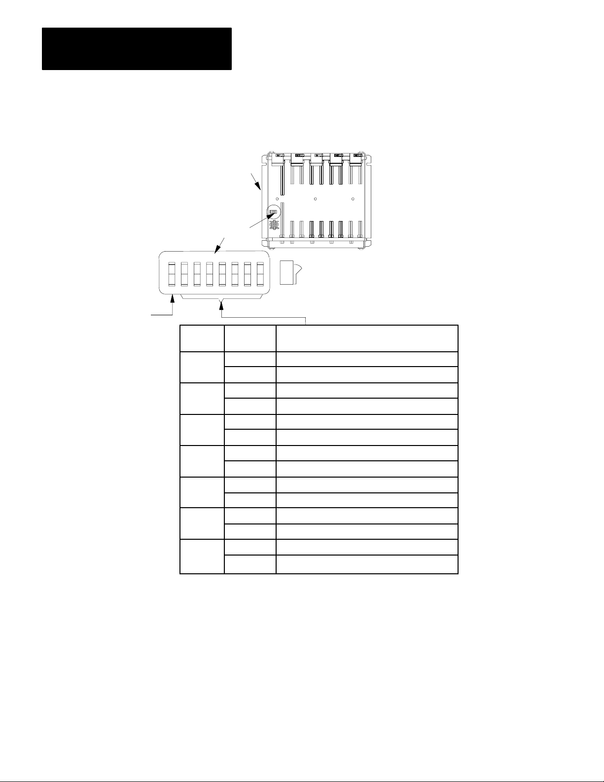
Figure 3.3
Backplane
Backplane
Assembly
2
3
4
5
6
7
8
Switch Settings
Chassis
A and B
Switches
5678
Position:
ON
OFF
ON
OFF
ON
OFF
ON
OFF
ON
OFF
ON
OFF
ON
OFF
Make backplane switch settings in chassis A and B identical.
ON
OFF
OFF
Function:
Use Stations 3 and 4
Stations 3 and 4 not used
Use Motion Detector Feedbck
Motion Detector Feedback not used
Use Valve Stem Feedback
Valve Stem Feedback not used
Use Air Pressure Feedback
Air Pressure Feedback not used
Ungrounded AC Power
Grounded AC Power
Use On-The-Hop
On-The-Hop not used
Use HalfStoke
Use StrokeAndAHalf
12249
38
Page 18

Chapter 3
Clutch/Brake Controller Hardware
Important: There is no backplane switch setting to configure the optional
dump valve circuit. You configure the optional dump valve circuit by
inserting dump valve modules (cat. no. 1771-OD and 1771-IA) into
module group 4, slots 0 and 1, respectively of chassis A and B. You must
also set bit 14 unconditionally in your configuration rungs.
Important: To configure your clutch/brake controller for Micro-inch, see
chapter 4 “Module Group 5, Slot 0 Reserved for Micro-inch”.
Important: Your PLC ladder program must include unconditioned
configuration rungs that set or reset configuration bits to match the
settings of backplane switches. Refer to chapter 4.
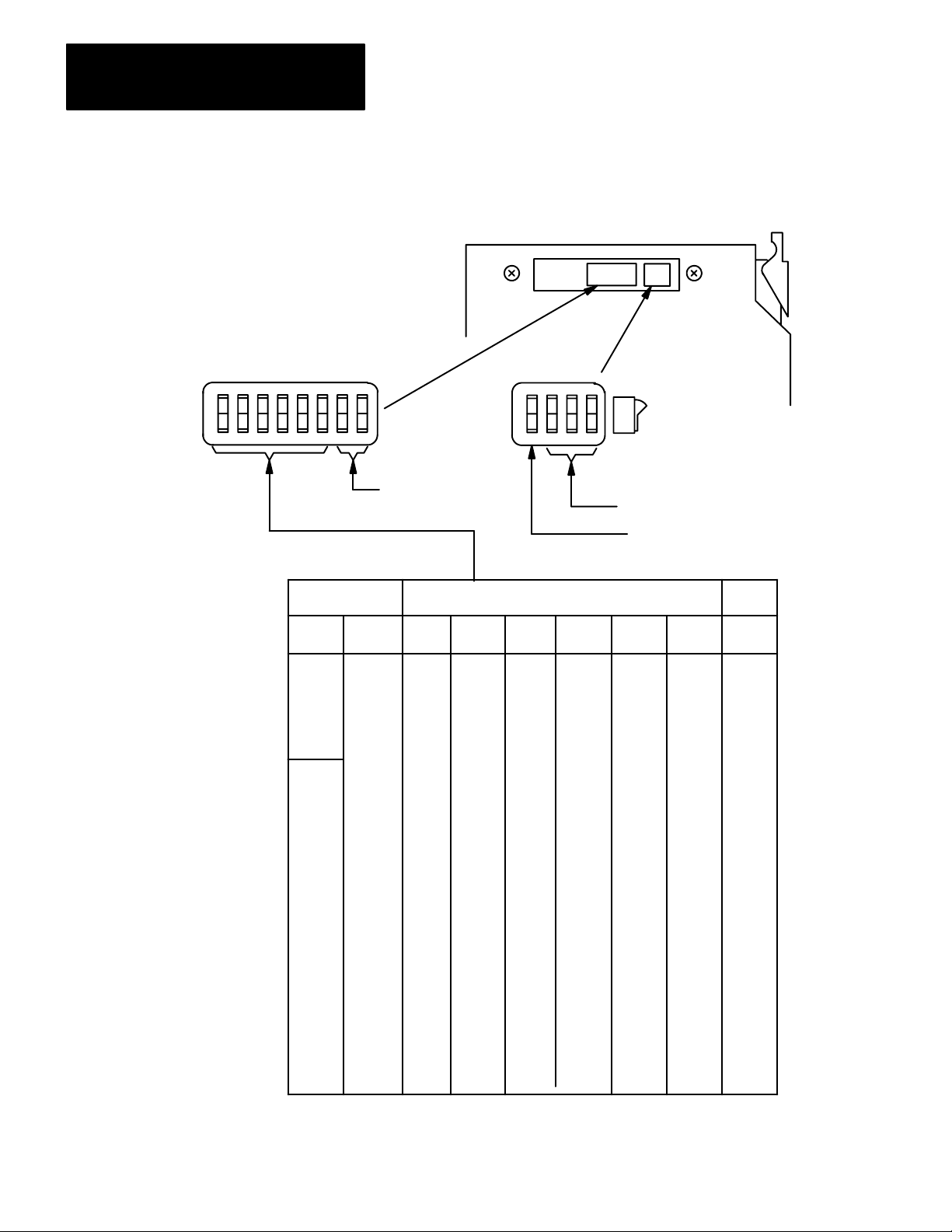
Rack Address of Chassis A and B
Establish the address of chassis A and B in each clutch/brake module so
the PLC can communicate with it. Use valid rack addresses as
determined by your PLC.
Switch assembly SW-1 determines the rack address. It is located under a
sliding cover plate on the left side of the clutch/brake module near the top.
Loosen the two screws holding the cover plate and slide it open. Locate
switch assembly SW-1 at the top of the printed circuit board as shown in
Figure 3.4.
Using switch assembly SW-1, designate chassis A and B as follows:
Chassis A - any rack address having position 6 OFF
Chassis B - next consecutive upper or lower rack address
Important: If your ladder program monitors rack adapter fault bits for
each chassis containing a clutch/brake module, the fault bits will indicate
a faulted rack whenever the module trips power to I/O swingarms. This is
because clutch/brake modules stop all communciation with the PLC until
they verify that swingarm power has been disconnected.
Important: Always configure I/O racks assigned to clutch/brake
controllers as full
racks, so the PLC can write configuration bits to each
PM chassis in Module Group 7.
39
Page 19
Chapter 3
Clutch/Brake Controller Hardware
Figure 3.4
Address Switch Setting on 1771PM Module
Rack
1234
O
N
O
F
F
SW-1
5678
Rack Addresses
PLC-2/30
PLC-5/25
1
2
3
4
5
6
7
SW-2
1234
O
Always ON (star
Module Group 0)
ting
N
O
F
F
ON
OFF
OFF
Always OFF
Always ON(57.6K baud)
Switch Assembly SW-1 Position
PLC-3
PLC-5/250
00
01
02
03
04
05
06
07
10
11
12
13
14
15
16
17
20
21
22
23
24
25
26
27
30
31
32
33
34
35
36
37
NOTE: Chassis A and B must have consecutive rack address
on
on
on
on
on
on
on
on
on
on
on
on
on
on
on
on
on
on
on
on
on
on
on
on
on
on
on
on
on
on
on
on
1
on
on
on
on
on
on
on
on
on
on
on
on
on
on
on
on
off
off
off
off
off
off
off
off
off
off
off
off
off
off
off
off
2
on
on
on
on
on
on
on
on
off
off
off
off
off
off
off
off
on
on
on
on
on
on
on
on
off
off
off
off
off
off
off
off
3
4
on
on
on
on
off
off
off
off
on
on
on
on
off
off
off
off
on
on
on
on
off
off
off
off
on
on
on
on
off
off
off
off
5
on
on
off
off
on
on
off
off
on
on
off
off
on
on
off
off
on
on
off
off
on
on
off
off
on
on
off
off
on
on
off
off
es.
on
off
on
off
on
off
on
off
on
off
on
off
on
off
on
off
on
off
on
off
on
off
on
off
on
off
on
off
on
off
on
off
Chassis
6
B
A
B
A
B
A
B
A
B
A
B
A
B
A
B
A
B
A
B
A
B
A
B
A
B
A
B
A
B
A
B
A
12250
310
Page 20

Chapter 3
Clutch/Brake Controller Hardware
For example, if you choose rack address 2 for chassis A, you must choose
rack address 1 or 3 for chassis B.
Set the rack address in each clutch/brake module. Place a label on each
clutch/brake module to identify in which chassis, A or B, it belongs.
Important: Chassis A and B rack addresses must be unique. No I/O
chassis can have the same rack address as either chassis A or B. This
restriction prohibits using the rack address of either chassis A or B for any
complementary I/O chassis (a chassis with the same module addresses but
having input modules where chassis A and B have output modules, and
output modules where chassis A and B have input modules). This
restriction also prohibits using the rack address of either chassis A or B
for any partial remote I/O chassis (a chassis that starts with module group
2, 4, or 6). (Refer to chapter 4, Module Group 7, PLC Command Rungs,
for reasons why you must restrict the use of this address.)
Setting the Communication Rate
Response Time
Triacs of your clutch/brake controller turn on in sequential order. Triacs
connected to the high AC power line (L1) turn on before those in the
triac-solenoid string connected to the low AC power line (L2). If the
addresses are reversed, the triacs will turn on out of sequence, and the
clutch/brake controller will not operate.
Set switch 1 on switch assembly SW-2 to the ON position. This sets the
module’s communication rate at 57.6K baud. Be sure that you set the
communication rate of both 1771-PM modules and the processor’s
scanner to 57.6K baud, as well.
The worst case time required for the clutch/brake controller to respond to
a change of input depends on Module-response and triac-switching times:
Delay
Characteristic
1771IA
module
response time
1771PM module
response time
T
riac switching time
T
otal response time
(ms)
26
10
8
44
311
Page 21

Chapter 3
Clutch/Brake Controller Hardware
The number of degrees that the shaft continues to rotate, beyond the
moment in time when the input changes, depends on the speed of rotation.
The greater the number of strokes per minute (SPM), the further the shaft
rotates before a command from the clutch/brake controller is applied. The
response time of 44ms is represented in degrees of shaft rotation that
increases as the rate of press operation increases (Figure 3.5).
Figure 3.5
Response
Time of Clutch Brake Controller
SPM
100
90
80
70
60
50
40
30
20
10
0
0 5 10 15 20 25
DegreesofShaftRotation
12251
Important: When estimating the braking distance in degrees of rotation,
add the response time of the controller (Figure 3.5) to the specified
downstroke or upstroke braking distance of your press.
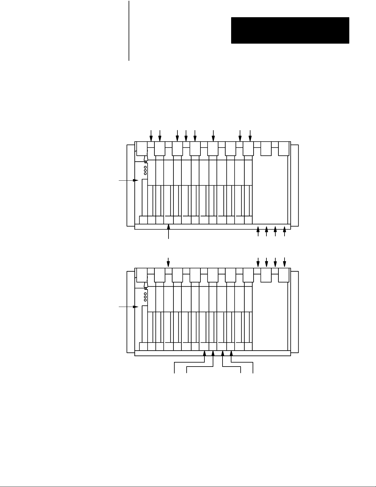
Module Placement
312
Locations of all clutch/brake controller modules are shown in Figure 3.6.
Note that some of these modules are optional.
CAUTION: Do not place any I/O module in module groups
6 or 7 of chassis A or B. These module group locations are
non-functional and reserved for future use. If you use a slot
power supply, install it in module group 7.
Important: Use series C or later 1771-OD modules because they have
improved electrical noise immunity. Refer to Electrical Noise
Suppression, in chapter 6, for a method of suppressing surge transient
noise.
Page 22
1771 -PM
module
Figure 3.6
Locations
Module
Required 1771 -IA modules for
press inputs chassis A & B
module group 0, slots 0 & 1
module group 1, slot 1
module group 2, slots 0 & 1
01234567
Chapter 3
Clutch/Brake Controller Hardware
Optional 1771 -OA modules for display of
message codes, brake fault, run window and micro inch.
module group 3, slot 1 chassis A
module group 5, slot 1, chassis A & B
Optional 1771 -IA modules for micro-inch inputs, chassis A & B
mdoule group 5, slot 0
Chassis A
1771 -A4, -A4B
Optional 1771 -IA modules for station 3 & 4
inputs chassis A & B (remove them if you do
not configure for stations 3 & 4
module group 1, slot 0
01234567
1771 -PM
module
Chassis A
1771 -A4, -A4B
Required 1771 -OD modules for outputs
to solenoid valves, Chassis A & B
module group 3, slot 0
Optional micro -inch indicator, chassis B
1771 -OA, module group 3, slot 1
Important: Use 1771A2, A2B chassis when not using optional dump valves,
display of diagnostic message codes, nor microinch inputs.
These slots must remain empty in chassis A & B
module group 6, slots 0 & 1
module group 7, slots 0 & 1
Optional modules for dump
valve in chassis A & B
1771 -OD, module group 4, slot 0
1771 -IA, module group 4, slot 1
12247
313
Page 23
Chapter 3
Clutch/Brake Controller Hardware
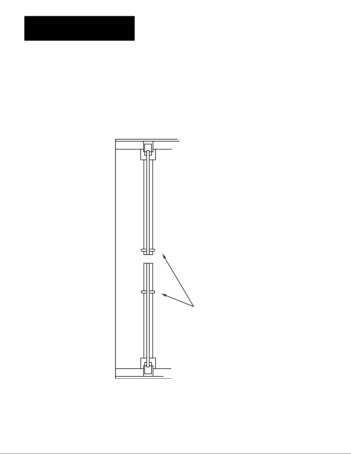
Keying
Install the keying bands on the I/O chassis backplane connector as shown
in Figure 3.7. After you install keying bands in chassis A and B, you can
insert only a clutch/brake module in the left-most slot of chassis A and B.
Figure 3.7
Keying
Chassis A and B
2
4
6
8
10
12
14
16
18
20
22
24
26
28
30
32
34
36
38
40
42
44
46
48
50
52
54
56
2
4
6
8
10
12
14
16
18
20
22
24
26
28
30
32
34
36
38
40
42
44
46
48
50
52
54
56
Insert keying bands so that you
can install only a 1771-PM
module in this slot.
12252
314
Page 24

Chapter
PLC Ladder Programming
4
Chapter Objectives
Programming Fundamentals
This chapter will help you become familiar with:
programming fundamentals as they relate to your clutch/brake
controller
the need for press configuration rungs
relationships between your press configuration rungs and backplane
switch settings
relationships between configuration rungs and voting processor
firmware
the option of monitoring the press through your PLC ladder program
the option of using PLC report generation to display messages that you
have stored.
Your PLC ladder program is composed of instructions that you enter into
PLC memory. These instructions are organized into rungs. They
typically monitor inputs and control outputs.
Your PLC ladder program does not control your clutch/brake controller,
but it does configure and enable it. Although your ladder program cannot
control any clutch/brake controller outputs, it controls output image table
bits to configure and enable the voting processors. Your ladder program
may examine input image table bits to monitor clutch/brake controller
functions as we will explain later.
This chapter concentrates on PLC ladder programming that relates to your
clutch/brake controller. For more details on ladder programming, refer to
the programming manual that applies to your PLC processor. These
publications are listed in our Systems Division Publication Index
(publication SD499).
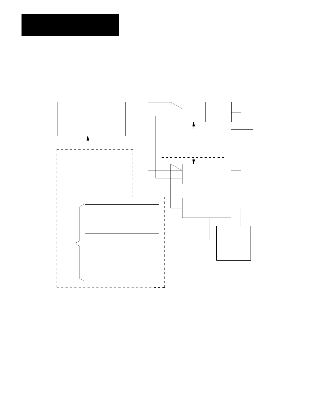
PLC ladder programming is described in this chapter as it relates to
clutch/brake controller hardware and voting processor firmware
(Figure 4.1).
41
Page 25
Chapter 4
PC Ladder Programming
Figure 4.1
Overview
A-B Programmable Controller
with Remote I/O
Your ladder diagram
program configures and
enables voting processors
A and B, while it monitors
and controls I/O through
remote I/O adapters.
I/O Control Rungs
of Clutch/Brake Controller
Thefirmwareinvoting
processors A and B
monitors and controls the press.
1771 - PM
Voting
Processor
1771 - PM
Voting
Processor
1771 - ASB
Remote I/O
Adapter
Chassis
A
Chassis
B
Chassis
C
(optional)
C/B
Press
PLC
Ladder
Program
Configuration Rungs
I/O Control Rungs
Configuration
Switch
Inputs
Other inputs
that are
independent
of the
Clutch/brake
controller
12253
42
Page 26

Chapter 4
PC Ladder Programming
Configuration Rungs
You have flexibility in selecting clutch/brake controller functions by
setting/resetting configuration bits. Use any of the following functions
according to your application requirements:
Functions Bit
3 and 4
Stations
Motion detector feedback
alve stem feedback
V
Air pressure feedback
Ungrounded or grounded AC power
Onthehop 06
Halfstroke or Strokeandahalf
Dump valve circuit
01
02
03
04
05
07
14
You enable various functions by programming configuration rungs to set
(turn on) or reset (turn off) configuration bits 01 thru 07 and 14 in the
output image table word for module group 7, chassis A and chassis B.
Bit addresses are shown in Figure 4.2. Example configuration rungs are
shown in Figure 4.3 through Figure 4.5. Program your configuration
rungs according to the requirements of your press system.
Be sure to set or reset each configuration bit 01 thru 07 and 14 with
unconditioned rungs. They contain only output instructions, such as latch,
unlatch, or output energize. Bits set by these rungs do not change during
press operation. The latching or unlatching of these bits must correspond
with backplane switch settings covered in chapter 3.
Figure 4.2
addresses of Output Image T
Bit
PLC-2/20 PLC-3
PLC-2/30 PLC-5/250
0y7/xx Oyy7/xx O:y7/xx
where yy = rack address per Figure 3.4
xx = bit number 00 - 17
Important: Do not use bits 00 and 15-17 for any purpose.
able W
ord for Module Group 7 of Chassis A & B
PLC-5
43
Page 27

Chapter 4
PC Ladder Programming
Figure 4.3
Example
Stations 3 and 4 not used
Motion detector feedback used
Valve stem switch feedback used
Air pressure switch feedback not used
PLC Configuration Rungs for Bits 01 thru 07 and 14 (PLC2 Family)
057
U
01
067
U
01
057
L
02
067
L
02
057
L
03
067
L
03
057
U
04
067
U
04
Ungrounded AC power
On-the-hop not used
Strokeandahalf used
Optional dump valve triacs used
057
L
05
067
L
05
057
U
06
067
U
06
057
U
07
067
U
07
057
L
14
067
L
14
44
Page 28

Chapter 4
PC Ladder Programming
Figure 4.4
Example PLC Configuration Rungs for Bits 01 thru 07 and 14
(PLC3 and PLC5/250)
Stations 3 and 4 not used
Motion detector feedback used
Valve stem switch feedback used
Air pressure switch feedback not used
Ungrounded AC power
O0057
U
01
O0057
L
02
O0057
L
03
O0057
U
04
O0057
L
05
O0067
(
U
01
O0067
)
(
L
02
)
)
)
O0067
(
L
O0067
(
U
O0067
(
L
03
04
05
On-the-hop not used
Half-stroke or Stroke-and-a-half used
Optional dump valve triacs used
NOTE: Unconditionally latch or unlatch bits 0 through 7 and 14 for chassis A and B as shown to use these functions.
Use this address format for PLC-5/250 processors
O:057
U
01
)
O:067
(
U
01
O0057
U
06
O0057
U
07
O0057
L
14
)
)
)
O0067
(
U
O0067
(
U
O0067
(
L
06
07
14
45
Page 29

Chapter 4
PC Ladder Programming
Figure 4.5
Example PLC Configuration Rungs for Bits 01thru 07 and 14
(PLC5 family)
Stations 3 and 4 not used
Motion detector feedback used
Valve stem switch feedback used
Air pressure switch feedback not used
Ungrounded AC power
On-the-hop not used
Stroke-and-a-half or Half-stroke used
Optional dump valve triacs used
NOTE: Unconditionally latch or unlatch bits 0 through 7 and 14 for chassis A and B as shown to use these functions.
(
O:57
(
(
(
(
(
(
(
O:67
O:57
U
01
O:67
U
01
L
02
O:67
L
02
O:57
L
03
O:67
L
03
O:57
U
04
O:67
U
04
O:57
L
05
O:67
L
05
O:57
U
06
O:67
U
06
O:57
U
07
O:67
U
07
O:57
L
14
L
14
)
)
)
46
Page 30

Chapter 4
PC Ladder Programming
Matching Configuration Bits and Backplane Switches
As listed in Table 4.A, backplane switch positions 2 thru 8 correspond
with configuration bits 01 thru 07. The voting processors in your
clutch/brake modules allow press operation only if the set (on) and reset
(off) states of configuration bits in your program correctly match the ON
and OFF settings of corresponding backplane switches. The voting
processors check for correct configuration when you apply power to your
clutch/brake controller or change its mode of operation using the mode
select switch.
Table 4.A
Corresponding
Backplane
Switch
Settings
(figure 3.3)
Pos. Setting Bit: Status: Function:
2 ON 01 Set
Backplane Switch Settings and Configuration Bits
Configuration
Bits
OFF reset
Backplane switch settings and configuration bits
must be identical
Use Stations 3 and 4
Stations 3 and 4 not used
3 ON 02 set
OFF reset
4 ON 03 set
OFF reset V
5 ON 04 set
OFF reset
6 ON 05 set
OFF reset
7 ON 06 set
OFF reset
8 ON 07 set
OFF reset
Module Group 4
Slot 1, Chassis A&B
1771IA
Module Group 4
Slot 1, Chassis A&B
is EMPTY
14
Set
reset
Use Motion Detector Feedback
Motion Detector Feedback not used
Use V
alve Stem Feedback
alve Stem Feedback not used
Use Air Pressure Feedback
Air Pressure Feedback not used
Ungrounded AC Power
Grounded AC Power
Use OnTheHop
OnTheHop not used
Use Halfstroke
Use StrokeAndAHalf
Use Dump V
alve Outputs
Dump V
alve Outputs not used
47
Page 31

Chapter 4
PC Ladder Programming
PLC Command Rungs
Your ladder diagram program can send four commands to the clutch/brake
controller by setting command bits 10-13 in the output image word for
module group (MG) 7, Slot 1 for I/O chassis A and B:
Command Bit
enable
Press
Stopontop
Reset latched messages
Lamp test
10
11
12
13
These commands can be issued manually by an operator pushing a switch,
or automatically by a switch closure in your machinery. They function as
follows:
Output Status Condition
Press Enable
Bit 10
Stopontop
(Continuous mode, only)
Bit 1
1
must be ON
OFF
offtoon
transition
must be OFF
T
o enable motion in any mode
Immediately turns OFF triac outputs
T
urns OFF solenoid outputs the next time the
runon cam switches open
T
o start or maintain continuous stroking
Controlled by PM Module
Reset Latched Message
Bit 12
Lamp T
est
Bit 13
1
Holding this bit ON may inhibit the capture of subsequent L or t messages.
offtoon
transition
ON
OFF
Clears any latched or tripped message code
1
shown in MG 5, Slot 1, as long as the condition
that caused the message no longer exists.
T
urns ON all these outputs
Brake Fault , Run Window
and other diagnostic message lamps
T
urns OFF these outputs
Bit addresses for these command bits are shown in Figure 4.2. Example
PLC command rungs are shown in Figure 4.6 through Figure 4.8.
To enable these commands, write ladder program rungs that are
conditioned with examine-on/examine-off instructions to monitor
corresponding switch inputs wired to I/O chassis C. You can use any
available discrete module terminals (excluding those in chassis A or B)
for these inputs (Figure 6.15). For additional information refer to chapter
6, Inputs to Chassis C .
, Microinch Message,
48
Page 32

Chapter 4
PC Ladder Programming
132
13
132
13
132
15
132
15
132
132
PRESS ENABLE Switch
STOP-ON-TOP Switch
RESET Switch
14
Figure 4.6
Example
Optional conditions
Enable Press Operation
Command Stop-on-top
Reset latched messages
PLC Command Rungs for Bits 10 thru 13 (PLC2 Family)
057
10
067
10
057
11
067
11
057
12
067
14
132
16
132
16
NOTE:
12
LAMP TEST Switch
Test optional indicators
PLC command bits 10 through 13 use conditioned logic. Do not latch or unlatch instructions. Corresponding
switch input wiring is shown in Figure 6.15.
057
13
067
13
49
Page 33

Chapter 4
PC Ladder Programming
PRESS ENABLE Switch
Figure 4.7
Example PLC Command Rungs for Bits 10 thru 13
(PLC3 and PLC5/250)
Optional conditions
I0032
13
I0032
15
I0032
14
I0032
Enable Press Operation
STOP-ON-TOP Switch
Command Stop-on-top
RESET Switch
Reset latched messages
LAMP TEST Switch
O0057
10
O0057
11
O0057
O0057
12
O0067
10
O0067
11
O0067
12
O0067
410
16
NOTE:
13
Test optional indicators
PLC command bits 10 through 13 use conditioned logic. Do not latch or unlatch instructions. Corresponding
switch input wiring is shown in Figure 6.15.
Use this address format for PLC-5/250 processors
O:057
U
01
)
O:067
(
U
01
13
Page 34

PRESS ENABLE Switch
Optional conditions
Chapter 4
PC Ladder Programming
Figure 4.8
Example PLC Command Rungs for Bits 10 thru 13 (PLC5)
I032
13
I032
15
I032
14
I032
Enable Press Operation
STOP-ON-TOP Switch
Command Stop-on-top
RESET Switch
Reset latched messages
LAMP TEST Switch
O:57
10
O:67
10
O:57
11
O:67
11
O:57
12
O:67
12
O:57
16
NOTE:
13
Test optional indicators
PLC command bits 10 through 13 use conditioned logic. Do not latch or unlatch instructions. Corresponding
switch input wiring is shown in Figure 6.15.
O:67
13
411
Page 35

Chapter 4
PC Ladder Programming
Summary of PLC Configuration and Command Rungs
Output image table word,
Module Group 7, Chassis
A & B
Bit Bit
No: Function: Set Reset Rung:
01
02
03 V
Stations 3 and 4
Motion Detector Feedback
alve Stem Feedback
We summarize the bits in module group 7 used for determining
configuration requirements and enabling operator commands (Figure 4.9).
Figure 4.9
Functions
17161514131211100706050403020100
of PLC Configuration and Command Bits
PLC Configuration Bits
PLC Command Bits
Status
Used
Used
Used
Not Used
Not Used
Not Used
T
Unconditioned
Unconditioned
Unconditioned
ype of
04
05
06 OnTheHop Used
07
10
11 StopOnT
12
13
14
NOTES: Do not use bits 00 and 15 17 for any purpose.
See Figure 4.2
See Figure 4.3
Air Pressure Feedback
AC Power Configuration
Strokeandahalf or Halfstroke
Press Enable (PLC Command)
op (PLC Command)
Latched Messages (PLC Command)
Lamp T
est (PLC Command)
Dump V
alve T
riacs Used
for bit addresses
through 4.8 for programming
Ungrounded Grounded Unconditioned
Used
Not Used
Enabled Disabled Conditioned
Enabled Disabled Conditioned
Enabled Disabled Conditioned
Enabled Disabled Conditioned
Not Used
Not Used
Used Unconditioned
Not used
Unconditioned
Unconditioned
Unconditioned
12254
412
Page 36

Chapter 4
PC Ladder Programming
Module Group 5, Slot 0
Reserved for MicroInch
Module Groups 6 and 7 Reserved for Data Storage
Important: Use module group 5, slot 0 only if your mechanical power
press is equipped for micro-inch.
When you insert an input module (1771-IA) into this slot of chassis A and
B, the processor recognizes micro-inch inputs at terminals 0, 1, 2. For the
wiring of these terminals refer to chapter 6, Figure 6.4 or
Figure 6.8.
Module group 6 is non-functional and reserved for future use.
Your program must use the output image table word associated with
module group 7 as a storage word for configuring your clutch/brake
modules (Figure 4.9). The processor transmits configuration data to the
clutch/brake modules in each I/O scan.
CAUTION: Do not assign any I/O module to module group 7
of the rack address assigned to chassis A and B. Unexpected
press operation will occur with possible damage to equipment
and/or injury to personnel. However, you may install a slot
power supply in module group 7, if needed.
Monitoring Clutch/Brake Controller Inputs and Outputs
Important: Be sure to assign full rack addresses for chassis A and B,
regardless of whether you are using the optional dump valve and/or
micro-inch circuit. This guards against assigning an I/O module to
module group 7.
Refer to Rack Address of Chassis A and B, in chapter 3, for instructions
on assigning rack addresses.
Your PLC ladder program cannot control outputs of your clutch/brake
controller. However, your PLC ladder program can monitor any
clutch/brake controller input or output because the I/O image table of
chassis A and B is in the PLC data table.
Input image table bit addresses for chassis A and B are listed in tables A
thru F in appendix 1. You may monitor these addresses. However, do not
examine them as conditions for configuration rungs shown in Figures 4.3
through Figure 4.5. If you do, PM modules may stop the press. Then
you must cycle power to restart.
413
Page 37

Chapter 4
PC Ladder Programming
For an example of monitoring a clutch/brake controller function, assume
that you wish to turn on a indicator while your clutch/brake controller is
in continuous mode. You would wire your CONTINUOUS indicator to a
terminal of an output module in any I/O chassis. You would also program
a rung with one examine-on instruction and one output-energize
instruction:
the examine-on instruction monitors input image bit 03 for module
group 0 chassis A or B.
the output energize instruction controls the CONTINUOUS indicator.
Important: Do not store data in unused data table addresses for chassis A
and B. These are reserved for future enhancements for the clutch/brake
controller.
Report Generation
Your PLC ladder program can monitor clutch/brake controller functions
for report generation. This allows you to display, through an RS-232-C
peripheral device, any of the following:
operator instructions fault correction procedures
status reports diagnostic message codes
The clutch/brake module generates diagnostic message codes presented in
table 7.C. Use them to generate messages that you have stored in PLC
memory. These messages can be troubleshooting instructions to your
press operators. For detailed descriptions of report generation, see the
following publications:
For PLC-2 family processors:
PLC-2 Family Report Generation Module (cat. no. 1770-RG) User’s
Manual (publication 170-815)
For PLC-3 processors:
I/O Scanner-Message Handling Module (cat. no. 1775-S4B) User’s
Manual (publication 1775-6.5.3)
Peripheral Communications Module (cat. no. 1775-GA) User’s Manual
(publication 1775-6.5.4)
414
For PLC-5 family processors:
BASIC Module (cat. no. 1771-DB) User’s Manual (publication
1771-6.5.34)
Page 38

Chapter 4
PC Ladder Programming
Summary of Clutch/Brake Controller Functions
Function or Command
You should now be familiar with required and optional PLC ladder
programming needed to configure and monitor your clutch/brake
controller. Complete your ladder diagram programming addresses after
you have wired your press system as described in chapter 6. Clutch/brake
controller functions (Table 4.B) are summarized on the next page.
Table 4.B
Summary
Off
Inch
Microinch
Singlestroke
of Clutch/Brake Controller Functions
Operating Mode
[ 1 ]
Description
Clutch/brake controller locks out press motion
The operator can jog the press through a complete cycle by
pressing and releasing the pair of INCH buttons. If INCH
buttons are held, the press will stop at the top of its stroke.
This mode of operation lets you run your press at low speeds
(1 to 5spm) for setting up dies and making trial runs. Y
supply a separate drive and clutch/brake assembly to drive the
shaft with full tonnage capacity at low press speeds, bypassing
the flywheel.
The press completes one cycle and then stops on top, provided
the operator holds both RUN buttons until completion of the
down stroke.
ou must
Continuous
[ 1 ]
Stopontop
(cycle stop)
Onthehop Singlestroke
Halfstroke or
Strokeandahalf
[ 1 ] Cam limit switches must indicate that the press is in the neartop position before motion can start in
single or continuous mode.
Continuous
Continuous
Operators must assert the ARM CONTINUOUS switch and all
station RUN buttons within five seconds, and then hold the RUN
buttons for half a stroke (or 1 1/2 strokes) if so configured to
start the press in continuous mode. Thereafter
until stopped by a stopontop command, or when a fault is
detected.
This command, from a switch wired to the clutch/brake
controller or from the PLC, stops the press at a predetermined
point.
Releasing and pressing both RUN buttons during a specific
portion of the upstroke causes the press to continue running
onto the next stroke without stopping. This is a configurable
option.
The operator must press both RUN buttons for 1/2 or 1 1/2
press cycles before the press can run on its own. This is a
configurable option. Run buttons must be held until Runon
(takeover) Cams are made.
, the press runs
415
Page 39

Chapter 4
PC Ladder Programming
Function
or Command
Interrupted stroke
Interrupted stroke
Antitiedown All
Antirepeat Singlestroke
Operating Mode
Continuous
Singlestroke
Inch
Description
If an operator releases a RUN button during a down stroke, the
press stops immediately
operator releases both RUN buttons and presses them again,
the press continues the downstroke. If more than five seconds
elapses, the operator must inch the press to top, select
continuous mode, and follow the first Continuous procedure
above..
Same as Continuous mode except there is no time limit on
reapplying the RUN button.
The press will not start if you tie down one or more RUN
buttons. After all RUN buttons are released, the operator must
press both RUN buttons at a station simultaneously
operators at active stations must press all RUN buttons within
five seconds of each other to start the press.
The same applies to the pair of INCH buttons.
The press is limited to a single stroke, even if the operator
continues to press both RUN buttons. The operator must
release both RUN buttons and press them again to start press
motion.
The same applies to a pair of INCH buttons as described for
Singlestroke.
. If within five seconds of stopping, an
, and/or
Motion detector
TopstopCheck All
Singlestroke
Continuous
The clutch/brake controller detects press motion using your
motion detector which provides a 120AC input signal. This is a
configurable option.
The clutch/brake controller signals a worn or faulty brake by
monitoring the T
T
opstopcheck cam closed after a normal cycle stop has been
initiated and before the press comes to a top stop, it prevents
the press from restarting and energizes the brakefault output.
opstopcheck cam inputs. Should it see the
416
Page 40

Chapter
Voting Processor Firmware
5
Chapter Objectives
Operation of Voting Processors
This chapter will help you become familiar with:
operation of your voting processor firmware
operational sequences for controlling your press
A clutch/brake controller has two clutch/brake modules, one in chassis A
and the other in chassis B. Each clutch/brake module contains firmware
that makes it function as a voting processor. Both voting processors
contain identical firmware programs that independently monitor your
clutch/brake controller I/O while controlling the press.
While running their firmware programs, both voting processors constantly
“vote” on the status of your press. Both voting processors must always
have a consensus. If they find that they don’t agree on their perceived
conditions of your press, they either stop the press or prevent it from
starting.
Also, both voting processors constantly check their communication
channels. Press motion is stopped or inhibited if either voting processor
detects a loss of communications with the PLC or the other voting
processor. A failure in one voting processor is immediately seen as a
communication loss by the other voting processor.
Emergency Shut Down
Finally, voting processors control the operational sequences that your
operators must perform in inch, single, and continuous modes.
Each voting processor (PM module) controls one seal relay and one
crowbar relay. All E-STOP switches are connected in series with seal
relay contacts. If any of these contacts opens or if the PM module detects
a trip condition, solenoid power is disconnected. If a PM module detects
that solenoid power should be off when on, it turns on the crowbar relay
to blow the solenoid power line fuses. At clutch/brake start, both PM
modules test their crowbar relays without blowing the line fuses. Wiring
diagrams in chapter 6 show these connections.
51
Page 41

Chapter 5
Voting Processor Firmware
Fault Monitoring
PM modules continuously monitor your clutch/brake system for a trip or
stop condition. Either condition halts and/or prevents press operation.
For
this condition
Trip
Stop T
PM modules remove solenoid power by
Removing power from field wiring arms
urning of
controlling the solenoids
f outputs from the output module
Trip condition - A PM module turns off swing arm output power by
de-energizing its seal relay output when it detects these trip conditions:
lost communications with the other PM module for 100ms
a change in wiring of operator stations 1 thru 4
a short or open solenoid triac
short or open solenoid
feedback [1] connections are wired but not configured
feedback connections are configured but not wired
feedback signals are not working correctly
[1]
feedback from valve stem switches, air pressure sensors, and motion detector contacts
Whenever a PM module detects a trip condition, it:
trips power to the wiring arms of the I/O chassis
sets rack fault bits
stops communication with the PLC
If programmed to monitor rack fault bits, the PLC sees the clutch/brake
I/O chassis as faulted until both PM modules verify that power to wiring
arms has been removed. Then they resume communications
automatically.
Stop condition - A PM module stops the press or prevents it from starting
by turning off output triacs to solenoid valves when it detects stop
conditions such as:
lost communications with the other PM module for 50ms
lost communications with the PLC for one second
cam limit switch signals out of sequence
barrier guard opened during continuous mode
This is described further in Chapter 7, Diagnostic Message Codes.
52
Page 42

Chapter 5
Voting Processor Firmware
Operation of Cam Limit Switches
The PM Module uses cam limit switches to determine press slide position.
(Figure 5.1 and Table 5.A). You set two independent cam limit switch
assemblies to the same settings so that:
run-on contacts are closed in the near bottom and upstroke zones
top-stop-check contacts are closed in the downstroke and near-bottom
zones
anti-repeat contacts open during mid-upstroke for at least 70ms. Set the
open span to the approximate number of rotational degrees (10
0 -
450)
according to the speed of the press (1spm - 100spm).
UpStroke
Press
Speed
Span vs. Press Speed for AntiRepeat Contacts
SPM
100
90
80
70
60
50
40
30
20
10
0
15
OpenSpanDuringUp-Stroke
00
30
45
12971
The anti-repeat cam is not required while operating in inch or micro-inch
mode. However, before entering any operating mode, the PM module
checks that at least one cam limit switch is closed at any point in the
cycle.
53
Page 43

Chapter 5
Voting Processor Firmware
Figure 5.1
Limit Switch Settings
Cam
Run - On
Upstroke
Anti - Repeat
Near Top
Position
70 ms
Near Bottom
Zone
Top-stopcheck
Downstroke
Table 5.A
Operation
NOTE:
Install two mechanically independent cam limit switch assemblies each with three cams and three
limit switches. Set the assemblies to similar settings according to the requirements of your press.
You can set cam limit switches to other configurations provided they meet the make/break conditions
listed below:
Cam Linit Switch Settings
Top-Stop
Zone
-Check
MAKE
Downstroke
MAKE
Near
Bottom
BREAK
Upstroke
BREAK
BREAK
BREAK
Near
Top
Refer to Diagnostic Messages, table 7.C. Hex codes 80 thru AA, for descriptions of faults caused
by cam limit switches.
Run-On
BREAK
MAKE
MAKE
MAKE
MAKE
BREAK
AntiRepeat
MAKE
MAKE
MAKE
BREAK
MAKE
MAKE
Topstopcheck
before run-on contacts make, or the controller faults.
Run-on contacts must make (not necessarily at the same time)
before
T
opstopcheck contacts must break (not necessarily at the same time)
before antirepeat contacts break or the controller faults.
Anti-repeat contacts must break for at least 70ms during
upstroke, then make before run-on contacts break, or the controller faults.
Anti-repeat contacts must make (not necessarily at the same time)
before run-on contacts break, or the controller faults.
Run-on contracts must break (not necessarily at the same time)
before T
contacts must make (not necessarily at the same time)
T
opstopcheck contacts break, or the controller faults.
opstopcheck contacts make or the controller faults.
Comments
of Cam Limit Switches
12970
54
This
Cam
Anti
Repeat
Runon
TopStop
Check
In this
Mode
Onthehop single
stroke
Inch and Microinch
(forward) and Single
stroke
Continuous
Single stroke and
Continuous
any
Inch and
Microinch
(reverse)
W
ith these
Conditions
Run buttons released
past bottom
Cam opens at neartop
position T
Cam opens at neartop
position after
stopontop command
Cam closes at
nearbottom position
Cam closes during
stopontop
Cam opens in neartop
position
Provides the PM Module a Signal:
T
o allow a second stroke when run buttons
are pressed a second time
o turn OFF triac output for
stopontop (cycle stop)
T
o let operator release any depressed run
buttons without interrupting a single stroke
or continuous stroking
T
o energize a Brake Fault output to warn
that the brake is faulty (Hazardous
Condition)
T
o turn OFF solenoid outputs to stop the
cycle
Page 44

Chapter 5
Voting Processor Firmware
Clutch/Brake Operating Modes
Select inch or microinch
No
Has an operator released
both INCH buttons?
Has an operator pressed
both INCH buttons
Inch and Microinch Modes
Use inch or micro-inch mode before entering single or continuous mode
to position the shaft near the top, or for machine tool set-up. You may jog
the shaft either forward or in reverse. The shaft stops when it moves into
the near top position or when you release an INCH button.
Figure 5.2
Operational
mode
Yes
simultaneously?
Yes
Sequence for Inch or MicroInch Mode
WARNING: To guard against the
possibility of personal injury, install a
keylock mode select switch so that only
supervisory personnel can select inch
mode.
No
Both voting processors
energize their solenoid triacs
to actuate the clutch
Has the shaft moved into its
neartop position?
deenergize their solenoid
triacs to stop the shaft in its
NOTE: Use inch or microinch mode to position the shaft near the top. Operators may
jog the shaft in either direction. The shaft stops when it moves near top position or
when an operator released an INCH button.
No
Yes
Both voting processors
neartop position
Has an operator released
either INCH button?
Yes
WARNING: If the shaft
coasted past its neartop
position while braking, the
brake is faulty and
hazardous. Repair it
immediately.
No
12261
55
Page 45

Chapter 5
Voting Processor Firmware
Single Stroke Mode
Use single-stroke mode to actuate the press through a single cycle.
During the downstroke (Figure 5.3)
releasing a RUN button stops the press
if the shaft did not enter the near bottom zone, you may resume the
downstroke
if the shaft entered the near bottom zone, you must inch the press back
to the near top position before restarting
During the upstroke (Figure 5.4)
the shaft continues automatically through the upstroke
If you enabled on-the-hop , you can start another cycle without stopping
the press if you
release all RUN buttons after the near bottom position
press all RUN buttons after the anti-repeat contacts open during the
upstroke
56
Page 46

Chapter 5
Voting Processor Firmware
Start onthehop
downstroke.
From figure 5.4
Figure 5.3
Operational
Select single mode
Main Motor Forward
Yes
Is the shaft near the top?
Yes
Have all operators released all
RUN buttons?
Yes
Has each operator pressed his
RUN buttons simultaneously,
and within 5 seconds for all
stations?
Yes
Both voting processors
energize their solenoid triacs to
actuate the clutch for the
downstroke
Sequence for Downstroke in Single Mode
No
No
No
Select inch mode and position the
shaft near the top.
No
Has an operator released a
RUN button?
Is the shaft past the near
bottom zone?
Yes
Start upstroke.
Go to figure 5.4
NOTE: Releasing a RUN button during the downstroke stops the press. If the shaft does
not reach the nearbottom zone, operators may resume the downstroke. If the shaft
reaches the nearbottom zone, an operator must inch the press back to the neartop
position.
No
Both voting processors
deenergize their solenoid
triacs to stop the shaft. A stop
condition message is
Did the shaft coast into the
near bottom zone while
No
Have all operators released all
Has each operator pressed his
Yes
RUN buttons simultaneously,
and within 5 seconds for all
Yes
displayed.
breaking?
No
RUN buttons?
Yes
stations?
Yes
CAUTION: Releasing a RUN
button late in the downstroke
can damage the press
No
12262
57
Page 47

Chapter 5
Voting Processor Firmware
Both voting processors
deenergize their solenoid triacs
to stop the shaft. A stop condition
mesage is displayed.
Yes
Has the shaft moved into its
neartop position?
No
No
Figure 5.4
Operational
Start upstroke.
From figure 5.3
Upstroke continues regardless of
releasing RUN buttons
Have both voting processors
detected that antirepeat cams
have opened?
Yes
Has onthehop been enabled?
Sequence for Upstroke in Single Mode
Yes
Have all operators released all RUN
buttons?
Yes
Yes
Has each operator pressed his RUN
buttons simultaneously, and within 5
seconds for all stations?
Yes
Has the shaft moved into its neartop
position?
No
Has the shaft moved into its neartop
position?
No
Yes
No
Has the shaft moved into its
neartop position?
No
NOTE: The shaft continues automatically through its upstroke, then stops. If onthehop has
been enabled, operators can start another downstroke without stopping at the top. Do this by
releasing all RUN buttons after the downstroke. Then, press all RUN buttons after the antirepeat
contacts open on the upstroke.
Yes
Both voting processors
deenergize their solenoid triacs
to stop the shaft in its neartop
position
WARNING: If the shaft coasted
past its neartop position while
braking, the brake is faulty and
hazardous. Repair it immediately.
No
No
Has an operator released a RUN
button?
Yes
Start onthehop downstroke.
Go to figure 5.3
12263
58
Page 48

Chapter 5
Voting Processor Firmware
Continuous Mode
Select continuous mode when you want to run your press continuously.
Do this as follows:
inch the press to the near top position
close the barrier guard(s)
select continuous mode, and
press the ARM CONTINUOUS button (Figure 5.5)
During the first downstroke (Figure 5.6).
releasing a RUN button or opening a barrier guard stops the press
if the shaft did not enter the near bottom zone, you may resume the
downstroke within five seconds after a stop
if the shaft entered the near bottom zone and is stopped, you must inch
the press to the near top position and press the ARM CONTINUOUS
button in order to restart press operation.
During the first upstroke (without stroke-and-a-half) (Figure 5.7)
releasing a RUN button does not stop the press
opening a barrier guard stops the press
if the shaft did not stop in the near top position, inch it there and repeat
the procedure from the beginning
If you configured for half-stroke or stroke-and-a-half requirement
continue holding the RUN buttons until the shaft runs through the first
(or second) downstroke and first (or second) near bottom position
releasing a RUN button stops the press, and first downstroke conditions
apply
Once in continuous operation (NO TAG), the press stops whenever
you press stop-on-top
the PLC transfers a stop-on-top command
a barrier guard opens
either voting processor detects a trip or stop condition
59
Page 49

Chapter 5
Voting Processor Firmware
Figure 5.5
Operational
Select continuous mode
Is the barrier guard closed?
Is the shaft in the neartop
Main Motor Forward
Have all operators released all
STOPONTOP buttons?
Have all operators released all
Sequence for Starting Continuous Mode
Yes
position?
Yes
Yes
Yes
RUN buttons?
No
No
No
No
No
Select inch mode and position the
shaft to the neartop position
Arming Sequence
Yes
Has an operator pressed the ARM
CONTINUOUS button?
Yes
Have 5 seconds elapsed since
pushing ARM CONTINUOUS?
No
Has each operator pressed his
RUN buttons simultaneously, and
within 5 seconds for all stations?
Yes
Go to First Downstroke
Figure 5.6
NOTE: The arming sequence guards against accidently starting operation in continuous mode.
No
Yes
No
12264
510
Page 50

Chapter 5
Voting Processor Firmware
First Downstroke.
From figure 5.5
Both voting processors
energized their solenoid triacs
for the first downstroke
Has the shaft reached the
nearbottom position?
Yes
Go to First Upstroke.
Figure 5.7
Figure 5.6
Operational
No
No
Sequence for First Downstroke in Continuous Mode
Go to Figure 5.5
Select Continuous Mode
Select inch mode and position the
shaft near the top.
Has an operator released a
RUN button, or has a barrier
guard opened?
Yes
Both voting processors
deenergize their solenoid triacs
to stop the shaft. A stop
condition mesage is displayed.
Stop Condition
From figure 5.7
Did the shaft coast into the
nearbottom zone while
braking?
No
Have 5 seconds elapsed since
the solenoid triacs were
deenergized?
No
Have all operators released all
No
No
NOTE: Releasing a RUN button during the first downstroke stops the press. If the shaft has
not entered the near bottom zone, operators can resume the downstroke within 5 seconds of
releasing a RUN button. After 5 seconds, operators must restart continuous mode by means
of the arming sequence.
RUN buttons?
Yes
Has each operator pressed his
RUN buttons simultaneously,
and within 5 seconds for all
stations?
Yes
Yes
Yes
CAUTION: Releasing a RUN button
late in the downstroke can damage
the press.
12265
511
Page 51

Chapter 5
Voting Processor Firmware
First Upstroke.
From figure 5.6
No
Has 1/2 or 1 1/2 stroke been
configured?
Yes
Both voting processors continue
actuating the clutch for the first
upstroke
Has an operator released a RUN
button, or has the barrier guard
opened?
Is the shaft in the neartop
position?
Both voting processors continue
actuating the clutch for the
second downstroke
No
Yes
No
Figure 5.7
Operational
Yes
Sequence for First Upstroke and Second Downstroke in Continuous Mode
Go to Figure 5.5
Select Continuous Mode
Both voting processors
de-energized their solenoid
triacs to stop the press.
Did the shaft stop in the
nearbottom position?
No
Select inch mode and position the
shaft near the top.
Has an operator released a RUN
button, or has a barrier guard
opened?
Continuous
Stroking
Figure 5.8
NOTE: Halfstroke or Strokeandahalf requires all operators to hold all RUN buttons until the first
or second downstroke is completed. Releasing a RUN button during the (first) upstroke requires
restarting continuous mode at the arming sequence. Releasing a RUN button in the first or second
downstroke requires restarting as if an operator had stopped the press in the first downstroke.
512
Go to
Yes
Yes
No
Go to
Stop Condition
Figure 5.6
12266
Page 52

Continuous Stroking
From figure
5.7
Both voting processors allow
continuous stroking regardless of
releasing RUN buttons.
Chapter 5
Voting Processor Firmware
No
Has an operator pressed a
STOPONTOP button?
No
Has the PLC transferred a
stopontop command?
No
Has a barrier guard opened?
Yes
Both voting processors trip triac
power to stop the shaft. A trip
condition message is displayed.
NOTE: The press strokes continuously until an operator presses a STOPONTOP button, the
PLC transfers a stopontop command, or barrier guard opens.
Yes
Yes
The stroke continues until the
shaft reaches the neartop
position
No
Is the shaft in the neartop
position?
Both voting processors
deenergize their solenoid triacs
to stop the shaft in its neartop
position.
Yes
WARNING: If the shaft coasts
past its neartop position while
braking, the brake is faulty and
hazardous. Repair it immediately.
12267
513
Page 53

Chapter
6
Connections to Field Wiring Arms
Chapter Objectives
Installation Considerations
Electrical Connections and Safety Requirements
This chapter will help you:
Connect the field wiring arms of chassis A and B
install either ungrounded or grounded 120V AC power distribution
Before continuing, be sure that you configured your clutch/brake
controller chassis and modules as shown in chapter 3. For installation
details, refer to the installation publication for your processor. These
publications are listed in our Publications Index (publication SD499).
In order to design, build, install, and operate a safe press system, you
should also refer to other publications. In addition to local codes and
laws, adhere to safety requirements detailed in the following publications.
OSHA Regulations, Title 29-Labor, Chapter XVII, Section 1910.217,
Mechanical Power Presses
ANSI B11.1, American National Standard for Machine Tools,
Mechanical Power Presses, Construction, Care and Use
NFPA No. 79, Electrical Standard for Metalworking Machine Tools
Some electrical connections are mandatory, others are optional. If you
omit mandatory connections or electrical components, you violate safety
requirements discussed and referred to in this manual.
For
AC
Power
That Is
Ungrounded 6.1
Ungrounded
or
Grounded 6.5
Grounded 6.7
Use This
Mandatory
Figure
6.3
For these Connections
AC Power and Crowbar T
Press Interlock Switch
Main and Auxiliary V
Crowbar and Seal Relays
MOV Surge Suppression
AC Power and Crowbar T
Press Interlock Switch
Main and Auxiliary V
Crowbar and Seal Relays
MOV Surge Suppression
alve Solenoids
alve Solenoids
est Inputs
est Inputs
61
Page 54

Chapter 6
Field Wiring Arm Connections
Use
This
Mandatory
Figure
For These Connections
6.9
6.10
6.11
Cam Limit Switch Assemblies
Main Motor Forward
Barrier Guard
Stopontop
Arm Continuous
Mode Select Switch
Operator Stations 1 & 2
Dummy Plugs
Inch Pushbutton Switches
WARNING: To guard against injury to personnel and
damage to your press, connect your clutch/brake controller
exactly as shown in these figures.
The connections for optional features are shown in the following figures:
Use
this Figure
6.2 or 6.6
For These Optional Connections
Switches on
Main V
alve Stems
Air Pressure Sensors
Motion Detector
62
6.4 or 6.8
6.12
6.13
6.14
Dump and/or Microinch V
Operator Stations 3 & 4
Dummy plugs
Diagnostic Message Display
Brake Fault Indicator
Run Window Indicator
Microinch Indicator
alves
Important: Use 14 AWG stranded copper wire with 3/64-inch insulation
for all solenoid and relay coil connections to the 1771-OD modules. We
also recommend the same wire size for all field wiring arm connections.
Page 55

Chapter 6
Field Wiring Arm Connections
Control Power
Connect your clutch/brake controller to either an ungrounded AC power
configuration (Figure 6.1) or a grounded AC power configuration
(Figure 6.5). Either figure shows two separately fused 120V AC power
circuits. Power lines 3L1 and 3L2 provide power to the field wiring arms
at module group 3, slot 0 and module group 4, slot 0 in chassis A and B.
Power lines 2L1 and 2L2 provide power to all other field wiring arms, the
PLC power supply, and chassis A and B power supplies.
Either AC power configuration lets your PLC, clutch/brake controller, and
inputs remain on after solenoid power has been disconnected as shown in
Figure 6.1 or Figure 6.5. Disconnecting solenoid power stops press
operation. Solenoid power is disconnected if an E-Stop switch opens, a
seal relay trips, or a crowbar relay turns on. When solenoid power is
disconnected, both voting processors continue to run and generate
diagnostic message codes. Status indicators of input modules continue to
show which switches are on or off. Therefore, either AC power
configuration lets you more easily troubleshoot most problems that cause
your press to shut down.
Important: Be sure that your clutch/brake controller is properly
grounded to provide greater safety and reduced electrical noise
interference. For details, refer to PLC Grounding (publication 1770-4.1).
EStop Switches, Seal Relays,
and Crowbar Relays
The E-Stop circuit allows an operator or a voting processor to quickly
stop the press. Connect all E-Stop switches and contacts in series with
seal A and B contacts, as shown in Figure 6.1 or Figure 6.5.
WARNING: To guard against possible injury to personnel
and damage to your press, connect seal relays, crowbar
relays, and operator station E-Stop switches exactly as
shown in Figure 6.1 and Figure 6.3 or Figure 6.5 and
Figure 6.7.
You may connect any number of additional E-Stop switches and contacts
in series with the mandatory operator station E-Stop switches. These can
include, but are not limited to, remote E-Stop switches, air pressure switch
contacts, and relay contacts for monitoring the power supply.
63
Page 56

Chapter 6
Field Wiring Arm Connections
Install at least one E-Stop switch at each operator station. Then, any
operator who sees a problem can press an E-Stop switch to stop the press.
Also when either voting processor detects a fault, it de-energizes its seal
relay to stop the press.
Opening any E-Stop switch or de-energizing either seal relay removes AC
power (3L1) from main valve solenoids A and B, auxiliary valve
solenoids A and B, dump valve solenoids A and B, crowbar relays A and
B, and seal relays A and B, as shown in Figure 6.1, Figure 6.3 and
Figure 6.4 or Figure 6.5, Figure 6.7 and Figure 6.8. When either voting
processor detects that 3L1 is off, it immediately commands its seal relay
to remain de-energized. If either voting processor detects that 3L1 is still
on after commanding its seal relay to de-energize, it energizes its crowbar
relay. This shorts 3L1 to 3L2, which blows the 3L1 and 3L2 line fuse or
fuses.
Crowbar Test Inputs
Crowbar tests inputs, shown in Figure 6.1 or Figure 6.5, allow the voting
processors to test their crowbar relays without blowing the 3L1 and 3L2
line fuse or fuses. This test occurs while you push the START button
shown in Figure 6.1 or Figure 6.5.
To allow for the crowbar test, you should press the START button
(break-before-make pushbutton switch) for more than one-half second.
As you begin pressing the START button, its two sets of N.C. (normally
closed) contacts open first, isolating crowbar A and B relay contacts from
3L2. As you press the START button all the way in, its N.O. (normally
open) contacts close, applying 3L1 power to module group 3, slot 0.
Before you release the START button, each voting processor briefly
energizes its crowbar relay and checks, through its crowbar test input, that
the relay turns on then off. Each voting processor energizes its seal relay
only after its crowbar relay is tested as working correctly. At any time
after you release the START button, either crowbar relay can blow the
3L1 and 3L2 line fuse or fuses shown in Figure 6.1 and Figure 6.5.
64
Page 57

Chapter 6
Field Wiring Arm Connections
Optional Hardwire Inputs
Triac Command
Triac Feedback
V
alve Stem Feedback
Air
Pressure Feedback
ON
0 100ms
[5]
[6]
[1]
Connect optional hardwire inputs as needed to chassis A and B so voting
processors can monitor any of the following inputs:
Input Terminal MG Slot Figure
Main Valve Stem
Motion Detector
Air Pressure
Auxiliary V
Microinch V
alve Stem
alve Stem
Microinch Air Pressure
Dump V
alve Stem
0
1
2
7
1
2
4
2
2
2
2
5
5
4
0
0
0
0
0
0
1
6.2 or 6.6
6.4 or 6.8
6.4, 6.8
6.4, 6.8
When connected these inputs function as follows:
OFF
0200ms
[4]
0500ms
OFF
[4]
OFF
ON
0100ms
[2]
0100ms
[4]
ON OFF
0510ms
[3]
ON
Motion Detector must turn ON before upstroke
(before Topstopcheck cams turn OFF
[1]
Time
[2]
[3]
[4]
[5]
[6]
window for faultless operation measured from Triac Command of
Time
window for faultless operation measured from T
Time
window for faultless operation measured from Valve Stem feedback of
Time
window for faultless operation measured from ontoof
Ontoof
Applies
Applies
[7]
Applies
[8]
f transitions need not occur sequentially
to Main, Auxiliary, Dump, and Microinch valves
to Main, MicroInch, Auxiliary
Motion Detector transition of
to firmware revision A/D and later
For additional valve stem requirements, see section title Internal/External Fault Detection
[7] [8]
04 seconds
[4]
riac Feedback of
f transition of the T
.
, and Dump (if configured) solenoids
ftoon is position dependent, ontoof
OFF
ftoon transition
ftoon transition
ftoon transition
riac Command.
f is time dependent
65
Page 58

Chapter 6
Field Wiring Arm Connections
When PM modules command triacs ON or OFF, they check that feedback
signals (triac, valve stem, air pressure, and motion detector) have turned
ON or OFF in the order shown and within the times shown.
If and when a PM module detects that a triac or feedback signal has not
turned ON or OFF within the times shown, it trips seal relay output to
remove power from the wiring arms of 1771-OD output modules.
Be sure that you configure your clutch/brake controller accordingly by
setting your backplane switches (chapter 3) and programming your
configuration bits (chapter 4).
Connect either one or both motion detector switches and either one or
both pressure switches if so configured.
Internal/External Fault Detection
If your main valves have external fault detection switches and you
configured for valve stem feedback, all other clutch/brake solenoid valves
must have external valve stem feedback. If auxiliary valve solenoids have
internal fault detection (do not have valve stem switches), jumper terminal
7 to terminal 0, Module group 2, slot 0 (Figure 6.2 or 6.6) in chassis A
and B.
There are two general types of solenoid valves: those with external fault
detection, and those with internal fault detection.
Solenoid valves with external fault detection have switches on the valve
stems which you use to feed back the status of valve stems to your
clutch/brake controller. The firmware in your clutch/brake module
performs the fault detection.
A valve with external fault detection, Figures 6.2 or 6.6, provides an
external signal of its valve position. When the valve is energized, the
external signal is “on”. Interfacing this type of valve to the clutch/brake
system requires:
66
enabling valve stem feedback with backplane switches (Figure 3.3)
enabling valve stem feedback in PC configuration rungs (Figure 4.3)
If you configure for valve stem feedback, all valves must have valve stem
feedback or simulate it (have their respective terminals jumpered to the
input terminals of the main valve stem switches for simulated inputs).
Page 59

Chapter 6
Field Wiring Arm Connections
Solenoid valves with internal fault detection close automatically when the
valves detect a mechanical fault. They have no valve stem switches.
When using this type of solenoid valve, do not configure your
clutch/brake controller for valve-stem fault detection.
A valve with internal fault detection mechanically assures that both
solenoids energize in unison before the valve passes air. Should a fault
occur and only one side energizes, the valve will not pass air. Some
valves of this type have a poppet valve which blows and vents to the
atmosphere. The poppet valve must be manually reset.
Optional Valve Stem Switches, Motion Detectors, and Air Pressure Switches
If
Using
V
alvestem feedback
V
alvestem feedback, but
Main or Aux valve is NOT equipped
with external fault detection
(has internal detection)
All switches shown in Figure 6.2 or Figure 6.6 are optional. Decide
which ones you will use. Then, configure your clutch/brake controller
accordingly.
Optional Valve-stem Feedback
If main and auxiliary valve solenoids do not have valve-stem switches,
then consider omitting valve-stem feedback. If either one has valve-stem
switches, consider using valved-stem feedback. Then if some valves do
not have valve-stem feedback, you must simulate valve-stem feedback for
the valve(s) without valve-stem switches.
Follow these instructions if using valve-stem feedback:
Then
1) Enable valvestem feedback with
backplane switches (Figure 3.3)
PC configuration rungs (Figure 4.4)
2)
All valves must use (or simulate) it.
3)
Wire valvestem switch circuits to 2L1 (Figure 6.2 or 6.6)
Modify above as follows:
1)
Omit wiring the valvestem switch circuit
to 2L1 for that valve (Figure 6.2 or 6.6).
2)
Simulate feedback for that valve by jumpering
terminals 0 and 7 in chassis A, the same in chassis B.
No valvestem feedback 1)Do not enable it
2)
Do not wire valvestem switches
3)
Do not jumper terminals for simulation
67
Page 60

Chapter 6
Field Wiring Arm Connections
For
this wiring And this feature
Singleswitch Motion detector
Optional Motion Detectors and Air Pressure Switches
For either one of these optional features, you may use a single switch or
redundant switches (Figure 6.2 or 6.6):
Follow these instructions
Connect the jumper between terminal 1 (chassis A)
and terminal 1 (chassis B)
Air pressure
Connect the jumper between terminal 2 (chassis A)
and terminal 2 (chassis B)
Redundantswitch
Main Valve Solenoids A and B
either of above
Motion detector
Air pressure
either of above
Omit dottedline wiring for redundantswitch circuits
Remove the jumper between terminal 1 (chassis A)
and terminal 1 (chassis B)
Remove the jumper between terminal 1 (chassis A)
and terminal 1 (chassis B)
Add dottedline wiring for redundantswitch circuits
(for motion detector and/or air pressure)
Connect main valve solenoids A and B as shown in Figure 6.3 or
Figure 6.7 with these connections:
feedback from main valve solenoid triacs that allows both voting
processors to monitor the on or off state of each triac, and check for
shorted or open triacs, and open or shorted main valve solenoids.
load resistors, LRA and LRB, for triac feedback from main valve
solenoids A and B
crowbar relay coils and seal relay coils
If your main valves use valve stem switches for external fault detection,
you must configure for valve stem fault detection by setting backplane
switches (chapter 3) and programming configuration bits (chapter 4).
Then, your optional auxiliary and/or dump valves must also use valve
stem switches. If not, you must simulate their inputs by jumpering their
input terminals to the input terminals for the main valve stem switches.
68
If your valves have internal fault detection (no valve stem switches), do
not configure for valve stem fault detection, and delete valve stem input
connections from Figure 6.4 or Figure 6.8 and Figure 6.2.
Each main valve solenoid should draw at least 60mA. If not, connect an
appropriate load resistor in parallel with it. For neatness and safety, we
recommend that you connect feedback and load resistors only at
convenient terminal strips, not at the field wiring arms.
Page 61

Chapter 6
Field Wiring Arm Connections
Optional Auxiliary Valve Solenoids
Use auxiliary valve solenoids when you want to boost the volume of air to
the clutch/brake assembly. Do this by placing auxiliary valves in parallel
with main valves in your high pressure air line.
If you use auxiliary valves, connect auxiliary valve solenoids A and B
shown in Figure 6.3 for ungrounded solenoids, or Figure 6.7 for grounded
solenoids. If you don’t use one or both auxiliary valve solenoids, you
must connect a 2k ohm, 15W resistor in place of each. Figure 6.3 or
Figure 6.7 also shows connections for:
feedback from auxiliary valve solenoid triacs that allows both voting
processors to monitor the on or off state of each triac, and check for
shorted or open triacs and shorted or open auxiliary valve solenoids.
load resistors, LRA and LRB, for triac feedback from auxiliary valve
solenoids.
Each auxiliary valve solenoid should draw at least 60mA. If not, connect
an appropriate load resistor in parallel with it. For neatness and safety, we
recommend that you connect the feedback resistor and the load resistor
only at convenient terminal strips, not at the field wiring arms.
Optional Dump Valve Solenoids
If you use auxiliary valves with internal fault detection (no valve stem
switches) but you have configured for external fault detection, simulate
the inputs of the auxiliary valve stem switches. Do this by jumpering the
input terminals of field wiring arms for auxiliary valve stem switches to
the input terminals for the main valve stem switches. Jumper terminal 7
to terminal 0, module group 2, slot 0, for chassis A and B (Figure 6.2).
Use optional dump valves and solenoids when you want to accelerate the
evacuation of air from the clutch/brake assembly.
If you use dump valves, install two output modules (cat. no. 1771-OD,
series C or later). Place them in module group 4, slot 0, chassis A and B
to control the dump valve solenoids. Also install two input modules (cat.
no. 1771-IA). Place them in module group 4, slot 1, chassis A and B to
monitor feedback inputs from the dump valve solenoids. Set
configuration bit 14 unconditionally as shown in Figure 4.3, Figure 4.4 or
Figure 4.5.
Connect dump valve solenoids and valve stem switches (if you use them)
as shown in Figure 6.4 for ungrounded solenoids, or Figure 6.8 for
grounded solenoids.
69
Page 62

Chapter 6
Field Wiring Arm Connections
Each dump valve solenoid should draw at least 60mA. If not, connect an
appropriate load resistor in parallel with it. For neatness and safety, we
recommend that you connect the load resistor only at convenient terminal
strips, not at the field wiring arms.
If you use dump valves with internal fault detection (no valve stem
switches) but you have configured for external fault detection, simulate
the inputs of the dump valve stem switches. Do this by jumpering the
input terminals of field wiring arms for dump valve stem switches to the
input terminals for the main valve stem switches. Jumper terminal 4,
module group 4, slot 1 (Figure 6.4 or Figure 6.8) to terminal 0, module
Group 2, slot 0 (Figure 6.2 or Figure 6.6) for chassis A and B.
Optional Microinch Valve
Solenoids
Micro-inch mode lets you run your press at low speed (1 to 5 strokes per
minute) for setting up dies and making trial runs. Micro-inch mode
requires that you provide a separate drive and clutch/brake assembly to
drive the shaft with the flywheel bypassed. Micro-inch mode functions
only when the main clutch/brake assembly is inoperative, and vice versa.
The advantage of the micro-inch mode operation is full press tonnage
capacity at low press speeds. Other characteristics include:
Micro-inch motion is initiated using INCH buttons.
Micro-inch solenoid valves function only when the mode select switch
is in the MICRO-INCH position.
Diagnostic codes for micro-inch mode are listed in the look-up table.
They are 9-bit binary (3-digit hex) as compared with 8-bit binary
(2-digit hex) for all other diagnostic codes.
Voting processors inhibit main valve, auxiliary valve, and dump valve
solenoids whenever you use micro-inch. Voting processors monitor
these outputs in micro-inch mode to verify they are not on or shorted.
Connect valve solenoids A and B for micro-inch mode as shown in
Figure 6.4 for ungrounded solenoids and Figure 6.8 for grounded
solenoids. If you do not use micro-inch, no connections are needed.
Figure 6.4 and Figure 6.8 also show connections for:
610
feedback from micro-inch valve solenoid triacs that allows both voting
processors to monitor the on or off state for each triac, check for
shorted or open triacs, and shorted or open solenoids of the micro-inch
valves.
load resistors, LRA and LRB, for triac feedback from micro-inch valve
solenoids.
switch inputs for the mode select switch, valve stem switches, and
pressure switch for micro-inch circuits.
Page 63

Chapter 6
Field Wiring Arm Connections
Each solenoid valve should draw at least 60mA. If not, connect an
appropriate load resistor in parallel with it. For neatness and safety, we
recommend that you connect feedback and load resistors only at
convenient terminal strips, not at the field wiring arms.
Select the same type of solenoid valve for micro-inch as you select for
main and auxiliary solenoid valves (internal or external fault detection).
Electrical Noise Suppression
Use series C or later 1771-OD output modules because they have
improved electrical noise immunity.
To provide additional immunity against surge transient noise, we
recommend that you connect metal oxide varistors (MOVs) to the triac
outputs of your 1771-OD modules for main and auxiliary valve solenoids,
and dump valve solenoids, if used. Typical connections are shown for
auxiliary valve solenoids for ungrounded AC power (Figure 6.4)) and
grounded AC power (Figure 6.8). Connect the MOVs as close to the field
wiring arm terminals as possible. In the grounded AC power
configuration, make connections to 3L2 (not located on the field wiring
arm) as short as possible.
611
Page 64

Chapter 6
Field Wiring Arm Connections
H
1
H
3
120V
AC
X
12
F
u
s
e
Ground Fault Lamps and
Text Switches
1LT 2LT
E-stop
Customer Contacts
E-stop
Station 2
H
H
2
X
E-stop
Station 1
Figure 6.1
Ungrounded
4
Isolation/
Step Down
Transformer
F
u
s
e
AC Power Connections, Crowbar T
Incoming
AC
Disconnect
Equipment
Grounding
Conductors
F
F
u
u
s
s
e
e
L
1
F
F
u
u
s
s
e
e
1L1
1L2 1L3
To Motor Starters
Back Panel
Ground Bus
To Earth
Ground
L
L
3
2
F
u
s
e
est Inputs, and Press Interlock Switch
1771-IA
Module Group 2
Slot 0
A
0
1
2
3L1
3
4
5
6
7
B
Chassis A
2L2
E-stop
Station 3
Seal A
E-stop
Station 4
Seal B
Start
Crowbar A
Crowbar B
3L1 3L2
120V AC Power for:
Module group
3
4
Slot
0
0
Figure
6.3
6.4
Processor
Power Supply
Press Interlock
Crowbar A Test Input
Crowbar B Test Input
2
Modulegroup
L1
0
0
1
1
2
2
3
4
5
5
2L2
2L1
120V AC Power for:
Slot
0
1
0
1
0
1
1
1
0
1
3L1
Figure
6.10
6.11
6.12
6.9
6.2
6.3
6.14
6.4
6.4
6.13
A
0
1
2
3
4
5
6
7
B
Chassis B
2L2
2L2
12268
612
Page 65

Figure 6.2
Connections for Optional Switches on Main V
Detectors (Ungrounded AC Power)
1771IA
Module Group 2
Slot 0
Chapter 6
Field Wiring Arm Connections
alve Stems, Air Pressure Sensors, and Motion
Remove this jumper
when using Motion
Detector Switch B.
Remove this jumper
when using Air Pressure
Switch B.
Chassis A
A
0
1
2
3
4
5
6
7
B
Chassis B
A
0
1
2
3
4
5
6
7
B
A
A
Motion Detector(s)
Switches on
Auxiliary Valve
Stems
1
2L1
B
B
Make this connection when using
Motion Detector Switch B.
A
Switches on
Main Valve
1
Stems
2L1
A
Air Pressure Switch(es)
B
B
Make this connection when using
Air Pressure Switch B.
1
If
one or both valves have internal fault detection (no valve stem switches), but you
configured for valvestem feedback, then jumper terminals 0 and 7 in chassis A, and do
the same in chassis B.
2L1
2L1
12284
613
Page 66

Chapter 6
Field Wiring Arm Connections
Figure 6.3
Connections
for Main and Auxiliary Valve Solenoids, MOV Surge Suppression, Crowbar and
Seal Relays (Ungrounded AC Power)
1771IA 1771OD
Module Group 2
Slot 1
Chassis A
A
0
1
2
3
4
5
6
7
B
2L2
LRA
3L2
LRB
1
LRBLRA
Module Group 3
Slot 0
Chassis A
1
2
3
4
5
6
7
8
9
10
11
12
Crowbar Relay
Seal Relay
Main Valve
Solenoids
3L1
4
A
2
A
Auxiliary
Valve
Solenoids
3L2
A
A
B
B
2
2
5
4
Chassis B
A
0
1
2
3
4
5
6
7
B
Chassis B
2L2
NOTES: Use this wiring with figure 6.1 for ungrounded AC power.
1
LRA and LRB load resistors for triac feedback are 2K ohm, 15 watt resistors
2
Each solenoid or relay coil should draw at least 60mA.
3
Connect one MOV between 3L1 and 3L2 for electrical noise suppression.
4
Connect one MOV to the 3L1 side of each solenoid load and to 3L2 for electrica
5
If solenoid are not used, replace with 2K ohm, 15 watt resistors.
1
2
3
4
5
6
7
8
Crowbar Relay
9
10
11
12
3L1
l noise suppression.
B
2
B
Seal Relay
3
3L2
17882
614
Page 67

Chapter 6
Field Wiring Arm Connections
Figure 6.4
Connections for Optional Dump and/or Microinch V
Suppression (Ungrounded AC Power)
For either option For optional Dump Valve For optional Micro-inch Valve
3L2
Module Group 4
Slot 0
1771IA1771OD
Module Group 4
Slot 1
alve Solenoids with MOV Surge
1771IA
Module Group 5
Slot 0
Dump Valve
Solenoids
A
1
Chassis A
LRBLRA LRALRB
3L1
B
2
3
A
2
3
1
2
3
4
5
6
7
8
9
10
11
12
Micro-inch Valve
B
Solenoids
2L1
A
B
A
0
1
2
3
4
5
6
7
BB
2L2 2L2
Chassis B
Micro-inch
Position on Selector
Switch
(figure 6.10)
A
0
1
2
3
4
5
6
7
Micro-inch
2L1
ValveStemA
Pressure Sw. A
Switches on
Dump Valve Stems
3L2
1
2
3
4
5
6
7
8
9
10
11
12
A
0
1
2
3
4
5
6
7
B
2L2
A
0
1
2
3
4
5
6
7
B
Micro-inch
ValveStemB
Pressure Sw. B
2L2
NOTES: Use this wiring with figure 6.1 for ungrounded AC power.
1
LRA and LRB load resistors for triac feedback are 2K ohm, 15 watt resistors
2
Each solenoid or relay coil should draw at least 60mA.
3
Connect one MOV to the 3L1 side of each solenoid load and to 3L2 for electrical noise suppressii ss
17881
615
Page 68
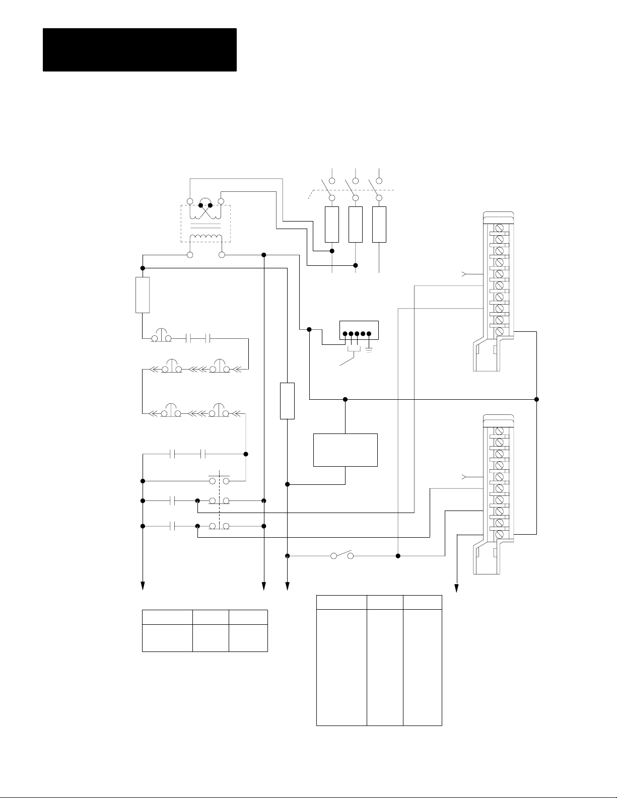
Chapter 6
Field Wiring Arm Connections
Figure 6.5
Grounded AC Power Connections, Crowbar T
est Inputs, and Press Interlock Switch
F
u
s
e
E-stop
H
E-stop
Station 2
E-stop
Station 3
Seal A
Crowbar A
Crowbar B
1
H
H
H
3
2
120V
AC
X
X
12
Customer
Contacts
E-stop
Station 1
E-stop
Station 4
Seal B
Start
4
Isolation/
Step Down
Transformer
Incoming
AC
L
Disconnect
F
u
s
e
1L1
To Motor Starters
Equipment
Grounding
Conductors
F
u
s
e
Processor
Power Supply
Crowbar A Test Input
Crowbar B Test Input
L
1
2
F
u
s
e
1L2 1L3
Back Panel
Ground Bus
To Earth
Ground
2L2
2L1
L
3
1771-IA
Module Group 2
Slot 0
F
u
s
e
3L1
A
0
1
2
3
4
5
6
7
B
2L2
Chassis A
A
0
1
2
3L1
3
4
5
6
7
2L2
B
616
3L1 3L2
odule group
M
3
4
120V AC Power for :
Slot
0
0
Figure
6.7
6.8
2L1
Press Interlock
120V AC Power for:
Module group
0
0
1
1
2
2
3
4
5
5
Slot
Chassis B
Figur e
0
1
0
1
0
1
1
1
0
1
6.10
6.11
6.12
6.9
6.5
6.7
6.14
6.8
6.8
6.13
2L2
12273
Page 69

Remove this jumper
when using Motion
Detector Switch B.
Chapter 6
Field Wiring Arm Connections
Figure 6.6
Connections for Optional Switches on Main V
Air Pressure Sensors, and Motion Detectors (Grounded AC Power)
1771IA
Module Group 2
Slot 0
Chassis A
A
0
1
2
3
4
5
6
7
B
A
Switches on
Auxiliary Valve
Stems
1
B
A
2L1
alve Stems,
Make this connection when using
Motion Detector Switch B.
A
Motion Detector(s)
B
A
2L1
Remove this jumper
when using Air Pressure
Switch B.
Chassis B
A
0
1
2
3
4
5
6
7
B
Switches on
Main Valve
1
Stems
2L1
Air Pressure Switch(es)
B
B
Make this connection when using
Air Pressure Switch B.
1
If
one or both valves have internal fault detection (no valve stem switches), but you
configured for valvestem feedback, then jumper terminals 0 and 7 in chassis A, and do
the same in chassis B.
2L1
12284
617
Page 70

Chapter 6
Field Wiring Arm Connections
Figure 6.7
Connections
for Main and Auxiliary Valve Solenoids, Crowbar and Seal Relays, and MOV
Surge Suppression (Grounded AC Power)
1771IA
Module Group 2
Slot 1
Chassis A
A
0
1
2
3
4
5
6
7
B
Chassis B
A
0
1
2
3
4
5
6
7
B
2L2
2L2
LRA
LRB
1
3L2
LRBLRA
1771OD
Module Group 3
Slot 0
Chassis A
1
2
3
4
5
6
7
8
9
10
11
12
Chassis B
1
2
3
4
5
6
7
8
9
1
0
11
12
Crowbar Relay
Seal Relay
3L1
Crowbar Relay
A
3
A
Seal Relay
3L2
B
A
3
Main
5
Valve
Solenoids
B
A
A
3
B
2
3
5
2
3
5
618
NOTES: Use this wiring with figure 6.5 for grounded AC power.
1
LRA and LRB load resistors for triac feedback are 2K ohm, 15 watt resistors
2
If auxiliary solenoids are not used, replace with 2K ohm, 15 watt resistors.
3
Each solenoid or relay coil should draw at least 60mA.
4
Connect one MOV between 3L1 and 3L2 for electrical noise suppression.
5
Connect one MOV to the 3L1 side of each solenoid load and to 3L2 for electrical noise suppression.
3L1
4
3L2
Auxiliary Valve Solenoids
17890
Page 71

3L1
Chapter 6
Field Wiring Arm Connections
Figure 6.8
Connections for Optional Dump and/or Microinch V
Suppression (Grounded AC Power)
For either option For optional Dump Valve For optional Micro-inch Valve
1771OD
Module Group 4
Slot 0
Chassis A
1
2
3
4
5
6
7
8
9
10
11
12
3L2
1
LRBLRA
1771IA
Module Group 4
Slot 1
LRALRB
A
0
1
2
3
4
5
6
7
B
Micro-inch Position
on Selector Switch
2L2 2L2
alve Solenoids with MOV Surge
1771IA
Module Group 5
Slot 0
Chassis A
A
Micro-inch
0
Valve Stem A
1
2
3
Pressure Sw. A
4
5
6
7
B
2L1
Dump Valve
Solenoids
B
A
2
3
A
2
3
3L2
Chassis B
B
Micro-inch Valve
Solenoids
Switches on
Dump Valve Stems
A
2L2
2L1
Chassis B
A
0
1
2
3
4
5
6
7
B
Micro-inch
Valve Stem B
Pressure Sw. B
2L2
17889
B
1
2
3
4
5
6
7
8
9
10
11
12
NOTES: Use this wiring with figure 6.5 for ungrounded AC power.
1
LRA and LRB load resistors for triac feedback are 2K ohm, 15 watt resistors
2
Each solenoid or relay coil should draw at least 60mA.
3
Connect one MOV to the 3L1 side of each solenoid load and to 3L2 for electrical noise suppression.
A
0
1
2
3
4
5
6
7
B
619
Page 72

Chapter 6
Field Wiring Arm Connections
Cam Limit Switches
Install two separate cam limit switch assemblies each with three cams and
three cam limit switches. Connect cam limit switches exactly as shown in
Figure 6.9. This allows each voting processor to monitor its own limit
switches for:
top-stop-check (TCAM)
run-on (RCAM)
anti-repeat (ACAM)
Each cam limit switch assembly must be independently driven by the
press shaft through a separate coupling device. Couple each cam limit
switch assembly to the shaft through a separate direct coupling, a separate
gear assembly, or a separate chain assembly.
WARNING: To guard against injury to personnel and
damage to your press, install two separate cam limit switch
assemblies that are independently driven by the press shaft
through separate coupling devices.
Two separate cam limit switch assemblies allow your clutch/brake
controller to stop press motion in case there is a failure within either cam
limit switch assembly or a breakage in either coupling device.
Set each pair of cam limit switches to similar settings as shown in
Figure 5.1. If the settings are not similar, the voting processors can
disagree on their perceived shaft zones and cause nuisance shutdowns.
We recommend the Allen-Bradley Rotating Cam Limit Switch (cat. no.
803-P3). This rugged duty cam limit switch assembly is well suited for
press applications. For ordering information, see the Allen-Bradley
Industrial Control Catalog or contact your local Allen-Bradley sales
engineer or distributor.
Because the Cat. No. 803-P3 is an industrial grade heavy-duty limit
switch, we recommend that it switch a power circuit drawing at least 0.25
Amp. Install a 470 or 500 ohm 50-watt load resistor in parallel with the
AC input to generate this current.
You need to mount the resistors on the subpanel to keep dissipated heat
(from resistors) away from modules, and because the resistor’s axial leads
are not compatible with the wiring arm.
620
Page 73

Chapter 6
Field Wiring Arm Connections
Cam Limit Switch
Assembly A
Cam Limit Switch
Assembly B
Figure 6.9
Connections
Topstopcheck (TCAM)
Run-On (RCAM)
Anti-Repeat (ACAM)
2L1
Topstopcheck (TCAM)
Run-On (RCAM)
Anti-Repeat (ACAM)
for Cam Limit Switch Assemblies
Chassis A
Chassis B
1771-IA
Module Group 1
Slot 1
A
0
1
2
3
4
5
6
7
B
A
0
1
2
3
4
5
6
7
B
[1]
2L2
[1]
2L2
2L1
[1]
470 ohm 50 watt 1%, or 500 ohm 5% on seperate terminal strip.
+
-
+
-
12278
621
Page 74

Chapter 6
Field Wiring Arm Connections
Required Hardwire Inputs
This
Input
Mode Select (terminals 03)
Main Motor Forward (terminal 4) Inch or
Connect hardwire inputs in parallel to chassis A and B so each voting
processor can monitor the following inputs in parallel:
Input Terminal MG Slot Figure
Mode
Select Switch
Main Motor Forward
Barrier Guard
Stopontop
Arm Continuous
Press Interlock
03
0
4
5
6
7
6
0
0
0
0
2
0
0
0
0
0
0
6.10
6.1, 6.5
When connected, these inputs function as follows:
With
PM in
this Mode
Determines
the mode
Microinch
W
ith this
Status
ON
ON or OFF
The PM module:
detects the selected mode
uses these signals to determine proper CAM action
Barrier Guard (terminal 5)
Arm Continuous (terminal 7)
Press Interlock (terminal 6)
chassis A & B MG 2, Slot 0
Single stroke
and
Continuous
Continuous OFF
Continuous,
only
any ON
ON
if turned OFF
after motion
has started
momentary
(less than 3 sec)
if turned OFF
WARNING: To guard against injury to personnel, wire you
barrier guard switch exactly as shown in Figure 6.10.
Conform to all requirements for safeguarding the point of
operation of your press as detailed in OSHA Regulations,
Title 29-Labor, Chapter XVII, Section 1910.217.
detects one of the permissives to start or maintain a stroke
immediately turns OFF solenoid outputs
prevents press from starting, or stops it immediately
Each ON/OFF transition starts a 5sec period in which you must
press all
Pressing Arm Continuous again within 5 seconds starts another
5sec period.
detects one of the permissives to start or maintain a stroke after
transition
immediately stops the press, or prevents it from starting
active RUN buttons to start continuous stroking.
622
Page 75
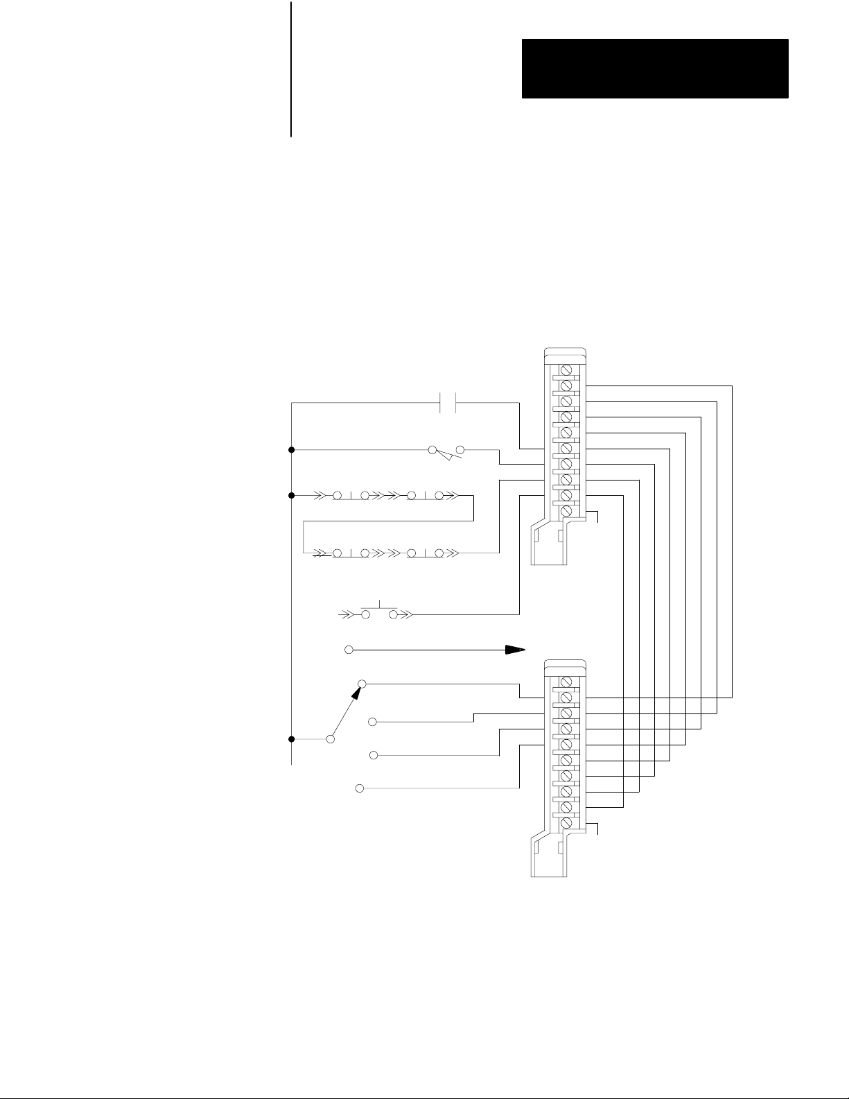
Chapter 6
Field Wiring Arm Connections
If you have more than one operator station, connect the STOP-ON-TOP
buttons in series.
Figure 6.10
Connections
for Main Motor Forward, Barrier Guard, Stop on Top, Arm Continuous, and
Mode Select Switches
Main Motor Forward
Barrier Guard
Station 1 Station 2
Stop-on-top
Station 3 Station 4
Arm Continuous
2L1
[1]
Station
MICRO-INCH (figures 6.4 and 6.8)
1771IA
Module Group 0
Slot 0
Chassis A
A
0
1
2
[1]
3
4
5
6
7
B
2L2
Off
Mode
Select
Inch
Single Stroke
2L1
[1]
This normally open limit switch must be closed
for continous operation.
Continuous
Chassis B
A
0
1
2
3
4
5
6
7
B
2L2
12279
623
Page 76

Chapter 6
Field Wiring Arm Connections
Inch Buttons and PlugIn
Operator Stations
Connect the (NC) and (NO) contacts of each INCH button to opposite
chassis exactly as shown in Figure 6.11. This allows both voting
processors to monitor and cross check both INCH buttons for correct
operation. You may locate the INCH buttons at an operator control panel.
However, they are not part of any plug-in operator station. Wire them
directly as shown in Figure 6.11.
Plug-in operator stations 1 thru 4 and dummy plugs that you may use to
bypass these stations are shown in Figure 6.11 and Figure 6.12. You may
alter this configuration according to the number of bypassable stations
that you need for your press system.
If all run stations are bypassed, you may still operate in inch or micro-inch
mode using INCH buttons.
For example, if you have only one operator station, you may wire station
1 as shown in Figure 6.11, using direct wiring instead of operator station
plug connections. However, you must also bypass station 2, using direct
wiring instead of dummy plug connections. In other words, to bypass
station 2, you may simply connect terminals 3 and 4 of each field wiring
arm to 2L1.
For another example, if you have three operator stations, and only station
2 will be in constant use, build and wire plug-in stations 1 and 3 as shown
in Figure 6.11 and Figure 6.12. Directly wire station 2 according to
Figure 6.11. Directly wire station 4 bypass according to Figure 6.12. You
must also build and wire the dummy plugs for stations 1 and 3.
Important: Configure or do not configure stations 3 and 4 through
backplane switch settings as described in chapter 3 and PLC configuration
bits as described in chapter 4. If you configure plug-in station 3 and/or
station 4, but do not use either or both, you must bypass the unused
station(s) with a dummy plug(s). If you have not configured for stations 3
and 4, you need not place a 1771-IA module in module group 1, slot 0,
chassis A and B.
Connect the (NC) and (NO) contacts of each RUN button to opposite
chassis exactly as shown in Figure 6.11 and Figure 6.12 for all stations.
This allows both voting processors to monitor and cross check all RUN
buttons for correct operation.
624
Page 77

Chapter 6
Field Wiring Arm Connections
Figure 6.11
Connections
Dummy Pl ug
for Station
Bypass
for Operator Stations 1 and 2, Dummy Plugs, and Inch Pushbutton Switches
1771IA
Left Run
Left Active
Left 2L1
Right Run
Right Active
Right 2L1
Stop-On-Top
E-st op
Plug-in
Operator
Stati on 1
Left Run
Left Active
Left 2L1
Right Run
Right Active
Right 2L1
Stop-On-Top
E-st op
0
Ch A-
1
Ch B-
2
Ch A-
Ch B
-0
Ch A-
1
Ch B-
2
Seefigure6.10
See figure 6.1 or 6.5
3
Ch A
4
Ch B-
5
Ch A-
3
Ch B-
4
Ch A-
5
Ch B-
Seefigure6.10
See figure 6.1 or 6.5
2L1
2L1
Module Group 0
Ch A
-
0
Ch A
-
1
Ch A
-
2
Ch A
-
3
Ch A
-
4
Ch A
-
5
Chassis A
Ch B-
0
Ch B-
1
Ch B-
2
Ch B-
3
Ch B-
4
Ch B-
5
Chassis B
Left
Inch
Slot 1
A
0
1
2
3
4
5
6
7
A
0
1
2
3
4
5
6
7
Right
Inch
2L2
2L2
B
B
Dummy Pl ug
for Station
Bypass
IMPORTANT:
Plug-in
Operator
Stati on 2
For These Connections
E - STOP
STOP-ON-TOP
Plug either the operator station
or dummy plug into the control panel.
See Figures
6.1 or 6.5
6.10
2L1
17879
625
Page 78

Chapter 6
Field Wiring Arm Connections
Figure 6.12
Connections for Operator Stations 3 and 4, and Dummy Plugs
Dummy Plug
for Station
Bypass
Left Run
Left Active
Left 2L1
Right Run
Right Active
Right 2L1
Stop-On-Top
E-stop
Plug-in
Operator
Station 3
Left Run
Left Active
Left 2L1
Right Run
Right Active
Right 2L1
Stop-On-Top
E-stop
Ch A-0
Ch B-1
Ch A-2
Ch B-0
Ch A-1
Ch B-2
2L1
See figure 6.10
See figure 6.1 or 6.5
Ch A-3
Ch B-4
Ch A-5
Ch B-3
Ch A-4
Ch B-5
2L1
See figure 6.10
See figure 6.1 or 6.5
1771-IA
Module Group 1
Slot 0
Ch A-0
Ch A-1
Ch A-2
Ch A-3
Ch A-4
Ch A-5
Chassis A
Ch B-0
Ch B-1
Ch B-2
Ch B-3
Ch B-4
Ch B-5
Chassis B
A
0
1
2
3
4
5
6
7
B
A
0
1
2
3
4
5
6
7
B
2L2
2L2
626
Dummy Plug
for Station
Bypass
IMPORTANT:
Plug-i n
Operator
Stati on 4
For These Connections
E - STOP
STOP-ON-TOP
Plug either the operator station
or dummy plug into the control panel.
See Figures
6.1 or 6.5
6.10
17880
Page 79

Chapter 6
Field Wiring Arm Connections
Important: When mounting RUN and INCH buttons, ensure that:
all RUN buttons and both INCH buttons are either guarded or
flush-head pushbutton switches, such as Allen-Bradley Bulletin 800P
Palm Operated Pushbuttons. You can operate guarded buttons only by
reaching through their guard rings.
the distance between each left RUN or INCH button and its
corresponding right RUN or INCH button is great enough to allow
operation of both buttons only by both hands.
all RUN and INCH buttons are located at greater than minimum safe
distance from the point of operation of your press as specified in OSHA
Regulations, Title 29-Labor, Chapter XVII, Section 1910.217, and
ANSIB11.1, section 5.3 Formulas for calculating the minimum safe
distance are included.
Optional Binary Display
Optional Indicators
Use the optional diagnostic binary display shown in Figure 6.13 to
troubleshoot your press. Chapter 7 lists the diagnostic messages.
We recommend Allen-Bradley Small Pilot Lights, Transformer Type (cat.
no. 800T-PS16R) with 1771-OA Output Modules. You may order color
caps separately (red is standard):
Red
= cat. no. 800T
Green = Cat. no. 800T
Amber = cat. no. 800T
Blue = cat. no. 800T
White = cat. no. 800T
Clear = cat. no. 800T
N122R
N122G
N122A
N122B
N122W
N122C
You may also want to order Small Pilot Light Guards (cat. no.
800T-N226), to protect the caps against accidental breakage.
STOP-ON-TOP FAULT - tells an operator that the brake is faulty. If the
shaft overshoots the near top position in inch, single, or continuous mode,
both voting processors prohibit clutch actuation, and turn on this indicator.
(See Table 5.a and Figure 6.14)
RUN WINDOW - turns on when starting the press in these modes:
single-stroke: When both RUN buttons have been pressed at one
station, other active stations have 5 seconds to press their RUN buttons
as shown by this indicator.
627
Page 80

Chapter 6
Field Wiring Arm Connections
continuous: Each ON/OFF transition of the ARM CONTINUOUS
button starts a 5-second period in which you must press all active RUN
buttons to start continuous stroking as shown by this indicator.
Pressing the ARM CONTINUOUS button again within 5 seconds (after
the transition) starts another
Important: Press the momentary ARM CONTINUOUS button less than
3 seconds. Pressing it for a longer time may inhibit its function and
require you to release and press it again.
MICRO-INCH - turns on when voting processors detect an error in
micro-inch mode and display a diagnostic message code which is
displayed by means of the diagnostic message display. Use look-up table
7.C to determine the fault or error.
You can use the micro-inch output in two ways:
to turn on the MICRO-INCH indicator
to set the most significant bit in a 9-bit binary output.
Diagnostic codes for micro-inch mode are 9-bit binary (3-digit hex) with
1 as the first digit (Figure 6.14). Diagnostic message codes for all other
modes are 8-bit binary (2-digit hex). (Figure 6.13)
628
Page 81

Chapter 6
Field Wiring Arm Connections
Chassis A
Chassis B
Figure 6.13
Connections
1771-OA
Module Group 5
Slot 1
B
A
B
for Optional Diagnostic Message Display
A
0
1
2
3
4
5
6
7
0
1
2
3
4
5
6
7
We recommend Allen-Bradley Small Pilot Lights,
Transformer type (cat. no. 800T-PS16R).
2L1
Bit17Bit16Bit15Bit14Bit13Bit12Bit11Bit
2L2
2L1
Bit17Bit16Bit15Bit14Bit13Bit12Bit11Bit
10
10
2L2
12285
629
Page 82

Chapter 6
Field Wiring Arm Connections
Figure 6.14
Connections for Brake Fault, Run W
1771OA
M
odule Group 3
Slot 1
Chassis A
A
0
1
2
3
4
5
6
7
B
StopOnTop Fault
2L1
Run Window
Micro-Inch
indow
, and MicroInch Indicators
W recommend AllenBradley Small Pilot Lights,
Transformer type (cat. no. 800T PS16R).
2L2
Chassis B
A
0
1
2
3
4
5
6
7
B
2L1
Micro-Inch
2L2
12286
630
Page 83

Chapter 6
Field Wiring Arm Connections
Lamp Test
Inputs to Chassis C
When you configure the lamp test feature, you can check that all
indicators are working by pressing the LAMP TEST switch connected to
chassis C. The clutch/brake controller energizes the outputs to the
following indicators while the lamp test input is on:
Module Group 5, Slot 1, Chassis A and B for the diagnostic display
Module Group 3, Slot 1, Chassis A and B for BRAKE FAULT, RUN
WINDOW, and MICRO-INCH indicators.
Since hex (hexadecimal) numbers are easier than binary for people to
read, you may want to display hex message codes. You may provide a
device to convert the eight-digit binary outputs of chassis A and B,
module group 2, slot 1 to two-digit hex displays. Select output modules
that provide proper voltage to the device. For assistance, contact your
local Allen-Bradley sales engineer or distributor.
In chapter 7, we describe other methods of displaying hex message codes.
Chassis C provides for these functions:
reset latched messages
lamp test
customer interlock (redundant to Figure 6.1 or 6.5)
barrier guard (redundant to Figure 6.10)
stop-on-top (redundant to Figures 6.11 and 6.12)
This chassis is optional because you can:
omit redundant functions
use alternatives for the non-redundant functions
As alternatives, you can program the PLC to transfer the message reset bit
(bit 14) and/or the lamp test bit (bit 16) to the clutch/brake modules to
provide those functions. If already using A-B’s PanelView
, use that
operator interface to implement these functions.
If you use chassis C, follow these steps:
1. Wire PLC command switches as shown in Figure 6.15
2. Include command rungs, Figure 4.6, 4.7, or 4.8.
3. Set the backplane switches of chassis C to a valid rack address for
your PLC and clutch/brake system.
631
Page 84

Chapter 6
Field Wiring Arm Connections
Chassis C can be any remote or local I/O chassis connected to your PC.
Refer to sections titled “Panel Switches and Operator Stations”in chapter
3, and “Configuration Rungs” in chapter 4, for additional information.
Figure 6.15
Connections
2L1
Customer Interlock
for Optional PLC Command Switches
1
Chassis C
(Remote I/O Chassis)
1771-IA AC Input Module
Rack 3, Module
Group 2
Bits 10 thru 17
A
0
Barrier Guard
Bit 13
Bit 14
Reset Latched Messages
Bit 15
Bit 16
Stop-On-Top
Lamp Tes
1
To write the ladder program to implement the use of these switches, refer to
t
1
2
3
4
5
6
7
B
Figure 4.6, Figure 4.7 or Figure 4.8.
2L2
632
12287
Page 85

Troubleshooting
Chapter
7
Chapter Objectives
Troubleshooting Considerations and Requirements
After you have read all previous chapters, this chapter can help you:
safely isolate and correct problems in your press system
interpret diagnostic messages generated by your clutch/brake controller
use the module indicators in chassis A and B while troubleshooting your
press system
This chapter explains troubleshooting techniques and refers to previous
chapters. We recommend that you read the entire manual and all technical
documentation provided by the press manufacturer before troubleshooting
any problem with your press system.
We also recommend that you adhere to the safety requirements detailed in
local code and laws and in the following publications:
OSHA Regulations, Title 29-Labor, Chapter XVII, Section 1910.217,
Mechanical Power Presses
ANSI B11.1, American National Standard for Machine Tools,
Mechanical Power Presses, Construction, Care, and Use
NFPA No. 79, Electrical Standard for Metal working Machine Tools
Troubleshooting with LED's
Familiarity with this documentation makes your troubleshooting not only
safer, but easier as well.
Use these figures and tables when troubleshooting with LED indicators
Reference Description
7.1
Figure
Figure 7.A
Figure 7.B
Figure 7.2
Location of LED indicators
How to read the PM Module'
How to read the PM Module'
CBM F
AUL
T indiators
How to troubleshoot with LED indicators
s ACTIVE indicator
s I/O RACK F
AUL
T and
71
Page 86

Chapter 7
Troubleshooting
Figure 7.1
Indicators for Chassis A or B
Module
Input Module Indicators
Input status indicators are clear. On = input
One indicator per terminal.
PM Module Indicators
ACTIVE
(green)
CBM
FAULT
(red)
I/O RACK
FAULT
(red)
Refer to tables 7.A and 7.B
1771-PM Module 1771-IA Modules
Output Module Indicators
Output status
indicators are red.
On = output
Blown fuse
indicators are clear.
On = blown fuse
1771-OD Module
Table 7.A
ACTIVE Indicator
If the ACTIVE indicator is blinking, identify the problem by the number of blinks. There are 2 sets of blinks:
first set of blinks short pause second set of blinks long pause
repeat continuously
12292
Number of Blinks
1st Set
1 3
1 4
2 1
2 3
3 2
3 4
4 1
4 3
72
2nd Set
Problem Correction
Faulty RAM
Faulty PROM
Illegal rack address
The 1771PM modules contain dif
ferent firmware
Missing a 1771PM module at power up
Illegal interrupt
Replace 1771PM module
Replace 1771PM module
Set the 1771PM module switches as detailed in chapter 3
Install 1771PM modules with identical revision codes
Install and fully seat both 1771PM modules
Cycle power Replace 1771PM module
Firmware fault Replace 1771PM module
Lost communications between 1771PM modules,
or watchdog timed out
Check connections between 1771PM modules or
Replace 1771PM module
Page 87

Table 7.B
I/O RACK F
AUL
T and CBM F
AUL
T Indicators
Chapter 7
Troubleshooting
I/O RACK
FAULT
CBM
FAULT
On Off
On
or OFF
Press will not run.
Is a diagnostic
message displayed
Are all status indicators for
inputs to the 1771IA module
off? (See Figure 7.1)
Is the mode select switch off?
Problem Correction
Intermittent electrical noise, faulty 1771PM
module, or shorted I/O chassis backplane
Intermittent electrical noise or faulty 1771PM
On
module
Figure 7.2
roubleshooting Flowchart for Module Indicators
T
Yes
Yes
No
Yes
No No
Go to table 7.C.
All power is off.
(See figure 6.1 or 6.5)
Select proper
mode.
Cycle power
Replace 1771PM module
Replace each I/O module one at a time
Replace I/O chassis
Cycle power
Replace 1771PM module
Does the
press run?
Yes
Resume
normal
operation.
Check the 1771PM module indicators. (See figure 7.1)
Are both ACTIVE indicators on?
No
Is either ACTIVE indicator blinking?
No
Is either I/O RACK FAULT indicator on?
No
Is either CBM FAULT indicator on?
No
Replace the 1771PM module whose ACTIVE indicator is off, or check the chassis
power supply.
[ 1 ] The controller will not operate if you manually configure chassis A and B to a half rack
Warning: To guard against injury to personnel, open and lock the main power disconnect before adjusting, replacing, or repairing any
mechanical or electrical component in your press system. This consists of the press, clutchbrake, controller, and all associated wiring and
control panels.
Yes
Are rack addresses, rack
size [1], and/or baud rate
set correctly?
Yes
Yes
Yes
Press should run. Refer to press
builder's documentation.
Go to table 7.A
Go to table 7.B
12290
73
Page 88

Chapter 7
Troubleshooting
General Troubleshooting Procedure
Although the procedure for troubleshooting your clutch/brake controller
varies with each problem, use the following steps as a general procedure:
1. Examine Figure 7.2 and NO TAG.
2. Answer questions in Figure 7.2 and NO TAG until you see a
reference to another figure or table. Table 7.C lists diagnostic codes.
3. Place a bookmark at Figure 7.2 or NO TAG and go to the figure or
table that it referred to in step 2. That figure or table might contain
other references. Therefore you may need several bookmarks while
working among various figures and tables throughout this manual.
Table 7.D is your primary reference.
4. Isolate the problem using the guidelines in Figure 7.2, or NO TAG,
Table 7.C, and other references.
5. Correct the problem.
Troubleshooting Hints
WARNING: To guard against injury to personnel or damage to
your press, open and lock the main power disconnect to turn off
all AC and DC power before:
manually turning the press shaft
adjusting or repairing any moving parts in your press
repairing or replacing any wiring in your press system,
including any field wiring arm or cable connections
replacing any electronic or electrical components, such as
clutch/brake controller and I/O modules, power supplies, or
chassis
replacing blown fuses in your press system
Diagnostic codes are specific and point to the exact input or output device
that controls PM operation. When your system is wired as outlined in this
manual, you can identify the cause of a fault as follows:
1. Review the section “Diagnostic diagnostic message codes”, below.
74
2. Note the diagnostic code for both
PM modules
Page 89

Press will not run.
Chapter 7
Troubleshooting
3. Determine the input or device causing the fault from the
section/sub-section heading in Table 7.D where the fault code was
tabulated and from other figures or tables referred to.
4. Interpret the messages. Was this output supposed to be on? Was that
device supposed to be off?
Figure 7.3
Troubleshooting
Flowchart for Diagnostic diagnostic message codes
Is a diagnostic message
displayed?
Yes
See Table 7.C
Does the problem relate to an
input switch or connection?
Does the status indicator for the
input to the 1771IA module
respond correctly? (See Figure
7.1)
Yes
No
No
No
Go to figure 7.2
Does the problem relate to a
solenoid or its triac?
Yes
Is a blown fuse indicator on for
any 1771OD module? (See
Figure 7.1)
Yes
Replace the fuse.
Replace the input switch or
check its wiring.
No
No
Take action according to Table
7.C
Replace the 1771OD module or
the solenoid. Check solenoid
wiring.
Replace the 1771IA module.
Warning: To guard against injury to personnel, open and lock the main power disconnect before adjusting, replacing, or repairing any
mechanical or electrical component in your press system. This consists of the press, clutchbrake, controller, and all associated wiring and
control panels.
12291
75
Page 90

Chapter 7
Troubleshooting
5. Trace wire leads and/or inspect the faulted device.
If you wired the PM system in a manner other than outlined in this
manual, faults are more difficult to track. Proceed as follows:
1. Determine if the fault and corresponding diagnostic code was caused
by alterations in system wiring, i.e., if the fault is a run station fault,
are the run stations wired directly to the PM system or through
auxiliary chassis controlled by the programmable controller? If the
latter is the case, you should look at the programmable controller’s
ladder program.
2. Determine if you have an I/O problem. The PM module can only
diagnose its own I/O level. That is, it alerts you to the exact input or
output within the system that it “sees” as incorrect. You must
interpret from there.
Troubleshooting Example
Assume that your press is running normally, then stops suddenly. For this
example, we will follow the general troubleshooting procedure.
1. Examine Figure 7.2 and Figure 7.3.
2. The first question asked in both figures is whether a diagnostic
message is displayed. For this example, we assume that chassis A
and B are displaying these diagnostic messages:
chassis A 0010 1001 (hex 29)
chassis B is displaying 0010 1000 (hex 28)
Because your answer is yes, see Table 7.D to define the problem.
3. In Table 7.D you find that:
Binary 0010 1001 (hex 29) is a T-type (trip condition) message that
tells us: Station 1 active connection is open (for alternate chassis).
Check wiring. (figure 6.11).
Since chassis A is displaying this message, the alternate chassis is
chassis B.
Binary 0010 1000 (hex 28) is the same message. It is for the
chassis displaying the message, chassis B in this case.
76
Page 91

Chapter 7
Troubleshooting
In Table 7.C, the numbers in parentheses are figure references. In
this example, both messages refer to Figure 6.11. Therefore, place a
bookmark at Table 7.D and go to that figure.
4. Figure 6.11 shows station 2 active connections for both chassis:
Left Active connects to terminal 5 of field wiring arm for module
group 0, slot 1 in chassis A.
Right Active connects to terminal 5 of field wiring arm for module
group 0 slot 1 in chassis B.
Since you learned in step 3 that the problem relates to chassis B, you can
concentrate on the Right Active connection.
5. To further isolate the problem, place a bookmark at Figure 6.11 and
return to Figure 7.3. The next question in this figure asks: Does the
problem relate to an input switch or connection? In this example,
your answer is yes, which leads you to another question. Does the
status indicator for the input to the 1771-IA module respond
correctly? (See Figure 7.1).
6. Figure 7.1 shows you where to find the input status indicators. For
this example, assume that the input status indicator in chassis B for
module group 0 slot 1, terminal 5 is off.
As shown in Figure 6.11, the Right Active connection is jumpered as
long as Plug-In Operator Station 2 is plugged in. Therefore, the
indicator for Right Active should be on.
7. Return to NO TAG. Since this indicator is off, your answer is no to
the question: Does the input status indicator respond correctly?
NO TAG tells you to replace the input switch or check its wiring.
8. Correct the problem after first opening and locking the main power
disconnect. Inspect and test the Right Active connection (Figure
6.11). For this example, you find a broken wire in Plug-In Operator
Station 2. Repair the broken wire then, close the main disconnect and
return the press to normal operation.
77
Page 92

Chapter 7
Troubleshooting
Display of Diagnostic Message Codes
When the PM module detects a condition, it immediately generates the
corresponding message code. You can display diagnostic message codes
with an optional display device connected to output modules in these
locations in chassis A and B:
module group 5, slot 1 (8-bit binary code)
module group 3, slot 1, bit 2 (9th bit for micro-inch)
When using micro-inch mode, diagnostic diagnostic message codes are
9-digit binary (3-digit hex) rather than 8-digit binary (2-digit hex) for
other diagnostic message codes. The most significant bit (bit 9) indicates
a micro-inch code. When set, 2-digit hex codes XX become 3-digit hex
codes 1XX for micro-inch.
You can display diagnostic message codes in 9-digit binary, or use an
optional binary-to-hex converter and display diagnostic message codes in
easy-to-read hexadecimal notation. No programming is required. Just
install output modules in those locations and connect display devices
(Figures 6.13 and Figures 6.14).
You can also view diagnostic message codes with an Allen-Bradley
programming or display terminal using the data monitor feature:
If
using this
processor
PLC2 family
PLC3 family
PLC5 family
PLC5/250
Use this device
Industrial T
Handheld T
Industrial T
Data access panel on the front of the processor or
1784T45, T47, or T50 Programming T
1784T45 ,T47, or T50 Programming T
1784T45, T47, or T50 Programming T
erminal (1770T3)
erminal (1770T1
erminal (1770T4)
1)
erminal
erminal
erminal
78
Page 93

Chapter 7
Troubleshooting
Types of Diagnostic Message Codes
PM modules detect operational and equipment faults, and indicate
corresponding diagnostic message codes for more than 250 detected
conditions. Diagnostic diagnostic message codes refer to specific inputs
or outputs, such as a contact on a switch or cam. Upon detecting a
condition, each PM module generates its own diagnostic code. Quick
succession of events may cause each PM module to detect a different
condition, one condition resulting from the other.
PM modules generate three types of diagnostic message codes according
to the severity of the condition:
Code Type Priority Method
N nonlatched least
L latched moderate
L latched
followed by "0D"
moderate
of reset
Clears itself when conditions no longer exist
Correct the condition
Press the RESET LA
Correct the condition
Restore power
Inch the press to neartop position
Push the RESET LA
Press the ST
TCHED MSG pushbutton
TCHED MSG pushbutton
AR
T button
T tripped highest
Correct the condition
Press the RESET LA
Press the ST
AR
T button
TCHED MSG pushbutton
Nonlatched Messages (lowest priority)
Non-latched messages occur when the PM module detects an error
condition while the press is idle (clutch/brake solenoids are OFF) and the
control seal relays are either open or closed. The PM module:
prevents press operation as long as the error is present
After you correct the error conditions, the PM module automatically clears
the message and readies itself for operation. These messages are typically
related to a wiring error or equipment malfunction.
Example: A broken or loose wire on the active line of Run Station 1
(Figure 6.13) could cause the PM module to generate the following
message code:
Error 10 (Hex)
Check RUN button signals. Activate or bypass the station.
79
Page 94

Chapter 7
Troubleshooting
Latched Messages (medium priority)
Latched messages occur when the PM module detects error conditions
while the press is running (clutch/brake solenoids are ON). The module:
stops press motion immediately
latches ON a diagnostic message
turns OFF solenoid valve triacs
(seal relays remain closed)
The latched-message condition remains until you correct the problem and
press the RESET LATCHED MSG pushbutton wired to chassis C.
Typical error conditions are equipment failures or improper mechanical
adjustments.
Example: If the barrier guard switch should open while the press is
running in continuous mode, the PM module would immediately turn OFF
the solenoid valve triacs and generate the following message code:
Error 09 (Hex)
Barrier guard dropout or absent
Latched Messages Followed by 0D" (corrective intervention)
Whenever a diagnostic message code is followed by the ”0D” message
code, the maintenance technician must reset the PM system by removing
control power, and then re-applying power. This forces the technician to
correct the problem before press operation can continue.
Standard Corrective Action
Because the ”0D” message code accompanies a variety of other diagnostic
message codes, we recommend a standard corrective action. Use it when
correcting faults for “OD” diagnostic message codes presented in Table
7.C.
Check for proper cam setting and operation.
(Refer to Figure 5.1 in this manual.)
Check for bad or frozen cam contacts
If more than one cam assembly is used for multi-speed press operation,
check switching of these cams.
Check for proper wiring of cam switches.
Check for proper wiring of I/O module swing arms.
710
Page 95

Chapter 7
Troubleshooting
Restarting the Press
You re-start the press with this procedure:
1. When the “OD” message is displayed, press ESTOP to drop the seal
relays.
Message code “50” is displayed (swingarm power dropout)
2. Press the START button.
3. Press the RESET LATCHED MSG button.
4. Select INCH mode if not already selected.
5. Inch the press to the near-top position.
Types of OD" Diagnostic Message Codes
The “OD” diagnostic message code accompanies the following type of
diagnostic messages.
Type of Message Hex Code
Downstroke 066 067
Upstroke 068 069
Brake or Motion Detector 072 079, 07A
Cam Limit Switch
Near Top Position
Transition to Downstroke
Downstroke
Transition to Near Bottom Zone
Near Bottom Zone
Transition to Upstroke
080 085
086 089
08A 08F
090 093
094 099
09A 09D
Upstroke
Transition to Near Top Position
Hardware or Cable 0F1 0F3
09E 09F, 0A0 0A3
0A4 0A7
711
Page 96

Chapter 7
Troubleshooting
Tripcondition Message (highest priority)
Trip-condition messages occur anytime the PM module detects a fault
condition that casts doubt on the system’s ability to:
measure the press’s shaft angle
control power to the solenoid valve triacs
When it detects this type of fault, the PM module immediately:
stops press motion
opens the seal relays
If it detects that the seal relays did not open, it
blows the main power fuses with crowbar relays
The trip-condition fault remains until you correct the problem and press
the RESET LATCHED MSG pushbutton wired to chassis C. Typical fault
conditions are due to system configuration, feedback signals, run stations,
or triacs. After corrrecting the fault condition, get back into operation
with the same steps as 0D Latched Message, above.
Messagecode Priority
Example: If the motion detection input (Figure 6.2) should turn ON
while the press is operating, and you did not configure for motion
detection, the PM module would generate the following message:
Error BB (Hex)
Motion detector signal present though motion detector feedback is
not configured.
Diagnostic diagnostic message codes are not queued. When the PM
module detects multiple latched or tripped message conditions, it sends the
highest priority message code to the processor so your ladder logic can
process it, and to pre-determined slots in its I/O chassis so output modules
can display it. When you correct the condition and press the MESSAGE
RESET button, the PM module sends the next highest priority message
code if an error condition still exists. A message code of higher priority
overrides a message code of lower priority. For error conditions of equal
priority, the PM module sends the message code corresponding to the first
detected condition.
712
Page 97

Chapter 7
Troubleshooting
Processing Diagnostic Message Codes
If you want to maintain a record of diagnostic message codes or process
them for reasons other than display, you can write ladder logic to examine
the 9-bit binary message code that PM modules return to the processor.
Do this by examining bits in the input image table corresponding to:
module group 5, slot 1 (8-binary code)
module group 3, slot 1, bit 2 (9
th
bit for micro-inch)
For example, examine a bit as follows:
I:r5
||
16
where r is the I/O rack number
If recording a history of diagnostic message codes such as stored in a
FIFO stack, we suggest that you record only diagnostic message codes that
exist for longer than one second and disregard all diagnostic message
codes resulting from transient conditions of shorter duration. This guards
against storing no-fault status diagnostic message codes such as generated
during start-up.
Diagnostic Message Codes (Table 7.C)
Table 7.C explains message codes generated by PM modules.
For each message code, the table states:
type of diagnostic message
the problem causing the diagnostice message to be displayed
recommended corrective action
In Table 7.C we use mnemonics for cam switches for the sake of brevity as
follows:
ACAM: anti-repeat cam switch
RCAM: run-on cam switch
TCAM: sto-top-check cam switch
713
Page 98

Chapter 7
Troubleshooting
Table 7.C
Diagnostic
MISCELLANEOUS MESSAGES
HEX
CODE
01 N IMPROPER MODE SELECTION
02 N ALL STATIONS BYPASSED
03 N SHAFT NOT AT TOP. CAN NOT ENTER SINGLE OR
TYPE PROBLEM CORRECTIVE ACTION
The PM module expects to see one of the allowable press
modes (off, inch, microinch, single, continuous, within 0.1 sec's
after swingarm power is sealed in, and will only allow one mode
at any given time.
In the single stroke or continuous mode, the PM will not allow the
press to cycle if all operator run stations are bypassed. At least
one station must be present. Inch and microinch modes will
operate with all run stations bypassed.
CONTINUOUS MODE
The PM is selected to go into the single or continuous mode, but
the cam switches, which indicate shaft position, are telling the
PM that the press is not at the top.
Message Codes Associated with the "0D" Message Code
Check selector switch wiring in figure 6.10 and operation.
Check wiring to swingarm. Check I/O module for correct
operation.
Check station wiring in figures 6.11 and 6.12. Check
swingarm wiring and I/O module for proper operation.
Check for proper cam settings in figure 5.1. Check for
proper cam wiring in figure 6.9. Inch press to the top
position.
04 N AWAITING RELEASE OF ALL RUN BUTTONS FOR ENTERING
SINGLE OR CONTINUOUS MODES
05 N/L MAIN MOTOR FORWARD CONTACT DROPOUT OR ABSENT
The main motor forward input needs to be on in order to enter
single or continuous modes. Once in single or continuous mode,
the press will stop if that input goes off.
06 N ACAM OPEN, PREVENTING ENTRY INTO SINGLE OR
CONTINUOUS MODE.
07 N AWAITING RELEASE OF ALL STOPONTOP BUTTONS FOR
ENTERING CONTINUOUS MODE.
You must release STOPONTOP buttons of all active stations
before the PM can switch to another mode of press operation.
08 N AWAITING RELEASE OF ARM CONTINUOUS BUTTON FOR
ENTERING CONTINUOUS MODE.
You must release the ARM CONTINUOUS button and press the
RUN buttons of all active stations before the PM can switch to
continuous mode.
09 L BARRIER GUARD DROPOUT OR ABSENT.
Press stops operation.
Release all run buttons. Check for proper operation of all
buttons. Check button wiring in figures 6.11 and 6.12.
Check feedback contact and wiring in figure 6.10. Check
swingarm wiring and I/O module for proper operation.
Check wiring of ACAM in figure 6.9 and check ACAM
position in figure 5.1.
Check RUN button wiring figures 6.11 and 6.12.
Check ARM CONTINUOUS button wiring figure 6.10.
Check for faulty switch, broken wire, etc. figure 6.10.
714
Page 99

MISCELLANEOUS MESSAGES (cont'd)
Chapter 7
Troubleshooting
HEX
CODE
0A N/L PC ENABLE DROPOUT OR ABSENT
0B N STOPONTOP SIGNAL FROM PC PREVENTING ENTRY TO
0C N AWAITING RELEASE OF INCH BUTTONS FOR ENTERING
TYPE PROBLEM CORRECTIVE ACTION
*LATCHED MESSAGE
The PC enable bit from the processor must be maintained to the
PM while in any mode other than off. The PM must also see the
PC enable bit maintained while switching to off mode.
*NON LATCHED MESSAGE
The PM must first see the PC enable bit go on before it sees any
request to change modes. If this does not happen, this message
will occur.
CONTINUOUS MODE.
PM module is still receiving STOPONTOP command from the
PC processor. This command must be absent before PM can
enter continuous mode.
INCH MODE.
Inchbutton inputs must indicate that both
been released, then pushed again before its PM Module will
allow inching motion. This is the antetiedown feature of the PM
Module. refer to figures 5.2 and 6.11.
inch buttons have
When the PM is actually in the off mode, the PC enable bit
may be turned off.
This condition should be used as a status prompt that
indicates the user program has not given final permission
to enter the selected mode. Check programming in
figure4.6.
Check ladder logic (figure 4.6, 4.7, 4.8).
Refer to figure 5.2. Check wiring in figure 6.11.
0D N
0E N PC RUN MODE DROPOUT OR ABSENT
PC processor is not in RUN mode, probably due toa processor
fault.
0F N PRESS INTERLOCK DROPOUT OR ABSENT Check wiring of press interlock switch in figure 6.1 or 6.5.
10 N CHECK RUN BUTTON SIGNALS. MAKE STATION ACTIVE OR
BYPASSED.
15 N MAKE LEFT AND RIGHT ACTIVE CONNECTIONS IDENTICAL. Check station #1 (figure 6.11).
Correct processor fault. Switch to RUN mode.
The cactivestation input is absent, but the PM module is
detecting a changeofstate of operator RUN buttons.
Check station #1 (figure 6.11).
715
Page 100

Chapter 7
Troubleshooting
STATION MESSAGES
HEX
CODE
6A N AWAITING RELEASE OF ALL ACTIVE RUN BUTTONS"
TYPE PROBLEM CORRECTIVE ACTION
OCCURS UNDER THE FOLLOWING CONDITIONS:
1. If after pressing 1 active run button and then not pressing all
active run buttons within 5 seconds. After an additional 5
seconds the message will occur.
2. During single stroke mode and at the end of a normal stroke,
the PM is looking for all active run buttons to be released within
1 second of deenergizing clutch valve outputs.
3. After the arm continuous button is released, if all
active station run buttons are not released within 0.1 second.
IN GENERAL, THESE MESSAGES OCCUR TO PREVENT THE
FOLLOWING:
1 ANTITIE DOWN The PM requires that both buttons be
released if both were pressed and then one has been
released. There is no time delay for this condition to cause a
trip message. The PM also requires that once one button is
pressed, the other button needs to be pressed within 0.5
seconds to continue to operate without a problem.
2. Indication of change in the station active/bypass state or
nc/no contact wiring.
Check for proper wiring of station run buttons. Check for
proper operation of run button contacts.
6B N AWAITING RELEASE OF BOTH INCH BUTTOns. You must press, release, and press again both INCH
buttons before PM can allow further press motion.
6C N AWAITING RELEASE OF ARM CONTINUOUS BUTTON. After releasing the ARM CONTINUOUS button, you have 5
seconds to press all RUN buttons before the PM can enter
continuous mode.
6D N CONTINUOUS CYCLE NOT ARMED. You cannot enter continuous mode until you press the
ARM CONTINUOUS button. You must release it before
pressing all RUN buttons within 5 seconds.
6E N AWAITING PC TO INHIBIT STOPONTOP SIGNAL. The PM module is still receiving the STOPONTOP
command. It must cease before the PM can enter
continuous mode. Check your ladder logic (figure 4.6, 4.7,
or 4.8).
6F N AWAITING RELEASE OF ALL STOPONTOP BUTTONS. You must release the STOPONTOP buttons of all active
stations before the PM can start any press motion resulting
from pressing RUN buttons.
716
 Loading...