

Page 1
Installation Instructions
AC (120/220V) 16A
Power Supply
(Cat. No. 1771-P7 Series C)
To the Installer
Compliance to European Union Directives
This document provides you with the following information:
For this information See page
compliance European Union Directive
preparing to install the power supply 2
installing the power supply 3
connecting ac power to the power supply 7
troubleshooting 8
specifications 9
power ratings 9
The series C version of this product is marked with the
indicating that this version complies with the European Union
Directives noted below.
If this product has the CE mark it is approved for installation within
the European Union and EEA regions. It has been designed and
tested to meet the following directives.
1
logo,
EMC Directive
This product is tested to meet Council Directive 89/336/EEC
Electromagnetic Compatibility (EMC) and the following standards,
in whole or in part, documented in a technical construction file:
• EN 50081-2
EMC – Generic Emission Standard, Part 2 – Industrial
Environment
• EN 50082-2
EMC – Generic Immunity Standard, Part 2 – Industrial
Environment
This product is intended for use in an industrial environment.
Publication
17715.39 December 1995
Page 2

AC (120/220V) 16A Power Supply2
Low Voltage Directive
This product is also tested to meet Council Directive 73/23/EEC
Low Voltage, by applying the safety requirements of EN 61131–2
Programmable Controllers, Part 2 – Equipment Requirements
and Tests.
For specific information that the above EN requires, see the
appropriate sections in this publication, as well as the following
Allen-Bradley publications:
• Industrial Automation Wiring and Grounding Guidelines
(for noise immunity), publication 1770-4.1
• Guidelines for Handling Lithium Batteries, publication AG-5.4
• Automation Systems Catalog, publication B111
Prepare for Installation
The 1771-P7 power supply can power one 1771-A1B, -A2B, -A3B,
-A3B1, or -A4B I/O chassis when used with any adapter module or
programmable controller (Mini-PLC-2/02
Mini-PLC-2/16
that does not have an internal power supply.
Important: The power supply is not compatible with the 1771-A1,
!
!
, Mini-PLC-2/17, or PLC-5 family processor)
-A2, or -A4 I/O chassis.
ATTENTION: The 1771-P7 is a stand-alone
power supply. Do not connect it in parallel with any
other power supply. Connecting it in parallel could
result in processor memory loss or injury due to
unexpected machine operation.
ATTENTION: Under some conditions, electrostatic
discharge can degrade performance or damage system
components. Observe the following precautions to
guard against electrostatic damage:
, Mini-PLC-2/05,
• Touch a grounded object to rid yourself of charge
before handling a module.
• Do not touch the backplane connector or
connector pins.
• When not in use, keep modules in their
static-shield bags.
Publication
17715.39 December 1995
Page 3
AC (120/220V) 16A Power Supply 3
Before installing the power supply, you should:
• mount the I/O chassis that the power supply will be connected to.
See the Universal I/O Chassis Installation Data (1771-2.210) for
information on mounting the I/O chassis.
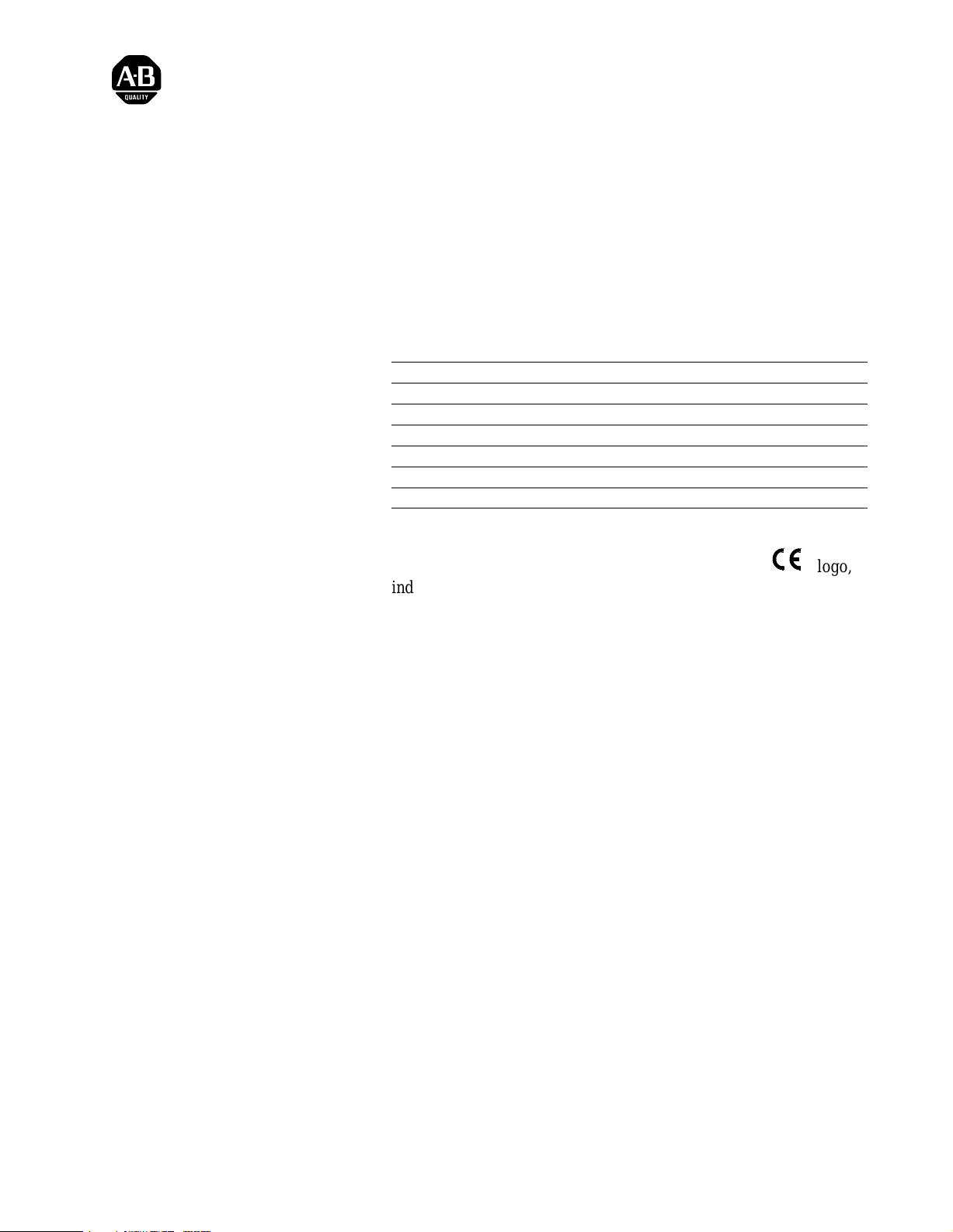
• set the power supply configuration jumper on the I/O chassis.
The 1771-P7 is an external power supply. Set the configuration
jumper to the N position.
NY
Using
Power
Supply
Module in
the Chassis?
Install the 1771P7 and
Connect Backplane Power
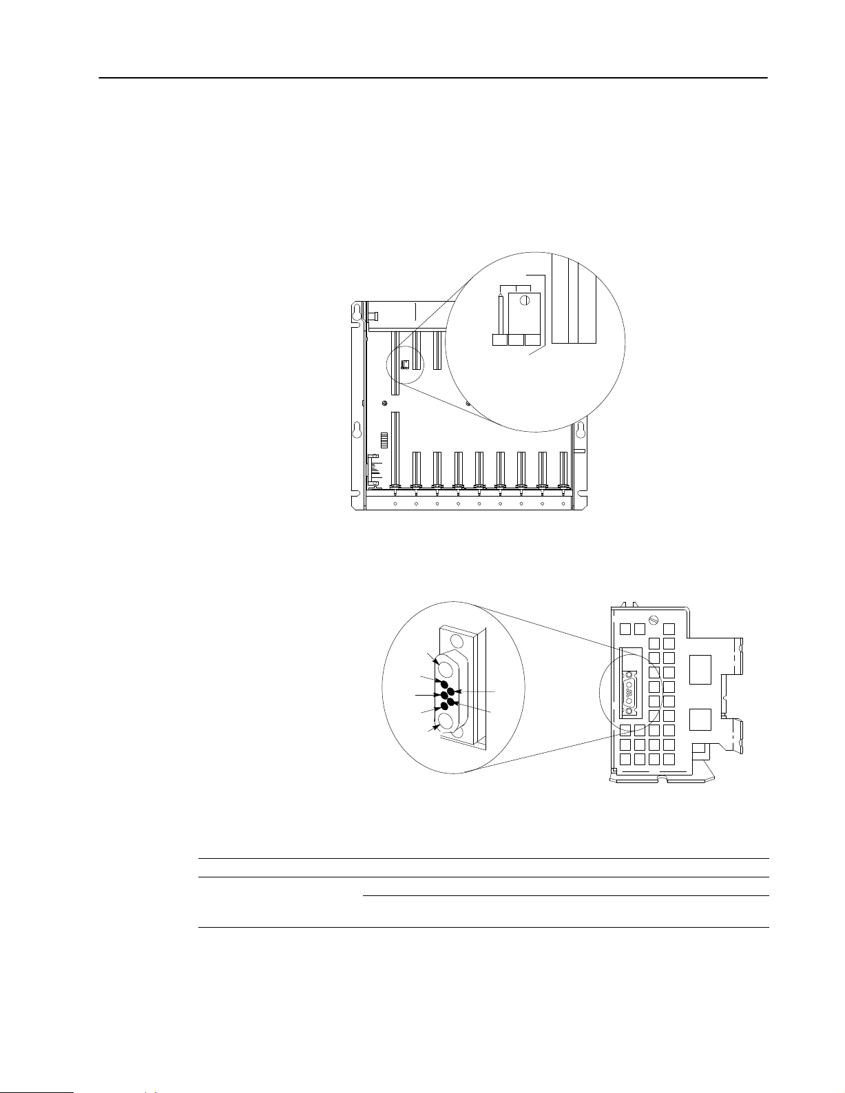
A1 backplane common
A2 backplane +5V dc
1 no connection
2 backplane processor enable
3 backplane +5V dc sense
4 backplane signal ground sense
5 no connection
If you have this I/O chassis Use this power cable To connect a 1771P7 mounted
1771A3B
1771A1B, A2B, A3B1, or A4B
The power supply has a D-shell power connector that provides
power to the I/O chassis backplane.
A1
3
4
5
A2
1771CP2 within 1.52m (5ft) of the I/O chassis
1771CP1 within 0.32m (1.04ft) on the leftside of the I/O chassis
1771CP3
(right angle connector)
1
2
bottom view of power supply
within 1.68m (5.5ft) of the I/O chassis
12620I
13445
Publication
17715.39 December 1995
Page 4

AC (120/220V) 16A Power Supply4
If you are mounting the power supply Go to
on the left side of a panelmounted I/O chassis next section
separately from an I/O chassis page 6
Attaching to a Panelmounted I/O Chassis
1. Attach the mounting screws to the side of the I/O chassis
as shown:
ATTENTION: Use the mounting screws provided
with the 1771-P7. Longer screws may intrude into
!
the I/O chassis and interfere with module insertion.
shoulder washer
large screw
Tighten this screw.
lockwasher
two small screws
and lockwashers
leftside of I/O chassis
Loosely attach these screws.
2. Connect the power cable (ordered separately) to the D-shell
connector on the I/O chassis and tighten the connector screws.
13446
Publication
17715.39 December 1995
Dshell connector
connector screws
1771CP1 cable
leftside of I/O chassis
13447
Page 5

AC (120/220V) 16A Power Supply 5
3. Slide the power supply onto the left side of the chassis, as shown:
Place keyhole slot over
1771P7
Make sure mounting brackets
are behind the small screws.
large screw on I/O chassis.
Slide power supply down.
left side I/O chassis
13448
4. Tighten the small screws to secure the power supply to the
I/O chassis.
1771P7
left side I/O chassis
small
screws
12629I
5. Attach the other end of the power cable to the D-shell connector
on the bottom of the power supply and tighten the
connector screws.
1771P7
Dshell connector
connector screws
left side I/O chassis
1771CP1 cable
Publication
13449
17715.39 December 1995
Page 6

AC (120/220V) 16A Power Supply6
Mounting the Power Supply Separately
When mounted separately, the power supply may be mounted above
or next to the I/O chassis. It may not be mounted below, since it is
necessary to allow convection cooling of both the power supply and
the I/O chassis. A minimum vertical distance of 6 inches should be
maintained.
1. Mount the power supply vertically, above and within the
specified cable-feet (for your cable) of the D-shell connector on
the I/O chassis.
1771P7
Use the rear mounting flanges on the
power supply to mount it to a panel.
Allow for a generous bend of the
1771CP2 or 1771CP3 cable to reduce
stress on the connectors mounted on
the chassis and the power supply.
2. Connect one end of the power cable (ordered separately) to the
D-shell connector located on the bottom of the power supply and
tighten the connector screws.
1771P7
15.2cm
(6")
12621I
Publication
17715.39 December 1995
connector screws
1771-CP2 or 1771CP3 cable
12622I
Page 7

AC (120/220V) 16A Power Supply 7
3. Connect the other end of the power cable to the D-shell connector
on the I/O chassis and tighten the connector screws.
1771A1B, A2B, A3B1, A4B I/O chassis 1771A3B I/O chassis
1771-CP3
1771-CP2
Connect ac Power Source to the Power Supply
ON
POWER
OFF
115V
12625I
12623I
The power supply operates on nominal120V ac or 220V ac
input source.
1. Make sure the power switch is set to OFF.
2. Use a 1/8” slotted screwdriver to set the input-voltage
selector switch.
ATTENTION: To avoid damaging the power
supply, do not place the screwdriver blade more
!
For an input voltage of Set the voltage selector switch to
97 to 132V ac
195 to 264V ac
than 3/8” into the switch slot.
115 position
230 position
115V
230V
12624I
Publication
17715.39 December 1995
Page 8

AC (120/220V) 16A Power Supply8
3. Connect the ac power line to the terminal strip on the
power supply.
ATTENTION: You must connect a 14 AWG wire
from the GND terminal to the ground bus to provide
!
an adequate safety ground.
ac power connectors
Troubleshooting
P/S
Active
Connect
high side of the line power
low side of the line power
central ground bus (earth ground)
➀
A
3A 250V normalblow fuse protects the input line L1 from drawing more than 3 amperes.
➀
L1
L2/N
GND
Line 1
Line 2 or
neutral
14 AWG
Ground
Bus
Grounding electrode
conductor
The power supply has a green P/S ACTIVE LED that provides status
indication during power supply operation.
Normal operation If indicator is Then
on
off it may be due to:
• input voltage not within specified range
• blown fuse
• overcurrent
ac power
(customer
supplied)
12626I
Publication
12627I
17715.39 December 1995
Important: If a shutdown condition occurs, wait 15 seconds before
attempting to apply power.
For additional assistance, contact your local Allen-Bradley
representative.
Page 9

AC (120/220V) 16A Power Supply 9
Specifications
45mm
1.77"
315mm
(12.40")
293mm
(11.53")
Depth is 159mm (6.25")
115mm
(4.53")
12628I
Nominal Input Voltage/Current
Input Voltage Range
Input Power (Real/Apparent) 108 Watts/176VA
External Transformer 270VA at full load
Frequency Range 4763Hz
Isolation Voltage
Output Voltage
Output Current 16A max @ 5V dc
Power Loss Time Delay
Input Power to Processor Disable
Fuse
Screw Torque 12 poundinch
Weight 1.95kg (4.3 lbs.)
Dimensions (H x W x D)
Environmental Conditions
Operating Temperature
Storage Temperature
Relative Humidity
1771CP1
Cables 1771CP2
1771CP3
Agency Certification
(when product or packaging
is marked)
120V ac @ 2.0A
220V ac @ 1.0A
120V ac: 97132V ac
220V ac: 195264V ac
2500V dc for 1s
1800V ac (rms) for 1s
5.06V dc ±3.8%
13.6msec ±2.9ms
3A, 250V 3AG normal blow
(Bussmann AGC 3 Littelfuse 312003)
315mm x 115mm x 159mm
(12.40" x 4.53" x 6.25" )
32 to 140° F (0 to 60° C)
-40 to 185° F (-40 to 85° C)
5 to 95%, noncondensing
0.32m (1.04ft) connects panel mounted I/O chassis
to chassis mounted 1771P7
1.52m (5ft) connects rackmounted I/O chassis
to remote 1771P7
1.68m (5.5ft) connects panelmounted I/O chassis
to remote 1771P7
marked for all applicable directives
input power to chassis ground
Power Ratings
16
Backplane
Load Current
(Amps)
12
8
4
0
20 60 100 140 180
Apparent Power (VA)
Use these graphs to determine your:
• cooling requirements
• power cost
• transformer size (unless the transformer manufacturer has a
recommended multiplier for sizing a transformer for an ac-to-dc
power supply)
16
12
8
4
0
0 306090120
Real Power (Watts)
PLC-2/02, PLC-2/05, PLC-2/16, and PLC-2/17 are trademarks of Allen-Bradley Company, Inc.
16
12
8
4
0
0 75 150 225 300
Transformer Sizing (VA) =
Real Power (Watts) x 2.5
Publication
17715.39 December 1995
Page 10

AC (120/220V) 16A Power Supply10
AllenBradley, a Rockwell Automation Business, has been helping its customers improve
productivity and quality for more than 90 years. We design, manufacture and support a broad
range of automation products worldwide. They include logic processors, power and motion
control devices, operator interfaces, sensors and a variety of software. Rockwell is one of the
worlds leading technology companies.
Worldwide representation.
Argentina •
Denmark • Ecuador
Ireland
Philippines •
Sweden
AllenBradley Headquarters, 1201 South Second Street, Milwaukee, WI 53204 USA, Tel: (1) 414 3822000 Fax: (1) 414 3824444
Publication
Australia • Austria • Bahrain
• Israel • Italy • Jamaica •
• Switzerland • T
17715.39 December 1995
Publication
• Egypt • El Salvador • Finland • France •
Poland • Portugal • Puerto Rico • Qatar • Romania • Russia-CIS • Saudi Arabia • Singapore
aiwan
17715.39 December 1995
• Belgium • Brazil •
Japan • Jordan • Korea • Kuwait • Lebanon
• Thailand • T
urkey • United Arab Emirates • United Kingdom • United States • Uruguay
Bulgaria • Canada
Germany • Greece • Guatemala • Honduras • Hong Kong • Hungary
• Chile •
China, PRC • Colombia
• Malaysia • Mexico •
• Costa Rica •
Netherlands
• New Zealand •
• Slovakia • Slovenia •
Croatia • Cyprus
Norway
South Africa, Republic
• V
enezuela
Copyright
• Iceland •
• Yugoslavia
1995 AllenBradley Company
• Czech Republic •
India • Indonesia
• Pakistan •
Peru
•
• Spain •
PN 95512301
, Inc. Printed in USA
•
 Loading...