

Page 1

Installation Instructions
AC/DC (220V) Input Module
Cat. No. 1771IMD Series B
To The Installer
Preinstallation
Considerations
This document provides information on:
• important pre-installation considerations
• power supply requirements
• initial handling
• installing the module
• using the indicators for troubleshooting
• module specifications
This module must be used with a 1771 B Series I/O chassis. If you
are using a 1771-ASB remote I/O adapter you may use any
combination of I/O modules. Otherwise, make sure no other input
module or single card block transfer module is placed in the same
I/O group.
This module contains input filtering to limit the effects of voltage
transients caused by contact bounce and/or radiated electrical noise.
The delay due to filtering is listed in the Specifications section.
European Union Directive Compliance
If this product has the CE mark it is approved for installation within
the European Union and EEA regions. It has been designed and
tested to meet the following directives.
EMC Directive
This product is tested to meet Council Directive 89/336/EEC
Electromagnetic Compatibility (EMC) and the following standards,
in whole or in part, documented in a technical construction file:
• EN 50081-2EMC – Generic Emission Standard, Part 2 –
Industrial Environment
• EN 50082-2EMC – Generic Immunity Standard, Part 2 –
Industrial Environment
This product is intended for use in an industrial environment.
Publication
17715.27
Page 2
2
AC/DC (220V) Input Module Cat. No. 1771-IMD Series B
Low Voltage Directive
This product is tested to meet Council Directive 73/23/EEC
Low Voltage, by applying the safety requirements of EN 61131–2
Programmable Controllers, Part 2 – Equipment Requirements and
Tests.
For specific information required by EN 61131-2, see the appropriate
sections in this publication, as well as the following Allen-Bradley
publications:
• Industrial Automation Wiring and Grounding Guidelines For
Noise Immunity, publication 1770-4.1
• Guidelines for Handling Lithium Batteries, publication AG-5.4
• Automation Systems Catalog, publication B111
Power Requirements
Initial Handling
Your module receives its power through the 1771 I/O chassis
backplane from the chassis power supply. The module requires
250mA from the output of this supply. Add this to the requirements
of all other modules in the I/O chassis to prevent overloading the
chassis backplane and/or chassis power supply.
The ac input module is shipped in a static-shielded bag to guard
against electrostatic discharge damage. Observe the following
precautions when handling the module.
ATTENTION: This module is equipped with a
plastic cover that is unique to assembly numbers
!
960378-02 through 960378-09. (This part number is
located near the backplane edge connector pins on the
component-side of the circuit board.) Do not use this
plastic cover on any other module.
Electrostatic Discharge Damage
ATTENTION: Under some conditions, electrostatic
discharge can degrade performance or damage the
!
module. Observe the following precautions to guard
against electrostatic damage.
Publication
• Wear an approved wrist strap grounding device, or touch a
grounded object to discharge yourself before handling the
module.
• Do not touch the backplane connector or connector pins.
• If you configure or replace internal components, do not touch
other circuit components inside the module. If available, use a
static-free work station.
• When not in use, keep the module in a static-shielded bag.
17715.27
Page 3
AC/DC (220V) Input Module Cat. No. 1771-IMD Series B
3
Installing Your Module
In this section we tell you how to set the fault mode selection plug,
key your I/O chassis, install your module and make your wiring
connections.
Fault Mode Selection
You may select one of two input-failure configurations (last state or
reset) by positioning a configuration plug on the top edge of the
printed circuit board. This configuration plug is independent of the
last state switch on the I/O chassis backplane during a module fault.
During a chassis fault, the I/O chassis backplane last state switch
setting overrides the module fault mode selection plug.
To set the fault mode selection, proceed as follows:
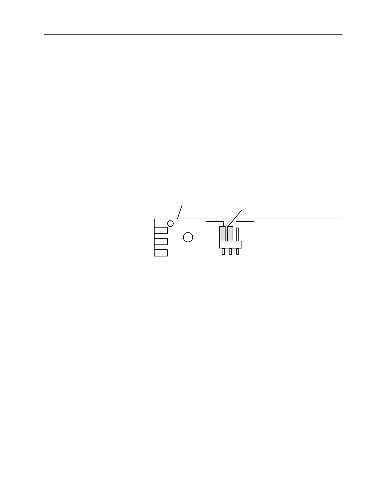
1. Locate the fault mode selection plug at the top edge of the
module circuit board.
Top edge of circuit board
Fault Mode Selection Plug
(shown in last state position)
RESET LS
10548I
2. Using your finger, slide the plug off the 2 posts.
3. Carefully position the plug on 2 of the 3 posts that correspond to
your requirement.
Keying Your I/O Chassis
Use the plastic keying bands, shipped with each I/O chassis, to key
the I/O slots to accept only this type of module.
The module circuit board is slotted in two places on the rear edge.
The position of the keying bands on the backplane connector must
correspond to these slots to allow insertion of the module. You can
key any connector in an I/O chassis to receive this module except for
the left-most connector reserved for adapter or processor modules.
Place keying bands between the following numbers labeled on the
backplane connector:
• Between 2 and 4
• Between 12 and 14
You can change the position of these keys if system redesign and
rewiring makes insertion of a different module necessary.
Publication
17715.27
Page 4

4
AC/DC (220V) Input Module Cat. No. 1771-IMD Series B
Installing the Input Module
To install the ac/dc input module in your 1771 I/O chassis, follow the
steps listed below.
ATTENTION: Remove power from the 1771 I/O
chassis backplane and field wiring arm before
!
removing or installing an I/O module.
• Failure to remove power from the backplane or wir-
ing arm could cause module damage, degradation of
performance, or injury.
• Failure to remove power from the backplane could
cause injury or equipment damage due to possible
unexpected operation.
1. Turn off power to the I/O chassis.
2. Place the module in the plastic tracks on the top and bottom of the
slot that guides the module into position.
3. Do not force the module into its backplane connector. Apply firm,
even pressure on the module to seat it properly.
4. Snap the chassis latch over the top of the module to secure its
position.
5. Connect the wiring arm to the module.
6. Make wiring connections to the field wiring arm as indicated in
“Connecting Wiring to the Input Module.”
Publication
17715.27
Page 5

AC/DC (220V) Input Module Cat. No. 1771-IMD Series B
5
Connecting Wiring to the Input Module
Connections to the input module are made to the 21 terminal field
wiring arm (cat. no. 1771-WH) shipped with the module. Attach the
wiring arm to the pivot bar on the bottom of the I/O chassis. The
wiring arm pivots upward and connects with the module so you can
install or remove the module without disconnecting the wires.
Connect one terminal of your 2-wire input devices to terminals 00
through 17.
Connection Diagram for the 1771-IMD Module
L1
Terminal A
Terminal B
Terminal C
Terminal D
Input 00
Input 01
Input 02
Input 03
Input 04
Input 05
Input 06
Input 07
Input 10
Input 11
Input 12
Input 13
Input 14
Input 15
Input 16
Input 17
Terminal E
A
B
C
D
00
01
02
03
04
05
06
07
10
11
12
13
14
15
16
17
E
ac/dc High
L2
ac/dc Low
(Actual wiring runs in this direction.)
10549I
Connect terminal E to the L2 (low) ac/dc return. Terminals A
through D are not used. Connect the L1 (high) ac/dc line to the other
terminal of your input devices. Use stranded 14 or 16 gauge wire to
minimize the voltage drop over long cable distances.
Publication
17715.27
Page 6

6
AC/DC (220V) Input Module Cat. No. 1771-IMD Series B
Important: You can use an AC (220V) Output Module (cat. no.
1771-OMD) to directly drive terminals on an AC/DC
(220V) Input Module (cat. no. 1771-IMD) as shown
below.
You can also use a 1771-OM Output module to drive an AC/DC
(220V) Input Module (cat. no. 1771-IMD) but you must connect a
10K ohm, 10W resistor between the output terminal and L2
(common) as shown below. Use the same ac power source to
power both modules to ensure proper phasing and prevent
module damage.
Driving
a 1771IMD Module with a 1771OMD Module
AC (220V)
Output Module
(Cat. No. 1771OMD)
L1
220V ac High
AC/DC (220V)
Input Module
(Cat. No. 1771IMD)
Driving an Input with an Output
AC (220V)
Output Module
(Cat. No. 1771OM)
AC/DC (220V)
Input Module
(Cat. No. 1771IMD)
220V ac High
L1
Publication
17715.27
L2
ac Low
10550I
10K ohm 10W
resistor
L2
ac Low
10551I
Page 7

AC/DC (220V) Input Module Cat. No. 1771-IMD Series B
7
Interpreting the Status Indicators
The front panel of your module contains one green, module active
LED, and 16 red status LED indicators. The 1771-IMD performs
diagnostics in a handshaking mode when first powered up. Upon
successful completion of the diagnostics, the green module active
indicator lights. It turns off if a fault occurs in the data paths or the
opto-isolators.
Module Active Indicator (green)
ACTIVE
00
10
01
11
02
12
03
13
04
14
05
15
06
16
07
17
00 to 17 Status Indicators (red)
10552I
If a module fault occurs, the module resets its inputs or sets them to
last state, depending on the fault mode selection. The module active
indicator must be on to properly interpret the red status indicators.
The red status indicators are provided for system logic side
indication of individual inputs. When a red indicator lights, voltage
is present on the terminal. The module transfers this information to
the backplane for the processor to read. See ”Troubleshooting” for a
description, probable cause, and recommended action to take for
common faults based on indicator responses.
Troubleshooting
Use this table to help you interpret the 1771-IMD status indicators
and to troubleshoot module and system faults.
Indicator Status (color) Description of Fault or System Status Action to Take
Module active ON (green) Normal Indication None
Module active ON (green) and
Input status ON (red)
Module active ON (green) and
Input status OFF
Module active OFF Module is not powered or fault in optoisolators
Check for voltage on terminal If none, replace module
Input devices not functioning properly or faulty
input circuitry on module
1. Check input devices
2. If input devices are OK, replace module
No voltage on terminal None
1. Check chassis power supply and module
and/or data paths; module resets inputs or goes to
last state
input power
2. If power supplies are OK, replace module
Module active OFF and
Input status ON (red) or OFF
Not valid unless module active indicator is on;
when active is off, indicators do not represent
processor status
1. Check chassis power supply and module
input power
2. If power supplies are OK, replace module
Publication
17715.27
Page 8

8
AC/DC (220V) Input Module Cat. No. 1771-IMD Series B
Specifications
Inputs per Module 16
Module Location 1771A1B, A2B, A3B, A3B1, A4B or later I/O chassis
Nominal Input Voltage 220V ac @ 50/60Hz; 220V dc
Nominal Input Current 10.4mA @ 220V ac 60Hz; 9.9mA @ 220V ac 50Hz
0.6mA @ 220V dc
Onstate Voltage Range 184V to 250V ac
166V to 230V dc
Minimum Onstate Current 8.7mA at 184V ac, 50Hz
0.43mA at 166V dc
Maximum Offstate Voltage 92V ac or dc
Maximum Offstate Current 3mA at 92V ac, 60Hz
0.25mA at 92V dc
Input Impedance 0.15uF (21.2K at 50Hz) in parallel with 370K; in series with 1K ohm
Peak Inrush Current VPS/1K ohm, where VPS = customer supply peak voltage
Input Signal Delay Off to on:
On to off:
15+8ms for ac or dc
56ms for ac or dc
172+
Power Dissipation 5.8 Watts (max.), 1.3 Watts (min.)
Thermal Dissipation 19.8 BTU/hr (max.), 4.5 BTU/hr (min.)
Backplane Current 250mA @ 5V dc
Isolation Voltage Isolation meets or exceeds UL Standard 508, and CSA Standard
C22.2 No. 142.
Environmental Conditions
Operational Temperature
Storage Temperature
Relative Humidity
Conductors Wire Size
Category
0o to 60oC (32o to 140oF)
o
40
to 85oC (40o to 185oF)
5 to 95% (without condensation)
14 gauge stranded maximum
3/64 inch insulation maximum
1
1
Keying Between 2 and 4
Between 12 and 14
Field Wiring Arm Catalog Number 1771WH
Wiring Arm Screw Torque 79 inchpounds
Agency Certification
(when product or packaging is
marked)
• CSA certified
• CSA Class I, Division 2, Groups A, B, C, D certified
• UL listed
• CE marked for all applicable directives
1
Refer
to publication 17704.1, Programmable Controller Wiring and Grounding Guidelines.
AllenBradley, a Rockwell Automation Business, has been helping its customers improve
productivity and quality for more than 90 years. We design, manufacture and support a broad
range of automation products worldwide. They include logic processors, power and motion
control devices, operator interfaces, sensors and a variety of software. Rockwell is one of the
world's leading technology companies.
Worldwide representation.
Argentina •
Denmark • Ecuador
Ireland
Philippines •
Sweden
AllenBradley Headquarters, 1201 South Second Street, Milwaukee, WI 53204 USA, Tel: (1) 414 3822000 Fax: (1) 414 3824444
Publication
Australia • Austria • Bahrain
• Israel • Italy • Jamaica •
• Switzerland • T
17715.27 - November 1995
Publication
• Egypt • El Salvador • Finland • France •
Poland • Portugal • Puerto Rico • Qatar • Romania • Russia-CIS • Saudi Arabia • Singapore
aiwan
17715.27
• Belgium • Brazil •
Japan • Jordan • Korea • Kuwait • Lebanon
• Thailand • T
urkey • United Arab Emirates • United Kingdom • United States • Uruguay
Bulgaria • Canada
Germany • Greece • Guatemala • Honduras • Hong Kong • Hungary
• Chile •
China, PRC • Colombia
• Malaysia • Mexico •
• Costa Rica •
Netherlands
• New Zealand •
• Slovakia • Slovenia •
Croatia • Cyprus
Norway
South Africa, Republic
• V
enezuela
Copyright
• Iceland •
• Yugoslavia
• Czech Republic •
India • Indonesia
• Pakistan •
1995 AllenBradley Company
•
Peru
•
• Spain •
PN955122-71
, Inc. Printed in USA
 Loading...