

Page 1

Installation Instructions
TTL Input Module
Cat. No. 1771–IGD
To The Installer
Important User Information
Use this document as a guide when installing the catalog number
1771-IGD TTL input module.
For information on: See page
Important User Information 1
Preinstallation Considerations 3
Calculate Power Requirements 4
Initial Handling 4
Set the Logic Level 5
Key the Backplane Connector 6
Install the Module and Field Wiring Arm 7
Connect Wiring to the Output Module 8
Replacing the Fuse 11
For this reference information See page
Intepreting the Status Indicators 11
Specifications 11
Because of the variety of uses for the products described in this
publication, those responsible for the application and use of these
products must satisfy themselves that all necessary steps have been
taken to assure that each application and use meets all performance
and safety requirements, including any applicable laws, regulations,
codes and standards. In no event will Rockwell Automation be
responsible or liable for indirect or consequential damage resulting
from the use or application of these products.
Any illustrations, charts, sample programs, and layout examples
shown in this publication are intended solely for purposes of
example. Since there are many variables and requirements associated
with any particular installation, Rockwell Automation does not
assume responsibility or liability (to include intellectual property
liability) for actual use based upon the examples shown in this
publication.
Publication 1771ĆIN022B-EN-P - September 2002
Page 2
TTL Input Module2
T
Allen–Bradley publication SGI–1.1, Safety Guidelines for
Application, Installation, and Maintenance of Solid–State Control
(available from your local Rockwell Automation office), describes
some important differences between solid–state equipment and
electromechanical devices that should be taken into consideration
when applying products such as those described in this publication.
Reproduction of the contents of this copyrighted publication, in
whole or part, without written permission of Rockwell Automation,
is prohibited.
Throughout this publication, notes may be used to make you aware
of safety considerations. The following annotations and their
accompanying statements help you to identify a potential hazard,
avoid a potential hazard, and recognize the consequences of a
potential hazard.
WARNING
!
ATTENTION
!
IMPORTAN
Identifies information about practices or
circumstances that can cause an explosion in a
hazardous environment, which may lead to
personal injury or death, property damage, or
economic loss.
Identifies information about practices or
circumstances that may lead to personal injury or
death, property damage, or economic loss.
Identifies information that is critical for
successful application and understanding of the
product.
Publication 1771ĆIN022B-EN-P - September 2002
Page 3

TTL Input Module 3
ATTENTION
!
Environment and Enclosure
This equipment is intended for use in a Pollution
Degree 2 industrial environment, in overvoltage
Category II applications (as defined in IEC
publication 60664–1), at altitudes up to 2000
meters without derating.
This equipment is considered Group 1, Class A
industrial equipment according to IEC/CISPR
Publication 11. Without appropriate precautions,
there may be potential difficulties ensuring
electromagnetic compatibility in other
environments due to conducted as well as radiated
disturbance.
This equipment is supplied as “open type”
equipment. It must be mounted within an
enclosure that is suitably designed for those
specific environmental conditions that will be
present, and appropriately designed to prevent
personal injury resulting from accessibility to live
parts. The interior of the enclosure must be
accessible only by the use of a tool. Subsequent
sections of this publication may contain additional
information regarding specific enclosure type
ratings that are required to comply with certain
product safety certifications.
PreĆinstallation
Considerations
See NEMA Standards publication 250 and IEC
publication 60529, as applicable, for explanations
of the degrees of protection provided by different
types of enclosures. Also, see the appropriate
sections in this publication, as well as the
Allen–Bradley publication 1770–4.1, (“Industrial
Automation Wiring and Grounding Guidelines”),
for additional installation requirements pertaining
to this equipment.
You can use this module in a Series A or B 1771-A1B, -A2B, -A3B,
-A3B1, and -A4B chassis. The module is also compatible in a
1771-AM1 or -AM2 I/O chassis.
You can use any TTL device that meets the output logic level
specification of -0.2V dc to +0.8V dc (low), and 2.0V dc to 5.25V dc
(high).
This module contains input filtering to limit the effects of voltage
transients caused by contact bounce and/or radiated electrical noise.
The delay due to filtering is less than 1ms.
Publication 1771ĆIN022B-EN-P - September 2002
Page 4

TTL Input Module4
For maximum noise immunity, the output of the TTL device should
have a pull-up resistor of 1k ohm (typical). Add an external pull-up
resistor to the output terminals of the device, if necessary. If you add
a pull-up resistor, be sure the TTL device maintains the low state
requirement of -0.2V dc to +0.8V dc with the increased load.
Calculate Power
Requirements
Initial Handling
The TTL module requires power from two sources: the I/O chassis
backplane, and a +5V dc Class 2 power supply that you provide for
transmission of TTL signals.
Backplane
The TTL module receives its power through the 1771 I/O chassis
backplane from the chassis power supply. The module requires
130mA from the output of this supply. Add this to the requirements
of all other modules in the I/O chassis to prevent overloading the
chassis backplane and/or backplane power supply.
Customer Supply
You must provide a separate +5(+
for the TTL inputs of the module and for your TTL output devices.
Your module requires 380mA from the output of your supply. Ripple
should not exceed 50mV peak to peak.
The TTL input module is shipped in static-safe packaging to guard
against electrostatic discharge damage. Observe the following
precautions when handling the module.
ATTENTION
!
Preventing Electrostatic Discharge
This equipment is sensitive to electrostatic
discharge, which can cause internal damage and
affect normal operation. Follow these guidelines
when you handle this equipment:
• Touch a grounded object to discharge potential
static.
0.25)V dc Class 2 power supply
• Wear an approved grounding wriststrap.
• Do not touch connectors or pins on component
boards.
• Do not touch circuit components inside the
equipment.
• If available, use a static–safe workstation.
• When not in use, keep modules in appropriate
static–safe packaging.
Publication 1771ĆIN022B-EN-P - September 2002
Page 5
TTL Input Module 5
4
Setting the Logic Level
Your module is preset to the positive-logic level. Use the following
table to choose between the two logic levels:
If you choose: Then: Jumper Position
HIGH = TRUE logic (positive) 2.0 to 5.25V dc corresponds to logic ``1" (on) Toward rear of module
LOW = TRUE logic (negative) -0.2 to 0.8V dc corresponds to logic ``1" (on) Toward front of module
Note: Selecting positive logic automatically enables the HIGH (positive logic) indicator.
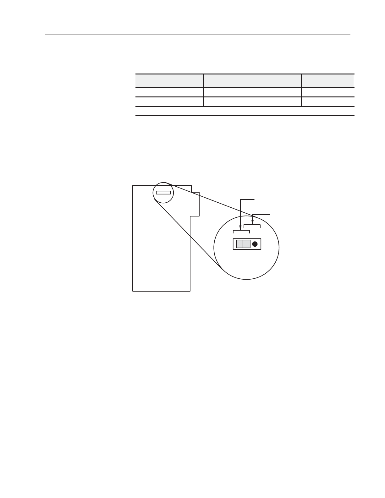
You select high-true or low-true using the jumper accessible through
a slot at the top of the module.
1. Locate the jumper in the slot at the top edge of the module.
2. Use tweezers to position the jumper as required for your
application.
TTL Logic Level Selection Jumper Assembly
When on rear 2 pins, positive logic
selected (high = true).
When on front 2 pins, negative logic
selected (low = true).
TTL Input Module
104
Publication 1771ĆIN022B-EN-P - September 2002
Page 6

TTL Input Module6
Key the Backplane
ATTENTION
Connector
Place your module in any slot in the chassis
except the leftmost slot, which is reserved for
processors or adapters.
ATTENTION
!
Observe the following precautions
when inserting or removing keys:
• insert or remove keys with your
fingers
• make sure that key placement is
correct
Incorrect keying or the use of a tool
can result in damage to the
backplane connector and possible
system faults.
A module inserted into a wrong slot could be
damaged by improper voltages connected through
the wiring arm. Use keying bands to prevent
damage to the module.
!
Position the keying bands in the backplane connectors to correspond to
the key slots on the module.
I/O chassis
Place the keying bands:
- between 16 and 18
- between 24 and 26
Upper Connector
You can change the position of these bands if
subsequent system design and rewiring makes
insertion of a different type of module necessary.
11022ĆI
Publication 1771ĆIN022B-EN-P - September 2002
Page 7

TTL Input Module 7
Install the Module and Field
Wiring Arm
1771ĆA1B, ĆA2B, ĆA3B, ĆA3B1, ĆA4B I/O chassis
locking tab
card guides
Snap the chassis latch over
the top of the module to secure it.
ATTENTION
!
module
Remove power from the 1771 I/O chassis
backplane and field wiring arm before removing
or installing an I/O module.
• Failure to remove power from the backplane or
wiring arm could cause module damage, degradation of performance, or injury.
• Failure to remove power from the backplane
could cause injury or equipment damage due to
possible unexpected operation.
1771ĆA1B, ĆA2B, ĆA3B1, ĆA4B Series B I/O chassis
locking bar pin
Swing the chassis locking bar down into place to secure
the modules. Make sure the locking pins engage.
locking bar
card guides
module
19809
Attach the wiring arm (1771ĆWH) to the horizontal
bar at the bottom of the I/O chassis.
The wiring arm pivots upward and connects with
the module so you can install or remove the
module without disconnecting the wires.
The 1771–IGD module is a modular component of the 1771 I/O
system requiring a properly installed system chassis. Refer to
publication 1771–IN075 for detailed information on acceptable
chassis, proper installation and grounding requirements. Limit the
maximum adjacent slot power dissipation to 10W maximum.
horizontal bar
remove
install
wiring arm
1771ĆWH
17643
Publication 1771ĆIN022B-EN-P - September 2002
Page 8

TTL Input Module8
Connect Wiring to the
Input Module
ATTENTION
Remove power from the 1771 I/O chassis
backplane and field wiring arm before removing
or installing an I/O module.
• Failure to remove power from the backplane or
!
wiring arm could cause module damage,
degradation of performance, or injury.
• Failure to remove power from the backplane
could cause injury or equipment damage due to
possible unexpected operation.
Connect wiring to the input module using the field wiring arm (cat.
no. 1771-WH) shipped with the module (shown in the connection
diagram below). Make your connections as follows:
1. Attach the field wiring arm to the pivot bar on the bottom of the
I/O chassis.
2. Pivot the wiring arm upward and push it into the module until the
wiring arm clicks into position. The field wiring arm is designed
to let you install and remove the module without disconnecting
the wires.
ATTENTION
Do not apply ac or reverse dc voltage to
module terminals. Circuitry at the input of
module may be damaged.
Remove a length of cable
jacket from the Belden 8761 cable.
Belden 8761 Cable
!
3. Separate the shielded cables from wiring that radiates electrical
noise. Refer to category 2, low power dc I/O lines, in publication
1770-4.1, ‘‘Programmable Controller Wiring and Grounding
Guidelines”.
4. Prepare the cable for grounding by doing the following:
Pull the foil shield and bare
drain wire from the insulated wires.
Bare drain
wire
Insulated
wires
Foil
shield
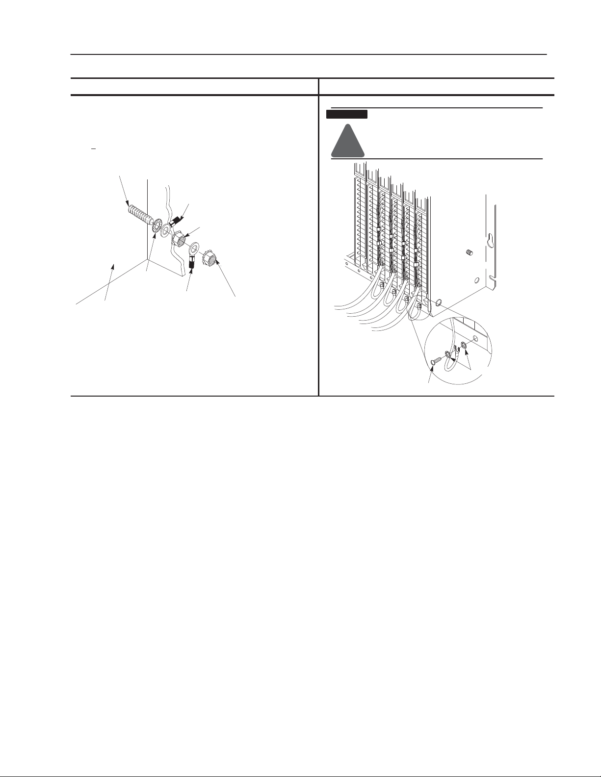
5. Ground the single strand (at the ground lug end) to the grounding
stud on the I/O chassis or by using single-point grounding.
Twist the foil shield and drain
wire together to form a single strand.
Attach a ground lug.
20104
Publication 1771ĆIN022B-EN-P - September 2002
Page 9
Chassis Ground SingleĆpoint Grounding
m
TTL Input Module 9
When you connect grounding conductors to the I/O chassis grounding
stud, place a star washer under the first lug, then place a nut with captive
lock washer on top of each ground lug. Torque the nut with captive washer
to 18(+
3) pound-inches.
grounding stud
ground lug
nut with captive washer
star washer
ground lug
I/O chassis side plate
1
Use the cup washer if crimpĆon lugs are not used.
1
nut with captive washer
19480
ATTENTION
!
!
Use singleĆpoint grounding for extendedĆlocal I/O syste
The systems must be grounded properly for proper
performance.
externalĆtooth washers
#10 threadĆforming screw
19923
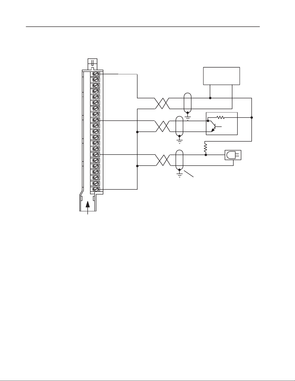
6. You must connect both ends of the insulated signal return wire in
each transmission cable as follows:
• connect one end to the dc common terminal of your +5V dc
Class 2 power supply
• connect the other end to the dc common terminal of the field
wiring arm
Publication 1771ĆIN022B-EN-P - September 2002
Page 10
TTL Input Module10
Field Wiring Arm
Cat. No. 1771ĆWH
(See applicable codes and laws.)
+5V dc
+5V dc
+5V dc
+5V dc
Input 00
Input 01
Input 02
Input 03
Input 04
Input 05
Input 06
Input 07
Input 10
Input 11
Input 12
Input 13
Input 14
Input 15
Input 16
Input 17
dc common
A
B
C
D
00
01
02
03
04
05
06
07
10
11
12
13
14
15
16
17
E
(Actual wiring runs in this direction.)
Do not exceed the specified isolation voltage when using multiple power sources.
1
Customer Class 2
Power Supply
+5V dc
+
3
3
-
2
2
Ground cable shield at the chassis
grounding stud or by using singleĆpoint
grounding
1
You can make this connection to terminal A, B, C or D.
2
TTL Devices must have openĆcollector outputs.
3
Internal or external pullĆup resistor (1K ohm typical).
10450ĆI
Publication 1771ĆIN022B-EN-P - September 2002
7. Connect TTL output devices using Belden 8761 shielded cable as
shown in the connection diagram. Do not exceed 50 cable feet for
any output device. Connect the insulated wires to their respective
terminals on the field wiring arm.
Driving Inputs with Outputs
Input terminals of the TTL input module (cat. no. 1771-IGD) may be
directly driven by the outputs of a TTL output module (cat. no.
1771-OGD). Connect the cable shield between modules at one end
only.
Page 11

TTL Input Module 11
Interpreting the Status
Indicators
Module Active
ACTIVE
10
00
11
01
12
02
13
03
04
05
06
07
HIGH
14
15
16
17
00 to 17 Status
Positive Logic
Replacing the Fuse
Indicator
(green)
Indicators (red)
Indicator
(green)
The front panel of your module contains 18 status indicators. The
green top indicator is labeled ‘‘ACTIVE.” This indicator is on when
the fuse is good. The green bottom indicator, when on, indicates you
selected high-true logic. When off, it indicates you selected low-true
logic.
Each of the 16 red status indicators light when their corresponding
input terminal senses TTL voltages in the true state.
10451ĆI
To replace a blown fuse, proceed as follows:
ATTENTION
Remove power from the 1771 I/O chassis
backplane and field wiring arm before removing
or installing an I/O module.
• Failure to remove power from the backplane or
!
wiring arm could cause module damage, degradation of performance, or injury.
• Failure to remove power from the backplane
could cause injury or equipment damage due to
possible unexpected operation.
Specifications
1. Turn off power to the chassis.
2. Remove the module from the I/O chassis.
3. Remove the blown fuse from the fuse holder (accessible through
the slot in the side cover), and replace with a 0.5A, 250V normal
blow fuse.
4. Reinsert module into the I/O chassis.
5. Turn on power to the chassis.
Inputs per Module 16
Module Location 1771ĆA1B thruĆA4B or later I/O chassis,
Input Voltage Rating HIGH = TRUE
LOW = TRUE
Customer Current Sink
Requirements
Customer Supply Voltage 5.0V dc (+0.25V) Class 2
Specifications continued on next page.
1771ĆAM1, and ĆAM2 I/O chassis.
ON: 2.0 to 5.25V dc
OFF: -0.2 to +0.8V dc
ON: -0.2 to +0.8V dc
OFF: 2.0 to 5.25V dc
7mA maximum (source per input)
0.8mA maximum (sink per input)
50mV peakĆtoĆpeak ripple max.
Publication 1771ĆIN022B-EN-P - September 2002
Page 12

TTL Input Module12
Customer Supply Current per
380mA max.
Module
Input Signal Delay Less than 1ms
Power Dissipation 2.7 Watts (max.); 0.4 Watts (min.)
Thermal Dissipation 9.2 BTU/hr (max.); 1.4 BTU/hr (min.)
Backplane Voltage/Current 5V dc, 130mA max.
Isolation Voltage Tested to 600V dc for 1s
Environmental Conditions
Operating
Temperature
IEC 60068-2-1 (Test Ad, Operating Cold)
IEC 60068-2-2 (Test Bd, Operating Dry Heat)
IEC 60068-2-14 (Test Nb, Operating Thermal Shock)
32to131°F(0
o
to 60oC)
Storage Temperature IEC 60068-2-1 (Test Ab, Unpackaged, Nonoperating Cold)
IEC 60068-2-2 (Test Bb, Unpackaged, Nonoperating Dry Heat)
IEC 60068-2-14 (Test Na, Unpackaged, Nonoperating Thermal Shock)
-40 to 185°F (-40 to 85
o
C)
Relative Humidity IEC 60068-2-30 (Test Db, Unpackaged, Nonoperating Damp Heat)
5 to 95%, noncondensing
Enclosure Type Rating None (open-style)
Keying Between 16 and 18
Between 24 and 26
Fuse 0.5A 250V normal blow
Conductors Wire Size
14 AWG (2.5mm2) stranded copper rated at 60oC or greater
3/64 inch (1.2mm) insulation (max)
Cable
Category
Shielded (Belden 8761)
1
2
Field Wiring Arm Catalog Number 1771ĆWH
Wiring Arm Screw Torque 9 pound-inches (1.0Nm)
Certifications
(when product is marked)
UL UL Listed Industrial Control Equipment
CSA CSA Certified Process Control Equipment
CE2European Union 89/336/EEC EMC Directive,
compliant with:
EN 50082-2, Industrial Immunity
EN 61236, Meas./Control/Lab., Industrial Requirements
EN 61000-6-2, Industrial Immunity
EN 61000-6-4, Industrial Emissions
2
Australian Radiocommunications Act, compliant with:
C-Tick
AS/NZS 2064, Industrial Emissions
1
You use this conductor category information for planning conductor routing as described in publication 1770Ć4.1, Industrial
Automation Wiring and Grounding Guidelines.
2
See the Product Certification link at www.ab.com for Declarations of Conformity, Certificates and other certification details
Publication 1771ĆIN022B-EN-P - September 2002
Supersedes Publication 1771Ć5.22 - October 1995
Publication 1771ĆIN022B-EN-P - September 2002
Copyright 2002 Rockwell Automation Inc. Printed in USA
PN957689-09
 Loading...