

Page 1
Publication 1771-IN001A–EN–P – May 2000
ac (120V) Isolated Input
Module
Cat. No. 1771-ID16GM
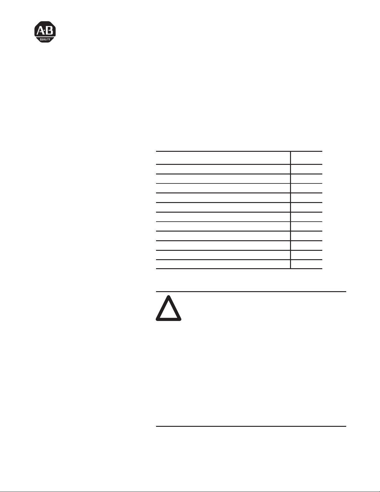
Use this document as a guide when installing the ac Isolated Input
module.
For information on: See Page:
General Information 2
Understand compliance to European Union directives 2
Calculate power requirements 2
Initial handling 3
Set the filter time 3
Key the backplane connector 5
Install the module and field wiring arm 5
Connect the wiring to the module 6
Interpret the status indicators 8
CSA Hazardous Location Approval 10
Specifications 11
!
ATTENTION: The 1771-ID16GM isolated input
module is designed specifically for General Motors
Corporation use only. This module has specific input
current requirements as outlined in the specifications at
the end of this installation instruction.
For proper circuit operation:
• maximum input voltage is limited to 120V ac
• all inductive or solenoid input loads must provide
external surge suppression
In addition, this module has been qualified for Bulletin
700P style 120V relay circuits only.
Use this module in a series B or later I/O chassis. The
1771-ID16GM is not compatible with the 1771-AL
local I/O adapter.
Installation Instructions
Contents
Page 2

ac (120V) Isolated Input Module2
Publication 1771-IN001A–EN–P – May 2000
This module contains customer-selectable input filtering to limit the
effects of voltage transients caused by contact bounce and/or radiated
electrical noise. The delay due to filtering is 9.0 or 18.0ms for
turning ac inputs on to off, and 1.0ms for turning ac inputs off to on.
The filter time is factory set to 9.0ms.
If this product has the CE mark it is approved for installation within
the European Union and EEA regions. It has been designed and
tested to meet the following directives.
EMC Directive
This product is tested to meet Council Directive 89/336/EEC
Electromagnetic Compatibility (EMC) and the following standards,
in whole or in part, documented in a technical construction file:
• EN 50081-2EMC – Generic Emission Standard,
Part 2 – Industrial Environment
• EN 50082-2EMC – Generic Immunity Standard,
Part 2 – Industrial Environment
This product is intended for use in an industrial environment.
Low Voltage Directive
This product is tested to meet Council Directive 73/23/EEC
Low Voltage, by applying the safety requirements of EN 61131–2
Programmable Controllers, Part 2 – Equipment Requirements and
Tests.
For specific information required by EN 61131-2, see the appropriate
sections in this publication, as well as “Industrial Automation Wiring
and Grounding Guidelines,” Allen-Bradley publication 1770-4.1
Open style devices must be provided with environmental and safety
protection by proper mounting in enclosures designed for specific
application conditions. See NEMA Standards publication 250 and
IEC publication 529, as applicable, for explanations of the degrees of
protection provided by different types of enclosure.
Your module receives its power through the 1771 I/O chassis
backplane from the chassis power supply. The module requires
75mA from the output of this supply. Add this to the requirements of
all other modules in the I/O chassis to prevent overloading the
chassis backplane and/or backplane power supply.
General Information
Understand Compliance to
European Union Directives
Calculate Power
Requirements
Page 3

ac (120V) Isolated Input Module 3
Publication 1771-IN001A–EN–P – May 2000
The isolated input module is shipped in a static-shielded bag to guard
against electrostatic discharge damage. Observe the following
precautions when handling the module.
Electrostatic Discharge Damage
!
ATTENTION: Under some conditions, electrostatic
discharge can degrade performance or damage the
module. Observe the following precautions to guard
against electrostatic damage.
• Wear an approved wrist strap grounding device, or touch a
grounded object to discharge yourself before handling the
module.
• Do not touch the backplane connector or connector pins.
• If you configure or replace internal components, do not touch
other circuit components inside the module. If available, use a
static-free work station.
• When not in use, keep the module in a static-shielded bag.
The input module has 2 customer-selectable input filter time
jumpers. Jumper JPR 1 sets the input filter time for inputs 00 through
07, and jumper JPR 2 sets the input filter time for inputs 10 through
17. These filter times apply when the input is cycling from ON to
OFF. The OFF to ON filter time is fixed at 0.57ms. Refer to the
figure on page 4 for filter times and jumper settings.
Important: Half cycle dropout protection is dependent upon the
position of the jumpers. With the jumpers at the 9.0ms
position (Fast), half cycle protection may not be
guaranteed. If half cycle dropout protection is required,
position the jumpers in the 18.0ms position (Norm).
Maximum and minimum filter times are shown in
Table A.
Initial Handling
Set the Filter Time
Page 4
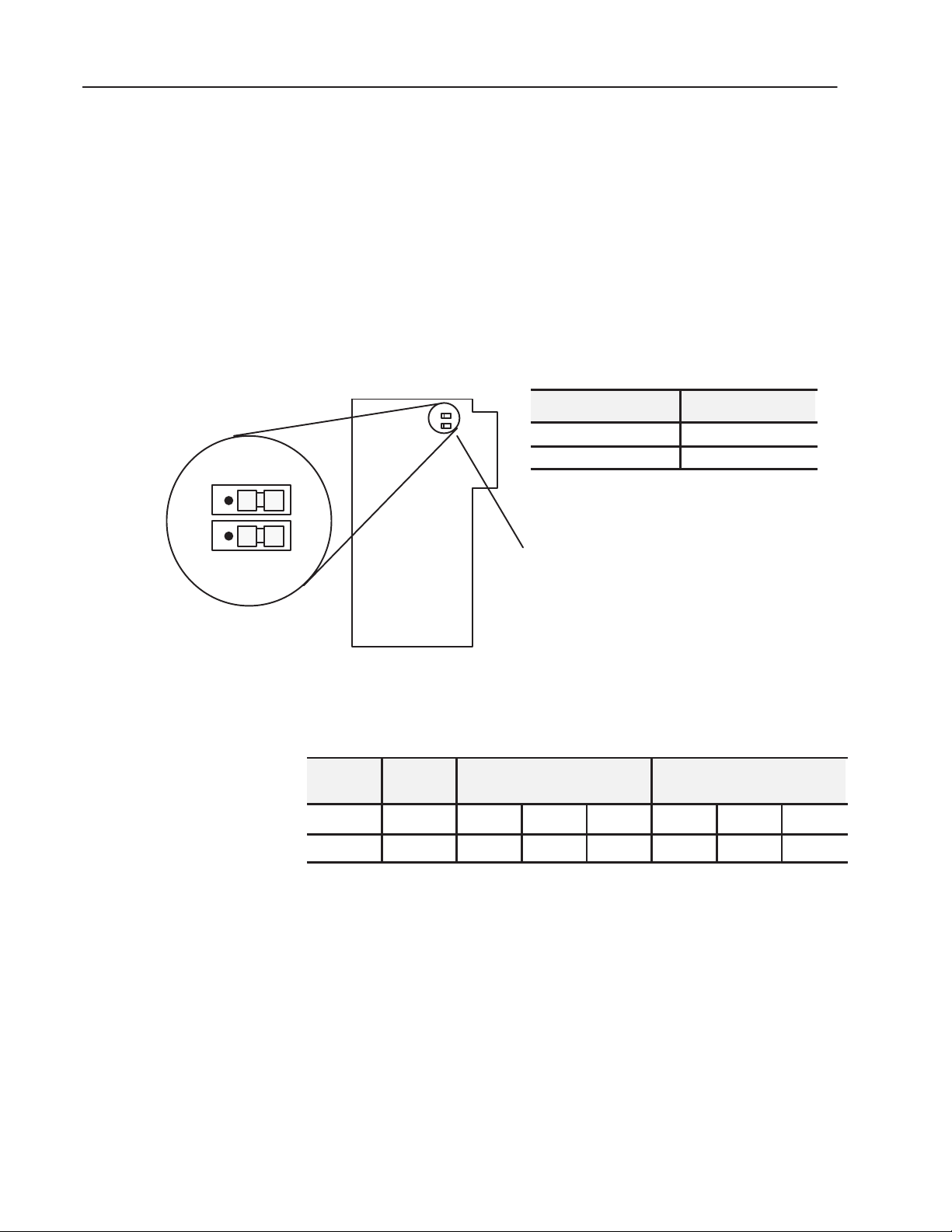
Filter Time Jumpers
E1 = Jumper for inputs 00 through 07
E2 = Jumper for inputs 10 through 17
NORM
NORM
FAST
FAST
CH0–7
CH10–17
E1
E2
10557-I
ac (120V) Isolated Input Module4
Publication 1771-IN001A–EN–P – May 2000
To set the filtering time, proceed as follows:
1. Remove the side covers from the module circuit board by
removing the four screws securing the covers to the module and
remove the circuit board.
2. Position the jumpers as required to provide the filter time you
require (see below). Use your fingers to pull the jumper up and
position over the 2 pins corresponding to your selection (Fast or
Norm).
Setting the Filter Time Jumpers
Jumper Position Time Constant (ms)
Fast (factory default) 9.0 (ac)
Norm 18.0 (ac)
3. Reinstall the covers on the module circuit board and secure with 4
screws.
Table A
Minimum and Maximum Filter Times
Input
Voltage
Filter Time
(msec)
Off to On (ms)
Minimum Maximum Typical
On to Off (ms)
Minimum Maximum Typical
ac 9.0 0.5 7.0 2.0 7.0 33 20
ac 18.0 0.5 8.1 2.0 14.0 42 29
Page 5

ac (120V) Isolated Input Module 5
Publication 1771-IN001A–EN–P – May 2000
Key
the Backplane Connect
or
Place your module in any slot in the chassis
except the leftmost slot which is reserved for
processors or adapters.
ATTENTION: Observe the following
precautions when inserting or removing
keys:
• insert or remove keys with your fingers
• make sure that key placement is correct
Incorrect keying or the use of a tool can
result in damage to the backplane
connector and possible system faults.
!
Position the keying bands in the backplane connectors to correspond to
the key slots on the module.
Place the keying bands:
between 22 and 24
between 26 and 28
You can change the position of these bands if
subsequent system design and rewiring makes
insertion of a different type of module necessary.
Upper Connector
11022-I
I/O chassis
!
ATTENTION: Remove power from the 1771 I/O
chassis backplane and field wiring arm before
removing or installing an I/O module.
• Failure to remove power from the backplane or wir-
ing arm could cause module damage, degradation of
performance, or injury.
• Failure to remove power from the backplane could
cause injury or equipment damage due to possible
unexpected operation.
Swing the chassis locking bar down into place to secure
the modules. Make sure the locking pins engage.
1771-A1B, -A2B, -A3B, -A3B1, -A4B I/O chassis
1771-A1B, -A2B, -A3B1, -A4B Series B I/O chassis
locking tab
card guides
Module
Module
19809
card guides
locking bar
locking bar pin
Snap the chassis latch over
the top of the module to secure it.
1
Install the Module and Field
Wiring Arm
Page 6

ac (120V) Isolated Input Module6
Publication 1771-IN001A–EN–P – May 2000
17643
wiring arm
install
remove
horizontal bar
Attach the wiring arm (1771-WN) to the horizontal
bar at the bottom of the I/O chassis.
The wiring arm pivots upward and connects with
the module so you can install or remove the
module without disconnecting the wires.
1771-WN
2
Connections to the input module are made to the 40 terminal field
wiring arm (cat. no. 1771-WN) shipped with the module. Attach the
wiring arm to the pivot bar on the bottom of the I/O chassis. The
wiring arm pivots upward and connects with the module so you can
install or remove the module without disconnecting the wires.
1. Make certain all power is removed from the module before
making wiring connections.
2. Swing the wiring arm up into position on the front of the module.
The locking tab on the module will secure it into place.
3. Make your connections to the field wiring arm as shown in the
following figure. (Use the label on the front of the wiring arm to
identify your wiring.)
Note: A shorting bar may be used to connect the commons if
channel-to-channel isolation is not required.
!
ATTENTION: The field wiring arm terminal
identification number is not the same as the number of
the bit associated with that input.
Connect the Wiring to the
Module
Page 7

ac (120V) Isolated Input Module 7
Publication 1771-IN001A–EN–P – May 2000
Figure 1
Connection Diagram for the 1771-ID16GM ac (120V) Isolated Input
Module
Input 0
Input 1
Input 2
Input 3
Input 4
Input 5
Input 6
Input 7
Input 10
Input 11
Input 12
Input 13
Input 14
Input 15
Input 16
Input 17
L2
ac High
ac Low
L2 - 0
L2 - 1
L2 - 2
L2 - 3
L2 - 4
L2 - 5
L2 - 6
L2 - 7
L2 - 10
L2 - 11
L2 - 12
L2 - 13
L2 - 14
L2 - 15
L2 - 16
L2 - 17
Not Used
Not used
Not used
Not used
Not used
Not used
Not used
Not used
120V ac
Supply
L2
L1
2
4
6
8
10
12
14
16
18
20
22
24
26
28
30
32
34
36
38
40
(Actual wiring runs in this direction.)
ac Low
ac Input
!
ATTENTION: Maintain isolation between phases to
prevent module damage.
!
ATTENTION: Do not use any 1771 ac output
modules to drive the 1771-ID16GM input module.
Page 8

ac (120V) Isolated Input Module8
Publication 1771-IN001A–EN–P – May 2000
The module has 17 indicators (below), consisting of 16 input status
indicators and an active indicator. The 16 status indicators will light
when the field load has been applied to the field wiring arm of the
module.
00
01
02
03
04
05
06
07
10
11
12
13
14
15
16
17
Input State Indicators
(red)
ACTIVE
ACTIVE Indicator
(green)
10560-I
The active indicator will light when the module has successfully
started up and has initialized.
Interpreting the Status
Indicators
Page 9

ac (120V) Isolated Input Module 9
Publication 1771-IN001A–EN–P – May 2000
Page 10

ac (120V) Isolated Input Module10
Publication 1771-IN001A–EN–P – May 2000
CSA Hazardous Location Approval Approbation d’utilisation dans des emplacements dangereux
par la CSA
CSA® certifies products for general use as well as for use in hazardous locations.
Actual CSA certification is indicated by the product label as shown below, and
not by statements in any user documentation.
La CSA® certifie les produits d’utilisation générale aussi bien que ceux qui
s’utilisent dans des emplacements dangereux. La certification CSA en vigueur
est indiquée par l’étiquette du produit et non par des affirmations dans la
documentation à l’usage des utilisateurs.
Example of the CSA certification product label
I
Exemple d’étiquette de certification d’un produit par la CSA
I
To comply with CSA certification for use in hazardous locations, the following
information becomes a part of the product literature for CSA-certified Allen-Bradley
industrial control products.
• This equipment is suitable for use in Class I, Division 2, Groups A, B, C, D, or
non-hazardous locations only.
• The products having the appropriate CSA markings (that is, Class I Division 2,
Groups A, B, C, D), are certified for use in other equipment where the suitability
of combination (that is, application or use) is determined by the CSA or the local
inspection office having jurisdiction.
Pour satisfaire à la certification de la CSA dans des endroits dangereux, les
informations suivantes font partie intégrante de la documentation des produits
industriels de contrôle Allen-Bradley certifiés par la CSA.
• Cet équipement convient à l’utilisation dans des emplacements de Classe I,
Division 2, Groupes A, B, C, D, ou ne convient qu’à l’utilisation dans des
endroits non dangereux.
• Les produits portant le marquage approprié de la CSA (c’est à dire, Classe I,
Division 2, Groupes A, B, C, D) sont certifiés à l’utilisation pour d’autres
équipements où la convenance de combinaison (application ou utilisation) est
déterminée par la CSA ou le bureau local d’inspection qualifié.
Important: Due to the modular nature of a PLC® control system, the product with
the highest temperature rating determines the overall temperature code rating of a
PLC control system in a Class I, Division 2 location. The temperature code rating is
marked on the product label as shown.
Important: Par suite de la nature modulaire du système de contrôle PLC®, le
produit ayant le taux le plus élevé de température détermine le taux d’ensemble
du code de température du système de contrôle d’un PLC dans un emplacement
de Classe I, Division 2. Le taux du code de température est indiqué sur l’étiquette
du produit.
Temperature coderating
Look for temperature code
rating here
I
Le taux du code de
température est indiqué ici
Taux du code de température
I
The following warnings apply to products having CSA certification for use in
hazardous locations.
Les avertissements suivants s’appliquent aux produits ayant la certification CSA
pour leur utilisation dans des emplacements dangereux.
!
WARNING: Explosion hazard —
• Substitution of components may impair suitability for Class I,
Division 2.
• Do not replace components unless power has been switched
off or the area is known to be non-hazardous.
• Do not disconnect equipment unless power has been switched
off or the area is known to be non-hazardous.
• Do not disconnect connectors unless power has been switched
off or the area is known to be non-hazardous. Secure any
user-supplied connectors that mate to external circuits on an
Allen-Bradley product using screws, sliding latches, threaded
connectors, or other means such that any connection can
withstand a 15 Newton (3.4 lb.) separating force applied for a
minimum of one minute.
!
AVERTISSEMENT: Risque d’explosion —
• La substitution de composants peut rendre ce matériel
inacceptable pour lesemplacements de Classe I, Division 2.
• Couper le courant ou s’assurer quel’emplacement est désigné
non dangereux avant de remplacer lescomposants.
• Avant de débrancher l’équipement, couper le courant ou
s’assurer que l’emplacement est désigné non dangereux.
• Avant de débrancher les connecteurs, couper le courant ou
s’assurer que l’emplacement est reconnu non dangereux.
Attacher tous connecteurs fournis par l’utilisateur et reliés aux
circuits externes d’un appareil Allen-Bradley à l ’aide de vis,
loquets coulissants, connecteurs filetés ou autres moyens
permettant aux connexions de résister à une force de
séparation de 15 newtons (3,4 lb. - 1,5 kg) appliquée pendant
au moins une minute.
CSA logo is a registered trademark of the Canadian Standards Association
PLC is a registered trademark of Allen-Bradley Company, Inc.
Le sigle CSA est la marque déposée de l’Association des Standards pour le Canada.
PLC est une marque déposée de Allen-Bradley Company, Inc.
Page 11

Specifications
ac (120V) Isolated Input Module 11
Publication 1771-IN001A–EN–P – May 2000
Inputs per Module 16
Module Location 1771-A1B thru -A4B or later I/O chassis; 1771-AM1, -AM2 chassis
Input Voltage Range 105–120V ac, 47-63Hz
Nominal Input Voltage 120V ac
Nominal Input Current 2.5mA ac
On State Voltage (minimum) 105V ac
On State Current (minimum) 2.0mA @ 105V ac
Off State Voltage (maximum) 45V ac
Off State Current (maximum) 0.8mA @ 45V ac
Input Signal Delay Off to On
On to Off
0.57ms
Selectable: 9ms or 18.0ms
Input Impedance (minimum) 75Kohms off, 48Kohms on
Power Dissipation 7.0 Watts (max.), 0.3 Watts (min.)
Thermal Dissipation 23.8 BTU/hr (max.), 1.0 BTU/hr (min.)
Backplane Current 75mA maximum
Tested Isolation Voltage Tested to 1500V ac channel-to-channel for 1s; 1500V ac channel to
backplane for 1s
Maximum Cable Length 1000ft (304.8m)
Environmental Conditions
Operational Temperature
Storage Temperature
Relative Humidity
0o to 60oC (32o to 140oF)
-40
o
to 85oC (-40o to 185oF)
5 to 95% (without condensation)
Conductors Wire Size
Category
14 to 22 gauge (2.5mm2to 0.25mm2) stranded or solid copper only
1,2
3/64 inch (1.2mm) insulation maximum
1
3
Keying Between 22 and 24
Between 26 and 28
Wiring Arm Catalog Number 1771-WN
Wiring Arm Screw Torque 9 pound-inches (1.0Nm)
Agency Certification
(when product is marked)
• CSA certified
• CSA Class 1, Division 2, Groups A, B, C and D certified
• UL listed
• CE marked for all applicable directives
• C-Tick marked for all applicable acts
1
One or two 14–22 AWG solid or stranded copper wires per terminal. Must be same size. Do not intermix solid and stranded wires. Use copper
wire only.
2
14 gauge wire connected to all terminals may not allow the field wiring arm cover to close. A smaller wire size may be required.
3
Refer to publication 1770-4.1, “Industrial Automation Wiring and Grounding Guidelines.”
Page 12

ac (120V) Isolated Input Module12
Publication 1771-IN001A–EN–P – May 2000
Allen-Bradley, a Rockwell Automation Business, has been helping its customers improve
productivity and quality for more than 90 years. We design, manufacture and support a broad
range of automation products worldwide. They include logic processors, power and motion
control devices, operator interfaces, sensors and a variety of software. Rockwell is one of the
world’s leading technology companies.
Worldwide representation.
Argentina • Australia • Austria • Bahrain • Belgium • Brazil • Bulgaria • Canada • Chile • China, PRC • Colombia • Costa Rica • Croatia • Cyprus • Czech Republic • Denmark •
Ecuador • Egypt • El Salvador • Finland • France • Germany • Greece • Guatemala • Honduras • Hong Kong • Hungary • Iceland • India • Indonesia • Ireland • Israel • Italy •
Jamaica • Japan • Jordan • Korea • Kuwait • Lebanon • Malaysia • Mexico • Netherlands • New Zealand • Norway • Pakistan • Peru • Philippines • Poland • Portugal • Puerto
Rico •
Qatar • Romania • Russia–CIS • Saudi Arabia • Singapore • Slovakia • Slovenia • South Africa, Republic • Spain • Sweden • Switzerland • Taiwan • Thailand • Tur key •
United Arab Emirates • United Kingdom • United States • Uruguay • Venezuela • Yugoslavia
Allen-Bradley Headquarters, 1201 South Second Street, Milwaukee, WI 53204 USA, Tel: (1) 414 382-2000 Fax: (1) 414 382-4444
Publication 1771-IN001A–EN–P – May 2000
Supersedes publication 1771-5.68 – November 1999
PN957308–20
Copyright 2000 Rockwell International Incorporated Printed in USA
 Loading...