

Page 1

DC (10...30V) Input Module
Catalog Number 1771-IBN Series C
Top ic Pa ge
Important User Information 2 Environment and Enclosure 3 Prevent Electrostatic Discharge 3 European Hazardous Location Approval 4 North American Hazardous Location Approval 5 Before You Begin 6
Installation Instructions
Calculate Power Supply Requirements 6
Key the Backplane Connector 7
Install the Module and Field Wiring Arm 8
Connecting Wiring to the Field Wiring Arm 10
Status Indicators 15
Specifications 16
Page 2
2 DC (10...30V) Input Module
Important User Information
Solid state equipment has operational characteristics differing from those of electromechanical equipment.
Safety Guidelines for the Application, Installation and Maintenance of Solid State Controls
Publication SGI-IN001
http://literature.rockwellautomation.com
equipment and hard-wired electromechanical devices. Because of this difference, and also because of the
wide variety of uses for solid state equipment, all persons responsible for applying this equipment must
satisfy themselves that each intended application of this equipment is acceptable.
In no event will Rockwell Automation, Inc. be responsible or liable for indirect or consequential damages
resulting from the use or application of this equipment.
The examples and diagrams in this manual are included solely for illustrative purposes. Because of the many
variables and requirements associated with any particular installation, Rockwell Automation, Inc. cannot
assume responsibility or liability for actual use based on the examples and diagrams.
No patent liability is assumed by Rockwell Automation, Inc. with respect to use of information, circuits,
equipment, or software described in this manual.
Reproduction of the contents of this manual, in whole or in part, without written permission of Rockwell
Automation, Inc., is prohibited.
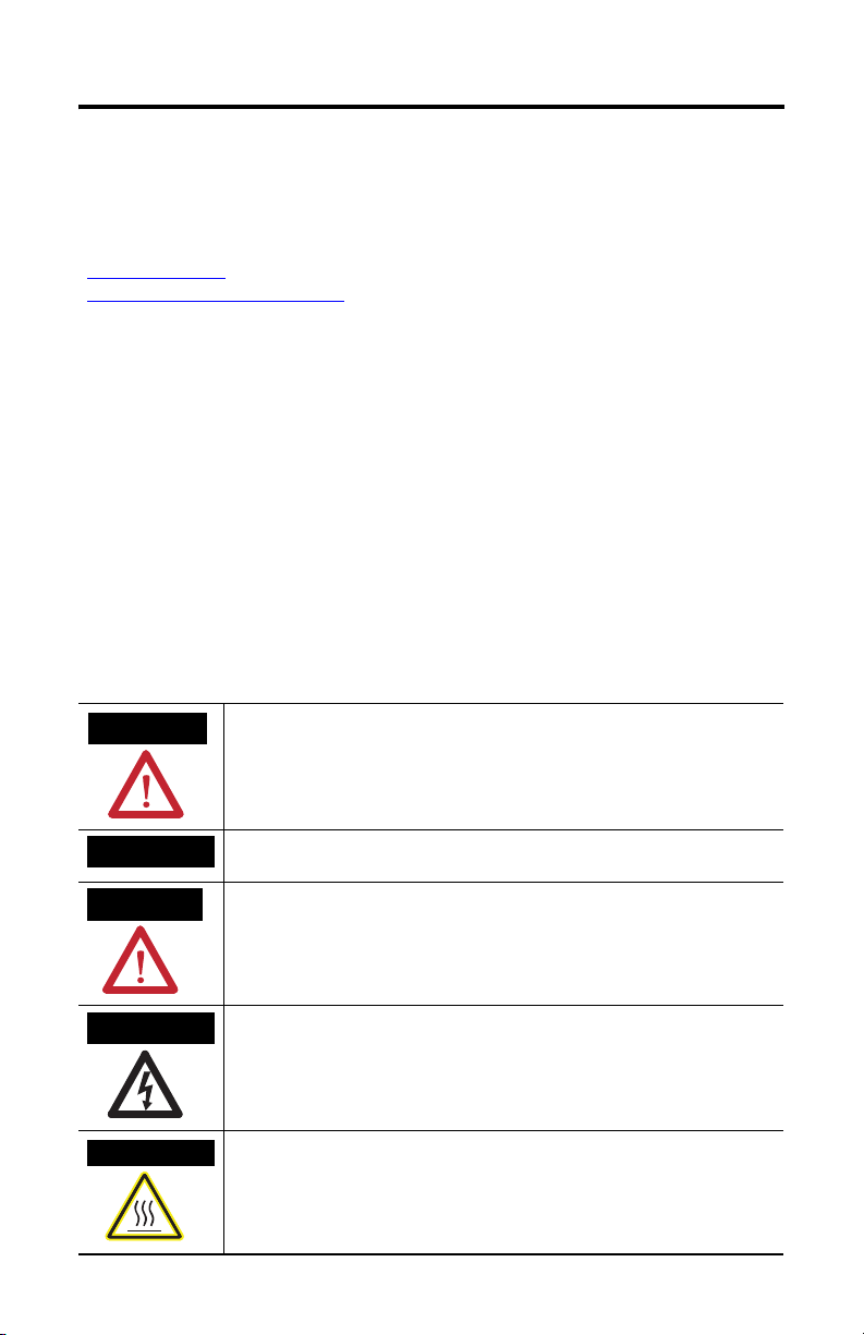
Throughout this manual, when necessary, we use notes to make you aware of safety considerations.
available from your local Rockwell Automation sales office or online at
) describes some important differences between solid state
WARNING
IMPORTANT
ATTENTION
SHOCK HAZARD
BURN HAZARD
Identifies information about practices or circumstances that can cause an explosion in
a hazardous environment, which may lead to personal injury or death, property
damage, or economic loss.
Identifies information that is critical for successful application and understanding of
the product.
Identifies information about practices or circumstances that can lead to personal injury
or death, property damage, or economic loss. Attentions help you identify a hazard,
avoid a hazard and recognize the consequences.
Labels may be on or inside the equipment (for example, drive or motor) to alert people
that dangerous voltage may be present.
Labels may be on or inside the equipment (for example, drive or motor) to alert people
that surfaces may reach dangerous temperatures.
Publication 1771-IN028D-EN-P - October 2008
Page 3
Environment and Enclosure
DC (10...30V) Input Module 3
ATTENTION
This equipment is intended for use in a Pollution Degree 2 industrial environment, in
overvoltage Category II applications (as defined in IEC publication 60664-1), at altitudes
up to 2000 m (6562 ft) without derating.
This equipment is considered Group 1, Class A industrial equipment according to
IEC/CISPR Publication 11. Without appropriate precautions, there may be potential
difficulties ensuring electromagnetic compatibility in other environments due to
conducted as well as radiated disturbance.
This equipment is supplied as open-type equipment. It must be mounted within an
enclosure that is suitably designed for those specific environmental conditions that will
be present and appropriately designed to prevent personal injury resulting from
accessibility to live parts. The enclosure must have suitable flame-retardant properties to
prevent or minimize the spread of flame, complying with a flame spread rating of 5VA,
V2, V1, V0 (or equivalent) if non-metallic. The interior of the enclosure must be accessible
only by the use of a tool. Subsequent sections of this publication may contain additional
information regarding specific enclosure type ratings that are required to comply with
certain product safety certifications.
In addition to this publication, see:
• Industrial Automation Wiring and Grounding Guidelines, for additional installation
requirements, Allen-Bradley publication 1770-4.1.
• NEMA Standards publication 250 and IEC publication 60529, as applicable, for
explanations of the degrees of protection provided by different types of enclosure.
Prevent Electrostatic Discharge
ATTENTION
This equipment is sensitive to electrostatic discharge, which can cause internal damage
and affect normal operation. Follow these guidelines when you handle this equipment:
Touch a grounded object to discharge potential static.
• Wear an approved grounding wriststrap.
• Do not touch connectors or pins on component boards.
• Do not touch circuit components inside the equipment.
• Use a static-safe workstation, if available.
• Store the equipment in appropriate static-safe packaging when not in use.
Publication 1771-IN028D-EN-P - October 2008
Page 4
4 DC (10...30V) Input Module
European Hazardous Location Approval
ATTENTION
WARNING
This equipment is intended for use in potentially explosive atmospheres as defined by
European Union Directive 94/9/EC and has been found to comply with the Essential
Health and Safety Requirements relating to the design and construction of Category 3
equipment intended for use in potentially explosive atmospheres, given in Annex II to this
Directive.
Compliance with the Essential Health and Safety Requirements has been assured by
compliance with EN 60079-15 and EN 60079-0.
Observe the following additional Zone 2 certification requirements:
• This equipment is not resistant to sunlight or other sources of UV radiation.
• This equipment must be installed in an enclosure providing at least IP54 protection
when applied in Zone 2 environments.
• This equipment shall be used within its specified ratings defined by Allen-Bradley.
• Provision shall be made to prevent the rated voltage from being exceeded by
transient disturbances of more than 40% when applied in Zone 2 environments.
• This equipment must be used only with ATEX certified backplanes.
• Secure any external connections that mate to this equipment by using screws, sliding
latches, threaded connectors, or other means provided with this product.
• Do not disconnect equipment unless power has been removed or the area is known to
be nonhazardous.
Publication 1771-IN028D-EN-P - October 2008
Page 5
DC (10...30V) Input Module 5
North American Hazardous Location Approval
The following information applies when operating
this equipment in hazardous locations.
Products marked "CL I, DIV 2, GP A, B, C, D" are suitable for use in
Class I Division 2 Groups A, B, C, D, Hazardous Locations an d
nonhazardous locations only. Each product is su pplied with
markings on the rating nameplate indicatin g the hazardous
location temperature code. When combining p roducts within a
system, the most adverse temperature code (lowest "T" number)
may be used to help determine the overa ll temperature code of
the system. Combinations of equipment in your system are subject
to investigation by the local Author ity Having Jurisdiction at the
time of installation.
WARNING
EXPLOSION HAZARD -
• Do not disconnect equipment
unless power has been removed
or the area is known to be
nonhazardous.
• Do not disconnect connections to
this equipment unless power has
been removed or the area is
known to be nonhazardous.
Secure any external connections
that mate to this equipment by
using screws, sliding latches,
threaded connectors, or other
means provided with this product.
• Substitution of components may
impair suitability for Class I,
Division 2.
• If this product contains batteries,
they must only be changed in an
area known to be nonhazardous.
Informations sur l’utilisation de cet équipement en
environnements dangereux.
Les produits marqués "CL I, DIV 2, GP A, B, C, D" ne conviennent
qu'à une utilisation en environnem ents de Classe I Division 2
Groupes A, B, C, D dangereux et non danger eux. Chaque produit
est livré avec des marquages sur sa plaque d'identificatio n qui
indiquent le code de température pour les en vironnements
dangereux. Lorsque plusieurs produits sont combi nés dans un
système, le code de température le plus défavorable (code de
température le plus faible) peut être utilisé pour déterminer le
code de température global du système. Les combinaisons
d'équipements dans le système sont sujettes à inspection par les
autorités locales qualifiées au moment de l'instal lation.
AVERTISSEMENT
RISQUE D’EXPLOSION –
• Couper le courant ou s'assurer
que l'environnement est classé
non dangereux avant de
débrancher l'équipement.
• Couper le courant ou s'assurer
que l'environnement est classé
non dangereux avant de
débrancher les connecteurs. Fixer
tous les connecteurs externes
reliés à cet équipement à l'aide
de vis, loquets coulissants,
connecteurs filetés ou autres
moyens fournis avec ce produit.
• La substitution de composants
peut rendre cet équipement
inadapté à une utilisation en
environnement de Classe I,
Division 2.
• S'assurer que l'environne ment est
classé non dangereux avant de
changer les piles.
Publication 1771-IN028D-EN-P - October 2008
Page 6

6 DC (10...30V) Input Module
Before You Begin
The 1771-IBN series C DC input module is a sink input and requires a source output. A sink
input provides a path to ground and a source output provides a positive voltage path.
You must use this module in a 1771-A1B through 1771-A4B or later 1771 I/O chassis. Refer
to the table for processor compatibility.
Processor Capability
System Type Use with Processors Cat. No.
Local Mini-PLC-2/02
Remote with a
1771-ASB
remote I/O
adapter
Mini-PLC-2/16
Mini-PLC-2/17
PLC-5/15, series B and later
PLC2/20
PLC-2/30
PLC-3
PLC-3/10
PLC-5/15, series B and later
Do not place this module in the same I/O chassis as the 1771-IX thermocouple module. You
can use this module in the same chassis as the 1771-IXE thermocouple module.
1772-LZ, 1772-LZP
1772-LX, 1772-LXP
1772-LW, 1772-LWP
1785-LT
1772-LP2
1772-LP3
1775-L1, 1775-L2, 1775-L3, 1775-L4
1775-LP4, LP8
1785-LT
This module has input filtering to limit the effect of voltage transients caused by contact
bounce and/or electrical noise. Specifications for input filtering are listed in the specifications
section of this document.
Calculate Power Supply Requirements
Your module receives its power for internal logic circuitry through the 1771 I/O chassis
backplane from the chassis power supply. The module requires 280 mA from the output of
this supply.
To calculate the requirements for the backplane power supply, add 280 mA to the power
requirements of all other modules in the I/O chassis. Calculating the requirements prevents
an overload to the chassis backplane and/or backplane power supply.
Publication 1771-IN028D-EN-P - October 2008
Page 7
DC (10...30V) Input Module 7
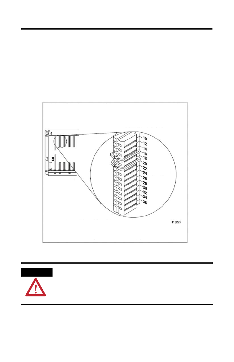
Key the Backplane Connector
Place your module in any slot in the chassis except the leftmost slot that is reserved for
processors or adapters, noting that you:
• should position the keying bands in the backplane connectors to correspond to key
slots on the module so that you place the keying bands between 14…16 and 18…20.
• can change the position of these bands if subsequent system design and rewiring
makes insertion of a different type of module necessary.
ATTENTION
Observe the following precautions when inserting or removing keys:
• Insert or remove keys with your fingers.
• Make sure that key placement is correct.
Incorrect keying or the use of a tool can result in damage to the backplane connector and
possible system faults.
Publication 1771-IN028D-EN-P - October 2008
Page 8

8 DC (10...30V) Input Module
Install the Module and Field Wiring Arm
The 1771–IBN module is a modular component of the 1771 I/O system requiring a properly
installed system chassis. Refer to Universal I/O Chassis Installation Instructions publication
1771-IN075
grounding requirements. Limit the adjacent slot-power dissipation to 10 W maximum.
for detailed information on acceptable chassis and proper installation and
WARNING
ATTENTION
IMPORTANT
If you insert or remove the module with power applied, or connect or disconnect
the field wiring arm with field-side power applied, an electrical arc can occur. This
could cause an explosion in hazardous location installations. Be sure that power is
removed or the area is nonhazardous before proceeding.
Remove power from the 1771 I/O chassis backplane before you install the module.
Failure to remove power from the backplane could cause:
• module damage.
• degradation of performance.
• injury or equipment damage due to possible unexpected operation.
Apply firm and even pressure on the module to seat it into its backplane connector.
To install the module and field wiring arm, follow this procedure.
1. Place the module in the card guides on the top and bottom of the chassis that guide
the module into position, noting the following:
• For a 1771-A1B, 1771-A2B, 1771-A3B, and 1771-A4B I/O chassis, snap the
chassis latch over the top of the module to secure it.
Publication 1771-IN028D-EN-P - October 2008
Page 9

DC (10...30V) Input Module 9
• For a 1771-A1B, 1771-A2B, 1771-A4B I/O chassis, swing the chassis locking bar
down into place to secure the modules, making sure the locking pins engage.
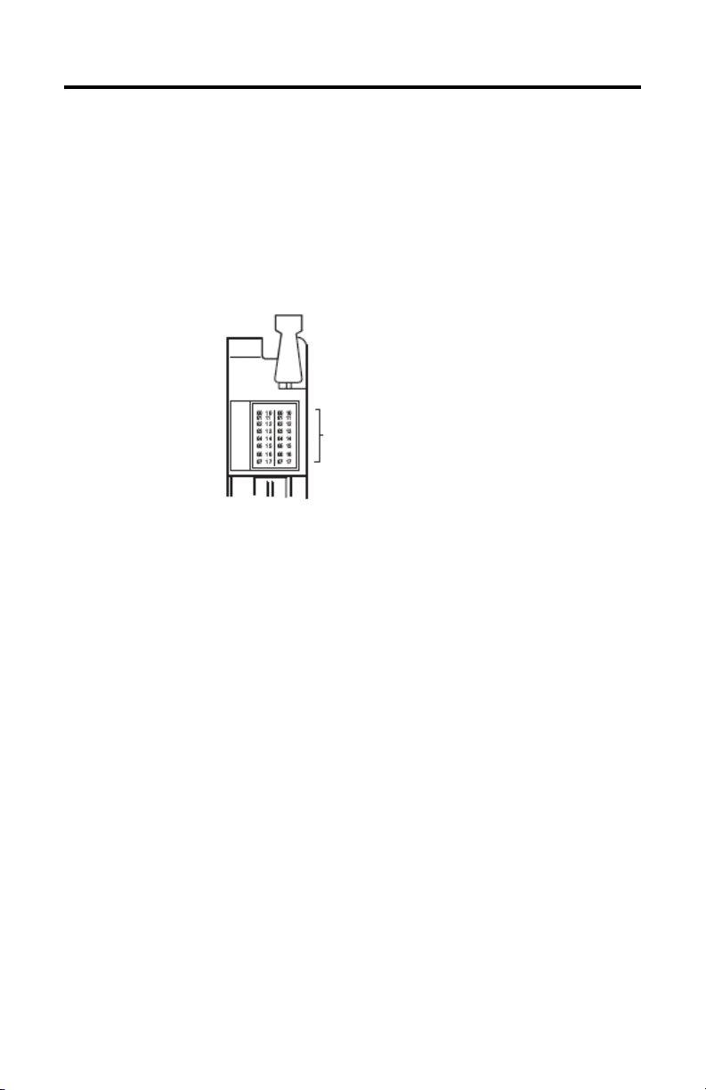
2. Attach the 1771-WN wiring arm to the horizontal bar at the bottom of the I/O
chassis noting the wiring arm pivots upward and connects with the module so you
can install or remove the module without disconnecting the wires.
Publication 1771-IN028D-EN-P - October 2008
Page 10

10 DC (10...30V) Input Module
Connecting Wiring to the Field Wiring Arm
You make connections to the module through the 1771-WN field wiring arm. The arm pivots
on the I/O chassis to connect with terminals on the front of the module and acts as a
terminal strip. The wiring arm allows the module to be removed from the chassis without
disconnecting wiring.
WARNING
WARNING
ATTENTION
The optional 1771-WHF and 1771-WHFB fused field-wiring arms are not certified for use
in hazardous location applications. Use these optional accessories only in nonhazardous
applications.
If you connect or disconnect wiring while the field-side power is on, an electrical arc
can occur. This could cause an explosion in hazardous location installations. Be sure
that power is removed or the area is nonhazardous before proceeding.
Remove power from the 1771 I/O chassis backplane and field wiring arm before
removing or installing an I/O module.
• Failure to remove power from the backplane or wiring arm could cause module
damage, degradation of performance, or injury.
• Failure to remove power from the backplane could cause injury or equipment damage
due to possible unexpected operation.
1. Be sure all power is removed from the module before making wiring connections.
2. Swing the wiring arm up into position on the front of the module, noting that the
locking tab on the module secures it into place.
3. Make your connections to the field wiring arm as shown in the connection diagram,
using the label on the front of the wiring arm to identify your wiring.
IMPORTANT
The field-wiring arm terminal identification number is not the same as the number of the
bit that controls that output.
Publication 1771-IN028D-EN-P - October 2008
Page 11

DC (10...30V) Input Module 11
I/O Module Groups
Each module condenses two full-module groups (32 inputs) into each I/O chassis slot. For
example:
• module group 1 = inputs 00…17.
• module group 2 = inputs 00…17 (module group 2 represents the second set of
inputs).
ATTENTION
Observe proper polarity with DC power connections. Reverse polarity or application of AC
voltage could damage the module.
In the graphic on the following page, note the following:
• Terminals 1…20 represent module group 1, with terminals 9, 10, 19, and
20 DC common.
• Terminals 21…40 represent module group 2, with terminals 29, 30, 39, and
40 DC common.
• Terminals on the left are even numbered 2…40 and terminals on the right
are odd numbered 1…39.
• If multiple power sources are used, do not exceed the specified isolation voltage.
• The arrow in the figure shows that actual wiring runs in this direction.
Publication 1771-IN028D-EN-P - October 2008
Page 12

12 DC (10...30V) Input Module
Connection Diagram for the 1771-IBN DC Input Module
Two -w ir e
Devices
Input 1
Input 3
DC
Supply
-
Input 5
Input 7
DC Common (-)
Input 11
Input 13
Input 15
Input 17
DC Common (-)
Input 1
Input 3
Input 5
DC
Supply
-
Input 7
DC Common (-)
Input 11
Input 13
Input 15
Three-wire
Devices
Input 17
DC Common (-)
2
4
6
8
10
12
14
16
18
20
22
24
26
28
30
32
34
36
38
40
Input 0
Input 2
Input 4
Input 6
DC Common (-)
Input 10
Input 12
Input 14
Input 16
DC Common (-)
Input 0
Input 2
Input 4
Input 6
DC Common (-)
Input 10
Input 12
Input 14
Input 16
DC Common (-)
Publication 1771-IN028D-EN-P - October 2008
Page 13

DC (10...30V) Input Module 13
Module Input Terminal Assignments
Terminal Number Input Assignment I/O Program Address
01 Input 00 1RG00
02 Input 01 1RG01
03 Input 02 1RG02
04 Input 03 1RG03
05 Input 04 1RG04
06 Input 05 1RG05
07 Input 06 1RG06
08 Input 07 1RG07
09
DC common 0 (-)
(1)
10 DC common 0 (-) 11 Input 10 1RG10
12 Input 11 1RG11
13 Input 12 1RG12
14 Input 13 1RG13
15 Input 14 1RG14
16 Input 15 1RG15
17 Input 16 1RG16
18 Input 17 1RG17
19
20
DC common 1 (-)
DC common 1 (-)
(1)
(1)
21 Input 00 1RG00
22 Input 01 1RG01
23 Input 02 1RG02
24 Input 03 1RG03
25 Input 04 1RG04
26 Input 05 1RG05
27 Input 06 1RG06
28 Input 07 1RG07
29
DC common 2 (-)
(1
-
-
-
-
Publication 1771-IN028D-EN-P - October 2008
Page 14

14 DC (10...30V) Input Module
Module Input Terminal Assignments
Terminal Number Input Assignment I/O Program Address
30
DC common 2 (-)
31 Input 10 1RG10
32 Input 11 1RG11
33 Input 12 1RG12
34 Input 13 1RG13
35 Input 14 1RG14
36 Input 15 1RG15
37 Input 16 1RG16
38 Input 17 1RG17
39
40
DC common 3 (-)
DC common 3 (-)
Where: R = rack number (such as 1, 2, 3) and G = I/O group (0…7)
(1)
You can connect a different power supply to each DC common (0, 1, and 3). Terminals 09/10 are common for terminals
01…08, 19/20 for 11…18, 29/30 for 21…28, 39/40 for 31…38.
(1
(1
(1
-
-
-
Publication 1771-IN028D-EN-P - October 2008
Page 15
DC (10...30V) Input Module 15
Status Indicators
The module has 32 status indicators on the front plate.
These represent the control status of the input. Each indicator is lit when voltage is present at
the corresponding input.
These indicators can flicker (momentarily light up) when the chassis in which the module
resides is first powered up. This flicker is normal and in no way affects the control parameters
of the system.
Red Status Indicators
Publication 1771-IN028D-EN-P - October 2008
Page 16

16 DC (10...30V) Input Module
Specifications
DC (10…30V) Input Module
Attribute Value
Inputs per module 32
Module location 1771-A1B through 1771-A4B or later I/O chassis
Input voltage range 10…30V DC
Input range, nom 4.7 mA @ 10V; 15.6 mA @ 30V
Off-state current, min 1.7 mA @ 5V DC
Off-state voltage, max 5V DC
On-state voltage, min 10V DC
Input signal delay Low to high propagation: 6 ms +
Power dissipation 16.4 W max; 1.5 W min
Thermal dissipation 53.3 BTU/hr max; 5.1 BTU/hr min
Backplane current 280 mA @ 5V DC max
Isolation voltage 60V (continuous), basic insulation type
Wire size
Field wiring arm 1771-WN
Wiring arm screw torque 1.0 N•m (9 lb•in)
Wire category
North American temp code T3C
IEC temp code T3
Enclosure type rating None (open style)
Keying 14…16
(1)
† Use this conductor category information for planning conductor routing as described in the appropriate
system-level installation manual.
(1)
High to low propagation: 6 ms +
Type tested at 500V AC for 60 s, I/O to system
2
0.25... 2.5 mm
copper wire rated at 75 °C (167 °F) or greater,
1.2 mm (3/64 in.) insulation max
2 - on signal ports
18…20
(22...14 AWG) solid or stranded
2 ms
2 ms
Publication 1771-IN028D-EN-P - October 2008
Page 17

DC (10...30V) Input Module 17
Environmental Specifications
Attribute Value
Temperature, operating IEC 60068-2-1 (Test Ad, Operating Cold),
IEC 60068-2-2 (Test Bd, Operating Dry Heat),
IEC 60068-2-14 (Test Nb, Operating Thermal Shock):
0…60 °C (32…140 °F)
Temperature, nonoperating IEC 60068-2-1 (Test Ad, Operating Cold),
IEC 60068-2-2 (Test Bd, Operating Dry Heat),
IEC 60068-2-14 (Test Nb, Operating Thermal Shock):
-40…85 °C (-40…185 °F)
Vibration IEC 60068-2-6 (Test Fc, Operating):
2 g @ 10…500 Hz
Relative humidity IEC 60068-2-30 (Test Db, Unpackaged Damp Heat):
5…95% noncondensing
Shock, operating IEC 60068-2-27 (Test Ea, Unpackaged Shock): 30 g
Shock, nonoperating IEC 60068-2-27 (Test Ea, Unpackaged Shock): 50 g
ESD immunity IEC 61000-4-2:
Radiated RF immunity IEC 61000-4-3:
EFT/B immunity IEC 61000-4-4:
Surge transient immunity IEC 61000-4-5:
Conducted RF immunity IEC 61000-4-6:
Emissions CISPR 11:
4 kV indirect contact discharges
10V/m with 1 kHz sine-wave 80% AM from
80…2000 MHz
1V/m with 1 kHz sine-wave 80% AM from
2000…2700 MHz
±1 kV at 5 kHz on signal ports
±1 kV line-line (DM) and ±2 kV line-earth (CM) on
signal ports
10V rms with 1 kHz sine-wave 80% AM
from 150 kHz…80 MHz
Group 1, Class A (with appropriate enclosure)
Publication 1771-IN028D-EN-P - October 2008
Page 18

18 DC (10...30V) Input Module
Certifications
Certification
(1)
(2)
Valu e
CSA CSA Certified Process Control Equipment. See CSA File LR54689C.
CSA Certified Process Control Equipment for Class I, Division 2 Group A,B,C,D
Hazardous Locations. See CSA File LR69960C.
Ex European Union 94/9/EC ATEX Directive, compliant with:
EN 60079-15; Potentially Explosive Atmospheres, Protection "n" (II 3 G Ex nA IIC T3 X)
EN 60079-0; General Requirements (Zone 2).
CE European Union 2004/108/EC EMC Directive, compliant with:
EN 61326-1; Meas./Control/Lab., Industrial Requirements.
EN 61000-6-2; Industrial Immunity..
EN 61000-6-4; Industrial Emissions
EN 61131-2; Programmable Controllers (Clause 8, Zone A & B.
C-Tick Australian Radiocommunications Act, compliant with:
AS/NZS CISPR 11; Industrial Emissions.
UL UL Listed Industrial Control Equipment. See UL File E65584.
(1)
See the product certification link at http://ww.ab.com for Declarations of Conformity, Certificates, and other certification
details.
(2)
When product is marked.
Publication 1771-IN028D-EN-P - October 2008
Page 19

Notes:
DC (10...30V) Input Module 19
Publication 1771-IN028D-EN-P - October 2008
Page 20
Rockwell Automation Support
Rockwell Automation provides technical information on the Web to assist you in using its
products. At http://support.rockwellautomation.com
knowledge base of FAQs, technical and application notes, sample code and links to software
service packs, and a MySupport feature that you can customize to make the best use of these
tools.
For an additional level of technical phone support for installation, configuration and
troubleshooting, we offer TechConnect support programs. For more information, contact
your local distributor or Rockwell Automation representative, or visit
ttp://support.rockwellautomation.com.
h
Installation Assistance
If you experience a problem within the first 24 hours of installation, please review the
information that's contained in this manual. You can also contact a special Customer Support
number for initial help in getting your product up and running.
, you can find technical manuals, a
United States 1.440.646.3434
Outside United
States
Monday – Friday, 8 a.m. – 5 p.m. EST
Please contact your local Rockwell Automation representative for any
technical support issues.
New Product Satisfaction Return
Rockwell Automation tests all of its products to ensure that they are fully operational when
shipped from the manufacturing facility. However, if your product is not functioning and
needs to be returned, follow these procedures.
United States Contact your distributor. You must provide a Customer Support case number
Outside United
States
Allen-Bradley, PLC, PLC-2, PLC-3, PLC-5, Rockwell Automation, and TechConnect are trademarks of Rockwell Automation, Inc.
Trademarks not belonging to Rockwell Automation are property of their respective companies.
(call the phone number above to obtain one) to your distributor in order to
complete the return process.
Please contact your local Rockwell Automation representative for the return
procedure.
Publication 1771-IN028D-EN-P - October 2008 PN-31486
Supersedes Publication 1771-IN028C-EN-P - August 2002 Copyright © 2008 Rockwell Automation, Inc. All rights reserved. Printed in the U.S.A.
 Loading...