

Page 1

AllenBradley
Configurable
Flowmeter
Module
(1771CFM/B)
User Manual
Page 2

Important User Information
Because of the variety of uses for the products described in this
publication, those responsible for the application and use of this
control equipment must satisfy themselves that all necessary steps
have been taken to assure that each application and use meets all
performance and safety requirements, including any applicable laws,
regulations, codes and standards.
The illustrations, charts, sample programs and layout examples
shown in this guide are intended solely for purposes of example.
Since there are many variables and requirements associated with any
particular installation, Allen-Bradley does not assume responsibility
or liability (to include intellectual property liability) for actual use
based upon the examples shown in this publication.
Allen-Bradley publication SGI-1.1, Safety Guidelines for the
Application, Installation, and Maintenance of Solid-State Control
(available from your local Allen-Bradley office), describes some
important differences between solid-state equipment and
electromechanical devices that should be taken into consideration
when applying products such as those described in this publication.
Reproduction of the contents of this copyrighted publication, in
whole or in part, without written permission of Allen-Bradley
Company, Inc., is prohibited.
Throughout this manual we use notes to make you aware of safety
considerations:
ATTENTION: Identifies information about practices
or circumstances that can lead to personal injury or
!
Attention statements help you to:
death, property damage or economic loss.
• identify a hazard
• avoid the hazard
• recognize the consequences
Important: Identifies information that is critical for successful
application and understanding of the product.
ControlNet is a trademark; PLC is a registered trademark of Allen-Bradley Company, Inc.
Page 3

Table of Contents
Important User Information -1. . . . . . . . . . . . . . . . . . . . . . . .
Using This Manual P-1. . . . . . . . . . . . . . . . . . . . . . . . . . . . . . .
What's In This Manual P-1. . . . . . . . . . . . . . . . . . . . . . . . . . . . . . . .
New/Updated
Abbreviations P-2
Related
Related Products P-3
Get Started P-4
Overview of the CFM Module 1-1. . . . . . . . . . . . . . . . . . . . . . .
What This Chapter Contains 1-1. . . . . . . . . . . . . . . . . . . . . . . . . . . .
How You Use the CFM Module 1-1
What's
What the CFM Module Does 1-2
Typical
Input
Capabilities
Selecting the Mode(s) of Operation 1-5
Using a Prover 1-6
Storing Current Count Values 1-6
Output
Implementing Application Features 1-8
What's
Information
. . . . . . . . . . . . . . . . . . . . . . . . . . . . . . . . . . . . . .
Documentation
. . . . . . . . . . . . . . . . . . . . . . . . . . . . . . . . . . . .
. . . . . . . . . . . . . . . . . . . . . . . . . . . . . . . . . . . . . . . .
. . . . . . . . . . . . . . . . . . . . . . . . . .
Next
. . . . . . . . . . . . . . . . . . . . . . . . . . . .
Applications
. . . . . . . . . . . . . . . . . . . . .
. . . . . . . . . . . . . . . . . . . . . . . . . . . . . . . . . . . .
. . . . . . . . . . . . . . . . . . . . . . . . .
Capabilities
. . . . . . . . . . . . . . . . . . . . .
Next
P-2. . . . . . . . . . . . . . . . . . . . . . . . . . . . . .
P-3. . . . . . . . . . . . . . . . . . . . . . . . . . . . . . .
1-2. . . . . . . . . . . . . . . . . . . . . . . . . . . . . . . . . . . . . . . .
1-3. . . . . . . . . . . . . . . . . . . . . . . . . . . . . . . . . .
1-4. . . . . . . . . . . . . . . . . . . . . . . . . . . . . . . . . . . .
1-7. . . . . . . . . . . . . . . . . . . . . . . . . . . . . . . . .
1-8. . . . . . . . . . . . . . . . . . . . . . . . . . . . . . . . . . . . . . . .
Install the CFM Module 2-1. . . . . . . . . . . . . . . . . . . . . . . . . . .
What This Chapter Contains 2-1. . . . . . . . . . . . . . . . . . . . . . . . . . . .
Understand Compliance to European Union Directive 2-2
EMC Directive 2-2
Low V
oltage Directive
Calculate Power Requirements 2-3
Set the Configuration Jumpers 2-3
Check the Module Operation Jumper 2-3
Set the Input Channel Jumpers 2-4
Determine
Key the Backplane Connector 2-6
Install the CFM Module 2-7
Make Connections to the Field Wiring Arm 2-8
Wiring Examples 2-9
What's
CFM Module Placement
Next
. . . . . . . . . . . . . . . . . . . . . . . . . . . . . . . . . . . .
. . . . . . . . . . . . . . . . . . . . . . . . . .
. . . . . . . . . . . . . . . . . . . . . . . . . .
. . . . . . . . . . . . . . . . . . . .
. . . . . . . . . . . . . . . . . . . . . . . .
. . . . . . . . . . . . . . . . . . . . . . . . . . .
. . . . . . . . . . . . . . . . . . . . . . . . . . . . . . .
. . . . . . . . . . . . . . . . . .
. . . . . . . . . . . . . . . . . . . . . . . . . . . . . . . . . .
. . . . . . . . . .
2-2. . . . . . . . . . . . . . . . . . . . . . . . . . . . . . .
2-6. . . . . . . . . . . . . . . . . . . . . . .
2-10. . . . . . . . . . . . . . . . . . . . . . . . . . . . . . . . . . . . . . . .
Page 4

Table of Contentsii
Edit Your Ladder Logic Program 3-1. . . . . . . . . . . . . . . . . . . .
What This Chapter Contains 3-1. . . . . . . . . . . . . . . . . . . . . . . . . . . .
Enter Block Transfer Instructions 3-1
PLC2 Family Processor 3-2
PLC3 Family Processor 3-3
PLC5 Family Processor 3-4
PLC5/250 Processor 3-5
What's
Next
. . . . . . . . . . . . . . . . . . . . . . . . . . . . . . .
. . . . . . . . . . . . . . . . . . . . . . . . .
. . . . . . . . . . . . . . . . . . . . . . . . . . . . .
. . . . . . . . . . . . . . . . . . . . . . . . . . . . .
. . . . . . . . . . . . . . . . . . . . . . . . . . . . .
3-6. . . . . . . . . . . . . . . . . . . . . . . . . . . . . . . . . . . . . . . .
Configure the CFM Module 4-1. . . . . . . . . . . . . . . . . . . . . . . .
What This Chapter Contains 4-1. . . . . . . . . . . . . . . . . . . . . . . . . . . .
Understand
BTW Configuration Block 4-2
Select the Mode(s) of Operation 4-8
Totalizer and Nonresettable Totalizer Modes 4-8
Highresolution Frequency Mode 4-11
Direction Sensor Mode 4-14
Configure the Module 4-16
Using
Setting Bits in the BTW Configuration Block 4-16
What's
the CFM Module'
BTW Word Description Key 4-2
BTW Word Descriptions 4-3
Counting 4-8
Frequency
Storing Count Value 4-10
Frequency
Frequency
Next
. . . . . . . . . . . . . . . . . . . . . . . . . . . . . . . . . . . . . .
Sampling
Sampling
Sampling
I/O Configuration Software
s BTW Structure 4-1. . . . . . . . . . . . . . .
. . . . . . . . . . . . . . . . . . . . . . . . . . . .
. . . . . . . . . . . . . . . . . . . . . . . . .
. . . . . . . . . . . . . . . . . . . . . . . . . . .
. . . . . . . . . . . . . . . . . . . . . . . . .
. . . . . . . . . . . . . . .
4-9. . . . . . . . . . . . . . . . . . . . . . . . . . . . .
. . . . . . . . . . . . . . . . . . . . . . . . . . . . . .
. . . . . . . . . . . . . . . . . . . . . . .
4-11. . . . . . . . . . . . . . . . . . . . . . . . . . . . .
. . . . . . . . . . . . . . . . . . . . . . . . . . . . . .
4-14. . . . . . . . . . . . . . . . . . . . . . . . . . . . .
. . . . . . . . . . . . . . . . . . . . . . . . . . . . . . . . .
4-16. . . . . . . . . . . . . . . . . . . . . . .
. . . . . . . . . . . . . . .
4-16. . . . . . . . . . . . . . . . . . . . . . . . . . . . . . . . . . . . . . . .
Interpret Module Status and Input Data 5-1. . . . . . . . . . . . . . .
What This Chapter Contains 5-1. . . . . . . . . . . . . . . . . . . . . . . . . . . .
Understand
BTR Word Description Key 5-2
BTR Word Descriptions 5-3
What's
the CFM Module'
Next
s BTR Structure 5-1. . . . . . . . . . . . . . . .
. . . . . . . . . . . . . . . . . . . . . . . . . . .
. . . . . . . . . . . . . . . . . . . . . . . . . . . . .
5-6. . . . . . . . . . . . . . . . . . . . . . . . . . . . . . . . . . . . . . . .
Troubleshoot the CFM Module 6-1. . . . . . . . . . . . . . . . . . . . . .
What This Chapter Contains 6-1. . . . . . . . . . . . . . . . . . . . . . . . . . . .
Status Indicators 6-1
Diagnostics 6-2
Diagnostic Words in the BTR File 6-2
What's
Next
. . . . . . . . . . . . . . . . . . . . . . . . . . . . . . . . . . . .
. . . . . . . . . . . . . . . . . . . . . . . . . . . . . . . . . . . . . . . .
. . . . . . . . . . . . . . . . . . . . . . .
6-2. . . . . . . . . . . . . . . . . . . . . . . . . . . . . . . . . . . . . . . .
Page 5

Table of Contents iii
Specifications A-1. . . . . . . . . . . . . . . . . . . . . . . . . . . . . . . . . .
What This Appendix Contains A-1. . . . . . . . . . . . . . . . . . . . . . . . . . .
Frequency Accuracy A-1
General
Specifications
. . . . . . . . . . . . . . . . . . . . . . . . . . . . . . . . .
A-2. . . . . . . . . . . . . . . . . . . . . . . . . . . . . . . .
Schematics B-1. . . . . . . . . . . . . . . . . . . . . . . . . . . . . . . . . . . .
What This Appendix Contains B-1. . . . . . . . . . . . . . . . . . . . . . . . . . .
Input
Circuits
Flowmeter
Gate
Output
Discrete
DC to DC Converters (24V dc power supplies) B-4
Inputs
Inputs
Circuits
Outputs
. . . . . . . . . . . . .
B-1. . . . . . . . . . . . . . . . . . . . . . . . . . . . . . . . . . . . . . .
B-1. . . . . . . . . . . . . . . . . . . . . . . . . . . . . . . . . .
B-3. . . . . . . . . . . . . . . . . . . . . . . . . . . . . . . . . . . . . .
B-4. . . . . . . . . . . . . . . . . . . . . . . . . . . . . . . . . . . . . .
B-4. . . . . . . . . . . . . . . . . . . . . . . . . . . . . . . . . .
Replace Your QRC Module C-1. . . . . . . . . . . . . . . . . . . . . . . . .
What This Appendix Contains C-1. . . . . . . . . . . . . . . . . . . . . . . . . . .
What the CFM Module Does C-1
Check Power Requirements C-1
Remove Your QRC Module C-2
Set the Configuration Jumpers C-3
Set the Module Operation Jumper C-3
Check the Input Channel Jumpers C-4
Install
the CFM Module
Make Connections to the New Wiring Arm C-6
Wiring Example C-7
Resume Normal Operation C-8
Edit Your Ladder Logic Program C-8
Read Data From the CFM Module C-9
BTR Word Descriptions C-9
Interpret Status Indicators C-10
Additional Feature C-10
. . . . . . . . . . . . . . . . . . . . . . . . . . . . . . . . . . .
. . . . . . . . . . . . . . . . . . . . . . . . . . . .
. . . . . . . . . . . . . . . . . . . . . . . . . . . .
. . . . . . . . . . . . . . . . . . . . . . . . . . . .
. . . . . . . . . . . . . . . . . . . . . . . . . .
. . . . . . . . . . . . . . . . . . . . . .
. . . . . . . . . . . . . . . . . . . . . .
C-5. . . . . . . . . . . . . . . . . . . . . . . . . . . . . . . .
. . . . . . . . . . . . . . . . . .
. . . . . . . . . . . . . . . . . . . . . . . . . . . . .
. . . . . . . . . . . . . . . . . . . . . . .
. . . . . . . . . . . . . . . . . . . . . .
. . . . . . . . . . . . . . . . . . . . . . . . . . .
. . . . . . . . . . . . . . . . . . . . . . . . . . . .
. . . . . . . . . . . . . . . . . . . . . . . . . . . . . . . . .
Replace Your QRD Module D-1. . . . . . . . . . . . . . . . . . . . . . . . .
What This Appendix Contains D-1. . . . . . . . . . . . . . . . . . . . . . . . . . .
What the CFM Module Does D-1
Check Power Requirements D-2
Remove Your QRD Module D-2
Set the Configuration Jumpers D-3
Set the Module Operation Jumper D-3
Check the Input Channel Jumpers D-4
Install
the CFM Module
Make Connections to the New Wiring Arm D-6
Wiring Examples D-7
Resume Normal Operation D-8
. . . . . . . . . . . . . . . . . . . . . . . . . . . . . . . . . .
. . . . . . . . . . . . . . . . . . . . . . . . . . . .
. . . . . . . . . . . . . . . . . . . . . . . . . . . .
. . . . . . . . . . . . . . . . . . . . . . . . . . . .
. . . . . . . . . . . . . . . . . . . . . . . . . .
. . . . . . . . . . . . . . . . . . . . . .
. . . . . . . . . . . . . . . . . . . . . .
D-5. . . . . . . . . . . . . . . . . . . . . . . . . . . . . . . .
. . . . . . . . . . . . . . . . . .
. . . . . . . . . . . . . . . . . . . . . . . . . . . . .
Page 6

Table of Contentsiv
Edit Your Ladder Logic Program D-8. . . . . . . . . . . . . . . . . . . . . . .
Read Data From the CFM Module D-9
BTR Word Description Key D-9
BTR Word Descriptions D-10
Reset Total and Overflow Flags D-10
BTW Word Description D-10
Interpret Status Indicators D-11
Additional Feature D-11
. . . . . . . . . . . . . . . . . . . . . . . . . . . .
. . . . . . . . . . . . . . . . . . . . . . . . . . . .
. . . . . . . . . . . . . . . . . . . . . . . . . . . . . . . . .
. . . . . . . . . . . . . . . . . . . . . .
. . . . . . . . . . . . . . . . . . . . . . . . .
. . . . . . . . . . . . . . . . . . . . . . . . . . .
. . . . . . . . . . . . . . . . . . . . . . . .
Using I/O Configuration Software E-1. . . . . . . . . . . . . . . . . . .
What This Appendix Contains E-1. . . . . . . . . . . . . . . . . . . . . . . . . . .
Configure
the CFM Module
Block Transfer Data Screen E-1
Channel Setup Screen E-2
Output Setup Screen E-5
Monitor Screen E-6
. . . . . . . . . . . . . . . . . . . . . . . . . . . . . . . . . . .
. . . . . . . . . . . . . . . . . . . . . . . . . .
. . . . . . . . . . . . . . . . . . . . . . . . . . . . . .
. . . . . . . . . . . . . . . . . . . . . . . . . . . . . . .
E-1. . . . . . . . . . . . . . . . . . . . . . . . . . . . .
Page 7
Using This Manual
Preface
What's In This Manual
Use this manual to install, program and troubleshoot your
Configurable Flowmeter module (1771-CFM/B).
Important: We assume that you know how to program and operate
an Allen-Bradley PLC
processor. If you do not, see
the appropriate programming and operations manual for
the PLC processor you are using, before you attempt to
use this manual.
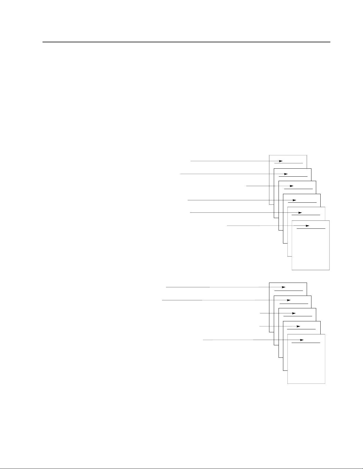
To Read chapter
Understand the CFM module
Install the CFM module
Edit your ladder logic to contain block transfer instructions
for the CFM module
Configure the CFM module
Read data from your module
Interpret status indicators and diagnostic codes
1
2
3
4
5
6
Specifications
Schematics
Using the CFM module as a replacement for the QRC module
Using the CFM module as a replacement for the QRD module
Using I/O Configuration software
See appendixFor reference on
A
B
C
D
E
Publication 17716.5.99 December 1995
Page 8

Using This ManualP–2
New/Updated Information
Abbreviations
The1771-CFM/B is marked with the
logo, indicating that this
version complies with the European Union Directives. Technical
additions and corrections are marked with change bars.
To comply with the European Union Directives, this information in
the manual has been updated:
Updated information On page(s)
European Union Directives compliance
CFM module field wiring arm connections 2-8
CFM module wiring examples 2-9
General specifications A-1
CFM (QRC) module wiring arm connections C-6
CFM (QRD) module wiring arm connections D-6, D-7
We refer to As
Configurable Flowmeter module (1771CFM/B)
Configurable Flowmeter module emulating a 1771QRC module CFM (QRC) module
Configurable Flowmeter module emulating a 1771QRD module CFM (QRD) module
AllenBradley programmable logic controllers PLC processors
1771QRD Pulse Flowmeter module QRD module
Bulletin 1771 Dual Ratemeter module (1771QRC) QRC module
2-2
CFM module
Publication
17716.5.99 December 1995
Page 9

Using This Manual P–3
Related Documentation
Related Products
Document Publication number
Configurable Flowmeter Module Product Data 17712.226
PLC2 Programming Software Documentation Set (D6200L06)
PLC2 Programming Software Programming Manual
PLC3 Programming Software Documentation Set (D6200L07)
PLC3 Programming Software Programming Manual
PLC5 Programming Software Documentation Set
(6200N8.001)
PLC5 Programming Software I/O Configuration Manual
PLC5/250 Programming Software Documentation Set
(6200N8.002)
PLC5/250 Programming Software Programming Manual
SCADA Custom Application Routines (CARs) for Gas and Liquid
Petroleum Flow Calculations Product Profile
PLC5 Volume Flow CARs for Orifice Metering User Manual 62006.5.17
PLC5 Volumetric Flow CARs for Turbine and Displacement
Metering User Manual
62006.4.14
62006.4.17
62006.4.12
50006.4.8
62001.22
62006.5.18
See the Automation Group Publication Index (publication SD499)
for additional publications with information on PLC processors.
You can install the CFM module in any system that uses
PLC processors with block-transfer capability and the
1771 I/O structure. Contact your local Allen-Bradley representative
for more information about our PLC processors.
Publication
17716.5.99 December 1995
Page 10
Using This ManualP–4
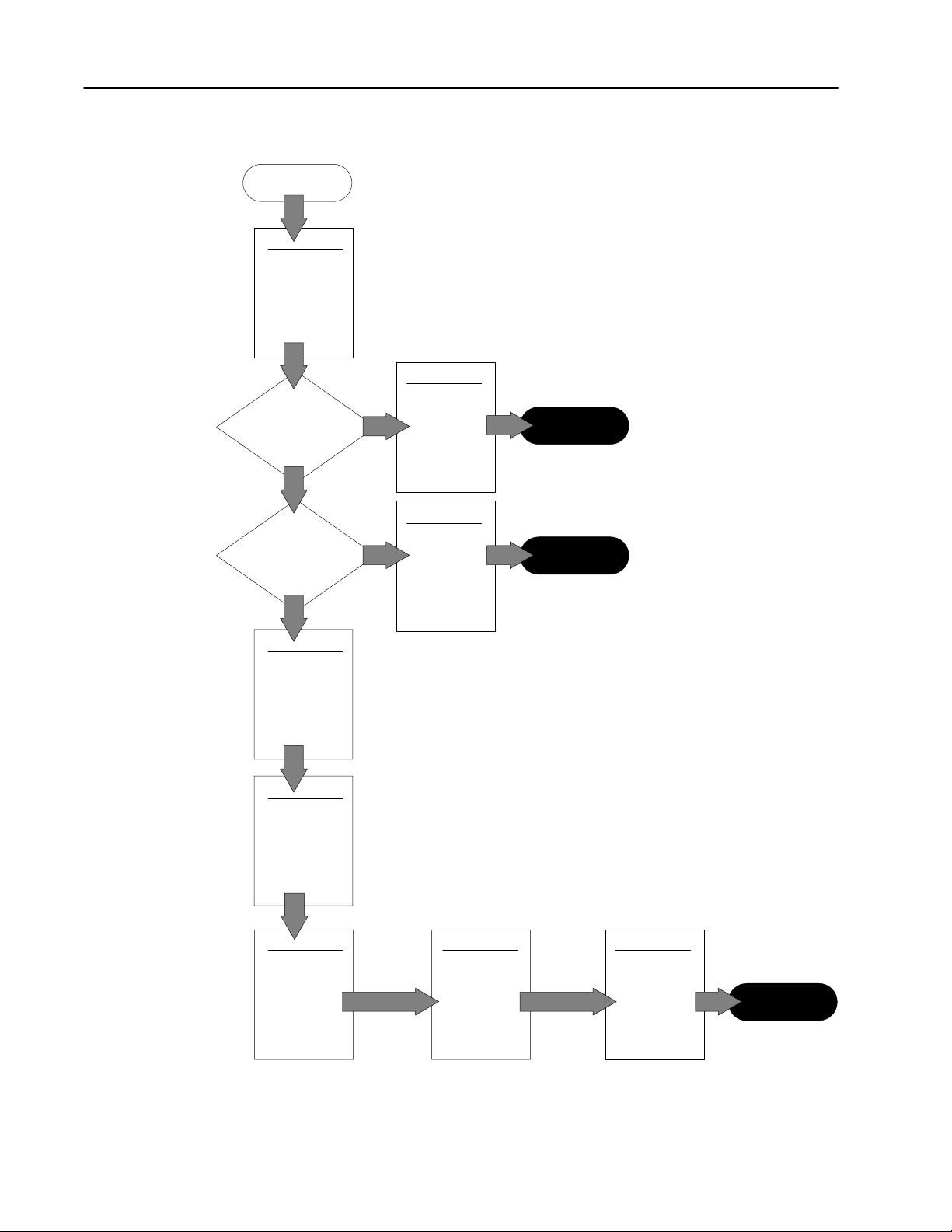
Get Started
Start
Overview of the
CFM Module
Using
CFM module
as replacement for
QRC module?
N
Using CFM module
as replacement for
QRD module?
Use this diagram to help you get started.
1
A
Y
Replace Y
our
Y
QRC Module
Replace Y
our
QRD Module
B
Complete
Complete
N
Install the
CFM Module
Edit Y
our
Ladder Logic
Program
Configure the
CFM Module
2
3
4 5 6
Interpret
Module
Status and
Input Data
T
roubleshoot
the CFM Module
Complete
Publication
17716.5.99 December 1995
Page 11
Chapter
Overview of the CFM Module
1
What This Chapter Contains
How You Use the CFM Module
1
Make sure the module operation
jumper is set in the CFM position.
Read this chapter to familiarize yourself with the CFM module.
For information on See page
How You Use the CFM Module . . . . . . . . . . . . . . . . . . . . . . . 1-1
What's Next . . . . . . . . . . . . . . . . . . . . . . . . . . . . . . . . . . . . 1-2
What the CFM Module Does . . . . . . . . . . . . . . . . . . . . . . . . 1-2
Typical Applications . . . . . . . . . . . . . . . . . . . . . . . . . . . . . . . 1-3
Input Capabilities . . . . . . . . . . . . . . . . . . . . . . . . . . . . . . . . 1-4
Selecting the Mode(s) of Operation . . . . . . . . . . . . . . . . . 1-5
Using a Prover . . . . . . . . . . . . . . . . . . . . . . . . . . . . . . . . 1-6
Storing Current Count Values . . . . . . . . . . . . . . . . . . . . . 1-6
Output Capabilities . . . . . . . . . . . . . . . . . . . . . . . . . . . . . . . 1-7
Implementing Application Features . . . . . . . . . . . . . . . . .
1-8
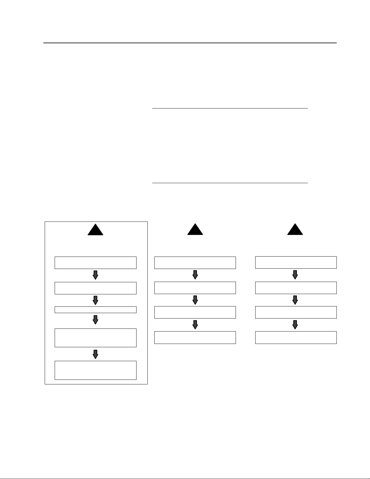
The CFM module is designed to operate in one of three ways:
2
as a replacement for a QRC module
Set the module operation jumper in
the QRC position.
as a replacement for a QRD moduleas a CFM module
Set the module operation jumper in
the QRD position.
3
Wire input and outputs to swing arm
(1771WN).
Install the CFM module.
Edit your ladder logic to contain
BTW and BTR instructions for the
CFM module.
Edit CFM module's BTW configuration
block and send configuration BTW to
the CFM module.
Wire inputs to the new swing arm
(1771WN).
Replace the QRC module with the
CFM module.
Continue to program BTRs as before
(no changes to ladder logic).
Important: If you use the CFM module as a replacement for a QRC or QRD module,
the CFM module operates like a QRC or QRD module. You do not use
any of the CFM module's features; therefore, you cannot configure outputs
to any of the four input channels.
Wire inputs to the new swing arm
(1771WN).
Replace the QRD module with the
CFM module.
Continue to program BTWs and BTRs
as before (no changes to ladder logic).
Publication
17716.5.99 - December 1995
Page 12
1–2 Overview of the CFM Module
What's Next
The rest of this chapter contains information on
CFM module operation.
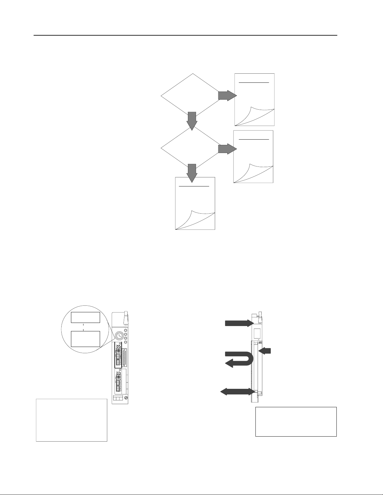
C
Using the
CFM module
as a replacement for
a QRC module?
N
Using the
CFM module
as replacement for
a QRD module?
N
Y
Y
1
D
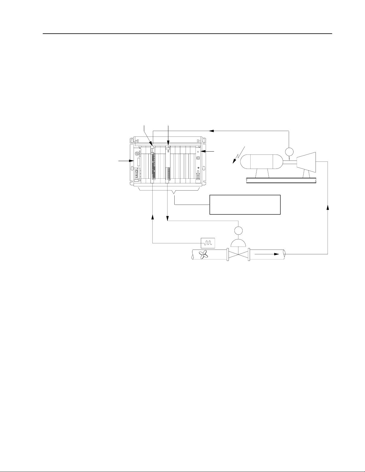
What the CFM Module Does
Data T
able
User Program
❻ Your ladder program can use or
move the data before it is
written over by the transfer of
new data in a subsequent
transfer.
The CFM module interfaces
with these PLC processors:
• PLC2 processor family
• PLC3 processor family
• PLC5
• PLC5/250
processor family
processors
PLC5/40
processor
The CFM module performs high-speed totalizing and/or rate
calculation operations for various industrial applications. The CFM
module is a single-slot I/O module that interfaces between an
Allen-Bradley PLC processor that has block-transfer capability and
external I/O devices.
1771CFM
❶
The PLC processor transfers your
configuration data and output channel
data to the CFM module using a block
transfer write (BTW) instruction.
❹ When instructed by your ladder program,
the PLC processor performs a block
transfer read (BTR) of the values
(count and/or frequency in binary format)
and stores them in a data table.
BTW
BTR
External devices generate
❷
input signals that are
transmitted to the
CFM module.
❸ The CFM module performs
❺ The PLC processor and CFM module
determine that the transfer was made
without error.
The CFM module interfaces with:
• magnetic pickup flowmeters
• 440V dc pulses (TTL compatible)
• proximity probes
calculations on
accumulated pulse
counts.
1
Publication
17716.5.99 - December 1995
Page 13
1–3Overview of the CFM Module
Typical Applications
PLC5/30
processor
You can use the CFM module in the power management, automotive,
food and beverage, and oil and gas industries for various flow and/or
turbine metering applications. Some sample applications include:
• turbine shaft speed monitoring
• automotive paint booths
• brewery flow monitoring
• petrochemical flow and custody transfer
1771CFM
1771OFE
shaft speed
power
supply
generator
electricity
PLC controller monitors shaft
speed, performs PID calculations
and adjusts valve.
shaft
encoder
turbine
monitors fuel flow
and total gallons
pulse output
fuel
CV
19885
Publication
17716.5.99 - December 1995
Page 14
1–4 Overview of the CFM Module
Input Capabilities
The CFM module accepts input for up to four channels
(mode dependent). Each of the four input channels may accept these
input signals:
•magnetic pickup — 50mV to 200V ac peak (optional 500mV to
200V ac peak for improved noise immunity)
•4-40V dc pulses with open collector (TTL compatible)
•proximity probe inputs
–compatible with Bently Nevada 3300 (5mm and 8mm)
proximity transducer systems
–provides two isolated 24V dc power supplies (rated at 12mA)
to power external devices
You configure the CFM module’s four input channels for your
specific application(s). Each input channel has two input selections:
flowmeter input (F0F3) you connect
your input device to this input (ac, TTL)
gate input (G0G3) accepts 440V dc
input pulse from open collector or external
contact closure. Used in Totalizer and
Nonresettable Totalizer modes to:
•store the current count of an input channel
upon impulse on gate
•interface to a prover when a prover is
enabled used to store the count as the
spheroid is sensed in the prover tube
four input channels
flowmeter input (F0)
gate input (G0)
flowmeter input (F1)
gate input (G1)
flowmeter input (F2)
gate input (G2)
flowmeter input (F3)
gate input (G3)
➀
Channel 0
Channel 1
Channel 2
Channel 3
➀
See
pages
2-9
and
2-10 for wiring diagrams.
Publication
17716.5.99 - December 1995
Page 15

Selecting the Mode(s) of Operation
You configure the CFM module for these modes of operation:
1–5Overview of the CFM Module
Use this mode To
• accurately measure counts using a flowmeter
or positive displacement meter
• trigger outputs directly from the CFM module
trigger on total, frequency, acceleration
Totalizer
Nonresettable Totalizer
Highresolution Frequency
(channels 0&1 or channels 2&3)
Direction Sensor
(channels 0&1 or channels 2&3)
➀
This mode uses two channels for one input (your input device is connected to F0 or F2, while F1 or F3 is unused).
➀
➀
• monitor flow total, rate, and rate of change
independent of your PLC processor scan times
• store counts based on external input
• scale the frequency and count to
engineering units
• interface to a prover
operate in the Totalizer mode with the count
reset function disabled to prevent loss of
accumulated value
• monitor the frequency of an input with high
accuracy (e.g. shaft)
• monitor the rate of speed change
• operate outputs based on speed or
rate of change
• scale the frequency to engineering units
• monitor the direction of shaft rotation
• monitor rate of change and frequency
• trigger outputs based on direction, frequency,
rate of change
• scale the frequency and count to
engineering units
Indicators/
Alarms
overrange
overflow
overspeed
acceleration
overrange
overflow
overspeed
acceleration
overspeed
overrange
acceleration
overspeed
acceleration
overrange
Prover
√ √ √ √
√ √ √
Total
reset
Scaler
values
√
√
Rollover
value
Publication
17716.5.99 - December 1995
Page 16
1–6 Overview of the CFM Module
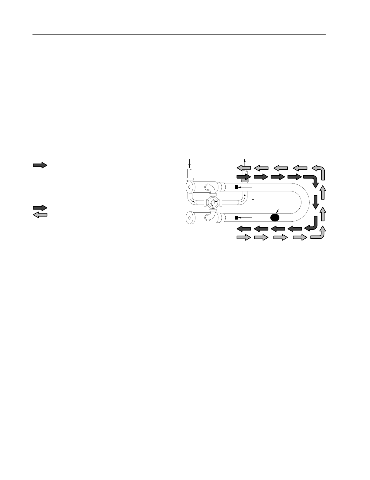
Using a Prover
A prover is used for the calibration of liquid meters in custody
transfer applications. This calibration is done by comparing a
metered throughput to a known volume in the prover. The number
of pulses accumulated (Prover Total Count Value), while the
spheroid moves between two detectors, is then compared to the
predetermined volume of the prover section to ascertain the
meter factor.
If you are using the Totalizer or Nonresettable Totalizer mode for
capturing meter counts during a prover calibration, you have the
option of selecting either of these types of provers:
unidirectional the CFM module:
• begins counting when the spheroid passes the
first detector
• stops counting when the spheroid passes the second
detector (Prover Total Count Value is updated at
this time)
bidirectional the CFM module:
• begins counting when the spheroid passes the first detector
• stops counting when the spheroid passes the second
detector (Prover Total Count Value is updated at this time -
intermediate value returned)
• continues counting when the spheroid returns past the
second detector
• stops counting when the spheroid returns past the first
detector (Prover Total Count Value is updated at this time)
detectors
spheroid
19884
Storing Current Count Values
If you are using the Totalizer or Nonresettable Totalizer mode and
you are not using a prover, you can use the gate input to store the
current count value of any (or all) of the four input channels.
The current count value of each channel is placed in a separate word
in the BTR file (Store Count Value). The Store Count Value will
remain in the BTR file until a new trigger pulse is received at the
gate input. The Store Count Value is then updated to reflect the
new value.
Publication
17716.5.99 - December 1995
Page 17

1–7Overview of the CFM Module
Output Capabilities
The CFM module has four assignable outputs. These outputs are
designed for applications that require fast response. The outputs:
• are electrically fused/current limited to 3A (output combinations
are limited to 7A)
• can be assigned to any input channel with user-selectable turn-on
and turn-off values
• are current sourcing at 5-40V dc (1A maximum per output)
• must be connected to an external power supply
• are in groups of two — this lets you use two separate external
power supplies if desired (one for outputs 0&1 and one for
outputs 2&3)
Outputs may be forced on or off independent of count or
frequency value. They may be forced on and off by setting bits in the
BTW configuration block.
Important: You can assign as many as four outputs to a given
channel; however, you can not use the same output with
two different channels.
In this mode
of operation
Totalizer
Nonresettable Totalizer
Highresolution
Frequency
Direction Sensor
You can assign outputs that are programmable to trigger
on total, rate, rate change (acceleration), total overflow or
prover status
on total, rate, rate change (acceleration), total overflow or
prover status
on frequency or frequency rate of change (acceleration)
on either CLOCKWISE or COUNTERCLOCKWISE direction,
acceleration or frequency (outputs are triggered ON only)
Publication
17716.5.99 - December 1995
Page 18

1–8 Overview of the CFM Module
Totalizer
(programmable rollover)
This bit will toggle
count rollover
tivat
overrange alarm
all
frequency > 100kHz
Implementing Application Features
You can use the CFM module to implement programmable
application features that are usually initiated by your PLC processor.
This frees the PLC processor to do other tasks and helps increase the
overall throughput of your PLC system.
This feature Is used in these modes To Alarm is ON when
overflow indication
overrange alarm all
overspeed alarm all
acceleration alarm all
Totalizer
Nonresettable Totalizer
set an overflow flag when the count is greater
than the highest allowable count
(programmable rollover). This bit will toggle
with each successive rollover (010101).
The count continues from zero. This bit can be
reset in the BTW configuration block.
tivt vrrn lrm wh
e overrange alarm when rate is greater
ac
than allowable Hertz (fixed at 100kHz).
activate overspeed alarm when frequency is
higher than userspecified frequency value.
activate acceleration alarm when acceleration is
greater than userspecified acceleration value.
.
n rt i rtr
count = rollover
(default 10,000,000)
frequency > 100kHz
frequency > userspecified value
|acceleration| >
userspecified value
What's Next
2
Install the
CFM Module
Publication
17716.5.99 - December 1995
Page 19

Chapter
Install the CFM Module
2
What This Chapter Contains
Follow the instructions in this chapter to install the CFM module.
To install the CFM module See page
Understand Compliance to European Union Directive . . . . . .
Calculate Power Requirements . . . . . . . . . . . . . . . . . . . . . . 2-3
Set the Configuration Jumpers . . . . . . . . . . . . . . . . . . . . . . . 2-3
Check the Module Operation Jumper . . . . . . . . . . . . . . . . 2-3
Set the Input Channel Jumpers . . . . . . . . . . . . . . . . . . . . 2-4
Determine CFM Module Placement . . . . . . . . . . . . . . . . . . . 2-6
Key the Backplane Connector . . . . . . . . . . . . . . . . . . . . . . . 2-6
Install the Module . . . . . . . . . . . . . . . . . . . . . . . . . . . . . . . . 2-7
Make Connections to the Field Wiring Arm . . . . . . . . . . . . . .
ATTENTION: Electrostatic discharge can damage
integrated circuits or semiconductors if you touch
!
backplane connector pins. Follow these guidelines
when you handle the CFM module.
2-2
2-8
• Touch a grounded object to discharge static potential.
• Wear an approved wrist-strap grounding device.
• Do not touch the backplane connector or
connector pins.
• Do not touch circuit components inside the module.
• If available, use a static-safe work station.
• When not in use, keep the CFM module in its
static-shield bag.
Publication
17716.5.99 - December 1995
Page 20

2–2 Install the CFM Module
Understand Compliance to European Union Directive
If this product has the CE mark it is approved for installation within
the European Union and EEA regions. It has been designed and
tested to meet the following directives.
EMC Directive
This product is tested to meet Council Directive 89/336/EEC
Electromagnetic Compatibility (EMC) and the following standards,
in whole or in part, documented in a technical construction file:
• EN 50081-2
EMC – Generic Emission Standard, Part 2 – Industrial
Environment
• EN 50082-2
EMC – Generic Immunity Standard, Part 2 – Industrial
Environment
This product is intended for use in an industrial environment.
Low Voltage Directive
This product is tested to meet Council Directive 73/23/EEC
Low Voltage, by applying the safety requirements of EN 61131–2
Programmable Controllers, Part 2 – Equipment Requirements
and Tests.
For specific information that this EN requires, see the appropriate
sections in this publication, as well as the following
Allen-Bradley publications:
• Industrial Automation Wiring and Grounding Guidelines
(for noise immunity), publication 1770-4.1
• Guidelines for Handling Lithium Batteries, publication AG-5.4
• Automation Systems Catalog, publication B111
Publication
17716.5.99 - December 1995
Page 21

2–3Install the CFM Module
Calculate Power Requirements
Set the Configuration Jumpers
Your CFM module receives its power through the 1771 I/O chassis
backplane from the chassis power supply. The maximum current
drawn by the CFM module is 1.0A.
Add this value to the requirements of all other modules in the I/O
chassis to prevent overloading the chassis backplane and/or
backplane power supply.
ATTENTION: When using a 1771-P7 or 1771-PS7
power supply to power an I/O chassis, you cannot
!
place more than four CFM modules in this chassis.
The interaction between the four CFM modules and the
1771-P7 or 1771-PS7 power supply (not 16A limit)
prevents the power supply from powering up.
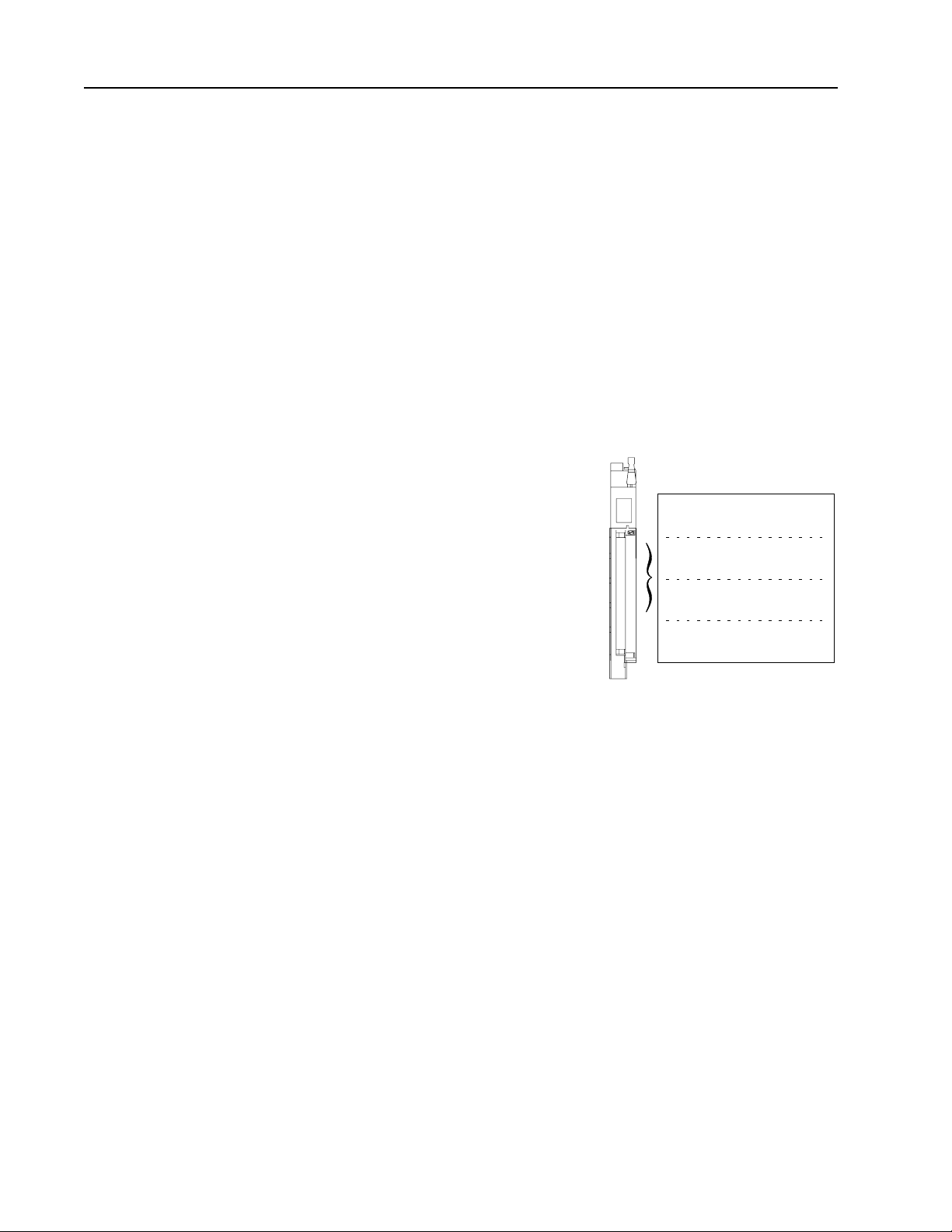
You check or set these jumpers:
• module operation jumper
• input channel jumpers
Check the Module Operation Jumper
Important: Make sure the module operation jumper is in the
CFM position (default setting).
CFM
QRD
QRC
If The Jumper Is
Set In This Position
QRC
QRD a QRD module (1 word BTW / 9 word BTR)
The CFM Module
Will Operate As
a QRC module (no BTW / 3 word BTR)
19807
Publication
17716.5.99 - December 1995
Page 22
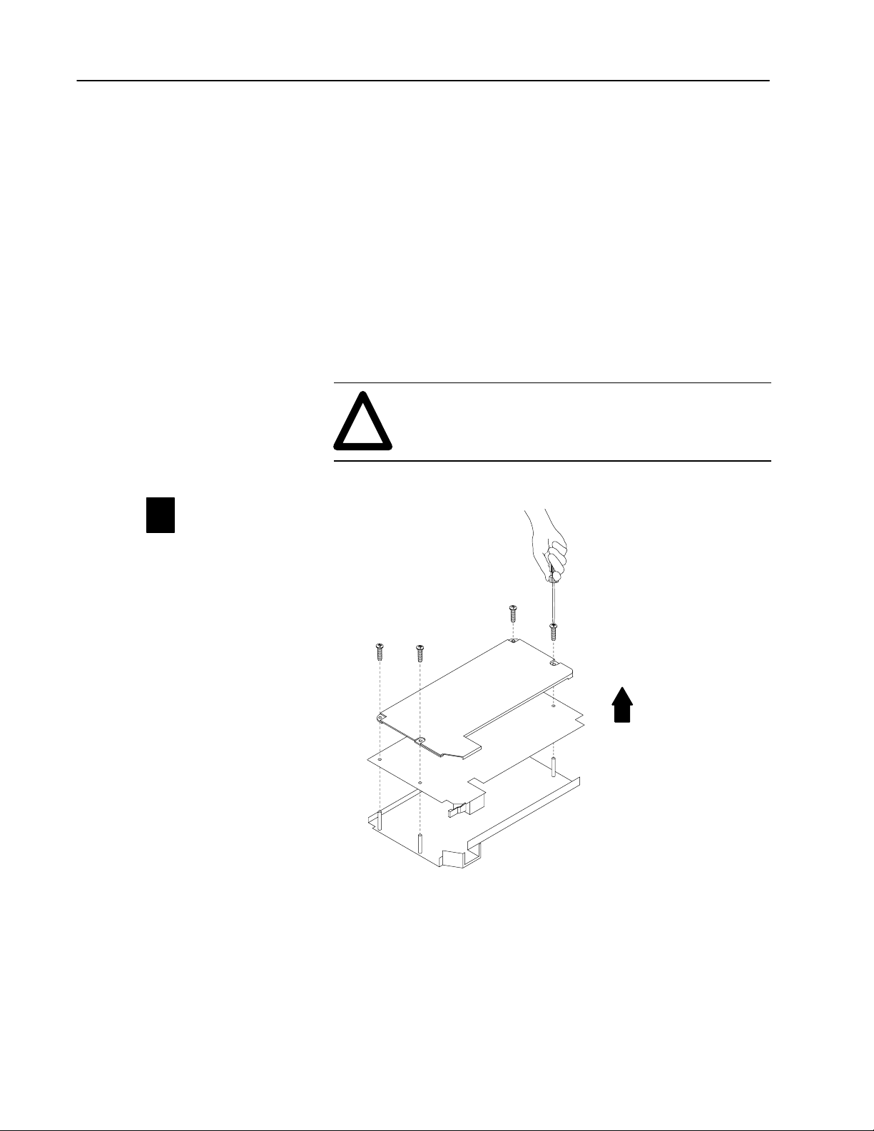
2–4 Install the CFM Module
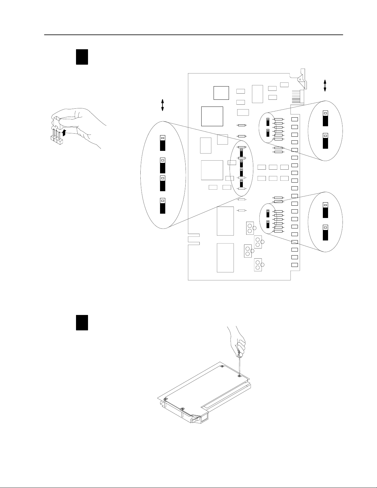
Set the Input Channel Jumpers
The CFM module has user-selectable jumpers for each flowmeter
and gate input:
• flowmeter jumpers (F0-F3) — set jumper for low-pass filter
(70Hz) or high-speed operation
• gate jumpers (G0-G3) — set jumper for +5-12V or
+12-40V operation
The CFM module is configured for high-speed operation. If any
input channel will be accepting input from a mechanical switch, you
need to set the flowmeter jumper for that input channel to filter
operation. The filter provides debouncing for the mechanical switch.
ATTENTION: The frequency of counting must be
less than 70Hz when the filter mode is selected. If the
!
frequency exceeds 70Hz, the CFM module will not
read the incoming pulse.
Remove the four screws securing the side cover
11
to the module and remove the covers.
19805
Publication
17716.5.99 - December 1995
Page 23
Reposition the flowmeter and gate jumpers associated
2
with each input channel according to your requirements.
The flowmeter and gate jumpers
➁
can be
set independent of each other (you can
select the filter action for each flowmeter
input and a voltage for each and gate
input independently).
➀
FILTER
HIGH SPEED
F1
F0
F3
2–5Install the CFM Module
5-12V
12-40V
G0
G1
gate jumpers
G2
Reposition the cover and secure with
13
the fours screws removed in step 1.
F2
flowmeter jumpers
➀
In
the filter position, the module will not read frequencies above 70Hz.
➁
Jumpers are shown in default settings.
G3
19806
19813
Publication
17716.5.99 - December 1995
Page 24
2–6 Install the CFM Module
ith
bit
ith
bit
icti
block transfer module
16bit or block transfer module
Determine CFM Module Placement
Place your module in any slot of the I/O chassis except for the
extreme left slot. This slot is reserved for processors or adapter
modules.
Use of data table 2slot addressing 1slot addressing 1/2slot addressing
Input Image Bits 8
Output Image Bits 8
Read Block Words 41 max
Write Block Words
60 max
Place the CFM module in any
module group w
block transfer module.
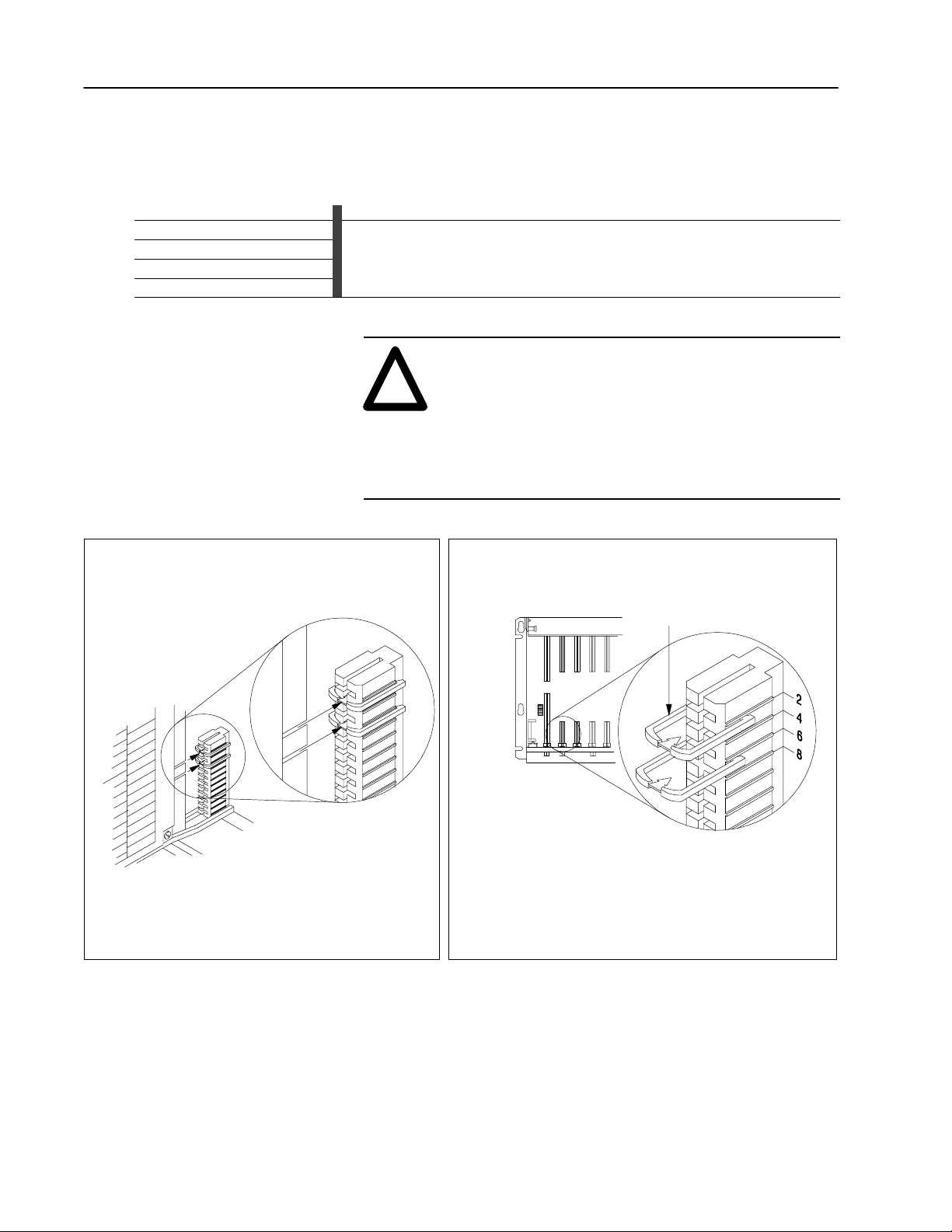
Key the Backplane Connector
The CFM module is slotted in two places on the rear edge of
the circuit board. These slots are intended to mate with the
plastic keying bands supplied with the I/O chassis.
any 8
.
or
Place the CFM module in any
module group w
16bit or block transfer module.
any 8
,
.
no restr
ons
ATTENTION: Observe the following precautions
when inserting or removing keys:
!
• insert or remove keys with your fingers
• make sure that key placement is correct
Incorrect keying or the use of a tool can result in
damage to the backplane connector and possible
system faults.
Position the keying bands in the backplane connectors to
correspond to the key slots on the CFM module.
I/O chassis
keying bands
CFM module
Publication
I/O chassis
backplane connector
17716.5.99 - December 1995
Place the keying bands:
between 2 and 4
between 6 and 8
You can change the position of these bands if subsequent system design
and rewiring makes insertion of a different type of module necessary.
19808
Page 25
2–7Install the CFM Module
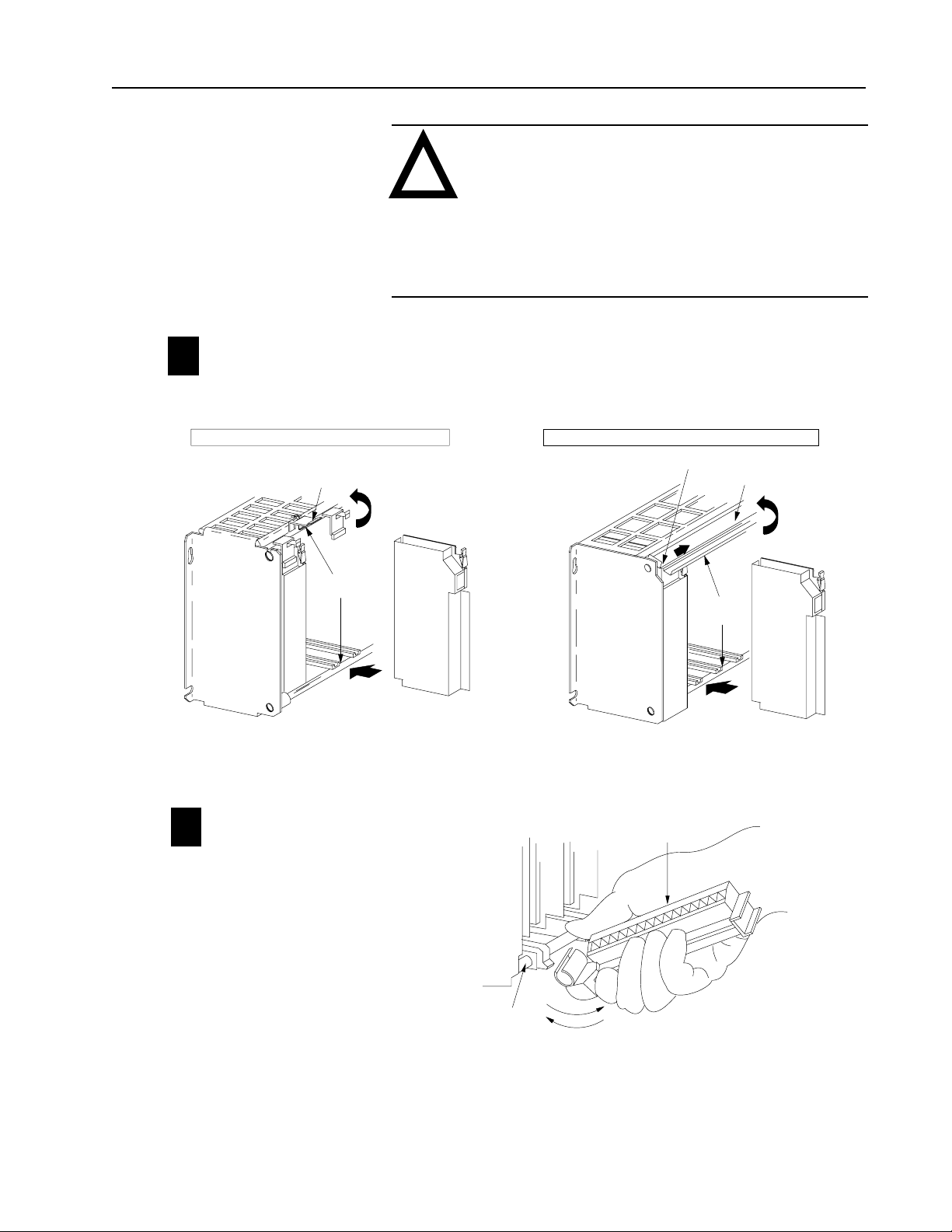
Install the CFM Module
Place the module in the card guides on the top and bottom of the slot
11
that guide the CFM module into position.
Important: Apply firm even pressure on the module to seat it into
its backplane connector.
1771A1B, A2B, A3B, A3B1, A4B I/O chassis 1771A1B, A2B, A3B1, A4B Series B I/O chassis
locking
card guides
tab
ATTENTION:Remove power from the 1771 I/O
chassis backplane before you install the CFM module.
!
Failure to remove power from the backplane
could cause:
•injury
•equipment damage due to unexpected operation
•degradation of performance
locking bar pin
locking bar
card guides
Snap the chassis latch over
the top of the module to secure it.
Attach the wiring arm (1771WN) to the horizontal
12
bar at the bottom of the I/O chassis.
The wiring arm pivots upward and connects with
the module so you can install or remove the
module without disconnecting the wires.
CFM module
CFM module
Swing the chassis locking bar down into place to secure
the modules. Make sure the locking pins engage.
wiring arm
1771WN
remove
horizontal bar
install
At power-up, the active and fault indicators are on. An initial
module self-check occurs. If there is no fault, the fault indicator
turns off. See page6–1 for information on interpreting the status
indicators.
19809
17643
Publication
17716.5.99 - December 1995
Page 26
2–8 Install the CFM Module
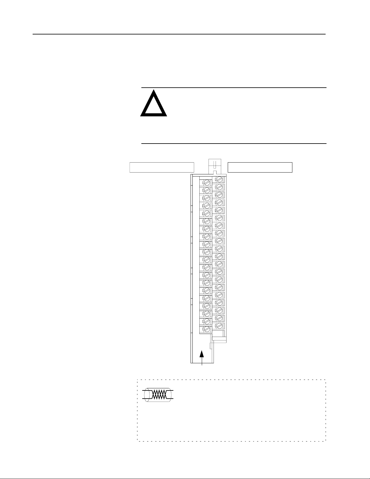
Make Connections to the Field Wiring Arm
DC source #1 @ 12mA RET (- proximity pickup)
DC source #2 @ 12mA RET (- proximity pickup)
Customer V DC #1 RET (Outputs 0 & 1 RET)
Customer V DC #2 RET (Outputs 2 & 3 RET)
Connect your I/O devices to the 40-terminal field wiring arm
(cat. no. 1771-WN) shipped with the CFM module. Use the wiring
examples on pages 2–9 and 2–10 for additional assistance on
connecting your devices.
ATTENTION:Remove power to all I/O devices
before you connect them to the wiring arm. Failure to
!
remove power from your I/O devices could cause:
•injury
•damage to module circuitry
•equipment damage due to unexpected operation
Even Numbered T
erminals 240
not used
not used
G0 RET
G1 RET
F0 (500mV)
F0 Input
F1 (500mV)
F1 Input
F2 (500mV)
F2 Input
F3 (500mV)
F3 Input
G2 RET
G3 RET
Output 0
Output 2
2
4
6
8
10
12
14
16
18
20
22
24
26
28
30
32
34
36
38
40
Odd Numbered T
1
Chassis GND
3
+5V dc RET
5
G0
7
G1
9
F0 (TTL)
11
F0 RET
13
F1 (TTL)
15
F1 RET
17
+24V DC source #1 @ 12mA
19
+24V DC source #2 @ 12mA
21
F2 (TTL)
23
F2 RET
25
F3 (TTL)
27
F3 RET
29
G2
31
G3
33
Customer V DC #1 (5 to 40V)
35
Output 1
37
Customer V DC #2 (5 to 40V)
39
Output 3
erminals 139
Publication
17716.5.99 - December 1995
1771WN
(See applicable codes and laws.)
actual wiring runs in this direction
The sensor cable must be shielded. The shield:
•must extend the length of the cable, but be connected only at the
1771 I/O chassis
•must extend up to the point of termination
Important:The shield should extend to the termination point,
exposing just enough cable to adequately terminate the
inner conductors. Use heat shrink or another suitable
insulation where the wire exits the cable jacket.
10689I
Page 27
2–9Install the CFM Module
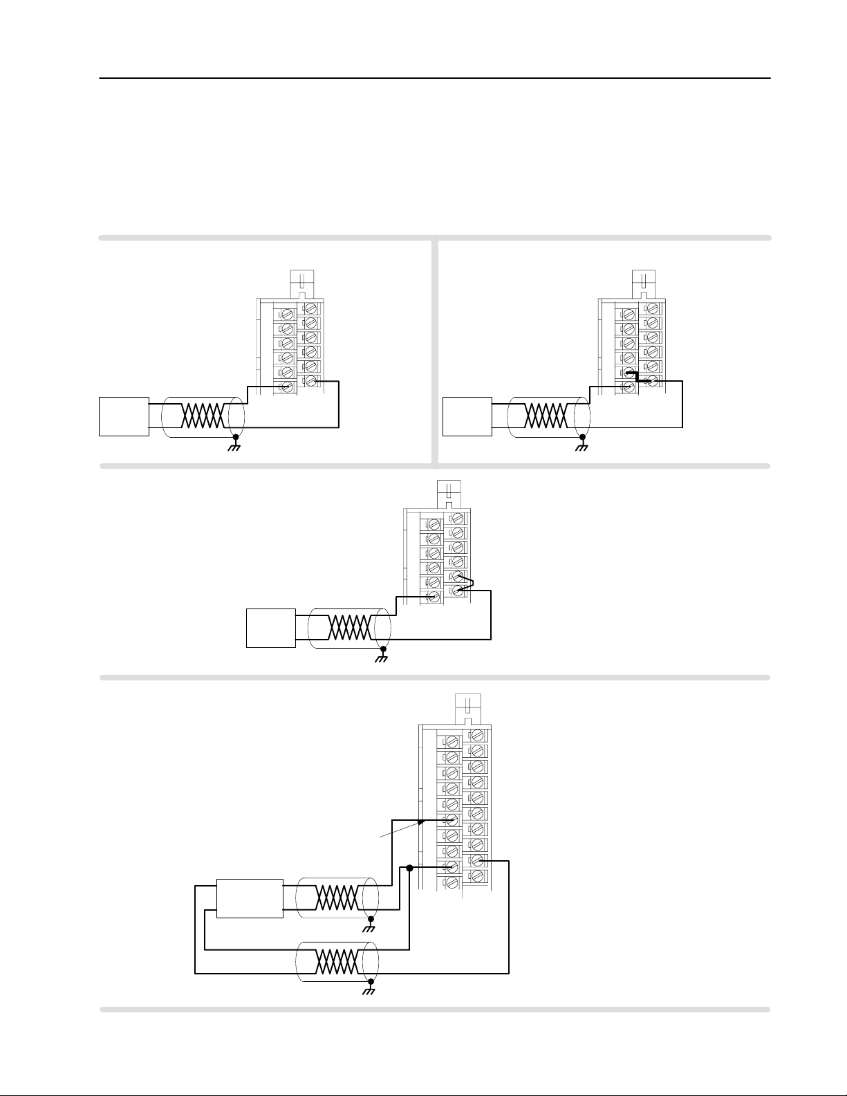
Wiring Examples
These wiring diagrams represent wiring for a flowmeter input (F0),
a gate input (G0) and an output (O0). See the wiring arm diagram
on page2–8 for the terminals used in wiring F1-F3, G1-G3
and O1-O3.
Standard Magnetic Pickup
50mV threshold (F0)
2
4
6
8
not used F0 (500mV)
+
Input
Device
-
F0 Input
10
12
➀ ➀
Standard TTL or Open Collector
1.3V threshold (F0)
Important: To use a channel in TTL, jumper
the appropriate TTL pin to the appropriate RET
To use Channel 0 in TTL, jumper pin 9 to pin 11.
Input
Device
1771WN
1
3
5
7
9
11
.
not
used F0 (500mV)
+
-
F0 (TTL)
F0 RET
F0 Input
not used
2
4
6
8
10
12
➀
Standard Magnetic Pickup
500mV threshold (F0)
Important: T
500mV sensor
pin to the appropriate RET. For
Channel 0, jumper pin 10 to pin 1
Input
Device
o use a channel for
+
-
1771WN
1
3
5
7
9
F0 (TTL)
11
F0 RET
, jumper the 500mV
F0 (500mV)
F0 Input
1771WN
2
1.
4
6
8
10
12
1
3
5
7
9
F0 (TTL)
11
F0 RET
not used
Standard Proximity
using CFM Module Source (F0)
+24V
DC source #1 @ 12mA RET (- proximity pickup)
+
-
Input
Device
1771WN
2
4
6
8
not used F0 (500mV)
F0 Input
+
10
12
14
16
18
20
1
3
5
7
9
F0 (TTL)
11
F0 RET not used
13
15
+24V DC source #1 @ 12mA to power a proximity transducer
17
19
not used
-
➀
➀
➀
For new installations, terminate the shields at
the chassis. While not recommended,
existing installations can continue to terminate
the shields at the return (RET) terminal.
Publication
17716.5.99 - December 1995
Page 28
2–10 Install the CFM Module
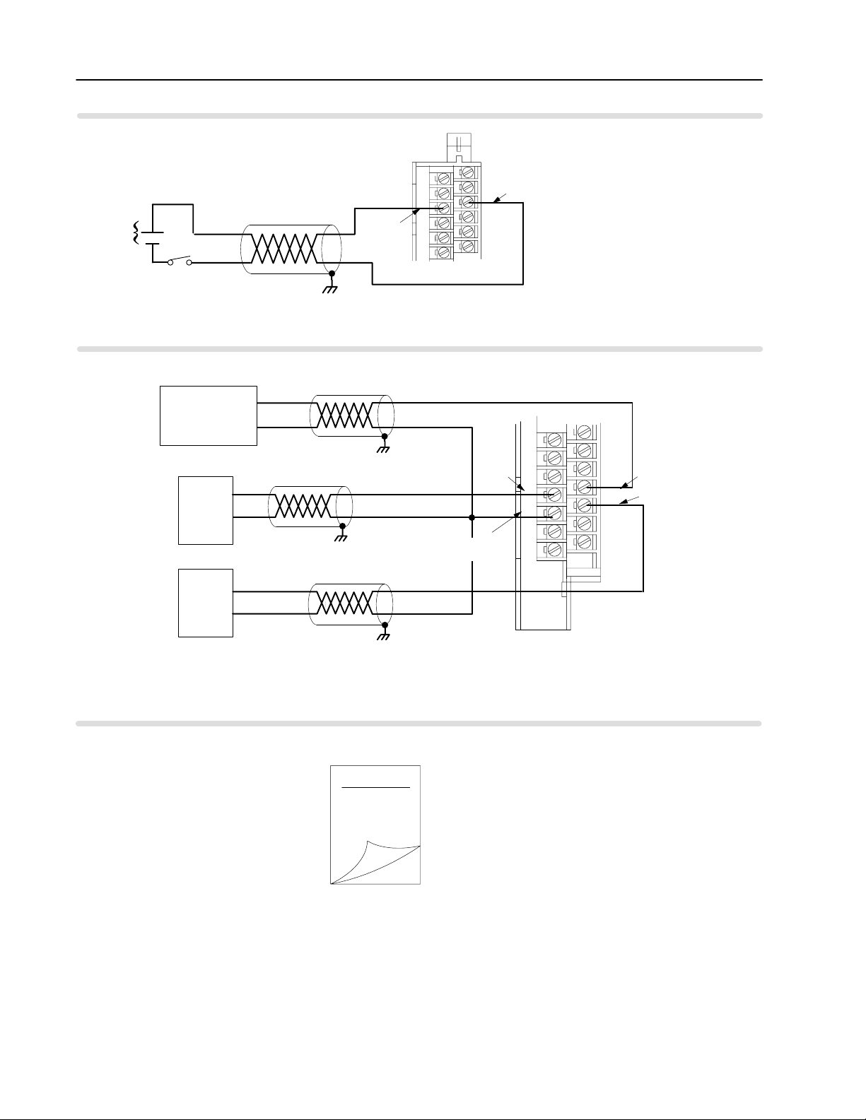
Standard Prover/Store Count (G0)
5-12V dc
OR
12-40V dc
-
+
S
1
Standard Output (O0)
External
Power Supply #1
540V dc @ 2A
+
LOAD 0
-
external device
➀
G0 RET
2
4
6
8
10
12
1771WN
1
3
5
7
9
11
G0
+
-
➀
Output 0
➀
Customer V DC #1 RET
(Outputs 0 & 1 RET)
28
30
32
34
36
38
40
27
29
31
Customer V DC #1 (5 to 40V)
33
Output 1
35
37
39
What's Next
LOAD 1
LOAD 1
+
-
➀
➀
For new installations, terminate the shields at
the chassis. While not recommended,
existing installations can continue to terminate
the shields at the return (RET) terminal.
3
Edit Your
Ladder Logic
Program
1771WN
Publication
17716.5.99 - December 1995
Page 29

Chapter
Edit Your Ladder Logic
Program
3
What This Chapter Contains
Enter Block Transfer Instructions
To initiate communication between the CFM module and your
PLC processor, you must enter block transfer instructions into your
ladder logic program. Use this chapter to enter the necessary block
transfer instructions into your ladder logic program.
To edit your ladder logic you See page
Enter Block Transfer Instructions. . . . . . . . . . . . . . . . . . . . .
PLC2 Family Processors. . . . . . . . . . . . . . . . . . . . . . . . 3-2
PLC3 Family Processors. . . . . . . . . . . . . . . . . . . . . . . . 3-3
PLC5 Family Processors. . . . . . . . . . . . . . . . . . . . . . . . 3-4
PLC5/250 Processors. . . . . . . . . . . . . . . . . . . . . . . . . .
The CFM module communicates with the PLC processor through
bidirectional block transfers. This is the sequential operation of both
read and write block transfer instructions.
Before you configure the CFM module, you need to enter block
transfer instructions into your ladder logic. The following example
programs illustrate the minimum programming required for
communication to take place between the CFM module and a PLC
processor. These programs can be modified to suit your application
requirements.
3-1
3-5
Publication
17716.5.99 - December 1995
Page 30
3–2 Edit Your Ladder Logic Program
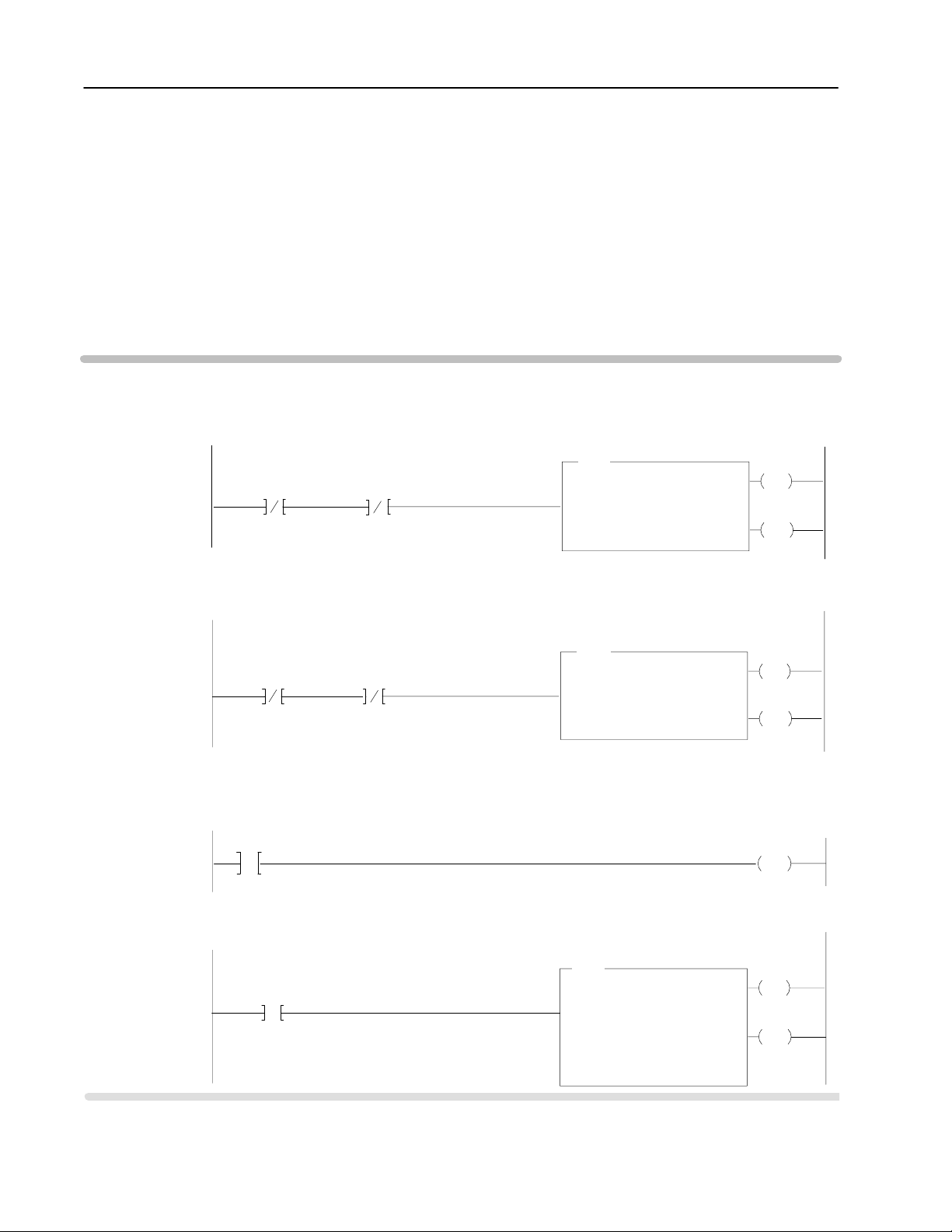
PLC2 Family Processor
Important: The CFM module functions with reduced performance
Use the following rungs to establish communication between the
CFM module and a PLC-2 processor.
in PLC-2 systems. Because the CFM module does not
support BCD and the PLC-2 processor is limited to
values of 4095 (12 bit binary), many values returned in
the BTR file may not provide meaningful data to the
PLC-2 processor.
PLC2 Processor
Program Example
Rung M:1
The CFM module is located in rack 1, I/O group 1, slot 0. The data address 030 must be among the first available timer/
address used for block transfer
counter
length other than 0 is desired, the BTR and BTW must not both be enabled in the same scan.
CFM BTR
Done Bit
111
07
Rung M:2
The CFM module is located in rack 1, I/O group 1, slot 0. The data address 031 must be among the first available timer/
address used for block transfer
counter
other than 0 is desired, the BTR and BTW must not both be enabled in the same scan.
CFM BTW
Done Bit
111
06
Rung M:3
This rung is used to place a zero between the first available timer counters used for all block transfers and those used
throughout the rest of the program.
UNUSED
must be = 0
032
G
0
Rung M:4
This rung uses the BTR done bit to trigger a FFM that moves the CFM status to a buffered data file. The program should
access all CFM data from the file starting at 401.
CFM BTR
Done Bit
111
07
CFM BTW
Enable Bit
CFM BTR
Enable Bit
. The default block length of 0 will return 41 words starting at address 301. If a block
CFM BTR Data Address
BTR
011
06
. The default length of 0 will send 60 words
011
07
BLOCK TRANSFER READ
Data Addr:
Module Addr:
Block Length:
File: 301-400
starting at address 201. If a block length
BTW
BLOCK TRANSFER WRITE
Data Addr:
Module Addr:
Block Length:
File: 201-300
FFM
FILE TO FILE MOVE
Counter Addr:
Position:
File Length:
File A:
File R:
Rate per Scan:
030
110
031
110
033
41
41
301-351
401451
41
00
00
must be = 0
011
EN
07
111
DN
07
011
EN
06
111
DN
06
UNUSED
032
PUT
0
033
EN
17
033
DN
15
Publication
17716.5.99 - December 1995
Page 31

3–3Edit Your Ladder Logic Program
PLC3 Family Processor
Block transfer instructions with the PLC-3 processor use a control
file and a data file. The block transfer control file contains the data
table section for module location, the address of the block transfer
data file and other related data. The block transfer data file stores
data that you want transferred to the module (when programming a
BTW) or from the module (when programming a BTR).
The programming terminal prompts you to create a control file when
a block transfer instruction is being programmed. The same block
transfer control file is used for both the read and write
instructions for your module. A different block transfer control
file is required for every module.
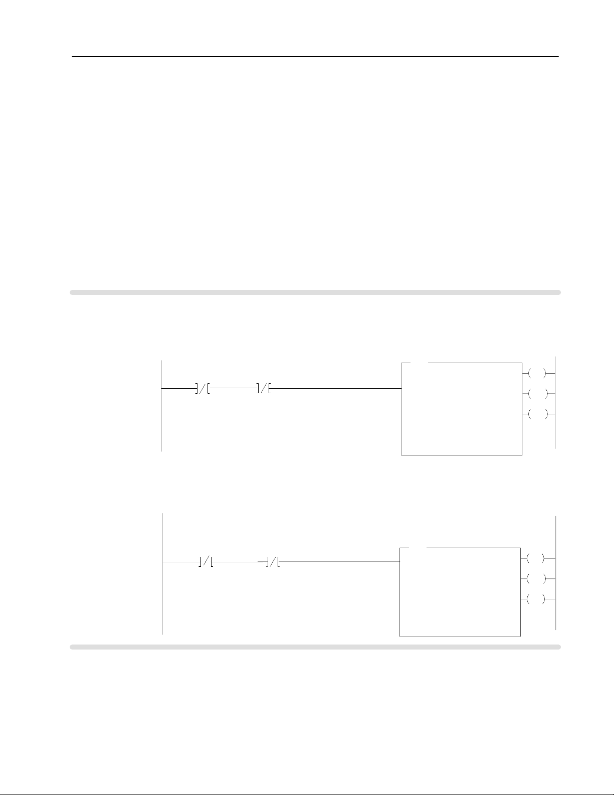
PLC3 Processor
Program Example
Rung M:0
The
CFM module is located in rack 3, I/O group 2, slot 1. The control file is a 10 word file starting at B17:0
by the BTR/BTW. The data obtained by the PLC3 processor is placed in memory starting at location N18:101, and with
the default length of 0, is 41 words long.
CFM BTR/BTW
Control Block
BTR
CFM BTR
Done Bit
B17:0
15
CFM BTR
Error Bit
B17:0
13
The CFM module is located in rack 3, I/O group 2, slot 1. The control file is a 10 word file starting at B17:0 that is shared
by the BTR/BTW. The data sent by the PLC3 processor to the CFM module is from PLC memory starting at N18:1, and
with the default length of 0, is 60 words long.
CFM BTW
Done Bit
B17:0
5
BLOCK TRANSFER READ
Rack
Group
Slot
Control
Data File
Length
CFM BTR
Error Bit
B17:0
U
13
CFM BTR/BTW
Control Block
BTW
BLOCK TRANSFER WRITE
Rack
Group
Slot
Control
Data
Length
N18:101
B17:0
B17:0
N18:1
that is shared
EN
3
2
DN
1
ER
0
EN
3
2
DN
1
ER
0
CFM BTW
Error Bit
B17:0
3
CFM BTW
Error Bit
B17:0
U
3
Publication
17716.5.99 - December 1995
Page 32

3–4 Edit Your Ladder Logic Program
PLC5 Family Processor
Block transfer instructions with the PLC-5 processor use a control
file and a data file. The block transfer control file contains the data
table section for module location, the address of the block transfer
data file and other related data. The block transfer data file stores
data that you want transferred to the module (when programming a
BTW) or from the module (when programming a BTR).
The programming terminal prompts you to create a control file when
a block transfer instruction is being programmed. A different block
transfer control file is used for the read and write instructions
for your module.
PLC5 Processor
Program Example
Rung 2:0
The CFM module is located in rack 0, I/O group 2, slot 1. The integer
compatible with all PLC5 family members. The data obtained by the PLC5 processor from the CFM module is placed in
memory starting at N22:101, and with the default length of 0, is 41 words long. The length can be any number between 0
and 41. In enhanced PLC5 processors
CFM BTR
Enable Bit
N22:200
CFM BTW
Enable Bit
N22:205
15
Rung 2:1
CFM module is located in rack 0, group 2, slot 1. The integer control file starts at N22:205, is a 5 words long and is compat
The
ible will all PLC5 family members. The data sent by the PLC5 processor to the CFM module starts at N22:1, and with the
default length of 0, is 60 words long. Valid BTW lengths: 0, 1, 2, 3, 4, 14, 24, 34, 44, 48, 52, 56 and 60.
In enhanced PLC5 processors
CFM BTR
Enable Bit
N22:200
CFM BTW
Enable Bit
N22:205
15
➀
, the block transfer data type may be used as a control file.
15
1
, the block transfer data type may be used as a control file.
15
control file starts at N22:200, is 5 words long and is
CFM BTR
BTR
BLOCK TRANSFER READ
Rack
Group
Slot
Control
Data File
Length
Continuous
BTW
BLOCK TRANSFER WRITE
Rack
Group
Slot
Control
Data File
Length
Continuous
Control File
CFM BTW
Control File
N22:200
N22:101
00
N22:205
N22:1
00
EN
2
DN
1
ER
0
N
EN
2
DN
1
ER
0
N
Publication
➀
Enhanced PLC5 processors include: PLC5/11, 5/20, 5/3x, 5/4x, and 5/6x.
17716.5.99 - December 1995
Page 33
3–5Edit Your Ladder Logic Program
PLC5/250 Processor
Block transfer instructions with the PLC-5/250 processor use a
control file and a data file. The block transfer control file contains
the data table section for module location, the address of the block
transfer data file and other related data. The block transfer data file
stores data that you want transferred to the module (when
programming a BTW) or from the module (when programming
a BTR).
The programming terminal will automatically select the control file
based on rack, group and module, and whether it is a read or write.
A different block transfer control file is used for the read and
write instructions for your module. A different block transfer
control file is required for every module.
PLC5/250 Processor
Program Example
Rung 1STEPO:1
The
CFM module is located in rack 14, I/O group 1, slot 0. The data
CFM module is placed in the data table starting at 2BTD5:101, and with the default length of 0, is 41 words long.
The length can be any number between 0 and 41.
CFM BTR
Enable Bit
BR141:0
EN
Rung 1STEPO:1
CFM module is located in rack 14, I/O group 1, slot 0. The data sent to the CFM module from the PLC5/250 processor
The
is from the data table starting at 2BTD5:1, and with a default length of 0, is 60 words long.
Valid BTW lengths: 0, 1, 2, 3, 4, 14, 24, 34, 44, 48, 52, 56 and 60.
CFM BTR
Enable Bit
BR141:0
EN
CFM BTW
Enable Bit
BW141:0
EN
CFM BTW
Enable Bit
BW141:0
EN
obtained by the PLC5/250 processor from the
CFM BTR
BTR
BLOCK TRANSFER READ
Rack
Group
Slot
Control Block
Data File
BT Length
Continuous
BT Timeout 4
BTW
BLOCK TRANSFER WRITE
Rack
Group
Slot
Control Block
Data File
BT Length
Continuous
BT Timeout 4
Control File
14
1
0
BR141:0
2BTD5:101
0
NO
CFM BTW
Control File
14
1
0
BW141:0
2BTD5:1
0
NO
EN
DN
ER
EN
DN
ER
Publication
17716.5.99 - December 1995
Page 34

3–6 Edit Your Ladder Logic Program
What's Next
4
Configure the
CFM Module
Publication
17716.5.99 - December 1995
Page 35

Chapter
Configure the CFM Module
4
What This Chapter Contains
Understand the CFM
Module's BTW Structure
Use this chapter to configure the CFM module.
To configure the CFM module See page
Understand the CFM Module's BTW Structure . . . . . . . . . . . . 4-1
BTW Configuration Block . . . . . . . . . . . . . . . . . . . . . . . . 4-2
Select the Mode(s) of Operation . . . . . . . . . . . . . . . . . . . . . . 4-8
Configure the CFM Module . . . . . . . . . . . . . . . . . . . . . . . . . 4-16
Using I/O Configuration Software . . . . . . . . . . . . . . . . . . . 4-16
Setting Bits in the BTW Configuration Block . . . . . . . . . . .
Important: You must edit your ladder logic as shown in chapter 3
before you can use this chapter to configure the BTW
configuration block.
Data is conditioned through a group of data table words that are
transferred from the PLC processor to the CFM module using a
BTW instruction. Now that you have entered BTW and BTR
instructions into your ladder logic, you are ready to enter data into
the BTW instruction. This data should conform to the input device
and specific application that you have chosen.
4-16
During normal operation, the processor transfers from 1 to 60 words
to the CFM module when you program a BTW instruction to the
CFM module’s address.
Important: You must program at least one BTW, with a word
length of 4, to get useful data back from the
CFM module.
For See page(s)
a general overview of the CFM module's BTW configuration block
detailed descriptions of each word in the BTW configuration block 4-3 through 4-7
4-2
Publication
17716.5.99 - December 1995
Page 36

4–2 Configure the CFM Module
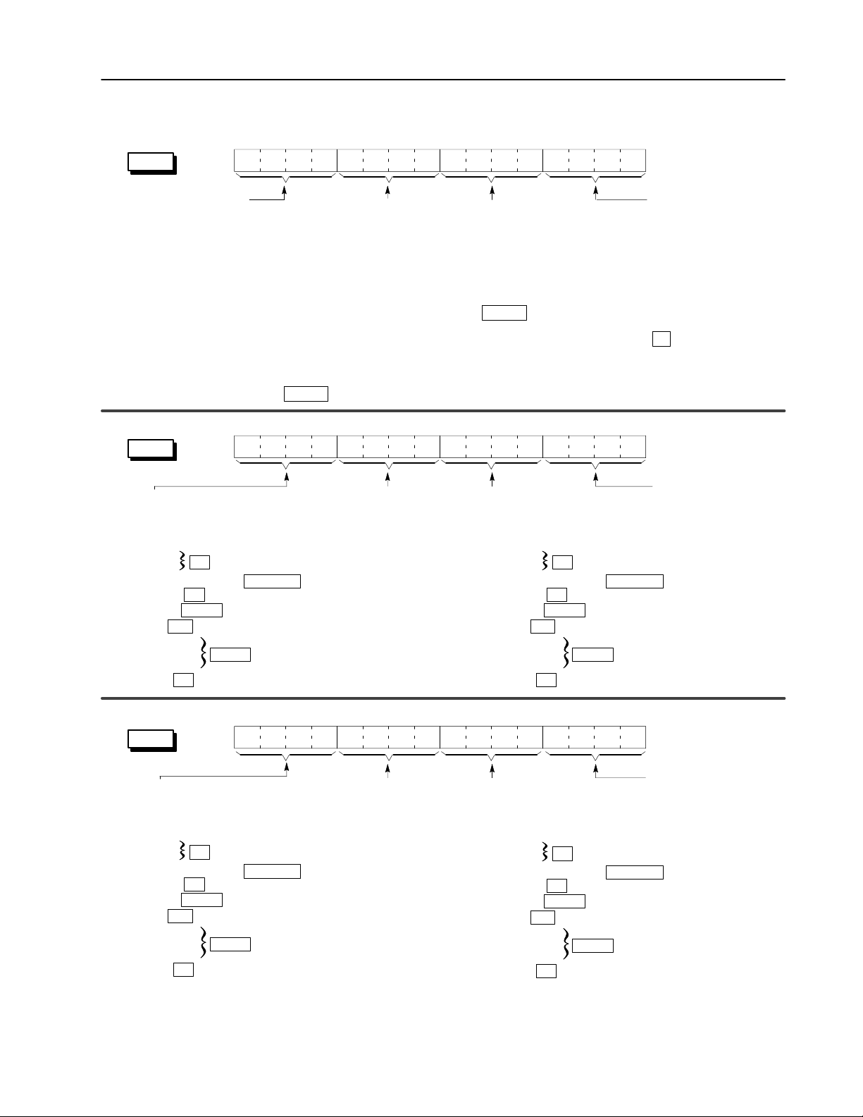
É
BTW Configuration Block
➀
Word(s)
1 Header Prover
2 Output 1 Trigger T
3 Output 3 Trigger T
4 Channel
5,
15, 25, 35
6, 16, 26, 36
7, 17, 27, 37
8, 18, 28, 38
9, 19, 29, 39
10, 20, 30, 40
1
1, 21, 31, 41
12, 22, 32, 42
13, 23, 33, 43
14, 24, 34, 44
45,
49, 53, 57
46, 50, 54, 58
47, 51, 55, 59
48, 52, 56, 60
➀
Valid
BTW lengths are: 0, 1, 2, 3, 4, 14, 24, 34, 44, 48, 52, 56, 60.
➁
ALL
numeric values are in binary
➂
When scaling is used, all outputs are still controlled by the actual value not the scaled value.
15 14 13 12 11 10 09 08 07 06 05 04 03 02 01 00
Block
Output
1 and Output 0 T
Output
3 and Output 2 T
Input
Channel Operating Mode
3
Input
Channel Configuration
Channel 0 (words 514) Channel 1 (words 1524) Channel 2 (words 2534) Channel 3 (words 3544)
Frequency
in
10ths
Bandwidth
Limit
Sampling
Termination
4 x
High Hz
Prover
Type
Acceleration Alarm V
Frequency Scaler Multiplier
Rollover Value Most Significant Digit (0999 x 10,000)
Rollover Value Least Significant Digit (09,999)
Number of Pulses to T
Output
Output 0 (words 4548) Output 1 (words 4952) Output 2 (words 5356) Output 3 (words 5760)
Output ON value Most Significant Digit (0999 x 10,000)
Output ON value Least Significant Digit (09,999)
Output OFF value Most Significant Digit (0999 x 10,000)
Output OFF value Least Significant Digit (09,999)
.
➁
Bit
ID & Resets
Run Initialize
rigger & Select
ie Output 1 to Channel
rigger & Select
ie Output 3 to Channel
Channel 2
Debounce
Filtering
ÉÉ
Minimum Frequency Sampling T
erminate Sampling
Highest Allowable Frequency
alue (what rate to trigger on)
➂
T
otal Scaler Multiplier
T
otal Scaler Divisor
➂
➂
Configuration
Overflow Reset
Output 0 T
Output 2 T
rigger T
rigger T
Channel 1
Acceleration Calculation Time
ime
Frequency Scaler Divisor
T
otal Reset
ie Output 0 to Channel
ie Output 2 to Channel
Channel 0
➂
word #
Publication
BTW Word Description Key
Bits
15 14 13 12 11 10 09 08 07 06 05 04 03 02 01 00
Description of what these bits are used for.
Mode(s) that use these bits.
17716.5.99 - December 1995
Mode
abbreviations:
Totalizer = T
Nonresettable T
otalizer = NR
T
Highresolution Frequency = HR
Direction Sensor = DS
Page 37
word 1
4–3Configure the CFM Module
BTW Word Descriptions
15 14 13 12 11 10 09 08 07 06 05 04 03 02 01 00
0010
Header must be 0010.
Identifies the module as a
CFM module.
15 14 13 12 11 10 09 08 07 06 05 04 03 02 01 00
word 2
Output 1 Trigger selects what
channel characteristic output 1
is triggered ON or OFF by placing
the shown hex values in these bits:
0 = Force OFF
1 = Frequency
2 = % of Fullscale Frequency
3 = Acceleration
4 = Total Value
5 = Direction
DS
all
T,
all
T,
NR
T
NRT, HR
6 = Overflow
7 = Prover Running
T
, NR
T
8 = Prover Range
F = Force ON
all
Prover Run Initialize initializes the
channel for prover inputs on the Gate.
Also resets Store Count Value
(BTR words 13 & 14). Only occurs on a
change in bit state from a 0 to a 1.
This bit should remain ON (= 1) until the
prover is done or until the prover run is
aborted.
b08 = Counter 0 b10 = Counter 2
b09 = Counter 1 b11 = Counter 3
If this bit is OFF (= 0), a low to high transition
of the Gate will store the current count in
Store Count Value (BTR words 13 & 14).
T, NRT
Tie Output 1 to Channel ties
output 1 to operate according to
the state of a specific channel.
b08 = Counter 0 b10 = Counter 2
b09 = Counter 1 b11 = Counter 3
Output 0 Trigger selects what
channel characteristic output 0
is triggered ON or OFF by placing
the shown hex values in these bits:
0 = Force OFF
1 = Frequency
2 = % of Fullscale Frequency
3 = Acceleration
4 = Total Value
5 = Direction
6 = Overflow
7 = Prover Running
8 = Prover Range
F = Force ON
Overflow Reset resets the
overflow status of the module for
the appropriate counter on a 0 to 1
transition. Only occurs on a
change in bit state from a 0 to a 1.
b04 = Counter 0 b06 = Counter 2
b05 = Counter 1 b07 = Counter 3
T, NRT
all
T
T
, NR
, NRT, HR
T
DS
all
T
, NR
T
all
Total Reset resets the
total count for the
appropriate counter on a 0
to 1 transition.
Only occurs on a change
in bit state from a 0 to a 1.
b00 = Counter 0
b01 = Counter 1
b02 = Counter 2
b03 = Counter 3
T
Tie Output 0 to Channel
ties output 0 to operate
according to the state
of a specific channel.
b00 = Counter 0
b01 = Counter 1
b02 = Counter 2
b03 = Counter 3
15 14 13 12 11 10 09 08 07 06 05 04 03 02 01 00
word 3
Output 3 Trigger selects what
channel characteristic output 3
is triggered ON or OFF by placing
the shown hex values in these bits:
0 = Force OFF
1 = Frequency
2 = % of Fullscale Frequency
3 = Acceleration
4 = Total Value
5 = Direction
DS
all
T
all
, NR
T
, NRT, HR
T
6 = Overflow
7 = Prover Running
T
, NR
T
8 = Prover Range
F = Force ON
all
Tie Output 3 to Channel ties
output 3 to operate according to
the state of a specific channel.
b08 = Counter 0 b10 = Counter 2
b09 = Counter 1 b11 = Counter 3
Output 2 Trigger selects what
channel characteristic output 2
is triggered ON or OFF by placing
the shown hex values in these bits:
0 = Force OFF
1 = Frequency
2 = % of Fullscale Frequency
3 = Acceleration
4 = Total Value
5 = Direction
DS
T
all
all
, NR
T
, NRT, HR
T
6 = Overflow
7 = Prover Running
T
, NR
T
8 = Prover Range
F = Force ON
all
Publication
Tie Output 2 to Channel
ties output 2 to operate
according to the state of
a specific channel.
b00 = Counter 0
b01 = Counter 1
b02 = Counter 2
b03 = Counter 3
17716.5.99 - December 1995
Page 38

4–4 Configure the CFM Module
15 14 13 12 11 10 09 08 07 06 05 04 03 02 01 00
word 4
Operating Mode for Channel 3
Select a mode of operation on a per
channel basis by placing the shown
hex values in the proper bits:
word 5 (channel 0)
word 5 (channel 0)
word 15 (channel 1)
word 15 (channel 1)
word 25 (channel 2)
word 25 (channel 2)
word 35 (channel 3)
word 35 (channel 3)
Frequency in 10ths allows you
to select the precision of the
frequency returned in the BTR.
If set, the frequency is returned
with the LSD being in tenths,
while if 0, the LSD is in ones.
0
= frequency returned as 100, 123
1 = frequency returned as 100, 123.2
HR
15 14 13 12 11 10 09 08 07 06 05 04 03 02 01 00
Operating Mode for Channel 2
0 = unused channel
1 = Totalizer 3 = Highresolution Frequency (channels 0 & 1 or 2 & 3)
2 = Nonresettable Totalizer 4 = Direction Sensor (channels 0 & 1 or 2 & 3)
➀
These modes are selected only via channel 0 or channel 2.
➁
If using both channels (0 & 1 and 2 & 3) for this mode, you cannot set sampling time for both = 4ms.
Sampling Termination
if set, enables the input
sampling to be terminated
on either a time base only
(BTW 6) or a set number
of input pulses (BTW 7)
depending on which
condition arises first.
HR
Bandwidth Limit if set, limits the minimum
frequency the CFM module is capable of reading
to 1/Minimum Frequency Sampling Time.
When 1: the worst case response time of the
module is decreased to approximately
2 x Minimum Frequency Sampling Time.
When 0: frequency range = 1Hz 100kHz
(worst case response time can be 2s at
extremely low frequencies)
0 = full frequency range (1Hz 100kHz)
1 = minimum frequency (1/Minimum Frequency Sampling Time)
all
Operating Mode for Channel 1
Debounce Filtering
debounces the Gate
input for a period of 1s.
The first low to high transition
of the gate will cause the
CFM module to take
appropriate action (no other
transitions will be seen for 1s).
0 = OFF / 1 = ON
T, NRT
Prover Type selects the type
of prover being used
(unidirectional or bidirectional):
0 = unidirectional (1 run, 2 switches)
1 = bidirectional (4 switch run)
T, NRT
4 x High Hertz if set, the Highest Allowable
Frequency entry is multiplied by 4 to enable
entries > 32,767.
For example, to get a 100,000 peak allowable
frequency, you set this bit and enter 25,000 in the
word containing the Highest Allowable Frequency
(BTW 8, 18, 28 or 38).
all
Operating Mode for Channel 0
➀
➀➁
Acceleration Calculation Time
calculates acceleration every Nth
frequency sample.
0 = acceleration rolling average over 5
samples
1750 = number of frequency samples
(BTW 9 Acceleration Alarm Value must
0 0).
For example, if you place a value of 7
here, the CFM module:
a. stores the 1st frequency calculation
b. subtracts this calculation from the
8th frequency sample
c. divides this remainder by the time
between samples and places the
result in BTR 11, 20, 29 or 38
d. stores the 8th frequency sample
and waits for the 15th sample
all
word 6 (channel 0)
word 16 (channel 1)
15 14 13 12 11 10 09 08 07 06 05 04 03 02 01 00
word 26 (channel 2)
word 36 (channel 3)
Minimum Frequency Sampling Time specifies the minimum time the
CFM module spends to determine frequency (unless Number of Pulses to
Terminate Sampling is enabled in Highresolution Frequency mode, which may
allow the the input channel to end sampling earlier than the specified minimum).
Important: In Direction Sensor, this time is used to determine the maximum
sample time and the minimum frequency returned and does not
actually determine the time period for frequency sampling.
all
Publication
17716.5.99 - December 1995
RANGE: 4ms 1000ms (0 3 = DEFAULT)
DEFAULTS: HR, DS = 4ms / T, NRT = 100ms
The maximum sampling time is:
< 2s if the Bandwidth Limit is not enabled and
a signal < 1 Hz is applied (sample time [
Minimum Frequency Sampling Time + 1/frequency input)
< 2 x the Minimum Frequency Sampling Time
if
Bandwidth Limit is enabled and a very low input signal
frequency is applied (sample time [
Minimum Frequency Sampling Time + 1/frequency input)
Page 39

4–5Configure the CFM Module
word 7 (channel 0)
word 17 (channel 1)
word 27 (channel 2)
word 37 (channel 3)
word 8 (channel 0)
word 18 (channel 1)
word 28 (channel 2)
word 38 (channel 3)
word 9 (channel 0)
word 19 (channel 1)
word 29 (channel 2)
word 39 (channel 3)
15 14 13 12 11 10 09 08 07 06 05 04 03 02 01 00
Number of Pulses to Terminate Sampling applied when Sampling Termination (bit 13 of word 5, 15, 25 or 35)
is set. Causes the sampling to cease when the specified number of input pulses are received or the
Minimum Frequency Sampling Time is exceeded, which ever occurs first. RANGE: 032,767
Highresolution Frequency
15 14 13 12 11 10 09 08 07 06 05 04 03 02 01 00
Highest Allowable Frequency the highest frequency allowed on the channel. When the specified frequency is
exceeded, the channel's overspeed alarm will activate. Also used to calculate Percent of Full Scale (BTR word 6,15,24,33).
RANGE: 0 32,767 DEFAULT: 0 (=120,000)
Used with the 4 x High Hertz (bit 12 of word 5, 15, 25, or 35) to have an effective range of 0120,000.
all
15 14 13 12 11 10 09 08 07 06 05 04 03 02 01 00
word 10 (channel 0)
word 20 (channel 1)
word 30 (channel 2)
word 40 (channel 3)
Acceleration Alarm Value determines at what acceleration values (Hz/s) the BTR alarm bits are activated.
The alarm bits occur when the absolute value of the acceleration exceeds the Acceleration Alarm Value.
This word also determines whether acceleration is calculated. A value of 0 deactivates all acceleration calculations.
RANGE: 0 32,767 (0 disables)
all
15 14 13 12 11 10 09 08 07 06 05 04 03 02 01 00
Frequency Scaler➀ Multiplier the frequency value
returned in the BTR is multiplied by the specified value.
RANGE: 0255 DEFAULT: 1
all
Frequency Scaler Divisor the frequency value
returned in the BTR is divided by the specified value.
RANGE: 0255 DEFAULT: 1
all
Important: The Frequency Multiplier must be ≤ the Frequency Divisor.
Example:
If
Frequency Divisor = 50, Frequency Multiplier = 6 and frequency at the input = 75 Hz,
the scaled value returned will be 6/50(75) = 9
➀
When
scaling is used, all outputs are still controlled by the actual value (in example, 75Hz) not the scaled value (in example, 9).
Publication
17716.5.99 - December 1995
Page 40

4–6 Configure the CFM Module
word 11 (channel 0)
word 21 (channel 1)
word 31 (channel 2)
word 41 (channel 3)
word 12 (channel 0)
word 22 (channel 1)
word 32 (channel 2)
word 42 (channel 3)
word 13 (channel 0)
word 23 (channel 1)
word 33 (channel 2)
word 43 (channel 3)
15 14 13 12 11 10 09 08 07 06 05 04 03 02 01 00
Total Scaler➀ Multiplier the total
value returned in the BTR is multiplied by
the specified value.
RANGE: 032,767 DEFAULT: 1
Important: The Total Scaler Multiplier must be ≤ Total Scaler Divisor
See Total Scaler Divisor.
T, NRT
➀
When scaling is used, all outputs are still controlled by the actual value not the scaled value.
15 14 13 12 11 10 09 08 07 06 05 04 03 02 01 00
Total Scaler➀ Divisor the total value
returned in the BTR is divided by the
specified value.
RANGE: 0 32,767 DEFAULT: 1
Important: The Total Scaler Multiplier must be ≤ Total Scaler Divisor.
See Total Scaler Multiplier.
T, NRT
➀
When scaling is used, all outputs are still controlled by the actual value not the scaled value.
15 14 13 12 11 10 09 08 07 06 05 04 03 02 01 00
MSD - ranges from
0999 x 10,000
.
word 14 (channel 0)
word 24 (channel 1)
word 34 (channel 2)
word 44 (channel 3)
Rollover Value the count value that
the totalizer will reset or rollover to 0 at.
T, NRT
RANGE: 0 9,999,999
DEFAULT: 0 (which is rollover of 10,000,000)
Important: The Rollover Value must be ≥ (actual frequency x 10ms).
If you are using the prover function, the expected Prover
Total Count Value (BTR words 13/14, 22/23, 31/32, or
40/41) must be < Rollover Value.
15 14 13 12 11 10 09 08 07 06 05 04 03 02 01 00
LSD ranges from 09,999
Publication
17716.5.99 - December 1995
Page 41

4–7Configure the CFM Module
word 45 (channel 0)
word 49 (channel 1)
15 14 13 12 11 10 09 08 07 06 05 04 03 02 01 00
word 53 (channel 2)
word 57 (channel 3)
Output ON Value the value at which the output turns ON.
word 46 (channel 0)
word 50 (channel 1)
word 54 (channel 2)
word 58 (channel 3)
15 14 13 12 11 10 09 08 07 06 05 04 03 02 01 00
ON
and OFF output values can be triggered by:
Frequency
Percent of Fullscale
Acceleration
Total
Direction
Overflow
Prover Range of Operation
(use LSD word 46, 50, 54, 58
Prover Running
unidirectional prover: ON from 25
bidirectional prover: ON from 23 and 45
= 0120,000
= 032,767 (use LSD word 46, 50, 54, 58
= -32,768 32,767 (use LSD word 46, 50, 54, 58
= 09,999,999
= 0 (stopped), 1 (clockwise), 2 (counterclockwise)
(use LSD word 46, 50, 54, 58
= 0 (output follows
= 0 Output is ON when the prover is actually counting.
Overflow
= 05 ON and OFF values must be different
only)
only)
bit, BTR words 4 & 5)
Important: When any type of scaling is used (frequency or total),
outputs are always triggered by the actual value not the
scaled value. Outputs triggered by Total turn ON in < 100µs
and turn OFF in < 100µs. All other ON and OFF times
are < 1ms.
only)
only)
MSD ranges from
0999 x 10,000
all
LSD ranges from 09,999
Prover
Range of Operation (value of bits in hex)
prover not selected
0 =
1 =
prover is not running, but
prover running past the 1st switch in forward leg
2 =
3 =
prover is done with forward leg, returning at this time
midrun value (bidirectional only)
4 =
prover is returning on 2nd leg (bidirectional only)
5 =
prover is done with run (BTR word 13/14 contains prover count value)
On Value
output on while >=
12,000 15,000
output on when >=
and < Off
or <
Off
active
On
On
:
Of
f V
alue
12,00015,000
word 47 (channel 0)
word 51 (channel 1)
word 55 (channel 2)
word 59 (channel 3)
word 48 (channel 0)
word 52 (channel 1)
word 56 (channel 2)
word 60 (channel 3)
15 14 13 12 11 10 09 08 07 06 05 04 03 02 01 00
MSD ranges from
0999 x 10,000
Output OFF Value the value at which the output turns OFF. all
LSD ranges from 09,999
15 14 13 12 11 10 09 08 07 06 05 04 03 02 01 00
Publication
17716.5.99 - December 1995
Page 42
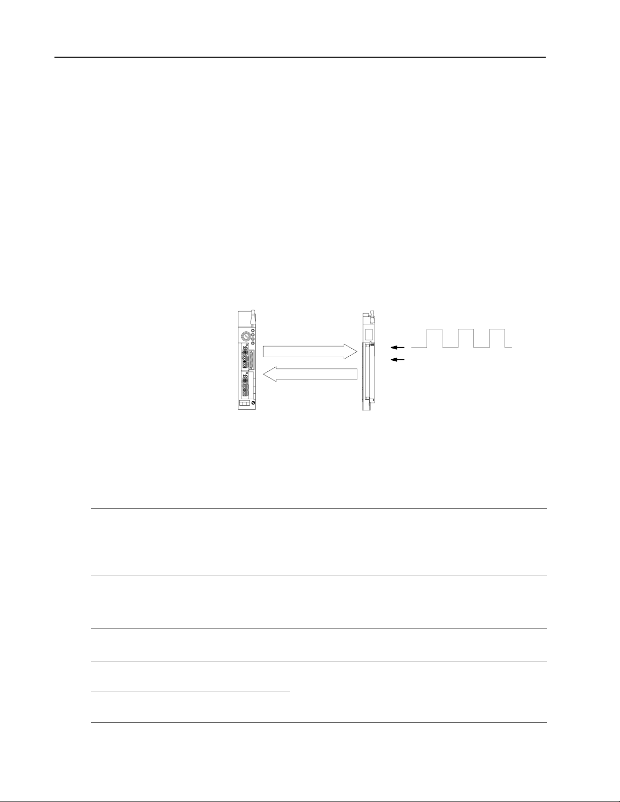
4–8 Configure the CFM Module
Total Multipli
Select the Mode(s) of Operation
Use Totalizer mode if you:
• need counting (totalization) capabilities
• can measure frequency over a fixed
sampling period (4ms1s)
• need a frequency value
• need prover capabilities
• need count storage capabilities
• also want to calculate acceleration
Use Nonresettable Totalizer mode
if you want to use the features of the
Totalizer mode with NO BTW reset
capabilities.
Typical applications:
• measuring ingredients in a
batch process
• oil pipeline terminals (prover)
You select the mode(s) of operation and configure each input channel
to accept input signals from your input device(s).
Totalizer and Nonresettable Totalizer Modes
These modes measure incoming pulses over a user-specified time
interval (4-1000ms). In either of these modes, the CFM module
calculates:
• rate of input (0-100,000Hz)
• total count (0-9,999,999)
• acceleration value
• optional prover value
• optional store count value (current count value)
PLC processor
BTW
BTR
configuration
status and input data
1771CFM
F0
G0
prover/store
input
device
Counting
In these modes, the CFM module counts pulses based on values you
enter in the BTW configuration block. You can specify these values:
Value BTW word # Use to
specify the value at which the CFM module will rollover to zero and begin
counting again. DEFAULT: 0 = 10,000,000 RANGE: 09,999,999
Rollover
Overflow Reset 1 (bits 0407)
Total Reset
(Totalizer mode only)
Total Scaler Multiplier 11, 21, 31, 41
Total Scaler Divisor 12, 22, 32, 42
13/14, 23/24, 33/34, 43/44
1 (bits 0003)
Important: Every time a rollover occurs, the CFM module changes the
resets the overflow status of the CFM module for the appropriate input
channel. When this bit is set, the CFM module will reset the Overflow
Status (BTR words 4 & 5, bits 02 & 10). Overflow Status toggles between
0101 every time a rollover occurs. Overflow Status is not affected by
Total Reset.
reset the total count to zero. This occurs on a change in bit state from a
0 to a 1. This value does not effect the Overflow Status
(BTR word 4 & 5, bits 2 & 10).
scale the returned total count to actual engineering units.
For each value RANGE: 032,767 DEFAULT: 1
The scaled value can not be used to trigger any outputs (outputs triggered
by count are triggered by actual count).
state of the Overflow Status bit. (toggles between 0 1 every
time an overflow occurs). The Overflow Status can also be
manually reset in the BTW (word 1, bits 0003).
er must be < Total Divisor.
Publication
17716.5.99 - December 1995
Page 43

4–9Configure the CFM Module
Bandwidth Limit
(word 5, bit 14)
set (ON)?
N
and
no pulses are
received after the
sampling time expires,
the frequency is
calculated up to 2s after
the initial pulse and will
measure frequencies as
low as 1Hz.
Value BTW word # Use to
Minimum Frequency Sampling Time 6, 16, 26, 36
Bandwidth Limit
Acceleration Calculation Time 5, 15, 25, 35 (bits 0009)
Acceleration Alarm 9, 19, 29, 39
Frequency Multiplier/Divisor 10, 20, 30, 40
Highest Allowable Frequency 8, 18, 28, 38
and
no pulses are received
Y
within one more sample
time, the frequency will
then be calculated. The
minimum frequency is then
1/Minimum Frequency
Sampling Time
maximum time period is
2 x Minimum Frequency
Sampling Time.
and the
Frequency
Sampling
In the Totalizer and Nonresettable Totalizer modes, the CFM module
begins a frequency sample arbitrarily and ends the sampling within
1ms after the sampling time has expired and one pulse has been
detected. You can use Bandwidth Limit to exert control over the
CFM module’s frequency sampling.
In these modes, the CFM module calculates frequency based on
these values:
specify the minimum time the CFM module will spend collecting
pulses to determine a frequency. The time period begins arbitrarily,
not on a leading edge of a pulse.
Frequency is calculated after a pulse occurs and the time has
expired. The total time is measured and used with the sampled
counts to determine a frequency. This frequency value is in BTR
word 7/8, 16/17, 25/26 or 34/35.
As the actual frequency decreases, the actual sample time will
increase (for frequencies < 1Hz, it can take as long as 2s to
calculate the frequency). See Bandwidth Limit.
control the maximum time the CFM module spends calculating a
frequency and the minimum frequency that can be read by the
CFM module.
5, 15, 25, 35 (bit 14)
If ON: limits the maximum time period to 2 x Minimum Frequency
Sampling Time and minimum frequency to 1/Minimum Frequency
Sampling Time.
If OFF: maximum time period is 2s, minimum frequency is 1Hz.
specify the number of frequency samples the CFM module will
spend to calculate the acceleration value. The default value (0) will
calculate a rolling average of the previous five samples.
Since the frequency sample time may vary, so does the actual
acceleration calculation time.
determine the acceleration value that, if exceeded, will activate the
BTR Acceleration Alarm (word 4 & 5, bits 00 & 08).
RANGE: 032,767
The CFM module will not calculate an acceleration if
this acceleration value is zero.
scale the returned frequency and acceleration to actual engineering
units. Frequency Multiplier must be < Frequency Divisor.
For each value RANGE: 0255 DEFAULT: 0 (= 1
no scaling)
The scaled frequency/acceleration values can not be used to
trigger any outputs (outputs triggered by frequency/ acceleration
are triggered by actual frequency/acceleration).
specify the highest frequency value allowed on the input channel.
When this value is exceeded, the input channel's overspeed alarm
will activate.
This value is also used in calculating Percent of Full Scale
(BTR, word 6, 15, 24 or 33).
Publication
17716.5.99 - December 1995
Page 44

4–10 Configure the CFM Module
Value BTW word # Use to
Prover Run Initialize
Debounce Filtering 5, 15, 25, 35 (bit 10)
1 (bits 0811)
Storing Count Value
In the Totalizer and Nonresettable Totalizer modes, the CFM module
stores the current count based on these values:
initialize an input channel for prover inputs on the gate or to store current
count value (if prover not used).
If OFF (=0) CFM module stores the current count every time there is a
low to high transition at the appropriate gate input terminal. As each value
is stored, the Prover Status (BTR words 4 & 5, bits 46) will be updated to
indicate a new value. Prover Status toggles between 6 and 7 (hex) as
each new gate transition occurs:
6 = prover not active & new store count A
7 = prover not active & new store count B
If ON (= 1) the CFM module resets to 0 any previously stored count
contained in Store Count Value
(BTR words 13 & 14, 22 & 23, 31 & 32, or 40 & 41) and then waits for the
proper number of gate transitions to occur
(2 for unidirectional and 4 for bidirectional).
,
As the gate transitions occur
updated accordingly, dependent upon the current state of the prover:
0 = prover not selected
1 = prover running, but not active
2 = prover running past the 1st switch in forward leg
3 = prover is done with forward leg, returning at this time
midrun value (bidirectional only)
4 = prover is returning on 2nd leg (bidirectional only)
5 = prover is done with run (BTR word 13/14 contains prover count value)
The prover run is aborted and the Prover Status is set to 0 any time
Prover Run Initialize is set to 0. The time between gate transitions must be
long enough to allow the PLC processor to perform a BTR and get the
updated stored value.
debounce gate input for a period of 1s.
If ON: CFM module takes appropriate action at the first low to high
transition (at the gate input) and ignores all other gate transitions for 1s.
If OFF: CFM module takes appropriate action at every low to high
transition (at the gate input).
Prover Status (BTR words 4 & 5, bits 46) is
Publication
17716.5.99 - December 1995
Page 45
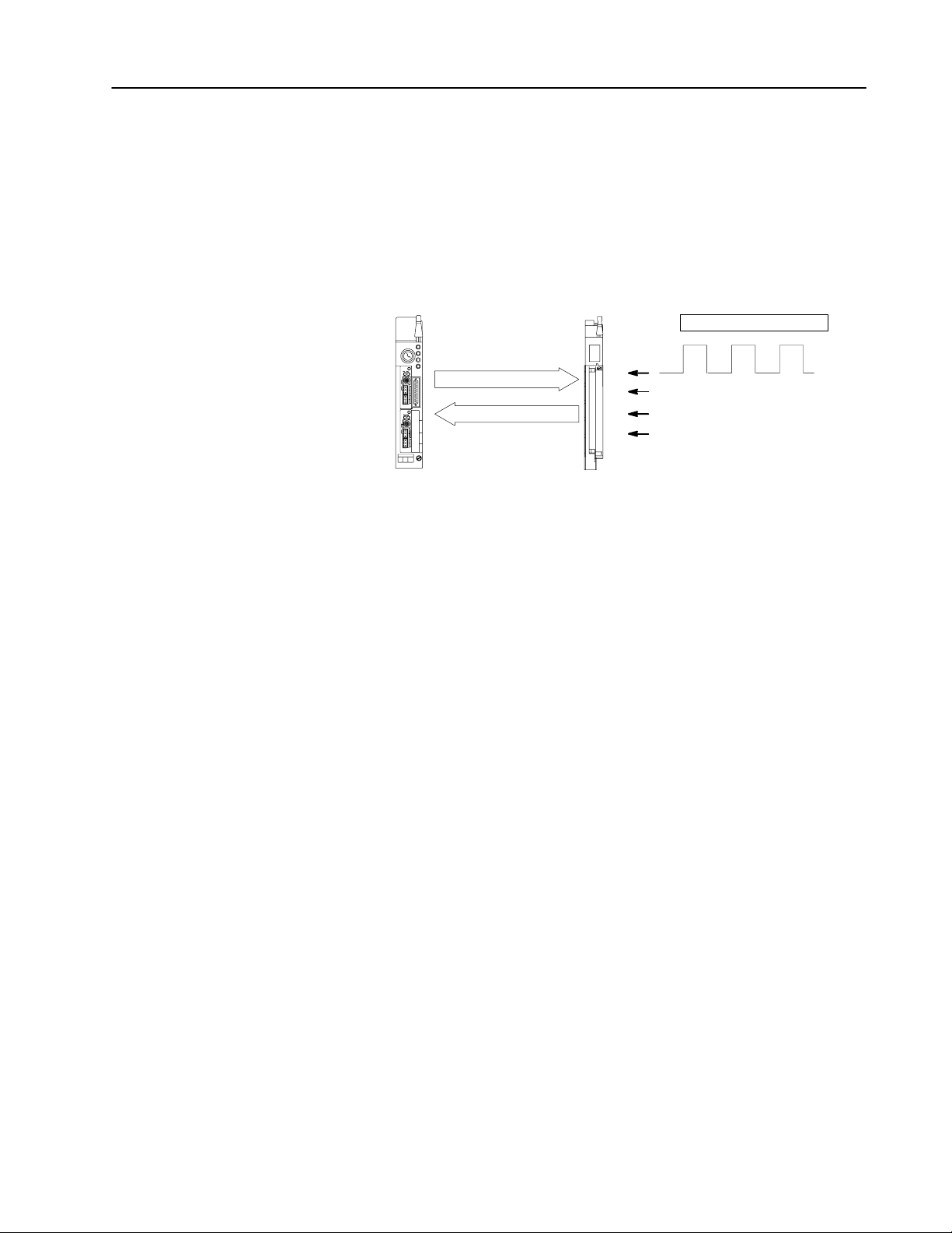
Highresolution Frequency Mode
4–11Configure the CFM Module
Use this mode if you:
• need accurate frequency value
(see page A-1 for frequency accuracy)
• need fastest possible sample
update time across large
frequency range
• want to calculate acceleration
• need to measure frequency in 10ths of Hz
(0.1Hz)
Typical application:
turbine generators
This mode measures incoming pulses over a user-specified time
interval (4-1000ms) or over a user-specified number of input
signal pulses. In this mode, the CFM module calculates:
• rate of input (0-100,000Hz)
• acceleration value
PLC processor
BTW
configuration
BTR
status and input data
Frequency
Sampling
In the High-resolution Frequency mode, frequency sampling begins
on the leading edge of the first pulse to occur and ends on the next
pulse to occur after the sampling time has expired or after the
user-specified number of pulses has occurred. In this mode, the CFM
module calculates frequency based on values you enter in the BTW
configuration block.
1771CFM
F0
G0
F1
G1
uses channels 0&1 or 2&3
not used
not used
not used
input
device
Publication
17716.5.99 - December 1995
Page 46

4–12 Configure the CFM Module
Value BTW word # Use to
Minimum Frequency Sampling Time
➀
Sampling Termination 5, 15, 25, 35 (bit 13)
Bandwidth Limit 5, 15, 25, 35 (bit 14)
Acceleration Calculation Time 5, 15, 25, 35 (bits 0009)
Acceleration Alarm 9, 19, 29, 39
Number of Pulses to Terminate Sampling 7, 17, 27, 37
Highest Allowable Frequency 8, 18, 28, 38
Frequency Scaler Multiplier/Divisor 10, 20, 30, 40
➀
If you are setting this value for both channels (0 & 1 and 2 & 3), the Minimum Frequency Sampling Time for both cannot = 4ms
(one can = 4ms and the other can = 5ms, but both cannot = 4ms).
You can specify these values:
specify the minimum time the CFM module will spend collecting
6, 16, 26, 36
pulses to determine a frequency. The sample begins on the
leading edge of a pulse.
terminate the sampling on either a time base or a set number of
pulses, depending on which occurs first.
control the maximum time the CFM module spends calculating
a frequency and the minimum frequency that can be read by
the CFM module.
specify the number of frequency samples the CFM module will
spend to calculate the acceleration value. The default value (0)
will calculate a rolling average of the previous five samples.
Since the actual frequency sample time can vary, so does the
Acceleration Calculation Time.
determine the acceleration value that, if exceeded, will activate
the BTR Acceleration Alarm (word 4 & 5, bits 00 & 08).
RANGE: 032,767
The CFM module will not calculate an acceleration if this
acceleration value is zero.
terminate the sampling when the specified number of input
pulses are received.
specify the highest frequency value expected on the input
channel. When this value is exceeded, the input channel's
overspeed alarm will activate.
This value is also used in calculating Percent of Full Scale
(BTR word 6, 15, 24 or 33).
scale the returned frequency and acceleration to actual
engineering units.
Frequency Multiplier must be < Frequency Divisor.
For each value RANGE: 1255 DEFAULT: 1
The scaled frequency/acceleration value can not be used to
trigger any outputs (outputs triggered by frequency/acceleration
are triggered by actual frequency/acceleration).
Publication
17716.5.99 - December 1995
Page 47
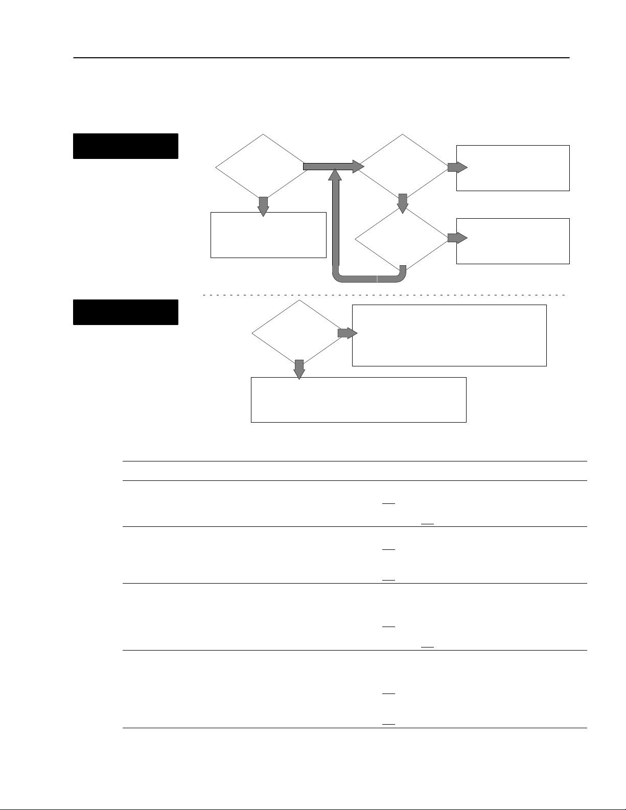
Sampling Termination
(for input channel 0)
Sampling Termination
(word 5, bit 13)
N
CFM module calculates
frequency based on Minimum
Frequency Sampling Time
(word 6)
➀
The
module calculates a new frequency on the next pulse to occur after the
expiration of the specified time; therefore, the actual period will be longer than
specified in word 6. Upon calculation of the frequency
Use these diagrams to understand how you use Sampling
Termination and Bandwidth Limit to exert even more control over
the CFM module’s frequency sampling.
Y
The CFM module calculates
frequency on the next pulse
to occur after time expires.
Y
CFM module calculates
frequency immediately after
the specified number of
pulses occur.
set (ON)?
➀
, the outputs are updated.
Y
Minimum Frequency
Sampling Time
(word 6)
expired?
N
Number of Pulses
to Terminate Sampling
(word 7)
received?
N
4–13Configure the CFM Module
1
Bandwidth
Limit
(for input channel 0)
Sampling
termination
OFF (= 0) OFF (= 0) 1Hz
OFF (= 0) ON (= 1) 1/Minimum Frequency Calculation Time
ON (= 1) OFF (= 0) 1Hz
ON (= 1) ON (= 1) 1/Minimum Frequency Calculation Time
➀
The terminate conditions assume a start pulse has been received.
➁
The next sample begins at the first pulse that occurs after a valid sample is taken.
Bandwidth
limit
The minimum frequency the CFM module can detect
Y
Bandwidth Limit
(word 5, bit 14)
set (ON)?
is 1/Minimum Frequency Calculation Time.
When set, the CFM module will spend no more than
(2 x Minimum Frequency Sampling Time) to
determine a new frequency value.
N
The CFM module can distinguish frequencies as low as 1Hz.
At low frequencies (< Minimum Frequency Sampling Time),
the CFM module may take as long as 2s to calculate a new
frequency value.
Terminate Conditions
Minimum frequency distinguishable
➀
Frequency sample taken➁ and outputs updated when
Minimum Frequency Sampling Time elapsed
at least one pulse received
and
OR
2s elapsed and
Minimum Frequency Sampling Time elapsed
and at least one pulse received
OR
(2 x Minimum Frequency Sampling Time) elapsed
no pulse received
and
Number of Pulses to Terminate Sampling received
OR
Minimum Frequency Sampling Time elapsed
at least one pulse received
and
OR
2s elapsed and
Number of Pulses to Terminate Sampling received
OR
Minimum Frequency Sampling Time elapsed
at least one pulse received
and
OR
(2 x Minimum Frequency Sampling Time) elapsed
no pulse received
and
no pulse received
no pulse received
Publication
17716.5.99 - December 1995
Page 48

4–14 Configure the CFM Module
Direction Sensor Mode
Use this mode if you want to determine
shaft direction.
Typical Applications:
• turbine generators
• pumps
Use this mode to measure shaft direction. In this mode, the
CFM module calculates:
• rate of input (0-100,000Hz)
• acceleration value
• direction of shaft
PLC processor
BTW
configuration
BTR
status and input data
F0 & F1 used in TTL
Frequency
Sampling
In this mode, frequency samples are taken every revolution by
measuring A and B:
1771CFM
F0
G0
F1
G1
uses channels 0&1 or 2&3
not used
not used
clockwise
counterclockwise
A
= the time between F0 input channel pulses (determines shaft frequency)
B
= the time between F0 and F1 input channel pulses (determines shaft direction)
If Direction is
B < 1/2 A
B > 1/2 A
F0
B
shaft
A
F0
shaft
A
B
F1
notch
shaft
F1
clockwise
counterclockwise
low true signal
proximity sensors at
F0 and F1 should be
60 to 120° apart
low true signal
sensor F1
F0
Both sensors cannot be low at
the same time.
F1
B
A
Publication
17716.5.99 - December 1995
Page 49

Value BTW word # Use to
determine
Minimum Frequency Sampling Time
6, 16, 26, 36
sample times are based on the time between F0 or F2 pulses.
If Bandwidth Limit is OFF (= 0), Minimum Frequency Sampling
Time is not used.
control the maximum time the CFM module spends calculating
a frequency and the minimum frequency that can be read by
the CFM module.
If ON: limits the maximum time period to
2 x Minimum Frequency Sampling Time and minimum
Bandwidth Limit 5, 15, 25, 35 (bit 14)
frequency to 1/Minimum Frequency Sampling Time.
Frequencies < 1/Minimum Frequency Sampling Time
are reported as stopped.
If OFF: maximum time period is 3s, minimum frequency is 1Hz
and direction can be sensed to 1/3Hz.
Minimum Frequency Sampling Time is not used.
specify the number of frequency samples the CFM module will
spend to calculate the acceleration value. The default value (0)
Acceleration Calculation Time 5, 15, 25, 35 (bits 0009)
will calculate a rolling average of the previous
five samples. Since the actual frequency sample time may
vary, so does the Acceleration Calculation Time.
determine the acceleration value that, if exceeded, will activate
the BTR Acceleration Alarm (word 4 & 5, bits 00 & 08).
Acceleration Alarm 9, 19, 29, 39
RANGE: 032,767
The CFM module will not calculate an acceleration if
this acceleration value is zero.
4–15Configure the CFM Module
the minimum frequency and maximum sample time. All
Frequency Multiplier/Divisor 10, 20, 30, 40
Highest Allowable Frequency 8, 18, 28, 38
scale the returned frequency and acceleration to actual
engineering units.
Frequency Multiplier must be < Frequency Divisor.
For each value RANGE: 1255 DEFAULT: 1
The scaled frequency/acceleration value can not be used to
trigger any outputs (outputs triggered by frequency/acceleration
are triggered by actual frequency/acceleration).
specify the highest frequency value allowed on the input
channel. When this value is exceeded, the input channel's
overspeed alarm will activate.
Publication
17716.5.99 - December 1995
Page 50

4–16 Configure the CFM Module
Configure the Module
To configure the CFM module, you set the appropriate bits in the
BTW instruction. You do this:
•through I/O Configuration software if you are using a PLC-5
family processor (see PLC-5 Programming Software I/O
Configuration Manual, publication 6200-6.4.12, for supported
processors)
or
•by editing bits at the address of the BTW instruction
Using I/O Configuration Software
To configure the CFM module using I/O Configuration software, you
enter the appropriate information on the CFM module edit screens.
Use these documents to help you use I/O Configuration software:
Using
I/O
Configuration
Software
E
PLC5
Programming
Software
I/O
Configuration
Software
What's Next
publication 62006.4.12
Setting Bits in the BTW Configuration Block
If you are not using the I/O configuration utility, edit the data file
addresses in the BTW instruction to match your particular
application. Use the word descriptions on pages 4–3 through 4–7
to help you edit the bits that apply to your application(s).
5
Interpret
Module Status
and Input Data
Publication
17716.5.99 - December 1995
Page 51

Chapter
Interpret Module Status and
Input Data
5
What This Chapter Contains
Understand the CFM
Module's BTR Structure
Use this chapter to interpret module status and input data from the
CFM module.
To interpret module status and input data See page
Understand The CFM Module's BTR Structure . . . . . . . . . . . .
BTR Word Assignments . . . . . . . . . . . . . . . . . . . . . . . . . 5-2
Example PLC5 processor Status and Input Data . . . . .
Your PLC processor gets data from the CFM module using BTR
instructions in your ladder logic program. The CFM module
transfers up to 41 words to the PLC processor’s data table file.
The words contain module status and input data from each channel.
You should program a block transfer read length of zero (0). When a
BTR of 0 is programmed, the CFM module will determine the
correct number of words (41) to return.
For See page(s)
a general overview of the BTW configuration block 5-2
detailed descriptions of each word in the BTW configuration block 5-3 through 5-5
an example of a data table print out 5-6
5-1
5-6
Publication
17716.5.99 - December 1995
Page 52

5–2 Interpret Module Status and Input Data
É
BTR Word Assignments
Word(s)
1
14 13 12 11 10 09 08 07 06 05 04 03 02 01 00
15
Block
ID & Resets
Header
Bit
Output Status & Diagnostics
2
3 Channel
Output Status
3
Channel 2
Mode
Indication
Channel 1
Channel 1 Status
Prover
4
Status
Overrange
Alarm
Overflow
Status
Overspeed
Alarm
Acceleration
Alarm
Channel 3 Status
Prover
5
Status
Overrange
Alarm
Channel 0 (words 614) Channel 1 (words 1523) Channel 2 (words 2432) Channel 3 (words 3341)
6,
15, 24, 33
7, 16, 25, 34 Frequency (0120 ) MSD
8, 17, 26, 35
9, 18, 27, 36
10, 19, 28, 37
1
1, 20, 29, 38
12, 21, 30, 39
13, 22, 31, 40
14, 23, 32, 41
not used
Overflow
Status
Overspeed
Alarm
Input
Acceleration
Alarm
É
Channel Data
Percent of Full Scale (Rate % of High RPM value)
Frequency (0999) LSD
T
otal MSD (0999)
T
otal LSD (09,999)
Acceleration (rate of change of frequency)
Prover T
Prover T
otal Count V
otal Count V
alue or Store Count V
alue or Store Count Value LSD (09,999)
* Numeric values are in binary except for
Diagnostics
Error
Channel 0 Status
Prover Status
Overrange
Channel 2 Status
Prover Status
alue MSD (0999)
(word 2, bits 0007)
Overrange
Words & Diagnostics
Channel 0
Alarm
Alarm
Overflow
Status
Overflow
Status
Direction
*
Overspeed
Alarm
Overspeed
Alarm
Powerup
bit
Acceleration
Alarm
Acceleration
Alarm
Publication
15 14 13 12 11 10 09 08 07 06 05 04 03 02 01 00
word #
17716.5.99 - December 1995
not used
BTR Word Description Key
Bits
Description of what these bits are used for.
Mode(s) that use these bits.
Mode
abbreviations:
Totalizer = T
Nonresettable T
otalizer = NR
T
Highresolution Frequency = HR
Direction Sensor = DS
Page 53

word 1
Header must be 0010.
word 2
BTR Word Descriptions
15 14 13 12 11 10 09 08 07 06 05 04 03 02 01 00
0010
VALUES: 1= no or invalid BTW
15 14 13 12 11 10 09 08 07 06 05 04 03 02 01 00
5–3Interpret Module Status and Input Data
Powerup Bit indicates if
a valid BTW has occurred
since powerup or since
last switched from
Program to Run mode.
0 = yes
word 3
Mode Indication for Channel 3
Indicates mode of operation that
channel is currently running in.
word 4
Output Status reflects current
operating state of outputs.
b12 = Output 0 b13 = Output 1
VALUES:
0 = OFF
1 = ON
Error Words & Diagnostics displays
invalid BTW word # (060 BCD).
99 = invalid BTW length.
b14 = Output 2 b15 = Output 3
15 14 13 12 11 10 09 08 07 06 05 04 03 02 01 00
Mode Indication for Channel 0
Mode Indication for Channel 2
Mode Indication for Channel 1
0 = unused channel
1 = Totalizer 3 = Highresolution Frequency (channels 0 & 1 or 2 & 3)
2 = Nonresettable Totalizer 4 = Direction Sensor (channels 0 & 1 or 2 & 3)
Channel 0Channel 1
15 14 13 12 11 10 09 08 07 06 05 04 03 02 01 00
Prover
Status
Overflow
Overrange
Alarm
Status
Acceleration
Overspeed
Alarm
Alarm
Prover
Status
Overrange
Alarm
Overflow
Status
Acceleration
Overspeed
Alarm
Alarm
word 5
15 14 13 12 11 10 09 08 07 06 05 04 03 02 01 00
Channel 2Channel 3
Overrange Alarm
on if the frequency is > than
100kHz (frequencies > 100kHz
may not be accurately returned).
all
Overflow Status
toggles between 0101 every time a
rollover occurs. This bit is reset by
BTW word 1 (bits 0407).
T
, NR
T
Prover Status indicates the current state of prover (value of bits in hex).
Overspeed Alarm
on if frequency is >
Highest Allowable Frequency
(BTW word 8, 18, 28, 38).
T,
NR
T
Acceleration Alarm
on if |acceleration value| is >
Acceleration Alarm Value
(BTW word 9, 19, 29, 39).
allall
0 = prover not selected 4 = prover is returning on reverse leg (bidirectional only)
1 = prover not running, but active 5 = prover is done with run (BTR word 13/14 contains prover count value)
2 = prover running past the 1st switch in forward leg 6 = prover not active & new store count A
3 = prover is done with forward leg and returning at this time 7 = prover not active & new store count B
intermediate value returned (bidirectional only)
if prover not active,
these bits toggle 6767 every
high transition of the gate
Publication
17716.5.99 - December 1995
Page 54

5–4 Interpret Module Status and Input Data
word 5 (Channel 0)
word 6 (Channel 0)
word 15 (Channel 1)
word 15 (Channel 1)
word 25 (Channel 2)
word 24 (Channel 2)
word 35 (Channel 3)
word 33 (Channel 3)
word 7 (channel 0)
word 16 (channel 1)
word 25 (channel 2)
word 34 (channel 3)
15 14 13 12 11 10 09 08 07 06 05 04 03 02 01 00
Percent of Full Scale (Rate % of High RPM value)
the calculated frequency scaled by the Highest
Allowable Frequency (BTW 8, 18, 28, 38) and then
0 = 0%
32, 767 ≥ 100%
% = BTR word 6,15,24,33 / 32,767
expressed as a number from 0 to 32,767.
T, NRT, HR
For example, if:
BTW word 5 bit 12, 4 x Highest Hertz = 1 (ON)
bit 15, Frequency in 10ths = 0 (OFF)
Percent Full Scale (BTR 6) = 32,767
BTW word 8 Highest Allowable Frequency = 21,750Hz
BTR word 7 = 1
BTR word 8 = 1410
15 14 13 12 11 10 09 08 07 06 05 04 03 02 01 00
Frequency = 11,410Hz
Percent Full Scale (BTR 6) = 4,297
Frequency indicates the calculated frequency.
RANGE: 0120,000
If
Frequency in 10ths (word 5,15,25,35 bit 15) is:
not set MSD range = 012 x 10,000 / LSD range = 09,999
Example: If word 7 = 6 and word 8 = 532, Frequency = 6(10,000) + 532 = 60,532
set MSD range = 0120 x 1,000 / LSD range = 09,999 x 0.10
Example: If word 7 = 6 and word 8 = 532, Frequency = 6(1,000) + 532(0.10) = 6,053.2
(21,750 x 4) / 11,410
MSD
range depends on
status of
Frequency in 10ths
(BTW word 5,15,25,35 bit 15)
and mode of operation
all
HR
word 8 (channel 0)
word 17 (channel 1)
word 26 (channel 2)
word 35 (channel 3)
LSD range depends
on status of BTW
Frequency in 10ths bit
15 14 13 12 11 10 09 08 07 06 05 04 03 02 01 00
Publication
17716.5.99 - December 1995
Page 55

5–5Interpret Module Status and Input Data
word 9 (channel 0)
word 18 (channel 1)
word 27 (channel 2)
word 36 (channel 3)
word 10 (channel 0)
word 10 (channel 0)
word 19 (channel 1)
word 19 (channel 1)
word 28 (channel 2)
word 28 (channel 2)
word 37 (channel 3)
word 37 (channel 3)
word 11 (channel 0)
word 20 (channel 1)
word 29 (channel 2)
word 38 (channel 3)
15 14 13 12 11 10 09 08 07 06 05 04 03 02 01 00
Total the total counts registered by the input channel.
Example: If word 9 = 93 and word 10 = 1234, Total = 93(10,000) + 1,234 = 931,234
RANGE: 0 9,999,999
T, NRT
15 14 13 12 11 10 09 08 07 06 05 04 03 02 01 00
15 14 13 12 11 10 09 08 07 06 05 04 03 02 01 00
Acceleration (rate of change of frequency) the calculated acceleration value (Hz/s).
RANGE: -32,767 to 32,767
all
MSD
ranges from
0999 x 10,000
LSD ranges from 09,999
word 12 (channel 0)
word 21 (channel 1)
15 14 13 12 11 10 09 08 07 06 05 04 03 02 01 00
word 30 (channel 2)
word 39 (channel 3)
If Bandwidth Limit is:
ON orientation and frequency can be sensed to
1/Minimum Frequency Sampling Time. Frequencies <
1/Minimum Frequency Sampling Time are reported as stopped.
OFF direction can be sensed to 0.33Hz and frequencies < 1Hz
are reported as 0.
word 13 (channel 0)
word 22 (channel 1)
15 14 13 12 11 10 09 08 07 06 05 04 03 02 01 00
word 31 (channel 2)
word 40 (channel 3)
Prover Total Count Value or Store Count Value when Prover Run Initialize (BTW 1, bits 811) is:
enabled the value returned is the prover count (intermediate and final run values).
not enabled the value returned is the last count stored when the Gate input went low to high. These words
are reset to 0 when Prover Run Initialize (BTW 1, bits 811) changes in bit state from a 0 to a 1.
T, NRT
word 14 (channel 0)
word 23 (channel 1)
word 32 (channel 2)
word 41 (channel 3)
15 14 13 12 11 10 09 08 07 06 05 04 03 02 01 00
Direction indicates the current detected direction 0 = stopped
of the input pulses in Direction Sensor modes. 1 = clockwise
DS
2 = counterclockwise
MSD
ranges from
0999 x 10,000
LSD ranges from 09,999
Publication
17716.5.99 - December 1995
Page 56

5–6 Interpret Module Status and Input Data
Example
reading data from the CFM module
In this example, the CFM module:
•
has a constant input frequency of 729Hz fed to all channels
•
has input channels configured as follows:
CH 0 CH 1 CH 2 & 3
Operating Mode
Minimum Frequency Sampling Time 50ms 250ms 10ms
Highest Allowable Frequency 25000 10000 50000
Acceleration Alarm Value 3500
Acceleration Calculation Time 10 (every 10 frequency samples)
Rollover Value 360000
Frequency Scaler Multiplier
Divisor
Frequency in 10ths 0.1Hz
Bandwidth Limit 1/sample time
Sampling Termination time or 200 counts
The
following data table is a printout from the PLC5 processor program example (page
(160) and BTR words (101141), in binary
1771CFM
Data T
Address 0 1 2 3 4 5 6 7 8 9
N22:0 0 8192 0 0 801 10 50 0 25000 3500
N22:10 1572 0 0 36 0 0 250 0 10000 0
N22:20 0 0 0 0 0 -4096 10 200 12500 0
N22:30 0 0 0 0 0 0 0 0 0 0
N22:40 0 0 0 0 0 0 0 0 0 0
N22:50 0 0 0 0 0 0 0 0 0 0
N22:60 0 0 0 0 0 0 0 0 0 0
N22:70 0 0 0 0 0 0 0 0 0 0
N22:80 0 0 0 0 0 0 0 0 0 0
N22:90 0 0 0 0 0 0 0 0 0 0
N22:100 0 8192 0 801 4 0 969 0 123 26
N22:110 2789 0 0 0 0 2392 0 730 62 2853
N22:120 0 0 0 0 477 0 7289 0 0 0
N22:130 0 0 0 0 0 0 0 0 0 0
N22:140 0 0 0 0 0 0 0 0 0 0
Sample PLC5 Program
able Report
Totalizer Nonresettable Totalizer Highresolution Frequency
6
36
3-4
). This printout shows the BTW words
, used to communicate with the CFM module.
24 May 1993 Page 1
PLC5/20 File CFMSAMPL
Data T
able File N22:0
What's Next
Publication
17716.5.99 - December 1995
6
T
roubleshoot
the CFM Module
Page 57

Chapter
STATUS
Troubleshoot the CFM Module
6
What This Chapter
Use this chapter to troubleshoot the CFM module by interpreting the:
Contains
• status indicators
• diagnostic word in the BTR file
Status Indicators
Indicators If indicator Is ON Is OFF
ACTIVE
INPUTS
(F0F3 & G0G3)
OUTPUTS
(O0O3)
ACTIVE
INPUTS/OUTPUTS
F0 F1 F2 F3
G0 G1 G2 G3
O0 O1 O2 O3
STATUS
S0 S1 S2 S3
S4 S5 S6 S7
FAULT
STATUS
FAULT
The CFM module provides these LED indicators:
a. Check FAULT LED if on, follow the steps
the CFM module is successfully receiving
power and operational
a signal is present at the designated
input terminal
the module has commanded an output on the output is off
S1
Powerup Bit (BTR word 1, bit 00) is ON
(=1) BTW hasn't occurred since
powerup, or invalid BTW, or
PLC processor in Program mode
S2
BTW is occurring
S3
BTR is occurring
1. Turn off power to the I/O chassis
backplane and wiring arm.
2. Reseat the CFM module in the I/O
chassis.
3. Restore power to the I/O chassis
backplane and wiring arm.
Important: If the fault LED remains on,
there may be an internal
problem. Contact your local
AllenBradley representative
for additional assistance.
listed under if FAULT is ON.
b. Check the power supply.
a signal is not present at the designated
input terminal
Powerup Bit (BTR word 1, bit 00) is OFF (=0)
valid BTW has occurred since powerup or since
last switched from Program to Run mode
BTW is not occurring
BTR is not occurring
normal operation
Publication
17716.5.99 - December 1995
Page 58

6–2 Troubleshoot the CFM Module
Diagnostics
word 1
Header (CFM module ID)
must be 0010.
word 2
The CFM module returns diagnostics to the PLC processor in words
one and two of the BTR file. These diagnostics give you the number
of the word in the BTW configuration block that has caused an error
to occur.
Important: In the event that there are multiple incorrect
BTW words, the CFM module only returns the first
incorrect word.
Diagnostic Words in the BTR File
15 14 13 12 11 10 09 08 07 06 05 04 03 02 01 00
0010
VALUES: 1= no or invalid BTW
0 = yes
15 14 13 12 11 10 09 08 07 06 05 04 03 02 01 00
Powerup Bit indicates if a
valid BTW has occurred since
powerup or since last
switched from Program to
Run mode.
What's Next
Output Status reflects current
operating state of outputs.
b12 = Output 0 b13 = Output 1
b14 = Output 2 b15 = Output 3
To find out more about the CFM module:
See appendix For
VALUES:
0 = OFF
1 = ON
Specifications
Schematics
Error Words & Diagnostics displays
invalid BTW word number (060 BCD).
99 = invalid BTW length
A
specifications on the CFM module
B
input and output circuit drawings
Publication
17716.5.99 - December 1995
Page 59

CFM module
Frequency
Frequency range
What This Appendix Contains
Frequency Accuracy
QRC / QRD module emulation
CFM module Frequency Frequency range
configured for
QRC operation constant @ 12ms
QRD operation constant @ 1s
CFM module
Totalizer &
Nonresettable Totalizer
Mode 500ms
Highresolution
Frequency
(time only)
Mode
Direction Sensor Mode not applicable
➀
Specified 1Hz is worst case typical performance is expected to be better than
➁
In T
otalizer and Nonresettable T
twice the actual frequency) because the incoming pulses and sample time are not synchronized.
Specifications
This appendix contains the frequency accuracy and general
specifications of the CFM module.
The following table lists typical application configurations and their
associated frequency accuracy for the CFM module when used:
• to emulate a 1771-QRC or 1771-QRD module
• as a CFM module
Important: The accuracy in all configurations will vary with
sampling time
100ms
➁
1000ms
4ms
10ms
100ms
1000ms
otalizer modes, frequencies input slightly above 1/
(0120,000Hz)
0 -
6,001 -
14,001 -
0 -
6,001 -
0 -
11 -
2,001 -
18,001
0 -
51 -
8,001 -
20,001 -
0 -
6,001 -
0 -
6,001 -
14,001 -
0 -
6,001 14,001 20,001 -
0 -
6,001 14,001 20,001 -
0 -
6,001 14,001 20,001 -
0 -
2,001 30,001 -
Appendix
input frequency, mode of operation and frequency
sample time.
6,000
14,000
15,800
6,000
10,000
10
2,000
18,000
120,000
50
8,000
20,000
120,000
6,000
120,000
6,000
14,000
120,000
6,000
14,000
20,000
120,000
6,000
14,000
20,000
120,000
6,000
14,000
20,000
120,000
2,000
30,000
120,000
±1Hz.
Minimum Frequency Sampling Time
Maximum frequency error (Hz or %)
25°C 40°C 60°C
➀
±1Hz
➀
±1Hz
➀
±1Hz
➀
±1Hz
±0.080%
➀
±1Hz
±10Hz
±0.180%
±0.100%
➀
±1Hz
±2Hz
±0.03%
±0.025%
➀
±1Hz
±0.020%
➀
±1Hz
➀
±1Hz
±0.0150%
➀
±1Hz
➀
±1Hz
➀
±1Hz
±0.007%
➀
±1Hz
➀
±1Hz
➀
±1Hz
±0.005%
➀
±1Hz
➀
±1Hz
➀
±1Hz
±0.005%
➀
±1Hz
±0.550%
±2.500%
may result in an inaccurate frequency (approximately
➀
±1Hz
➀
±1Hz
±0.007%
➀
±1Hz
±0.090%
➀
±1Hz
±10Hz
±0.180%
±0.120%
➀
±1Hz
±2Hz
±0.03%
±0.0275%
➀
±1Hz
±0.025%
➀
±1Hz
➀
±1Hz
±0.020%
➀
±1Hz
➀
±1Hz
±0.007%
±0.007%
➀
±1Hz
➀
±1Hz
±0.007%
±0.007%
➀
±1Hz
➀
±1Hz
±0.007%
±0.007%
➀
±1Hz
±0.550%
±2.500%
±1Hz
±0.015%
±0.015%
±1Hz
±0.10%
±1Hz
±10Hz
±0.20%
±0.150%
±1Hz
±3Hz
±0.035%
±0.03%
±1Hz
±0.030%
±1Hz
±0.020%
±0.025%
±1Hz
±0.015%
±0.015%
±0.015%
±1Hz
±0.015%
±0.015%
±0.015%
±1Hz
±0.015%
±0.015%
±0.015%
±1Hz
±0.550%
±2.500%
A
➀
➀
➀
➀
➀
➀
➀
➀
➀
➀
Publication
17716.5.99 - December 1995
Page 60

SpecificationsA–2
General Specifications
Number of Input Channels
4
1771A1B, A2B, A3B, A3B1, A4B (series A and B)
Module Location
I/O chassis
1771AM1, AM2 I/O chassis with integral power supply,
adapter
Maximum Count V
BTW Processing Time (worst case)
Module Scan Time
Maximum Input Frequency
Inputs per Channel
alue
0-9,999,999 (programmable)
5.5ms on a configuration change
1.3-5ms (depending on configuration and frequency)
100kHz @ flowmeter Input (maximum frequency is 120kHz
100kHz @ gate input overrange occurs at 100kHz)
2 -
flowmeter input used for all modes
gate input used in T
otalizer and Nonresettable
Totalizer modes
50mV200V ac peak Magnetic Pickup
Input V
oltage
540V dc (TTL compatible)
Bently 3300 5 & 8 mm Proximity Pickups
Input Impedance
Number of Outputs
Maximum Output Of
Maximum Onstate V
fstate Leakage Current
oltage Drop
Output Control
Output V
oltage 5 to 40V dc, customer supplied
Output Current
Output Switching Time
Filtering (F0F3 inputs)
Debouncing (G0G3 inputs)
jumper selectable
software selectable
+24V dc Source
5KΩ ± 30% resistive
4
less than 300
µA @ 40V dc
0.6Ω x current
Any number of outputs are assignable to any of 4 channels.
One turn-on" value and one turn-of
f" value per output.
1A per channel sourced out of module
All outputs can be on simultaneously without derating.
outputs triggered by Total:
turn ON < 100µs; turn OFF < 100µs
all other turn ON and OFF times < 1ms
highspeed or lowpass filter jumper (filter = below 70Hz)
1s
(approximate) between transitions with no minimum pulse
width T
otalizer and Nonresettable T
ripple: ±
5%; noise: 240mV peaktopeak
otalizer modes only
Backplane Current 1A maximum
500V
between input and backplane
Isolation Voltage
Power Dissipation
1500V between output and backplane
500V
between isolated channels
1500V
between isolated outputs and gates
13W (maximum); 2W (minimum)
Thermal Dissipation 54.2 BTU/hr (maximum); 6.8 BTU/hr (minimum)
Input Conductors
Output Conductors
Environmental Operating Temperature
Conditions Storage Temperature
Relative Humidity
Field Wiring Arm
Wiring Arm Screw Torque
Keying (lower backplane connector)
Agency Certification
(when product or packaging is marked)
Wire Size
Category
Length
Wire Size
Category
Belden 8761
Category 2
1
304.8m (1000ft)
Belden 8761
Category 1
➀
0 to 60oC (32 to 140oF)
-40 to 85oC (-40 to 185oF)
5 to 95% (without condensation)
40-terminal (cat. no. 1771-WN)
79 inchpounds
between 2 and 4
between 6 and 8
Class 1 Div 2 Hazardous
➁
Publication
17716.5.99 - December 1995
marked for all applicable directives
➀
Use
this conductorcategory information for planning conductor routing as described in the systemlevel installation manual.
➁
CSA certification Class I, Division 2, Group A, B, C, D or nonhazardous locations.
Page 61

What This Appendix Contains
Input Circuits
"
Appendix
B
Schematics
Use this appendix to understand the internal logic of the
CFM module.
Follow the wiring practices described in your system-level
installation manual when wiring your I/O devices. This includes:
• routing conductors
• grounding practices
• use of shielded cables
The CFM module input logic consists of:
• flowmeter input circuits
• gate input circuits
-12V (F0 &F1)
-12V (F2 & F3)
Flowmeter Inputs
The flowmeter input circuit combines operational amplifier
principles with solid state devices to provide constant logic pulses
internal to the CFM module. The circuit is designed to interface
with both active or passive sensor inputs by accepting any pulse
output device (such as turbine flowmeter, magnetic pickup or
digital pickup).
26
F3
22
F2
14
F1
10
F0
25
F3
25
F3
21
F2
21
F2
13
F1
13
F1
9
F0
9
F0
F3
28
F2
24
F1
16
F0
12
11
F0
15
F1
23
F2
27
F3
18
20
+12V +12V
R119
500mV
level
R98
level
TTL
(1.3V)
Input
RET
RV1
1
2
- proximity pickup
U26
R123
26.1kΩ
U22
R112 R109 R116
8.25kΩ 215kΩ 1kΩ
R7
C72
4.7kΩ
C64
1
121
2
1
= COM (F0 & F1)
2
= COM (F2 & F3)
physical and electrical isolation
D7
500V ac rms
1
2
+5V
U17
C62 R120
flowmeter jumpers:
70Hz
filter
C81
F0
F1
F2
F3
E6
JPR20
E6
JPR21
E6
C9
V
50mV
REF
C73
1
D11
U23
D9
2
2
∞
Σ
R108
R115
1
2
JPR20 = ON for highspeed operation
JPR21 = ON for filter operation
Publication
17716.5.99 - December 1995
Page 62

SchematicsB–2
50mV threshold
Turbi
The signal:
must be ac
us be 00 a d 00
Turbi
()
Compatible with open collector
TTL
pg
signal format with pulses riding on a fixed
B
Th
18V
Signal characteristics
50mV threshold
ne flowmeter or magnetic pickup
(50mV142V ac rms)
The signal:
• should be approximately sinusoidal
• must be ac
• must be > 100mV and < 400V
peaktopeak
500mV threshold
Trin
flwmtr r mnti i
ne flowmeter or magnetic pickup
k
(500mV142V ac rms)
The signal:
• should be approximately sinusoidal
• must be ac
• must be > 1V and < 400V
peaktopeak
1.3V threshold (TTL)
Compatible with open collector.
.
The signal should be dc pulses with
width > 4us.
The TTL mode is compatible with TTL,
4000 series CMOS, and most 024V
systems. The
mode in not
compatible with any signal format with
dc pulses riding on a fixed dc level > 1.3V.
12" V threshold (+24V RET)
This specialized mode is compatible with
signal format with pulses riding on a fixed
dc level > +1.3V.
Example
ently Nevada Proximity Pickup Series
3300 (5mm and 8mm) where the active"
sensor signals are with a 5V offset.
e signal resides between 5
,
therefore, it passes through the threshold
"
of 12"V as referenced to the
+24V dc RET.
Input
F0 F1 F2 F3
12
11
F0 RET
16 24 28 + turbine flowmeter or magnetic pickup
15 23 27 - turbine flowmeter or magnetic pickup
F1 RET F2 RET F3 RET
Input Return
Input
F0 F1 F2 F3
10
12
14
16
22
24
26
500mV connect to each corresponding RET
+ turbine flowmeter or magnetic pickup
28
11 15 23 27 - turbine flowmeter or magnetic pickup
F0 RET F1 RET F2 RET F3 RET
Input Return
Input
F0
9
12 16 24 28
11
F1 F2 F3
13 21 25
1.3V (TTL) connect to each corresponding RET
+ logic circuit
15 23 27 - logic GND
F0 RET F1 RET F2 RET F3 RET
Input Return
Input
F0 F1 F2 F3
1212 16 24 28
18
18
20 20
+ proximity pickup (active sensor)
- proximity pickup (active sensor)
S0 RET S1 RET S2 RET S3 RET
Input Return
wiring
Publication
arm terminal number
17716.5.99 - December 1995
#
Signal threshold (500mV or 1.3V) is selected by jumpering the appropriate level to the appropriate RET.
Page 63

GO
G1
G2
G3
GO
G1
G2
G3
Input
5
7
29
31
RET
6
8
30
32
R4 R2
470Ω 470Ω
Voltage
Jumpers
R1
330Ω
C51
JPR 6 JPR 7
E11 E11 E11
gate jumpers:
JPR6 = ON for 1240V dc
JPR7 = ON for 512V dc
Schematics B–3
Gate Inputs
Gate inputs are used for running prover and store count values.
Each gate is an electrically isolated circuit with a physical and
electrical isolation of 1500V ac. There is one gate associated with
each flowmeter input circuit (G0 corresponds to F0).
physical and electrical isolation
1500V ac rms
D1
D3
D2
external device
Q1
R79
C55
R77
U12
+5V
C52
R87
G0
G1
G2
G3
To turn on a gate circuit, you must source current through the input
resistors sufficient to turn on the opto-isolator in the circuit. If no
connection is made to the pair of gate terminals, no current will flow
through the photodiode of the opto-isolator and that gate will be OFF
(the corresponding input status indicator is OFF).
The input current magnitude can be determined by the state of the
gate jumper:
CASE A gate jumper set for 512V dc operation (JPR 7 is ON)
gate input current = (gate input voltage - 2V➀)
330Ω
Examples
If gate input voltage = 5V dc
gate input current = (5V - 2V)
330Ω
gate input current = 9mA
➁
➁
If gate input voltage = 12V dc
gate input current = (12V - 2V)
330Ω
gate input current = 30mA
➀
There is approximately a 2V drop across (Q1 + the photodiode).
➁
The operating range of the input is 510mA and Q1 functions as an overcurrent
protection circuit. If an open collector device with pullup is used, the value of
the pullup must be added to the Ω value shown in the denominator
CASE B gate jumper is set for 1240V dc operation (JPR 6 is ON)
gate input current = (gate input voltage - 2V➀)
1270Ω
Examples
If gate input voltage = 5V dc
gate input current = (12V - 2V)
➁
gate input current = 8mA
1270
Ω
➁
.
➁
If gate input voltage = 40V dc
gate input current = (40V - 2V)
gate input current = 30mA
1270
➁
Ω
Publication 17716.5.99 - December 1995
Page 64

SchematicsB–4
Output Circuits
The CFM module output logic consists of:
• discrete outputs
• dc to dc converters (24V dc power supplies)
Discrete Outputs
The CFM module’s outputs are comprised of isolated power
MOSFETs. These devices operate in current sourcing mode, and are
capable of delivering up to 1A (@ 5-40V dc).
physical and electrical isolation
1500V ac rms
+5V
OUTPUT 0
(OUTPUT 2)
OUTPUT 1
(OUTPUT 3)
U40
U40
D25
C11
0
D29
C113
T1
+5V
T2
drive circuit
The CFM module contains two isolated pairs of output circuits.
Customer supplied power
(through terminal Vcc) to the power output transistors. When an output is turned on,
current flows into the source, out of the drain, through the load connected to the ground
of the customer supply (customer return). Diodes D32 and D33 protect the power
output transistors from damage due to inductive loads.
Outputs Q6 and Q7 are thermally protected FET's and will turn off
@ 3A (approximately). After an output goes into thermal shutdown, you must fix the
cause of the shutdown and toggle the outputs ON and OFF to reenergize the output.
, ranging from +5V to +40V dc, is connected internally
D26
R170
R171
D30
R172
R173
33
34
36
35
Customer V DC
Output 2
Customer V DC
#2 RET
Output 3
C109
C112
S
D27
D31
Q6
s
Output FET
Q7
s
Output FET
F1
7A
Customer V DC
D32
D33
#1
D28
43V
Output 0
Customer V DC
#1 RET
Output 1
If local electrical codes permit, outputs can be connected to sink
current. This is done by connecting the load between the power supply
+ terminal and the customer Vcc terminal on the field wiring arm. The
output terminal is then connected directly to ground (customer RET).
Important: This wiring method does not provide inductive load
protection for the power output transistors.
#2
37
38
40
39
Publication
+5V
C22
L2
C24 C25 C111
17716.5.99 - December 1995
DC to DC Converters (24V dc power supplies)
The CFM module provides two isolated 24V (±5%) power sources
(each rated @ 12mA). Each power source can power one Bently
Nevada 3300 (5mm or 8mm) Proximity Transducer.
physical and electrical isolation
500V ac rms
1
2
U39
C21
C26
C10
1
C10
8
+12V
-12V
C12
C11
C10
5
19
1
7
@ 12mA
24V
1
20
8
Page 65

What This Appendix Contains
Appendix
C
Replace Your QRC Module
Use this appendix to install the CFM module as a replacement for the
QRC module.
To replace your QRC module you See page
Check Power Requirements . . . . . . . . . . . . . . . . . . . . . . . . .
Remove Your QRC Module . . . . . . . . . . . . . . . . . . . . . . . . . C-2
Set the Configuration Jumpers . . . . . . . . . . . . . . . . . . . . . . . C-3
Set the Module Operation Jumper . . . . . . . . . . . . . . . . . . C-3
Check the Input Channel Jumpers . . . . . . . . . . . . . . . . . . C-4
Install the CFM Module . . . . . . . . . . . . . . . . . . . . . . . . . . . . C-5
Make Connections to the New Wiring Arm . . . . . . . . . . . . . . . C-6
Resume Normal Operation . . . . . . . . . . . . . . . . . . . . . . . . . . C-8
Edit Your Ladder Logic Program . . . . . . . . . . . . . . . . . . . C-8
Read Data From the CFM Module . . . . . . . . . . . . . . . . . . C-9
Interpret Status Indicators . . . . . . . . . . . . . . . . . . . . . . . . C-10
Additional Feature . . . . . . . . . . . . . . . . . . . . . . . . . . . . .
C-1
C-10
What the CFM Module Does
Check Power Requirements
Important: We assume that you are using a QRC module in your
existing system and that you are familiar with I/O
module installation/removal procedures.
The CFM (QRC) module, interfaces PLC processors with magnetic
pickups, single-channel shaft encoders or turbine flowmeters.
When configured for QRC operation, the CFM (QRC) module
calculates the frequency, beginning on the leading edge of a pulse,
for 12-18ms.
The CFM (QRC) module is generally compatible with, but does not
require the use of, turbine flowmeter signal preconditioning modules.
It provides rate data in 2’s complement binary format to the
PLC processor’s data table through block data transfers. Rates as
high as 15.8kHz are supported.
ATTENTION: The maximum current drawn by the
CFM (QRC) module is 1.0A. This current (1.0A) is
!
0.25A greater than the maximum current drawn by
your QRC module (0.75A).
Consider the power usage of all modules in the I/O
chassis to prevent overloading either the chassis
backplane or power supply.
Publication
17716.5.99 - December 1995
Page 66

Replace Your QRC ModuleC–2
Remove Your QRC Module
Detach and remove wiring arm (1771WG) from
1
1
the horizontal bar at the bottom of the I/O chassis.
Remove the QRC module from the I/O chassis.
2
ATTENTION:Remove power from the 1771 I/O
chassis backplane and wiring arm before you remove
!
your QRC module. Failure to remove power from the
backplane could cause:
•injury
•equipment damage due to unexpected operation
•degradation of performance
wiring arm
1771WG
remove
horizontal bar
17643
1771A1B, A2B, A3B, A3B1, A4B I/O chassis 1771A1B, A2B, A3B1, A4B Series B I/O chassis
locking
card guides
tab
locking bar pin
QRC module
Pull on the QRC module to slide it out of the I/O chassis.
locking bar
card guides
QRC module
At power-up, the active and fault indicators are on. An initial
module self-check occurs. If there is no fault, the fault indicator
turns off. See page 6–1 for information on interpreting the
status indicators.
19809
Publication
17716.5.99 - December 1995
Page 67

Replace Your QRC Module C–3
Set the Configuration Jumpers
You check and/or set these jumpers:
• module operation jumper
• input channel jumpers
Set the Module Operation Jumper
To use the CFM module as a replacement for a QRC module,
set the operation jumper in the QRC position
(default setting = CFM position).
CFM module
CFM QRD
QRC
19807
Publication
17716.5.99 - December 1995
Page 68
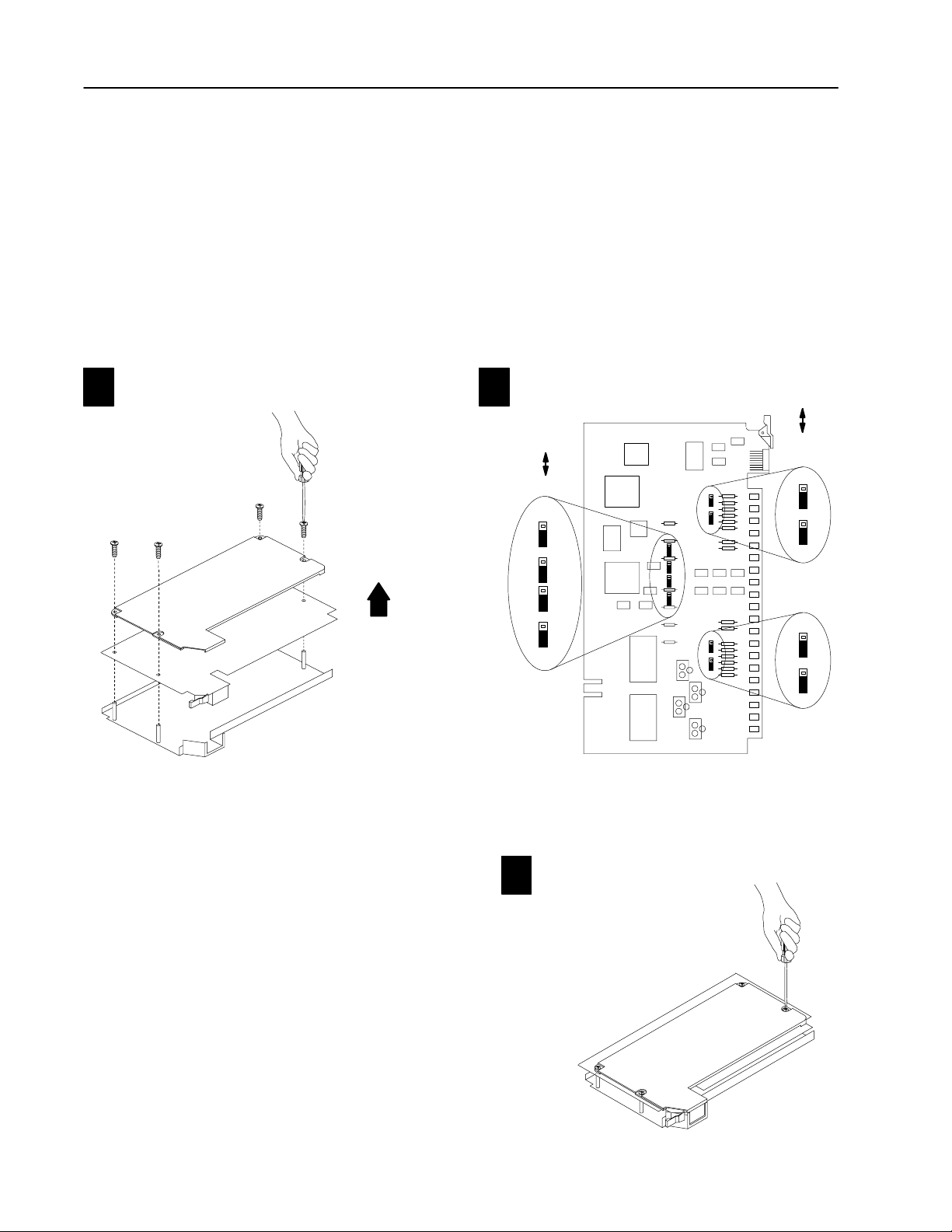
Replace Your QRC ModuleC–4
Check the Input Channel Jumpers
The CFM (QRC) module has user-selectable jumpers for each input
channel. These jumpers consist of one each:
• flowmeter jumpers (F0–F3) - set for low-pass filter or
high-speed operation
• gate jumpers (G0–G3) — set for +5-12V or +12-40V operation
Remove the four screws securing the side cover
11
to the module and remove the covers.
"
The CFM (QRC) module is configured for high-speed operation.
Before installing your CFM (QRC) module, make sure the input
channel jumpers are in their default positions.
Make sure the input channel jumpers➀ are in the default
12
positions shown below:
➁
FILTER
HIGH
SPEED
F1
F0
F3
F2
flowmeter jumpers
5-12V
12-40V
gate jumpers
G0
G1
G2
G3
Publication
17716.5.99 - December 1995
19805
➀
Jumpers
are shown in default settings.
➁
In the filter position, the module will not see frequencies
above 70Hz.
Reposition the cover and secure with
13
the fours screws removed in step 1.
19806
19813
Page 69
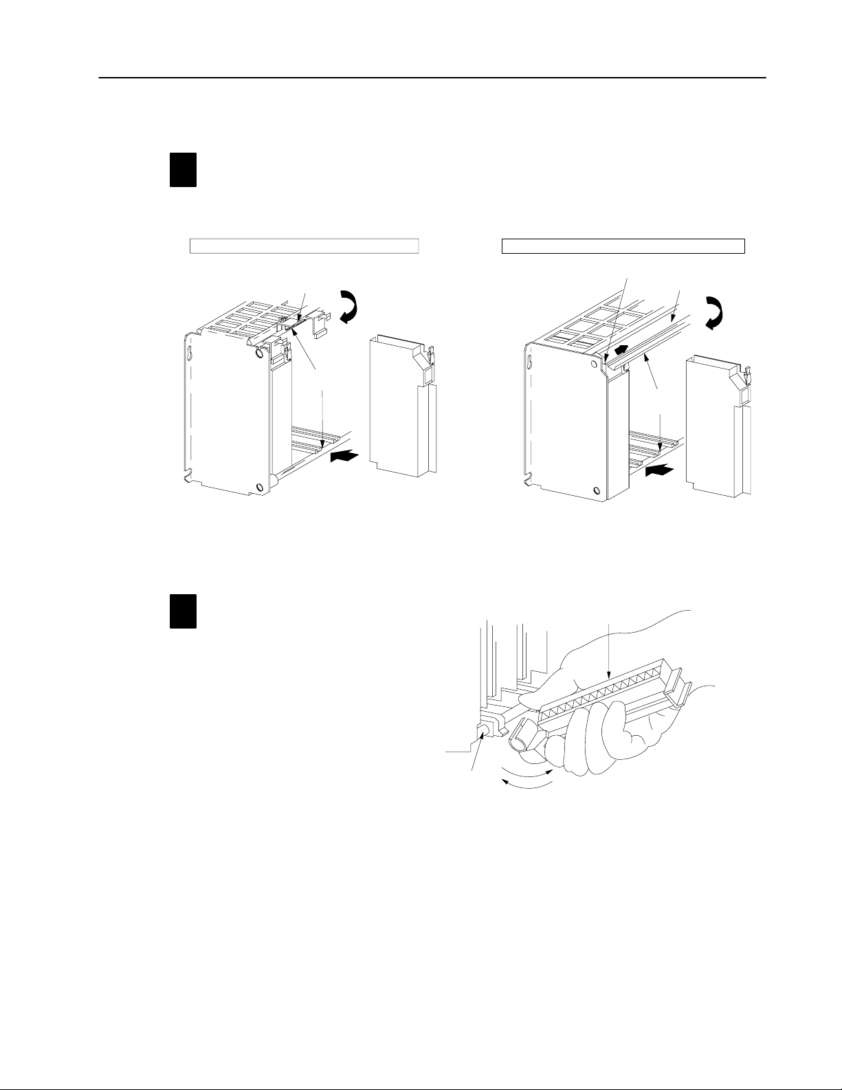
r
Install the CFM Module
Place the CFM (QRC) module in the card guides on the top and
1
bottom of the slot that guide the module into position.
Important: Apply firm even pressure on the module to seat it into
its backplane connector.
1771A1B, A2B, A3B, A3B1, A4B I/O chassis 1771A1B, A2B, A3B1, A4B Series B I/O chassis
locking
card guides
tab
Replace Your QRC Module C–5
locking
bar pin
locking bar
card guides
CFM (QRC) module
CFM (QRC) modu
Snap the chassis latch over
the top of the module to secure it.
Swing the chassis locking bar down into place to secu
the modules. Make sure the locking pins engage.
1
Attach the wiring arm (1771WN) to the horizontal
2
bar at the bottom of the I/O chassis.
The wiring arm pivots upward and connects with
the module so you can install or remove the
module without disconnecting the wires.
remove
horizontal bar
install
wiring arm
1771WN
17643
Publication
17716.5.99 - December 1995
Page 70

Replace Your QRC ModuleC–6
Make Connections to the New Wiring Arm
1
2
3
4
5
6
7
(+) Magnetic pickup and shield Channel A
8
(-) Magnetic pickup
9
10
11
12
13
(+) Magnetic pickup and shield Channel B
14
(-) Magnetic pickup
15
Overspeed solid state relay Channel A
16
17
18
Overspeed solid state relay Channel B
19
20
21
Solid state relay common
Connect your I/O devices to the 40-terminal field wiring arm
(cat. no. 1771-WN) shipped with the CFM module. Use the wiring
example on page C–7 for additional assistance on connecting
your devices.
NEW wiring arm (1771WN)OLD wiring arm (1771WG)
Even Numbered T
Customer
V DC #1 RET (Outputs 0 &1 RET)
erminals 240
F0 Input
F2 Input
Output 0
Odd Numbered T
2
4
6
8
10
12
14
16
18
20
22
24
26
28
30
32
34
36
38
40
1
3
5
7
9
11
F0 RET
13
15
17
19
21
23
F2 RET
25
27
29
31
33
Customer V DC #1 (5 to 40V)
35
Output 1
37
39
erminals 139
18322
Overspeed
1ms of frequency calculation.
outputs turned on within
actual wiring runs in this direction
The sensor cable must be shielded. The shield:
• must extend the length of the cable, but be connected only
at the 1771 I/O chassis
• must extend up to the point of termination
Important: The shield should extend to the termination point,
exposing just enough cable to adequately terminate the
inner conductors. Use heat shrink or another suitable
insulation where the wire exits the cable jacket.
10689I
Publication
17716.5.99 - December 1995
Page 71
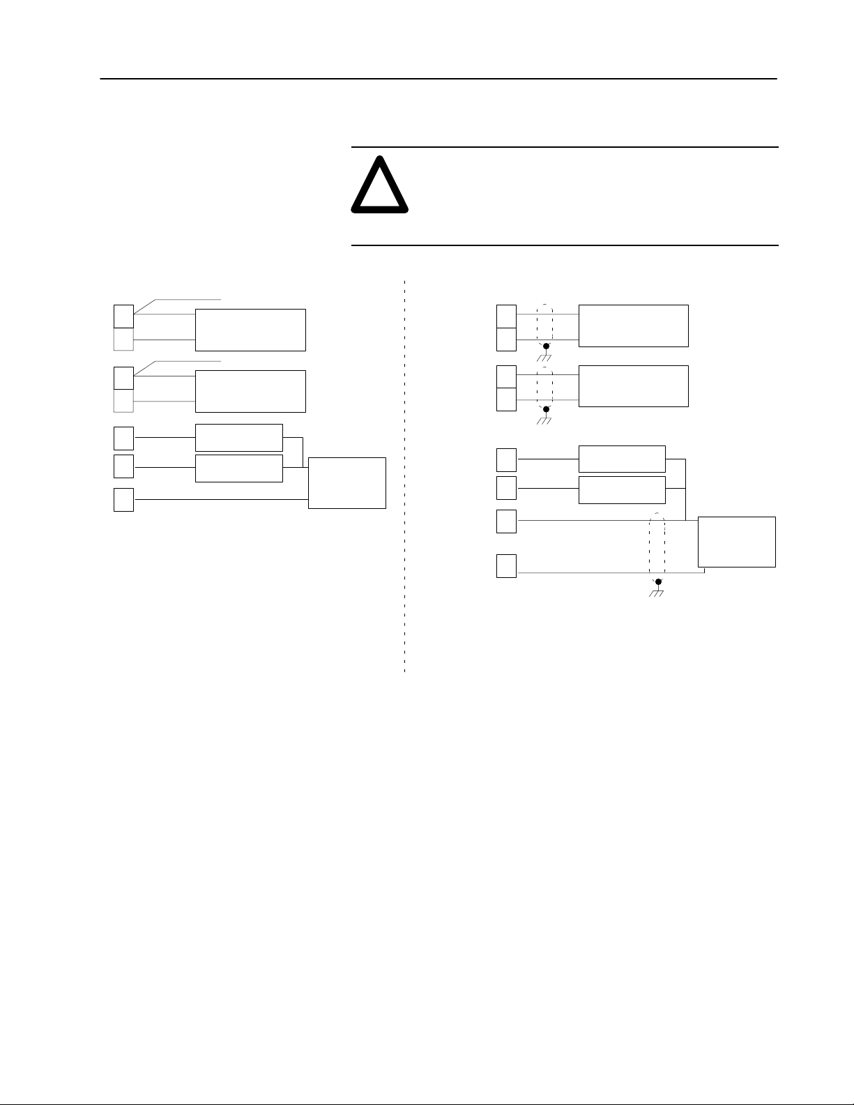
Wiring Example
ATTENTION: Pins15 & 18 (on the QRC module)
are switching negative (–) while pins 34 & 35
!
(on the CFM module) are switching positive (+).
Please take this into consideration when rewiring
your system.
Replace Your QRC Module C–7
QRC module CFM module
shield
(+)
turbine
flowmeter
or
magnetic pickup
shield
turbine flowmeter
or
magnetic pickup
channel A
channel A
+
+
(+)
external dc
power supply
(-)
12
11
24
23
34
35
13
14
15
18
21
7
8
(-)
(+)
(-)
overrange alarm
overrange alarm
36
33
➀
For new installations, terminate the shields at the chassis.
While not recommended, existing installations can continue
to terminate the shields at the return (RET) terminal.
➀
➀
+
+
(+)
turbine flowmeter
(-)
(+)
(-)
overrange alarm
overrange alarm
or
magnetic pickup
turbine flowmeter
or
magnetic pickup
channel A
channel A
-
-
(-)
external dc
power supply
(+)
➀
Publication
17716.5.99 - December 1995
Page 72

Replace Your QRC ModuleC–8
Resume Normal Operation
PLC5 Program Example
The
module to the PLC processor. This data is stored at N23:1. The BTR control file, starting at n23:60, is 5 words long.
Block transfer instructions use one binary file in a
data table section for module location and other
related data. The block transfer data file stores
data that you want transferred from the CFM
(QRC) module (when programming a BTR).
The address of the block transfer data files are
stored in the block transfer control file.
The programming terminal prompts you to create
a control file when a block transfer instruction is
being programmed. A different block transfer
control file is required for every module.
CFM (QRC)
CFM (QRC)
BTR EN Bit
N23:60
The CFM module, configured for QRC module emulation, operates
as a QRC module. Use the following section for reference on how
the CFM (QRC) module operates.
Important: The CFM module has 50mV sensitivity. This is
different than the QRC module, which had 20 to
300mV sensitivity, depending on the hardware level.
Edit Your Ladder Logic Program
To initiate communication between the CFM module and your
PLC processor, you must enter block transfer instructions into your
ladder logic program. Enter the following rung to establish
communication between the CFM module and your PLC processor.
module is located in rack 0, I/O group 1, slot 0. There are 3 words of data sent from the CFM (QRC)
CFM (QRC) BTR
CONTROL FILE
BTR
15
BLOCK TRANSFER READ
Rack
Group
Slot
Control Block
Data File
Length
N23:60
N23:1
00
EN
1
DN
0
ER
0
NContinuous
Publication
17716.5.99 - December 1995
Page 73

Replace Your QRC Module C–9
BTR
Read Data From the CFM Module
When configured for QRC module emulation, BTR programming
moves three words from the CFM module to the PLC processor’s
data table. The following BTR assignments apply when the CFM
module is configured for QRC module emulation.
BTR
Word
1
2
3
word 1
word 2 (ratemeter A)
Bit
15
14 13 12 11 10 09 08 07 06 05 04 03 02 01 00
Block
ID
Header
Input Channel Rate
Rate of Ratemeter A
Rate of Ratemeter B
*ALL numeric values are in binary*
BTR Word Descriptions
15 14 13 12 11 10 09 08 07 06 05 04 03 02 01 00
00000000 00010111
Header
will
be 7001 Hex or 28,673 binary. Identifies the
module as a CFM (QRC) module.
15 14 13 12 11 10 09 08 07 06 05 04 03 02 01 00
Rate indicates the calculated rate.
RANGE: 015,800Hz binary
Rates: 0169Hz are reported as zero
17015,800Hz are reported as calculated
> 15,800Hz are reported as 15,800
The rates in words 2 & 3 are updated every 13.5ms20ms
maximum. The greater the frequency, the faster the
update time. The accuracy of the returned rate is ±1Hz.
word 3 (ratemeter B)
15 14 13 12 11 10 09 08 07 06 05 04 03 02 01 00
Publication
17716.5.99 - December 1995
Page 74

Replace Your QRC ModuleC–10
O0 O1 O2 O3
STATUS
Interpret Status Indicators
Indicators
If indicator
ACTIVE
INPUTS
(F0 & F2)
ACTIVE
INPUTS/OUTPUTS
F0 F1 F2 F3
G2
STATUS
S1 S2 S3
FAULT
G3
G0 G1
O0 O1 O2 O3
S0
S4 S5 S6 S7
OUTPUTS➁ (O0 & O1)
STATUS S3 BTR is occurring BTR is not occurring
FAULT
➀
All other LED'
➁
Outputs
s are OFF in normal operation.
are not active if PLC processor is faulted or in Program mode.
➀
Is ON Is OFF
a. Check FAULT LED if on, follow the
the CFM module is receiving power and
operational
F0 - flashes with pulses at Channel A
F2 - flashes with pulses at Channel B
steps listed under if FAULT is ON.
b. Check power supply LEDs.
a signal is not present at the designated
input terminal (low)
O0 - indicates Channel A frequency
is ≥ 15,800Hz
O1 - indicates Channel B frequency
the output is off
is ≥ 15,800Hz
1. Turn off power to the I/O chassis
backplane and wiring arm.
2. Reseat the CFM (QRC) module in
the I/O chassis.
3. Restore power to the I/O chassis
backplane and wiring arm.
normal operation
Important: If the fault LED remains on,
there may be an internal problem.
Contact your local AllenBradley
representative for additional assistance.
Additional Feature
When you replace your existing QRC module with the CFM module,
you can set input channel jumpers for:
• TTL inputs (5-40v dc)
• 500mV ac sensitivity for improved noise immunity
For additional information on setting the input channel jumpers, see:
2
Install the
CFM Module
Publication
17716.5.99 - December 1995
Page 75

What This Appendix Contains
Appendix
D
Replace Your QRD Module
Use this appendix to install the CFM module as a replacement for the
QRD module.
To replace your QRD module you See page
Check Power Requirements . . . . . . . . . . . . . . . . . . . . . . . . . . . . . D-2
Remove Your QRD Module . . . . . . . . . . . . . . . . . . . . . . . . . . . . . D-2
Set the Configuration Jumpers . . . . . . . . . . . . . . . . . . . . . . . . . . . D-3
Set the Module Operation Jumper . . . . . . . . . . . . . . . . . . . . . . D-3
Check the Input Channel Jumpers . . . . . . . . . . . . . . . . . . . . . . D-4
Install the CFM (QRD) Module . . . . . . . . . . . . . . . . . . . . . . . . . . . D-5
Make Connections to the New Wiring Arm . . . . . . . . . . . . . . . . . . . D-6
Resume Normal Operation . . . . . . . . . . . . . . . . . . . . . . . . . . . . . . D-8
Edit Your Ladder Logic Program . . . . . . . . . . . . . . . . . . . . . . . D-8
Read Data From the CFM Module . . . . . . . . . . . . . . . . . . . . . . D-9
Reset Total and Overflow Flags . . . . . . . . . . . . . . . . . . . . . . . . D-10
Interpret Status Indicators . . . . . . . . . . . . . . . . . . . . . . . . . . . . D-11
Additional Feature . . . . . . . . . . . . . . . . . . . . . . . . . . . . . . . . .
D-11
What the CFM Module Does
Important: We assume that you are using a QRD module in your
existing system and that you are familiar with the I/O
module installation/removal procedures.
The CFM (QRD) module interfaces PLC processors with magnetic
pickups, single channel shaft encoders, turbine flowmeters, or any
source of TTL pulses.
When configured for QRD operation, the CFM (QRD) module
calculates the frequency once per second, independent of the
pulse edges.
The CFM (QRD) module is generally compatible with, but does not
require the use of, turbine flowmeter signal preconditioning modules.
It provides rate and count data in 2’s complement binary format to
the PLC processor’s data table through block data transfers.
Rates as high as 10.0kHz and counts as large as 32,767 are
supported. At overflow, the count continues from zero and an
overflow flag is set. The overflow flag can be reset by the ladder
logic. In addition, the PLC processor can reset any or all
counts directly.
Important: Input frequencies > 30.0kHz may return unpredictable
results in the BTR file.
Publication
17716.5.99 - December 1995
Page 76
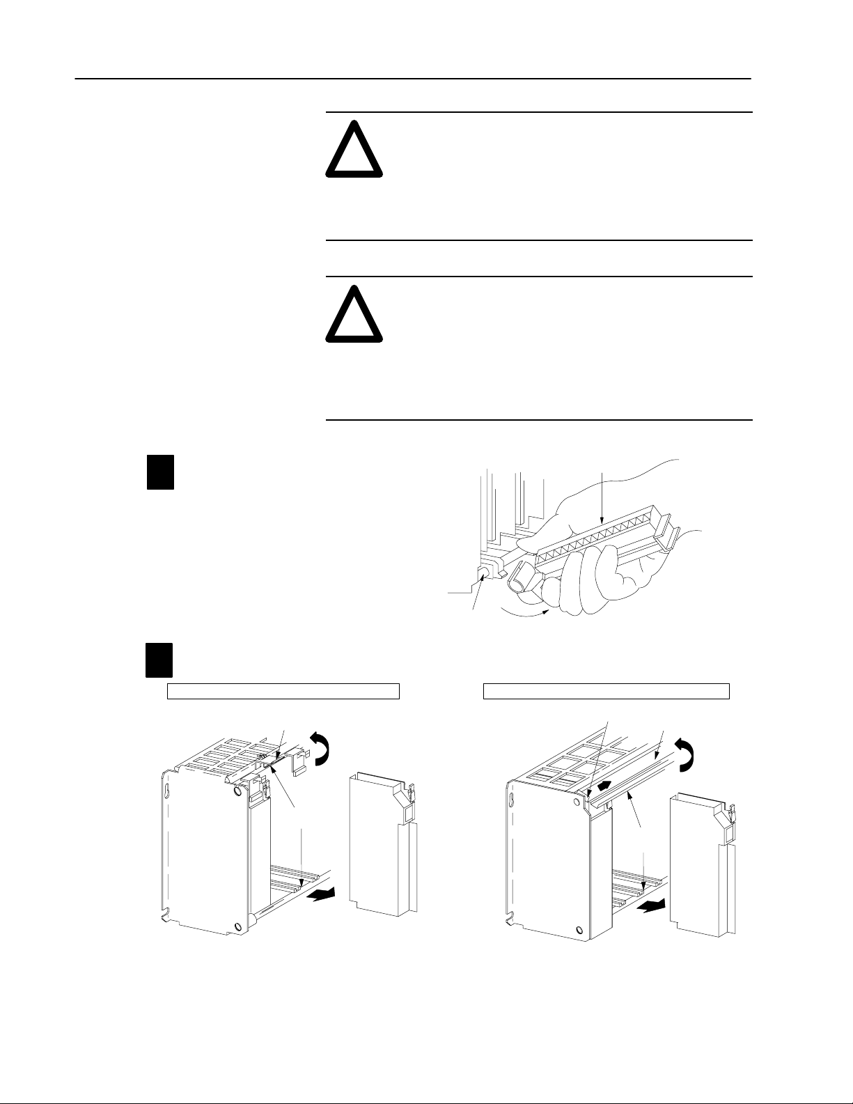
Replace Your QRD ModuleD–2
Check Power Requirements
Remove Your QRD Module
Detach and remove wiring arm (1771WG) from
1
1
the horizontal bar at the bottom of the I/O chassis.
ATTENTION: The maximum current drawn by the
CFM(QRD) module is 1.0A. This current (1.0A) is
!
!
0.5A greater than the maximum current drawn by your
QRD module (0.5A).
Consider the power usage of all modules in the I/O
chassis to prevent overloading either the chassis
backplane or power supply.
ATTENTION: Remove power from the 1771 I/O
chassis backplane and wiring arm before you remove
your QRD module. Failure to remove power from the
backplane could cause:
• injury
• equipment damage due to unexpected operation
• degradation of performance
wiring arm
horizontal bar
Remove the QRC module from the I/O chassis.
2
1771A1B, A2B, A3B, A3B1, A4B I/O chassis 1771A1B, A2B, A3B1, A4B Series B I/O chassis
locking
tab
card guides
QRC module
Pull on the QRC module to slide it out of the I/O chassis.
remove
locking bar pin
locking bar
card guides
1771WG
QRC module
19809
Publication
17716.5.99 - December 1995
Page 77

Replace Your QRD Module D–3
Set the Configuration Jumpers
You check and/or set these jumpers:
• module operation jumper
• input channel jumpers
Set the Module Operation Jumper
To use the CFM module as a replacement for a QRD module,
set the operation jumper in the QRD position
(default setting = CFM position).
CFM module
CFM
QRC
QRD
19807
Publication
17716.5.99 - December 1995
Page 78
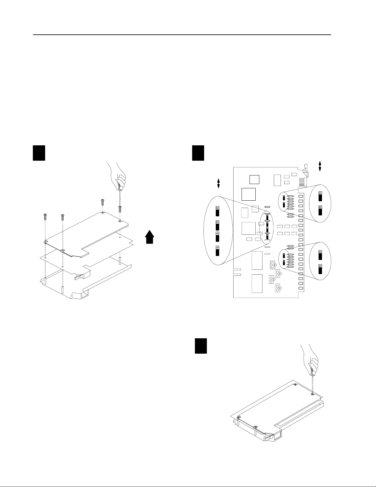
Replace Your QRD ModuleD–4
Check the Input Channel Jumpers
The CFM (QRD) module has user-selectable jumpers for each input
channel. These jumpers consist of one each:
• flowmeter jumpers (F0–F3) - set for low-pass filter or
high-speed operation
• gate jumpers (G0–G3) — set for +5-12V or +12-40V operation
The CFM (QRD) module is configured for high-speed operation.
Before installing your CFM (QRD) module, make sure the input
channel jumpers are in their default positions.
Remove the four screws securing the side cover
11
to the module and remove the covers.
19805
Make sure the input channel jumpers
12
positions shown below:
➁
FILTER
HIGH
SPEED
F1
F0
F3
F2
flowmeter jumpers
➀
Jumpers
are shown in default settings.
➁
In
the filter position, the module will not see
frequencies above 70Hz.
➀
are in the default
gate jumpers
5-12V
12-40V
G0
G1
G2
G3
19806
Publication
17716.5.99 - December 1995
Reposition the cover and secure with
13
the fours screws removed in step 1.
19813
Page 79

Install the CFM Module
Place the CFM (QRD) module in the card guides on the top and
11
bottom of the slot that guide the module into position.
Important: Apply firm even pressure on the module to seat it into
its backplane connector.
1771A1B, A2B, A3B, A3B1, A4B I/O chassis 1771A1B, A2B, A3B1, A4B Series B I/O chassis
Replace Your QRD Module D–5
locking
tab
card guides
Snap the chassis latch over
the top of the module to secure it.
Attach the wiring arm (1771WN) to the horizontal
12
bar at the bottom of the I/O chassis.
The wiring arm pivots upward and connects with
the module so you can install or remove the
module without disconnecting the wires.
locking bar
locking bar pin
card guides
CFM (QRD) module
CFM (QRD) module
Swing the chassis locking bar down into place to secure
the modules. Make sure the locking pins engage.
19809
wiring arm
1771WN
horizontal bar
install
Publication
17643
17716.5.99 - December 1995
Page 80
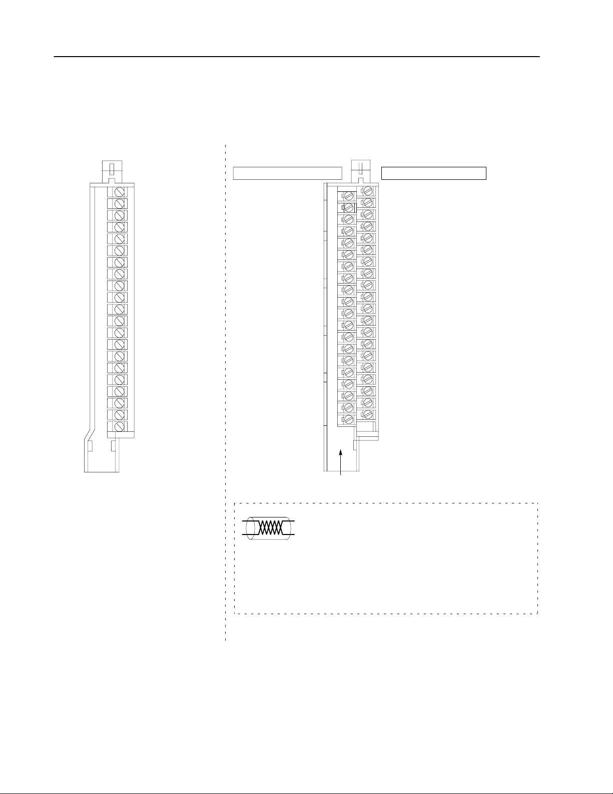
Replace Your QRD ModuleD–6
Make Connections to the New Wiring Arm
not
used
1
not used
2
Channel 1 +
3
Channel 1 -
4
shield
5
Channel 2 +
6
Channel 2 -
7
shield
8
Channel 3+
9
Channel 3 -
10
shield
11
Channel 4 +
12
Channel 4 -
13
shield
14
not used
15
not used
16
TTL
17
not used
18
Channel 3, 4 level
19
Channel 1, 2 level
20
not used
21
Connect your I/O devices to the 40-terminal field wiring arm
(cat. no. 1771-WN) shipped with the CFM module. Use the wiring
examples on page D–7 for additional assistance on connecting
your devices.
NEW wiring arm (1771WN)OLD wiring arm (1771WG)
Even Numbered T
erminals 240
F0 Input
F1 Input
F2 Input
F3 Input
Odd Numbered T
11
13
15
17
19
21
23
25
27
29
31
33
35
37
39
1
3
5
7
9
F0 (TTL)
F0 RET
F1 (TTL)
F1 RET
F2 (TTL)
F2 RET
F3 (TTL)
F3 RET
2
4
6
8
10
12
14
16
18
20
22
24
26
28
30
32
34
36
38
40
erminals 139
➀
18322
actual wiring runs in this direction
The sensor cable must be shielded. The shield:
• must extend the length of the cable, but be connected
only at the 1771 I/O chassis
• must extend up to the point of termination
Important: The shield should extend to the termination point,
exposing just enough cable to adequately terminate the
inner conductors. Use heat shrink or another suitable
insulation where the wire exits the cable jacket.
➀
To use a channel in TTL, jumper the appropriate TTL pin to the appropriate
RET. To use Channel 1 in TTL, jumper pin 9 to pin 11.
Publication
17716.5.99 - December 1995
Page 81

Wiring Examples
Replace Your QRD Module D–7
wiring for magnetic pickups or flowmeters
3
4
5
6
7
8
9
10
11
12
13
14
wiring for active TTL drivers
3
4
6
7
QRD module CFM module
(+)
shield
shield
shield
shield
shield
shield
(-)
(+)
(-)
(+)
(-)
(+)
(-)
turbine
flowmeter
1
turbine
flowmeter
2
turbine
flowmeter
3
turbine
flowmeter
4
TTL
channel 1
TTL
channel 2
11
12
15
16
23
24
27
28
9
11
12
13
logic
➁
(-)
turbine
flowmeter
(+)
1
(-)
turbine
flowmeter
(+)
2
(-)
turbine
flowmeter
(+)
(-)
turbine
flowmeter
(+)
4
ground channel 0
TTL
F0
3
➀
9
10
11
12
13
17
19
20
8
shield
logic ground
TTL
channel 3
15
16
21
23
TTL
channel 4
shield
TTL
channel 3 & 4 level
24
25
27
28
logic
ground channel 1
➁
logic ground channel 2
➁
logic ground channel 3
➁
TTL
F1
TTL
F2
TTL
F3
channel 1 & 2 level
➀
To use a channel in TTL, jumper the appropriate
TTL pin to the appropriate RET.
To use Channel 1 in TTL, jumper pin 9 to pin 11.
Signal types can be mixed in any combination on
the CFM module.
➁
For new installations, terminate the shields at the
chassis. While not recommended, existing
installations can continue to terminate the shields
at the return (RET) terminal.
Publication
17716.5.99 - December 1995
Page 82
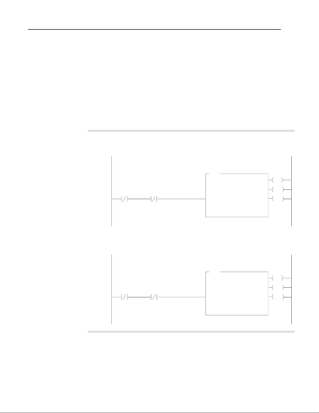
Replace Your QRD ModuleD–8
Resume Normal Operation
Program Example
The
module to the PLC processor
Block transfer instructions use one binary file
in a data table section for module location and
other related data. The block transfer data file
stores data that you want transferred to the
module (when programming a BTW) or from
the module (when programming a BTR).
The address of the block transfer data files are
stored in the block transfer control file.
The programming terminal prompts you to
create a control file when a block transfer
instruction is being programmed.
A different block transfer control file is
required for every module.
CFM (QRD)
The CFM module, configured for QRD module emulation, operates
as a QRD module. Use the following section for reference on how
the CFM (QRD) module operates.
Edit Your Ladder Logic Program
To initiate communication between the CFM (QRD) module and
your PLC processor, you must enter block transfer instructions into
your ladder logic program. The following program example
illustrates the minimum programming required for this
communication to take place.
module is located in rack 0, I/O group 1, slot 0. There are 9 words of data sent from the CFM (QRD)
CFM (QRD)
BTR EN BIT
N23:50
15
. This data is stored at N23:21. The BTR control file, starting at n23:50, is 5 words
CFM (QRD) BTR
CONTROL FILE
CFM (QRD)
EN BIT
BTW
N23:55
15
BTR
BLOCK TRNSFR READ
RACK
GROUP
SLOT
CONTROL BLOCK0N23:50
DATA FILE
LENGTH
00
N23:21
NCONTINUOUS
long.
EN
1
DN
0
ER
The
to the CFM (QRD) module. This data is stored at N23:1. The BTR control file, starting at n23:55, is 5 words long.
Note that the BTW is switch selectable, and its
length is one word. The block transfer should only
be sent once unless the ladder intelligently sets
and clears the reset bits within the block transfer
data. As an example, the ladder might set the
reset bit at the time of overflow. If the block
transfer is sent continuously and the reset bits
contained within the block transfer data are simply
left set to 1", the transfers will constantly be
resetting the totalizer(s) and/or overflow flags of
the specified channels.
CFM (QRD) module is located in rack 0, module group 1, slot 0. There is 1 word of data
CFM
CONTROL FILE
CFM (QRD)
BTR EN BIT
N23:50
15
CFM (QRD)
BTW
EN BIT
N23:55
15
BTR
BLOCK TRNSFR WRITE
RACK
GROUP
SLOT
CONTROL BLOCK0N23:55
DATA FILE
LENGTH
sent from the PLC processor
(QRD)
BTW
N23:1
00
EN
1
DN
0
ER
NCONTINUOUS
Publication
17716.5.99 - December 1995
Page 83
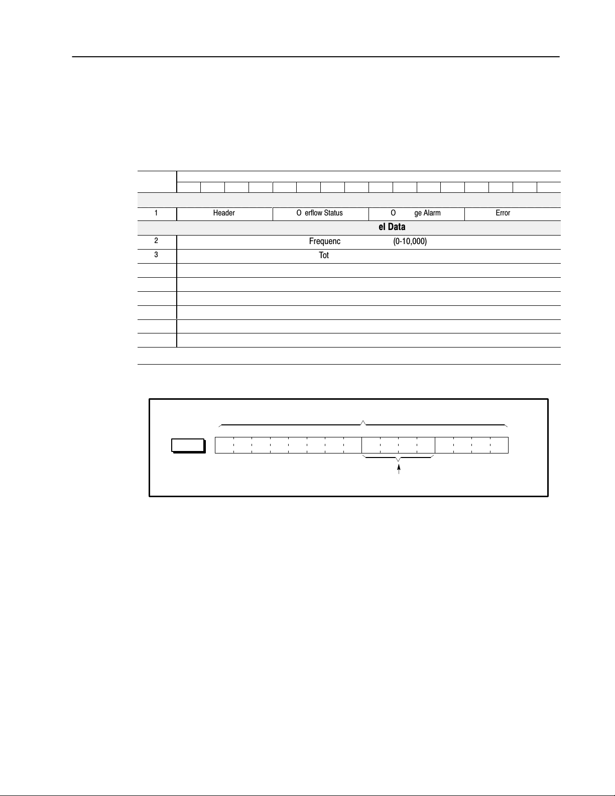
Replace Your QRD Module D–9
BTR
Read Data From the CFM Module
When configured for QRD module emulation, BTR programming
moves nine words from the CFM module to the PLC processor’s
data table. The following BTR assignments apply when the CFM
module is configured for QRD module emulation.
BTR
Word
1
2
3
4
5
6
7
8
9
15
word #
Bit
14 13 12 11 10 09 08 07 06 05 04 03 02 01 00
Block
ID & Channel Status
Header
Overflow
Status
Input
Overrange Alarm
Channel Data
Error Code
Frequency on Channel 1 (010,000)
Total on Channel 1 (032,767)
Frequency on Channel 2 (010,000)
Total on Channel 2 (032,767)
Frequency on Channel 3 (010,000)
Total on Channel 3 (032,767)
Frequency on Channel 4 (010,000)
Total on Channel 4 (032,767)
*ALL numeric values are in binary*
BTR Word Description Key
Bits
15 14 13 12 11 10 09 08 07 06 05 04 03 02 01 00
Description of what these bits are used for.
Publication
17716.5.99 - December 1995
Page 84

word 1
Replace Your QRD ModuleD–10
BTR Word Descriptions
15 14 13 12 11 10 09 08 07 06 05 04 03 02 01 00
0001.
Header must be 0001
Identifies the module as
a CFM (QRD) module.
word 5 (channel 0)
word 2 (channel 1)
word 15 (channel 1)
word 4 (channel 2)
word 25 (channel 2)
word 6 (channel 3)
word 35 (channel 3)
word 8 (channel 4)
word 5 (channel 0)
word 3 (channel 1)
word 15 (channel 1)
word 5 (channel 2)
word 25 (channel 2)
word 7 (channel 3)
word 35 (channel 3)
word 9 (channel 4)
Overflow Status
on if rollover has occurred
(counter has exceeded maximum
value of 32,767 and rolled over to 0).
This can only be reset by BTW
Overflow Reset.
b08 = Channel 1 b10 = Channel 3
b09 = Channel 2 b11 = Channel 4
Overrange Alarm
on if the frequency is > 10.0kHz.
Frequency will be reported as 0.0Hz
and count will be reset to 0.
b04 = Channel 1 b06 = Channel 3
b05 = Channel 2 b07 = Channel 4
VALUES: 0 = frequency < overrange value
1 = frequency ≥ overrange value
VALUES: 0 = rollover has not occurred
1 = rollover has occurred
15 14 13 12 11 10 09 08 07 06 05 04 03 02 01 00
Frequency indicates the calculated
frequency for the input channels.
15 14 13 12 11 10 09 08 07 06 05 04 03 02 01 00
Total the total counts registered
by the input channel.
RANGE: 010,000Hz
Frequency = 0 if Overrange Alarm = 1 (is ON).
RANGE: 032,767
Total = 0 if Overrange Alarm = 1 (is ON).
Error Code displays error
code hex value:
0 = Valid Data
2 = Block Transfer Syntax Error:
BTW word 1, bits 08-15
any bit is ON (= 1)
15 14 13 12 11 10 09 08 07 06 05 04 03 02 01 00
word 1
0000. 0000.
All of these bits must be OFF (= 0).
If any bit is ON, BTR word 1, bits 0003
will display an error code of 2 (hex value).
Reset Total and Overflow Flags
Any or all of the totalizers and overflow flags can be reset using a
BTW command sent to the CFM module from the PLC processor.
The BTW data word can be changed through the ladder logic, or by
editing the data table.
BTW Word Description
Total Reset
Overflow Reset
reset the overflow flag (these bits are
level sensitive upon receipt of BTW).
b04 = Channel 1 b06 = Channel 3
b05 = Channel 2 b07 = Channel 4
reset the total count
(these bits are level sensitive).
b00 = Channel 1 b02 = Channel 3
b01 = Channel 2 b03 = Channel 4
VALUES: 0 = not reset 1 = reset
VALUES: 0 = not reset 1 = reset
➀
Resetting the total count will automatically reset its respective overflow flag(s).
Continuously doing BTW's with T
otal Reset
= 1 (reset) will affect the accuracy of the frequency.
➀
Publication
17716.5.99 - December 1995
Page 85

Interpret Status Indicators
Replace Your QRD Module D–11
Indicators
➀
All other LED'
ACTIVE
INPUTS/OUTPUTS
F0 F1 F2 F3
G0 G1 G2 G3
O0 O1 O2 O3
STATUS
S0
S1 S2 S3
S4 S5 S6 S7
FAULT
s are OFF in normal operation.
If indicator
ACTIVE
INPUTS
(F0 F3)
STATUS S1
S2
S3
S4
FAULT
➀
Is ON Is OFF
the CFM module is successfully receiving
power and operational
F0 - flashes with pulses at Channel 1
F1 - flashes with pulses at Channel 2
F2 - flashes with pulses at Channel 3
F3 - flashes with pulses at Channel 4
BTW invalid (BTW word 1, bits 0815) 0 0
BTW is occurring
BTR is occurring
frequency > 10.0kHz (overrange) on
any channel
1. Turn off power to the I/O chassis
backplane and wiring arm.
2. Reseat the CFM module in the
I/O chassis.
3. Restore power to the I/O chassis
backplane and wiring arm.
Important: If the fault LED remains on,
there may be an internal problem.
Contact your local
AllenBradley representative for
additional assistance.
a. Check FAULT LED if on, follow the
steps listed under if FAULT is ON.
b. Check power supply.
a signal is not present at the designated
input terminal
BTW is valid
BTW is not occurring
BTR is not occurring
all frequencies within operating range
normal operation
Additional Feature
When you replace your existing QRD module with the CFM module,
you can set input channel jumpers for:
• 500mV ac sensitivity for improved noise immunity
• frequencies > 70Hz (flowmeter filter jumpers)
For additional information on setting the input channel jumpers, see:
2
Install the
CFM Module
Publication
17716.5.99 - December 1995
Page 86

What This Appendix Contains
Configure the CFM Module
Appendix
E
Using I/O Configuration
Software
Use this appendix along with the PLC-5 Programming Software,
I/O Configuration Software manual (publication 6200-6.4.12) to
configure the CFM module using I/O Configuration software.
To configure the CFM module, you use these screens:
• Block Transfer Data screen
• Channel Setup screen
• Output Setup screen
• Monitor screen
Choose one:
a b
I/O Module
System Overview
Edit
F2
BT
Data T
ables
F2
You cannot edit the information on this screen.
I/O Module
or
System Overview
Edit
Channel Edit
F3
BT Data Tables
or
System Overview
F2
BT Data Tables
F2
c
I/O Module
Monitor
F3
F6
Block Transfer Data Screen
Use the Block Transfer Data screen to display an image of the
PLC processor data tables for the CFM module.
1771–CFM Series A Block Transfer Data Rack–Group–Module: 0–0–0
Configuration Data (BTW) Input Data/Status (BTR)
N7:10 12032 17425 12561 8451 –28572 N7:100 8192 16384
N7:102 8451 0
N7:15 10 0 15000 2000 0 N7:104 21712 23
N7:106 0 430
N7:20 0 0 0 0 0 N7:108 0 0
N7:110 0 0
N7:25 0 0 0 0 0 N7:112 0 0
N7:114 0 0
N7:30 0 0 0 0 2048 N7:116 0 0
N7:118 0 0
N7:35 1000 0 0 5000 0 N7:120 0 0
N7:122 0 4232
N7:40 1 2 0 0 0 N7:124 1 5499
N7:126 446 4049
Press arrow keys or PgUp/PgDn to see more data.
Rem RUN mod 1 of 1 Addr#42:CFM4B
Change I/O Channel Output Monitor Change Display
Mode Ovrview Setup Setup Radix Symbols
F1 F2 F3 F4 F5 F6 F7
Publication
17716.5.99 - December 1995
Page 87

Using I/O Configuration SoftwareE–2
Shows current values for each channel
(these values reflect the data received
the last time a BTR was completed).
The PLC processor must be in Run
mode if you want to receive current data
from the CFM module.
Shows current programming
for each channel and lets you
change the channel programming.
Fields inapplicable in the
programmed channel mode are
shown as dashes
and cannot be edited.
Choose one:
a b
I/O Module
System Overview
Edit Channel Setup
Output Setup
or
or Monitor
or BT Data
F3F2
Ladder Editor
or
Main Menu
Cursor to
BT instruction
Edit
I/O Edit
Use PageUp or PageDown to move
through the channel setup screens.
Channel Setup Screen
1771–CFM Series A Channel Setup Rack–Group–Module: 0–0–0
channel 0 channel 1 channel 2 channel 3
current values:
channel mode high–res freq (not used) totalizer noreset totzr
frequency 43.0 15,487 258
total counts ––– 3,881,128 1,111,111
acceleration 0 359 0
–––––––––––––––––––– channel 0 channel 1 channel 2 channel 3
new channel mode high–res freq (not used) totalizer noreset totzr
minimum sample time 10 ms 1000 ms 0 = 100 ms
for frequency
acceleration 2,000 5,000 disabled
alarm value
accel sample time 100 rolling avg –––
(freq intervals)
highest allowed 60,000 0 0
frequency
Press F9(Toggle) to change channel mode.
Rem RUN mod 1 of 1 Addr#42:CFM4B
Change I/O Output Monitor BT Data Default Toggle Accept
Mode Ovrview Setup Tables Config
F1 F2 F4 F5 F6 F8 F9 F10
–––––––––––––––––––– channel 0 channel 1 channel 2 channel 3
lowest measurable 1 Hz ––– –––
frequency
c
F10
F2
end sample on time only ––– –––
counts to end ––– ––– –––
sampling
frequency resolution 0.1 Hz ––– –––
frequency scalers 1/1 1/1 1/60
(multiply/divide)
Press F9(Toggle) to change bandwidth limit.
Rem RUN mod 1 of 1 Addr#42:CFM4B
Change I/O Output Monitor BT Data Default Toggle Accept
Mode Ovrview Setup Tables Config
F1 F2 F4 F5 F6 F8 F9 F10
–––––––––––––––––––– channel 0 channel 1 channel 2 channel 3
scalers for total ––– 1/2 1/1
(multiply/divide)
rollover value ––– 0 5,000,000
tied to outputs 0,2,3 1 none
reset total ––– disabled –––
reset overflow ––– disabled disabled
start prover ––– enabled enabled
prover type, uni ––– bi uni
or bidirectional
Enter rollover value (0 to 9,999,999).
>
Rem RUN mod 1 of 1 Addr#42:CFM4B
Change I/O Output Monitor BT Data Default Accept
Mode Ovrview Setup Tables Config
F1 F2 F4 F5 F6 F8 F10
Publication
Press (F3) Channel Setup to configure individual channels or (F10) - Accept to accept
your edits. We suggest that you complete your edits on all screens before accepting the edits.
17716.5.99 - December 1995
Page 88

Using I/O Configuration Software E–3
Current values Displays In mode(s)
channel mode the current channel mode as returned in the BTR data file by the module
frequency the current scaled frequency
total counts the scaled total counts
all
all
T,
NR
T
if acceleration alarm value
acceleration
0 0, value = the acceleration (change in scaled frequency per second)
all
= 0, value = 0
Current programming You In mode(s)
press (F9) Toggle to select a mode of operation for the input channel:
❯ not used
❯ totalizer
❯ noreset totzr (nonresettable totalizer)
new channel mode
❯ high-res freq (highresolution frequency)
❯ direction (direction sensor)
all
Important: The Highresolution frequency and Direction Sensor modes each
occupy two channels and are selected via channel 0 (channel 1
unused) or channel 2 (channel 3 unused).
enter the minimum time value the CFM module will spend to determine frequency
minimum sample time
for frequency
RANGE: 4-1000ms (03 = DEFAULT)
DEFAULT (if you enter 0): 100ms (T, NRT) 4ms (HR, DS)
In Direction Sensor, this time is used to determine the maximum sample time and
T,
NRT, HR
minimum frequency and does not actually determine the time period.
acceleration alarm
value
enter an alarm value of 0 to 32,767
DEFAULT (if you enter 0): all acceleration features of the module are disabled
all
only when the acceleration alarm value 0 0
accel sample time
(freq intervals)
enter a number to determine how many frequency intervals (1 to 750) should be
spanned in computing acceleration
DEFAULT (if you enter 0): acceleration calculated as rolling average over 5
T,
NRT, HR
samples
enter a value up to 120,000Hz for the overspeed threshold
DEFAULT (if you enter 0): 120,000Hz
highest allowed
frequency
The highest allowed frequency is in Hz, not in scaled frequency units.
For example, if you select 120,000Hz as the highest allowed frequency and select
T,
NRT, HR
frequency scalers of 1/60, the module sets the overspeed bit in the BTR for any
scaled frequency above 2000 (120,000Hz).
lowest measurable
frequency
press (F9) Toggle to select 1 Hz (full frequency range, 1 Hz to 100kHz)
or 1/sample time this field = Bandwidth Limit in BTW configuration block
HR
press (F9) Toggle to select time only or time/counts (time only means when the
end sample on
minimum sampling time has elapsed and at least one count has been received)
HR
this field = Terminate Enable in BTW configuration block
counts to end
sampling
enter the number of counts (032,767) to end sampling on
HR
select the precision of the frequency (1Hz or 0.1Hz) returned in the BTR
frequency resolution
(if you have scaling programmed for frequency, the resolution will be in whole
HR
numbers of tenths of scaled frequency units)
frequency scalers
(multiply/divide)
enter a multiplier and divisor separated by a (/) to have the module report
frequency in units meaningful to your application
(the multiplier must be ≤ the divisor)
RANGE: 1255 DEFAULT: 1/1 (no scaling)
For example, if one count represents 7 gallons, you could scale frequency to
all
gallons per minute by entering scalers of 7/60.
Scaling affects only the frequency and acceleration value that the module returns
in the BTR. All programming in the BTW - e.g. highest allowed frequency, output
ON and OFF values still in Hz.
Mode abbreviations:
Totalizer = T
Nonresettable T
otalizer = NRT Highresolution Frequency = HR Direction Sensor = DS
Publication
17716.5.99 - December 1995
Page 89

Using I/O Configuration SoftwareE–4
enter a multiplier and divisor here, separated by a (/) to have the module report
total counts in units meaningful to your application
(the multiplier must be ≤ the divisor)
scalers for total
(multiply/divide)
RANGE: 032,767 DEFAULT: 1/1 (no scaling)
For example, if 15 counts represent 2 gallons, you could scale counts to gallons by
entering scalers of 2/15.
Scaling affects only the total counts value that the module returns in the BTR.
All programming in the BTW - e.g. rollover value, output ON and OFF values is
still in Hz .
enter a count value that the totalizer will reset or rollover to 0 at (when the unscaled
rollover value
count reaches that value, the module sets the overflow status bit in the BTR and
starts counting again from 0)
RANGE: 0-9,999,999 DEFAULT (if you enter 0): 10,000,000
tied to outputs
reset total see if the Total Reset (BTW word 1, bits 0030) is ON (this field is display only).
reset overflow see if the Overflow Reset (BTW word 1, bits 0407) is ON (this field is display only).
see the output(s) that are currently tied to this input channel (this field is display
only to tie outputs to a different input channel, use the Output Setup screen.
see the current settings in the BTW data file (you must make any changes to this
start prover
field through a running program on the PLC processor, or by directly setting bits in
the BTW; you can not edit these fields with the I/O Configuration software)
prover type, uni
or bidirectional
Mode abbreviations:
Totalizer = T
Nonresettable T
press (F9) Toggle to select the type of prover you are using in your application
0 = unidirectional 1 = bidirectional.
otalizer = NRT Highresolution Frequency = HR Direction Sensor = DS
In mode(s)Current programming You
T,
NR
T
T,
NR
T
all
T
T,
NR
T
T,
NR
T
T,
NR
T
Publication
17716.5.99 - December 1995
Page 90

Choose one:
a b c
or
Ladder Editor
Main Menu
General Utility
F7
I/O Ovrview
F9
Edit
F2
Ladder Editor
Main Menu
Cursor to
BT instruction
Edit
F10
I/O Edit
F2
or
Counter Setup
or Monitor
or BT Data
Output Setup
F4
Using I/O Configuration Software E–5
Output Setup Screen
1771–CFM Series A Output Setup Rack–Group–Module:
0–0–0
output current tied to forced or
number status channel triggered by ON when >= OFF when >=
0 off 0 rate/frequency 1,000 25,000
1 off 2 total 1,000 3,500,000
2 on 0 rate/frequency 1,000 12,000
3 off 0 acceleration 100 0
Enter numeric trigger value, or press F9 to change direction trigger.
>
Rem RUN mod 1 of 1 Addr#42:CFM4B
Change I/O Channel Monitor BT Data Default Accept
Mode Ovrview Setup Tables Config
F1 F2 F3 F5 F6 F8 F10
Output Setup
F4
This field Is used to
output number
current status
tied to channel
forced or
triggered by
display the output numbers (03)
display each output's current status (ON or OFF) these values reflect the data received the last time a BTR
was
completed (
select
the input channels
ber
select what channel characteristic the output is triggered ON or OFF by (the default is disabled)
press (F9) Toggle to select one of these characteristics:
Disabled: always forces the output to an OFF state.
If you select Disabled, you cannot tie the output to a
channel, and you cannot enter ON/OFF values.
Rate/Frequency: specify ON and OFF values in Hz,
not in scaled frequency units.
% of Full Scale: specify ON and OFF values as
percentages of the channel's highest allowable
frequency from the Channel Setup screen.
T,
NRT, HR
Acceleration: channel's alarm must be nonzero.
Specify ON and OFF values of -32,768 to 32,767
Hz/s, representing a change per second in
unscaled frequency.
Total: Specify ON and OFF values in unscaled
counts from 0 to 9,999,999. If the channel has a
nonzero rollover value programmed, the ON and
OFF values must be less than the rollover.
T
, NR
T
Direction: For ON and OFF values, press (F9)
Toggle to select stop, CW (clockwise), or CCW
(counterclockwise).
ON when >=
OFF when >=
Enter a value between 0 and 9,999,999.
The output state transitions from an OFF state to an ON state when the monitored value exceeds the ON count.
The output state transitions from an ON state to an OFF state when the monitored value exceeds OFF.
Press (F4) Output Setup for other configuration choices or (F10) - Accept to accept
your edits. We suggest that you complete your edits on all screens before accepting the edits.
the PLC processor must be in Run mode if you want to receive current data from the CFM module
(03)
that the output channel is tied to (default is None) Press (F9) - T
oggle to select num
Overflow: If you specify this mode, you must tie the
output to a channel, and that channel's mode must be
totalizer or nonresettable totalizer. You cannot enter
ON and OFF values. The output will be ON when the
overflow bit is set in the BTR, and OFF when the overflow
bit is clear.
Forced On: If you specify this mode, you cannot tie the
output to a channel or enter ON and OFF values.
Prover running: You cannot enter ON and OFF values.
The output will be ON during a prover run and OFF at
T
, NR
other times.
all
Prover range: For ON and OFF values,
press (F9) Toggle to select from these prover values
T
prover not selected in fwd (forward) leg
prover selected but not running fwd leg done
in rev (reverse) leg done
If the channel's prover type of the Channel Setup screen
is unidirectional, fwd leg done" and in rev leg" are not
valid settings for ON and OFF values.
T,
NR
DS
T
)
Publication
17716.5.99 - December 1995
Page 91

Using I/O Configuration SoftwareE–6
Monitor Screen
a b
Ladder Editor
Main Menu
Cursor to
BT instruction
Data Monitor
F8
I/O Monitor
F1
Output Setup
F4
Choose one:
I/O Module
or
System Overview
Monitor
F3
Edit
F2
or
Output Setup
F4
Counter Setup
or
or Output Setup
or BT Data
Monitor
F5
Use the monitor screen to check and verify the configuration data.
c
The values on this screen reflect the data received the last time a
BTR was completed. The processor must be in Run mode if you
want to receive current data from the module.
1771–CFM Series A Monitor Rack–Group–Module: 0–0–0
ch –––––– frequency ––––––– total acceleration prover total/ alarms (*)
% full scale stored count
0 43.0 .07 ( 23) 0 –––
1 –––
2 15,498 12.91 ( 4231) 4,349,126 0 0 –––
3 258 12.92 ( 4233) 2,047,108 0 0 OF
(*) AC=acceleration SP=overspeed OF=overflow OR=overrange
ch mode direction prover | output current tied to
status | number status channel
0 high–resolution frequency | 0 off 0
1 (not used) | 1 off 2
2 totalizer done | 2 on 0
3 nonresettable totalizer done | 3 off 0
Has module received valid BTW since powerup? yes BTW error code: none
Press a function key.
Rem RUN mod 1 of 1 Addr#42:CFM4B
Change I/O Channel Output BT Data
Mode Ovrview Setup Setup Tables
F1 F2 F3 F4 F6
This field Displays
ch
frequency
total
acceleration
prover total/
stored count
alarms
mode
direction
prover status
output number
the input channel (0 to 3).
the frequency in Hz and % full scale
scaled total counts, using scaling from the Channel Setup screen
the acceleration as a change per second in scaled frequency
the stored count or Prover run result
the alarm activated (SP=overspeed, AC=acceleration, OF=overflow, OR=overrange)
input channel's current mode of operation
the direction of rotation CW (clockwise) or CCW (counterclockwise)
prover status
the output channel (0 to 3)
the state of the current output (ON or OFF) these values reflect the data received the last time a
current status
BTR was completed (the PLC processor must be in Run mode if you want to receive current
data from the CFM module)
tied to channel
module power-up
BTW error code
which input channel the output is tied to
whether a BTW has successfully occurred since powerup (YES or NO)
an error code is (If an error occurred in the last BTW) error codes 1 to 60 are word numbers where
invalid configuration was programmed in the BTW data file
T,
NR
T
all
T,
NR
T
DS
T,
NR
T
Publication
17716.5.99 - December 1995
Page 92

AllenBradley
Publication Problem Report
If you find a problem with our documentation, please complete and return this form.
Page 93
E–2
Pub.
Name
Cat. No.
Check Problem(s) T
Configurable
1771CFM/B 17716.5.99 95512298
ype:
echnical Accuracy
Completeness
What information is missing?
Flowmeter Module User Manual
Pub. No. Pub. Date Part No.
November 1995
Describe Problem(s):
text illustrationT
procedure/step
example
explanation
illustration
guideline
other
definition
feature
Internal Use Only
info in manual
(accessibility)
info not in
manual
Clarity
What is unclear?
Sequence
What is not in the right order?
Other
Comments
Use back for more comments.
Your
Name
Location/Phone
Return to: Marketing Communications, AllenBradley Co., 1 AllenBradley Drive, Mayfield Hts., OH 4412461
Publication ICCG5.21August 1995 PN 95510782
Publication
17716.5.99 - December 1995
18
Phone:
AX:
F
(216)6463176
(216)6464320
Page 94

E–3
Publication
17716.5.99 - December 1995
Page 95

Other
E–4
Comments
PLEASE F
ASTEN HERE (DO NOT ST
APLE)
BUSINESS REPLY MAIL
FIRST-CLASS MAIL PERMIT NO. 18235 CLEVELAND OH
POSTAGE WILL BE P
Publication 17716.5.99 - December 1995
PLEASE
FOLD HERE
AID BY THE ADDRESSEE
1 ALLEN BRADLEY DR
MAYFIELD HEIGHTS OH 44124-9705
NO POSTAGE
NECESSAR
IF MAILED
IN THE
UNITED STATES
Y
PLEASE REMOVE
Page 96

Index
Symbols
**Empty**, -1
Numbers
1771QRC module, C-1
A
abbreviations, P-2
acceleration, 1-8
applications
features, 1-8
modes of operation, 1-5, 4-11
prover, 1-6
typical, 1-3
B
block transfer
BTR, 1-2
BTW, 1-2
block transfer programming, 3-1
PLC2 family processor, 3-2
PLC3 family processor, 3-3
PLC5 family processor, 3-4
PLC5/250 processor, 3-5
BTR, 1-2
diagnostics, 6-2
structure, 5-1
word assignments, 5-1, 5-2
word descriptions, 5-3, 5-4, 5-5
BTW, 1-2
configuration block, 4-2
word descriptions, 4-3, 4-4, 4-5,
4-6, 4-7
C
CFM module
as replacement for QRC module, C-1
additional features, C-10
block transfer instructions, C-8
BTR word assignments, C-9
input channel jumpers, C-4
installing, C-5
LED indicators, C-10
new wiring connections, C-6
operation jumper, C-3, D-3
power requirements, C-1
as replacement for QRD module, D-1
additional feature, D-11
block transfer instructions, D-8
BTR word assignments, D-9
input channel jumpers, D-4
installing, D-5
LED indicators, D-11
new wiring connections, D-6, D-7
power requirements, D-2
BTW configuration block, 4-2
configure, 4-16
configuring with I/O Configuration
software, E-1
dc to dc converters, circuit diagram, B-4
discrete outputs, circuit diagram, B-4
European Union Directive, 2-2
flowmeter input
circuit diagram, B-1
signal characteristics, B-2
frequency accuracy, A-1
gate input, 1-6
circuit diagram, B-3
how it works, 1-2
input capabilities, 1-4, 1-5, 1-6
input channel jumpers, 2-4, 2-5
install, 2-7
keying the I/O chassis, 2-6
LED indicators, 6-1
location in I/O chassis, 2-6
modes of operation, 1-5, 4-8, 4-14
module operation jumper, 2-3
new/updated information, P-2
output capabilities, 1-7
power requirements, 2-3
power supply jumper, 2-3
read data from, 5-6
schematics, B-1
setting bits in the BTW configuration
block, 4-16
specifications, A-2
troubleshoot, 6-1
typical applications, 1-3
use of data table, 2-6
using, 1-1
using I/O Configuration software, 4-16
wiring arm connections, 2-8
shield termination, 2-82-9
wiring examples, 2-9
communication, block transfers, 3-1
Page 97

I–2
Index
D
dc to dc converters, circuit diagram, B-4
Direction Sensor mode, 1-5, 1-7, 4-14
frequency sampling, 4-14, 4-15
E
EMC Directive. See European Union
Directive
European Union Directive, CFM module
compliance, 2-2
F
F0F3. See flowmeter input
flowmeter input, 1-4
circuit diagram, B-1
operation jumper, 2-4, 2-5
signal characteristics, B-2
wiring examples, 2-9
G
G0G3. See gate input
G0G3. See gate input
gate input, 1-4, 1-6
circuit diagram, B-3
operation jumper, 2-4, 2-5
prover value, 1-6
store value, 1-6
wiring examples, 2-9
getting started, P-4
mechanical switch, 2-4
modes of operation, 1-5, 4-8, 4-14
proximity probes, 1-2, 1-4, 2-9
TTL, 1-2, 1-4, 2-9
installation, CFM module, 2-7
J
jumpers
external power supply, 2-3
input channel, 2-4, 2-5
module operation, 2-3
K
keying bands, location, 2-6
L
ladder logic, edit, 3-1
LED indicators, 6-1
CFM (QRC) module, C-10
CFM (QRD) module, D-11
Low Voltage Directive. See European Union
Directive
M
magnetic pickup, 1-2, 1-4, 2-9
mechanical switch, 2-4
modes of operation, 1-5, 4-8
module location, 2-6
H
Highresolution Frequency mode, 1-5,
1-7
Highresolution Frequency mode, 4-11
frequency sampling, 4-11, 4-12
bandwidth limit, 4-13
sampling termination, 4-13
I
I/O chassis
keying bands, 2-6
location of CFM module, 2-6
I/O Configuration software, E-1
I/O configuration software, E-1
input
magnetic pickup, 1-2, 1-4, 2-9
N
Nonresettable Totalizer mode, 1-4, 1-5,
1-6, 1-7, 4-8
O
output, circuit, B-4
outputs
assigning, 1-7
circuit diagram, B-4
overflow, 1-8
overrange, 1-8
overspeed, 1-8
Page 98

Index
I–3
P
PLC2 family processor, block transfer
programming, 3-2
PLC3 family processor, block transfer
programming, 3-3
PLC5 family processor, block transfer
programming, 3-4
PLC5/250 processor, block transfer
programming, 3-5
power, requirements, 2-3
power requirements, 2-3
programming, PLC-3 example, C-8, D-8
Programming example, PLC-3, C-8,
D-8
prover, 1-6
bidirectional, 1-6
gate input wiring, 2-10
range of operation, 4-7
unidirectional, 1-6
proximity probes, 1-2, 1-4, 2-9
S
specifications, CFM module, A-2
frequency accuracy, A-1
store count, 1-6
gate input wiring, 2-10
T
Totalizer and Nonresettable Totalizer modes
counting, 4-8
frequency sampling, 4-9
storing count values, 4-10
Totalizer mode, 1-4, 1-5, 1-6, 1-7,
4-8
troubleshooting, 6-1
TTL, 1-2, 1-4, 2-9
W
warnings, guarding against ESD, 2-1
wiring arm connections
CFM (QRC) module, C-6
CFM (QRD) module, D-6, D-7
CFM module, 2-8, 2-9
shielded cable, 2-82-9
Page 99

Worldwide representation.
AllenBradley, a Rockwell Automation Business, has been helping its customers improve
productivity and quality for more than 90 years. We design, manufacture and support a broad
range of automation products worldwide. They include logic processors, power and motion
control devices, operator interfaces, sensors and a variety of software. Rockwell is one of the
world's leading technology companies.
Argentina •
Denmark • Ecuador
Ireland
Philippines •
Sweden
Australia • Austria • Bahrain
• Israel • Italy • Jamaica •
• Switzerland • T
• Egypt • El Salvador • Finland • France •
Poland • Portugal • Puerto Rico • Qatar • Romania • Russia-CIS • Saudi Arabia • Singapore
aiwan
• Belgium • Brazil •
Japan • Jordan • Korea • Kuwait • Lebanon
• Thailand • T
urkey • United Arab Emirates • United Kingdom • United States • Uruguay
Bulgaria • Canada
Germany • Greece • Guatemala • Honduras • Hong Kong • Hungary
• Chile •
China, PRC • Colombia
• Malaysia • Mexico •
• Costa Rica •
Netherlands
• New Zealand •
• Slovakia • Slovenia •
Croatia • Cyprus
Norway
South Africa, Republic
• V
enezuela
• Iceland •
• Pakistan •
• Yugoslavia
AllenBradley Headquarters, 1201 South Second Street, Milwaukee, WI 53204 USA, Tel: (1) 414 3822000 Fax: (1) 414 3824444
Publication
17716.5.99 - December 1995
Copyright
1995 AllenBradley Company
Publication 17716.5.99 - December 1995
• Czech Republic •
India • Indonesia
Peru
•
• Spain •
PN 95512298
, Inc. Printed in USA
•
 Loading...