

Page 1

Installation Instructions
MicroLogix™ 1762-IQ8 DC Input Module
Inside
Description.......................................................3
Installation........................................................4
Mounting..........................................................5
System Assembly .............................................7
Field Wiring Connections...................................7
I/O Memory Mapping......................................10
Specifications.................................................11
Hazardous Location Considerations ................13
Environnements dangereux.............................14
1762-IN004A-US-P
Page 2

2 MicroLogix™ 1762-IQ8 DC Input Module
For More Information
For Refer to this D ocument Pub. No.
Information on installing, wiring, and
operating a MicroLogix 1200
Programmable C ontroller
Installation guide for the MicroLogix
1200 Programmable Controller.
Installation guide for the MicroLogix
1200 Memory Module and Real Time
Clock.
Installation guide for the 1762-IA8
Discrete Input Module
Installation guide for the 1762-OW8
Discrete Output Module
Installation guide for the 1762-IF2OF2
Analog I/O Module
More information on proper wiring and
grounding techniques.
If you would like a manual, you can:
MicroLogix 1200 Programmable
Controllers User Manual
MicroLogix 1200 Programmable
Controllers Installation
Instructions
MicroLogix 1200 Memory
Module and/or Real Time Clock
Installation Instructions
1762-IA8 120V ac Input Module
Installation Instructions
1762-OW8 Relay Output Module
Installation Instructions
1762-IF2OF2 Analog Input/
Output Module Installation
Instructions
Industrial Autom ation Wiring
and Ground ing Guidelines
1762-UM001A-US-P
1762-IN006A-ML-P
1762-IN001A-US-P
1762-IN002A-US-P
1762-IN003A-US-P
1762-IN005A-US-P
1770-4.1
downlo ad a fre e el ec tr o n ic ver s i on f ro m the internet:
•
www.ab .c om/microlog ix
purchase a printed manual by:
•
contacting your local distributor or Rockwell Automation representative
–
visiting
–
calling
–
or
1762-IN004A-US-P
www.theautomationbookstore.com
1.800.963.9548
001.330.725.1574
or
www.theautomationbookstore.com
and placing your order
(USA/Canada)
(Outside USA/Canada)
Page 3
MicroLogix™ 1762-IQ8 DC Input Module 3
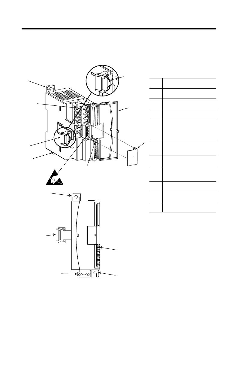
Description
1a
9
Item Description
1a upper panel mounting tab
7
3
1b lower panel mo unting tab
2I/O diagnostic LEDs
3 module door with
terminal identification
label
5
6
1b
4
2
4 bus connector
with male pins
5 bus connector cover
6 flat ribbon cable with bus
connector ( female pins)
7 terminal block
1a
8 DIN rail latch
9 pull loop
6
2
8
1b
1762-IN004A-US-P
Page 4
4 MicroLogix™ 1762-IQ8 DC Input Module
Installation
1762 I/O is suitable for use in an industrial environment whe n installed in
accord an ce with the se in struction s . Sp e ci fic ally, this equipm en t is in tended for
use in clean, dry environments ( Po llution degre e 2
exceeding Over Vo ltage Cat egory II
(2)
(IEC 60664-1).
Prevent Electrostatic Discharge
(1)
) and to circuits not
(3)
!
Remove Power
!
ATTENTION:
circuits or semiconductors if you touch bus connector pins.
Follow these guidelines when you handle the module:
Touch a grounded objec t to discharge static potential.
•
Wear an approved wris t-strap grounding de vice.
•
Do not touch the bus connector or connector pins.
•
Do not touch circuit components inside the module.
•
If av ailabl e, use a static-safe work sta tion.
•
When not in use, keep the module in its static-shield box.
•
ATTENTION:
this module. When you remove or install a mo dule with power
applied, an electrical arc may occur. An electrical arc can cause
personal injury or property damage by:
sending an erroneous signal to your system’s field devices ,
•
causing unint ended machine motion
causing an explosion in a hazardous environment
•
causing permanent damage to the module’s circuitry
•
Electrical arcing causes excessive wear to contacts on both the
module and its mating connector. Worn contacts may cre ate
electri cal resistan c e .
Electrostatic discharge can damage integrated
Remove po wer before removing or inst alling
(1)
Pollution Degree 2 is an environment where, normally, only non-conductive pollution occurs except that
occasionally a temporary conductivity caused by condensation shall be expected.
(2)
Over Voltage C ateg ory II i s the l oad level se ct ion of t he electri c al d istribu ti on sys tem. A t th is lev el tr ans ien t
voltages are controlled and do not exceed the impulse voltage capability of the product’s insulation.
(3)
Pollution Degree 2 and Over Voltage Category II are International Electrotechnical Commission (IEC)
designations.
1762-IN004A-US-P
Page 5
MicroLogix™ 1762-IQ8 DC Input Module 5
Mounting
ATTENTION:
the module and a ll other e qui pment near t he mo dule is mou nted a nd
!
wiring is complete. Once wiring is complete and the module is free
of debris, carefully remove protective debris strip. Failure to
remove strip before operating can cause overheating.
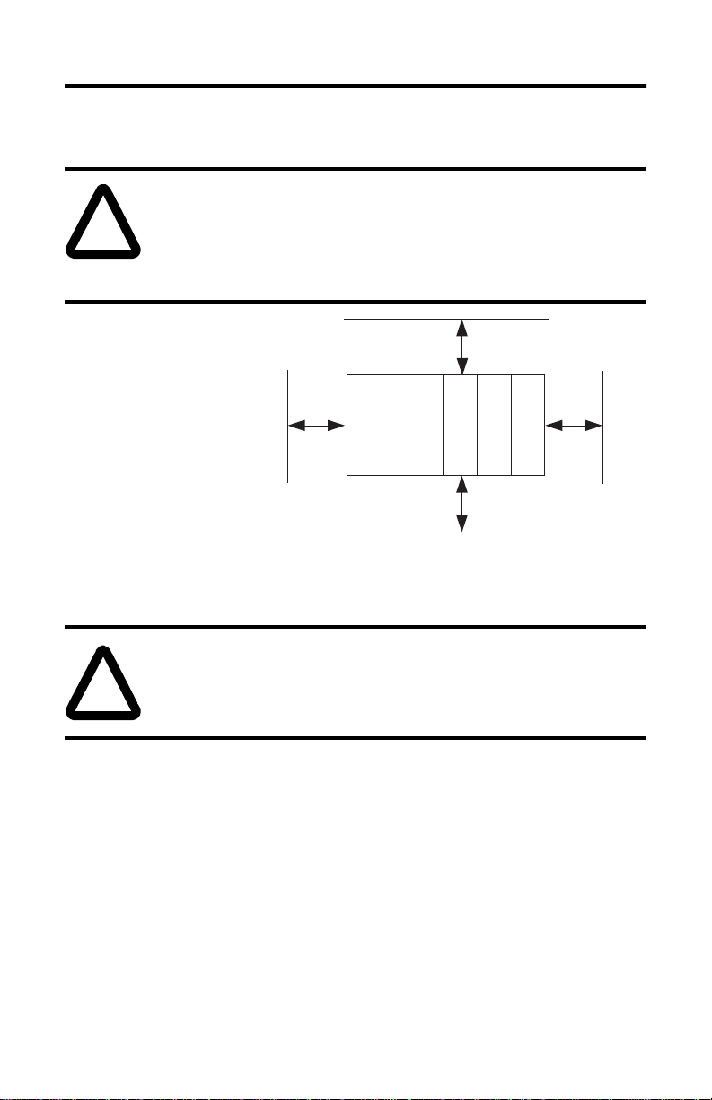
Minimum Spacing
Main ta in s p ac ing from
enclosure walls,
wireways, adjacent
equipment, etc. Allow
50.8 mm (2 in.) of space
on all side s for ad eq u at e
ventilation, as sho wn:
Note:
1762 expansion I/O ma y be mounted horizontally onl y.
A TT ENTION:
be sure that all debris (metal chips, wire strands, etc.) is kept from
!
falling into the module. Debris that falls into the module could
cause damage when power is applied to the module.
Do not remove protective debris strip until after
Top
Side Side
During panel or DIN rail mounting of all devices,
MicroLogix
1200
1762 I/O
1762 I/O
Bottom
1762 I/O
1762-IN004A-US-P
Page 6

6 MicroLogix™ 1762-IQ8 DC Input Module
DIN Rail Mounting
The module can be mounted us ing the following DIN rails: 35 x 7.5 mm
(EN 50 022 - 35 x 7.5) or 35 x 15 mm (EN 50 022 - 35 x 15).
Before mounting the module on a DIN rail, close the DIN rail latch. P res s the
DIN rail mounting area of the module against the DIN rail. T he latch will
momentarily open and lock into place.
Use DIN rail end anchors (Allen-Bradley part number 1492-EA35 or
1492-EAH35) for vibrati on or s hock environments .
End Anchor
End Anchor
Note:
For environ ments with greater vibration and shock conc erns , use the
panel mounting method described below, instead of DIN rail
mounting.
Panel Mounting
Use the dimensional template show n below to mount the module. The preferred
mounting method is to use two M4 or #8 pa nhead s cre ws per modul e. M3.5 or #6
panhead screws may also be used, but a washer may be needed to ensure a good
ground contact. Mounting screws are required on every module.
For more than 2 modules: (number of modules - 1) x 40 mm (1.58 in.)
100
90
(3.94)
(3.54)
1762-IN004A-US-P
14.5
(0.57)
ControllerController
MicroLogix 1200 MicroLogix 1200
40.4
(1.59)
Expansion I/OExpansion I/O
MicroLogix 1200 MicroLogix 1200
MicroLogix 1200 MicroLogix 1200
40.4
(1.59)
NOTE: All dimensions
are in mm (inches).
Hole spacing
tolerance: ±0.4 mm
Expansion I/OExpansion I/O
Expansion I/OExpansion I/O
MicroLogix 1200 MicroLogix 1200
(0.016 in.).
Page 7

MicroLogix™ 1762-IQ8 DC Input Module 7
System Assembly
The expansi on I/O module is attache d to the controller or ano ther I/O module by
means of a flat ribbon cable
mounting as sho w n below.
after
Note:
Use the pull loop on the connector to disconnect modules. Do not pull
on the ribbon cable.
ATTENTION:
In Class I, Division 2 applications, the bus connector must be
!
•
fully seated and the bus connector cover must be snapped in
place.
In Class I, Division 2 appli cations, al l modules must be mounted
•
in direct contact with each other as shown on page 6. If DIN rail
mounting is used, an end stop must be installed ahead of the
controller and after the last 1762 I/O module.
EXPLOSION HAZARD
Field Wiring Connections
Grounding the Module
This product is intended to be mounted to a well-grounded mounting surface
such as a metal panel. Additional grounding connections from the module’s
mounting tabs or DIN rail (if used) are not required unless the mounting surface
cannot be grounded. Refer to
Guidelines
, Allen-Bradle y publication 1770-4.1, for additional information.
Industria l Automation Wiring and Grounding
1762-IN004A-US-P
Page 8

8 MicroLogix™ 1762-IQ8 DC Input Module
Input Wiring
Basic wiring
A write-on label is provided with the modul e. Mark the identification of each
terminal with permanent ink, and slide the label back into the door.
(1)
of input devices to the 1762-IQ8 is shown below.
+DC (sinking)
-DC (sourcing)
IN 0
IN 2
IN 4
IN 6
-DC (sinking)
+DC (sourcing)
IN 1
IN 3
24V dc
IN 5
IN 7
DC
COM
DC
COM
Commons are
connected internally.
ATTENTION:
Be careful when stripping wires. Wire fragments
that fall into a mo dule could cause damage when po wer is applied.
!
Once wiring is com p lete, ensur e the module is fre e of all metal
fragments.
ATTENTION:
Miswiring of the module to an AC power source
will damage the module.
!
(1)
Sinking/Sourcing Inputs - Sourcing/sinking describes the current flow between the I/O module and the
field device. Sourcing I/O circuits supply (sourc e) current to sinking field devices. Sinking I / O circuits are
driven by a current sourcing field device. Field devices connected to the negative side (DC Common) of
the field power supply are sinking field devices. Fi eld devices connected to the posit ive side (+ V) of the
field supply are sourcing field devices.
1762-IN004A-US-P
Page 9

MicroLogix™ 1762-IQ8 DC Input Module 9
Note: Fi nger-safe cover not sho wn.
Wiring the Finger-Safe Terminal Block
When wiring the terminal block, keep the finger-safe cover in place.
Route the wire under the termina l pressure plate . You can use the strippe d end
1.
of the wire or a spade lug. The termi nals will accept a 6.35 mm (0.25 in.)
spade lug.
Tighten th e te r m i n al scr ew ma k i n g su r e th e pr essure plate s ec u re s the w ir e .
2.
Recommended torque whe n tightening terminal s crews is 0.904 Nm
(8 in-lbs).
Note:
If you need to remove the finger-safe cover, insert a screw driver into
one of the square wiring holes and gently pry the cover off. If you wire
the terminal bloc k with the finger-s afe cover removed, you will not be
able to put it back on the t erm inal block beca use the wires will be in the
way.
Wire Size and Terminal Screw Torque
Each termi nal accepts up to two wires with th e f ollowin g restrictions:
Wire Type Wire Size Terminal Screw Torque
Solid Cu-90°C (194°F) #14 to #22 AWG 0.904 Nm (8 in-lbs)
Stranded Cu-90°C (194°F) #16 to #22 AWG 0.904 Nm (8 in-lbs)
1762-IN004A-US-P
Page 10

10 MicroLogix™ 1762-IQ8 DC Input Module
I/O Memory Mapping
Input Data File
For each input mo dule, the input data f ile contains the curre nt state of the field
input points. Bit positions 0 through 7 correspond to input terminals 0 through 7.
Bit Position
1514131211109876543210
Word
000000000rrrrrrrr
r = read only, 0 = always at a 0 or OFF state
Addressing
The addressing scheme for 1762 Expansion I/O is shown below.
Slot Number
Data File
(1)
Word (always zero for this module)
Input
Bit (0 - 7)
I1:x.0/0
Slot Delimiter
(1) I/O located on the controller (embedded I/O) is slot 0. I/O added to the controller (expansion I/O) begins
with slot 1.
1762-IN004A-US-P
Word Delimiter
Bit Delimiter
Page 11

MicroLogix™ 1762-IQ8 DC Input Module 11
Specifications
General Specifications
Specification Value
Dimensions 90 mm (height) x 87 mm (depth) x 40 mm (width)
Approximate Shipping Weight
(with carton)
Storage Temperature -40°C to +85°C (-40°F to +185°F)
Operating Temperature 0°C to +55°C (-32°F to +131°F)
Operating Humidity 5% to 95% non-condensing
Operating Altitude 2000 meters (6561 feet)
Vibration Operating: 10 to 500 Hz, 5G, 0.030 in. max. peak-to-peak
Shock Operating : 30G panel mounted
Agency Certification C-UL certified (under CSA C22.2 No. 142)
Hazardous Environment Class Class I, Division 2, Hazardous Location, Groups A, B, C, D
Noise Immunity NEMA standa rd ICS 2-230
Radiated and Conducted Emissions EN50081-2 Class A
Electrica l /EMC: The module has passed testing at the following levels:
ESD Immunity (IEC1000-4-2) 4 kV contact, 8 kV air, 4 kV indirect
Radiated Immunity (IEC1000-4-3) 10 V/m, 80 to 1000 MHz, 80% amplitude modulation,
Fast Transient Burst (IEC1000-4-4) 2 kV, 5 kHz
Surge Immunity (IEC1000-4-5) 2 kV common mode, 1 kV differential mode
Conducted Immunity (IEC1000-4-6)
(1)
Conducted Immunity frequency range may be 150 kHz to 30 MHz if the Radiated Immunity frequency
range is 30 MHz to 1000 MHz.
height including mounting tabs is 110 mm
3.543 in. (height) x 3.425 in. (depth) x 1.575 in. (width)
height including mounting tabs is 4.33 in.
200 g (0.44 lbs.)
UL 508 listed
CE compliant for all applicable directives
(UL 1604, C-UL under CSA C22.2 No. 213)
+900 MHz keyed carrier
10V, 0.15 to 80 MHz
(1)
1762-IN004A-US-P
Page 12

12 MicroLogix™ 1762-IQ8 DC Input Module
Input Specifications
Specification 1762-IQ8
Voltage Category
24V dc (sink/source)
Operating Voltage Range 10 to 30V dc at 30°C (86°F)
10 to 26.4V dc at 55°C (131°F)
Number of Inputs 8
Bus Current Draw (max.) 50 mA at 5V dc (0.25W)
Hea t Dissipation (max.) 3.7 Total Watts
Signal Delay (max.) On Delay: 8.0 ms
Off Delay: 8.0 ms
Off-State Voltage (max.) 5V dc
Off-State Current (max.) 1.5 mA
On-State Voltage (min.) 10V dc
On-State Current 2.0 mA min. at 10V dc
8.0 mA nominal at 24V dc
12.0 mA max. at 30V dc
Inrush Current (max.) 250 mA
Nominal Impedance 3K Ω
IEC Input Compatibility Type 1+
Power Supply Dist ance Rating 6
Isolated Groups Group 1: inputs 0 to 7 (internally connected commons)
Input Group to Backplane
Isolation
Verified by one of the following dielectric tests: 1200V ac for 1
sec. or 1697V dc for 1 sec.
75V dc working voltage (IEC Class 2 reinforced insulation)
Vendor I.D. Code 1
Product Type Co de 7
Product Code 96
(1)
Sinking/Sourcing Inputs - Sourcing/sinking describes the current flow between the I/O module and the
field device. Sourcing I/O circuits supply (sourc e) current to sinking field devices. Sinking I / O circuits are
driven by a current sourcing field device. Field devices connected to the negative side (DC Common) of
the field power supply are sinking field devices. Fi eld devices connected to the posit ive side (+ V) of the
field supply are sourcing field devices.
(1)
1762-IN004A-US-P
Page 13

MicroLogix™ 1762-IQ8 DC Input Module 13
Hazardous Location Considerations
This equipment is suitable for use in Clas s I, Division 2, Groups A, B, C, D or
non-hazardous locations only. The following ATTENTION statement applies to
use in hazardous locations.
ATTENTION:
Substitution of components may impair suitability for Class I,
!
•
Division 2.
Do not replace components or disconnect equipment unless
•
power has been switc hed off.
Do not connect or disconnect components unless power has
•
been switched off.
This product must be ins talled in an enclosure.
•
In Class I, Division 2 applications, the bus connector must be
•
fully seated and the bus connector cover must be snapped in
place.
In Class I, Division 2 applications, all modules must be
•
mounted in direct contact with each other as sho wn on page 6.
If DIN rail mounting is used, an end stop must be installed
ahead of the controller and after the last 1762 I/O module.
EXPLOSION HAZARD
1762-IN004A-US-P
Page 14

14 MicroLogix™ 1762-IQ8 DC Input Module
Environnements dangereux
Cet équipement est conçu pour être util isé dans des environnements de Clas se I,
Division 2, Groupes A, B, C, D ou non dangereux. La mise en garde suivante
s’applique à une utilisation dans des environnements dangereux.
ATTENTION:
La substituti on de composants peut rendre cet équipement
!
•
impropre à une utilisation en environnement de Classe I,
Division 2.
Ne pas remplacer de composants ou déconnecter l'équipement
•
sans s'être assu ré que l'alimentation est coupée.
Ne pas connecter ou déconnecter des composants sans s'ê tre
•
assuré que l'alimentation est coupée.
Ce produit doit être installé dans une armoire.
•
Pour les applications de Classe I, Div ision 2, le connecteur de
•
bus doi t être corr ectement installé et son cou vercle en clench é.
Pour les applications de Classe I, Division 2, tous les modules
•
doivent être installés en contact direct les uns avec les autres,
comme indiqué page 6. Si on utilise le montage sur ra il DIN,
une butée doit être placée à l'avant de l'automate et après la
dernière unité d'E/S 1762.
DANGER D’EXPLOSION
1762-IN004A-US-P
Page 15

MicroLogix™ 1762-IQ8 DC Input Module 15
1762-IN004A-US-P
Page 16

MicroLogix is a trademark of Rockwell Automation.
Publication 1762-IN004A-US-P September 1999 PN 40071-071-01(A)
© (1999) Rockwell International Corporation. Printed in the U.S.A.
´H'*g!¶Ai¨
 Loading...