

Page 1
Installation Instructions
MicroLogix 1762-IF2OF2 Analog Input/Output
Module
Catalog Number 1762-IF2OF2
Topic Page
Important User Information 2
North American Hazardous Location Approval 4
Additional Resources 5
Overview 6
Module Description 7
Mount the Module 8
Field Wiring Connections 11
Wiring 13
Sensor/Transmitter Types 15
I/O Memory Mapping 17
Input Data File 17
Output Data File 18
Configuration Data File 19
Specifications 21
Page 2
2 MicroLogix 1762-IF2OF2 Analog Input/Output Module
WARNING
IMPORTANT
ATTENTION
SHOCK HAZARD
BURN HAZARD
Important User Information
Solid state equipment has operational characteristics differing from those of electromechanical equipment.
Safety Guidelines for the Application, Installation and Maintenance of Solid State Controls (Publication
SGI-1.1
available from your local Rockwell Automation sales office or online at
http://literature.rockwellautomation.com
equipment and hard-wired electromechanical devices. Because of this difference, and also because of the
wide variety of uses for solid state equipment, all persons responsible for applying this equipment must
satisfy themselves that each intended application of this equipment is acceptable.
In no event will Rockwell Automation, Inc. be responsible or liable for indirect or consequential damages
resulting from the use or application of this equipment.
The examples and diagrams in this manual are included solely for illustrative purposes. Because of the many
variables and requirements associated with any particular installation, Rockwell Automation, Inc. cannot
assume responsibility or liability for actual use based on the examples and diagrams.
No patent liability is assumed by Rockwell Automation, Inc. with respect to use of information, circuits,
equipment, or software described in this manual.
Reproduction of the contents of this manual, in whole or in part, without written permission of Rockwell
Automation, Inc., is prohibited.
Throughout this manual, when necessary, we use notes to make you aware of safety considerations.
Identifies information about practices or circumstances that can cause an explosion in
a hazardous environment, which may lead to personal injury or death, property
damage, or economic loss.
) describes some important differences between solid state
Publication 1762-IN005C-EN-P - July 2013
Identifies information that is critical for successful application and understanding of
the product.
Identifies information about practices or circumstances that can lead to personal injury
or death, property damage, or economic loss. Attentions help you identify a hazard,
avoid a hazard and recognize the consequences.
Labels may be on or inside the equipment (for example, drive or motor) to alert people
that dangerous voltage may be present.
Labels may be on or inside the equipment (for example, drive or motor) to alert people
that surfaces may reach dangerous temperatures.
Page 3
MicroLogix 1762-IF2OF2 Analog Input/Output Module 3
ATTENTION
ATTENTION
Environment and Enclosure
This equipment is intended for use in a Pollution Degree 2 industrial
environment, in overvoltage Category II applications (as defined in IEC 60664-1),
at altitudes up to 2000 m (6562 ft) without derating.This equipment is
considered Group 1, Class A industrial equipment according to IEC/CISPR 11.
Without appropriate precautions, there may be difficulties with electromagnetic
compatibility in residential and other environments due to conducted and
radiated disturbances.
This equipment is supplied as open-type equipment. It must be mounted within
an enclosure that is suitably designed for those specific environmental
conditions that will be present and appropriately designed to prevent personal
injury resulting from accessibility to live parts. The enclosure must have suitable
flame-retardant properties to prevent or minimize the spread of flame,
complying with a flame spread rating of 5VA, V2, V1, V0 (or equivalent) if
non-metallic. The interior of the enclosure must be accessible only by the use of
a tool. Subsequent sections of this publication may contain additional
information regarding specific enclosure type ratings that are required to comply
with certain product safety certifications.
In addition to this publication, see:
• Industrial Automation Wiring and Grounding Guidelines, for additional
installation requirements, Allen-Bradley publication 1770-4.1
• NEMA Standards 250 and IEC 60529, as applicable, for explanations of
the degrees of protection provided by different types of enclosure.
.
Preventing Electrostatic Discharge
This equipment is sensitive to electrostatic discharge, which can cause internal
damage and affect normal operation. Follow these guidelines when you handle
this equipment:
• Touch a grounded object to discharge potential static.
• Wear an approved grounding wriststrap.
• Do not touch connectors or pins on component boards.
• Do not touch circuit components inside the equipment.
• Use a static-safe workstation, if available.
• Store the equipment in appropriate static-safe packaging when not in use.
Publication 1762-IN005C-EN-P - July 2013
Page 4
4 MicroLogix 1762-IF2OF2 Analog Input/Output Module
WARNING
AVERTISSEMENT
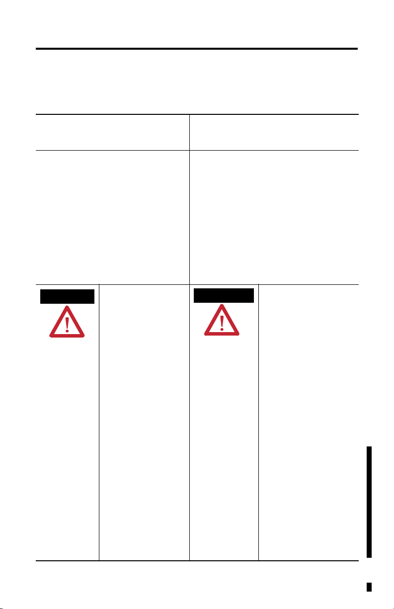
North American Hazardous Location Approval
The following modules are North American Hazardous Location approved: 1762-IF2OF2
The following information applies when
operating this equipment in hazardous
locations:
Products marked "CL I, DIV 2, GP A, B, C, D" are
suitable for use in Class I Division 2 Groups A, B, C,
D, Hazardous Locations and nonhazardous
locations only. Each product is supplied with
markings on the rating nameplate indicating the
hazardous location temperature code. When
combining products within a system, the most
adverse temperature code (lowest "T" number) may
be used to help determine the overall temperature
code of the system. Combinations of equipment in
your system are subject to investigation by the
local Authority Having Jurisdiction at the time of
installation.
EXPLOSION HAZARD
• Do not disconnect equipment
unless power has been removed
or the area is known to be
nonhazardous.
• Do not disconnect connections to
this equipment unless power has
been removed or the area is
known to be nonhazardous.
Secure any external connections
that mate to this equipment by
using screws, sliding latches,
threaded connectors, or other
means provided with this product.
• Substitution of components may
impair suitability for Class I,
Division 2.
• If this product contains batteries,
they must only be changed in an
area known to be nonhazardous.
• All wiring must comply with
N.E.C. article 501-4(b).
• The interior of the enclosure must
be accessible only by the use of a
tool.
• For applicable equipment (relay
modules, etc.), exposure to some
chemicals may degrade the
sealing properties of materials
used in the following devices:
Relays, Epoxy. It is recommended
that the User periodically inspect
these devices for any degradation
of properties and replace the
module if degradation is found.
Informations sur l’utilisation de cet
équipement en environnements dangereux:
Les produits marqués "CL I, DIV 2, GP A, B, C, D" ne
conviennent qu'à une utilisation en environnements de
Classe I Division 2 Groupes A, B, C, D dangereux et non
dangereux. Chaque produit est livré avec des
marquages sur sa plaque d'identification qui indiquent
le code de température pour les environnements
dangereux. Lorsque plusieurs produits sont combinés
dans un système, le code de température le plus
défavorable (code de température le plus faible) peut
être utilisé pour déterminer le code de température
global du système. Les combinaisons d'équipements
dans le système sont sujettes à inspection par les
autorités locales qualifiées au moment de l'installation.
RISQUE D’EXPLOSION
• Couper le courant ou s’assurer que
l’environnement est classé non
dangereux avant de débrancher
l'équipement.
• Couper le courant ou s'assurer que
l'environnement est classé non
dangereux avant de débrancher les
connecteurs. Fixer tous les
connecteurs externes reliés à cet
équipement à l'aide de vis, loquets
coulissants, connecteurs filetés ou
autres moyens fournis avec ce
produit.
• La substitution de composants peut
rendre cet équipement inadapté à une
utilisation en environnement de
Classe I, Division 2.
• S’assurer que l’environnement est
classé non dangereux avant de
changer les piles.
Publication 1762-IN005C-EN-P - July 2013
Page 5

MicroLogix 1762-IF2OF2 Analog Input/Output Module 5
Additional Resources
Resource Description
MicroLogix 1100 Programmable Controllers User
Manual, publication 1763-UM001
MicroLogix 1200 Programmable Controllers User
Manual, publication 1762-UM001
MicroLogix 1400 Programmable Controllers User
Manual, publication 1766-UM001
MicroLogix 1100 Programmable Controllers
Installation Instructions, publication 1763-IN001
MicroLogix 1200 Programmable Controllers
Installation Instructions, publication 1762-IN006
MicroLogix 1400 Programmable Controllers
Installation Instructions, publication 1766-IN001
Industrial Automation Wiring and Grounding
Guidelines, publication 1770-4.1
.
.
.
.
A more detailed description of how to install and use
your MicroLogix 1100 programmable controller and
expansion I/O system.
A more detailed description of how to install and use
your MicroLogix 1200 programmable controller and
expansion I/O system.
A more detailed description of how to install and use
your MicroLogix 1400 programmable controller and
expansion I/O system.
Information on installing and using the MicroLogix
.
1100 programmable controller.
Information on installing and using the MicroLogix
.
1200 programmable controller.
Information on installing and using the MicroLogix
.
1400 programmable controller.
More information on proper wiring and grounding
techniques.
If you would like a manual, you can:
• download a free electronic version from the Internet:
http://literature.rockwellautomation.com
• purchase a printed manual by contacting your local Allen-Bradley distributor or
Rockwell Automation representative
Publication 1762-IN005C-EN-P - July 2013
Page 6
6 MicroLogix 1762-IF2OF2 Analog Input/Output Module
ATTENTION
ATTENTION
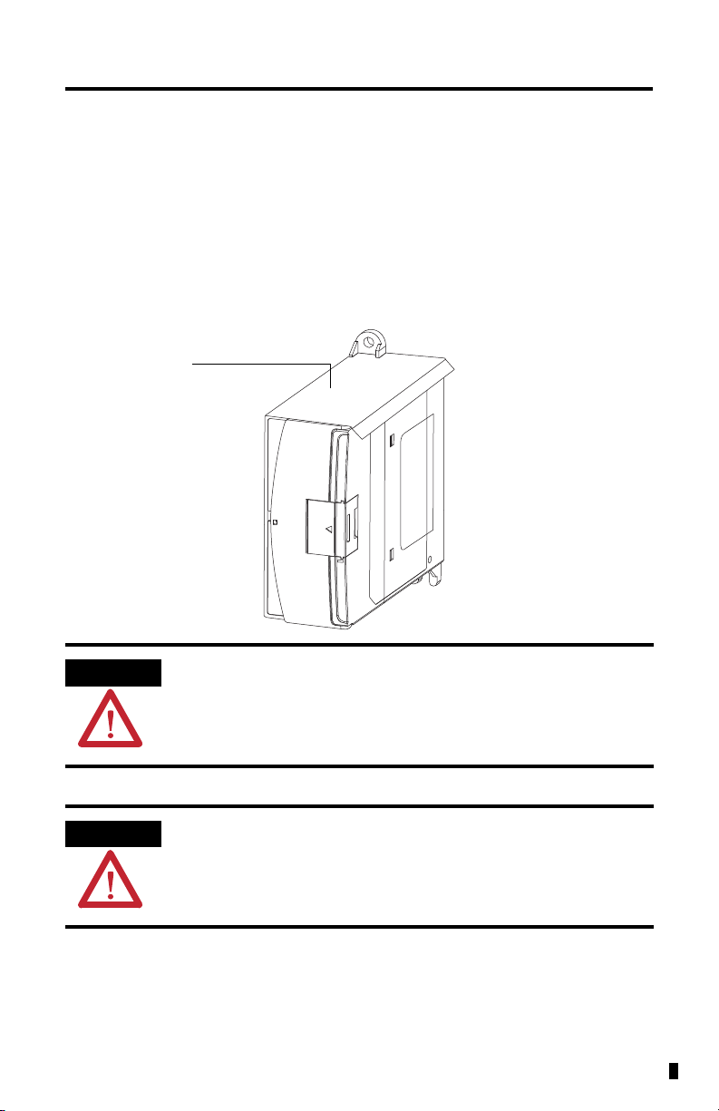
Debris strip
45155
Overview
The 1762 input module is suitable for use in an industrial environment when installed in
accordance with these instructions. Specifically, this equipment is intended for use in clean, dry
environments (Pollution degree 2
(3)
(IEC 60664-1)
.
Install your module using these installation instructions.
1762 Analog Input/Output Module
(1)
) and to circuits not exceeding Over Voltage Category II
(2)
(1)
(2)
(3)
Publication 1762-IN005C-EN-P - July 2013
Do not remove the protective debris strip until after the module and all other
equipment in the panel near the module are mounted and wiring is complete.
Once wiring is complete, remove protective debris strip. Failure to remove strip
before operating can cause overheating.
Electrostatic discharge can damage semiconductor devices inside the module.
Do not touch the connector pins or other sensitive areas.
Pollution Degree 2 is an environment where, normally, only non-conductive pollution occurs except that occasionally a
temporary conductivity caused by condensation shall be expected.
Over Voltage Category II is the load level section of the electrical distribution system. At this level transient voltages are
controlled and do not exceed the impulse voltage capability of the product’s insulation.
Pollution Degree 2 and Over Voltage Category II are International Electrotechnical Commission (IEC) designations.
Page 7
MicroLogix 1762-IF2OF2 Analog Input/Output Module 7
ATTENTION
1a
4
8
9
7
3
10
5
6
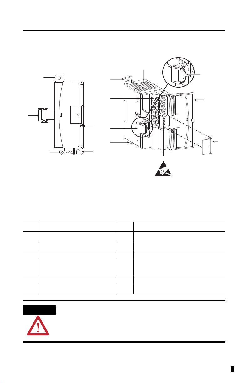
Left side viewFront view
This equipment is sensitive to electrostatic discharge (ESD).
Follow ESD prevention guidelines when handling this equipment.
45157
1a
1b
3
4
2
45156
Module Description
Item Description Item Description
1a upper panel mounting tab 6 pull loop
1b lower panel mounting tab 7 module door with terminal identification label
2 power diagnostic LED 8 bus connector cover
3 flat ribbon cable with bus connector
(female)
5 input type selector switch
4 DIN rail latch 10 terminal block
9 bus connector
with male pins
To comply with UL restrictions, this equipment must be powered from a source
compliant with Class 2 or Limited Voltage/Current.
Publication 1762-IN005C-EN-P - July 2013
Page 8
8 MicroLogix 1762-IF2OF2 Analog Input/Output Module
ATTENTION
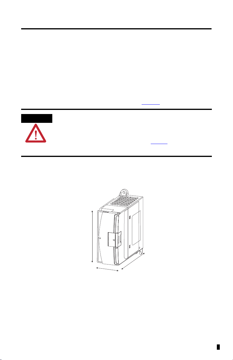
Measurements do not include mounting feet or DIN rail latches.
90 mm
(3.5 in.)
87 mm
(3.43 in.)
40.4 mm (1.59 in.)
45158
Mount the Module
General Considerations
Most applications require installation in an industrial enclosure to reduce the effects of electrical
interference and environmental exposure. Locate your controller as far as possible from power
lines, load lines, and other sources of electrical noise such as hard-contact switches, relays, and
AC motor drives. For more information on proper grounding guidelines, see the Industrial
Automation Wiring and Grounding Guidelines, publication 1770-4.1
This product is intended to be mounted to a well-grounded mounting surface
such as a metal panel. Additional grounding connections from the power
supply's mounting tabs or DIN rail (if used) are not required unless the mounting
surface cannot be grounded. Refer to Industrial Automation Wiring and
Grounding Guidelines, Allen-Bradley publication 1770-4.1
information.
Mounting Dimensions
.
, for additional
Publication 1762-IN005C-EN-P - July 2013
Page 9
MicroLogix 1762-IF2OF2 Analog Input/Output Module 9
TIP
Top
Bottom
Side
44913
Side
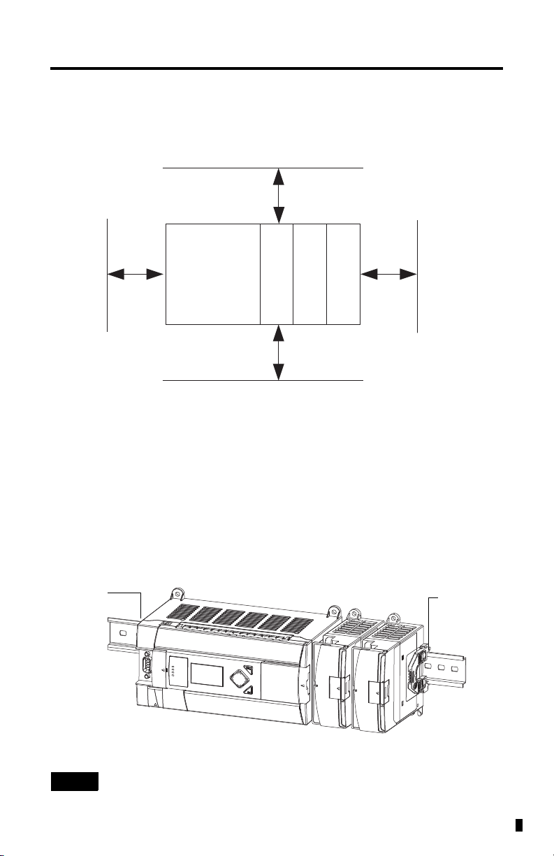
End anchor
End anchor
45159
Module Spacing
Maintain spacing from objects such as enclosure walls, wireways and adjacent equipment. Allow
50.8 mm (2 in.) of space on all sides for adequate ventilation, as shown:
MicroLogix
1100/1200/1400
1762 I/O
1762 I/O
1762 I/O
DIN Rail Mounting
The module can be mounted using the following DIN rails: 35 x 7.5 mm (EN 50 022 - 35 x 7.5)
or 35 x 15 mm (EN 50 022 - 35 x 15).
Before mounting the module on a DIN rail, close the DIN rail latch. Press the DIN rail
mounting area of the module against the DIN rail. The latch will momentarily open and lock
into place.
Use DIN rail end anchors (Allen-Bradley part number 1492-EA35 or 1492-EAH35) for
vibration or shock environments.
For environments with greater vibration and shock concerns, use the panel
mounting method described below, instead of DIN rail mounting.
Publication 1762-IN005C-EN-P - July 2013
Page 10

10 MicroLogix 1762-IF2OF2 Analog Input/Output Module
TIP
90
(3.54)
100.06
(3.939)
40.4
(1.59)
40.4
(1.59)
14.2
(0.568)
MicroLogix
1100/1200/1400
1762 I/O
1762 I/O
1762 I/O
95 (3.74)
44914
For more than two I/O modules: measure (number of modules - 1) x 40 mm (1.59 in.)
NOTE: All dimensions are in mm (in.). Hole spacing tolerance: ±0.4 mm (0.016 in.).
Bus connector covers
1762 expansion
bus connector
cover
45160
Panel Mounting
Use the dimensional template shown below to mount the module. The preferred mounting
method is to use two M4 (#8) panhead screws per module. M3.5 (#6) panhead screws may also
be used, but a washer may be needed to ensure a good mechanical contact. Mounting screws are
required on every module.
System Assembly
The expansion I/O module is attached to the controller or another I/O module by means of a
flat ribbon cable after mounting as shown below.
Publication 1762-IN005C-EN-P - July 2013
Use the pull loop on the connector to disconnect modules. Do not pull on the
ribbon cable.
Page 11

MicroLogix 1762-IF2OF2 Analog Input/Output Module 11
WARNING
ATTENTION
WARNING
Field Wiring Connections
Grounding the Module
In solid-state control systems, grounding and wire routing helps limit the effects of noise due to
electromagnetic interference (EMI). Run the ground connection from the ground screw of the
controller to the ground bus prior to connecting any devices. Use AWG #14 wire. For
AC-powered controllers, this connection must be made for safety purposes.
You must also provide an acceptable grounding path for each device in your application. For
more information on proper grounding guidelines, refer to the Industrial Automation Wiring
and Grounding Guidelines, publication 1770-4.1
EXPLOSION HAZARD
• In Class I, Division 2 applications, the bus connector must be fully seated and
the bus connector cover must be snapped in place.
• In Class I, Division 2 applications, all modules must be mounted in direct
contact with each other as shown on page 10. If DIN rail mounting is used, an
end anchor must be installed ahead of the controller and after the last 1762
I/O module.
.
To comply with the CE Low Voltage Directive (LVD), all connected I/O must be
powered from a source compliant with the Safety Extra Low Voltage (SELV) or
Protected Extra Low Voltage (PELV).
If you connect or disconnect wiring while the field-side power is on, an electrical
arc can occur. This could cause an explosion in hazardous location installations.
Be sure that power is removed or the area is nonhazardous before proceeding.
Publication 1762-IN005C-EN-P - July 2013
Page 12

12 MicroLogix 1762-IF2OF2 Analog Input/Output Module
1
ON
2
Current (ON) Default
Voltage (OFF)
Switch 1 = Channel 0
Switch 2 = Channel 1
Switch Location
45162
Input Type Selection
Select the input type, current or voltage, using the switch located on the module’s circuit board
and the input type/range selection bits in the Configuration Data File (seeConfiguration Data
File on page 19). You can access the switch through the ventilation slots on the top of the
module. Switch 1 controls channel 0; switch 2 controls channel 1. The factory default setting for
both switch 1 and switch 2 is Current. Switch positions are shown below.
Output Type Selection
The output type selection, current or voltage, is made by wiring to the appropriate terminals,
Iout or Vout, and by the type/range selection bits in the Configuration Data File
(seeConfiguration Data File
Publication 1762-IN005C-EN-P - July 2013
on page 19 ).
Page 13

MicroLogix 1762-IF2OF2 Analog Input/Output Module 13
ATTENTION
V out 1
V out 0
IN 1 +
IN 0 +
I out 1
I out 0
IN 1 -
IN 0 -
COM
COM
Commons connected
internally
Wiring
System Wiring Guidelines
Consider the following when wiring your system:
• The analog common (COM) is not connected to earth ground inside the module. All
terminals are electrically isolated from the system.
• Channels are not isolated from each other.
• Use Belden 8761, or equivalent, shielded wire.
• Under normal conditions, the drain wire (shield) should be connected to the metal
mounting panel (earth ground). Keep shield connection to earth ground as short as
possible.
• To ensure optimum accuracy for voltage type inputs and outputs, limit overall cable
impedance by keeping all analog cables as short as possible. Locate the I/O system as
close to your voltage type sensors or actuators as possible.
• The 1762-IF2OF2 module does not provide loop power for analog inputs. Use a power
supply that matches the input transmitter specifications.
Terminal Block Layout
Analog outputs may fluctuate for less than a second when power is applied or
removed. This characteristic is common to most analog outputs. While the
majority of loads will not recognize this short signal, it is recommended that
preventive measures be taken to ensure that connected equipment is not
affected.
Publication 1762-IN005C-EN-P - July 2013
Page 14

14 MicroLogix 1762-IF2OF2 Analog Input/Output Module
TIP
IN 0 (+)
IN 0 (-)
V out 0
V out 1
I out 0
I out 1
COM
IN 1 (-)
IN 1 (+)
COM
Analog Sensor
Analog Load
Differential Sensor Transmitter Types
Grounding the cable shield at the module end only usually provides sufficient noise
immunity. However, for best cable shield performance, earth ground the shield at
both ends, using a 0.01µF capacitor at one end to block AC power ground currents, if
necessary.
Publication 1762-IN005C-EN-P - July 2013
Page 15

Sensor/Transmitter Types
+
+
-
-
+-+
-
IN +
IN COM
+
-
IN +
IN COM
+
-
IN +
IN COM
Power
Supply
(1
Power
Supply
(1)
Power
Supply
(1)
Transmitter
Transmitter
Transmitter
Module
Module
Module
Supply Signal
Supply Signal
2-Wire Transmitter
3-Wire Transmitter
4-Wire Transmitter
(1) All power supplies rated N.E.C. Class 2.
45161
MicroLogix 1762-IF2OF2 Analog Input/Output Module 15
Labeling the Terminals
A write-on label is provided with the module. Mark the identification of each terminal with
permanent ink, and slide the label back into the door.
Publication 1762-IN005C-EN-P - July 2013
Page 16

16 MicroLogix 1762-IF2OF2 Analog Input/Output Module
ATTENTION
TIP
Wiring the Finger-Safe Terminal Block
Be careful when stripping wires. Wire fragments that fall into a module could
cause damage when power is applied. Once wiring is complete, ensure the
module is free of all metal fragments.
When wiring the terminal block, keep the finger-safe cover in place.
1. Route the wire under the terminal pressure plate. You can use the stripped end of the
wire or a spade lug. The terminals will accept a 6.35 mm (0.25 in.) spade lug.
2. Tighten the terminal screw making sure the pressure plate secures the wire.
Recommended torque when tightening terminal screws is 0.904 Nm (8 lb-in.).
3. After wiring is complete, remove the debris shield.
If you need to remove the finger-safe cover, insert a screw driver into one of the
square wiring holes and gently pry the cover off. If you wire the terminal block with
the finger-safe cover removed, you will not be able to put it back on the terminal
block because the wires will be in the way.
Wire Size and Terminal Screw Torque
Each terminal accepts up to two wires with the following restrictions:
Wire Type Wire Size Terminal Screw Torque
Solid Cu-90 °C (194 °F) #14…22 AWG 0.904 Nm (8 lb-in.)
Stranded Cu-90 °C (194 °F) #16…22 AWG 0.904 Nm (8 lb-in.)
Publication 1762-IN005C-EN-P - July 2013
Page 17

MicroLogix 1762-IF2OF2 Analog Input/Output Module 17
X1:x.0/0
Slot number
(1)
Data file (0 or 1)
File Type
Input (I) or Output (O)
Slot delimiter
Word delimiter
Bit delimiter
Bit (0...15)
Word
(1)
I/O located on the controller (embedded I/O) is slot 0. I/O added to the controller (expansion I/O) begins with slot 1.
Data File # 0 = Output
Data File # 1 = Input
I/O Memory Mapping
1762 Expansion I/O Addressing
The addressing scheme for 1762 Expansion I/O is shown below.
Input Data File
For each module, slot x, words 0 and 1 contain the analog values of the inputs. The module can
be configured to use either raw/proportional data or scaled-for-PID data. The input data file for
each configuration is shown below.
Raw/Proportional Format
Bit Position
15 14 13 12 11 10 9 8 7 6 5 4 3 2 1 0
Word
0 0 Channel 0 Data 0…32760 0 0 0
1 0 Channel 1 Data 0…32760 0 0 0
2 reserved
3 reserved
4 reserved SO1SO0reserved SI1SI
5UI0OI0UI1OI1reserved UO0OO0UO1 OO1reserved
Publication 1762-IN005C-EN-P - July 2013
0
Page 18

18 MicroLogix 1762-IF2OF2 Analog Input/Output Module
Scaled-for-PID Format
Bit Position
15 14 13 12 11 10 9 8 7 6 5 4 3 2 1 0
Word
0 0 0 Channel 0 Data 0…16,380 0 0
1 0 0 Channel 1 Data 0…16,380 0 0
2 reserved
3 reserved
4 reserved SO1SO0reserved SI1SI
5UI0OI0UI1OI1reserved U00O00U0
1 O01
The bits are defined as follows:
• SIx = General status bits for input channels 0 and 1.
SOx = General status bits for output channels 0 and 1. This bit is set when an error
(over- or under-range) exists for that channel, or there is a general module hardware
error.
• OIx = Over-range flag bits for input channels 0 and 1.
OOx = Over-range flag bits for output channels 0 and 1. These bits can be used in the
control program for error detection.
• UIx = Under-range flag bits for input channels 0 and 1.
UOx = Under-range flag bits for output channels 0 and 1. These bits can be used in the
control program for error detection.
reserved
0
Output Data File
For each module, slot x, words 0 and 1 contain the channel output data.
Raw/Proportional Format
Bit Position
15 14 13 12 11 10 9 8 7 6 5 4 3 2 1 0
Word
0 0 Channel 0 Data 0…32,760 0 0 0
1 0 Channel 1 Data 0…32,760 0 0 0
Scaled-for-PID Format
Bit Position
15 14 13 12 11 10 9 8 7 6 5 4 3 2 1 0
Word
0 0 0 Channel 0 Data 0…16,380 0 0
1 0 0 Channel 1 Data 0…16,380 0 0
Publication 1762-IN005C-EN-P - July 2013
Page 19

MicroLogix 1762-IF2OF2 Analog Input/Output Module 19
Configuration Data File
The configuration of the format for analog inputs and outputs is made at going to run (GTR).
Changes made to the configuration file while in run mode have no effect.
The configuration table for analog inputs and outputs is shown in the table below.
Configuration Data File
Bit Position
15 14 13 12 11 10 9 8 7 6 5 4 3 2 1 0
Word
0
1 Data Format Input
2 reserved
3 reserved
4
5 Data Format Output
6 reserved
7 reserved
Data Format Input
Channel 0
Channel 1
reserved
Data Format Output
Channel 0
Channel 1
reserved
Type/Range Select Input
Channel 0
Type/Range Select Input
Channel 1
Type/Range Select
Output Channel 0
Type/Range Select
Output Channel 1
reserved
reserved
reserved
reserved
Bit 15 and Bits 7…0 - Reserved
These bits are reserved and are not checked by the module.
Data Format (Bits 14…12)
These bits indicate the format of the data as shown in the following table. Other combinations of
these bits are not supported and result in an error.
Bit Settings Data Format
14 13 12
0 0 0 Raw/Proportional
0 1 0 Scaled for PID
other Not Supported
Publication 1762-IN005C-EN-P - July 2013
Page 20

20 MicroLogix 1762-IF2OF2 Analog Input/Output Module
Type/Range Select (Bits 11…8)
These bits indicate the type and range as in the following table. Other combinations of these bits
are not supported and result in an error.
Bit Settings Data Format
11 10 9 8
0010Voltage Mode 0…10V DC
0011Current Mode 4…20 mA
other Not Supported
Configuration via RSLogix 500
This module can be configured using RSLogix 500 programming software, as shown below.
Publication 1762-IN005C-EN-P - July 2013
Page 21

MicroLogix 1762-IF2OF2 Analog Input/Output Module 21
Specifications
General Specifications
Attribute Value
Dimensions, HxWxD 90 x 40.4 x 87 mm (3.54 x 1.59 x 3.43 in.)
Height including mounting tabs is 110 mm (4.33 in)
Approximate Shipping Weight
(with carton)
Bus Current Draw (max.) 40 mA @ 5V DC
Analog Normal Operating Range Voltage: 0…10V DC
(1)
Full Scale
Analog Ranges
Resolution 12 bits (unipolar)
Repeatability
(2)
Input and Output Group to System
Isolation
Module Power LED On: indicates power is applied.
Vendor ID Code 1
Product Type Code 10
Product Code 75
Recommended Cable Belden 8761 (shielded)
Wire size See Wire Size and Terminal Screw Torque
Wiring category
(1)
The over- or under-range flag comes on when the normal operating range (over/under) is exceeded. The module continues to
convert the analog input up to the maximum full scale range.
(2)
Repeatability is the ability of the input module to register the same reading in successive measurements for the same input
signal.
(3)
Rated working voltage is the maximum continuous voltage that can be applied at the terminals with respect to earth
ground.
(4)
Use this Conductor Category information for planning conductor routing. Refer to Industrial Automation Wiring and
Grounding Guidelines, publication 1770-4.1
(4)
240g (0.53 lbs.)
105 mA @ 24V DC
Current: 4…20 mA
Voltage: 0…10.5V DC
Current: 0…21 mA
±0.12%
30V AC/30V DC rated working voltage
(3)
(IEC Class 2 reinforced insulation)
type test: 500V AC or 707V DC for 1 minute
2 - on signal ports
.
on page 16
Publication 1762-IN005C-EN-P - July 2013
Page 22

22 MicroLogix 1762-IF2OF2 Analog Input/Output Module
Input Specifications
Attribute Value
Number of Inputs 2 differential (unipolar)
A/D Converter Type Successive approximation
Common Mode Voltage
(1)
Range
Common Mode Rejection
Non-linearity (in percent
full scale)
Typical Overall Accuracy
Input Impedance Voltage Terminal: 200KΩ
Current Input Protection ±32 mA
Voltage Input Protection ±30 V
Channel Diagnostics Over or under range or open circuit condition by bit reporting for analog inputs.
(1)
For proper operation, both the plus and minus input terminals must be within ±27V of analog common.
(2)
Vcm = 1 V
(3)
Vcm = 0 (includes offset, gain, non-linearity and repeatability error terms)
pk-pk
AC
±27 V
(2)
> 55 dB @ 50 and 60 Hz
±0.12%
(3)
±0.55% full scale at -20…65 °C (-4 °F…149 °F)
±0.3% full scale at 25 °C (77 °F)
Current Terminal: 250Ω
Publication 1762-IN005C-EN-P - July 2013
Page 23

MicroLogix 1762-IF2OF2 Analog Input/Output Module 23
Output Specifications
Attribute Value
Number of Outputs 2 single-ended (unipolar)
D/A Converter Type Resistor string
Resistive Load on Current Output 0…500 Ω (includes wire resistance)
Load Range on Voltage Output > 1KΩ
Reactive Load, Current Output < 0.1 mH
Reactive Load, Voltage Output < 1 μF
Typical Overall Accuracy
Output Ripple range 0…500 Hz
(referred to output range)
Non-linearity (in percent full scale) < ±0.59%
Open and Short-Circuit Protection Continuous
Output Protection ±32 mA
(1)
Includes offset, gain, non-linearity and repeatability error terms.
(1)
± 1.17% full scale @ -20…65 °C (-4 °F…149 °F)
±0.5% full scale @ 25 °C (77 °F)
< ±0.1%
Publication 1762-IN005C-EN-P - July 2013
Page 24

24 MicroLogix 1762-IF2OF2 Analog Input/Output Module
Environmental Specifications
Attribute Value
Temperature, operating IEC 60068-2-1 (Test Ad, Operating Cold),
Temperature, storage IEC 60068-2-1 (Test Ab, Unpackaged Non-operating Cold),
Relative humidity IEC 60068-2-30 (Test Db, Unpackaged Damp Heat):
Vibration IEC 60068-2-6 (Test Fc, Operating):
Altitude, operating, max 2000 m (6562 ft)
Shock, operating IEC 60068-2-27 (Test Ea, Unpackaged Shock):
Shock, nonoperating IEC 60068-2-27 (Test Ea, Unpackaged Shock):
Emissions CISPR 11
ESD immunity IEC 61000-4-2:
Radiated RF immunity IEC 61000-4-3:
EFT/B immunity IEC 61000-4-4:
Surge transient immunity IEC 61000-4-5:
Conducted RF immunity IEC 61000-4-6:
IEC 60068-2-2 (Test Bd, Operating Dry Heat),
IEC 60068-2-14 (Test Nb, Operating Thermal Shock):
-20... 65 °C (-4...149 °F)
IEC 60068-2-2 (Test Bb, Unpackaged Non-operating Dry Heat),
IEC 60068-2-14 (Test Na, Unpackaged Non-operating Thermal Shock):
-40…85 °C (-40…185 °F)
5...95% non-condensing
5 g @ 10... 500 Hz
30 g
Panel mount - 50 g
DIN mount - 40 g
Group 1, Class A
4 kV contact discharges
8 kV air discharges
4 kV indirect
10V/m with 1 kHz sine-wave 80% AM from 80…2700 MHz
±2 kV @ 5 kHz on signal ports
±1 kV shielded line-earth (CM) on signal ports
10V rms with 1 kHz sine-wave 80% AM from 150 kHz...80 MHz
Publication 1762-IN005C-EN-P - July 2013
Page 25

MicroLogix 1762-IF2OF2 Analog Input/Output Module 25
Certifications (when product is marked)
(1)
Attribute Value
c-UL-us UL Listed Industrial Control Equipment, certified for US and Canada. See UL File
E322657.
UL Listed for Class I, Division 2 Group A,B,C,D Hazardous Locations, certified for
U.S. and Canada. See UL File E334470.
CE European Union 2004/108/EC EMC Directive, compliant with:
EN 61326-1; Meas./Control/Lab., Industrial Requirements
EN 61000-6-2; Industrial Immunity
EN 61000-6-4; Industrial Emissions
EN 61131-2; Programmable Controllers (Clause 8, Zone A & B)
C-Tick Australian Radiocommunications Act, compliant with:
AS/NZS CISPR 11; Industrial Emissions
KC Korean Registration of Broadcasting and Communications Equipment,
compliant with:
Article 58-2 of Radio Waves Act, Clause 3
(1)
See the Product Certification link at http://www.rockwellautomation.com/products/certification for Declaration of
Conformity, Certificates, and other certification details.
Publication 1762-IN005C-EN-P - July 2013
Page 26

26 MicroLogix 1762-IF2OF2 Analog Input/Output Module
Notes:
Publication 1762-IN005C-EN-P - July 2013
Page 27

Notes:
MicroLogix 1762-IF2OF2 Analog Input/Output Module 27
Publication 1762-IN005C-EN-P - July 2013
Page 28

Rockwell Automation Support
Rockwell Automation provides technical information on the Web to assist you in using its products. At
http://www.rockwellautomation.com/support/
technical and application notes, sample code and links to software service packs, and a MySupport feature that
you can customize to make the best use of these tools.
For an additional level of technical phone support for installation, configuration and troubleshooting, we offer
TechConnect support programs. For more information, contact your local distributor or Rockwell Automation
representative, or visit http://www.rockwellautomation.com/support/
, you can find technical manuals, a knowledge base of FAQs,
.
Installation Assistance
If you experience a problem within the first 24 hours of installation, please review the information that's
contained in this manual. You can also contact a special Customer Support number for initial help in getting your
product up and running.
United States or
1.440.646.3434
Canada
Outside United
States or
Canada
Use the Worldwide Locator
at
http://www.rockwellautomation.com/support/americas/phone_en.html, or
contact your local Rockwell Automation representative.
New Product Satisfaction Return
Rockwell Automation tests all of its products to ensure that they are fully operational when shipped from the
manufacturing facility. However, if your product is not functioning and needs to be returned, follow these
procedures.
United States Contact your distributor. You must provide a Customer Support case
number (call the phone number above to obtain one) to your distributor
to complete the return process.
Outside United States Please contact your local Rockwell Automation representative for the
return procedure.
Documentation Feedback
Your comments will help us serve your documentation needs better. If you have any suggestions on how to
improve this document, complete this form, publication RA-DU002
http://www.rockwellautomation.com/literature/
Allen-Bradley, Rockwell Automation, MicroLogix, and TechConnect are trademarks of Rockwell Automation, Inc.
Trademarks not belong ing to Rockwell Automation are prop erty of their respective companies.
.
, available at
Publication 1762-IN005C-EN-P - July 2013
Supersedes Publication 1762-IN005B-EN-P - March 2011 Copyright © 2013 Rockwell Automation, Inc. All rights reserved.
 Loading...