

Page 1

Installation Instructions
1747-SDN DeviceNet Scanner Module
Catalog Number 1747-SDN, Series D
Topic Page
Important User Information 2
Safety Guidelines 2
About the 1747-SDN, Series D DeviceNet Scanner Module 4
Before You Begin 7
Install DeviceNet Scanner Module 9
Interpret the LED Indicators 12
Numeric Codes and Descriptions 14
Specifications 16
Additional Resources 18
Publication 1747-IN058F-EN-P - December 2010
Page 2
2 1747-SDN DeviceNet Scanner Module
WARNING
IMPORTANT
ATTENTION
SHOCK HAZARD
BURN HAZARD
Important User Information
Solid state equipment has operational characteristics differing from those of electromechanical equipment.
Safety Guidelines for the Application, Installation and Maintenance of Solid State Controls (Publication
SGI-1.1
available from your local Rockwell Automation sales office or online at
http://literature.rockwellautomation.com
equipment and hard-wired electromechanical devices. Because of this difference, and also because of the
wide variety of uses for solid state equipment, all persons responsible for applying this equipment must
satisfy themselves that each intended application of this equipment is acceptable.
In no event will Rockwell Automation, Inc. be responsible or liable for indirect or consequential damages
resulting from the use or application of this equipment.
The examples and diagrams in this manual are included solely for illustrative purposes. Because of the many
variables and requirements associated with any particular installation, Rockwell Automation, Inc. cannot
assume responsibility or liability for actual use based on the examples and diagrams.
No patent liability is assumed by Rockwell Automation, Inc. with respect to use of information, circuits,
equipment, or software described in this manual.
Reproduction of the contents of this manual, in whole or in part, without written permission of Rockwell
Automation, Inc., is prohibited.
Throughout this manual, when necessary, we use notes to make you aware of safety considerations.
Identifies information about practices or circumstances that can cause an explosion in
a hazardous environment, which may lead to personal injury or death, property
damage, or economic loss.
) describes some important differences between solid state
Safety Guidelines
Publication 1747-IN058F-EN-P - December 2010
Identifies information that is critical for successful application and understanding of
the product.
Identifies information about practices or circumstances that can lead to personal injury
or death, property damage, or economic loss. Attentions help you to identify a hazard,
avoid a hazard, and recognize the consequences.
Labels may be on or inside the equipment, for example, a drive or motor, to alert
people that dangerous voltage may be present.
Labels may be on or inside the equipment, for example, a drive or motor, to alert
people that surfaces may reach dangerous temperatures.
Page 3
1747-SDN DeviceNet Scanner Module 3
ATTENTION
ATTENTION
Follow these guidelines for environment and enclosure information for this equipment.
This equipment is intended for use in a Pollution Degree 2 industrial
environment, in overvoltage Category II applications (as defined in IEC
publication 60664-1), at altitudes up to 2000 m (6562 ft) without derating.
This equipment is considered Group 1, Class A industrial equipment according
to IEC/CISPR Publication 11. Without appropriate precautions, there may be
potential difficulties ensuring electromagnetic compatibility in other
environments due to conducted as well as radiated disturbance.
This equipment is supplied as open type equipment. It must be mounted within
an enclosure that is suitably designed for those specific environmental
conditions that will be present and appropriately designed to prevent personal
injury resulting from accessibility to live parts. The enclosure must have
suitable flame-retardant properties to prevent or minimize the spread of flame,
complying with a flame spread rating of 5VA, V2, V1, V0 (or equivalent) if
non-metallic. The interior of the enclosure must be accessible only by the use
of a tool. Subsequent sections of this publication may contain additional
information regarding specific enclosure type ratings that are required to
comply with certain product safety certifications.
In addition to this publication, see:
Follow these guidelines when you handle this equipment.
• Industrial Automation Wiring and Grounding Guidelines, Rockwell
Automation publication 1770-4.1
• NEMA Standard 250 and IEC 60529, as applicable, for explanations of the
degrees of protection provided by different types of enclosure.
This equipment is sensitive to electrostatic discharge that can cause internal
damage and affect normal operation. Follow these guidelines when you handle
this equipment.
• Touch a grounded object to discharge potential static.
• Wear an approved grounding wrist strap.
• Do not touch connectors or pins on component boards.
• Do not touch circuit components inside the equipment.
• Use a static-safe workstation if available.
• Store the equipment in appropriate static-safe packaging when not in use.
, for additional installation requirements.
Publication 1747-IN058F-EN-P - December 2010
Page 4

4 1747-SDN DeviceNet Scanner Module
ATTENTION
To comply with UL restrictions, this equipment must be powered from a source
compliant with the following:
Class 2 or Limited Voltage/Current.
About the 1747-SDN, Series D DeviceNet Scanner Module
The 1747-SDN, Series D module includes these firmware enhancements.
• ADR user memory space increased from 64K to 256K
• Support added for Online Scanlist Changes in Run Mode. This feature allows scanlist
changes to be downloaded to the scanner when the both the SLC processor and the
scanner are in RUN mode.
• Scanner CCV attribute supported, provides optimization for RSNetWorx.
Refer to the SLC 500 DeviceNet Scanner Module User Manual, publication
1747-UM655
The 1747-SDN Series D module includes all features provided in the Series C module. The
module has the following software and hardware features.
, for additional information on these new enhancements.
Software Features
The module has these software features.
Slave Mode
Slave mode allows processor-to-processor communication and enables the scanner to
perform as a slave device to another master on the network.
When the scanner module is in slave mode, it exchanges data with only one master. You
control what information is exchanged through scan list configuration and associated
mapping functions of RSNetWorx for DeviceNet software.
Publication 1747-IN058F-EN-P - December 2010
Page 5

1747-SDN DeviceNet Scanner Module 5
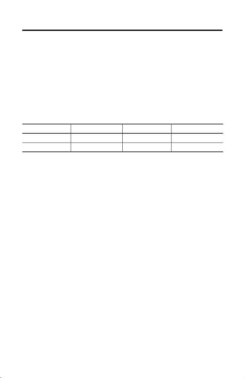
This feature has the following variations.
Module Mode Description
Null Contains an empty or disabled scan list (default)
Master Serves as a master to one or more slaves but is not simultaneously serving as a slave to
another master
Slave Serves as a slave to another master
Dual Serves as both a master to one or more slaves and as a slave to another master
simultaneously
Poll
A poll message is a point-to-point transfer of data (0…255 bytes) sent by the scanner module
that solicits a response from a single device. The device responds with its input data
(0…255 bytes).
Strobe
A strobe message is a multicast transfer of data (64 bits in length) sent by the scanner module
that solicits a response from each strobed slave device. There is one bit for each of the
possible 64 node addresses. The devices respond with their data, which can be as much as
8bytes.
Change of State
Change of state enables the scanner module to perform a scan:
• whenever a network data change occurs.
• at a user-configurable heartbeat rate.
Because data is only sent on an as-needed basis, this feature increases system performance by
reducing network traffic.
Cyclic I/O
Cyclic I/O allows you to instruct the scanner module to perform a scan at a specific send rate.
Because data is only sent at a periodic rate, this feature increases system performance by
reducing network traffic.
Publication 1747-IN058F-EN-P - December 2010
Page 6
6 1747-SDN DeviceNet Scanner Module
Pass-through
The SLC 500 pass-through feature allows communication with the DeviceNet network from
another network. This feature can be used to adjust and fine tune the nodes on your network.
The pass-through feature is not intended to replace a 1770-KFD, 1784-PCD, 1784-PCID, or
1784-PCIDS connection to the network.
To use the pass-through feature you must meet the following hardware, software and
firmware requirements.
Pass-through Requirements
SLC 500 Processor 1747-SDN Firmware RSLinx Software M0 and M1 Files
SLC 5/03 or later 4.015…5.001 2.10 or later Configured for 361 words
SLC 5/03 or later 6.001 or later 2.31 or later Configured for 395 words
U2DN module
The pass-through feature is not intended to replace a 1784-U2DN, 1770-KFD, 1784-PCD,
1784-PCID, or 1784-PCIDS connection to the network.
Publication 1747-IN058F-EN-P - December 2010
Page 7

1747-SDN DeviceNet Scanner Module 7
DeviceNet
STATUS
MODULE
NET
ADDRESS/ERROR
Module Status indicator
indicates module status
Node address and status
displays numeric codes
and indicates scanner
node address or error
Network Status indicator indicates status
of DeviceNet channel communication link
Access door
Wiring color codes
10-pin linear plug inserted
into DeviceNet port
Hardware Features
Use this illustration to identify the external features of the scanner module.
Before You Begin
Before you install your module you need the following items.
• Personal computer with Microsoft Windows 2000 or later operating system
• RSNetWorx for DeviceNet software, version 2.22 or later
• RSLogix 500 software
• SLC 1746 chassis with SLC 5/02, SLC 5/03, SLC 5/04, or SLC 5/05 processor
Publication 1747-IN058F-EN-P - December 2010
Page 8

8 1747-SDN DeviceNet Scanner Module
For network communication, you have three options.
• Use the pass-through feature to communicate with the DeviceNet network from
another network. This method is intended for fine tuning and adjustment of network
devices.
• Use a 1770-KFD RS-232 DeviceNet adapter or 1784-PCD, 1784-PCID, or
1784-PCIDS DeviceNet PC card. This method is necessary for a complete network
configuration and real time monitoring of your network devices.
• Use a 1784-U2DN USB adapter, a 1770-KFD RS-232 DeviceNet adapter or
1784-PCD, 1784-PCID, or 1784-PCIDS DeviceNet PC card. This method is
necessary for a complete network configuration and real time monitoring of your
network devices.
Before you install your module you must know how to:
• program and operate an Allen-Bradley SLC 500 programmable controller.
• install and configure the devices on your DeviceNet network.
Electronic Data Sheet Requirement
This release of the scanner module requires the latest EDS file for RSLinx Classic and
RSNetWorx for DeviceNet software. If the software displays the device as an
Unrecognized Device, the EDS file must be installed.
You can download the latest EDS file online at:
http://www.ab.com/networks/eds
For FRN 8.002 and later, you can upload the embedded EDS file from the scanner module
itself.
1. Open RSLinx Classic or RSNetWorx for DeviceNet software and right click on the
Unrecognized Device.
2. Select Upload EDS file from device for RSLinx Classic software or Register
Device for RSNetWorx for DeviceNet software.
3. Follow the instructions in the EDS wizard to complete the installation.
Perform a ControlFLASH Update
If you want to upgrade the scanner module to a newer firmware release, you must perform a
ControlFLASH update. To get the kit, contact Rockwell Automation Technical Support at
Publication 1747-IN058F-EN-P - December 2010
Page 9

1747-SDN DeviceNet Scanner Module 9
IMPORTANT
IMPORTANT
WARNING
440.646.5800. To install the kit, refer to the ControlFLASH Firmware Upgrade Kit User
Manual, publication 1756-QS105.
You can update Series A and B scanner modules up to FRN 7.006. Series C
scanner modules support only FRN 8.001 to 8.006. Series D scanner modules
support FRN 9.001 and later.
Confirm Processor and Adapter Compatibility
Make sure that your processor and adapter are compatible. You can use the 1747-SDN
scanner module in any slot in an I/O chassis except for the leftmost, which is reserved for the
SLC 500 processor.
You cannot use the scanner module in a remote I/O chassis with a 1747-ASB
adapter module. The adapter module does not support M-file transfer.
Install DeviceNet Scanner Module
Follow these steps to install the module.
1. Turn off the chassis power supply.
If you insert or remove the module while backplane power is on, an electrical
arc can occur. This could cause an explosion in hazardous location installations.
Be sure that power is removed or the area is nonhazardous before proceeding.
2. Select a slot for the module in the chassis.
You may use any slot except the leftmost slot, which is reserved for the SLC 500
processor.
Publication 1747-IN058F-EN-P - December 2010
Page 10

10 1747-SDN DeviceNet Scanner Module
ATTENTION
3. Insert the module into the slot you have selected.
4. Apply firm, even pressure to seat the module in the I/O chassis backplane
connectors.
Connect the Module to the DeviceNet Network
Follow these steps to connect the module to the DeviceNet network.
Publication 1747-IN058F-EN-P - December 2010
To comply with the CE Low Voltage Directive (LVD), DeviceNet must be
powered from a source compliant with the following:
• Safety Extra Low Voltage (SELV)
• Protected Extra Low Voltage (PELV).
To comply with UL restrictions, DeviceNet must be powered from a source
compliant with the following:
• Class 2
• Limited Voltage/Current.
1. Turn off the network power supply.
Page 11

1747-SDN DeviceNet Scanner Module 11
WARNING
+24V Red
Can_H White
Drain/Shield
Can_L Blue
+24V Return Black
Front of Module
10-pin linear
plug
Red
White
Shield
Blue
Black
10-pin Linear plug
DeviceNet drop line
DeviceNet port
connector
If you connect or disconnect the communications cable with power applied to
this module or any device on the network, an electrical arc can occur. This could
cause an explosion in hazardous location installations.
2. Connect the DeviceNet drop line to the 10-pin linear plug by matching the wire
insulation colors to the colors shown on the label.
3. Locate the DeviceNet port connector on the front of the module.
4. Insert the 10-pin linear plug into the DeviceNet port connector.
You have installed and wired your module. To operate the module you must apply power and
then configure and program the SLC processor to communicate with it.
Publication 1747-IN058F-EN-P - December 2010
Page 12

12 1747-SDN DeviceNet Scanner Module
DeviceNet
STATUS
MODULE NET
ADDRESS/ERROR
Module
Numeric
Indicators
Apply Chassis Power
When you apply chassis power, the module numeric indicators cycle through the following
displays.
• Seven-segment lamp test (88)
• Firmware major revision (01…7F hexadecimal)
• Firmware minor revision (01…FF hexadecimal)
• Communication rate (indicates 00 for the default of 125, 01 for 250, or 02 for
500 Kbps)
• Node address (00…63 with 63 as the default)
Use the RSNetWorx for DeviceNet software to change the communication rate and node
address.
Refer to the Numeric Code Display Summary table on page 14 for a complete listing of
numeric displays.
Interpret the LED Indicators
The bicolor (green/red) module status indicator (MODULE) on the front of your module
displays module status. It indicates whether the module has power and is functioning
properly.
Module Status LED Indicator
Indicator Color Description Corrective Action
Off There is no power applied to the
Green The module is operating normally. No action required.
Flashing Green The module is not configured. Configure the module.
Flashing Red There is an invalid configuration. Check configuration setup.
Red The module has an unrecoverable
Publication 1747-IN058F-EN-P - December 2010
module.
fault.
Verify power connections and apply
power.
Replace the module.
Page 13

1747-SDN DeviceNet Scanner Module 13
The DeviceNet channel has a bicolor (green/red) network status indicator (NET). The
following table provides troubleshooting information about the DeviceNet channel
communication link.
DeviceNet Channel Communication
Indicator
Color
Off The channel is disabled for
Green All slave devices in the scan
Flashing
Green
Flashing
Red
Red The module may be
Description Device Operation Corrective Action
DeviceNet communication.
list table are communicating
normally with the module.
The channel is enabled but
no communication is
occurring.
At least one of the slave
devices in the module’s scan
list table has failed to
communicate with the
module.
defective.
The device has no power or
the channel is disabled for
communication due to bus off
condition, loss of network
power, or has been
intentionally disabled.
Normal operation. None.
The two-digit numeric display
for the channel indicates an
error code that provides more
information about the
condition of the channel.
The two-digit numeric display
for the channel displays an
error code that provides more
information about the
condition of the channel.
The communications channel
has failed. The two-digit
numeric display for the
channel displays an error code
that provides more information
about the condition of the
channel.
Power-up the module, provide
network power to the channel,
and be sure the channel is
enabled in both the module
configuration table and the
module command word.
Configure the scan list table
for the channel to add devices.
Examine the failed device and
the scan list table for accuracy.
Reset module. If failures
persist, replace module.
Publication 1747-IN058F-EN-P - December 2010
Page 14

14 1747-SDN DeviceNet Scanner Module
Numeric Codes and Descriptions
Your module uses numeric displays to indicate diagnostic information about the status of
your module. The display flashes at 1-second intervals. The following table summarizes the
meanings of the numeric codes.
Numeric
Code
0…63 Normal operation. The numeric display
70 Module failed Duplicate Node Address check. Change the module channel address to another
71 Illegal data in scan list table (node number
72 Slave device stopped communicating (node
73 Identity information for the device does not
74 Data overrun on port detected. Modify your configuration and check for invalid
75 No traffic from other modules detected on the
76 No direct network traffic for module detected. None. The module detects other network
77 Data size expected by the device does not
78 Slave device in scan list table does not exist. Add the device to the network, or delete the
79 Module has failed to transmit a message. Make sure that your module is connected to a
80 Module is in Idle mode. Put controller in Run mode. Enable Run bit in
81 Module is in Fault mode. Check Module Command Register for fault bit
Description Corrective Action
None.
indicates the 1747-SDN node address on the
DeviceNet network.
available one. The node address you selected
is already in use on that channel.
Reconfigure the scan list table and remove any
alternately flashes).
number alternately flashes).
match electronic key in scan list table entry.
network.
match scan list entry.
illegal data.
Inspect the field devices and verify
connections.
Verify that the correct device is at this node
number. Make sure that the device at the
scrolling node address matches the desired
electronic key (vendor, product code, product
type).
data. Check network communication traffic.
Check the network configuration. Scanlist may
be empty.
communication.
Reconfigure your module for the correct
transmit and receive data sizes.
scan list entry for that device.
valid network.
Check for disconnected cables.
module command register.
set.
Publication 1747-IN058F-EN-P - December 2010
Page 15

1747-SDN DeviceNet Scanner Module 15
Numeric
Code
82 Error detected in sequence of fragmented I/O
83 Slave device is returning error responses when
84 Module is initializing the DeviceNet network. None. This code clears itself once module
85 Data size was incorrect for this device at
86 Device is producing zero length data (idle
87 The primary owner has not allocated the slave. Put the primary owner online.
88 The connection choices (polled, strobed)
89 Slave device initialization using Auto Device
90 User has disabled communication port. Check Module Command Register for DISABLE
91 Bus-off condition detected on comm port.
92 No network power detected on communication
95 Application FLASH update in progress. None. Do not disconnect the module while
97 Module operation halted by user command. Check Module Command Register for HALT bit
Description Corrective Action
Check scan list table entry for slave device to
messages from device.
module attempts to communicate with it.
runtime.
state) while module is in Run mode.
between the primary connection and the
shared input only connection do not match.
Replacement parameters failed.
Module is detecting communication errors.
port.
make sure that input and output data lengths
are correct. Check slave device configuration.
Check accuracy of scan list table entry. Check
slave device configuration. Slave device may
be in another master’s scan list. Reboot slave
device.
attempts to initialize all slave devices on the
network.
Slave device is transmitting incorrect length
data.
Verify device is not configured for variable poll
connection size.
Try replacing the device.
Check device configuration and slave node
status.
Reconfigure the shared input-only connection
choices to be the same as, or a subset of, the
choices for the primary connection.
Put the slave device into configurable mode.
If the slave is configured offline, check its EDS
file.
Check to see if the slave device has been
replaced with an incompatible device.
bit set.
Check DeviceNet connections and physical
media integrity. Check system for failed slave
devices or other possible sources of network
interference.
Provide network power. Make sure that
module drop cable is providing network power
to module comm port.
application FLASH is in progress. You will lose
existing data in the module memory.
set.
Publication 1747-IN058F-EN-P - December 2010
Page 16

16 1747-SDN DeviceNet Scanner Module
Numeric
Code
98 Unrecoverable firmware failure. Service or replace your module.
99 Unrecoverable hardware failure. Service or replace your module.
E2 RAM Test Failure Service or replace your module.
E4 Lost power during FLASH upgrade Service or replace your module.
E5 No application code Service or replace your module.
E9 Module memory has been flushed for factory
Description Corrective Action
Cycle module power to recover.
default settings.
Specifications
SLC DeviceNet Scanner — 1747-SDN
Attribute Value
Module location SLC 5/02 or later chassis
Module defaults Node Address – 63
Power consumption
- Backplane current
- DeviceNet
Isolation voltage 30V (continuous), Basic Insulation Type
Temperature, operating IEC 60068-2-1 (Test Ad, Operating Cold),
Temperature, non-operating IEC 60068-2-1 (Test Ab, Unpackaged Nonoperating Cold),
Relative humidity IEC 60068-2-30 (Test Db, Unpackaged Damp Heat):
Vibration IEC60068-2-6 (Test Fc, Operating):
Shock IEC60068-2-27:1987, Test Ea (Unpackaged shock, ES#002)
Baud Rate – 125 Kbps
5V DC, 500 mA
24V DC, 90 mA Class 2
Tested at 500V AC for 60 s, DeviceNet to backplane
IEC 60068-2-2 (Test Bd, Operating Dry Heat),
IEC 60068-2-14 (Test Nb, Operating Thermal Shock):
o
0…60
C (32…140 oF)
IEC 60068-2-2 (Test Bc, Unpackaged Nonoperating Dry Heat),
IEC 60068-2-14 (Test Na, Unpackaged Nonoperating Thermal Shock):
o
-40…85
C (-40…185 oF)
5…95% non-condensing
2 g @10…500 Hz
Operating — 30 g
Non-operating — 50 g
Publication 1747-IN058F-EN-P - December 2010
Page 17

1747-SDN DeviceNet Scanner Module 17
SLC DeviceNet Scanner — 1747-SDN
Attribute Value
Emissions CISPR 11:
Group 1, Class A (with appropriate enclosure)
ESD immunity IEC 61000-4-2:
Radiated RF immunity IEC 61000-4-3:
EFT/B immunity IEC 61000-4-4:
Surge transient immunity IEC 61000-4-5:
Conducted RF immunity IEC 61000-4-6:
Magnetic field immunity IEC 61000-4-8
Enclosure type rating None (open style)
Wiring
- Size
- Category
(1)
10-pin Linear plug
- Torque
- Catalog number
North American temperature code T5
(1)
Use this Conductor Category information for planning conductor routing. Refer to Industrial Automation Wiring and
Grounding Guidelines, publication 1770-4.1
6 kV contact discharges
8 kV air discharges
10 V/m with 1 kHz sine-wave 80% AM from 80…2000 Mhz
+2 kV at 5 kHz on communication ports
±2 kV line-earth(CM) on communications ports
10 Vrms with 1 kHz sine-wave 80% AM from 150 kHz…80 MHz
30A/m long duration at 50 Hz
Refer to DeviceNet Media Design Installation Guide, publication
DNET-UM072
2 — on communication ports
0.6…0.8 Nm (5…7 lb-in)
1787-PLUG10R
.
Publication 1747-IN058F-EN-P - December 2010
Page 18

18 1747-SDN DeviceNet Scanner Module
Certifications - 1747-SDN
Certification (when product is
(1)
marked)
c-UL-us UL Listed Industrial Control Equipment, certified for US and Canada. See
CE European Union 89/336/EEC EMC Directive, compliant with:
C-Tick Australian Radiocommunications Act, compliant with:
ODVA ODVA conformance tested to ODVA DeviceNet specifications
(1)
See the Product Certification link at http://www.ab.com for Declaration of Conformity, Certificates, and other certification
details.
Value
UL File E113724.
UL Listed for Class I, Division 2 Group A, B, C, D Hazardous Locations,
certified for US and Canada. See UL File E10314.
EN 61000-6-2; Industrial Immunity
EN 61000-6-4; Industrial Emissions
AS/NZS CISPR 11; Industrial Emissions
Additional Resources
Resource Description
SLC 500 DeviceNet Scanner Module User Manual, publication
1747-UM655
ControlFlash Firmware Upgrade Kit User Manual, publication
1756-QS105
Getting Results with RSLogix 500, publication LG500-GR002
Getting Results with RSLinx, publication LINX-GR001
DeviceNet Media Design and Installation Guide, DNET-UM072
Getting Results with RSNetWorx for DeviceNet, publication
DNET-GR001
Provides application examples for the
DeviceNet scanner module.
Provides instructions on using ControlFlash
to upgrade the firmware.
Provides information on RSLogix 500
software.
Provides information on RSLinx software.
Provides information on using DeviceNet
communication network.
Provides information on using RSNetWorx
for DeviceNet software.
You can view or download publications at http://literature.rockwellautomation.com. To
order paper copies of technical documentation, contact your local Rockwell Automation
distributor or sales representative.
Publication 1747-IN058F-EN-P - December 2010
Page 19

1747-SDN DeviceNet Scanner Module 19
WARNING
AVERTISSEMENT
North American Hazardous Location Approval
The following information applies when
operating this equipment in hazardous
locations:
Products marked "CL I, DIV 2, GP A, B, C, D" are
suitable for use in Class I Division 2 Groups A, B, C,
D, Hazardous Locations and nonhazardous locations
only. Each product is supplied with markings on the
rating nameplate indicating the hazardous location
temperature code. When combining products within
a system, the most adverse temperature code
(lowest "T" number) may be used to help determine
the overall temperature code of the system.
Combinations of equipment in your system are
subject to investigation by the local Authority Having
Jurisdiction at the time of installation.
EXPLOSION HAZARD
• Do not disconnect equipment
unless power has been
removed or the area is known
to be nonhazardous.
• Do not disconnect connections
to this equipment unless power
has been removed or the area
is known to be nonhazardous.
Secure any external
connections that mate to this
equipment by using screws,
sliding latches, threaded
connectors, or other means
provided with this product.
• Substitution of any component
may impair suitability for Class
I, Division 2.
• If this product contains
batteries, they must only be
changed in an area known to
be nonhazardous.
Informations sur l’utilisation de cet
équipement en environnements
dangereux:
Les produits marqués "CL I, DIV 2, GP A, B, C, D" ne
conviennent qu'à une utilisation en environnements
de Classe I Division 2 Groupes A, B, C, D dangereux et
non dangereux. Chaque produit est livré avec des
marquages sur sa plaque d'identification qui indiquent
le code de température pour les environnements
dangereux. Lorsque plusieurs produits sont combinés
dans un système, le code de température le plus
défavorable (code de température le plus faible) peut
être utilisé pour déterminer le code de température
global du système. Les combinaisons d'équipements
dans le système sont sujettes à inspection par les
autorités locales qualifiées au moment de
l'installation.
RISQUE D’EXPLOSION
• Couper le courant ou s'assurer
que l'environnement est classé
non dangereux avant de
débrancher l'équipement.
• Couper le courant ou s'assurer
que l'environnement est classé
non dangereux avant de
débrancher les connecteurs.
Fixer tous les connecteurs
externes reliés à cet
équipement à l'aide de vis,
loquets coulissants,
connecteurs filetés ou autres
moyens fournis avec ce produit.
• La substitution de tout
composant peut rendre cet
équipement inadapté à une
utilisation en environnement de
Classe I, Division 2.
• S'assurer que l'environnement
est classé non dangereux avant
de changer les piles.
Publication 1747-IN058F-EN-P - December 2010
Page 20

Rockwell Automation Support
Rockwell Automation provides technical information on the Web to assist you in using its
products. At http://support.rockwellautomation.com
.
knowledge base of FAQs, technical and application notes, sample code and links to software
service packs, and a MySupport feature that you can customize to make the best use of these
tools.
For an additional level of technical phone support for installation, configuration and
troubleshooting, we offer TechConnect support programs. For more information, contact
your local distributor or Rockwell Automation representative, or visit
ttp://support.rockwellautomation.com.
h
Installation Assistance
If you experience a problem within the first 24 hours of installation, please review the
information that's contained in this manual. You can also contact a special Customer Support
number for initial help in getting your product up and running.
United States 1.440.646.3434
Monday – Friday, 8 a.m. – 5 p.m. EST
Outside United States Please contact your local Rockwell Automation representative for any technical
support issues.
New Product Satisfaction Return
Rockwell Automation tests all of its products to ensure that they are fully operational when
shipped from the manufacturing facility. However, if your product is not functioning and
needs to be returned, follow these procedures.
, you can find technical manuals, a
United States Contact your distributor. You must provide a Customer Support case number (call the
Outside United States Please contact your local Rockwell Automation representative for the return
Rockwell Auotmation, Allen-Bradley, TechConnect, SLC, SLC 500, SLC 5/02, SLC 5/03, SLC 5/04, SLC 5/05, RSLinx, RSLogix 500, and
RSNetWorx are trademarks of Rockwell Automation, Inc.
Trademarks not belonging to Rockwell Automation are property of their respective companies.
phone number above to obtain one) to your distributor in order to complete the return
process.
procedure.
Publication 1747-IN058F-EN-P - December 2010 PN-93987
Supersedes Publication 1747-IN058E-EN-P - February 2007 Copyright © 2010 Rockwell Automation, Inc. All rights reserved. Printed in the U.S.A.
 Loading...