

Page 1

1747-SDN
DeviceNet Scanner
Module
Catalog Number
1747-SDN, Series C
User Manual
Page 2
Important User Information
Solid state equipment has operational characteristics differing from those of
electromechanical equipment. Safety Guidelines for the Application,
Installation and Maintenance of Solid State Controls (publication SGI-1.1
available from your local Rockwell Automation sales office or online at
http://literature.rockwellautomation.com
) describes some important
differences between solid state equipment and hard-wired electromechanical
devices. Because of this difference, and also because of the wide variety of
uses for solid state equipment, all persons responsible for applying this
equipment must satisfy themselves that each intended application of this
equipment is acceptable.
In no event will Rockwell Automation, Inc. be responsible or liable for
indirect or consequential damages resulting from the use or application of
this equipment.
The examples and diagrams in this manual are included solely for illustrative
purposes. Because of the many variables and requirements associated with
any particular installation, Rockwell Automation, Inc. cannot assume
responsibility or liability for actual use based on the examples and diagrams.
No patent liability is assumed by Rockwell Automation, Inc. with respect to
use of information, circuits, equipment, or software described in this manual.
Reproduction of the contents of this manual, in whole or in part, without
written permission of Rockwell Automation, Inc., is prohibited.
Throughout this manual, when necessary, we use notes to make you aware
of safety considerations.
WARNING
Identifies information about practices or circumstances that can cause
an explosion in a hazardous environment, which may lead to personal
injury or death, property damage, or economic loss.
IMPORTANT
ATTENTION
Identifies information that is critical for successful application and
understanding of the product.
Identifies information about practices or circumstances that can lead
to personal injury or death, property damage, or economic loss.
Attentions help you identify a hazard, avoid a hazard, and recognize
the consequence
SHOCK HAZARD
Labels may be on or inside the equipment, for example, a drive or
motor, to alert people that dangerous voltage may be present.
BURN HAZARD
Labels may be on or inside the equipment, for example, a drive or
motor, to alert people that surfaces may reach dangerous
temperatures.
Rockwell Automation, TechConnect, SLC, SLC 500, RSNetWorx for DeviceNet, RediSTATION, Series 9000, DH+, Data Highway
Plus, RSLogix 500, FLEX I/O, ControlFlash, RSView, PLC-5, PanelView, RSLinx Classic, are trademarks of Rockwell Automation,
Inc.
Trademarks not belonging to Rockwell Automation are property of their respective companies.
Page 3

Summary of Changes
The information below summarizes the changes to this manual since
the last publication.
To help you find new and updated information in this release of the
manual, we have included change bars as shown to the right of this
paragraph.
This manual contains this updated information.
Topic Page
The length of the M0 and M1 files 64
Numeric code 65 for normal operation when
AutoScan is enabled was added
91
DeviceNet explicit messaging chapter was
added
AutoScan function chapter was added Chapter 9
Information about programming the module
by using the SLC M0 and M1 files was
added
Information on the 1747-SDN module’s
firmware history was added
Information about data organization was
added
Information about explicit message program
control was added
Chapter 8
123…127
Appendix C
Appendix D
Appendix E
3 Publication 1747-UM655B-EN-P - June 2007
Page 4

4 Summary of Changes
Publication 1747-UM655B-EN-P - June 2007
Page 5

Before You Begin
Planning Your Configuration and
Data Mapping Your Devices
Table of Contents
Preface
Introduction . . . . . . . . . . . . . . . . . . . . . . . . . . . . . . . . . . . . . 9
Audience . . . . . . . . . . . . . . . . . . . . . . . . . . . . . . . . . . . . . . . 9
The Example Application . . . . . . . . . . . . . . . . . . . . . . . . . . 10
Common Techniques Used in This Manual. . . . . . . . . . . . . . 11
Additional Resources. . . . . . . . . . . . . . . . . . . . . . . . . . . . . . 11
Chapter 1
What This Chapter Contains . . . . . . . . . . . . . . . . . . . . . . . . 13
What You Need to Know . . . . . . . . . . . . . . . . . . . . . . . . . . 13
What Your 1747-SDN Module Does . . . . . . . . . . . . . . . . . . . 14
Communicating with Your Devices . . . . . . . . . . . . . . . . . . . 16
Communicating with Your SLC 500 Processor. . . . . . . . . . . . 18
1747-SDN Module Data Tables . . . . . . . . . . . . . . . . . . . . . . 19
RSNetWorx Software as a Configuration Tool . . . . . . . . . . . . 20
What’s Next? . . . . . . . . . . . . . . . . . . . . . . . . . . . . . . . . . . . . 22
Chapter 2
What This Chapter Contains . . . . . . . . . . . . . . . . . . . . . . . . 23
What You Need to Know . . . . . . . . . . . . . . . . . . . . . . . . . . 23
Beginning the Process. . . . . . . . . . . . . . . . . . . . . . . . . . . . . 24
The Example Network. . . . . . . . . . . . . . . . . . . . . . . . . . . . . 24
What’s Next? . . . . . . . . . . . . . . . . . . . . . . . . . . . . . . . . . . . . 30
Hardware Setup
Configuring the DeviceNet
Network
Chapter 3
What This Chapter Contains . . . . . . . . . . . . . . . . . . . . . . . . 31
Installing the 1770-KFD Module. . . . . . . . . . . . . . . . . . . . . . 31
Installing the SLC 500 Processor. . . . . . . . . . . . . . . . . . . . . . 32
Installing the ControlNet RS-232 Interface Module . . . . . . . . 35
Installing the 1747-SDN Module. . . . . . . . . . . . . . . . . . . . . . 40
Installing the RediSTATION Operator Interface. . . . . . . . . . . 43
Installing the Series 9000 Photoeye . . . . . . . . . . . . . . . . . . . 44
How Your Network Will Look . . . . . . . . . . . . . . . . . . . . . . . 45
What’s Next? . . . . . . . . . . . . . . . . . . . . . . . . . . . . . . . . . . . . 46
Chapter 4
What This Chapter Contains . . . . . . . . . . . . . . . . . . . . . . . . 47
Installing the Software. . . . . . . . . . . . . . . . . . . . . . . . . . . . . 47
Use RSLinx Software to Configure the DeviceNet Driver . . . . 48
Using RSNetWorx for DeviceNet Software to Configure the
1747-SDN Module Scanlist . . . . . . . . . . . . . . . . . . . . . . . . . . 50
What’s Next? . . . . . . . . . . . . . . . . . . . . . . . . . . . . . . . . . . . . 62
5 Publication 1747-UM655B-EN-P - June 2007
Page 6

6 Table of Contents
Communicating with the
DeviceNet Network from Another
Network
Creating and Running the Example
Application Program
Troubleshooting
Chapter 5
What This Chapter Contains . . . . . . . . . . . . . . . . . . . . . . . . 63
Additional Resources. . . . . . . . . . . . . . . . . . . . . . . . . . . . . . 64
System Requirements . . . . . . . . . . . . . . . . . . . . . . . . . . . . . 64
Communicating with the DeviceNet Network via
an Ethernet Network . . . . . . . . . . . . . . . . . . . . . . . . . . . . . . 65
Communicate with the DeviceNet Network via
a DH+ Network . . . . . . . . . . . . . . . . . . . . . . . . . . . . . . . . . 73
What’s Next? . . . . . . . . . . . . . . . . . . . . . . . . . . . . . . . . . . . . 78
Chapter 6
What This Chapter Contains . . . . . . . . . . . . . . . . . . . . . . . . 79
Install the Software . . . . . . . . . . . . . . . . . . . . . . . . . . . . . . . 80
Create the Example Application Program . . . . . . . . . . . . . . . 80
Download and Run the Program . . . . . . . . . . . . . . . . . . . . . 82
What’s Next? . . . . . . . . . . . . . . . . . . . . . . . . . . . . . . . . . . . . 87
Chapter 7
Module Status Indicator. . . . . . . . . . . . . . . . . . . . . . . . . . . . 89
Network Status Indicator . . . . . . . . . . . . . . . . . . . . . . . . . . . 90
Numeric Display Code Summary . . . . . . . . . . . . . . . . . . . . . 90
DeviceNet Explicit Messaging
AutoScan
Data Map Example
Configuring the M0/M1 Files by
Using RSLogix 500 Software
Chapter 8
DeviceNet Explicit Message Instruction Overview. . . . . . . . . 93
DeviceNet Explicit Message (DEM) . . . . . . . . . . . . . . . . . . . 94
Chapter 9
Overview . . . . . . . . . . . . . . . . . . . . . . . . . . . . . . . . . . . . . 103
Implementing AutoScan . . . . . . . . . . . . . . . . . . . . . . . . . . 103
Other Important Information about AutoScan. . . . . . . . . . . 112
Appendix A
What This Appendix Contains . . . . . . . . . . . . . . . . . . . . . . 115
Example Input Mapping Scheme . . . . . . . . . . . . . . . . . . . . 115
Example Output Mapping Scheme. . . . . . . . . . . . . . . . . . . 118
Appendix B
RSLogix 500 I/O Configuration . . . . . . . . . . . . . . . . . . . . . 121
Programming the Module by Using the SLC M0
and M1 Files . . . . . . . . . . . . . . . . . . . . . . . . . . . . . . . . . . . 123
Publication 1747-UM655B-EN-P - June 2007
Page 7

1747-SDN Module Firmware
History
Data Organization
Explicit Message Program Control
Table of Contents 7
Appendix C
Purpose . . . . . . . . . . . . . . . . . . . . . . . . . . . . . . . . . . . . . . 129
Revision 8.002. . . . . . . . . . . . . . . . . . . . . . . . . . . . . . . . . . 129
Revisions 7.005 and 7.006 Known Anomalies . . . . . . . . . . . 129
Revision 6.002. . . . . . . . . . . . . . . . . . . . . . . . . . . . . . . . . . 130
Revision 5.001. . . . . . . . . . . . . . . . . . . . . . . . . . . . . . . . . . 132
Revision 4.026. . . . . . . . . . . . . . . . . . . . . . . . . . . . . . . . . . 132
Appendix D
Understand the Data Organization of the Module . . . . . . . . 133
Upload Input Data from the Module to the SLC Processor. . 134
Download Output Data to the Module. . . . . . . . . . . . . . . . 138
Appendix E
Using Explicit Message Program Control . . . . . . . . . . . . . . 143
Glossary
Index
Publication 1747-UM655B-EN-P - June 2007
Page 8

8 Table of Contents
Publication 1747-UM655B-EN-P - June 2007
Page 9

Preface
Introduction
This user manual is designed to provide you enough information to
get a small example application up and running. Use this manual if
you are knowledgeable about DeviceNet and SLC 500 products, but
may not have used the products in conjunction. The information
provided is a base; modify or expand the examples to suit your
particular needs.
The manual contains instructions on configuring a DeviceNet network
by using RSLinx and RSNetWorx for DeviceNet software. It also
describes how to use the SLC 500 pass-through feature to
communicate with the DeviceNet network for adjustment and tuning
of network devices via an Ethernet and Data Highway Plus (DH+)
network.
The example application demonstrates how to perform control on a
DeviceNet network by using an SLC 500 processor and the 1747-SDN
module. You use RSLogix 500 programming software to create a
ladder logic program to control a photoeye and a RediSTATION
operator interface.
Audience
IMPORTANT
This manual is intended for control engineers and technicians who are
installing, programming, and maintaining a control system that
includes an SLC 500 processor communicating on a DeviceNet
network through a 1747-SDN module.
We assume that you:
• are developing a DeviceNet network by using a SLC 500
processor in conjunction with a 1747–SDN module.
• know each of your device’s I/O parameters and requirements.
• understand SLC processor programming and operation.
• are experienced with the Microsoft Windows environment.
• are familiar with RSNetWorx for DeviceNet software.
This user manual should be used in conjunction with the
1747-SDN DeviceNet Scanner Module Installation Instructions,
publication 1747-IN058. The installation instructions contain
important information on configuring your scanner.
9 Publication 1747-UM655B-EN-P - June 2007
Page 10

10 Preface
The Example Application
This manual describes how to set up an example application. The
manual provides examples of each step of the setup, with references
to other manuals for more details.
System Components
We used the following devices and software for the example
application. For your own application, substitute your own devices to
fit your needs. The recommended configurations in this user manual
will help you set up the test system and get it working. Your eventual
configuration will depend on your application.
TIP
If you use different software or fimware versions of these
products, some of your dialogs may appear slightly different
from those shown in the example.
Quantity Product Name Catalog Number Series/Revision
Hardware
1 SLC 500 modular chassis 1746-A4, 1746-A7, 1746-A10,
1746-A13
1 SLC 500 power supply 1746-P1, 1746-P2, 1746-P3,
1746-P4, 1746-P5, 1746-P6
1 SLC 5/04 processor 1747-L541, 1747-L542,
1747-L543
1 SLC 5/05 processor (Ethernet
network)
1 DeviceNet scanner module 1747-SDN/B 1 ControlNet RS-232 interface
module
1 DeviceNet quad-tap 1492-DN3TW 1 RediSTATION operator interface
module
1 Series 9000 photoeye 42GNU-9000 or equivalent 1 DeviceNet RS-232 interface
module
1 RS-232 cables 1787-RSCABL/A (personal
DeviceNet dropline or trunk
cables, as needed
1747-L551, 1747-L552,
1747-L553
1747-KFC15 B
2705-TxDN1x42x-xxxx -
1770-KFD -
computer to 1770-KFD)
1787-PCABL, 1787-TCABL,
1787-MCABL
B
-
-
-
-
-
Publication 1747-UM655B-EN-P - June 2007
Page 11
Quantity Product Name Catalog Number Series/Revision
1 24V power supply Any regulated 24V dc, 8 A -
Preface 11
1 Personal computer IBM-compatible Pentium+
Windows 2000 or later
Software
RSLogix 500 9324-RL0300xxx Rev 4.00
RSNetWorx for DeviceNet 9357-DNETL3 Rev 2.22
RSLinx 9355-WAB Rev 2.10
Common Techniques Used in This Manual
The following conventions are used throughout this manual:
• Bulleted lists provide information, not procedural steps.
• Numbered lists provide sequential steps.
This symbol identifies helpful tips.
Additional Resources
TIP
These documents contain additional information concerning related
Rockwell Automation products.
-
Resource Description
1747-SDN DeviceNet Scanner Module
Installation Instructions, publication 1747-IN058
ControlFlash Firmware Upgrade Kit Quick Start,
publication 1756-QS105
Getting Results with RSLogix 500, publication
LG500-GR002
Getting Results with RSLinx Classic, publication
LINX-GR001
DeviceNet Media Design and Installation Guide,
publication DNET-UM072
Getting Results with RSNetWorx for DeviceNet,
publication DNET-GR001
DeviceNet RS-232 Interface Module, publication
1770-5.6
SLC 500 ControlNet RS-232 Interface User
Manual, publication 1747-5.34
Provides information on installing
and connecting the module.
Provides instructions on using the
ControlFlash utility to upgrade the
firmware.
Provides information on RSLogix
500 software.
Provides information on RSLinx
software.
Provides information on using
DeviceNet communication network.
Provides information on using
RSNetWorx for DeviceNet
software.
Provides information on connecting
and installing the DeviceNet
RS-232 Interface module.
Provides information about the
1747-KFC15 module.
Publication 1747-UM655B-EN-P - June 2007
Page 12

12 Preface
Resource Description
ControlNet Coax Media Planning and Installation
Guide, publication CNET-IN002
RediSTATION operator interface User Manual,
publication 2705-UM001
SLC 500 Module Hardware Style User Manual,
publication 1747-UM011
Quick Start for experienced Users, publication
1747-10.4
Provides information on planning
and installing ControlNet coax
media systems.
Provides information on installing
and using the RediSTATION
operator interface.
Provides information on installing,
wiring, startup, and maintenance of
SLC modular hardware.
Provides information on features,
setup, configuration, and
communication for the SLC 500
Ethernet processors.
You can view or download publications at
http://literature.rockwellautomation.com
. To order paper copies of
technical documentation, contact your local Rockwell Automation
distributor or sales representative.
Publication 1747-UM655B-EN-P - June 2007
Page 13

Before You Begin
Chapter
1
What This Chapter Contains
This chapter provides an overview of communication between the
SLC 500 processor and DeviceNet devices via the 1747-SDN module.
The configuration data tables and the RSNetWorx for DeviceNet
software dialogs and dialogs used to configure the data tables are also
described.
The following table identifies what this chapter contains and where to
find specific information.
Topic Page
What You Need to Know 13
What Your 1747-SDN Module Does 14
Communicating with Your Devices 16
Communicating with Your SLC 500
Processor
1747-SDN Module Data Tables 19
RSNetWorx Software as a Configuration
Tool
18
20
What’s Next? 22
What You Need to Know
13 Publication 1747-UM655B-EN-P - June 2007
Before configuring your 1747-SDN module, you must understand:
• the data exchange between the an SLC 500 processor and
DeviceNet devices through the 1747-SDN module.
• user-configurable 1747-SDN module data tables.
• the role of RSNetWorx for DeviceNet software.
Page 14
14 Before You Begin
What Your 1747-SDN Module Does
SLC 500 Modular Chassis
SLC 500
Processor
1747-SDN Interface
Module
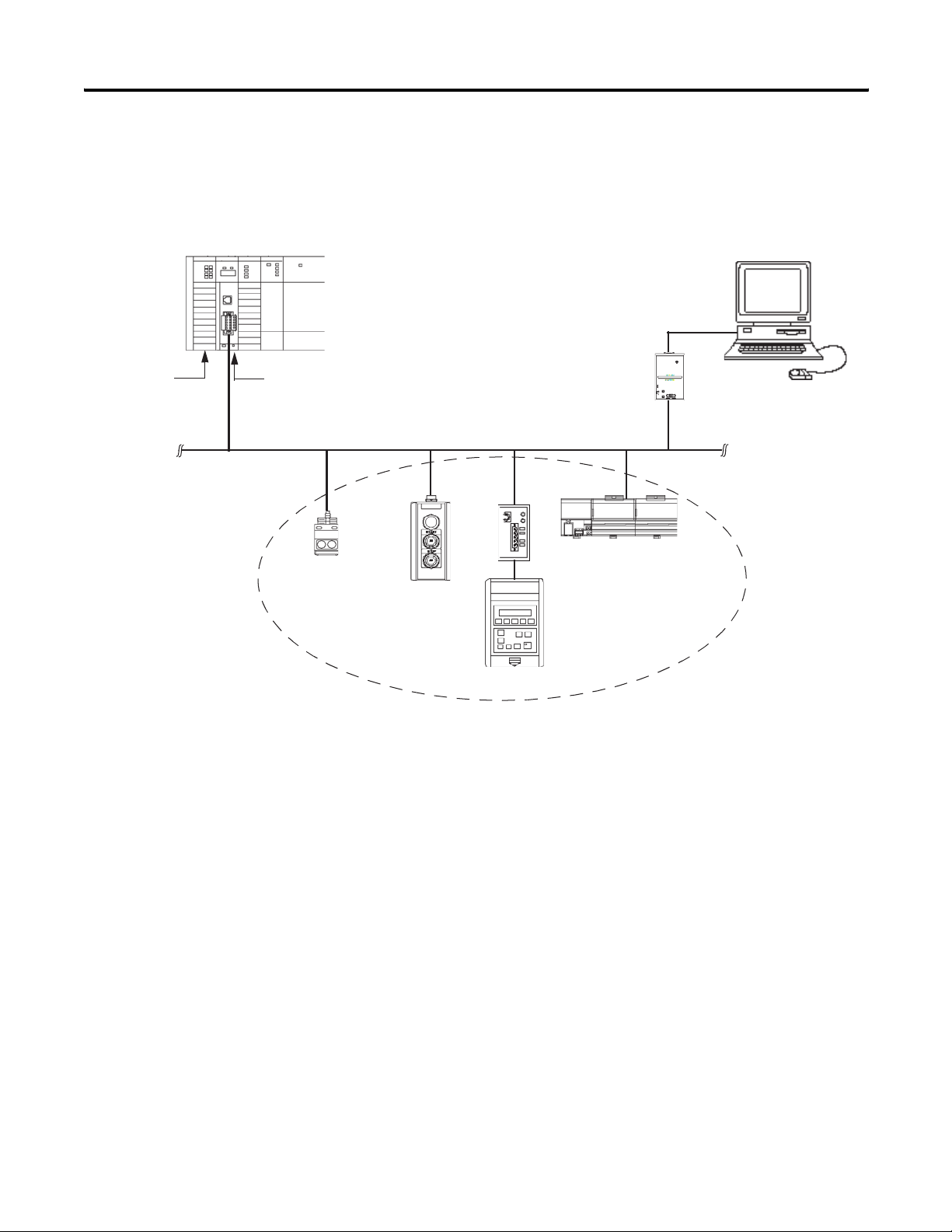
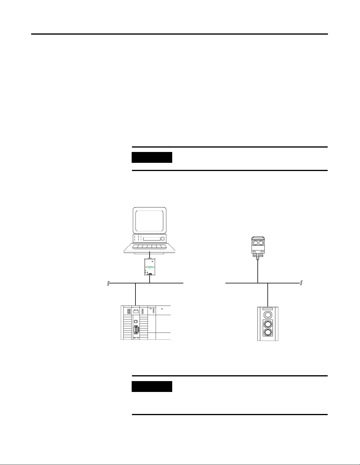
In a typical configuration, the 1747-SDN module acts as an interface
between DeviceNet devices and the SLC 500 processor.
Typical DeviceNet Network
Series 9000
Photoeye
RediSTATION
Operator
Interface
Computer with RSNetWorx
for DeviceNet Software
1770-KFD PC
Communication Module
FLEX I/O
Rack
DeviceNet
Devices
1305 Drive
The 1747-SDN module communicates with DeviceNet devices over
the network to:
• read inputs from a device.
• write outputs to a device.
• download configuration data.
• monitor a device’s operational status.
The 1747-SDN module communicates with the processor in the form
of M1/M0 File Transfers and/or Discrete I/O. Information exchanged
includes the following:
• Device I/O data
• Status information
• Configuration data
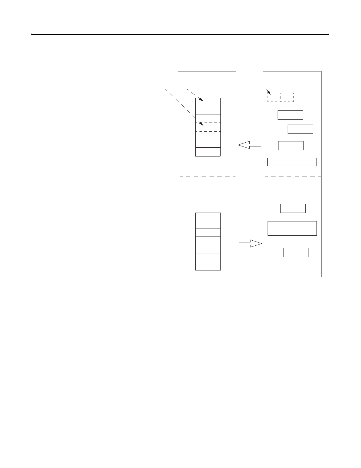
A processor to I/O DeviceNet configuration is shown in the following
figure. See the referenced chapters for more information.
Publication 1747-UM655B-EN-P - June 2007
Page 15
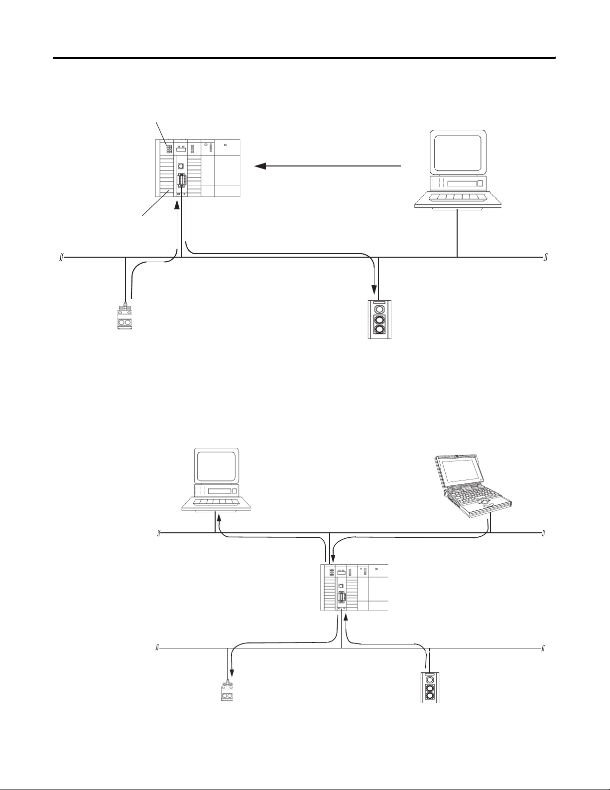
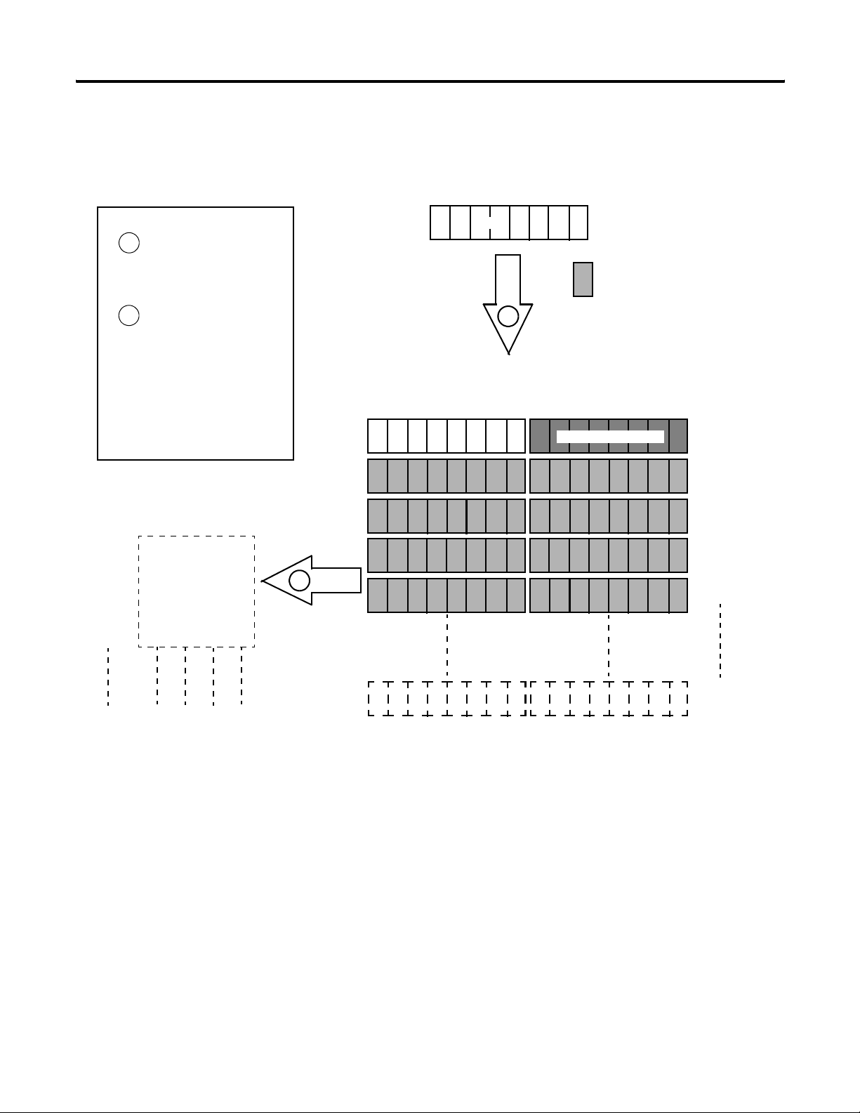
Processor to I/O
Before You Begin 15
Input Read by Processor (Chapter 2)
Output Write by
Processor (Chapter 2)
Input Data from
Device to SDN
(Chapter 2)
Input
Device
Configure SDN Module (Chapter 4)
Computer
Configure SDN Module (Chapter 4)
Mapping Table (Chapters 2 and 4)
Output Data to Devices
from SDN (Chapter 2)
DeviceNet Network
Output
Device
Running
RSNetWorx for
DeviceNet
Software
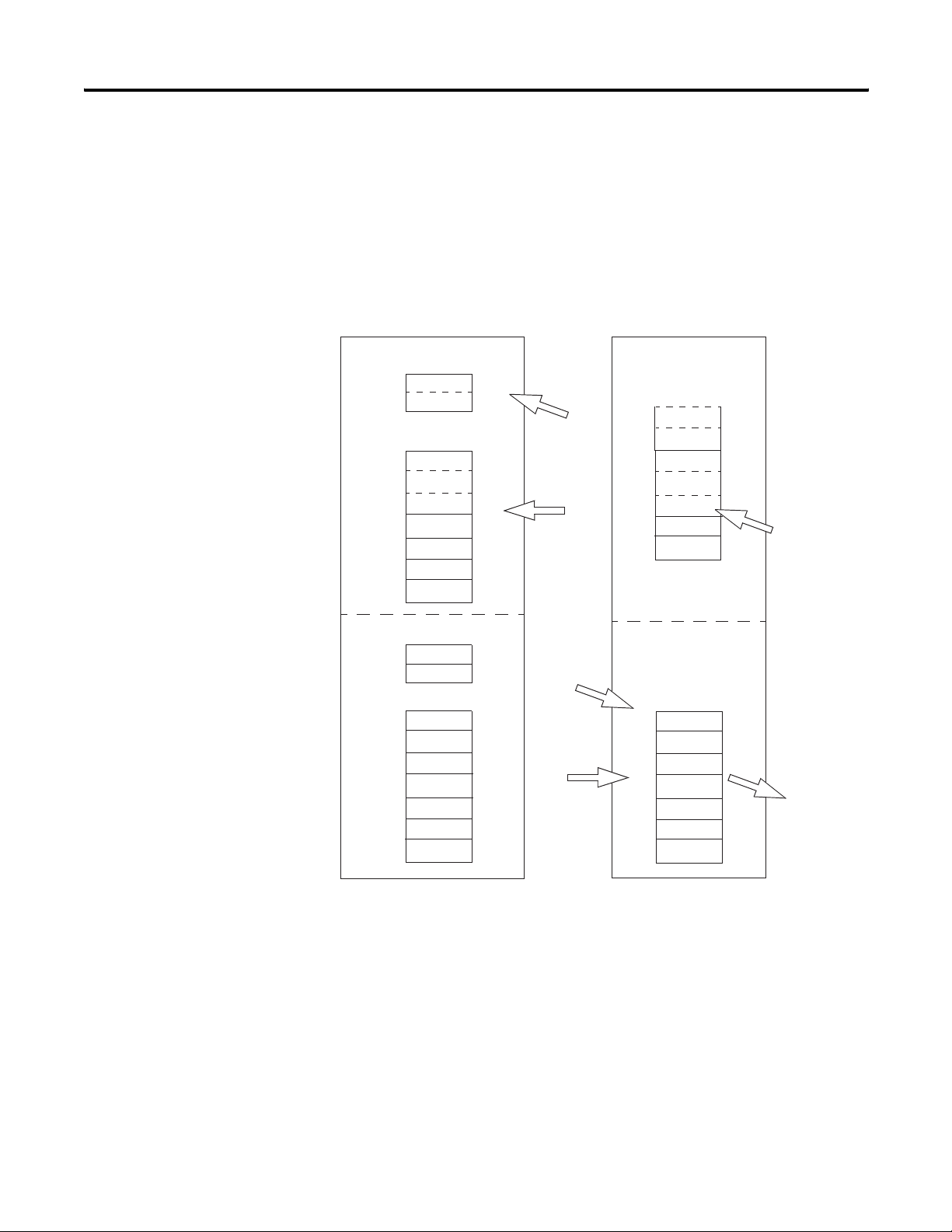
The 1747-SDN interface module can also be used to bridge a
DeviceNet network with another network.
Target device to
be configured.
Configuring Devices and Data Collection on Higher-level Networks via
SLC 500/SDN Module
Industrial
workstation running
RSView software.
DH+ or Ethernet Network (Chapter 5)
Configuration of device
using RSNetWorx
software (Chapter 4).
DeviceNet Network
Laptop computer
running RSNetWorx
software.
Collection of status
or alarm data
(Chapter 6).
1747-SDN
Module
Source device
to collect data.
Publication 1747-UM655B-EN-P - June 2007
Page 16

16 Before You Begin
Communicating with Your Devices
The 1747-SDN module communicates with a device via strobe, poll,
change of state, and/or cyclic messages. It uses these messages to
solicit data from or deliver data to each device. Data received from the
devices, or input data, is organized by the 1747-SDN module and
made available to the processor. Data received from your SLC 500
processor, or output data, is organized in the 1747-SDN module and
sent on to your devices.
IMPORTANT
Throughout this document, input and output are defined from
the SLC 500 processor’s point of view. Output is data sent from
the SLC 500 processor to a device. Input is data collected by the
SLC 500 processor from a device.
All data sent and received on a DeviceNet network is in byte
lengths. A device may, for example, produce only two bits of
input information. Nevertheless, since the minimum data size
on a DeviceNet network is one byte, two bits of information are
included in the byte of data produced by the device. In this
example (only two bits of input information), the upper six bits
are insignificant.
Publication 1747-UM655B-EN-P - June 2007
Page 17
Communicating With Other Devices
Before You Begin 17
Different portions of data from a single
device can be mapped to separate
1747-SDN memory locations. For example,
On/Off values can be mapped to one
location, diagnostic values to another. This
is known as map segmenting. This concept
is illustrated by byte A, stored separately
as segments A1 and A2.
1747-SDN Module
Input Data Storage
A1
B
C
A2
D
E
E
Output Data Storage
X
Y
Y
Y
Y
Z
Byte
0
1
2
3
4
5
6
Input from
the devices
to the
SLC 500
processor.
Output from
the SLC 500
processor.
DeviceNet Devices
Input Data From
DeviceNet Devices
A2
A1
B
C
D
E
Output Data To
DeviceNet Devices
X
Y
Z
Publication 1747-UM655B-EN-P - June 2007
Page 18
18 Before You Begin
Communicating with Your SLC 500 Processor
The 1747-SDN module does not send data to your processor. Data
transferred between the module and the processor must be initiated
by the processor. Output data is sent, or written, to the scanner by
your processor by placing the data in the M0 file. This data is
organized in the scanner, which in turn passes the data on to the
scanned devices via strobe, poll, change of state, or cyclic messages.
Data Flow
SLC 500 Processor
Discrete Input Image
B
A1
M1/M0 File Transfer Data File
C
A2
D
E
E
Discrete I/O
Tra ns fe r
I/O Map
M1 File
Tra ns fe r
(Read)
1747-SDN Module
Internal Input
Data Storage
A1
B
C
A2
D
E
E
Input from
the devices.
Discrete Output Image
X
M0 Data File
Z
Y
Y
Y
Y
Discrete I/O
Transfer
I/O Map
M0 File
Transfer
(Write)
Internal
Output Data
Storage
X
Y
Y
Y
Y
Z
Output to
the devices.
Publication 1747-UM655B-EN-P - June 2007
Page 19

Before You Begin 19
1747-SDN Module Data Tables
To manage the flow of data between your SLC 500 processor and the
network devices, the 1747-SDN module uses the following data tables:
• Scanner configuration table (SCT)
• Scanlist table (SLT)
• Device input data table
• Device output data table
• Device active table
• Device failure table
• Client/Server transaction tables
You can configure the first two of these data tables through
RSNetWorx for DeviceNet software.
• Scanner configuration table (SCT)
• Scanlist table (SLT)
These two tables are stored in the 1747-SDN module’s nonvolatile
memory and used to construct all other data tables.
Scanner Configuration Table (SCT)
The SCT controls basic information your 1747-SDN module needs to
function on your DeviceNet network. It tells your 1747-SDN module:
• if it can transmit and receive input and output data.
• how long it waits after each scan before it scans the devices
again.
• when to send out its poll messages.
Scanlist Table (SLT)
The SLT supports I/O updating for each of your devices on the
network. It also makes it possible for your 1747-SDN module to make
device data available to your SLC processor. The SLT tells your
1747-SDN module:
• which device node addresses to scan.
• how to scan each device (strobe, poll, change of state, cyclic, or
any valid combination).
• how often to scan your devices.
• exactly where in each device’s total data to find the desired data.
Publication 1747-UM655B-EN-P - June 2007
Page 20

20 Before You Begin
• the size of the input data/output data.
• exactly where to map the input or output data for your
processor to read or write.
• how your processor reads each device’s input data (M1/M0 file
or discrete I/O).
Data Table Information
User-configured Tables Data in This Table RSNetWorx Software Configuration
Dialog
SCT • Basic operation parameters
• I/O communication data
(enable/disable)
• Interscan delay
• Background poll ratio
SLT • Device-specific identification data Scanlist editor (SLE)
• Data transfer method
• Transmit/receive data size
• Input and output data source and
destination locations
1747-SDN module configuration
Edit device I/O parameters
These values can be configured
automatically through the AutoMap
function or manually through the Data Table
Map
RSNetWorx Software as a Configuration Tool
RSNetWorx for DeviceNet software is used to configure the 1747-SDN
module’s data tables. This software tool connects to the 1747-SDN
module over the DeviceNet network via a computer RS-232 interface
(1770-KFD module) or PC Card (1784-PCD, 1784-PCID, or
1784-PCIDS).
TIP
RSNetWorx for DeviceNet software can also communicate with
the 1747-SDN module via an Ethernet or Data Highway Plus
network.
See Chapter 5.
The configuration dialog map below shows the RSNetWorx for
DeviceNet dialogs used to configure the 1747-SDN module and the
navigation paths between them.
The use of these dialogs is described in Chapter 4.
Publication 1747-UM655B-EN-P - June 2007
Page 21
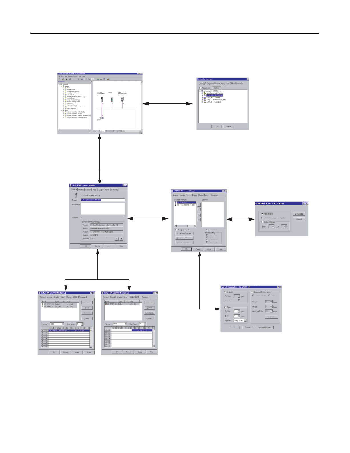
RSNetWorx for DeviceNet Configuration Dialog Map
The main RSNetWorx for DeviceNet dialog.
Double-click the 1747-SDN icon to access the
1747-SDN Interface Module.
Before You Begin 21
Click Online and select the driver
to browse the network.
Click the Scanlist tab to access
the scanlist.
Click Download to Scanner to
download the scanlist.
Select the Input tab and click
AutoMap to automatically
map input devices.
Select the Output tab and click
AutoMap to automatically map
output devices.
Double-click the device in the scanlist to edit a
device’s I/O parameters.
Publication 1747-UM655B-EN-P - June 2007
Page 22

22 Before You Begin
What’s Next?
The remaining sections of this manual provide the following
information:
• Chapter 2 covers the configuration process planning stage
through a data mapping example.
• Chapter 3 describes the hardware setup for the example
application.
• Chapter 4 covers configuration of the DeviceNet network by
using RSNetWorx for DeviceNet software.
• Chapter 5 describes how to configure a DeviceNet network from
another network.
• Chapter 6 describes how to create, download, and run the
example application program.
• Chapter 7 covers the diagnostics provided for troubleshooting
the 1747-SDN module.
• Chapter 8 covers DeviceNet explicit messaging.
• Chapter 9 covers the AutoScan feature.
Publication 1747-UM655B-EN-P - June 2007
Page 23

Chapter
Planning Your Configuration and Data
Mapping Your Devices
2
What This Chapter Contains
What You Need to Know
This chapter introduces questions you should ask before configuring
your 1747-SDN communication module. In addition, it presents an
example DeviceNet network and I/O data mapping scheme for a
photoeye and a RediSTATION operator interface. The following table
identifies what this chapter covers and where to find specific
information.
Topic Page
What You Need to Know 23
Beginning the Process 24
The Example Network 24
What’s Next? 30
To map data via your 1747-SDN communication module, you must
understand the following:
• Network requirements
• Input data mapping
• Output data mapping
23 Publication 1747-UM655B-EN-P - June 2007
Page 24

24 Planning Your Configuration and Data Mapping Your Devices
Beginning the Process
Planning before configuring your 1747-SDN module helps you do
these things:
• Use your memory and bandwidth efficiently
• Cater to device-specific needs and requirements
• Give priority to critical I/O transfers
• Leave room for expansion
You need to know what is on your network. You should be familiar
with each device’s:
• communication requirements.
• I/O importance and size.
• frequency of message delivery.
At this point in your planning, it is advantageous for you to have some
idea of how the network could be expanded. I/O data mapping can
be performed automatically by the RSNetWorx software. But when
mapping your I/O, you also have the opportunity to allot room for
future I/O. This can save time and effort in the future.
For example, RSNetWorx software automatically maps the devices as
efficiently as possible, but the result is that multiple devices may share
the same word location in memory. However, you can also have the
system map the devices such that no two devices share the same
memory location by selecting the Dword align option when
performing automapping. You can also manually map the devices if
you need to assign or reassign them to specific memory locations.
The Example Network
Publication 1747-UM655B-EN-P - June 2007
For details, refer to the Help dialogs provided by the RSNetWorx for
DeviceNet software. Additional support can be found at the Rockwell
Software website: http://www.software.rockwell.com
The following example illustrates a data mapping plan for a
DeviceNet network. Note that even if the mapping is performed
automatically by the RSNetWorx software, you must know where the
devices are mapped in order to use them in your network.
.
Page 25
Planning Your Configuration and Data Mapping Your Devices 25
Example Network Devices
This example network has the following devices:
• A computer running RSNetWorx for DeviceNet software
• A 1747-SDN communication module interfacing an SLC 500
processor with the DeviceNet network
• A Series 9000 photoelectric sensor (strobed)
• A RediSTATION operator interface (polled)
Computer running Windows 2000 or
later operating system, containing
RSNetWorx for DeviceNet software.
IMPORTANT
In the following example, output is data sent to a device from a
controller. Input is data collected from a device by a controller.
The system you set up is shown below.
Example Network
Node 62
Node 0
1770-KFD
Communication
Module
DeviceNet Network
Series 9000
Photoelectric Sensor
Node 9
Node 7
1747-SDN and SLC 500 Processor in
SLC 1746 Chassis
IMPORTANT
RediSTATION Operator Interface
Each end of the DeviceNet trunk cable must be properly
terminated with a resistor. Refer to the DeviceNet Media
Design Installation Guide, publication DNET-UM072, for
detailed information.
Publication 1747-UM655B-EN-P - June 2007
Page 26
26 Planning Your Configuration and Data Mapping Your Devices
RediSTATION Operator Interface Input and Output Data Mapping
The RediSTATION operator interface has both inputs and outputs that
must be mapped. The input byte is mapped to the 1747-SDN module’s
M1 file and then to the SLC 500 processor’s input data file. The output
byte is mapped to the 1747-SDN module’s M0 file and then to the SLC
500 processor’s output data file.
The mapping procedure, using RSNetWorx for DeviceNet software, is
described on page 45.
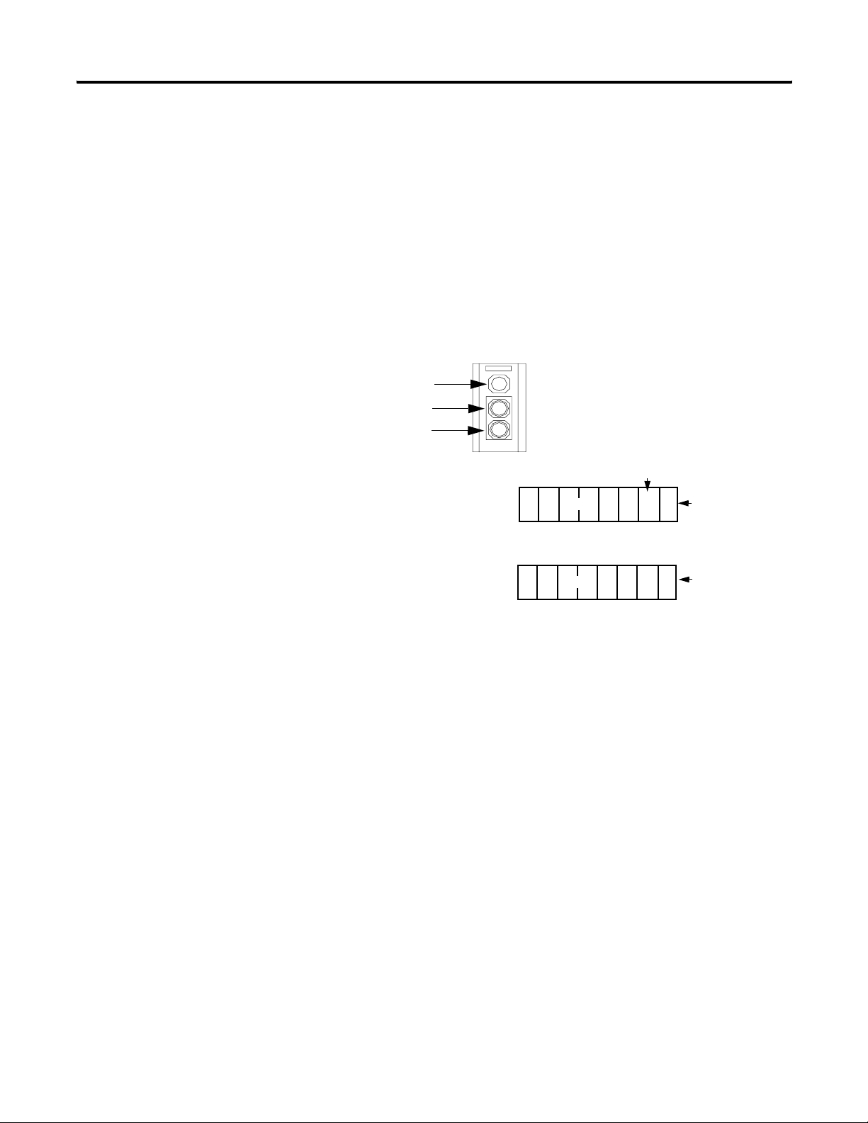
RediSTATION Operator Interface
Indicator Light
Green Start Light
Red Start Light
Two input bits from the RediSTATION
operator interface will be mapped: bit 1 for
the green Start button and bit 0 for the red
Stop button.
Bit 4 of the input byte indicates if the bulb
is missing.
Start Bit (green button)
L
Stop Bit
(red button)
Status Bit for
Indicator Light
The RediSTATION
operator interface
produces one byte of
input data and uses one
byte of output data.
Input
Output
One output bit for the RediSTATION operator
interface’s indicator light (on/off) will be mapped.
1 byte
76543210
1 byte
76543210
G R
In the RediSTATION operator interface’s bits for the red and green
buttons and the indicator light status bit:
• 1 = ON.
• 0 = OFF.
Publication 1747-UM655B-EN-P - June 2007
Page 27
Planning Your Configuration and Data Mapping Your Devices 27
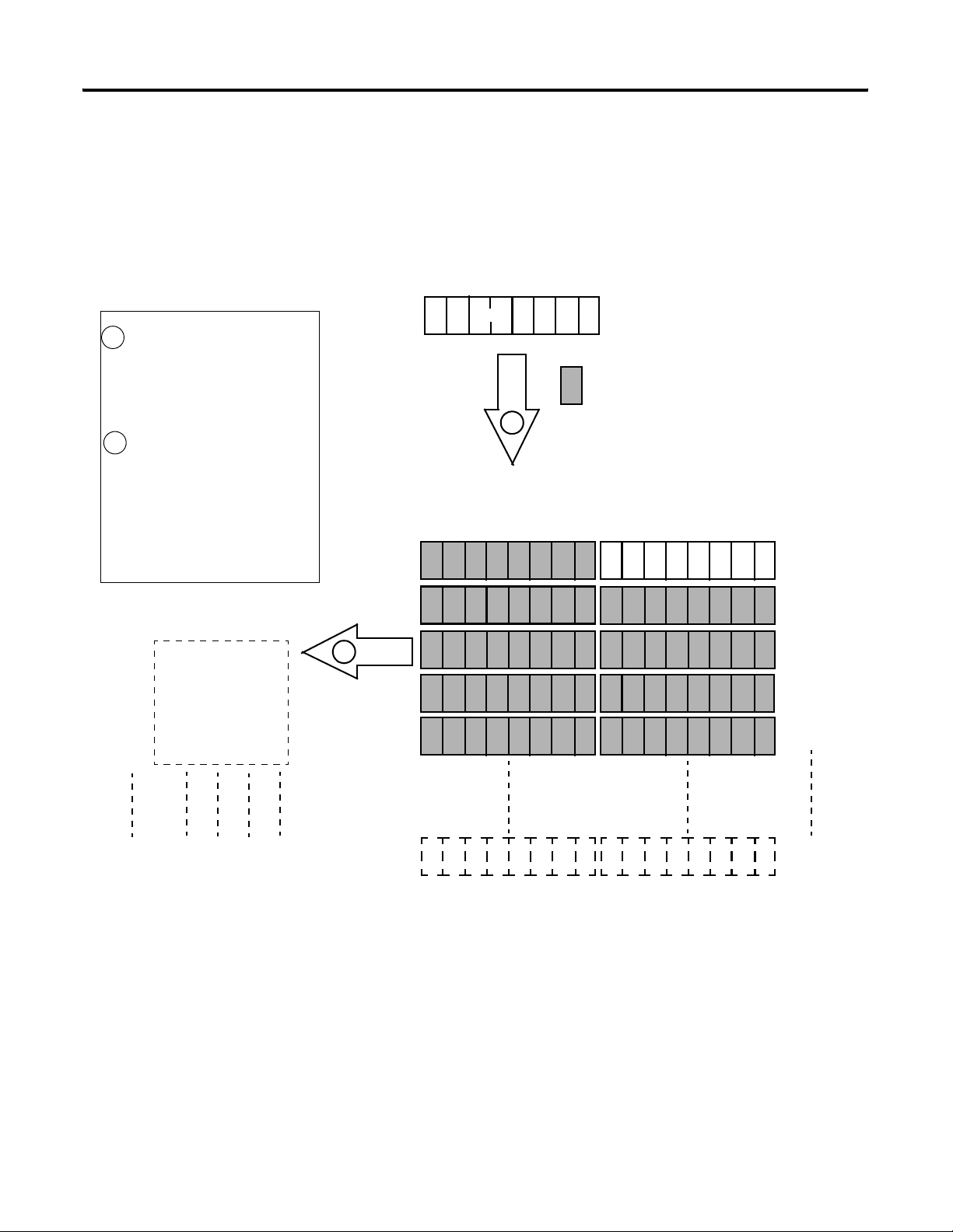
Mapping RediSTATION Input Data for an M1 File Data Table Read
The following is an example of input data mapping for the
RediSTATION operator interface.
RediSTATION Input Byte
What’s Happening?
The bits for the RediSTATION
1
operator interfaces’s red and green
buttons are mapped into the
1747-SDN module’s M1 data table
file.
The M1 file is then transferred to
2
the SLC 500 processor’s input
data file.
Important: The 1747-SDN module only
makes the data file available for the
processor to read. The 1747-SDN
module does not move the data file to
the processor.
SLC 500 Processor
Input Data File1
N7:0
0000 0000 0000 00GR
0000 0000 0000 0000
N7:1
N7:2
0000 0000 0000 0000
0000 0000 0000 0000
N7:3
0000 0000 0000 0000
N7:4
1 byte
1
1747-SDN Module M1 File Data Table
2
G R
R = Bit for Red Button (STOP)
G = Bit for Green Button (START)
= Unused Bits
G R
Word 0
Word 1
Word 2
Word 3
Word 4
N7:149
0000 0000 0000 0000
1
This mapping is based upon the example in
chapters 4 and 6. The mapping for your system
may be different.
Example: The green START button from the
RediSTATION operator interface appears in the
SLC 500 processor’s input file at address
N7:0/1.
Up to
Word 61
The red STOP button from the RediSTATION
operator interface appears in the SLC 500
processor’s input file at address N7:0/0.
Publication 1747-UM655B-EN-P - June 2007
Page 28
28 Planning Your Configuration and Data Mapping Your Devices
Mapping RediSTATION Output Data for an M0 File Data Table
Write
The RediSTATION operator interface’s output is mapped to the
1747-SDN module’s M0 file. Within the output byte is a bit for the
indicator light. The output data file is then transferred from the SLC
500 processor application to turn the light on or off.
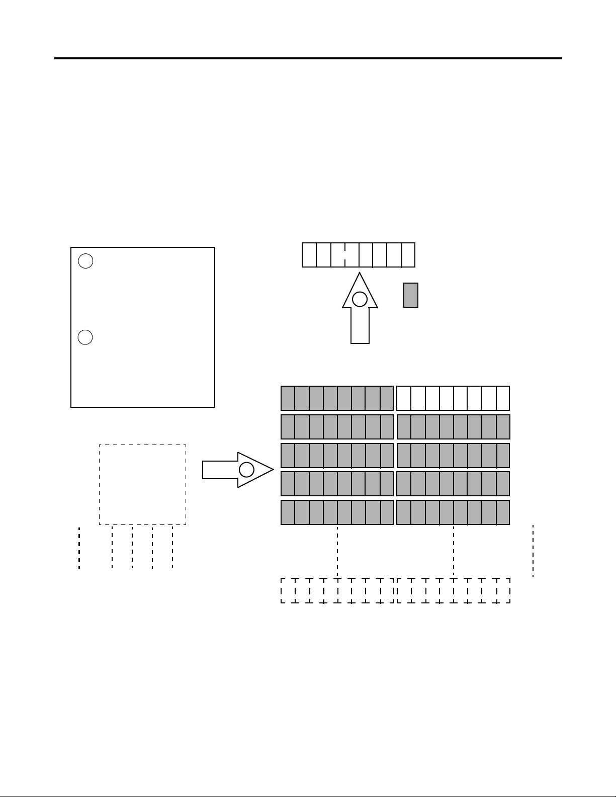
RediSTATION Output Byte
What’s Happening?
The SLC 500 processor’s output
1
data file containing the indicator
light bit for the RediSTATION
operator interface is transferred
to the 1747-SDN Module’s M0
file data table.
2
The M0 file data table is then
sent to the RediSTATION
operator interface via a polled
message from which the
RediSTATION operator interface
receives its indicator light bit.
PLC-5 Processor
Output Data File
N8:0 0000 0000 0000 000L
N8:1 0000 0000 0000 0000
N8:2 0000 0000 0000 0000
N8:3 0000 0000 0000 0000
N8:4 0000 0000 0000 0000
1
Start/Stop Station
1 byte
1747-SDN Module M1 File Data Table
1
Node Address 7
2
L = Fit for the Station
L
Indicator Light
= Unused Bits
L
Word 0
Word 1
Word 2
Word 3
Word 4
N8:149 0000 0000 0000 0000
1
This mapping is based upon the example in chapter 4.
The actual mapping for your system may be different.
Publication 1747-UM655B-EN-P - June 2007
Up to
Word 149
Example: The RediSTATION operator interface’s indicator light (L)
is taken from N8:1/0 in the SLC 500 processor’s output data file.
Page 29
Planning Your Configuration and Data Mapping Your Devices 29
Photoeye Input Data Mapping
The photoelectric sensor (photoeye) inputs are mapped to the
1747-SDN module’s M1 file and then to the SLC 500 processor’s input
data file. The procedure for doing this by using RSNetWorx for
DeviceNet software is described in chapter 4.
The photoeye has no outputs to map.
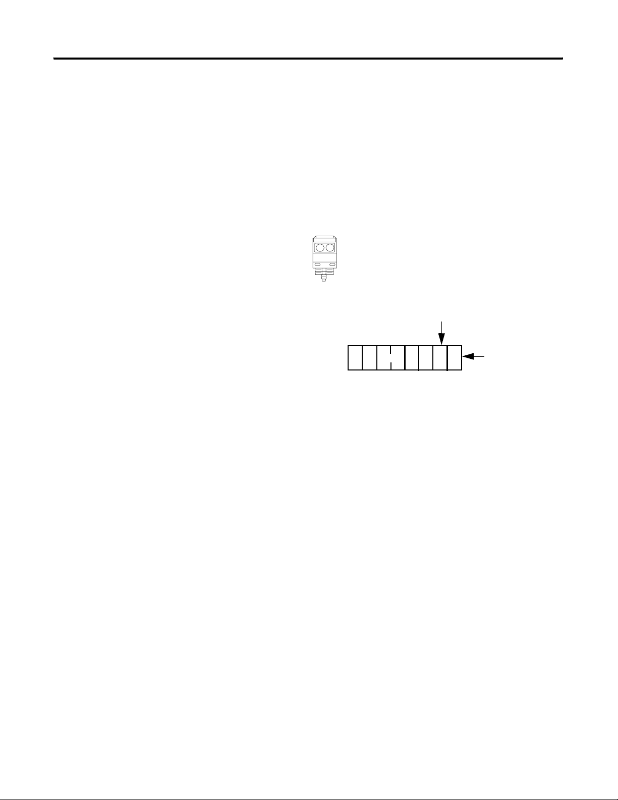
Series 9000 Photoeye
Two input bits from the photoeye
will be mapped: the status bit
and the data bit.
The photoeye produces
one byte of input data in
response to the strobe
message.
Status
Bit
Input
7
1 byte
543
6
2
S D
10
Data
Bit
Publication 1747-UM655B-EN-P - June 2007
Page 30
30 Planning Your Configuration and Data Mapping Your Devices
Mapping Photoeye Input Data for an M1 File Data Table Read
What’s Happening?
The status and data bits from
1
the photoeye are mapped into
the 1747-SDN Module’s M1
file data table.
2
The M1 file data table is then
transferred to the SLC 500
processor’s input data file.
Important: The 1747-SDN module only
makes the data available for the
processor to read. The 1747-SDN
module does not move the data to the
processor.
SLC 500 Processor
Input Data File
N7:0 0000 00SD 0000 0000
N7:1 0000 0000 0000 0000
N7:2 0000 0000 0000 0000
N7:3 0000 0000 0000 0000
N7:4 0000 0000 0000 0000
1
1 byte
1
1747-SDN Module M1 File Data Table
S D
2
S D
= Unused Bits
RediSTATION
Word 0
Word 1
Word 2
Word 3
Word 4
N7:149 0000 0000 0000 0000
1
This mapping is based upon the examples in
chapters 4 and 6. The actual mapping for your system
may be different.
What’s Next?
Publication 1747-UM655B-EN-P - June 2007
Up to
Word 149
Example: The Status bit from the photoeye appears in the SLC 500
processor’s input data file at address N7:0/9.
The Data bit from the photoeye appears in the SLC 500 processor’s
input data file at address N7:0/8.
Chapter 3 describes how to set up the system hardware for the
example application.
Page 31

Hardware Setup
Chapter
3
What This Chapter Contains
Installing the 1770-KFD Module
This chapter describes how to set up the hardware for the example
application. The following table describes what this chapter contains
and where to find specific information.
Topic Page
Installing the 1770-KFD Module 31
Installing the SLC 500 Processor 32
Installing the ControlNet RS-232 Interface
Module
Installing the 1747-SDN Module 40
Installing the RediSTATION Operator
Interface
Installing the Series 9000 Photoeye 44
How Your Network Will Look 45
Connect the RS-232 connector on the 1770-KFD communication
interface module to one of the serial ports on your computer
workstation (COM1). Connect the DeviceNet connector on the
1770-KFD module to a DeviceNet drop or trunk cable. You can make
this connection in several ways; for example, by using a DeviceNet
Quad Tap (catalog number 1492-DN3TW) as shown on page 45.
35
43
To computer COM
1770-KFD RS-232 Interface
Module
DeviceNet Dropline or
Trunk Cable
31 Publication 1747-UM655B-EN-P - June 2007
To DeviceNet Network
Page 32

32 Hardware Setup
For detailed directions on how to install the 1770-KFD module, see
the DeviceNet RS-232 Interface Module Installation Instructions,
publication 1770-5.6.
Installing the SLC 500 Processor
These sections give you information on installing your processor and
getting it connected.
Identifying Processor Features
Refer to the following figures to identify the features of your SLC 5/04
or SLC 5/05 processor.
Processor Features
SLC 5/04 CPU
RUN
FLT
BATT
RUN REM PROG
FORCE
DH+
RS232
Channel 1
DH+
SLC 5/05 CPU
RUN
FLT
BATT
FORCE
ENET
RS232
PROGREMRUN
Channel 1
Ethernet
(10/100Base-T)
Publication 1747-UM655B-EN-P - June 2007
Channel 0
RS232
(optional
DH485, DF1,
or ASCII)
SLC 5/04 Processor
Channel 0
RS232
(optional
DH485, DF1,
or ASCII)
SLC 5/05 Processor
Make sure system power is off; then insert the processor into slot 0 of
the 1746 I/O chassis.
Page 33

Chassis Install
Hardware Setup 33
IMPORTANT
Insert the SLC 500 processor into the left slot (slot 0), as shown
above. Remove the protective wrap after installing the
processor.
Establishing Data Highway Plus Communication
For the examples using the Data Highway Plus (DH+) network in
Chapters 5 and 6 of this manual, we installed a 1784-PKTX
communication card in the host platform and an SLC 5/04 processor
with these default Channel 1 DH+ configurations:
• DH+ node address = 1
• Communication rate = 57.6 Kbps
Connect Channel 1 of the SLC 5/04 processor to the DH+ network by
using the three-pin connector on the front of the module.
Publication 1747-UM655B-EN-P - June 2007
Page 34

34 Hardware Setup
DH+ Network Connection
Terminating
Resistor
See Chapter 5 for information on configuring the SLC 5/04 processor’s
DH+ communication.
Installing an Ethernet SLC 500 Processor (SLC 5/05 Processor)
In order to communicate with your SLC 500 processor over an
Ethernet network, you must install an Ethernet version of the
processor (SLC 5/05 processor, catalog numbers 1747-L551, 1747-L552,
or 1747-L553).
Connect channel 1 of the Ethernet SLC 5/05 processor to an Ethernet
hub by using 10 Base-T cable as shown below.
Ethernet Hub Connection
Ethernet
Hub
to Host Platform
Ethernet Card
RJ45 Connectors on Both
Ends of Cable (10Base-T)
to SLC 5/05
Channel 1
Publication 1747-UM655B-EN-P - June 2007
See Chapter 5 for information on configuring the SLC 5/05 processor’s
Ethernet communication.
Page 35

Hardware Setup 35
Configuring the RS-232 Port for the ControlNet Interface
If you need to communicate with your SLC 500 processor via a
ControlNet network, you must install a 1747-KFC15 ControlNet
interface module in the chassis with your processor. You can use
either a SLC 5/04 or a SLC 5/05 processor. The 1747-KFC15 module
connects to the SLC 500 processor via the processor’s RS-232 port
(channel 0).
Installing the ControlNet RS-232 Interface Module
TIP
To communicate with the SLC 500 processor via a ControlNet
network, you must install a 1747-KFC15 ControlNet RS-232 interface
module in the 1746 I/O chassis close to the processor.
You can use your RSLogix 500 programming software to set the
SLC 5/04 processor’s RS-232 channel configuration.
Configuring the 1747-KFC15 Module’s RS-232 Port
IMPORTANT
The RS-232 serial port on the 1747-KFC15 module is configured by
using three banks (S1, S2, and S3) of DIP switches mounted on the
module’s printed circuit board.
The communication parameters of 1747-KFC15 module must
match those of the SLC 500 processor.
Publication 1747-UM655B-EN-P - June 2007
Page 36

36 Hardware Setup
Dip Switch Setting
The upper position as shown above is
ON. The lower position is OFF.
For the example application, we used the following configuration to
match the configuration of the SLC 500 processor’s RS-232 port
described in the previous section.
Channel 0 Configuration
Attribute Value
DF1 station address 0
Communication rate 19.2 Kbps
Full/Half-duplex Full-duplex
Parity None
Handshake No handshaking
Diagnostic command execution Disabled
Duplicate detect Enabled
Error detect CRC
Retries 3
DF1 ACK timeout 1.0 s
For this configuration, set the switches as shown in these tables.
Publication 1747-UM655B-EN-P - June 2007
Page 37

Bank S1 DIP Switches
Switch Setting Position
Switches
1…3
Upper digit
of DF1
station
SW1 SW2 SW3 Digit
ON ON ON 0
address
Hardware Setup 37
Switches
4…6
Lower digit
of DF1
station
SW4 SW5 SW6 Digit
ON ON ON 0
address
Switches 7…8 Both OFF
Bank S2 DIP Switches
Switch Setting Position
Switches
1…3
Upper digit
of DF1
station
SW1 SW2 SW3 Digit
ON OFF OFF 19200
address
Switch 4 Full/Half-dup
OFF = Full-duplex
lex
Switch 5 Parity OFF = No parity
Switch 6 Odd/even
Not applicable
parity
Switch 7 Handshake OFF = Hardware handshake disabled
Switch 8 Diagnostic
OFF = Disabled
command
execution
Bank S3 DIP Switches
Switch Setting Position
Switch 1 Duplicate
ON = Duplicate detect on
detect
Switch 2 Error
OFF = CRC error check
detect
Switches
3…4
Switches
5…8
Number of
retries
DF1 ACK
time-out
SW3 SW4 Number of retries
ON ON 0
SW5 SW6 SW7 SW8 Time Out
OFF OFF OFF OFF 3.2
Publication 1747-UM655B-EN-P - June 2007
Page 38

38 Hardware Setup
Refer to the SLC 500 ControlNet RS-232 Interface User Manual,
publication 1747-5.34, for information on setting and verifying the
1747-KFC15 and SLC 500 processor communication parameters.
Configuring the 1747-KFC15 Module’s ControlNet Node Address
The 1747-KFC15 modules’s ControlNet node address is set by rotary
switches S4 and S5 on the top of the module. Switch S5 sets the upper
digit of the address and S4 the lower. These switches can be turned by
hand while holding the module in the orientation illustrated below.
Switch Location
Back of
Module
Rotary Switches
S4
S4
S5
S5
Front of
Module
We set the ControlNet node address to 16 for the example application.
Switch Setting
ControlNet Node Address = 16
2
20
30
10
00
90
80
40
50
60
70
1
0
9
3
4
5
6
7
8
Refer to Chapter 5 for more information on configuring ControlNet
communication for the example application.
Publication 1747-UM655B-EN-P - June 2007
Page 39

Install the 1747-KFC15 Module in the Chassis
Hardware Setup 39
ATTENTION
Electrostatic discharge can damage semiconductor devices
inside the 1747-KFC15 module. To guard against electrostatic
damage, wear an approved wrist strap grounding device, or
touch a grounded object to rid yourself of electrostatic charge
before handling the products.
1. Remove power from your 1746 I/O chassis.
2. Install the 1747-KFC15 module into an empty I/O slot.
The 1747-KFC15 module must be placed near enough to the SLC
processor to connect the supplied RS-232 cable between them.
We used slot 1 for the example application.
3. Connect the 1747-KFC15 module to your SLC 500 processor with
the RS-232 cable.
RS-232 Cable
Connecting the 1747-KFC15 Module to the ControlNet Network
Connect the 1747-KFC15 to the ControlNet cable system by using an
approved ControlNet tap.
Publication 1747-UM655B-EN-P - June 2007
Page 40

40 Hardware Setup
Refer to the ControlNet Coax Media Planning and Installation Guide,
publication CNET-IN002, for complete instructions on connecting the
tap to the ControlNet cable system.
Installing the 1747-SDN Module
These sections give you information on installing your module and
getting it connected.
Identifying Module Features
Use the following figure to identify the features of the 1747-SDN
module.
1747-SDN Module Features
Module Status Indicator
indicates module status.
Node Address and Status
Display displays numeric codes
and indicates scanner node
address or error.
Network Status Indicator
indicates status of the DeviceNet
channel communication link.
Access Door
Publication 1747-UM655B-EN-P - June 2007
Wiring Color
Codes
10-pin Linear Plug
inserted into
DeviceNet port.
Page 41

Install the 1747-SDN Module In the Chassis
Hardware Setup 41
ATTENTION
Do not install the 1747-SDN module with the chassis power
supply on. Installing the module with the chassis power supply
on may damage the module.
Follow these steps to install your module into the chassis.
1. Turn off the chassis power supply.
2. Select a slot for the module in the chassis.
You may use any slot except the leftmost slot, which is reserved
for the SLC 500 processor.
3. Insert the module into the slot you have selected by applying
firm, even pressure to seat the module in the chassis backplane
connectors.
Publication 1747-UM655B-EN-P - June 2007
Page 42
42 Hardware Setup
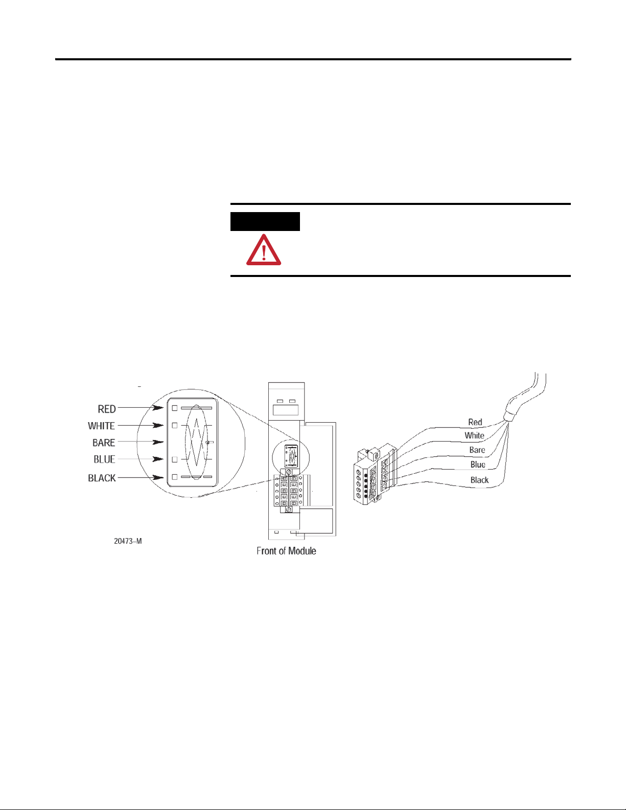
Connect the 1747-SDN Module to the DeviceNet Network
Follow these steps to connect your module to the DeviceNet network.
1. Turn off the network power supply.
Module label shows wiring
color scheme.
ATTENTION
Do not wire the 1747-SDN module with the network power
supply on. Wiring the module with the network power supply
on may short your network or disrupt communication.
2. Connect the DeviceNet drop line to the 10-pin linear plug.
Match the wire insulation colors to the colors shown on the
label.
10-pin
Linear Plug
DeviceNet
Drop Line
Publication 1747-UM655B-EN-P - June 2007
3. Locate the DeviceNet port connector on the front of the module,
and insert the 10-pin linear plug into the connector.
Page 43

Hardware Setup 43
Installing the RediSTATION Operator Interface
TIP
You use RSNetWorx for DeviceNet software to configure the
module’s DeviceNet address and communication rate, if
needed. This is done when configuring the DeviceNet network.
See page 52.
For additional information about installing the 1747-SDN module, see
the 1747-SDN DeviceNet Scanner Module Installation Instructions,
publication 1747-IN058.
Begin installing the RediSTATION operator interface by removing the
six screws fastening the cover and setting the DIP switches inside.
DIP Switch Settings
Set this position To this value
1
2
3
4
5
6
7
8
9
10
(1)
The DeviceNet address is 000111 (node 7).
(2)
The data rate is 10 (500 KB). The output fault rate is 0 (outputs turned off). The output
flash rate is 0 (outputs tuned off).
1 - On
1 - On
1 - On
0 - Off
0 - Off
0 - Off
0 - Off
1 - On
0 - Off
0 - Off
Node
Address
Data Rate
(1)
(2)
Publication 1747-UM655B-EN-P - June 2007
Page 44

44 Hardware Setup
See Chapter 2 of the RediSTATION Operator Interface User Manual,
publication 2705-UM001, for complete information about setting the
DIP switches to configure the node address, data rate, output flash
rate, and output fault state.
Refer to the following illustration as you connect the RediSTATION
operator interface to the network.
TIP
You do not need to disconnect incoming power from the
DeviceNet network before connecting the RediSTATION
operator interface.
The DeviceNet cable connects directly to the mini connector on the
top of the RediSTATION enclosure or through the conduit opening
(open style).
RediSTATION Connection
DeviceNet
Cable
Mini
Connector
Open
Style
Installing the Series 9000 Photoeye
Publication 1747-UM655B-EN-P - June 2007
Connect the photoeye to the network and configure the photoeye as
follows:
• Node address: 9
• Operating mode: Light Operate (default)
• Communication rate: 500 Kbps
Page 45
Hardware Setup 45
Top View of Series 9000 Photoeye
Programming
Pushbutton
Sensitivity
Adjustment
Yellow - Output
Green - Margin
Red/Green - Status
For detailed directions, see the instructions that came with your
photoeye.
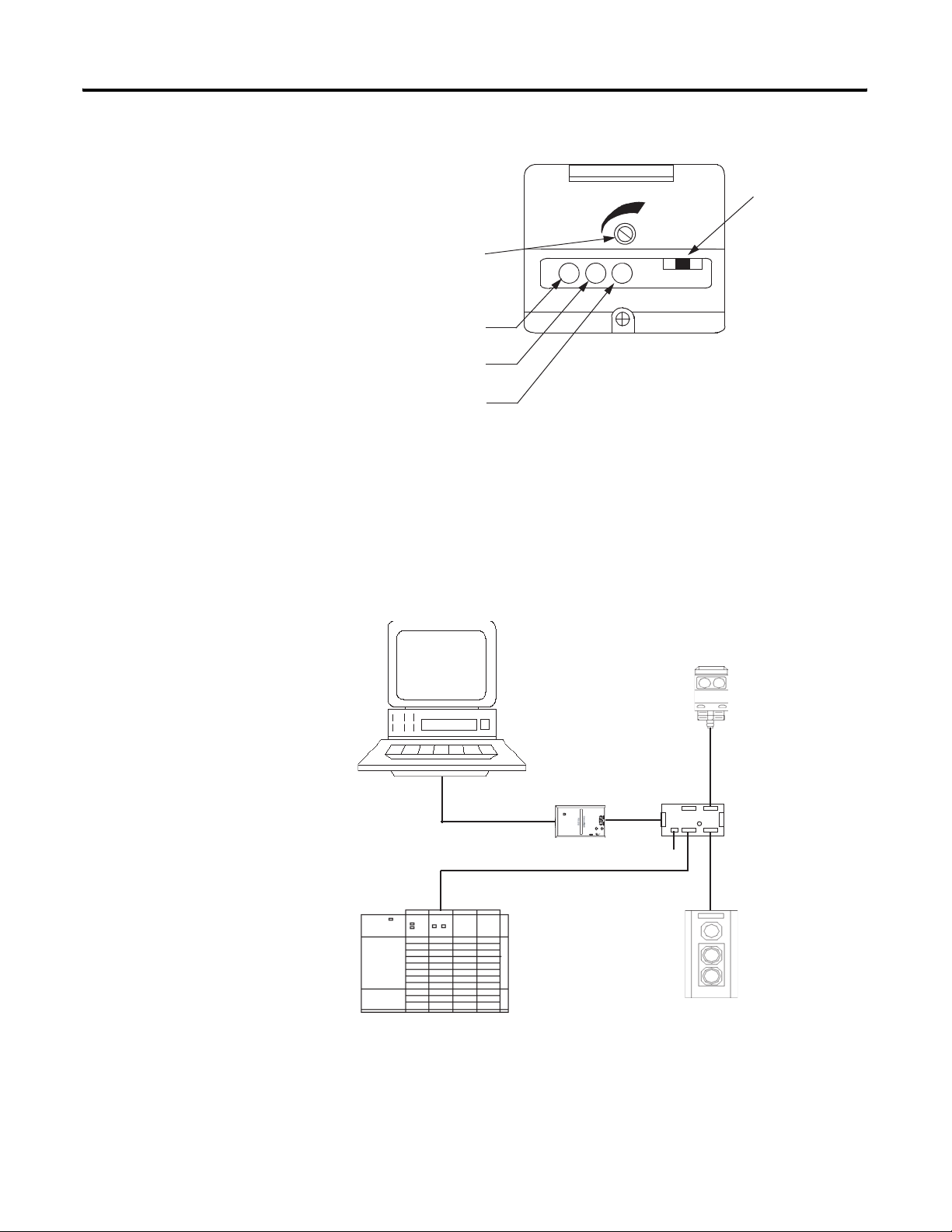
How Your Network Will Look
Computer running Windows 2000 or
later operating system, containing
RSNetWorx for DeviceNet software.
SLC 500 Chassis
When you have finished installing all the devices, the network should
look similar to this.
Typical Network
Series 9000
Photoelectric Sensor
Node 9
Quad-tap
1492-DN3TW
Node 7
Computer Serial
Port
Node 0
1770-KFD
Communication
Module
Node 62
24 V
RediSTATION
Operator Interface
Publication 1747-UM655B-EN-P - June 2007
Page 46

46 Hardware Setup
What’s Next?
IMPORTANT
The next step is to configure the 1747-SDN module and perform I/O
data mapping through RSNetWorx for DeviceNet software.
Make sure each end of the DeviceNet trunk cable is properly
terminated with a resistor. Refer to the DeviceNet Media
Design and Installation Guide, publication DNET-UM072, for
information.
Publication 1747-UM655B-EN-P - June 2007
Page 47

Chapter
Configuring the DeviceNet Network
4
What This Chapter Contains
This chapter describes how to configure the DeviceNet network by
using RSLinx and RSNetWorx for DeviceNet software.
Topic Page
Installing the Software 47
Use RSLinx Software to Configure the DeviceNet Driver 48
Using RSNetWorx for DeviceNet Software to Configure the 1747-SDN
Module Scanlist
Set Up an Online Connection 50
Set the 1747-SDN Node Address 52
Configure the I/O Devices 55
Verify the Photoeye Configuration 57
Verify the RediSTATION Configuration 57
AutoMap the Devices into the Scanlist 58
Download and Save Your Configuration 62
50
Installing the Software
47 Publication 1747-UM655B-EN-P - June 2007
Follow these steps to install the RSLinx and RSNetWorx for DeviceNet
software.
1. Insert the software CD-ROM in the drive.
The CD-ROM supports Windows Autorun. If you have Autorun
configured, the installation automatically starts when you insert
the CD-ROM in your drive. If you do not have Autorun
configured, perform steps 2 and 3.
2. Select Run from the Windows Start menu.
3. Browse for the Setup program on the CD ROM and open it.
4. Follow the prompts that appear as you install the software.
After software installation is complete, you use RSLinx software to
configure your DeviceNet driver and RSNetWorx for DeviceNet
software to configure the network.
Page 48

48 Configuring the DeviceNet Network
Use RSLinx Software to Configure the DeviceNet Driver
Follow these steps to configure your DeviceNet driver.
1. Start RSLinx software.
The RSLinx main dialog opens.
2. Select Configure Drivers from the Communication menu.
The following dialog appears.
Publication 1747-UM655B-EN-P - June 2007
3. Select DeviceNet Drivers from the above pull-down menu and
click Add/New.
You see the following choices.
Page 49

Configuring the DeviceNet Network 49
4. Select the Allen-Bradley 1770-KFD driver.
The Driver Configuration dialog appears.
TIP
Your driver setup depends on your particular system setup
(COM port, communication rate, node address). Choose
the appropriate settings for your system.
5. Configure the driver by using the example above as a guide and
click on OK.
The software takes a few seconds to configure the driver. When
it is done the following prompt appears.
6. Select the default driver name 1770-KFD-1 and click OK.
7. Close RSLinx software.
Use the driver you just configured to browse and configure the
network with RSNetWorx for DeviceNet software.
Publication 1747-UM655B-EN-P - June 2007
Page 50

50 Configuring the DeviceNet Network
Using RSNetWorx for DeviceNet Software to Configure the 1747-SDN Module Scanlist
Use RSNetWorx for DeviceNet software to do the following tasks:
• Set up an online connection
• Set the 1747-SDN node address
• Configure the I/O devices
• Download and save your configuration
Set Up an Online Connection
Follow these steps to set up an online connection to the DeviceNet
network by using the 1770-KFD driver.
1. Start RSNetWorx for DeviceNet software.
The following dialog appears.
Publication 1747-UM655B-EN-P - June 2007
2. From the File menu, choose New.
If you have a ControlNet network configured on your system
you may see the following dialog. Otherwise, proceed to step 4.
3. Highlight DeviceNet Configuration and click OK.
Page 51

Configuring the DeviceNet Network 51
4. Click Online on the toolbar.
A list of the available drivers in RSLinx software appears. Your
list may appear different from that shown below, depending
upon the drivers you have configured on your system.
5. Select the 1770-KFD-1, DeviceNet driver and click OK.
You are prompted to upload or download devices before going
online.
Publication 1747-UM655B-EN-P - June 2007
Page 52

52 Configuring the DeviceNet Network
6. Click OK to upload the devices and go online.
RSNetWorx for DeviceNet software begins browsing for network
devices. When the software is done browsing, the network
displayed on your screen should appear similar to the one
shown below.
TIP
RSNetWorx for DeviceNet software performs a one-shot
browse when you go online or choose the browse feature. The
software polls for devices one time and displays the results. If
a node which was online later goes offline, there is no live
indication in RSNetWorx for DeviceNet software. You must
manually perform a browse to detect the missing node.
To manually perform the browse, press the button.
TIP
If RSNetWorx for DeviceNet software fails to find a device,
check the physical connection to the device. If the physical
connection is intact, verify that the device’s communication rate
is the same as the 1770-KFD driver’s communication rate.
Set the 1747-SDN Node Address
Once the devices are uploaded, their node addresses appear to the
right of their icons. For the example application, the 1747-SDN
module should have a node address of 0 (or 00). If you need to
change a module’s node address, use the following procedure.
Publication 1747-UM655B-EN-P - June 2007
TIP
You can use this procedure to change the node address of
other devices on the network (for example, the photoeye).
You can also change the network data rate (communication
rate) of some devices. Power must be cycled for baud rate
changes to take effect.
Page 53
Configuring the DeviceNet Network 53
If 00 appears to the right of the 1747-SDN icon and you do not need
to change the node address or baud rate of any device, skip the
remainder of this section and go to Configure the I/O Devices on
page 55.
IMPORTANT
The network must not be active when performing node
commissioning on the 1747-SDN module. Make sure the
processor is in Program mode.
(Note that this applies only to the 1747-SDN module. You may
commission other devices with the processor in Run mode.)
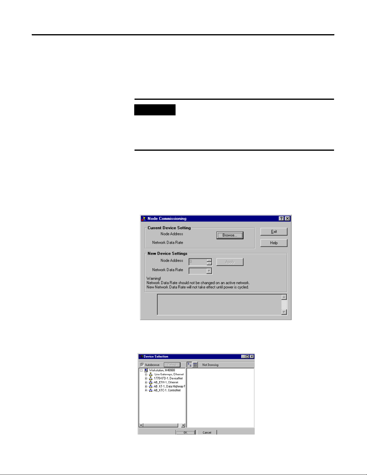
Follow these steps to set the node address.
1. From the Tools menu, choose Node Commissioning.
The Node Commissioning dialog appears.
2. Click Browse.
The Device Selection dialog appears.
Publication 1747-UM655B-EN-P - June 2007
Page 54

54 Configuring the DeviceNet Network
3. Select the 1770-KFD driver.
The devices on the network appear in the right panel of the
dialog.
4. Select the device you are commissioning in the right panel and
click OK.
The Node Commissioning dialog appears with the current
settings for your 1747-SDN module. Your dialog should look
similar to the one shown below.
Publication 1747-UM655B-EN-P - June 2007
5. Enter a 0 in the New Device Settings: Node Address box.
6. Click Apply and exit the dialog.
Page 55

Configuring the DeviceNet Network 55
Configure the I/O Devices
Follow these steps to configure the I/O devices.
1. Double-click the 1747-SDN module icon.
The following dialog appears.
2. Click the Module tab.
You receive the following prompt.
Publication 1747-UM655B-EN-P - June 2007
Page 56

56 Configuring the DeviceNet Network
3. Click Upload.
After uploading, the following dialog appears.
4. Verify the 1747-SDN module slot number is correct for your
system.
We used slot 2.
TIP
We used the Module Defaults for the other settings. For an
explanation of these settings click Help.
5. Select the Scanlist tab.
Publication 1747-UM655B-EN-P - June 2007
6. Verify that the Automap on Add box is not checked.
Page 57

Configuring the DeviceNet Network 57
7. Click the double arrow to add the photoeye and
RediSTATION operator interface to the Scanlist.
Verify the Photoeye Configuration
1. Double-click the photoeye in the Scanlist.
The Edit I/O Parameters dialog appears for the photoeye.
The I/O parameters define the configuration for the device in
terms of how much and what data the device exchanges with
the 1747-SDN module. By default, the photoeye will send 1 byte
when it receives the strobe request.
2. Verify that the photoeye parameters are set as shown above.
3. Click OK to close the photoeye Edit I/O Parameters dialog.
Verify the RediSTATION Configuration
1. Double-click the RediSTATION operator interface in the Scanlist
dialog.
Publication 1747-UM655B-EN-P - June 2007
Page 58

58 Configuring the DeviceNet Network
The Edit I/O Parameters dialog appears for the RediSTATION
operator interface.
2. Verify that the Polled box is checked and that the Rx Size and Tx
Size are each 1 byte.
3. Click OK to close the Edit I/O Parameters dialog for the
RediSTATION operator interface.
4. Click OK again.
You are prompted to download the changes to the 1747-SDN
module.
5. Click Yes to download the new configuration.
AutoMap the Devices into the Scanlist
Follow these steps to automatically map the photoeye and
RediSTATION operator interface to the SLC 500 processor.
Publication 1747-UM655B-EN-P - June 2007
TIP
If you want to know how to map the devices manually, click
Help at the bottom of the dialog and select Map device input
data manually.
Page 59

Configuring the DeviceNet Network 59
1. Double-click the 1747-SDN module icon and select the Input
tab.
2. Select M File in the Memory field.
3. Highlight the RediSTATION operator interface and the photoeye
and click AutoMap.
The resulting device mapping appears in the lower panel.
Photoeye
inputs
RediSTATION
inputs
In this example, the inputs from the RediSTATION operator
interface appear in the M1 file for the device in slot 2 as word 0,
bits 0…7.
Publication 1747-UM655B-EN-P - June 2007
Page 60

60 Configuring the DeviceNet Network
Recall from Chapter 2 that the START button is bit 1 and the
STOP button is bit 0. Therefore, the addresses for the
RediSTATION inputs are:
START - M1:2.0.1
STOP - M1:2.0.0
The input from the photoeye appears in the M1 file for the
device in slot 2 as word 0, bits 8…15.
Recall from chapter 3 that the input bit is bit 0. Therefore, the
address of the photoeye input is:
M1:2.0.8
4. Note the addresses assigned to the START and STOP buttons
and the photoeye in your system.
You enter these addresses in the example ladder program.
Publication 1747-UM655B-EN-P - June 2007
Page 61
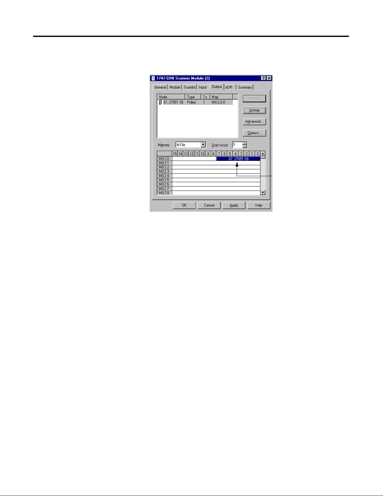
5. Select the Output tab.
Configuring the DeviceNet Network 61
After mapping, the
RediSTATION output
address appears
here.
6. Select M File in the Memory field.
7. Highlight the RediSTATION operator interface and click
AutoMap.
In this example, the output to the RediSTATION operator
interface appears in the M0 file for the device in slot 2 as word
0, bits 0…7. Recall from Chapter 3 that the indicator light is
output bit 0. Therefore, the address for the RediSTATION
indicator light is:
M0:2.0.0
8. Note the address assigned to this output in your system.
You enter this address in the example ladder logic program in
the following chapter.
Publication 1747-UM655B-EN-P - June 2007
Page 62

62 Configuring the DeviceNet Network
Download and Save Your Configuration
1. Click the Scanlist tab and then Download to Scanner.
2. Select All Records.
3. Click Download to download the configuration to the 1747-SDN
module.
4. Click OK to complete the DeviceNet scanner configuration.
What’s Next?
5. From the File menu, choose Save As.
6. Save the configuration to a DeviceNet file.
7. Close the RSNetWorx for DeviceNet software.
The next chapter describes how to configure the DeviceNet network
remotely from an Ethernet, ControlNet, or Data Highway Plus
network.
Publication 1747-UM655B-EN-P - June 2007
Page 63

Chapter
5
Communicating with the DeviceNet Network
from Another Network
What This Chapter Contains
This chapter describes how to communicate with the DeviceNet
network from another network, by using the SLC 500 pass-through
feature. This feature can be used to adjust and fine tune the nodes on
your network. Examples are provided for communicating from an
Ethernet network and a Data Highway Plus network.
ATTENTION
The following table describes what this chapter contains and where to
find specific information.
The pass-through feature is not intended to replace a
1770-KFD, 1770-PCD, 1770-PCID, or 1770-PCIDS connection to
the network.
Pass-through is intended only for fine tuning and adjustment of
your network devices. Do not attempt to configure your entire
network by using a pass-through driver or a time-out may occur.
The pass-through method is not suitable for real-time
monitoring of your network devices.
Topic Page
Additional Resources 64
System Requirements 64
Communicating with the DeviceNet
Network via an Ethernet Network
Communicate with the DeviceNet Network
via a DH+ Network
What’s Next? 78
63 Publication 1747-UM655B-EN-P - June 2007
65
73
Page 64

64 Communicating with the DeviceNet Network from Another Network
Additional Resources
These documents contain additional information on configuring other
networks.
Resource Description
SLC Modular Style Hardware Installation and Operation Manual,
publication 1747-UM011
Ethernet SLC 500 Processors Quick Start for Experienced Users,
publication 1747-10.4
Comer, Douglas E., Internetworking with TCP-IP, Volume 1: Protocols
and Architecture, 2nd ed. Englewood Cliffs, N.J.:Prentice-Hall,
1995. ISBN 0-13-216987-8
Tannebaum, Andrew S. Computer Networks, 2nd ed. Englewood
Cliffs, N.J.: Prentice-Hall, 1989. ISBN 0-13-162959-X
Provides information about the Data Highway Plus network.
Provides information about the Ethernet interface.
Provides information about TCP/IP protocol and networking in
general.
You can view or download publications at
http://literature.rockwellautomation.com
technical documentation, contact your local Rockwell Automation
distributor or sales representative.
. To order paper copies of
System Requirements
To use the pass-through feature, you must have RSLinx software,
version 2.10 or later, and a 1747-SDN module at firmware revision
4.015 or later.
IMPORTANT
To enable pass-through access with a SLC 500 processor, you
must use RSLogix 500 software to configure the M0 and M1
files associated with the 1747-SDN module with a length of
395 words. You can access the M file configuration by
launching I/O Configuration within RSLogix 500 software, and
then selecting the 1747-SDN module.
The SLC 500 processor must be placed in Run mode at least
once since its last power cycle for 1747-SDN pass-through
transactions to succeed.
IMPORTANT
You must have previously set up the network you will use to
communicate with the DeviceNet network and have installed
and configured the appropriate drivers and interface hardware.
Publication 1747-UM655B-EN-P - June 2007
Page 65

Communicating with the DeviceNet Network from Another Network 65
The SLC 500 chassis used for these examples was set up with the
following hardware mapping. The SLC 5/04 processor was used for
the DH+ example. The SLC 5/05 processor was used for the Ethernet
example.
Hardware Mapping
Communicating with the DeviceNet Network via an Ethernet Network
Module Slot DH+
Address
SLC 500 5/04
Processor
SLC 500 5/05
Processor
1747-SDN 2 - - 0
01- -
0 - 130.130.130.2 -
Ethernet
Address
DeviceNet
Address
Before performing this example, the Ethernet network must be
configured and running. You must use an Ethernet SLC 5/05 processor
(catalog number 1747-L551, 1747-L552, or 1747-L553).
Establishing Ethernet pass-through communication involves four main
steps.
1. Configure the Ethernet to SLC-5 driver to communicate with the
SLC 5/05 processor over the Ethernet Network by using RSLinx
software.
This procedure is described starting on page 66.
2. Configure the DeviceNet pass-through driver to communicate
with the 1747-SDN module via the SLC 5/05 processor and the
Ethernet network by using RSLinx software.
This procedure is described starting on page 68.
3. Configure the SLC 5/05 processor’s Ethernet communication
channel by using RSLogix 500 software when you create the
example ladder program.
The Ethernet channel configuration is described in Appendix B.
4. Use the pass-through driver with RSNetWorx for DeviceNet
software to adjust and tune your DeviceNet network.
The procedure for doing this is described starting on page 73.
Publication 1747-UM655B-EN-P - June 2007
Page 66

66 Communicating with the DeviceNet Network from Another Network
Configure the Ethernet Devices Driver
To communicate with your SLC 500 processor over the Ethernet
network you must configure the Ethernet to SLC 500 driver. Follow
these steps to configure the driver by using RSLinx software.
1. Start RSLinx software.
2. From the Communication menu, choose Configure Drivers.
The Configure Drivers dialog appears.
3. From the Available Driver Types pull-down menu, select
Ethernet to PLC-5/SLC-5/5820-E and click Add New.
Publication 1747-UM655B-EN-P - June 2007
Page 67

Communicating with the DeviceNet Network from Another Network 67
You are prompted to choose a name for the new driver.
4. Enter an appropriate driver name (for example, AB_ETH-1) and
click OK.
The Configure driver for Ethernet to PLC-5/SLC-5/5820-EI dialog
opens.
5. Enter the IP address of the SLC 5/05 processor in the IP address
or hostname field (130.130.130.2 in this example).
IMPORTANT
You must configure channel 0 of the SLC 5/05 processor with
the same IP address you enter here.
Publication 1747-UM655B-EN-P - June 2007
Page 68

68 Communicating with the DeviceNet Network from Another Network
6. Click Accept and then OK.
The new driver is added to the list of Configured Drivers in
RSLinx software. (Your list contains the drivers you have
configured.)
Configure the DeviceNet Network Pass-through Driver
Before you can communicate with the 1747-SDN module via the
Ethernet network, you must configure the DeviceNet pass-through
driver (catalog number 1747-SDNPT) by using RSLinx software,
version 2.10 or later. You must also have configured the Ethernet to
PLC-5/SLC-5/5820-EI driver as described in the previous section and
configured the SLC 5/05 processor’s Ethernet communication channel
as described in Appendix B.
Follow these steps to configure the DeviceNet network Pass-through
driver.
1. Start RSLinx software.
Publication 1747-UM655B-EN-P - June 2007
Page 69

Communicating with the DeviceNet Network from Another Network 69
2. From the Communication menu, choose Configure Driver.
The Configure Drivers dialog appears.
3. From the Available Driver Types pull-down menu, select
DeviceNet Drivers and click Add New.
The following list of drivers appears.
4. Select the Allen-Bradley 1747-SDNPT driver.
The Allen-Bradley 1747-SDNPT Driver Configuration dialog
opens.
5. From the 1747-SDN Slot pull-down menu, select a pass-through
port to be configured, for example Slot 2.
6. Expand your Ethernet driver (AB_ETH-1) and highlight the
SLC 5/05 processor.
7. Verify that the 1747-SDN Slot is correct.
Publication 1747-UM655B-EN-P - June 2007
Page 70

70 Communicating with the DeviceNet Network from Another Network
8. Click OK.
You are prompted to enter a name for the driver.
9. Enter an appropriate driver name (for example, 1747-SDNPT-2)
and click OK.
The new driver is added to the list of Configured Drivers in
RSLinx software. (Your list contains the drivers you have
configured for your system.)
10. Close or minimize RSLinx software.
Communicate with the DeviceNet Network
You can use RSNetWorx for DeviceNet software to communicate with
the DeviceNet network via the Ethernet network once the Ethernet
pass-through driver is configured.
Follow these steps to communicate with the DeviceNet network.
Publication 1747-UM655B-EN-P - June 2007
Page 71

Communicating with the DeviceNet Network from Another Network 71
1. Start RSNetWorx for DeviceNet software.
2. From the File menu, choose New.
You may see the following dialog if you have the ControlNet
network configured on your system. Otherwise, proceed to
step 4.
3. Select DeviceNet Configuration and click OK.
4. Click Online on the toolbar.
Publication 1747-UM655B-EN-P - June 2007
Page 72

72 Communicating with the DeviceNet Network from Another Network
The Browse for network dialog appears. You see the drivers you
have configured on your system.
5. Highlight 1747-SDNPT-2, DeviceNet driver and click OK.
You receive the following prompt.
6. Click OK to upload the devices.
RSNetWorx for DeviceNet software begins browsing for network
devices.
ATTENTION
Performing a pass-through browse via the Ethernet network
takes longer than browsing by using the 1770-KFD DeviceNet
driver as described in chapter 4.
Note that due to the time required, the pass-through method is
not suitable for configuring a network nor for real time
monitoring of your network devices.
The network displayed on your screen should look similar to the
one shown below when RSNetWorx for DeviceNet software is
finished browsing.
Publication 1747-UM655B-EN-P - June 2007
TIP
If RSNetWorx for DeviceNet software fails to find a device,
check the physical connection to that device.
Page 73

Communicating with the DeviceNet Network from Another Network 73
You are now online to the DeviceNet network via the Ethernet
network.
See pages 55…62 of this manual for examples of how to use
RSNetWorx for DeviceNet software to adjust network
parameters.
Communicate with the DeviceNet Network via a DH+ Network
Before performing this example, the DH+ network must be
configured and running. This example uses a SLC 5/04 processor. The
SLC 5/04 processor lets you operate DH+ communication protocol by
means of DH+ communication channel 1.
Configure the DeviceNet Pass-through Driver
You must first configure the DeviceNet pass-through driver (catalog
number 1747-SDNPT) with a DH+ port by using RSLinx software,
version 2.10 or later, before you can communicate with the 1747-SDN
module via a DH+ network.
Follow these steps to configure the DeviceNet pass-through driver.
1. Start RSLinx software.
Publication 1747-UM655B-EN-P - June 2007
Page 74

74 Communicating with the DeviceNet Network from Another Network
2. From the Communication menu, choose Configure Drivers.
The Configure Drivers dialog appears.
3. From the Available Driver Types pull-down menu, select
DeviceNet Drivers and click Add New.
You see the following list of drivers.
4. Select the Allen-Bradley 1747-SDNPT driver.
The Driver Configuration dialog appears.
5. From the 1747-SDN Slot pull-down menu, select a pass-through
port to be configured, for example Slot 3.
Publication 1747-UM655B-EN-P - June 2007
Page 75

Communicating with the DeviceNet Network from Another Network 75
6. Expand your DH+ driver (AB_KT-1 above) and select the SLC
500 processor.
7. Verify that the 1747-SDN Slot is correct.
8. Click OK.
You are prompted to enter a name for the driver.
9. Enter an appropriate driver name (for example, 1747-SDNPT-3)
and click OK.
The new driver is added to the Configured Drivers in RSLinx
software. (Your list contains the drivers you have configured for
your system.)
10. Close or minimize RSLinx software.
Communicate with the DeviceNet Network
You can use RSNetWorx for DeviceNet software to communicate with
the DeviceNet network via the DH+ network once you have the DH+
pass-through driver configured.
Follow these steps to communicate by using the DH+ network.
Publication 1747-UM655B-EN-P - June 2007
Page 76

76 Communicating with the DeviceNet Network from Another Network
1. Start RSNetWorx for DeviceNet software.
2. From the File menu, choose New.
If you have the ControlNet network configured on your system,
you may see the following dialog. Otherwise, proceed to step 4.
3. Select DeviceNet Configuration and click OK.
4. Click Online on the toolbar.
Publication 1747-UM655B-EN-P - June 2007
Page 77

Communicating with the DeviceNet Network from Another Network 77
The Browse for network dialog appears. You see the drivers you
have configured on your system.
5. Select the 1747-SDNPT-3 driver and click OK.
You receive the following prompt.
6. Click OK to upload the devices.
RSNetWorx for DeviceNet software begins browsing for network
devices.
ATTENTION
Performing a pass-through browse via the DH+ network takes
longer than browsing by using the 1770-KFD DeviceNet driver
as described in chapter 4.
Note that due to the time required, the pass-through method is
not suitable for configuring a network nor for real time
monitoring of your network devices.
The network should look similar to the one shown below when
the software is finished browsing.
TIP
If RSNetWorx for DeviceNet software fails to find a device,
check the physical connection to that device.
Publication 1747-UM655B-EN-P - June 2007
Page 78

78 Communicating with the DeviceNet Network from Another Network
You are now online to the DeviceNet network via the Data Highway
Plus network.
See pages 55…62 of this manual for examples of how to use
RSNetWorx for DeviceNet software to adjust network parameters.
What’s Next?
The next chapter describes how to create and run the example
application program to test the DeviceNet network.
Publication 1747-UM655B-EN-P - June 2007
Page 79

Chapter
Creating and Running the Example
Application Program
6
What This Chapter Contains
This chapter describes the procedure to create, download, and run an
example ladder logic program to test the DeviceNet network. When
the processor is put into Run mode, pressing the START button on the
network’s RediSTATION operator interface will cause the red indicator
light to come on and stay on until the STOP button is pressed. Passing
an object in front of the photoeye will increment a counter.
Recall that you cannot directly communicate with the SLC 500
processor over the DeviceNet network. This chapter shows how to
download and run the program over a ControlNet, Ethernet, or Data
Highway Plus network.
The SLC 500 I/O chassis used for these examples was set up with the
following hardware.
Chassis Setup
Module Slot DH+
Address
SLC 500 5/04
Processor
SLC 500 5/05
Processor
1747-KFC15 1 - - 16 1747-SDN 2 - - - 0
(1)
(2)
(1)
(2)
Used for Data Highway Plus and ControlNet examples.
Used for Ethernet example.
01 - - -
0 - 130.130.130.2 - -
Ethernet
Address
ControlNet
Address
DeviceNet
Address
The following table describes what this chapter contains and where to
find specific information.
Topic Page
Install the Software 80
Create the Example Application Program 80
Download and Run the Program 82
79 Publication 1747-UM655B-EN-P - June 2007
Page 80

80 Creating and Running the Example Application Program
Install the Software
Create the Example Application Program
Follow these steps to install the software.
1. Insert the software CD-ROM installation disk in the drive.
The CD-ROM supports Windows Autorun. If you have Autorun
configured, the installation automatically starts when you insert
the CD-ROM in your drive. If you do not have Autorun
configured, perform steps 2 and 3.
2. From the Windows Start menu, choose Run.
3. Browse for the Setup program on the CD ROM and open it.
4. Follow the prompts that appear as you install the software.
Follow these steps to create the example application program.
1. Start the RSLogix 500 programming software.
You see the following dialog.
Publication 1747-UM655B-EN-P - June 2007
Page 81

Creating and Running the Example Application Program 81
2. From the File menu, choose New.
The Select Processor Type dialog opens.
3. Select your processor type from the list (for example,
1747-L542A) and click OK.
4. Enter the following ladder program.
Note that the program uses the addresses mapped to the devices
by RSNetWorx for DeviceNet software in chapter 4.
5. Save the program by using an appropriate name, for example,
1747-SDN.
Publication 1747-UM655B-EN-P - June 2007
Page 82

82 Creating and Running the Example Application Program
Download and Run the Program
You cannot go online to the processor directly over the DeviceNet
network. The following sections provide examples of downloading
and running the program by using these networks:
• ControlNet
• Ethernet
• Data Highway Plus
Download and Run the Program via a ControlNet Network
Follow these steps to download and run the example program via a
ControlNet network.
1. From the RSLogix 500 Communication menu, choose System
Comms.
The Communication dialog appears. Your dialog may look
different depending upon the drivers and other devices you
have installed.
Publication 1747-UM655B-EN-P - June 2007
2. Click the + next to your ControlNet driver (AB_KTC-1) to
expand the tree.
3. Select the 1747-KFC15 module as shown above and click
Download.
Your program is downloaded to the controller.
Page 83

Creating and Running the Example Application Program 83
4. Change the SLC 500 processor mode to Run after the download
is complete.
IMPORTANT
You must also place the 1747-SDN module in Run mode by
setting the Run Bit (bit 0) in the scanner’s command register.
The command register is located at word 0 in the Output image
table.
5. In the Data Files folder, double-click O0-Output.
You see the 1747-SDN module’s command register (file O:2.0
below).
6. Set bit 0 in the command register to 1, as shown above.
7. Press and release the START button on the RediSTATION
operator interface.
The red light should turn on. On your screen, you see rung 1 in
your ladder program being energized as you press the button.
8. Pass your hand back and forth over the photoeye several times.
On your screen you should see the counter increment.
9. Press and release the STOP button on the RediSTATION
operator interface.
The red light should turn off. On your screen, you see rung 2 in
your ladder program being energized as you press the button.
This completes the ControlNet example.
Publication 1747-UM655B-EN-P - June 2007
Page 84

84 Creating and Running the Example Application Program
Download and Run the Program via an Ethernet Network
IMPORTANT
To communicate with your SLC 5/05 processor over an Ethernet
network you must first configure the processor’s Ethernet
communication channel and assign it a unique IP address.
See Appendix B for information on configuring the Ethernet
communication channel.
Follow the procedure below to download and run the example
program via an Ethernet network.
1. From the RSLogix 500 Communication menu, choose System
Comms.
The Communication dialog opens. Your dialog may look
different depending upon the drivers you have installed.
Publication 1747-UM655B-EN-P - June 2007
2. Click the + next to your Ethernet driver (AB-ETH-1 above) to
expand the tree.
3. Select the SLC 500 processor as shown above and click
Download.
4. Put the processor in Run mode after the download is complete.
IMPORTANT
You must also place the 1747-SDN module in Run mode by
setting the Run Bit (bit 0) in the scanner’s command register.
The command register is located at word 0 in the Output image
table.
Page 85

Creating and Running the Example Application Program 85
5. Double-click the O0 - OUTPUT file under the Data Files folder.
You see the 1747-SDN module’s command register (file O:2.0
below).
6. Set bit 0 in the command register to 1, as shown above.
7. Press and release the START button on the RediSTATION
operator interface.
The red light should turn on. On your screen, you see rung 1 in
your ladder program being energized as you press the button.
8. Pass your hand back and forth over the photoeye several times.
On your screen you should see the counter increment.
9. Press and release the STOP button on the RediSTATION
operator interface.
The red light should turn off. On your screen, you see rung 2 in
your ladder program being energized as you press the button.
This completes the Ethernet example.
Publication 1747-UM655B-EN-P - June 2007
Page 86

86 Creating and Running the Example Application Program
Download and Run the Program via a DH+ Network
Follow the procedure below to download and run the example
program via a DH+ network.
1. From the RSLogix 500 Communication menu, choose System
Communication.
RSLinx software starts, and the Communication dialog opens.
2. Select your Data Highway Plus driver (AB_KT-1, Data Highway
Plus in the above example).
3. Select the + next to your Data Highway Plus driver (AB_KT-1
above) to expand the tree.
4. Select the SLC 500 processor and click Download.
5. Go Online and put the SLC 500 processor in Run mode after the
download is complete.
IMPORTANT
You must also place the 1747-SDN module in Run mode by
setting the Run bit (bit 0) in the scanner’s command register.
The command register is located at word 0 in the Output image
table.
Publication 1747-UM655B-EN-P - June 2007
Page 87

Creating and Running the Example Application Program 87
6. Double-click the O0 - OUTPUT file under the Data Files folder.
You see the 1747-SDN module’s command register (file O:2.0
below).
7. Set bit 0 in the command register to 1.
8. Press and release the START button on the RediSTATION
operator interface.
The red indicator light should turn on. On your screen, you
should see rung 0 in your ladder program being energized when
you press the button.
9. Pass your hand back and forth over the photoeye several times.
On your screen you should see the counter incrementing.
10. Press and release the STOP button on the RediSTATION
operator interface.
The red indicator light should turn off. On your screen, you
should see rung 1 in your ladder program being energized when
you press the button.
This completes the Data Highway Plus example.
What’s Next?
This concludes the application examples. The following chapter
describes how the diagnostic indicators on the 1747-SDN module can
be used for troubleshooting.
Publication 1747-UM655B-EN-P - June 2007
Page 88

88 Creating and Running the Example Application Program
Publication 1747-UM655B-EN-P - June 2007
Page 89

Chapter
Troubleshooting
The 1747-SDN interface module is provided with status diagnostic
indicators on its front panel. The diagnostics provided by these
indicators are described in this chapter.
Topic Page
Module Status Indicator 89
Network Status Indicator 90
Numeric Display Code Summary 90
7
Module Status Indicator
If the MODULE indicator is Then Take this action
Off There is no power applied to the module. Verify power connections and apply power.
Green The module is operating normally. No action required.
Flashing Green The module is not configured. Configure the module.
Flashing Red There is an invalid configuration. Check configuration setup.
Red The module has an unrecoverable fault. Replace the module.
The bicolor (green/red) Module Status indicator (MODULE) indicates
whether the 1747-SDN module has power and is functioning properly.
Module
Status
Indicator
Top part of module.
Network
Status
Indicator
89 Publication 1747-UM655B-EN-P - June 2007
Page 90

90 Troubleshooting
Network Status Indicator
The bicolor (green/red) network status indicator (NET) provides
troubleshooting information about the DeviceNet channel
communication link.
If the NET
indicator is
Off The device has no power or the channel is
Green Normal operation. All slave devices in the scanlist
Flashing Green The two-digit numeric display for the channel
Flashing Red The two-digit numeric display for the channel
Red The communication channel has failed. The two
Then Which indicates Take this action
The channel is disabled for
disabled for communication due to bus off
condition, loss of network power, or has been
intentionally disabled.
indicates an error code that provides more
information about the condition of the channel.
displays an error code that provides more
information about the condition of the channel.
digit numeric display for the channel displays
an error code that provides more information
about the condition of the channel.
DeviceNet communication.
table are communicating
normally with the module.
The channel is enabled but no
communication is occurring.
At least one of the slave devices
in the module’s scanlist table
has failed to communicate with
the module.
The module may be defective. Reset module. If failures continue,
Power-up the module, provide
network power to the channel, and
be sure the channel is enabled in
both the module configuration table
and the module command word.
None.
Configure the scanlist table for the
channel to add devices.
Examine the failed device and the
scanlist table for accuracy.
replace module.
Numeric Display Code Summary
Publication 1747-UM655B-EN-P - June 2007
The 1747-SDN module uses numeric codes to display diagnostic
information about its status. The display flashes at one second
intervals. The following table summarizes the meanings of the
numeric codes.
Numeric
Display
Top part of module.
Page 91

Numeric Display
Troubleshooting 91
Numeric
Description Corrective Action
Code
0…63 Normal operation. The numeric display indicates the
None.
1747-SDN module’s node address on the DeviceNet
network.
65 Normal operation when AutoScan is enabled. None.
70 Module failed Duplicate Node Address check. Change the module channel address to another available
one. The node address you selected is already in use on
that channel.
71 Illegal data in scanlist table (node number alternately
Reconfigure the scanlist table and remove any illegal data.
flashes).
72 Slave device stopped communicating (node number
Inspect the field devices and verify connections.
alternately flashes).
73 Device’s identity information does not match electronic key
in scanlist table entry.
Verify that the correct device is at this node number. Make
sure that the device at the scrolling node address matches
the desired electronic key (vendor, product code, product
type).
74 Data overrun on port detected. Modify your configuration and check for invalid data. Check
network communication traffic.
75 No traffic from other modules detected on the network. Check the network configuration. (Scanlist may be empty.)
76 No direct network traffic for module detected. None. The module hears other network communication.
77 Data size expected by the device does not match scanlist
entry.
Reconfigure your module for the correct transmit and
receive data sizes.
78 Slave device in scanlist table does not exist. Add the device to the network, or delete the scanlist entry
for that device.
79 Module has failed to transmit a message. Make sure that your module is connected to a valid
network.
Check for disconnected cables.
80 Module is in Idle mode. Put controller in Run mode. Enable Run bit in module
command register.
81 Module is in Fault mode. Check Module Command Register for fault bit set.
82 Error detected in sequence of fragmented I/O messages
from device.
Check scanlist table entry for slave device to make sure that
input and output data lengths are correct. Check slave
device configuration.
83 Slave device is returning error responses when module
attempts to communicate with it.
Check accuracy of scanlist table entry. Check slave device
configuration. Slave device may be in another master’s
scanlist. Reboot slave device.
84 Module is initializing the DeviceNet network. None. This code clears itself once module attempts to
initialize all slave devices on the network.
85 Data size was incorrect for this device at runtime. Slave device is transmitting incorrect length data.
Verify device is not configured for variable poll connection
size.
Try replacing the device.
Publication 1747-UM655B-EN-P - June 2007
Page 92

92 Troubleshooting
Numeric Display
Numeric
Description Corrective Action
Code
86 Device is producing zero length data (idle state) while
Check device configuration and slave node status.
module is in Run mode.
87 The primary owner has not allocated the slave. Put the primary owner online.
88 The connection choices (polled, strobed) between the
primary connection and the shared input only connection do
not match.
89 Slave device initialization using Auto Device Replacement
parameters failed.
Reconfigure the shared input-only connection's choices to
be the same as, or a subset of, the primary connection's
choices.
Put the slave device into configurable mode.
Check the slave's EDS file, if the slave is configured offline.
Check to see if the slave device has been replaced with an
incompatible device.
90 User has disabled communication port. Check Module Command Register for DISABLE bit set.
91 Bus-off condition detected on comm port. Module is
detecting communication errors.
Check DeviceNet connections and physical media integrity.
Check system for failed slave devices or other possible
sources of network interference.
92 No network power detected on communication port. Provide network power. Make sure that module drop cable
is providing network power to module comm port.
95 Application FLASH update in progress. None. Do not disconnect the module while application
FLASH is in progress. You will lose any existing data in the
module’s memory.
97 Module operation halted by user command. Check Module Command Register for HALT bit set.
98 Unrecoverable firmware failure. Service or replace your module.
99 Unrecoverable hardware failure. Service or replace your module.
E2 RAM test failure. Service or replace your module.
E4 Lost power during FLASH upgrade. Service or replace your module.
E5 No boot or main code. Service or replace your module.
E9 Module memory has been flushed for factory default
Cycle module power to recover.
settings.
Publication 1747-UM655B-EN-P - June 2007
Page 93

DeviceNet Explicit Messaging
Chapter
8
DeviceNet Explicit Message Instruction Overview
The DeviceNet Explicit Message (DEM) instruction allows generic
Common Industrial Protocol (CIP) commands to be initiated to
devices, such as drives, communicating on DeviceNet networks. This
instruction requires RSLogix 500 software, version 7.10 or later, for
programming.
The DEM instruction utilizes the explicit message capability built into
the 1747-SDN DeviceNet scanner module.
While not adding any additional capability over what already exists in
the scanner module, the DEM instruction greatly simplifies the
programming, configuration, monitoring, and troubleshooting of
explicit messages on the DeviceNet network.
Unlike I/O configured in the scanner module’s scanlist, which is
updated on a continual basis, explicit messages allow data to be sent
and received on an as-needed basis, minimizing network traffic. For
instance, you may only want to write configuration parameters to a
drive once at machine start-up time.
The DEM instruction can be used with any SLC 5/03, SLC 5/04, or
SLC 5/05 processor that is at OS firmware level Series C, FRN 10 or
later.
The DEM instruction uses an integer control block for storing the
instruction parameters and a configuration setup screen, similar to the
MSG instruction. The CIP commands consist of a Service Code; the
object Class, Instance, and Attribute; and Send and Receive Data (if
required for the selected Service Code). The setup dialog provides a
list of standard CIP Services to select from, including:
• Read Assembly.
• Write Assembly.
• Read Parameter.
• Write Parameter.
• Generic Get Attribute Single.
• Generic Set Attribute Single.
In addition, a Custom setting lets you enter any Service Code. Send
data and receive data are stored in separate data table files.
93 Publication 1747-UM655B-EN-P - June 2007
Page 94

94 DeviceNet Explicit Messaging
DeviceNet Explicit Message (DEM)
This is an output instruction that lets you initiate unconnected CIP
Generic messages via a 1747-SDN module installed in the local
chassis. These messages can be initiated to any node on the same
DeviceNet network as the 1747-SDN module, as long as the node is in
the scanner’s scanlist. The scanner can be in either Idle mode or Run
mode. Each module can process only one DEM instruction at a time.
The instruction is similar in operation to a standard MSG instruction.
DEM Instruction Parameters
Enter the following parameters when programming this instruction:
• Control Block is an integer file address that you select. It is a
block of words, containing the status bits and other data
associated with the DEM instruction. It also contains the Send
and Receive data.
• Control Block Length is a display-only field that indicates how
many integer file words are being used by the control block. For
the DEM instruction, the length is always 70 words.
DEM Instruction Setup Screen Parameters
The following sections provide parameters for the DEM instruction
setup screens.
Parameters for This Controller on the General Tab
• 1747-SDN Slot
This pull-down menu lists all of the local slots that contain
DeviceNet scanner (1747-SDN) modules within the I/O
Configuration. Select the slot number of the particular module
that this explicit message will be initiated through.
• Size in Send Data (Bytes)
This field defines how many bytes of data are sent along with
this explicit message command. If unsure of how much data will
be sent, you may select up to the maximum size of 52 bytes
when defining the instruction, and then reduce the size later
based on experience.
Publication 1747-UM655B-EN-P - June 2007
Page 95

DeviceNet Explicit Messaging 95
Parameters for Target Device on the General Tab
• Message Timeout(x1 sec)
The amount of time in seconds that the processor will wait for a
reply from the scanner to the explicit message command. Range
is 0, 2…255. Like the Message Timeout in a standard MSG
instruction, a value of 0 disables the Message Timeout and a
value of 1 second gets bumped to 2 seconds upon instruction
execution. If the built-in Message Timeout is disabled,
user-programmed timeout logic must be included to avoid a
message lockup in the case where a reply is lost.
• DeviceNet Addr (dec)
The target DeviceNet node address. Valid range is 0…63. If you
enter in the local scanner’s DeviceNet node address, the
command is executed by the local scanner.
• Service
This pull-down menu lets you select services based on name
rather than Service Code. The Custom service lets you enter in
any Service Code in the hexadecimal range of 1…7F. The
services listed in the pull-down menu are:
– Read Assembly.
– Write Assembly.
– Write Output Point.
– Read Output Point.
– Read Input Point.
– Read Parameter.
– Write Parameter.
– Read Analog Input.
– Write Analog Output.
– Generic Get Attribute Single.
– Generic Set Attribute Single.
– Reset Identity Object.
– Custom.
• Service Code (hex)
This field is read-only unless the Custom Service is selected.
Possible Service Codes are 1…7F (hex).
See Volume 1 of the CIP Common Specification, Appendix A, for
the list of valid explicit messaging Service Codes.
Publication 1747-UM655B-EN-P - June 2007
Page 96

96 DeviceNet Explicit Messaging
• Class (hex)/(dec)
Possible Classes are 0…FF (hex).
See Volume 1 of the CIP Common Specification for the list of
defined Classes.
You may either enter in a hexadecimal Class value in the (hex)
field or a decimal Class value in the (dec) field.
• Instance (hex)/(dec)
Possible Instances are 0…FFFF (hex).
See Volume 1 of the CIP Common Specification for the list of
valid Instances for each Class.
You may either enter in a hexadecimal Instance value in the
(hex) field or a decimal Instance value in the (dec) field.
• Attribute (hex)/(dec)
Possible Attributes are 0…FF (hex).
See Volume 1 of the CIP Common Specification for the list of
valid Attributes for each Class.
You may either enter in a hexadecimal Attribute value in the
(hex) field or a decimal Attribute value in the (dec) field. Note
that if the value of the Attribute is set to 0, the DeviceNet
scanner does not transmit an Attribute byte. Some Service Codes
require that a zero-value Attribute byte be transmitted. For these
Service Codes, the first byte of the Send Data must be set to zero
and the Size of Send Data (Bytes) must include this additional
byte.
Definitions for Message Status Bits on the General Tab
The table below lists the various status bits associated with the DEM
instruction as displayed in the DEM instruction setup screen.
DEM Instruction Setup Screen Status Bits
Publication 1747-UM655B-EN-P - June 2007
Bit Definition Bit Mnemonic Bit Address
Abort AB 08
Error ER 12
Page 97

DeviceNet Explicit Messaging 97
DEM Instruction Setup Screen Status Bits
Bit Definition Bit Mnemonic Bit Address
Done DN 13
Enabled EN 15
Waiting for slot WS 10
• Abort bit AB (word 0, bit 8) lets you abort an executing DEM
instruction by setting this bit. The ER bit will be set as soon as
the AB bit is set. This bit is reset the next time the message rung
goes from false to true.
• Error bit ER (word 0, bit 12) is set when the message has failed
to complete successfully. This bit is reset the next time the
message rung goes from false to true. Do not set or reset this bit.
It is informational only.
• Done bit DN (word 0, bit 13) is set when the message has
completed successfully. This bit is reset the next time the
message rung goes from false to true. Do not set or reset this bit.
It is informational only.
• Enabled bit EN (word 0, bit 15) is set after the message rung
goes from false to true AND the module accepts this message
because it is not currently processing any other explicit
messages. (The module can process only one DEM instruction at
a time.) If the message rung goes false before the module
accepts this message, then the enable bit will remain off and the
message will not be executed. This bit is reset when the
message has completed with either the Done bit set or the Error
bit set and the message rung goes false. If the message rung
conditions remain true, you may retrigger the message
instruction by resetting this bit after either the ER or DN bit has
been set, indicating that the previous execution has completed.
• Waiting for Slot bit WS (word 0, bit 10) is set when the message
rung goes from false to true, but the module is still processing
another DEM instruction. To be sure that this message gets
processed, you must leave the message rung conditions true
until the WS bit is reset and the EN bit is set, indicating that the
module has accepted this message for processing. Do not set or
reset this bit. It is informational only.
Publication 1747-UM655B-EN-P - June 2007
Page 98

98 DeviceNet Explicit Messaging
Scanner Status, Error, and Error Description on the General Tab
The error code displays the explicit message status returned by the
module. An error code of 01h means Transaction completed
successfully.
DEM Instruction Scanner Codes
Scanner Code Description of Scanner Status
2H Transaction in progress.
3H Slave not in scanlist.
4H Slave offline.
5H DeviceNet port disabled/offline.
6H Transaction TXID unknown.
7H Slave not responding to explicit request.
8H Invalid command code.
9H Scanner out of buffers.
10H Another transaction in progress.
11H Could not connect to slave device.
12H Response data too large for block.
13H Invalid port.
14H Invalid size specified.
15H Connection busy.
All error codes listed above result in an error code of 2.
Complete List of Valid DEM Error Codes
Error Code Description of Error Condition
0 No error.
1 Timeout error. DeviceNet explicit message timed out by processor.
2 Scanner error. See Scanner Status.
3 User error. DeviceNet explicit message aborted by user.
For error code 4, the error description displays the CIP response error
code and description as documented in the CIP Response Error Codes
table.
Publication 1747-UM655B-EN-P - June 2007
Page 99

DeviceNet Explicit Messaging 99
CIP Response Error Codes
Numeric Code Name Description
02H Resource unavailable A needed resource was not available
08H Service unsupported Service is not defined or implemented for this class/instance
09H Invalid attribute value Data is invalid for the specified attribute
0BH Already in requested state Object is in the requested state - redundant request
0CH Object state conflict Not allowed with object in present state
0EH Attribute cannot be set Read-only attribute
0FH Privilege violation A permission/privilege check failed
10H Device state conflict Not allowed with device in present state
11H Reply too big Reply larger than buffer allocated when connection was established
13H Too little data Request included insufficient data
14H Attribute not supported Attribute number is incorrect
15H Too much data Request included extra data
16H Object does not exist Class/instance numbers are incorrect
18H No stored attribute data Attribute data was not saved prior to this request
19H Store operation failure Attribute data was not successfully saved
1FH Vendor-specific error Second byte may offer details - refer to vendor documentation
20H Invalid parameter Parameter associated with request is invalid
D0H Reserved and
FFH
service-specific errors
Used only when none of the standard error codes supplemented by the second byte
accurately describes the problem
Any time the error code is non-zero, the DEM error (ER) bit is set.
Publication 1747-UM655B-EN-P - June 2007
Page 100

100 DeviceNet Explicit Messaging
Send Data Tab
The Send Data Tab provides a convenient way of viewing and
entering in data to be sent along with the explicit message command.
The data is shown in byte format with a selectable radix of either
decimal or hex/BCD. The display shows only the number of words
that are defined in the Size of Send Data (Bytes) field, starting with the
low byte of the first word. If the Size of Send Data is zero, then no
data is displayed. You can also change the data being viewed, but
only when offline or during an online edit. Click on the data and enter
in a byte value based on the current radix (0…255 for decimal and 0
to FF for hex/BCD). The changed data gets copied to the DEM control
block when the rung is accepted. To update the Send Data display
with the current values stored in the DEM control block, click Refresh.
Receive Data Tab
The Receive Data Tab provides a convenient way of viewing the data
that is returned by the target device in response to the explicit
message command sent. The data is shown in byte format with a
selectable radix of either decimal or hex/BCD. The display shows 58
bytes of receive data, starting with the low byte of the first word. To
update the Receive Data display with the current values stored in the
DEM control block, click Refresh.
Publication 1747-UM655B-EN-P - June 2007
 Loading...