

Page 1

ControlNet
Scanner
1747-SCNR
Reference Manual
Page 2
Important User Information
SHOCK HAZARD
Solid state equipment has operational characteristics differing from those of
electromechanical equipment. Safety Guidelines for the Application,
Installation, and Maintenance of Solid State Controls (Publication SGI-1.1
available from your local Rockwell Automation sales office or online at
http://literature.rockwellautomation.com/) describes some important
differences between solid state equipment and hard-wired electromechanical
devices. Because of this difference, and also because of the wide variety of
uses for solid state equipment, all persons responsible for applying this
equipment must satisfy themselves that each intended application of this
equipment is acceptable.
In no event will Rockwell Automation, Inc. be responsible or liable for
indirect or consequential damages resulting from the use or application of
this equipment.
The examples and diagrams in this manual are included solely for illustrative
purposes. Because of the many variables and requirements associated with
any particular installation, Rockwell Automation, Inc. cannot assume
responsibility or liability for actual use based on the examples and diagrams.
No patent liability is assumed by Rockwell Automation, Inc. with respect to
use of information, circuits, equipment, or software described in this manual.
Reproduction of the contents of this manual, in whole or in part, without
written permission of Rockwell Automation, Inc. is prohibited.
Throughout this manual, when necessary we use notes to make you aware of
safety considerations.
WARNING
IMPORTANT
ATTENTION
BURN HAZARD
Identifies information about practices or circumstances
that can cause an explosion in a hazardous environment,
which may lead to personal injury or death, property
damage, or economic loss.
Identifies information that is critical for successful
application and understanding of the product.
Identifies information about practices or circumstances
that can lead to personal injury or death, property
damage, or economic loss. Attentions help you identify a
hazard, avoid a hazard, and recognize the consequence.
Labels may be located on or inside the equipment (for
example, drive or motor) to alert people that dangerous
voltage may be present.
Labels may be located on or inside the equipment (for
example, drive or motor) to alert people that surfaces may
be dangerous temperatures.
Allen-Bradley, FLEX I/O, RSLinx, RSLogix 500, RSNetWorx, SLC, and SLC 500 are trademarks of Rockwell Automation, Inc.
Trademarks not belonging to Rockwell Automation are property of their respective companies.
Page 3

Summary of Changes
This publication contains new and revised information not in the last
release.
New and Revised Information
See the table for a summary of the major additions in this manual.
For See Page
An explanation of the processor and firmware levels that include the
ControlNet explicit message instruction capability
New information about the ControlNet explicit message instruction
that uses the CIP client management capability of module
Other changes in this manual provide an update or clarification of th e
material.
2-12
4-1
Change Bars
Change bars (as shown with this paragraph) show the areas in this
manual that are different from previous editions and indicate the
addition of new or revised information.
1 Publication 1747-RM623D-EN-P - June 2006
Page 4

2 Summary of Changes
Notes:
Publication 1747-RM623D-EN-P - June 2006
Page 5

Table of Contents
Preface
Install and Connect the
ControlNet Scanner
Prepare to Use the ControlNet
Scanner
What This Manual Contains. . . . . . . . . . . . . . . . . . . . . . . . P-1
Who Should Use This Manual . . . . . . . . . . . . . . . . . . . . . . P-1
Common Techniques Used in This Manual. . . . . . . . . . . . . P-1
Terminology. . . . . . . . . . . . . . . . . . . . . . . . . . . . . . . . . . . P-2
Chapter 1
What This Chapter Contains . . . . . . . . . . . . . . . . . . . . . . . 1-1
Identify Scanner Features . . . . . . . . . . . . . . . . . . . . . . . . . 1-1
Prepare for Module Installation . . . . . . . . . . . . . . . . . . . . . 1-2
Select the ControlNet Node Address. . . . . . . . . . . . . . . . . . 1-3
Insert the 1747-SCNR Scanner Into the Chassis . . . . . . . . . . 1-3
Connect to a ControlNet Network . . . . . . . . . . . . . . . . . . . 1-5
Connect Programming Terminal to ControlNet Network 1-6
SLC 500 I/O Configuration for the 1747-SCNR Module . . . . 1-8
Chapter 2
What This Chapter Contains . . . . . . . . . . . . . . . . . . . . . . . 2-1
What Your Scanner Does . . . . . . . . . . . . . . . . . . . . . . . . . 2-1
Communicate with Your SLC Processor . . . . . . . . . . . . . . . 2-1
Communicating with Your SLC processor Using M1
and M0 Files . . . . . . . . . . . . . . . . . . . . . . . . . . . . . . . . 2-2
Understand ControlNet Data transfer . . . . . . . . . . . . . . . . . 2-3
Scheduled Data Transfer Operations on a ControlNet
Network . . . . . . . . . . . . . . . . . . . . . . . . . . . . . . . . . . . 2-3
Unscheduled Data Transfer Operations on a ControlNet
Network . . . . . . . . . . . . . . . . . . . . . . . . . . . . . . . . . . . 2-4
Link Layer Services . . . . . . . . . . . . . . . . . . . . . . . . . . . 2-4
Understand 1747-SCNR Mapping . . . . . . . . . . . . . . . . . . . . 2-5
Discrete Input File . . . . . . . . . . . . . . . . . . . . . . . . . . . . 2-5
1747-SCNR M1 File. . . . . . . . . . . . . . . . . . . . . . . . . . . . 2-6
Discrete Output File. . . . . . . . . . . . . . . . . . . . . . . . . . . 2-8
1747-SCNR M0 File. . . . . . . . . . . . . . . . . . . . . . . . . . . . 2-9
Communicate with Your Devices. . . . . . . . . . . . . . . . . . . . 2-9
I/O Scheduled Data Transfer . . . . . . . . . . . . . . . . . . . . 2-9
Unscheduled Data Server . . . . . . . . . . . . . . . . . . . . . . . 2-10
CIP Client Request Transfer . . . . . . . . . . . . . . . . . . . . . 2-10
Configure and Map Scheduled
Data Exchange with RSNetWorx
for ControlNet Software
3 Publication 1747-RM623D-EN-P - June 2006
Chapter 3
What This Chapter Contains . . . . . . . . . . . . . . . . . . . . . . . 3-1
Begin the Configuration Process . . . . . . . . . . . . . . . . . . . . 3-1
Questions to Ask. . . . . . . . . . . . . . . . . . . . . . . . . . . . . . . . 3-1
Data Transfer Mapping . . . . . . . . . . . . . . . . . . . . . . . . . . . 3-2
Page 6

Table of Contents 4
Work with the ControlNet Explicit
Message Instruction
Chapter 4
What This Chapter Contains . . . . . . . . . . . . . . . . . . . . . . . 4-1
Understand the ControlNet Explicit Message Instruction . . 4-1
Work with the Explicit Message Instruction (CEM) . . . . . . . 4-2
CEM Instruction Parameters . . . . . . . . . . . . . . . . . . . . . . 4-2
CEM Instruction Setup Screen Parameters . . . . . . . . . . . . 4-3
Troubleshoot Chapter 5
What This Chapter Contains . . . . . . . . . . . . . . . . . . . . . . . 5-1
Troubleshoot with the Status Indicators and
Status Display . . . . . . . . . . . . . . . . . . . . . . . . . . . . . . . . . . 5-1
Apply Chassis Power. . . . . . . . . . . . . . . . . . . . . . . . . . . . . 5-2
Alphanumeric Display. . . . . . . . . . . . . . . . . . . . . . . . . . . . 5-2
OK Indicator and Display Mnemonics . . . . . . . . . . . . . . . . 5-3
Local Database Access Using
PLC-5 MSG Instructions
Appendix A
What This Appendix Contains . . . . . . . . . . . . . . . . . . . . . . A-1
What We Assume . . . . . . . . . . . . . . . . . . . . . . . . . . . . . . . A-1
Read and Write Access To 1747-SCNR Local Database
Using PLC-5 MSG Instruction. . . . . . . . . . . . . . . . . . . . . . . A-1
Use CIP Messaging to Access
Local Database and ControlNet
Data Files Access
Appendix B
What This Appendix Contains . . . . . . . . . . . . . . . . . . . . . . B-1
What We Assume . . . . . . . . . . . . . . . . . . . . . . . . . . . . . . . B-1
Read and Write Access to 1747-SCNR Data Files Using
Assembly Object Services . . . . . . . . . . . . . . . . . . . . . . . . . B-1
Assembly Object Instance Numbers Supported for Get
and Set Member on Data Attribute . . . . . . . . . . . . . . . . B-2
1747-SCNR Memory Layout . . . . . . . . . . . . . . . . . . . . . . . . B-3
Publication 1747-RM623D-EN-P - June 2006
Page 7

CIP Client Management Appendix C
What This Appendix Contains . . . . . . . . . . . . . . . . . . . . . . C-1
What We Assume . . . . . . . . . . . . . . . . . . . . . . . . . . . . . . . C-1
CIP Client Area . . . . . . . . . . . . . . . . . . . . . . . . . . . . . . . . . C-2
Send a Get Attribute All Request to Node 14 Identity Object C-4
SLC 500 Processor: N7 Data File (hex) . . . . . . . . . . . . . C-5
SLC 500 Ladder Program . . . . . . . . . . . . . . . . . . . . . . . C-6
SLC 500 Processor: Data Files (hex) . . . . . . . . . . . . . . . C-7
Send a Set Attribute Single Request . . . . . . . . . . . . . . . . . . C-8
SLC 500 Processor: N7 Data File (hex) . . . . . . . . . . . . . C-9
Example: SLC 500 Ladder Program . . . . . . . . . . . C-10
SLC 500 Processor: Target Input Data File (hex) . C-11
Send a Set Member Request. . . . . . . . . . . . . . . . . . . . . . . C-12
SLC 500 Processor: N7 Data File (hex) . . . . . . . . . . . . C-13
Example: SLC 500 Ladder Program . . . . . . . . . . . C-14
SLC 500 Processor: Target Input Data File (hex) . C-15
Example of Reset Bit Management Appendix D
What This Appendix Contains . . . . . . . . . . . . . . . . . . . . . . D-1
What We Assume . . . . . . . . . . . . . . . . . . . . . . . . . . . . . . . D-1
Example. . . . . . . . . . . . . . . . . . . . . . . . . . . . . . . . . . . . . . D-1
Table of Contents 5
Publication 1747-RM623D-EN-P - June 2006
Page 8

Table of Contents 6
Application Examples Appendix E
What This Appendix Contains . . . . . . . . . . . . . . . . . . . . . . E-1
What We Assume . . . . . . . . . . . . . . . . . . . . . . . . . . . . . . . E-1
Example 1: Configure the 1747-SCNR Scanner with the
1746-IV16 Input Module . . . . . . . . . . . . . . . . . . . . . . . . . . E-1
Hardware Setup. . . . . . . . . . . . . . . . . . . . . . . . . . . . . . E-1
Configure the ControlNet Network with RSNetWorx
for ControlNet . . . . . . . . . . . . . . . . . . . . . . . . . . . . . . . E-1
Example 2: Configure the 1747-SCNR Scanner with the
1746-NIO4V Analog Input/Output Module. . . . . . . . . . . . . E-9
Hardware Setup. . . . . . . . . . . . . . . . . . . . . . . . . . . . . . E-9
Configure the ControlNet Network with RSNetWorx
for ControlNe Software. . . . . . . . . . . . . . . . . . . . . . . . . E-9
Configure a Module Connection. . . . . . . . . . . . . . . . . E-16
Example 3: Configure the 1747-SCNR Scanner with the
1746-NI8 Analog Input Module . . . . . . . . . . . . . . . . . . . . E-19
Hardware Setup. . . . . . . . . . . . . . . . . . . . . . . . . . . . . E-19
Configure the ControlNet Network with RSNetWorx
for ControlNet Software . . . . . . . . . . . . . . . . . . . . . . . E-19
Configure a Module Connection. . . . . . . . . . . . . . . . . E-25
Example 4: Configure the 1747-SCNR Scanner with the 1746-BAS
Series B Interface Module . . . . . . . . . . . . . . . . . . . . . . . . E-28
Hardware Setup. . . . . . . . . . . . . . . . . . . . . . . . . . . . . E-28
Configure the ControlNet Network with RSNetWorx
for ControlNet Software . . . . . . . . . . . . . . . . . . . . . . . E-28
Configure a Module Connection. . . . . . . . . . . . . . . . . E-34
Example 5: Configure the 1747-SCNR Scanner with the
1794-IE4XOE2 Analog Combo Module. . . . . . . . . . . . . . . E-41
Hardware Setup. . . . . . . . . . . . . . . . . . . . . . . . . . . . . E-42
Configure the ControlNet Network with RSNetWorx
for ControlNet Software . . . . . . . . . . . . . . . . . . . . . . . E-42
Configure a Module Connection. . . . . . . . . . . . . . . . . E-48
Example 6: Creating Peer-to-Peer Scheduled Connections
Between 1747-SCNR ControlNet Scanners . . . . . . . . . . . . E-51
Hardware Setup. . . . . . . . . . . . . . . . . . . . . . . . . . . . . E-51
Configure the ControlNet Network with RSNetWorx
for ControlNet Software . . . . . . . . . . . . . . . . . . . . . . . E-52
Configure a Scheduled Connection Between
ControlNet Scanners. . . . . . . . . . . . . . . . . . . . . . . . . . E-54
Publication 1747-RM623D-EN-P - June 2006
Page 9

Preface
What This Manual Contains
Who Should Use This Manual
Use this manual to install, configure, and apply the features of the
scanner. See the table for a list of where to find specific information.
For specification and hazardous locations i nformation, refer to SLC
ControlNet Scanner Installation Instructions, publication 1747-IN059.
For Information About See
How to install and connect the module Chapter 1
How to prepare to install the module Chapter 2
How to configure and map scheduled data exchange using RSNetWorx for
ControlNet software
How to use the SLC ControlNet explicit message instruction Chapter 4
How to troubleshoot and read LEDs Chapter 5
Local database access using PLC-5 MSG instructions Appendix A
Local database and ControlNet data files access using CIP messaging Appendix B
CIP client management Appendix C
Reset bit management Appendix D
Application examples Appendix E
We wrote this manual for control engineers and technicians who are
installing, programming, and maintaining a control system that
includes an SLC 500 processor communicating on a ControlNet
network with a ControlNet scanner. Here is what we assume.
Chapter 3
Common Techniques Used in This Manual
• You are developing a ControlNet network using an SLC
processor in conjunction with a ControlNet scanner.
• You know each of your device’s I/O parameters and
requirements.
• You understand SLC processor programming and operation.
• You are familiar with RSNetWorx for ControlNet software.
• You are familiar with the Microsoft Windows environment.
We use the following conventions throughout this manual.
• Numbered lists provide sequential steps.
• Bulleted lists provide information, not procedural steps.
1 Publication 1747-RM623D-EN-P - June 2006
Page 10

Preface P-2
The screen captures shown in this manual are
pictures of the software’s actual screens.
Terminology
See these tables for a list of ControlNet network terms and acronyms
used in this manual.
Term Definition
Actual Packet Interval
(API)
Big-endian A computer architecture in which, within a given multi-byte
Bit A unit of information consisting of a 1 or a 0. This is the smallest
Class A set of objects all of which represent a similar system
Client 1. An object that uses the services of another (server)
Connection A logical binding between two application objects. These
Connection Path The attribute is made up of a byte stream that defines the
Consume The act of receiving data from a producer.
Consumer A node that is receiving data from a producer.
Device A physical hardware connection to the link. A device may
Error A discrepancy between a computed, observed, or measured
Frame Single data transfer on a link.
Instance The actual physical presentation of an object within a class.
Link A collection of nodes with unique MAC IDs. Segments
Little-endian A computer architecture in which, within a given multi-byte
The measure of how frequently a specific connection produces
its data.
numeric representation, the most significant byte has the lowest
address (the word is stored big-end-first - typically Motorola
architecture).
data unit that can be transmitted.
component. A class is a generalization of the object, a template
for defining variables and methods. All objects in a class are
identical in form and behavior, but they may contain different
attribute values.
object to perform a task.
2. An initiator of a message to which a server reacts.
application objects may be in the same or different devices.
application object to which a connection instance applies.
contain more than one node.
value or condition and the specified or theoretically correct value
or condition.
Identifies one of many objects within the same object class.
connected by repeaters make up a link; links connected by
routers make up a network.
numeric representation, the least significant byte has the lowest
address (the word is stored little-end first - typically Intel
architecture).
Publication 1747-RM623D-EN-P - June 2006
Page 11

Preface P-3
Multicast Connection A connection where one node produces data and multiple nodes
consume that exact same data. Connections can be either
point-to-point or multicast.
Network A series of nodes connected by some type of communication
medium. The connection paths between any pair of nodes can
include repeaters, routers, and gateways.
Network Access Port
(NAP)
Physical Layer variant that lets a temporary node to be
connected to the link by connection to the NAP of a permanent
node.
Network Address or
A node’s address on the link (also called MAC ID).
Node Address
Network Status
Indicators
Network Update Interval
(NUI)
Network Update Time
Indicators on a node displaying the status of the Physical and
Data Link Layers.
A single occurrence of the ControlNet Network Update Time
(NUT).
Repetitive time interval in which data can be sent on the link.
(NUT)
Node A connection to a link that requires a single MAC ID.
Object 1. An abstract representation of a computer’s capabilities.
Objects can be composed of any or all of the following
components: data (information which changes with time)
configuration (parameters for behavior) methods (things
that can be done using data and configuration)
2. A collection of related data (in the form of variables) and
methods (procedures) for operating on that data that
have clearly defined interface and behavior.
Originator The client responsible for establishing a connection path to the
target.
Point to Point
Connection
A connection that exists between two nodes only. Connections
can be either point-to-point or multicast.
Produce Act of sending data to a consumer.
Producer A node that is responsible for transmitting data.
Redundant Media A system using more than one medium to help prevent
communication failures.
Requested Packet
Interval (RPI)
Scanner Configuration
Tool (SCT)
The measure of how frequently the originating application
requires the transmission of data from the target application.
Software tool that lets you to configure scheduled connections,
map data for these connections, and monitor the status for the
configured connections.
Scheduled Data transfers that occur in a deterministic and repeatable
manner on predefined NUTs.
Server An object which provides services to another (client) object.
Service Operation or function that an object performs upon request from
another object.
Target The end-node to which a connection is established.
Unscheduled Data transfers that use the remaining time in the NUT after the
scheduled transfers have been completed.
Publication 1747-RM623D-EN-P - June 2006
Page 12

Preface P-4
Abbreviations and
Meaning
Acronym
API Actual packet interval
BNC A connector for coaxial cable having a bayonet-type shell
with two small knobs on the female connector which
lock into spiral slots in the male connector when it is
twisted
CIP The control and information protocol defined by part 4 of
the ControlNet standard. CIP includes both connected
and unconnected messaging.
LED Light emitting diode
MAC ID The address of a node
NAP Network access port
NUI Network update interval
NUT Network update time
RPI Requested packet interval
SCT Scanner configuration tool
Publication 1747-RM623D-EN-P - June 2006
Page 13
Install and Connect the ControlNet Scanner
Chapter
1
What This Chapter Contains
Identify Scanner
This chapter describes how to install and connect your ControlNet
1747-SCNR scanner. See the table that shows where to find specific
information in this chapter.
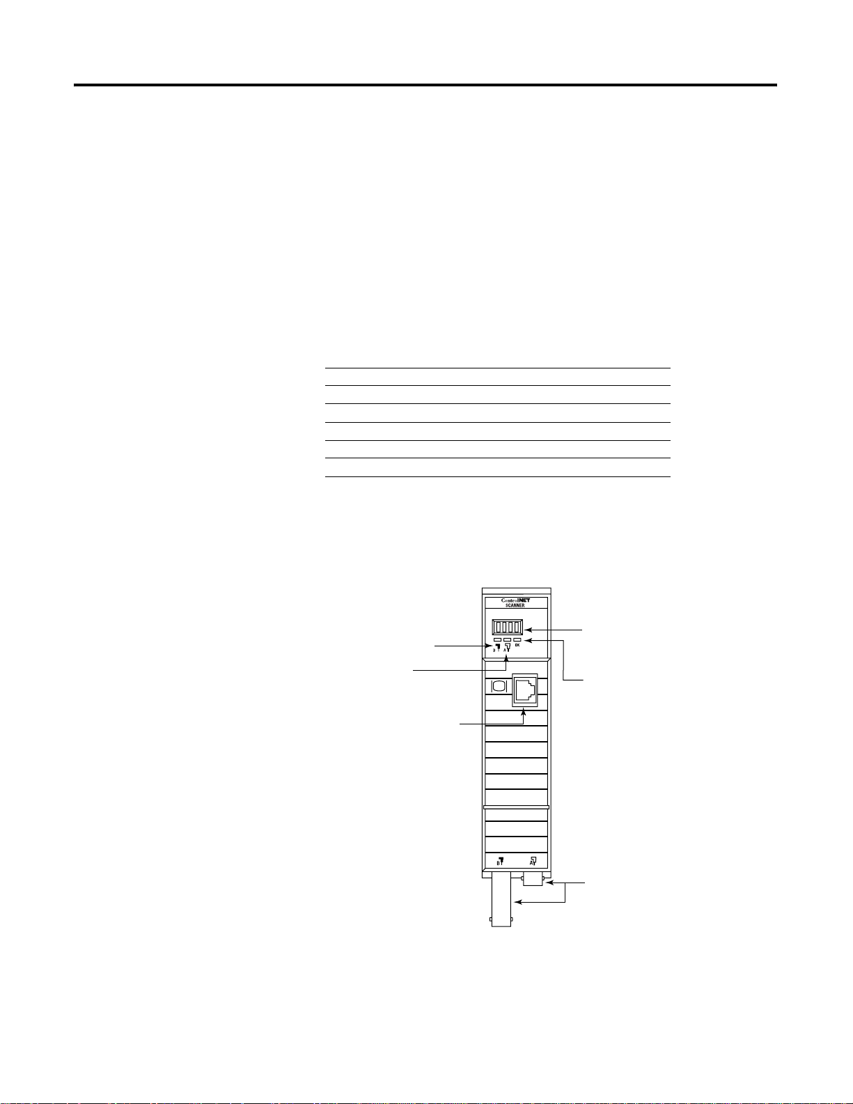
The following drawing identifies the features of the 1747-SCNR
scanner.
Module Features
For Information About See Page
Identifying scanner features 1-1
Preparing the module for installation 1-2
Selecting the ControlNet node address 1-3
Inserting the 1747-SCNR into an SLC chassis 1-4
Connecting the 1747-SCNR to a ControlNet network 1-5
SLC 500 I/O configuration 1-8
Node Address and Status Display
displays scanner node address and
Channel B
Status Indicator
Channel A
Status Indicator
ControlNet Network
Access Port
NAP RJ45 connector
status.
Module Status Indicator
indicates whether the device is
powered and is functioning properly.
ControlNet Redundant Media Ports
BNC Connectors
(Channels A and B)
1 Publication 1747-RM623D-EN-P - June 2006
30751
Page 14
1-2 Install and Connect the ControlNet Scanner
3
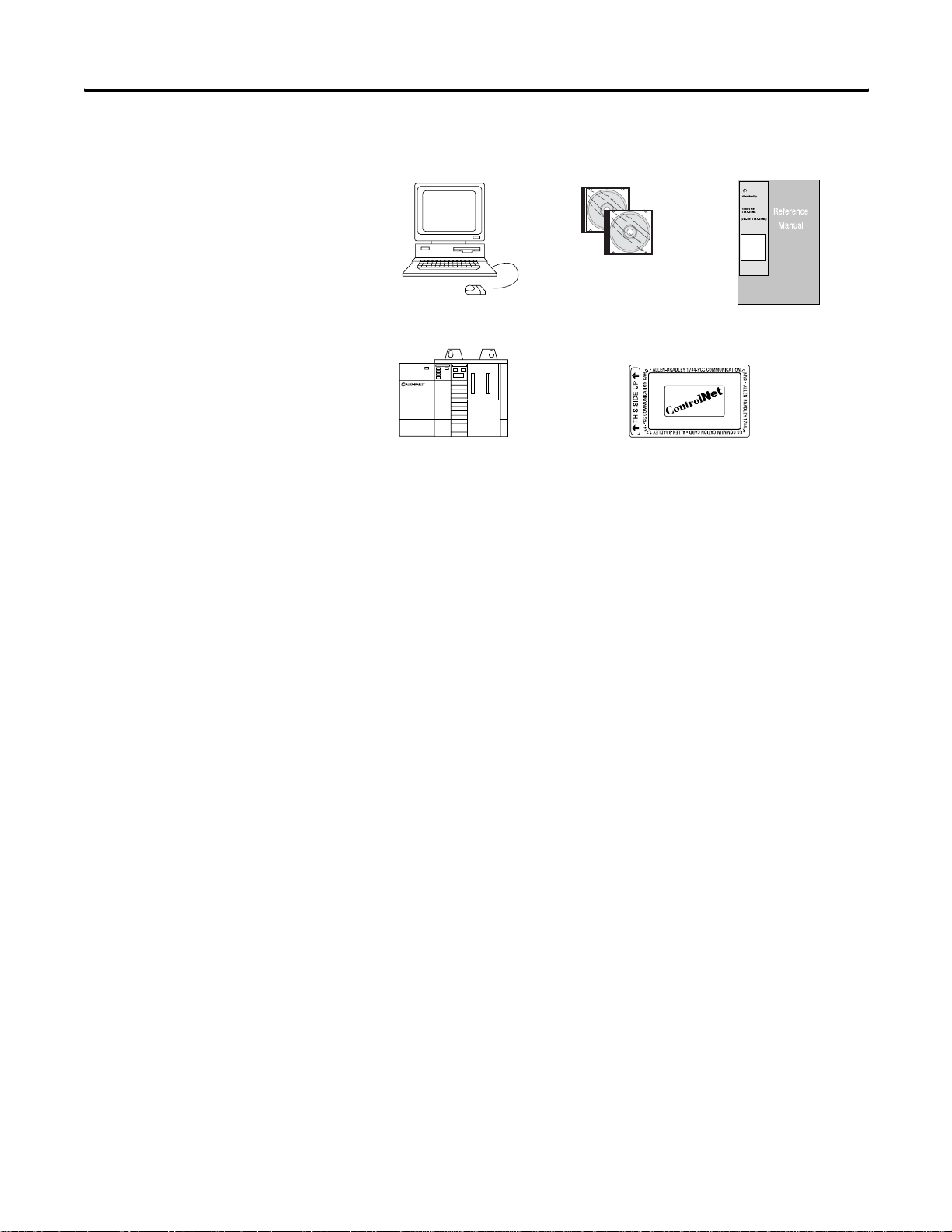
Prepare for Module Installation
Before you install your module, you need the following items:
RSNetWorx for
Personal Computer with
Microsoft Windows
SLC 1746 Chassis with SLC
5/02, 5/03, 5/04, or 5/05 Processor
and Appropriate Programming
Software (RSLogix 500 Software)
ControlNet
software,
Catalog Number
9357-CNETL3
ControlNet 1784-PCC (shown),
or 1784-PCIC, or 1784-KTCX15,
or 1770-KFC15 Module
1747-SCNR Scanner Reference
Manual, Publication 1747-RM62
(this manual)
Before you install the module, you must know how to do this.
41523
• Program and operate an Allen-Bradley SLC 50 0 programmable
controller.
• Install and configure the devices on your ControlNet network.
The 1747-SCNR scanner fits in any slot of the chassis except for the
leftmost slot of the first chassis, which is reserved for the SLC 500
processor.
Publication 1747-RM623D-EN-P - June 2006
Page 15
Install and Connect the ControlNet Scanner 1-3
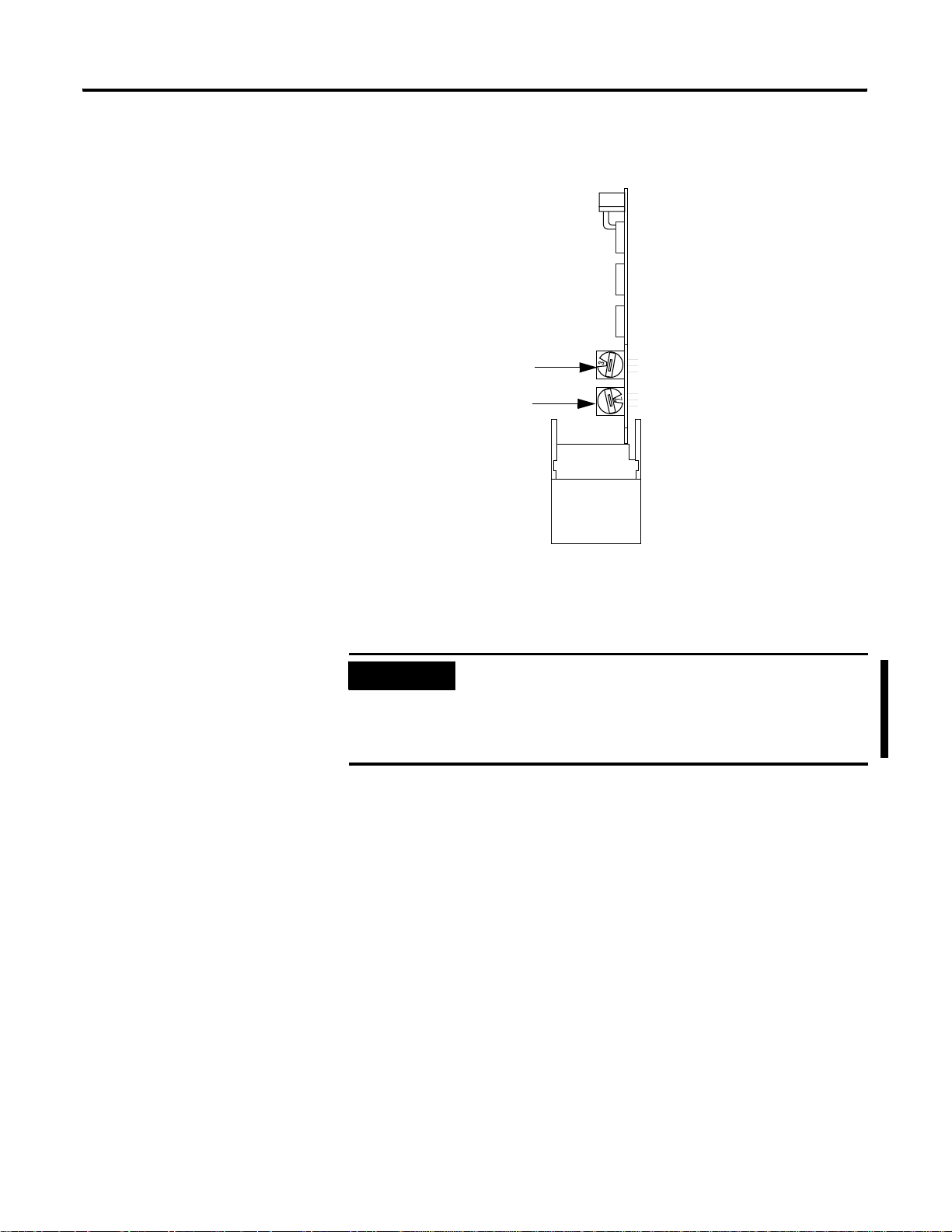
Select the ControlNet Node Address
Select the ControlNet node address of the 1747-SCNR module by
setting the two 10-digit rotary switches on the top of the scanner.
10-digit Rotary Switch: Ones Digit
10-digit Rotary Switch: Tens Digit
Top View of Module
30752
You can select a node address from 01 to 99 for a device on a
ControlNet link. Zero (00) is not a valid node address.
IMPORTANT
Since 00 is the default value from manufacturing, you
must change the node address when using the
scanner for the first time. Turning on the scanner
with the node address set to 00 clears the module
memory back to the factory default.
Publication 1747-RM623D-EN-P - June 2006
Page 16
1-4 Install and Connect the ControlNet Scanner
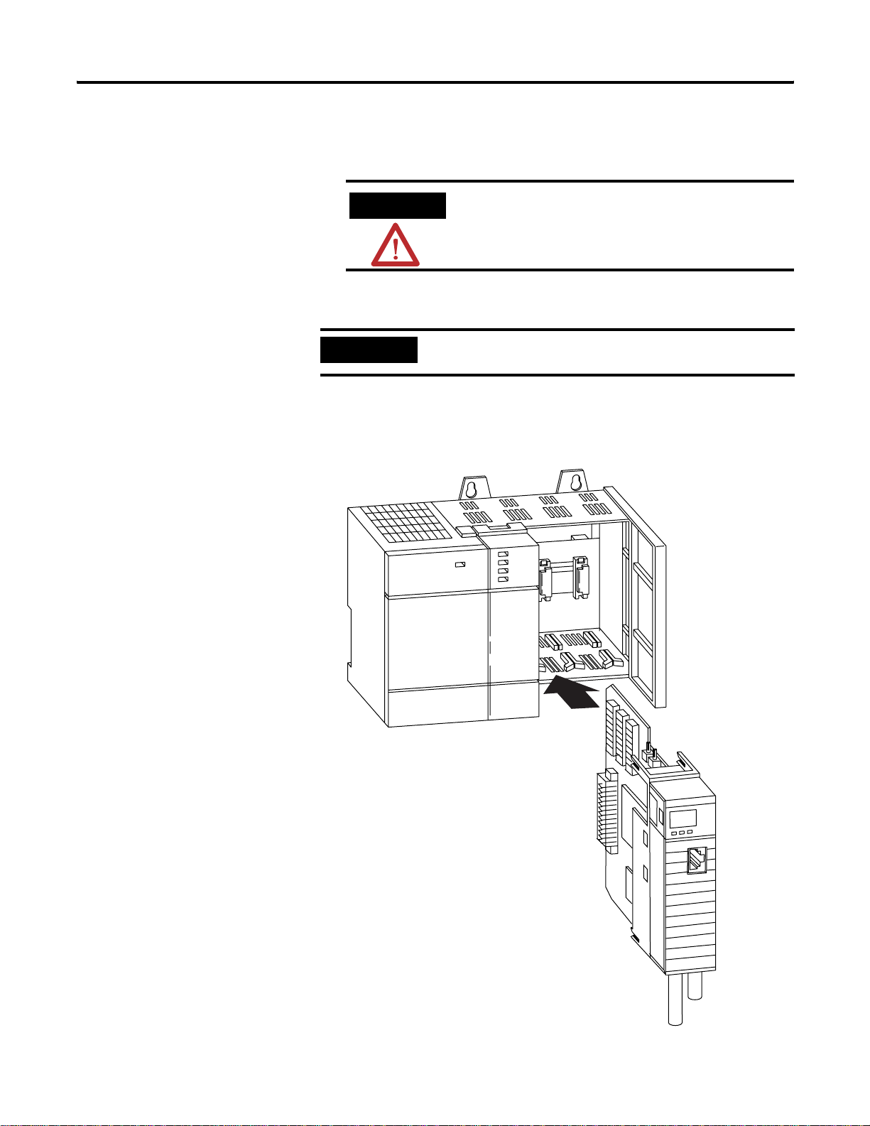
Insert the 1747-SCNR Scanner Into the Chassis
To insert the 1747-SCNR scanner into the SLC chassis complete these
procedures.
ATTENTION
Do not install the 1747-SCNR scanner with the
chassis power supply on. Installing the module
with the chassis power supply on may damage
the module.
1. Turn off the SLC chassis power supply.
IMPORTANT
If you disconnect the ac power, you lose the chassis
ground. Electrostatic damage (ESD) protection is lost.
2. Select a slot for the module in the chassis, choosing any slot
except the left-most slot of the first chassi s, which is reserv ed for
the SLC 500 processor.
Publication 1747-RM623D-EN-P - June 2006
30801-M
Page 17
Install and Connect the ControlNet Scanner 1-5
3. Insert the module into the slot you have selected, noting that we
recommend that you insert the 1747-SCNR scanner as close to
the chassis power supply as possible.
4. Apply firm and even pressure to seat the module in the I/O
chassis backplane connectors.
5. Restore power to the SLC chassis.
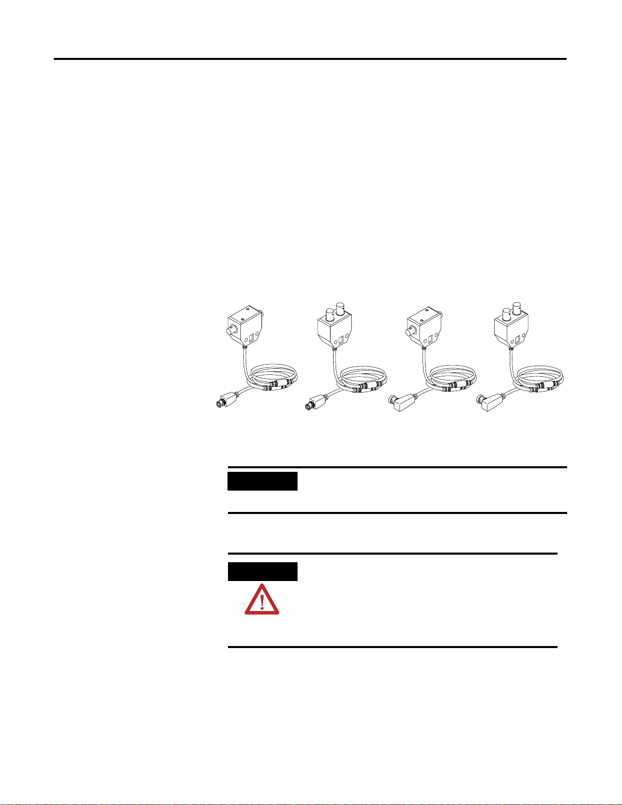
Connect to a ControlNet Network
Connect the 1747-SCNR scanner to a ControlNet network via a tap
with a 1 m (39.4 in.) drop cable. Four taps are available from
Rockwell Automation, Inc., as shown in the figure.
Straight T-tap
1786-TPS 1786-TPYR
IMPORTANT
Straight Y-tap
1786-TPYS
1786-TPR
Right-angle Y-tapRight-angle-Tap
Allen-Bradley ControlNet taps contain passive
20094
electronics and must be purchased from Rockwell
Automation for the network to function properly.
After terminating your segments, connect your node to the network.
WARNING
If you connect or disconnect the ControlNet cable
with power applied to this module or any device
on the network, an electrical arc can occur. This
could cause an explosion in hazardous location
installations. Be sure that power is removed or the
area is nonhazardous before proceeding.
Publication 1747-RM623D-EN-P - June 2006
Page 18
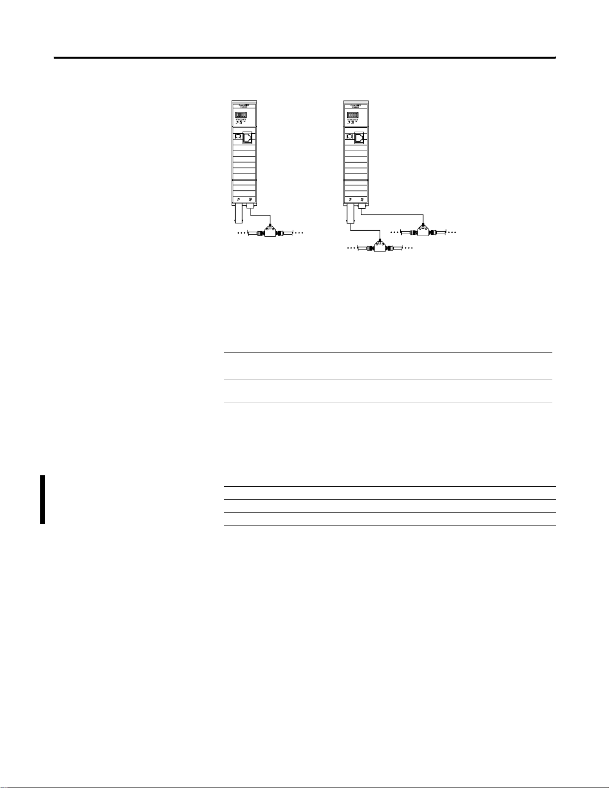
1-6 Install and Connect the ControlNet Scanner
Nonredundant Media
A
Remove the tap’s dust cap—located on the straight or right-angle connector—and set it aside.
.
Redundant Media
A
B
30802
If Your Network Supports Connect the Tap’s Straight or Right-angle
Connector
Nonredundant media To the channel A connector on the scanner—channel B is
not used.
(1)
Redundant media From the trunk-cable A to channel A on the scanner
andfrom trunk-cable B to channel B on the scanner
(1)
We recommend using channel A for nonredundant media.
For detailed information on planning and installing your ControlNet
system, see the table for a list of related publications.
Publication 1747-RM623D-EN-P - June 2006
Publication Publication Number
ControlNet Coax Tap Installation Instructions 1786-IN007
ControlNet Network Access Cable Installation Instructions 1786-TD006
Industrial Automation Wiring and Grounding Guidelines 1770-IN041
Page 19
Install and Connect the ControlNet Scanner 1-7
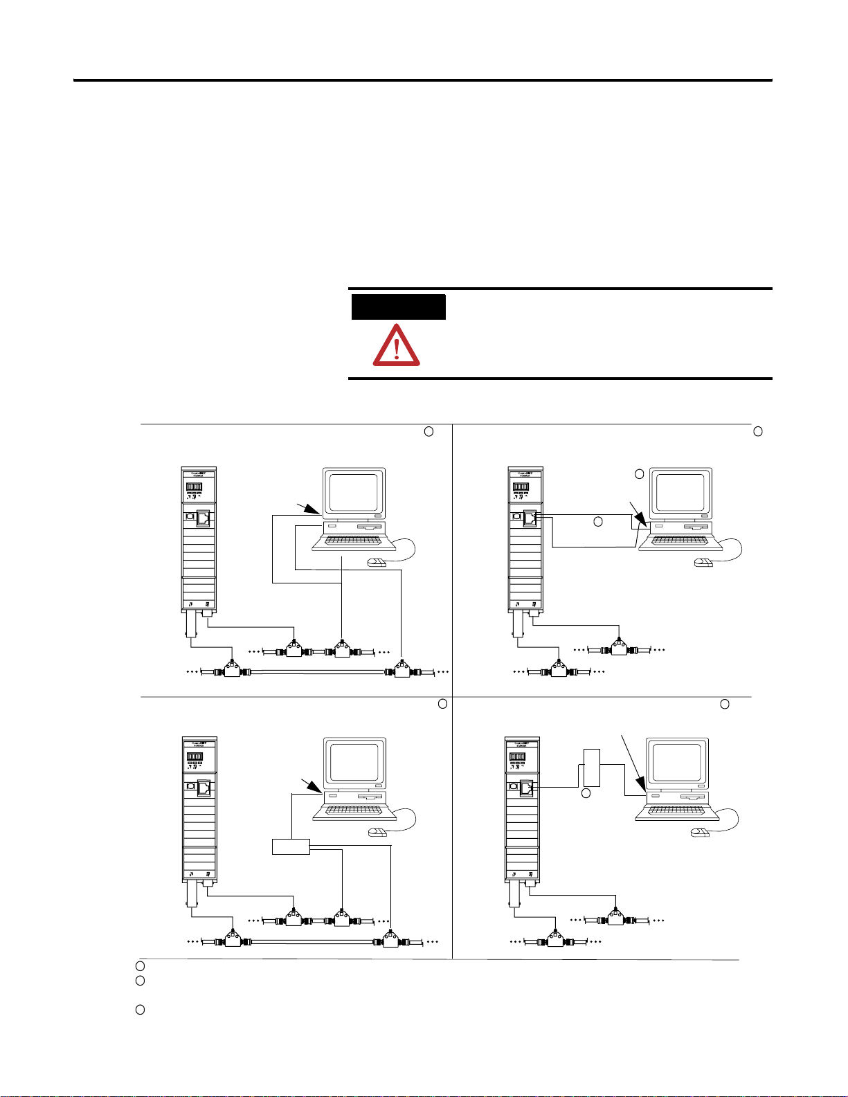
Connect Programming Terminal to a ControlNet Network
You can connect the programming terminal to a ControlNet network
through a:
• ControlNet product NAP using a network access cable
(1786-CP).
• tap on a ControlNet network.
ATTENTION
Do not connect the same communication card
to both the NAP and a tap on the ControlNet
network.
Using 1784-PCIC communication card on coax media
ControlNet 1747-SCNR Scanner
Programming Terminal
1784-KTCx15
A
B
ControlNet Network
Using 1770-KFC15 communication interface on coax media
ControlNet 1747-SCNR Scanner
Programming Terminal
Serial Connection
1
Using 1784-PCC or -PCIC communication card and NAP
ControlNet 1747-SCNR Scanner
1784-PCC
Programming Terminal
3
or -KTCx15
1786-CP
A
2
ControlNet Network
B
1
Using 1770-KFC15 communication interface and NAP
Serial Connection
1770-KFC15
1786-CP
2
1
1
1770-KFC15
A
A
B
B
ControlNet Network
1
Shown with redundant media (redundant media is not required).
2
The network access cable (1786-CP) can be plugged into any ControlNet product’s NAP to provide programming capability on the
ControlNet Network
41521
ControlNet network. A programming terminal connected through this cable is counted as a node and must have a unique address.
3
The 1784-PCC ships with its own ControlNet cable (1784-PCC1).
Publication 1747-RM623D-EN-P - June 2006
Page 20

1-8 Install and Connect the ControlNet Scanner
SLC 500 I/O Configuration for the 1747-SCNR Module
ATTENTION
Select the I/O card. If you do not have an I/O card, complete the
following procedure.
Open RSLogix 500 software and use the following procedure to
configure the 1747-SCNR module.
In the RSLogix 500 project Window:
1. Open the I/O Configuration window.
2. Select the 1747-SCNR slot number.
3. Select the 1747-SCNR module from the current available cards
list. If it is not available, perform the following steps:
a. Choose the other ..Requires I/O card type ID line in the
Current cards available list.
b. In the Other type I/O Card window, type 13628.
c. On the line associated with the scanner slot, the I/O
Configuration window will report the following:
Use the 1786-CP cable when connecting a
scanner to the network through a NAP. Using
a commercially-available RJ-style cable could
result in network failure.
Publication 1747-RM623D-EN-P - June 2006
OTHER I/O Module- ID Code = 13628
d. Double-click the scanner line to open the Advanced I/O
Configuration window.
e. Se t M0 Length to 1651 (decimal) and M1 Length to 608
(decimal).
4. Close the I/O Configuration and Advanced I/O Configuration
windows.
Page 21

Chapter
Prepare to Use the ControlNet Scanner
2
What This Chapter Contains
What Your Scanner Does
Read this chapter to understand how to use your ControlNet
1747-SCNR Scanner. The following table describes what this chapter
contains and where to find specific information.
In a typical configuration, the scanner acts as an interface between
ControlNet devices and an SLC processor. The scanner communicates
with ControlNet devices over the network to do this:
For Information About See Page
What your scanner does 2-1
Communicating with your SLC processor 2-1
Understanding ControlNet data transfer 2-3
Understanding 1747-SCNR mapping 2-5
Communicating with your devices 2-9
• Read inputs from a device.
• Write outpu ts to a device.
• Issue native ControlNet requests to a remote node on the
ControlNet link (CIP client).
• Download configuration data.
Communicating with Your SLC Processor
1 Publication 1747-RM623D-EN-P - June 2006
The scanner communicates with the processor in the form of M1/M0
File Transfers and/or Discrete I/O (DIO). Information exchanged
includes the following.
• Device I/O data
• Status and control information
• CIP client requests and response s
• Local database
An M1/M0 file transfer is a method of moving large amounts of data
between an SLC 500 processor and its scanner.
Discrete input and output (DIO) is the transfer of one to 32 words
between an SLC 500 processor and a scanner. All 32 words of input
data and all 32 words of output data are updated on each SLC
program scan.
Page 22
2-2 Prepare to Use the ControlNet Scanner
t
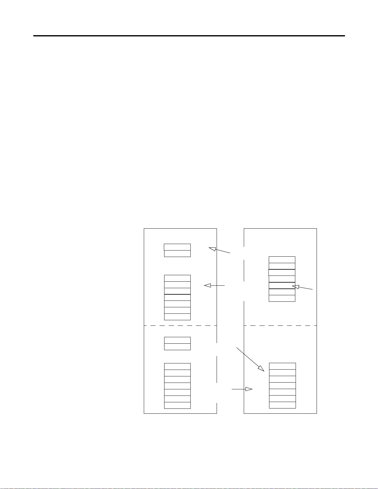
Communicating with Your SLC processor Using M1 and M0 Files
Y our processor can communicate with the scanner via M1 file transfer
reads and M0 file transfer writes.
The scanner does not send data to your processor. Data transfer
between your scanner and the processor must be initiated by the
processor. For example, data is sent, or written, to the scanner by
your processor by placing the data in the M0 file. This data is
organized in the scanner and then, based on the area you updated,
the appropriate action is initiated to send it on the ControlNet
network.
An M1 file transfer is the transfer of data from the scanner to the
processor. The scanner makes data collected from the network’s
devices available for the processor to read.
An M0 file transfer is the transfer of data from the SLC 500 processor
to the scanner. The processor writes data to the scanner’s memory.
SLC 500 Processor
Discrete Input Image
A1
B
M1 Data File
C
A2
D
E
Discrete Output Image
X
Y
M0 Data File
Z
Discrete Input
Transfer
M1 file
transfer
(read)
Discrete Output
Transfer
I/O Map
M0 file
transfer
(write)
1747-SCNR Scanner
Internal Input
Data Storage
A1
B
C
A2
D
E
ControlNe
network
Internal Output
Data Storage
X
Y
Z
Publication 1747-RM623D-EN-P - June 2006
41553
Page 23
Prepare to Use the ControlNet Scanner 2-3
S
Understand ControlNet Data transfer
The ControlNet system is designed to do this:
• Provide high-speed, repeatable, deterministic I/O transmission.
• Let control and message information co-exist on the same
physical media.
• Make sure that I/O data transfers are not affected by:
• programming-terminal activity.
• inter-scanner message activity on the network.
Scheduled Data Transfer Operations on a ControlNet Network
ControlNet scheduled data transfer on a 1747-SCNR Scanner:
• is continuous.
• transmits on the network asynchronously to the ladder logic
program scan.
• occurs at the actual rate that is determined by RSNetWorx for
ControlNet software.
For discrete I/O data transfer between logic scans (during
housekeeping), the following updates occur.
• The gathered input image is moved from the scanner to the SLC
processor's input image file for use during the next logic scan.
• The 1747-SCNR output data is updated with data from the SLC
processor output image file and is sent during the next
scheduled communication.
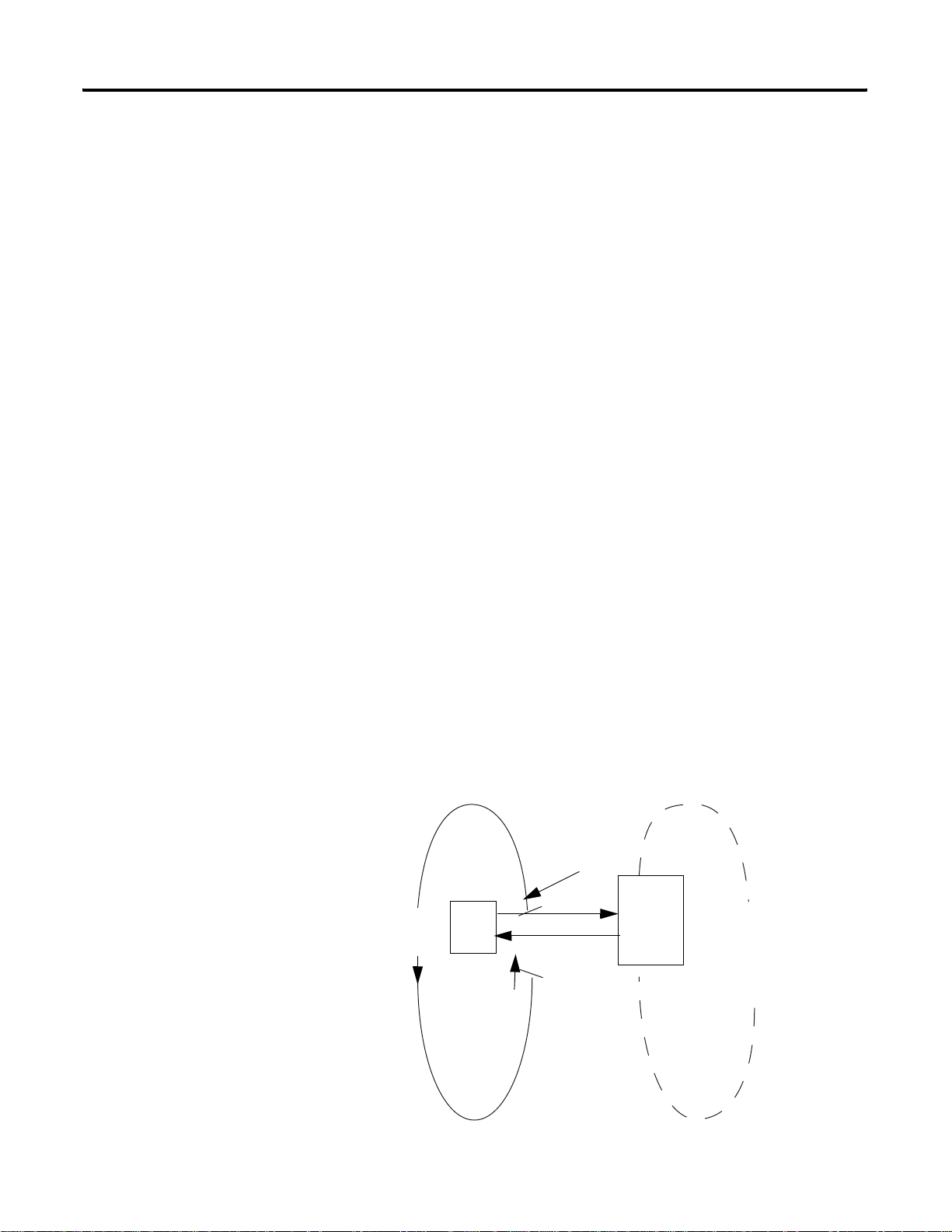
M0 and M1 files are data files that reside in the 1747-SCNR scanner
only. Data from these files will be available to the SLC processor using
ladder instructions. Scheduled data update will be triggered by the
Housekeeping period start, which occurs once per scan. This process
is illustrated below.
Housekeeping
Scheduled
Data
Table
Files
Logic Scan
LC 500 Program Scan Data Tables Files Housekeeping
Data Update
Data
Private
Memory
Buffers
Scheduled Data Transfers
41554
1747-SCNR Scheduled Data
Publication 1747-RM623D-EN-P - June 2006
Page 24

2-4 Prepare to Use the ControlNet Scanner
6
Unscheduled Data Transfer Operations on a ControlNet Network
The ControlNet network lets you use unscheduled mess agin g in
addition to deterministic delivery.
Unscheduled operations include:
• peer-to-peer messaging.
• messaging from any remote CIP client device.
• messaging from programming devices.
• CIP client message initiated by the SLC processor ladder
program.
This process is illustrated in the figure.
Housekeeping
Logic Scan
Data
Table
Files
Data
M0 file transfer
(SLC processor
read and write)
Table
Files
SLC 500 Program Scan
M0 file transfer
(write request read response)
1747-SCNR Unscheduled Data
Data Tables Files
Housekeeping
Link Layer Services
The figure illustrates link layer services.
Network Update Time (NUT)
Scheduled
Service
Unscheduled
Service
M0
Local
Database
area
M0
CIP client
message
area
Unscheduled Data Transfers
41555
Network Maintenance
Publication 1747-RM623D-EN-P - June 2006
Time
4155
Page 25

Prepare to Use the ControlNet Scanner 2-5
The ControlNet system places your scheduled transfers in the first part
of each network update interval (NUI). Time is automatically reserved
for network maintenance, and unscheduled transfers are performed
during the remainder of the interval.
Unscheduled messaging on a ControlNet network is
non-deterministic.Your application and your configuration (for
example, number of nodes, application program, NUT) deter mine
how much time there is for unscheduled messaging.
Understand 1747-SCNR Mapping
IMPORTANT
The ControlNet network reserves time for at least one
unscheduled transfer per NUI.
The 1747-SCNR scanner and the SLC processor exchange the
following information through the backplane:
• Input data
• Output data
• Status data
• Command data
• CIP messages
The 1747-SCNR mapping is described in the following. Bit field
descriptions follow each table.
Discrete Input File
Word
Offsets
0 1 N/A Module Status (see
1-31 31 Scheduled ControlNet Input
Word
Size
ControlNet
Transfer Mode
Contents Description
the next section,
“Module Status”)
Data
Bit field reporting general
status information.
You can map up to 31 words of
input data using RSNetWorx
for ControlNet software.
Publication 1747-RM623D-EN-P - June 2006
Page 26

2-6 Prepare to Use the ControlNet Scanner
Module Status (I:e.0)
Bit 0 1747-SCNR Module Faulted.
Bit 1 1747-SCNR Communication Module Fault
The 1747-SCNR scanner is not on line. See M1 word 2 (M1:e2) for the
ControlNet network status.
Bit 2 1747-SCNR Connection Fault
There is a fault in at least one scheduled connection.
Bit 3-7 Reserved.
Bit 8 Reset 1747-SCNR Module Acknowledge
The 1747-SCNR scanner will complement this bit each time the scanner is reset
due to complementing the Reset module command bit (O:e.0/8 where e is the
scanner slot number). See Example of Reset Bit Management.
Bit 9 Disable ControlNet Scheduled Connections Acknowledge
The 1747-SCNR scanner will set this bit when the Disable ControlNet
Scheduled Connections Command bit is set (O:e.0/9) and all scheduled
connections have been closed. The 1747-SCNR scanner will clear this bit when
the Disable ControlNet Scheduled Connections Command bit is cleared.
Bit 10 Scanner Mode
The 1747-SCNR scanner clears this bit when it is in idle mode. The 1747-SCNR
Scanner sets this bit when it is in run mode.
Bit 11-15 Reserved.
1747-SCNR M1 File
Word
Offsets
0 1 N/A Reserved Reserved for future use.
1 1 N/A Module
2 1 N/A ControlNet
3-255 253 Scheduled ControlNet
256-599 344 N/A Reserved Reserved.
600-607 8 N/A Connection
Word
Size
ControlNet
Transfer Mode
Contents Description
Value indicating the current
Status (See
the next page
“Module
Status”)
Status (See
the next page
“ControlNet
Status”)
Input Data
Status
operational status of the module. See
the Troubleshooting for probable
causes and recommended actions.
Value indicating the current channel
LEDs.
You can map scheduled input data in
this area using RSNetWorx for
ControlNet software.
Bit field reporting scheduled
connections status.
Two consecutive bits per scheduled
connection:
Connection State
(Even bit numbers)
1:connection opened
0:connection closed
Remote Device Mode
(Odd bit numbers)
1:remote device is in run mode
0:remote device is in idle mode
Publication 1747-RM623D-EN-P - June 2006
Page 27

Prepare to Use the ControlNet Scanner 2-7
Module Status (M1:e.1)
See Troubleshooting for probable causes and recommended actions.
Value Description
0x20 The scanner is not configured.
0x21 The current configuration is not valid.
0x22 Connections are configured, but no connections are established.
0x23 Connections are configured, but only 25% are successfully established.
0x24 Connections are configured, but only 50% are successfully established.
0x25 Connections are configured, but only 75% are successfully established.
0x26 All configured connections are established.
0x42 The node address is set to 00. This caused the scanner to erase network and
connection configuration stored in flash.
0x43 The scanner detected a network error due to a ControlNet cable problem or there
are no other nodes on the network.
0x44 The scanner has the same ControlNet address as another device on the network.
ControlNet Status (M1:e.2)
See the table that contains bit numbers and their descriptions.
Bit 0-2 Channel A status
Value LED State
000 Off
001 Green
010 Flashing green/off
011 Flashing red/off
100 Flashing red/green
101 Alternating red/off
110 Alternating red/green
111 Red
Bit 3 Reserved
Bit 4-6 Channel B status
Value LED State
000 Off
001 Green
010 Flashing green/off
011 Flashing red/off
100 Flashing red/green
101 Alternating red/off
110 Alternating red/green
111 Red
Bit 7-15 Reserved
Publication 1747-RM623D-EN-P - June 2006
Page 28

2-8 Prepare to Use the ControlNet Scanner
Discrete Output File
Word
Offsets
0 1 N/A Module Command Bit field used to send commands
1-31 31 Scheduled ControlNet Output
Word
Size
ControlNet
Transfer
Mode
Contents Description
to the 1747-SCNR Scanner.
You can map up to 31 words of
Data
output data using RSNetWorx for
ControlNet software.
Module Command (O:e.0)
Bit 0-7 Reserved
Bit 8 Reset Scanner Command
By complementing this bit, you reset the 1747-SCNR scanner (the reset occurs
when the SLC slot is de-activated).
It is important to note that if you do not disable the slot while the scanner is
resetting, the SLC module will fault with the error code nn57h (specifically, I/O
module in slot nn did not respond to a lock shared memory command in the
requested time limit) where nn is the slot number of the scanner . This is why the
reset bit change is not taken into account until the slot is disabled.
Bit 9 Disable ControlNet Scheduled Connections Command
When the bit value is 1, the 1747-SCNR scanner will close all scheduled
connections.
When the bit value is 0, the 1747-SCNR scanner will enable all scheduled
connections.
Bit 10 Scanner Mode Command
When the bit value is 0, the 1747-SCNR scanner is forced to Idle mode.
When the bit value is 1, the scanner’s mode will be determined by the mode of
the processor in slot 0.
Bit 11-15 Reserved
Publication 1747-RM623D-EN-P - June 2006
Page 29

1747-SCNR M0 File
Prepare to Use the ControlNet Scanner 2-9
Word
Offsets
0-2 3 N/A Reserved Reserved.
3-255 253 Scheduled ControlNet
256-699 444 N/A Reserved Reserved.
700-955 256 Unscheduled Local
1000-1650 651 Unscheduled CIP Client
Word
Size
ControlNet
Transfer Mode
Contents Description
Using the RSNetWorx for
Output Data
Database
Message
Area
ControlNet software, you can map
scheduled output data in this area.
Memory area used by remote
devices to read or write data using
CIP messaging or PLC-5 messaging.
Memory used to send CIP client
requests. These messages are then
sent by the 1747-SCNR module as
unscheduled messaging.
Only Input and Output data (from Input file, Output file, M0
ControlNet Output data area, and M1 ControlNet Input data area) are
exchanged during scheduled time.
Data transfer to the M0 Local Database is performed using
Unscheduled messaging. Services available to read or write in this
area are Set Attribute Single, Get Attribute Single, Set Member, and Get
Member.
Communicating with Your Devices
The 1747-SCNR scanner supports up to 64 simultaneous scheduled
connections and up to 50 simultaneous unscheduled connections. The
1747-SCNR scanner also supports up to 32 simultaneous incoming
unconnected requests.
I/O Scheduled Data Transfer
Data received from the devices, or input data, is organized by the
scanner and made available to your processor in the Input file or the
M1 ControlNet data area.
Data received from your SLC processor, or output data, is stored
within the Output file or M0 ControlNet data area. The 1747-SCNR
scanner can then send the data to your remote ControlNet devices.
Publication 1747-RM623D-EN-P - June 2006
Page 30

2-10 Prepare to Use the ControlNet Scanner
All scheduled data transfer to Input, Output, M0 and M1 files must be
mapped on a ControlNet network. You have to specify where I/O
data is to be read from or written to, in other words, mapped. Data
size and location within 1747-SCNR data files have to be configure d
for each connection you want to setup with a remote device. The
configuration is performed using RSNetWorx for ControlNet so ftware.
Unscheduled Data Server
The scanner supports some CIP data server functionality on a specific
local database of 256 words located in the M0 file. Any device on
ControlNet can read or write in this database using the supported
services as described in Local Database Access Using PLC-5 MSG
Instructions and Local Database and ControlNet Data Files Access
Using CIP Messaging.
The SLC processor that has read and write access to this area is then
able to receive or modify data into the database.
Using this Local Database:
• a device can send data to an SLC processor us in g unscheduled
data transfer.
• two devices can exchange unscheduled data by using this
database as a proxy data storage.
• a PLC-5 controller can exchange data with the SLC processor by
reading or writing in this area using MSG instructions.
• an HMI can exchange data with the SLC processor by reading or
writing in this area using PLC-5 type read and write commands.
Publication 1747-RM623D-EN-P - June 2006
Page 31

Prepare to Use the ControlNet Scanner 2-11
CIP Client Request Transfer
The scanner provides some limited CIP client messaging capability.
Using ladder programming, you can manually build a message request
for up to approximately 240 words of in and approximatel y 240 words
of out data, to let configuration and other limited messaging to remote
devices.
The CIP client message management is detailed in CIP Client
Management.
SLC 5/03, 5/04, and 5/05 processors at OS firmware level, series C,
FRN 10, or later, include ControlNet explicit message (CEM)
instruction capability. The CEM instruction uses the CIP client message
capability of the scanner. See Work with the ControlNet Explicit
Message Instruction section for de tails.
Publication 1747-RM623D-EN-P - June 2006
Page 32

2-12 Prepare to Use the ControlNet Scanner
Notes:
Publication 1747-RM623D-EN-P - June 2006
Page 33

Chapter
3
Configure and Map Scheduled Data Exchange with RSNetWorx for ControlNet Software
What This Chapter Contains
Begin the Configuration
This chapter provides information about the mapping of scheduled
connections between 1747-SCNR remote devices. This chapter also
contains questions you should ask before configuring your 1747-SCNR
scanner. The following table describes what this chapter contains and
its location.
For Information About See Page
Beginning the configuration process 3-1
Questions to ask 3-1
Data transfer mapping 3-2
Planning before configuring your scanner helps make sure you can:
Process
• use your memory bandwidth efficiently.
• give attention to device-specific needs and requirements.
• give priority to critical I/O transfers.
• leave room for expansion.
Questions to Ask
1 Publication 1747-RM623D-EN-P - June 2006
Here are some questions you should ask yourself before you begin
configuring the 1747-SCNR scanner:
• What is on your network?
This is a very important question to answer. You should be
familiar with each device's:
• communication requirements.
• I/O importance and size.
• frequency of message delivery.
• How might this network appear in the future?
At this point in your planning, it is advantageous for you to have
some idea of how the network could be expanded. When
mapping your I/O, you have the opportunity to leave room for
future I/O. Answering this question now can save time and
effort in the future.
Page 34

3-2 Configure and Map Scheduled Data Exchange with RSNetWorx for ControlNet Software
Data Transfer Mapping
You can us e the configuration software (RSNetWorx for ControlNet
software) to select either Input or M1 files for input data and either
Output or M0 files for output data. However, it is more appropriate to
use Input and Output files for critical I/O data transfer and M1 and M0
for non-critical I/O data transfer.
Input and Output files contain 31 words each. These files are
appropriate for discrete data. If you have more than 31 words to
transfer, you have to map the remaining connections in M1 and M0
ControlNet data areas.
For input data, you can map your connections anywhere in Input and
M1 ControlNet data areas. It is not possible to overlap the mapping of
two independent input connections.
For output data, you can map your connections anywhere in Output
and M1 ControlNet data areas (refer to chapter 2 for exact memory
mapping.) The overlapping of two output connections is authorized.
IMPORTANT
It is your responsibility to check that no unexpected
overlapping has been configured.
Data exchanged through a single connection cannot be split between
two distinct locations. This means that a 5 word connection cannot
start at location I:29 and continue at another location in the M1 file.
Likewise, you cannot configure this connection with two first words at
address M1:e.4 and M1:e.5 and the rest between M1:10 and M1:12.
You access ControlNet data located in M1 and M0 files using the COP
(copy) instruction in your ladder program. Since the maximum data
length you can transfer with the COP instruction is 128 words, you
need two instructions to copy the whole ControlNet area and control
and status word in processor memory. If you have less than 128
words of data mapped in an M file, we recommend that you pack
them together so that you can use a single copy instruction.
IMPORTANT
When you are building your mapping, we recommend that you save
free space between device connections if the size of these
connections may increase in the future.
To ensure data consistency at the connection level,
be sure that, for all connections configured, data of a
same connection are copied into processor memory
using a single copy instruction.
Publication 1747-RM623D-EN-P - June 2006
Page 35

Chapter
4
Work with the ControlNet Explicit Message Instruction
What This Chapter Contains
Understand the ControlNet Explicit Message (CEM) Instruction
The following table describes what this chapter contains.
The CEM instruction lets generic Common Industrial Protocol (CIP)
commands be initiated to devices, such as drives, communicating on
ControlNet networks. This instruction requires RSLogix 500 software,
version 7.10 or later, for programming.
The CEM instruction uses the explicit message capability built into the
1747-SCNR ControlNet scanner.
While not adding any additional capability over what already exists in
the scanner, the CEM instruction simplifies the programming,
configuration, monitoring, and troubleshooting of explicit messages
on the ControlNet network.
For Information About See Page
ControlNet Explicit Message (CEM) Instruction Overview 4-1
How to Work with the Explicit Message Instruction 4-2
How to Work with the CEM Instruction Parameters 4-2
How to Work with the CEM Instruction Setup Screen Paramter 4-3
Unlike I/O configured in the scanner’s scan list, which is updated on a
continual basis, explicit messages let data be sent and received on an
as-needed basis, minimizing network traffic. For in stan ce, you may
want to write configuration parameters to a drive once at machine
start-up time.
The CEM instruction can be used with any SLC 5/03, 5/04, or 5/05
processor that is at OS firmware level Series C, FRN 10, or later.
1 Publication 1747-RM623D-EN-P - June 2006
Page 36

4-2 Work with the ControlNet Explicit Message Instruction
The CEM instruction uses an integer control block for storing the
instruction parameters and a configuration setup screen, similar to the
MSG instruction. The CIP commands consist of a Service Code; the
object Class, Instance, and Attribute; and Send and Receive Data (if
required for the selected Service Code). The setu p screen provides a
list of standard CIP Services to select from, including:
• Read Assembly.
• Write Assembly.
• Read Parameter.
• Write Parameter.
• Generic Get Attribute Single.
• Generic Set Attribute Single.
In addition, a Custom setting lets you enter any Service Code. Send
data and receive data are stored in separate data table files.
Work with ControlNet Explicit Message (CEM)
Fixed SLC
SLC
5/01
5/02
Output Instruction
SLC
SLC
SLC
5/03
5/04
5/05
•••
This is an output instruction that lets you initiate unconnected CIP
Generic messages via a 1747-SCNR ControlNet scanner installed in the
local chassis.
These messages can be initiated to any nodes on the same ControlNet
network as the 1747-SCNR module, regardless of whe ther the
destination node is in the scanner’s scan list or not, and regardless of
whether the scanner is in Run mode or Idle mode.
Each scanner can process only one CEM instruction at a time. The
instruction is similar in operation to a standar d MSG instruction.
Publication 1747-RM623D-EN-P - June 2006
Page 37

Work with the ControlNet Explicit Message Instruction 4-3
CEM Instruction Parameters
Enter the following parameters when programming this instruction.
• Control Block is an integer file address that you select. It is a
block of words, containing the status bits and other data
associated with the CEM instruction.
• Control Block Length is a display-only field that indicates how
many integer file words are being used by the control block. For
the CEM instruction, the length is always 67 words.
CEM Instruction Setup Screen Parameters
Read these sections for information about the parameters for the CEM
instruction setup screens.
Parameters for this controller on the general tab include the following.
• 1747-SCNR Slot
This drop-down field lists all of the local slots that contain
ControlNet scanner (1747-SCNR) modules within the IO
Configuration. Select the slot number of the particular scanner
that this explicit message will be initiate d through.
• Size in Words (Receive Data)
This field defines the size of the integer data file that will be
used to store the data that is returned by this explicit message
command. For best performance, define this file size to only be
as large as is required. If no receive data is expected, you may
leave this field at 0 and no receive data file will be defined. If
unsure of how much data will be returned, you may select up to
the maximum size of 250 words, and then reduce the size later
based on experience.
• Size in Words (Send Data)
This field defines the size of the integer data file that will be
used to store the data that is sent along with this explicit
message command. For best performance, define this file size to
only be as large as is required. If no send data is required, you
may leave this field at 0 and no send data file will be define d. If
unsure of how much data will be sent, you may select up to the
maximum size of 248 words when defining the instruction, and
then reduce the size later based on experience.
Publication 1747-RM623D-EN-P - June 2006
Page 38

4-4 Work with the ControlNet Explicit Message Instruction
• Data Table Address (Send Data)
• Data Table Address (Receive Data)
If Size in Words (Receive Da ta) is non-zero, then this field requires a
starting integer (N) file address for storing the Receive Data.
Parameters for target device on the general tab include the following.
• Message Timeout (x1 ms)
• ControlNet Addr (dec)
If Size in Words (Send Data) is non-zero, then this field requires
a starting integer (N) file address for storing the Send Data.
The amount of time in milliseconds that the scanner will wait for
a reply to the explicit message command. Range is 2 to 32767.
The target ControlNet node address. Valid range is 1 to 99. If
you enter in the local scanner’s ControlNet node add ress, the
command is executed by the local scanner .
• Service
This pull-down menu lets you select services based on name
rather than Service Code. The Custom service lets you enter any
Service Code in the hexadecimal range of 1 to 7F. These services
are listed in the pull-down selection.
– Read Assembly
– Write Assembly
– Write Output Point
– Read Output Point
– Read Input Point
– Read Parameter
– Write Parameter.
– Read Analog Input
– Write Analog Output
– Generic Get Attribute Single
– Generic Set Attribute Single
– Generic Get Member
– Generic Set Member
– Reset Identity Object
– Custom
Publication 1747-RM623D-EN-P - June 2006
Page 39

Work with the ControlNet Explicit Message Instruction 4-5
• Service Code (hex)
This field is read-only unless the Custom Service is selected.
Possible Service Codes are 1 to 7F (hex). See Volume 1 of the
CIP Common Specification, Appendix A, for the list of valid
explicit messaging Service Codes.
• Class (hex)/(dec)
Possible Classes are 0 to FF (hex). See Volume 1 of the CIP
Common Specification for the list of defined Classes. Yo u may
either enter in a hexadecimal Class value in the (hex) field or a
decimal Class value in the (dec) field.
• Instance (hex)/(dec)
Possible Instances are 0 to FFFF (hex). See Volume 1 of the CIP
Common Specification for the list of valid Instances for each
Class. You may either enter in a hexadecimal Instance value in
the (hex) field or a decimal Instance value in the (dec) field.
• Attribute (hex)/(dec)
Possible Attributes are 0 to FFFF (hex). See Volume 1 of the CIP
Common Specification for the list of valid Attributes for each
Class. You may either enter in a hexadecimal Attribute value in
the (hex) field or a decimal Attribute value in the (dec) field.
• Member (hex)/(dec)
Possible Members are 0 to FFFF (hex). See Volume 1 of the CIP
Common Specification for the list of valid Members for each
Class. You may either enter in a hexadecimal Member value in
the (hex) field or a decimal Member value in the (dec) field.
Publication 1747-RM623D-EN-P - June 2006
Page 40

4-6 Work with the ControlNet Explicit Message Instruction
Definitions for Message Status Bits on the General Tab
See the table that lists the various status bits associated with the CEM
instruction as displayed in the CEM instr uction setup screen.
CEM Instruction Setup Screen Status Bit
Bit Definition Bit Mnemonic Bit Address
Timeout TO 08
Error ER 12
Done DN 13
Enabled EN 15
Waiting for slot WS 10
• Timeout bit TO (word 0, bit 8) is set when the scanner times out
• Error bit ER (word 0, bit 12) is set when the message has failed
• Done bit DN (word 0, bit 13) is set when the message has
• Enabled bit EN (word 0, bit 15) is set after the message rung
• Waitin g for Slot bi t WS (word 0 , bit 10) is set when the message
the message either due to no response from the target device or
due to no reply being returned within the configured timeout
period. The ER bit will be set at the same time the TO bit is set.
This bit is reset the next time the message rung goes from false
to true. Do not set or reset this bit. It is informational only.
to complete successfully. This bit is reset the next time the
message rung goes from false to true. Do not set or reset this bit.
It is informational only.
completed successfully. This bit is reset the next time the
message rung goes from false to true. Do not set or reset this bit.
It is informational only.
goes from false to true and the scanner accepts this message
because it is not currently processing any other explicit
messages. (The scanner can process only one CEM instruction at
a time.) If the message rung goes false before the scanner
accepts this message, then the enable bit will remain off and the
message will not be executed. This bit is reset when the
message has completed with either the Done bit set or the error
bit set and the message rung goes false. If the message rung
conditions remain true, you may retrigger the message
instruction by resetting this bit after either the ER or DN bit has
been set, indicating that the previous execution has completed.
rung goes from false to true, but the scanner is still processing
another CEM instruction. To ensure that this message gets
processed, you must leave the message rung conditions true
until the WS bit is reset and the EN bit is set, indicating that the
scanner has accepted this message for processing. Do not set or
reset this bit. It is informational only.
Publication 1747-RM623D-EN-P - June 2006
Page 41

Work with the ControlNet Explicit Message Instruction 4-7
Scanner Status, Error, and Error Description on the General Tab
The Scanner Code displays the explicit message status returned by the
scanner. A scanner code of 0 means no errors. See the CEM
Instruction Scanner Codes table for a list of other valid scanner codes.
CEM Instruction Scanner Codes
Scanner Code Description of Scanner Status
201H Invalid command data size
202H Internal fault detected
204H Invalid service code
205H Invalid IOI size
206H Invalid CIP request block contents
207H CIP message request timeout
208H CIP timeout value too small
Publication 1747-RM623D-EN-P - June 2006
Page 42

4-8 Work with the ControlNet Explicit Message Instruction
A scanner code of 0x207 results in an error code of 1. All other
scanner codes listed result in an error code of 2. The Valid CEM
Instruction error codes table lists all valid CEM instruction error codes.
Valid CEM Instruction Error Codes
Error Code Description of Error Condition
0 No error.
1 Timeout error. ControlNet explicit message timed out by scanner.
2 Scanner error. See Scanner Status.
3 Configuration error. Send file length > 248 or invalid IOI size.
5 Processor error. Invalid response.
6 Processor error. Unsolicited response received.
7 Configuration error. Size of response data > receive data size.
For error code 4, the error de scription displays the CIP response error
code and description as documented in the CIP Common
Specification, Appendix B.
Any time the Error code is non-zero, th e CEM error (ER) bit is set.
Publication 1747-RM623D-EN-P - June 2006
Page 43

Work with the ControlNet Explicit Message Instruction 4-9
Send Data Tab
The Send Data Tab provides a convenient way of viewing and
entering in data to be sent along with the explicit message command.
The data is shown in byte format with a selectable radix of either
Decimal or Hex/BCD. The display only shows the number of words
that are defined in the Size in Words (Send Data) field, starting with
the low byte of the first word as defined in the Data Table Address
(Send Data) field. If the Size in Words is zero, then no data is
displayed. You can also change the data being viewed, but on ly when
offline or during an online edit. Click on the data and enter in a byte
value based on the current radix (0 to 255 for Decimal and 0 to FF for
Hex/BCD). The changed data gets copied to the Send Data data table
file when the rung is accepted. To upda te the Send Data display with
the current values stored in the Send Data data table file, click on the
Refresh button.
Receive Data Tab
The Receive Data Tab provides a con veni ent wa y of vie wing th e data
that is returned by the target device in response to the explicit
message command sent. The data is shown in byte format with a
selectable radix of either Decimal or Hex/BCD. The display only
shows the number of words that are defined in the Size in Words
(Receive Data) field, starting with the low byte of the first word as
defined in the Data Table Address (Receive Data) field. If the Size in
Words is zero, then no data is displayed. To update the Receive Data
display with the current values stored in the Receive Data data table
file, click on the Refresh button.
Publication 1747-RM623D-EN-P - June 2006
Page 44

4-10 Work with the ControlNet Explicit Message Instruction
Control Block Layout
See this table for the control block layout.
SLC 5/0x ControlNet Explicit Message (CEM) Control Block Structu re
15 14 13 12 11 10 09 08 07 06 05 04 03 02 01 0
Word 0 EN DN ER WS TO Reserved by the 1747-SCNR module
Word 1 Target MAC ID
Word 2 Message Timeout Preset (x1 ms)
Word 3 Complex I0I Size
Word 4 Reserved Service Code
Word 5 Reserved Class
Word 6 Instance
Word 7 Attribute
Word 8 Member
Word 9 Size of Command Data (Words)
Word 10 Request Status - Scanner Status (Scanner Code)
Word 11 Response Status
Word 12 Extended Status Size (Words)
Word 13 Size of response and status (Words)
Word 14 Complex IOI Buffer
- - - - - - Word 63
Word 64 Error Code Transaction ID
Word 65 Extended Status Debug Word 1
Word 66 Extended Status Debug Word 2
(Lets you to manually set IOI)
Publication 1747-RM623D-EN-P - June 2006
Page 45

Troubleshoot
M
Chapter
5
What This Chapter Contains
Troubleshoot with the
The following table describes what this chapter contains and its
location.
The 1747-SCNR module has indicators on the front plate, as shown in
the figure.
Status Indicators and
Status Display
For Information About See Page
Troubleshooting 4-1
Apply chassis power 4-2
Alphanumeric display 4-2
OK indicator and display mnemonics 4-3
Status Display and
Node Address
OK indicator
ControlNet
Status Indicators
30750-
These indicators are the following.
• An alphanumeric display (of status and node address)
• A and B status indicators
• OK
Use these indicators to troubleshoot the scanner.
1 Publication 1747-RM623D-EN-P - June 2006
Page 46

5-2 Troubleshoot
Apply Chassis Power
Alphanumeric Display
When you apply chassis power , the module addre ss and status display
cycles through the following mnemonics:
1. POST - The 1747-SCNR runs Power On Self Test.
2. 1111, 2222, etc. - The 1747-SCNR is executing its startup
sequence.
3. The 1747-SCNR firmware version is displayed temporarily after
startup.
4. A#nn (where nn = ControlNet node address) then I/O or I/OX
(based on the number of connections configured and
established) then IDLE or RUN (based on the scanner mode).
The four character alphanumeric display provides you with additional
visual information about the current operational status of the module.
See the tables that describe problems that may occur while using your
1747-SCNR module, the probable causes, and the recommended
action.
Publication 1747-RM623D-EN-P - June 2006
Page 47

T roubleshoot 5-3
OK Indicator and Display
The OK indicator is handled consistently with the Con t ro lNet
specifications for the Identity object.
Mnemonics
Sequence OK
Indicator
Startup Alternating
red/green
Run time Green A#XX N/A ControlNet node
Alpanumeric
Display
POST N/A The 1747-SCNR module
FIRM
WARE
I/O
IDLE N/A The scanner is in idle
RUN N/A The scanner is in run
EDIT N/A The scanlist in the
Module Status
Word (M1 file)
N/A 1747-SCNR firmware
0x26 All configured
Description Probable Cause Recommended Action
is running Power On Self
Test.
revision. This is a
temporary display after
start up.
address
connections are
established.
mode.
mode.
1747-SCNR is being
modified.
Power was applied to
the module.
Power was applied to
the module.
None No action required.
None No action required.
The SLC processor in
slot 0 is in program
mode or the Scanner
Mode Command bit of
the Module Command
word is clear (O:e.0/
10 where e is the
scanner slot number).
The SLC processor in
slot 0 is in run mode
and the Scanner
Mode Command bit of
the Module Command
word is set (O:e.0/10).
Edits have been
enabled with
RSNetWorx for
ControlNet software.
Note that previously
configured
connections will be
reestablished if lost.
Newly configured or
changed connections
will not be
established until edits
are accepted.
No action required.
No action required.
If you want to put the
scanner into run mode,
put the SLC processor in
slot 0 into run mode and
set the Scanner Mode
Command bit of the
Module Command word
(O:e.0/10) using an
unconditional OTE
instruction.
If you want to put the
scanner into program
mode, either put the SLC
processor in slot 0 into
program mode or clear
the Scanner Mode
Command bit of the
Module Command word
(O:e.0/10).
Finish modifying the
scanlist with RSNetWorx
for ControlNet software
and then accept edits.
Cancel edits with
RSNetWorx for
ControlNet software.
Publication 1747-RM623D-EN-P - June 2006
Page 48

5-4 Troubleshoot
Sequence OK
Indicator
Run time Flashing
Green
Alpanumeric
Display
I/OX
Module Status
Description Probable Cause Recommended Action
Word (M1 file)
0x20 The scanner is not
configured.
0x21 The current
configuration is not
valid.
The scanner is not able
to start any scheduled
communication to
remote devices. Only
unscheduled
communication is
possible.
I/O
0x22
Connections are
configured but no
connections are
established.
I/O
0x23
Connections are
configured but only 25%
are successfully
established.
I/O
I/O
0x24
0x25
50%
75%
EDIT N/A The scanlist in the
1747-SCNR module is
being modified.
Module is not
configured.
Module is not
configured properly.
View the Connection
Status screen in
RSNetWorx for
ControlNet software
to see why the
connections are not
established.
Module bandwidth is
exceeded.
Edits have been
enabled with
RSNetWorx for
ControlNet software.
Note that previously
configured
connections will be
reestablished if lost.
Newly configured or
changed connections
will not be
established until edits
are accepted.
Use RSNetWorx for
ControlNet software to
download a new
configuration.
Use RSNetWorx for
ControlNet software to
schedule the existing
configuration.
Use RSNetWorx for
ControlNet software to
download a new
configuration.
Check to see if the
1747-SCNR and the
remote devices are
correctly connected to
the ControlNet network.
Reduce the number of
scheduled connections
by:
- using a discrete rack
connection instead of
multiple discrete module
connections
- combining multiple I/O
racks into a single I/O
rack
- combining multiple
peer-to-peer messages
into one message.
Increase your Network
Update Time and/or
increase the Requested
Packet Intervals for
scheduled data transfers.
Increase your SLC 500
ladder program scan by
adding more logic.
Finish modifying the
scanlist with RSNetWorx
for ControlNet software
and then accept edits.
Cancel edits with
RSNetWorx for
ControlNet software
Publication 1747-RM623D-EN-P - June 2006
Page 49

T roubleshoot 5-5
Sequence OK
Indicator
Run time Flashing
Green
Errors Off None N/A Module is not
Flashing
Green
Red (Scrolling
Flashing
Red
Alpanumeric
Display
SIGM N/A A scanner signature
N/A 0x43 Network error. Cable error or no other
display
showing fault
details)
A#00
FLSH
CFG
ERAS
DUPL
A#XX
Module Status
Word (M1 file)
N/A Module faulted. Internal error
0x42 Module erased network
0x44 Duplicate node address. Another device with
Description Probable Cause Recommended Action
mismatch has been
detected. The
1747-SCNR scanner
signature does not
match the signature
stored in the active
keeper.
The scanner is not able
to start any scheduled
communication to
remote devices. Only
unscheduled
communication is
possible.
communicating.
and connection
configuration stored in
flash.
Module is not
configured properly.
Power supply fault. Check power supply,
nodes on the network.
detected.
Network node
address is set to 00.
the same ControlNet
address is on the link.
Use RSNetWorx for
ControlNet software to
schedule the existing
configuration.
Use RSNetWorx for
ControlNet software to
download a new
configuration.
cable connectors, and
seat module firmly in
chassis.
Verify network cabling.
Record fault details and
contact Rockwell
Automation
representative or
distributor.
Power down the module
and change the address
switches.
Power down the
1747-SCNR module and
change the network
address switches to a
correct node.
ControlNet Status indicators may behave in these ways and display
these additional color schemes as described:
• Steady – indicator is on continuously in the defined state.
• Alternating – the two indicato rs alternate between the two
defined states at the same time (applies to both indicators
viewed together). The two indicators are always in opposite
states (out of phase).
• Flashing – the indicator alternates between the two defined
states (applies to each indicator viewed independent of the
other). If both indicators are flashing, they must flash together
(in phase).
Publication 1747-RM623D-EN-P - June 2006
Page 50

5-6 Troubleshoot
A
B
A
B
See the table that describes how the status indicator is behaving, the
cause of the behavior, and the action you should take.
and
Probable Cause Recommended Action
Off No power No action required or apply power.
Steady red Faulty unit Cycle power or reset unit. If fault persists, contact a
Rockwell Automation representative or distributor.
Alternating red/green Self-test No action required.
Alternating red/off Incorrect node
configuration or
Check network address and other ControlNet
configuration parameters.
duplicate
ControlNet node
address
or
Probable Cause Recommended Action
Off Channel disabled Program network for redundant media, if required.
Steady green Normal operation No action required.
Flashing green/off Temporary
network errors
• Check media for items such as broken
cables, loose connectors, and missing
terminators.
Flashing red/off Media fault • Check media for broken cables, loose
connectors, missing terminators, etc.
No other nodes
Add other nodes to the network.
present on the
network
Flashing red/green Incorrect node
address
Incorrect network
configuration
(1)
SMAX is the highest node address on a ControlNet network that can transmit scheduled data.
Change 1747-SCNR node address so that it is less
than or equal to SMAX.
(1)
Reconfigure ControlNet network so that SMAX1 is
greater than or equal to 1747-SCNR node address.
Publication 1747-RM623D-EN-P - June 2006
Page 51

Local Database Access Using PLC-5 MSG Instructions
Appendix A
What This Appendix Contains
What We Assume
Read and Write Access To 1747-SCNR Local Database Using PLC-5 MSG Instruction
This appendix describes how a PLC-5 processor reads or writes
data in the 1747-SCNR module Local Database using the
message (MSG) instruction.
W e assume that you know how to use the PLC-5 Message ladder
instruction.
The Local Database is used for direct read or write access from
the network. A remote PLC-5 processor can access this database
with MSG instruction as described below.
The PLC-5 processor can read or write data in the 1747-SCNR
Local Database with the Message instruction. This instruction
creates unscheduled message connections that are initiated by
the PLC-5 processor and sent to the 1747-SCNR processo r.
The 1747-SCNR scanner supports up to 50 simultaneous
unscheduled connections.
PLC-5 MSG instruction contains the following information:
• Command – Only PLC-5 Typed Read, PLC-5 Typed Write,
PLC-2 Unprotected Read, and PLC-2 Unprotected Write are
supported by the 1747-SCNR
• Data-table address in PLC-5 source processor
• Size of message in elements
• Network address of destination processor
Publication 1747-RM623D-EN-P - June 2006
Page 52

A-2 Local Database Access Using PLC-5 MSG Instructions
• Data-table address in destination processor - The destination
• Port number - set to 2 for the ControlNet network
• Flags:
• Error code – indicates the error when the .ER is set
file must be N7, otherwise the request will be rejected.
• PLC-5 Typed Read and PLC-5 Typed Write: N7:XX
where XX is the zero-based element offset in the Local
Database file
• PLC-2 Unprotected Read, PLC-2 Unprotected Write : YY
where YY is the octal zero-based element offset in the Local
Database file
• .TO - forces a message to timeout
• .EW - indicates that the message is waiting for an open
connection
• .CO - indicates that the message is sent
• .ER - indicates that the message was terminated due to an
error
• .DN - indicates that the message was sent without error
• .ST - indicates that the message was started
• .EN - indicates that the message instruction is enabled
For each concurrently enabled MSG instruction, the PLC-5 processor
opens an unscheduled connection.
All messages sent over different conn ections to the 1747-SCNR
scanner have the same priority.
Publication 1747-RM623D-EN-P - June 2006
Page 53

Local Database Access Using PLC-5 MSG Instructions A-3
The following example illustrates how a PLC-5 ladder program can
read or write the 1747-SCNR Local Database using the MSG
instruction. The steps in this process correspo nd t o th e steps in the
illustrations.
1. The ladder programmer inserts a MSG instruction into the ladder
program.
2. This message instruction sends five words from the PLC-5 N7
data file, starting at offset 0, to remote 1747-SCNR Local
Database file offset 10 (N7:10). The destination node is 22.
3. The PLC-5 processor is put into RUN mode. Then the PLC-5
processor opens an unscheduled conn ection to the 1747-SCNR
module and messages are exchanged.
4. The SLC 500 ladder program reads 20 words of 1747-SCNR Local
Database in slot 0 offset 700: #M0:1.700.
5. Elements from the PLC-5 N7 file are available in the SLC 500 N11
file, starting at address N11:10.
IMPORTANT
When the #M0.e.yyyy address is used in ladder
instructions, e is the 1747-SCNR slot number in the SLC
rack. If you reuse this example, and your module is not in
slot number one, update all instr uctions with the current
appropriate number.
Publication 1747-RM623D-EN-P - June 2006
Page 54

A-4 Local Database Access Using PLC-5 MSG Instructions
1
PLC-5 ladder program
MSG
Read/Write Message
Control MG9:1
Setup Screen
2
RSLogix 5 window
ControlNet
ControlNet
Publication 1747-RM623D-EN-P - June 2006
PLC-5 SLC 500
PLC-5
PLC-5
Request packet
Request packet
Response packet
Response packet
3
3
SLC 500
SLC 500
SLC 500 ladder program
COP
Copy File
Source #M0:1.700
Dest #N11.0
Length 20
4
Page 55

Local Database Access Using PLC-5 MSG Instructions A-5
5
PLC-5 Pro cessor - Sour ces: N7 Data File
SLC 500 Processor - Destination: N11 Data File
RSLogix 500 window
Publication 1747-RM623D-EN-P - June 2006
Page 56

A-6 Local Database Access Using PLC-5 MSG Instructions
Notes:
Publication 1747-RM623D-EN-P - June 2006
Page 57

Appendix B
Use CIP Messaging to Access Local Database and ControlNet Data Files
What This Appendix Contains
What We Assume
Read and Write Access to 1747-SCNR Data Files Using Assembly Object Services
This appendix provides a description of how a remote device
can read or write the Local Database and ControlNet data areas
of the 1747-SCNR scanner by using Get Member and Set
Member services. These data files are located in Input, Output,
M0 and M1 memory files.
We assume that you are familiar with object modeling and CIP
protocol as described in the ControlNet Specification available
from ControlNet International. You can contact ControlNet
International at its website www.controlnet.org.
The 1747-SCNR scanner supports the following aspects of
Assembly Object Services:
• The 1747-SCNR assembly object supports Get Member and
Set Member services. The IOI of these requests must
contain four logical segments: Class number, instance
number, attribute number and member number.
• The member number is interpreted as the one-based word
offset of the data transfer.
• The number of members (first word of the request field) is
interpreted as size in words of the data transfer.
1 Publication 1747-RM623D-EN-P - June 2006
Page 58

B-2 Use CIP Messaging to Access Local Database and ControlNet Data Files
Assembly Object Instance Numbers Supported for Get and
Set Member on Data Attribute
The following table lists assembly object instance numbers
supported for Get and Set Member services.
SLC File Word Offset Contents Assembly
Object
Instance
Number
Input 0…31 ControlNet
Input Data
Output 0…31 ControlNet
Output Data
M1 0…607 ControlNet
Input Data
M0 0…1650 ControlNet
Output Data
(1)
Instance 5 does not support Set Member service (no write access).
6 1…32
(1)
5
8 1…608
7 1…1651
Member
Number
Range
1…32
These rules apply to all Set Member or Get Member services on
the Assembly Object.
• Set Member and Set Attribute services on the discrete Input
data file are rejected if the SLC processor is in Run mode
(no write access).
• Set Member and Set Attribute services on the discrete
Output data file are always rejected (no write access).
• Set Member and Set Attribute services on the M0 and M1
files are always accepted (regardless of SLC processor
mode).
Publication 1747-RM623D-EN-P - June 2006
Page 59

Use CIP Messaging to Access Local Database and ControlNet Data Files B-3
See the table that contains examples of valid and invalid range of
values for Instance Number, Member Number, and Size Parameter.
Get Member Set Member
Instance Number = 0x08
Member Number = 0x01
Size Parameter = 0x01
Instance Number = 0x08
Member Number = 0x012D
Valid
Invalid Instance Number = Any
Size Parameter = 0x14
Instance Number = 0x05
Member Number = 0x01
Size Parameter = 0x02
Member Number = 0x00
Size Parameter = 0x02
The 1747-SCNR scanner
returns the first word of the
Local Database file [M0:0].
The 1747-SCNR scanner
returns 20 words of the Local
Database file starting with
one-based word offset of
301(dec) [M0:300].
The 1747-SCNR scanner
returns 2 words of data
starting from I:1.
0 is an invalid member
number. Request rejected.
The 1747-SCNR scanner
writes 1 word of data into the
first word of the Local
Database file [M0:0].
The 1747-SCNR scanner
writes the 20 words of data
into the Local Database file
starting at the one-based
word offset of 301(dec)
[M0:300].
The 1747-SCNR scanner
writes 2 words of data
starting at I:1.
0 is an invalid member
number.
Request rejected.
Publication 1747-RM623D-EN-P - June 2006
Page 60

B-4 Use CIP Messaging to Access Local Database and ControlNet Data Files
1747-SCNR Memory Layout
See the figure for an example of 1747-SCNR memory layout.
1747-SCNR memory layout
1
I:0
I:1
2
3
I:2
I:3
4
32
I:31
one-based
word offsets
1
2
3
4
5
255
256
601
608
Output
image file
1
2
3
4
32
M0 file
1
2
3
4
5
255
256
701
702
955
956
O:0
O:1
O:2
O:3
O:31
MO:0
MO:1
MO:2
MO:3
MO:4
MO:254
MO:255
MO:700
MO:701
MO:954
MO:955
ControlNet
output data
ControlNet
output data
Local
Database
ControlNet
input data
ControlNet
input data
connection
status bit
array
Input
image file
M1 file
M1:0
M1:1
M1:2
M1:3
M1:4
M1:254
M1:255
M1:600
M1:607
1001
1651
M0:1000
M0:1650
CIP
messaging
41540
Publication 1747-RM623D-EN-P - June 2006
Page 61

CIP Client Management
Appendix C
What This Appendix Contains
What We Assume
This appendix contains an example of how you ca n manage the
CIP Client area to issue a CIP client request to a remo te node on
the ControlNet network.
We assume that you are familiar with the following.
• Ladder programming
• Object modeling as described in ControlNet specifications,
noting that you can contact ControlNet Intern ational at its
website www.controlnet.org, if needed
Publication 1747-RM623D-EN-P - June 2006
Page 62

C-2 CIP Client Management
CIP Client Area
The 1747-SCNR M0 file contains a CIP client area that can be used to
let limited unconnected data exchange with a remote node on the
local ControlNet link. These mess ages are initiated by the SLC
processor.
The 1747-SCNR module processes CIP client requests when the SLC
processor is in Run mode, regardless of the state of the Scanner Mode
bit of the Module Command word (O:e0/10). CIP client requests are
not processed when the SLC processor is in Program mode.
The message is built by ladder programming using the structure
described in the table.
M0 File
Word Offsets
1000 1 CIP Message
1001 1 Target MAC ID Destination node address.
1002 1 Timeout The scanner will wait this number of ms for a
1003 1 Complex IOI size The number of words from Complex IOI Buffer
1004 1 Service code Any value in the 0x01 to 0x7F range will be sent
Word
Size
Contents Description
These bits are similar to the MSG bits from the
Control
SLC 500 instruction set.
Bit 0-7: Reserved
Bit 8: TO -Timeout on message sent
Bit 9: unused (NR)
Bit 10: EW -Message taken into account by
1747-SCNR, waiting for a response
Bit 11: CO -Continuous mode
Bit 12: ER -Error returned by the 1747-SCNR
Bit 13: DN -Response received
Bit 14: unused (ST)
Bit 15: EN -Message enable.
response. Must be nonzero, typical range
200-500 ms.
to be sent in the CIP message. If null, a default
IOI is built from words 1004 through 1008. If
non-null, this many words from 1050 through
1099 will be used for the IOI.
by the 1747-SCNR module as a valid service
code. If the Object attribute code is non-null,
the IOI will contain the class and instance
logical segments. If the attribute code is
non-null, the IOI will also contain the attribute
logical segment.
Publication 1747-RM623D-EN-P - June 2006
Any other value will generate an error and no
service will be sent on the wire. Refer to the
ControlNet International Specification for valid
service codes.
1005 1 Object class code Destination object class number.
First IOI logical segment.
This field must be non-null.
1. You can purchase the ControlNet International Specification from ControlNet International.
(1)
Page 63

CIP Client Management C-3
M0 File
Word Offsets
1006 1 Object instance
Word
Size
Contents Description
Destination object instance number.
code
1007 1 Object attribute
code
Destination object attribute number.
Can be null if attribute logical segment is not
required.
1008 1 Object member
code
Destination object member number.
Can be null if member logical segment is not
required.
1009 1 Size of command
data
Size in words of command data in the following
area. This field must be null when no command
data are sent.
1010-1019 1 Reserved Must be set to zero or undefined behavior may
result.
1020 1 Request message
status
Error code generated by 1747-SCNR when
attempting to send request (0 means no error).
0x201:Invalid command data size in word 1009
0x202:Internal fault
0x204:Invalid service code in word 1004
0x205:Invalid IOI data size in word 1003
0x206:Invalid CIP request block contents
0x207:CIP message request timeout
0x208:CIP timeout value too small in word 1002
1021 1 General status
response
Status returned by CIP response message (0
means no error). Refer to the ControlNet
International Specification for valid general
(1)
.
1022 1 Extended status
size
1023 1 Size of response
and status
status codes
Extended status size in the following response
area. This value is zero, if unused.
Size in words of the response returned by the
1747-SCNR scanner in the Extended status and
Response data area.
1024-1049 1 Reserved Must be set to zero or undefined behavior may
result.
1050-1099 50 Complex IOI buffer Data values are copied into a CIP message path
segments.
1100-1349 250 Command data Request data.
1350-1600 251 Extended status +
Response data.
Response data
(1)
You can purchase the ControlNet International Specification from ControlNet International.
Publication 1747-RM623D-EN-P - June 2006
Page 64

C-4 CIP Client Management
Send a Get Attribute All Request to Node 14 Identity Object
In this example, a 1747-SCNR module with MAC ID 11 is located
in slot 1 of the SLC rack. It sends a Get Attribute All request to
the Identity object of a remote 1794-ACNR15 Flex I/O device at
MAC ID 14 on the ControlNet network. This request is triggered
by the ladder program using the CIP Client feature provided by
the 1747-SCNR module.
This process is illustrated in the following example. The steps in
the procedure correspond to the steps in the illustrations.
1. The CIP message control image is updated on a regular
basis.
2. The message and its data are prepared in the SLC N7 file to
be copied in M0 using a single COP (copy) instruction. To
send the message, first clear the CIP message control
image area in the SLC 500 N7 data file. No command data
is needed for a Get Attribute Single request. Initialize the
local CIP control words and data size. Set the EN bit and
then copy the control data.
3. Request and response are exchanged on the wire.
4. When the DN bit is set without errors or timeout, copy the
response data into an intermediate file and unlatch the DN
bit.
The response is available in an SLC internal data file.
Publication 1747-RM623D-EN-P - June 2006
Page 65

SLC 500 Processor: N7 Data File (hex)
1
RSLogix 500 window
Detail:
N7:0 = 0x8000:Control word with EN bit set
N7:1 = 0x0E:Target MAC ID - Node 14
N7:2 = 0x200:Timeout 512 ms
N7:3 = 0x0:Complex IOI size - Not used
N7:4 = 0x01:Get Attribute All service code
N7:5 = 0x01:Target Class code - Identity object class
N7:6 = 0x01:Target Instance number - Instance number 1
N7:7 = 0x00:Target Attribute number - Not used
N7:8 = 0x00:Target Member number - Not used
N7:9 = 0x00:Command Data Size - No data used
CIP Client Management C-5
In the following ladder example:
M0:1.1100 = 0x00:Not used
Publication 1747-RM623D-EN-P - June 2006
Page 66
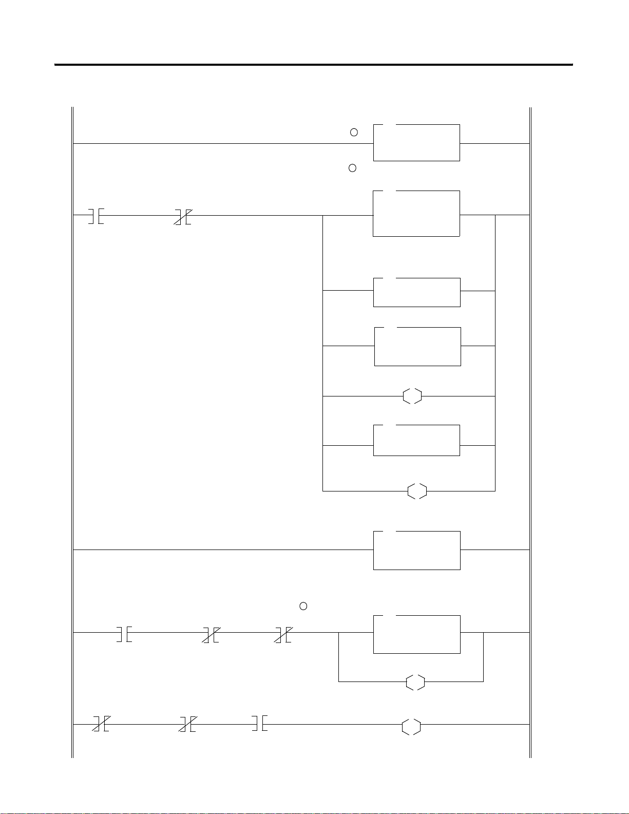
C-6 CIP Client Management
Your Precondition
Use a flag to notify that
a message is pending
B3:0
0
SLC 500 Ladder Program
Get an image of the CIP Message Control data
1
2
Jump into a subroutine that initializes N7 local
CIP control words (N7:0 to N7:8) or insert
instructions here.
Be sure the command data size word is null.
Copy the control data with EN bit set!
COP
Copy File
Source #M0:1.1000
Dest #N7:0
Length 10
There is no request data, just
clear the command word
FLL
Fill File
Source 0
Dest #N7:0
Length 10
JSR
Jump To Subroutine
SBR File Number U:3
MOV
Move
Source 0
Dest M0:1.1009
Be sure the EN bit is set
N7:0
L
15
COP
Source #N7:0
Dest #M0:1.1000
Length 10
The message is pending
B3:0
L
0
If the bit Done is set without timeout or error ...
N7:0
13
When the precondition is not valid, the message is done
and if the message is not in continuous mode, reset the
bit DN
Your Precondition
N7:0 N7:0
11 13
Publication 1747-RM623D-EN-P - June 2006
4
N7:0 N7:0
8
12
Get an updated copy of the CIP Message Control word
MOV
Move
Source M0:1.1000
Dest N7:0
Get the response in N10 file.
Copy more data than expected in case of extended
Copy File
Source #M0:1.1350
Dest #N10:0
Length 32
status
COP
The message is completed
B3:0
U
0
Reset DN bit
M0:1.1000
U
13
41557
Page 67

CIP Client Management C-7
5
SLC 500 Processor: Data Files (hex)
N7:Message control image
RSLogix 500 window
Detail:
N7:0 = 0xA000:Control word with bits EN and DN set - Response
received
N7:23 = 0x18:Response length - 24 words
N10:Response data
RSLogix 500 window
Detail:
N10:0 to N10:23:Response data
IMPORTANT
The data format on the wire is Little Endian. RSLogix 500
software displays words so byte order is inverted on the
screen.
Publication 1747-RM623D-EN-P - June 2006
Page 68

C-8 CIP Client Management
Send a Set Attribute Single Request
This process is illustrated in the following example. The steps in the
process correspond to the steps in the illustrations following.
1. The CIP message control image is updated on a regular base.
2. Yo u want to send a Set Attribute Single to Data Attribute
(Attribute number 3) of assembly instance 6 (Input file words 1
to 32). The CIP message control area and command data are
initialized in an internal data file. The command data is copied
in M0 first, then the command word is cleared and, as a last
step, the message control area is copied into M0 with the EN bit
set to what will send the message on the wire.
3. Request and response are exchanged on the wire.
4. When the bit DN is set without an error or timeout, nlatch the
DN bit. No response data is expected in case of a successful
response.
The response is available in an SLC internal data file.
See the following list for assembly object instance numbers supported by the
Get and Set Attribute Single services on Data attribute.
Instance 5 : Output file words 1 to 32
Instance 6 : Input file words 1 to 32
Publication 1747-RM623D-EN-P - June 2006
Page 69

SLC 500 Processor: N7 Data File (hex)
RSLogix 500
CIP Client Management C-9
Detail:
N7:0 = 0x8000:Control word with bit EN set
N7:1 = 0x08:Target MAC ID - Node 8
N7:2 = 0x200:Timeout 512 ms
N7:3 = 0x0:Complex IOI size - Not used
N7:4 = 0x10:Set Attribute Single service code
N7:5 = 0x04:Target Class code - Assembly object class
N7:6 = 0x06:Target Instance number - Instance 6: Input File
N7:7 = 0x03:Target Attribute number - Data Attribute
N7:8 = 0x00:Target Member number - Not used
N7:9 = 0x20:Command Data size - 32 words of data at M0:1.1000
N7:10 to N10:40:Data - Copy 32 words of data to M0:1.1000
Publication 1747-RM623D-EN-P - June 2006
Page 70

C-10 CIP Client Management
Your Precondition
Use a flag to notify that
a message is pending
B3:0
0
5
Example: SLC 500 Ladder Program
Get an image of the CIP Message Control data
COP
Copy File
1
Source #M0:1.1000
Dest #N7:0
Length 10
Use a flag to notify when the
2
message slot is free.
FLL
Fill File
Source 0
Dest #N7:0
Length 10
Jump into a subroutine that initializes N7 local
CIP control words (N7:0 to N7:8) command data
size and command data field (N7:9 to N7:42) or
insert instructions here.
JSR
Jump To Subroutine
SBR File Number U:3
Copy the command data size and data field.
COP
Source #N7:9
Dest #M0:1.1100
Length 128
If the bit Done is set without timeout or error ...
N7:0
13
N7:0 N7:0
8
Be sure the EN bit is set
N7:0
L
Copy the control data with EN bit set!
Get an updated copy of the CIP Message Control word
Move
Source M0:1.1000
Dest N7:0
No response other than status is expected.
4
12
15
COP
Source #N7:0
Dest #M0:1.1000
Length 10
The message is pending
B3:0
L
0
MOV
The message is completed
B3:0
U
0
41559
Publication 1747-RM623D-EN-P - June 2006
Page 71

CIP Client Management C-11
IMPORTANT
When the #M0.e.yyyy address is used in ladder
instructions, e is the 1747-SCNR slot number in the SLC
rack. If you reuse this example, and your module is not in
slot number one, update all instr uctions with the current
appropriate number..
SLC 500 Processor: Target Input Data File (hex)
RSLogix 500
I:1 file is the image of target node 8 Input file.
Publication 1747-RM623D-EN-P - June 2006
Page 72

C-12 CIP Client Management
The 1747-SCNR at MAC ID 11 wrote 32 words into the input data file
of 1747-SCNR at MAC ID 8.
Send a Set Member Request
IMPORTANT
This process is illustrated in the following example. The steps in the
What’s Happening box correspond to the steps in the illustrations
following the What’s Happening box.
1. The CIP message control image is updated on a regular base.
2. You want to send a Set Member to Data Attribute (Attribute
number 3) of assembly instance 7 (Local Database at words
M0:701 to M0:956). The CIP message control area and command
data are initialized in an internal data file. The command data is
copied in M0 first, then the command word is cleared and, as a
last step, the message control area is copied into M0 with the EN
bit set to what will send the message on the wire.
3. Request and response are exchanged on the wire.
4. When the bit DN is set without an error or timeout, nlatch the
DN bit. No response data is expected in case of a successful
response.
The 1747-SCNR module at MAC ID 8 must be in program
mode to write to the input data file.
The response is available in an SLC internal data file.
See the following list for assembly object instance numbers supported by the
Get and Set Attribute Single services on Data attribute.
Instance 5 : Output file words 1 to 31
Instance 6 : Input file words 1 to 31
Instance 7 : M0, ControlNet Data area words 0 to 1650
Instance 8 : M1, ControlNet Data area words 0 to 607
Publication 1747-RM623D-EN-P - June 2006
Page 73

SLC 500 Processor: N7 Data File (hex)
RSLogix 500
CIP Client Management C-13
Detail:
N7:0 = 0x8000:Control word with bit EN set
N7:1 = 0x08:Target MAC ID - Node 8
N7:2 = 0x200:Timeout 512 ms
N7:3 = 0x0:Complex IOI size - Not used
N7:4 = 0x19:Set Member service code
N7:5 = 0x04:Target Class code - Identity object class
N7:6 = 0x07:Target Instance number - Instance 7: M0 File
N7:7 = 0x03:Target Attribute number - Data
N7:8 = 0x2BD:Target Member number - 701, one based offset, M0 File
Local Database word 700
N7:9 = 0x41:Command Data size - 65 = 1 data length word + 64 words
of actual data, copy to M0:1.1100
N7:10 to N7:75:Data copied to M0:1.1100
IMPORTANT
The set member service contains the amount of data to be
written in N7:10, followed by the actual data values.
The length contained in N7:9 includes the size word of N7:10,
plus the number of data words to be sent.
Publication 1747-RM623D-EN-P - June 2006
Page 74

C-14 CIP Client Management
Your Precondition
Use a flag to notify that
a message is pending
B3:0
0
Example: SLC 500 Ladder Program
Get an image of the CIP Message Control data
COP
Copy File
1
Source #M0:1.1000
Dest #N7:0
Length 10
Use a flag to notify when the
2
message slot is free.
FLL
Fill File
Source 0
Dest #N7:0
Length 10
Jump into a subroutine that initializes N7 local
CIP control words (N7:0 to N7:8) command data
size and command data field (N7:9 to N7:75) or
insert instructions here.
JSR
Jump To Subroutine
SBR File Number U:3
Copy the command data size and data field.
COP
Source #N7:9
Dest #M0:1.1100
Length 128
If the bit Done is set without timeout or error ...
N7:0
13
N7:0 N7:0
8
Be sure the EN bit is set
N7:0
L
Copy the control data with EN bit set!
Get an updated copy of the CIP Message Control word
Move
Source M0:1.1000
Dest N7:0
No response other than status is expected.
4
12
15
COP
Source #N7:0
Dest #M0:1.1000
Length 10
The message is pending
B3:0
L
0
MOV
The message is completed
B3:0
U
0
41559
Publication 1747-RM623D-EN-P - June 2006
Page 75
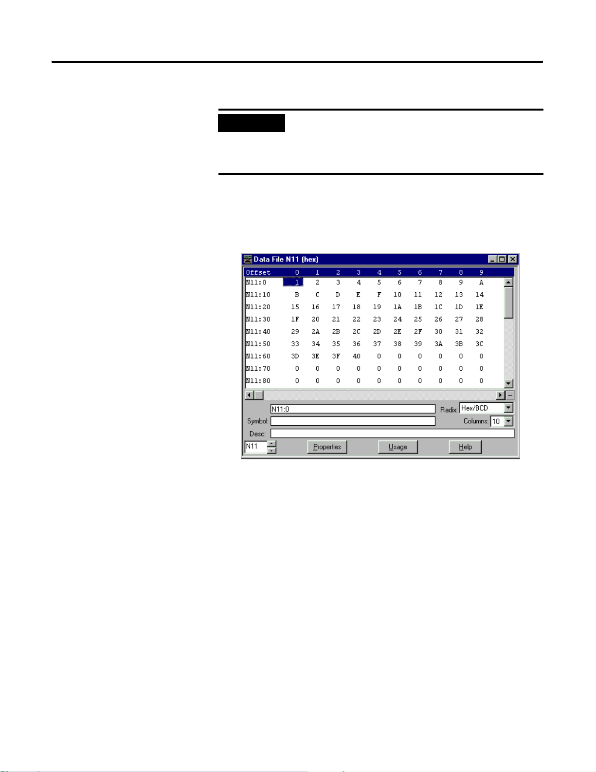
CIP Client Management C-15
IMPORTANT
When the #M0.e.yyyy address is used in ladder
instructions, e is the 1747-SCNR slot number in the SLC
rack. If you reuse this example, and your module is not in
slot number one, update all instr uctions with the current
appropriate number
SLC 500 Processor: Target Input Data File (hex)
RSLogix 500
N11 file is the image of target node 8 Local Database.
The 1747-SCNR at MAC ID 11 wrote 64 words into the Local Database
of 1747-SCNR at MAC ID 8.
Publication 1747-RM623D-EN-P - June 2006
Page 76

C-16 CIP Client Management
Notes:
Publication 1747-RM623D-EN-P - June 2006
Page 77

Appendix D
Example of Reset Bit Management
What This Appendix Contains
What We Assume
Example
This appendix contains an example of how you can use the
ladder program to reset a 1747-SCNR module located in the SLC
500 rack.
We assume that you are familiar with ladder programming.Reset
bit management is illustrated in the following example. The
steps in the procedure correspond to the steps in the illustration
following.
Reset bit management is illustrated in the following example.
The steps in the procedure correspond to the steps in the
illustration.
1. In this example, we reset the scanner when it is faulted.
When the 1747-SCNR sets its fault bit, the scanner slot
(slot 3) is disabled and the Output Command word Reset
bit is set (O:3.0/8).
2. When the slot is disabled, a timer is started and four
seconds later the scanner is enabled.
During these four seconds, you must avoid any access to
the scanner in reset. This is why the rung with the TND
instruction must be executed first.
IMPORTANT
1 Publication 1747-RM623D-EN-P - June 2006
If you do not disable the slot while the scanner is
resetting, the SLC module faults with the error code
nn57h (speciality, I/O Module in slot nn has not
responded to a lock shared memory command in the
requested time limit) where nn is the slot number of
the scanner. This is why the reset bit change is not
taken into account until the slot is disabled.
Page 78

D-2 Example of Reset Bit Management
If the module in slot 3 is not enabled, no access to
the module is allowed
S2:11
3
2
Use a timer to re-enable the module after a 4
seconds delay.
TON
Timer On Delay
Timer T4:0
Timer Base 1.0
Preset 4
Accum 0
Enable the module 4 seconds after the reset
bit has been set.
T4:0
EN
DN
S2:11
L
Example: If the module in slot 3 is faulted, reset it.
I:3
0
Your Precondition1
Your Precondition2
DN
During a reset operation, use a TND or any
other instruction to avoid executing all
instructions that access the module.
Set the Reset bit in Output Command Word
1
XOR
Bitwise Exclusive OR
Source A O:3.0
Source B 256
Length O:3.0
Disable the 1747-SCNR module in Slot 3
S2:11
3
TND
U
3
41558
Publication 1747-RM623D-EN-P - June 2006
IMPORTANT
In this ladder example, when S2:11\e, I:e\0 or O: e.0
are used, e is the 1747-SCNR slot number in the SLC
rack. If you reuse this example and your module is
not in slot 3, update all instructions with the current
appropriate number.
Page 79

Application Examples
Appendix E
What This Appendix Contains
What We Assume
Example 1: Configure the 1747-SCNR Scanner with the 1746-IV16 Input Module
This appendix provides examples of applications and their use
with the 1747-SCNR scanner controlling discrete and analog data
on a ControlNet network via a 1747-ACNR15 and 1794-ACNR1 5
ControlNet adapter. Also included in this appendix is an
example of how to create peer-to-peer scheduled connections
between 1747-SCNR ControlNet scanners.
We assume that you are familiar with setting up a network and
working with RSLogix500, RSLinx, and RSNetWorx for
ControlNet software and the 1784-KTCX15 interface card.
The following example discusses how to configure the
1747-SCNR scanner with the 1746-IV16 input module.
Hardware Setup
The hardware setup for this examples includes a computer with
RSLogix500, RSLinx, RSNetWorx for ControlNet software, and a
1784-KTCX15 interface card. The chassis con f igu r atio n includes
a 1747-ACNR15 module in slot 0, 1746-IA16 module in slot 1,
1746-OB16 module in slot 2, and 1746-IV16 module in slot 3.
Configure the ControlNet Network with RSNetWorx
for ControlNet Software
Follow this procedure to configure the ControlNet network
using RSNetWorx for Co ntrolNet software.
1. Start RSNetWorx for ControlNet software by double
clicking its icon.
1 Publication 1747-RM623D-EN-P - June 2006
Page 80

E-2 Application Examples
You see this scr e en:
At this time, you can configure your ControlNet network
offline and then download it to the network. But in this
example, we go online and configure the network.
2. Go online by clicking the Online icon or by clicking the
Network menu and selecting Online.
Y ou see the Browse for Network window. In this window,
you must select the communication path previously
configured in RSLinx software for communicating with
your ControlNet network. For this example, a
1784-KTCX15 ControlNet PC card is used.
3. Click the 1784-KTCX15 card to select it.
4. Click OK.
Publication 1747-RM623D-EN-P - June 2006
Page 81

Application Examples E-3
The software attempts to communicate with all possible node
numbers on the network, from 1 to 99. The online network
screen appears. For this example, the screen should show node
99 as the programming terminal.
Node 1 is the 1747-SCNR scanner and node 3 is the
1747-ACNR15 module. The 1747-ACNR15 module resides in slot
0 of its chassis, while slot 1 contains a 1746-IA16 module, slot 2
contains a 1746-OB16 module, and slot 3 contains a 1746-IV16
module. For this example, a single 16-bit rack connection is
configured to read/write the three discrete I/O modules. Before
we create this connection, we should verify the chassis
configuration for the 1747-ACNR15 module. To do this:
5. Right-click the 1747-ACNR15 module.
6. Choose Edit Chassis and verify that the chassis configuration is
as follows:
• Slot 0: 1747-ACNR15
• Slot 1: 1746-IA16
• Slot 2: 1746-OB16
• Slot 3: 1746-IV16
Publication 1747-RM623D-EN-P - June 2006
Page 82

E-4 Application Examples
If the chassis is not already configured, manually configure it by
dragging the appropriate modules from the list on the right to
the proper slot on the left of the chassis configuration screen.
When this is complete, click APPLY and then OK.
Configure a Rack Connection
We are now re ady to configure the necessary ControlNet connection
so we can read/write data from the SLC processor to the remote
discrete I/O modules.
1. Click-right the 1747-SCNR scanner and choose Scanlist
Configuration.
You see a prompt to enter the Edit mode.
2. Click YES to see the following screen:
Publication 1747-RM623D-EN-P - June 2006
The 1747-SCNR scanner and 1747-ACNR15 module are shown as
nodes 1 and 3, respectively.
The three I/O modules are under the 1747-ACNR15 module in
slots 1 through 3 of the 1747-ACNR15 chassis.
3. To establish a 16-bit rack connection to the 1747-ACNR15
chassis, click-right the 1747-ACNR15 module and choose Insert
Connection.
Page 83

You see the following window.
Application Examples E-5
Note that addresses in the Connection Properties window are
already displayed in the fields. To have RSNetWorx for
ControlNet software, choose the next available valid I/O or
M-file addresses for all connections:
a. Click Auto Address Preferences.
b. Click the box next to Enable Automatic Addressing on Insert
so that a check mark appears in the box.
c. Click OK.
The Connection Name by default is Discrete 16 Bit Exclusive
Owner. This is the 16-bit rack connection we want. The first
available I/O addresses are I:3.1 and O:3.1, where the
1747-SCNR scanner is in slot 3 of the processor chassis. The first
available starting I/O addresses were placed into the Input
Address and Output Address fields, because automatic
addressing was previously selected in the Auto Address
Preference screen.
Publication 1747-RM623D-EN-P - June 2006
Page 84

E-6 Application Examples
Words I:3.0 and O:3.0 are reserved. Note that the input data
from the 1746-IA16 module is found in the processor’s input
image word I:3.3, the output data written to the 1746-OB16
module is from the processor’s output image word O:3.2, and
the input data from the 1746-IV16 module is in the processor’s
input image word I:3.5.
IMPORTANT
There is a two-word offset for input data for rack
connections. Therefore, for this example, the input data
for the input module in slot 1 of the remote 1747-ACNR15
chassis is written to I:3.3 in the SLC processor’s input
image and the input module in slot 3 is written to I:3.5.
The starting input address configured in RSNetWorx for
ControlNet software for this rack connection was I:3.1, but
I:3.1 and I:3.2 are used for status information. The Input
Size of 5 is shown in the Connection Properties screen.
The actual input data begins after the two words of status
information. I:3.4 is not used in this example because an
output module resides in slot 2. Also, note that there is no
offset for the outputs in a rack connection. O:3.2 is the
output image word written to the output module located
in slot 2 of the 1747-ACNR15 chassis. O:3.1 is also not
used in this example because an input card is in slot 1.
Y ou must also enter a value in the Status Address field. This field
supplies Connection Status information to the processor. The
starting bit address for this field must be an even number,
because two consecutive bits are used as status for each
connection. The even numbered bit indicates whether the
connection is open or closed and the odd numbered bit
indicates whether the connection is in normal operation or Idle
mode. In this example, the address chosen is the first available
bit pair, M1:3.600/00.
Publication 1747-RM623D-EN-P - June 2006
You have successfully configured a rack connection to the remote
chassis to communicate with the discrete I/O modules. At this point,
you may also configure the state of the outputs in the remote
ControlNet Chassis when the processor is placed into the Program
mode or if communications is lost to the remote chassis. This is
optional. The default is to turn all outputs off when one of the two
conditions occur. To select other options follow these steps.
a. Click the Advanced tab in the Connection Properties window.
Page 85

You see the following window.
Application Examples E-7
By default for rack connections, outputs in all slots in the remote
chassis are reset if the processor is placed into the Program
mode or if communications is lost for any reason. Two other
choices are offered:
• Hold Last State - all outputs remain in their last state if one of the
two conditions occur
• Safe State - lets you to choose exactly the state of each output
If Safe State is selected, you must click the Configuration Settings
tab and enter your Safe State data for each output word in
decimal. Then, whenever the SLC processor is placed into the
Program mode or if communications is lost to the 1747-ACNR15
adapter, the outputs revert to the Safe State data you entered for
each output word.
b. Click APPLY.
c. Click OK.
Publication 1747-RM623D-EN-P - June 2006
Page 86

E-8 Application Examples
The Connection Properties window closes and the Scanlist
Configuration window should look like the following:
You hav e no w successfully configured a rack connection to read/
write data between the SLC processor and the remote ControlNet
chassis. All that remains is to save the configuration to the network
keeper, which in this case is the 1747-SCNR scanner.
1. Click the Save icon or click the File menu and then Save.
You are pro mpted to Optimize and re-write schedule for all
connections.
2. Click OK.
3. Click YES.
Your ne two rk con f igu ration information is now written to the
network keeper.
The display on the front of your 1747-SCNR scanner should
show an image of a full glass next to the word I/O. This
indicates that all configured connections have been successfully
downloaded to the scanner. In addition, the A and OK LEDs
should be solid green and the B LED should be off, unless you
are using the redundant media option, which is not being used
in this example. The 1747-ACNR15 module should be displaying
that it is active (ACTV) and its LEDs should be solid green for A
and OK and the B LED should be off.
Publication 1747-RM623D-EN-P - June 2006
Page 87

Application Examples E-9
Creating a Ladder Program
The final step is to write a ladder program for the SLC processor,
including configuring the 1747-SCNR scanner for slot 3 of the
processor’s chassis.
1. After downloading the program to your processor, place it into
the Run mode.
2. Set the Run/Idle bit (O;e.0/10, where e=slot number of your
1747-SCNR scanner) to a 1.
Your program shou ld no w be able to read data from the
1746-IA16 in word I:3.3, write to the 1746-OB16 in word O:3.2
and read data from the 1746-IV16 in word I:3.5.
Example 2: Configure the 1747-SCNR Scanner with the 1746-NIO4V Analog Input/Output Module
The following example discusses how to configure the 1747-SCNR
scanner with the 1746-NIO4V combination analog input/output
module.
Hardware Setup
The hardware setup for this examples includes a computer with
RSLogix500, RSLinx, RSNetWorx for ControlNet software, and a
1784-KTCX15 interface card. The chassis configuration includes a
1747-ACNR15 module in slot 0, 1746-IA16 module in slot 1,
1746-OB16 module in slot 2, and 1746-NIO4V module in slot 3.
Configure the ControlNet Network with RSNetWorx
for ControlNet Software
Follow the procedure below to configure the ControlNet network
using RSNetWorx for ControlNet software.
1. Start RSNetWorx for ControlNet software by double-clicking its
icon.
Publication 1747-RM623D-EN-P - June 2006
Page 88

E-10 Application Examples
You see this scr e en:
At this time, you can configure your ControlNet network offline
and then download it to the network. But in this example, we
go online and configure the network.
2. Go online by clicking the Online icon or by clicking the
Network menu and selecting Online.
You see the Browse for Network window. In this window, you
must select the communication path previously configured in
RSLinx software for communicating with your ControlNet
network. For this example, a 1784-KTCX15 ControlNet PC card
is used.
3. Click the 1784-KTCX15 card to select it.
4. Click OK.
Publication 1747-RM623D-EN-P - June 2006
Page 89

Application Examples E-11
The software attempts to communicate with all possible node
numbers on the network, from 1 to 99. The online network
screen appears. For this example, the screen should show node
99 as the programming terminal as shown below.
Node 1 is the 1747-SCNR scanner and node 3 is the
1747-ACNR15 module. The 1747-ACNR15 module resides in slot
0 of its chassis, while slot 1 contains a 1746-IA16 module, slot 2
contains a 1746-OB16 module, and slot 3 contains a 1746-NIO4V
module. For this example, two separate ControlNet connections
are configured. The first is a Discrete 16-Bit Exclusive-Owner
rack connection for the two discrete I/O modules. The second
will be a Module Connection to the 1746-NIO4V 2 input/2
output analog module. Before we create this connection, we
should verify the chassis configuration for the 1747-ACNR15
module. To do this:
5. Right-click the 1747-ACNR15 module.
6. Choose Edit Chassis and verify that the chassis configuration is
as follows:
• slot 0: 1747-ACNR15
• slot 1: 1746-IA16
• slot 2: 1746-OB16
• slot 3: 1746-NIO4V
Publication 1747-RM623D-EN-P - June 2006
Page 90

E-12 Application Examples
If the chassis is not already configured, manually configure it by
dragging the appropriate modules from the list on the right to
the proper slot on the left of the chassis configuration screen.
When this is complete, click APPLY and then OK.
Configure a Rack Connection
We are now re ady to configure the necessary ControlNet connection
so we can read/write data from the SLC processor to the discrete I/O
modules and to the analog I/O module.
1. Right-click the 1747-SCNR scanner and choose Scanlist
Configuration.
You are prompted to enter the Edit mode.
2. Click YES.
You see the following screen:
Publication 1747-RM623D-EN-P - June 2006
The 1747-SCNR and 1747-ACNR15 modules are shown as no des
1 and 3, respectively. The three I/O modules are under th e
1747-ACNR15 module in slots 1 through 3 of the 1747-ACNR15
chassis.
3. To establish a 16-bit rack connection to the 1747-ACNR15
chassis, right-click the 1747-ACNR15 module and choose Insert
Connection.
Page 91

You see the following window.
Application Examples E-13
Note that addresses in the Connection Properties window are
already displayed in the fields. To have RSNetWorx for
ControlNet software choose the next available, valid
I/O or M-file addresses for all connections:
a. Click the Auto Address Preferences button.
b. Click the box next to Enable Automatic Addressing on Insert
so that a check mark appears in the box.
c. Click OK.
The Connection Name by default is Discrete 16 Bit Exclusive
Owner. This is the 16-bit rack connection we want. The first
available I/O addresses are I:3.1 and O:3.1, where the
1747-SCNR scanner is in slot 3 of the processor chassis. The first
available starting I/O addresses have been placed into the Input
Address and Output Address fields, because automatic
addressing was previously selected in the Auto Address
Preference screen.
Publication 1747-RM623D-EN-P - June 2006
Page 92

E-14 Application Examples
Words I:3.0 and O:3.0 are reserved. Note that the input data
from the 1746-IA16 is found in the processor’s input image word
I:3.3, the output data written to the 1746-OB16 module will be
from the processor’s output image word O:3.2.
IMPORTANT
There is a two-word offset for input data for rack
connections. Therefore, for this example, the input data
for the input module in slot 1 of the remote 1747-ACNR15
chassis will be written to I:3.3 in the SLC processor’s input
image.
The starting input address configured in RSNetWorx for
ControlNet software for this rack connection was I:3.1, but
I:3.1 and I:3.2 are used for status information. Therefore,
the actual input data begins after the two words of status
information. I:3.4 is not used in this example because an
output module resides in slot 2.
Also, note that there is no offset for the outputs in a rack
connection. O:3.2 is the output image word written to the
output module located in slot 2 or the 1747-ACNR15
chassis. In addition, no offset applies to module
connections at all. For this example, the input and output
data for the 1746-NIO4V module is located in M1:3.3,
M1:3.4, M0:3.3, and MO:3.4. M1:3.3 and MO:3.3 are the
starting addresses entered in RSNetWorx for ControlNet
software for the module connection.
Y ou must also enter a value in the Status Address field. This field
supplies Connection Status information to the processor for each
unique connection. The bit address for this field must be an
even number, because two consecutive bits are used as status
for each connection. The even numbered bit indicates whether
the connection is open or closed and the odd numbered bit
indicates whether the connection is in normal operation or Idle
mode. In this example, the starting address chosen is the first
available bit, M1:3.600/00.
Publication 1747-RM623D-EN-P - June 2006
You have successfully configured a rack connection to the remote
chassis to communicate with the two discrete I/O modules. At this
point, you may also configure the state of the outputs in the remote
ControlNet Chassis when the processor is placed into the Program
Mode or if communications is lost to the remote chassis. This is
optional. The default is to turn all outputs off when one of the two
conditions occur. To select other options:
a. Click the Advanced tab in the Connection Properties window.
Page 93
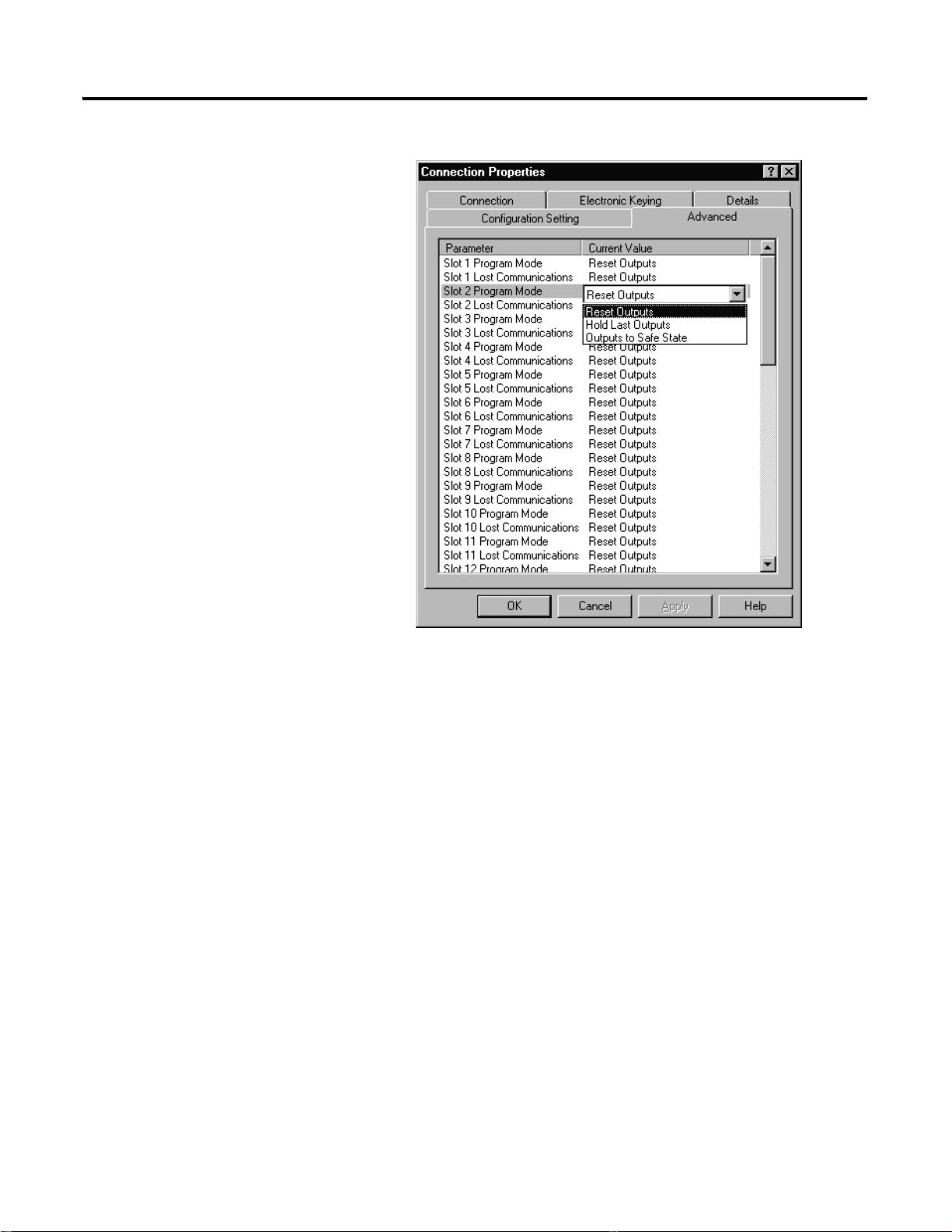
You see the following window.
Application Examples E-15
By default, outputs in all slots in the remote chassis are reset if
the processor is placed into the Program mode or if
communications is lost for any reason. Two other choices are
offered:
• Hold Last State - all outputs remain in their last state if one of the
two conditions occur
• Safe State - lets you to choose the st ate of each output
If Safe State is selected, you must click the Configuration Settings
tab and enter your Safe State data for each output word in
decimal. Then, whenever the SLC processor is placed into the
Program Mode or if communications is lost to the 1747-ACNR15
adapter, the outputs revert to the Safe State data you entered for
each output word.
b. Click APPLY.
c. Click OK to return to the Scanlist Configuration screen.
Publication 1747-RM623D-EN-P - June 2006
Page 94

E-16 Application Examples
Configure a Module Connection
Next, we need to configure a module connection for the 1746-NIO4V
module, 2 input/2 output module.
1. Right-click the 1746-NIO4V module in the Scanlist Configuration
window.
2. Select Insert Connection.
A Connection Properties window appears.
3. Choose Exclusive Owner for the connection name.
For this example, we must choose M-file addresses for our 2
input/2 output analog module. The first available M-file
addresses are M1:3.3 and M0:3.3. Words 0 through 2 are
reserved. The next available Status Address is M1:3.600/02, since
bits 0 and 1 are used for the rack connection. The Connection
Properties window for the module connection should look like
the following:
Publication 1747-RM623D-EN-P - June 2006
Page 95

Application Examples E-17
At this point, the state of the two analog outputs should be
determined and set in the Advanced and Configuration Settings
tabs in the Connection Properties window for this module
connection, provided you do not want the default settings of 0
decimal. This is the same as we did for discrete outputs for the
rack connection. This merely determines the state of the two
analog outputs when the SLC processor is placed in the Program
mode or if communications is lost to the 1747-ACNR15 module.
4. Click APPLY.
5. Click OK.
The Connection Properties window closes and the Scanlist
Configuration window appears and looks like the following.
You have successfully configured your two connections to read/write
data between the SLC processor and the remote ControlNet chassis.
All that remains is to save the configuration to the network keeper,
which in this case is the 1747-SCNR scanner.
1. Click the Save icon or click the File menu and choose Save.
You ar e prompted to Optimize and re-write schedule for all
connections.
Publication 1747-RM623D-EN-P - June 2006
Page 96

E-18 Application Examples
2. Click OK.
3. Click YES.
Your ne two rk con figuration information are now written to the
network keeper.
The display on the front of your 1747-SCNR scanner should
show an image of a full glass next to the word I/O. This
indicates that all configured connections have been successfully
downloaded to the scanner. In addition, the A and OK LEDs
should be solid green and the B LED should be off, unless you
are using the redundant media option, which is not being used
in this example. The 1747-ACNR15 module should be displaying
that it is active (ACTV) and its LEDs should be solid green for A
and OK and the B LED should be off.
Creating a Ladder Program
The final step is to write a ladder program for the SLC processor,
including configuring the 1747-SCNR scanner for slot 3 of the
processor’s chassis.
1. After downloading the program to your processor, place it into
the Run mode.
Your pr ogram should now be able to read data from the
1746-IA16 in word I:3.3 and write to the 1746-OB16 in word
O:3.2. The analog input data will reside in words M1:3.3 and
M1:3.4, while the analog output data must be placed in words
M0:3.3 and M0:3.4.
Note that your ladder program should also contain an
unconditional rung with an OTE instruction addressed to the
1747-SCNR scanner’s Run/Idle bit, O:3.0/10 for this example.
When the SLC processor is placed into the Run mode, this rung
will set the 1747-SCNR scanner’s Run/Idle bit and place the
scanner into the Run mode as well. The scanner will begin
executing the configured connections when the Run/Idle bit is
set.
Example 3: Configure the 1747-SCNR Scanner with the 1746-NI8 Analog Input Module
Publication 1747-RM623D-EN-P - June 2006
The following example discusses how to configure the 1747-SCNR
scanner with the 17 46-NI8 analog input module.
Page 97

Application Examples E-19
Hardware Setup
The hardware setup for this examples includes a computer with
RSLogix500, RSLinx, RSNetWorx for ControlNet software, and a
1784-KTCX15 interface card. The chassis configuration includes a
1747-ACNR15 module in slot 0, 1746-IA16 module in slot 1,
1746-OB16 module in slot 2, and 1746-NI8 module in slot 3.
Configure the ControlNet Network with RSNetWorx
for ControlNet Software
Follow the procedure below to configure the ControlNet network
using RSNetWorx for ControlNet software.
1. Start RSNetWorx for ControlNet software by double clicking its
icon.
You see this screen:
At this time, you can configure your ControlNet network offline
and then download it to the network. But in this example, we
will go online and configure the network.
2. Go online by clicking the Online icon or by clicking the
Network menu and selecting Online.
You see the Browse for Network window.
Publication 1747-RM623D-EN-P - June 2006
Page 98

E-20 Application Examples
In this window, you must select the communication path
previously configured in RSLinx software for communicating
with your ControlNet network. For this example, a 1784-KTCX15
ControlNet PC card is used.
3. Click the 1784-KTCX15 card to select it.
4. Click OK.
The software will attempt to communicate with all possible node
numbers on the network, from 1 to 99. The online network
screen appears. For this example, the screen should show n ode
99 as the programming terminal as shown below.
Publication 1747-RM623D-EN-P - June 2006
Node 1 is the 1747-SCNR scanner and node 3 is the
1747-ACNR15 module . The 1747-ACNR15 mo dule resides in slot
0 of its chassis, while slot 1 contains a 1746-IA16, slot 2 co ntains
a 1746-OB16, and slot 3 contains a 1746-NI8. For this example,
two separate ControlNet connections will be configured. The
first will be a Discrete 16 Bit Exclusive Owner rack connection
for the two discrete I/O modules. The second will be a Module
Connection to the 1746-NI8 8 input analog module. Before we
create this connection, we should verify the chassis
configuration for the 1747-ACNR15 module. To do this:
5. Right-click the 1747-ACNR15 module.
Page 99

Application Examples E-21
6. Choose Edit Chassis and verify that the chassis configuration is
as follows:
• slot 0: 1747-ACNR15
• slot 1: 1746-IA16
• slot 2: 1746-OB16
• slot 3: 1746-NI8
If the chassis is not already configured, manu ally configure it b y
dragging the appropriate modules from the list on the right to
the proper slot on the left of the chassis configuration screen .
When this is complete, click APPLY and then OK.
Configure a Rack Connection
We are now ready to configure the necessary ControlNet connections
so we can read/write data from the SLC processor to the discrete I/O
modules and to the analog I/O module.
1. Right-click the 1747-SCNR scanner and choose Scanlist
Configuration.
You are prompted to enter the Edit mode.
2. Click YES.
You see the following screen:
Publication 1747-RM623D-EN-P - June 2006
Page 100

E-22 Application Examples
The 1747-SCNR and 1747-ACNR15 modules are shown as no des
1 and 3, respectively. The three I/O modules are under th e
1747-ACNR15 in slots 1 through 3 of the 1747-ACNR15 chassis.
3. To establish a 16-bit rack connection to the 1747-ACNR15
chassis, right-click the 1747-ACNR15 and choose ControlN et
Configuration.
You see the following window.
Publication 1747-RM623D-EN-P - June 2006
Note that addresses in the Connection Properties window are
already displayed in the fields. To have RSNetWorx for
ControlNet software choose the next available, valid I/O or
M-file addresses for all connections:
a. Click the Auto Address Preference s button.
b. Click the box next to Enable Automatic Addressing on Insert
so that a check mark appears in the box.
c. Click OK.
 Loading...