

Page 1

Installation Instructions
SLC ControlNet Scanner Module
Catalog Number 1747-SCNR
Use this document to help you install the ControlNet™ 1747-SCNR
Scanner module.
For information about See page
important user information 2
preventing electrostatic discharge 4
compliance to European Union Directives 4
related publications 5
module features 6
preparing the module for installation 7
selecting the ControlNet node address 8
inserting the 1747-SCNR scanner into the chassis 8
connecting to a ControlNet network 9
connecting programming terminal to ControlNet network 11
cables 12
applying chassis power 13
alphanumeric display 13
OK indicator and display mnemonics 14
status indicators 19
specifications 20
hazardous location approval 21
Publication 1747-IN059C-EN-P - September 2001
Page 2
2 SLC ControlNet Scanner Module
Important User Information
Because of the variety of uses for the products described in this
publication, those responsible for the application and use of this
control equipment must satisfy themselves that all necessary steps
have been taken to assure that each application and use meets all
performance and safety requirements, including any applicable
laws, regulations, codes and standards. In no event will
Allen-Bradley be responsible or liable for indirect or consequential
damage resulting from the use or application of these products.
Any illustrations, charts, sample programs and layout examples
shown in this publication are intended solely for purposes of
example. Since there are many variables and requirements
associated with any particular installation, Allen-Bradley does not
assume responsibility or liability (to include intellectual property
liability) for actual use based upon the examples shown in this
publication.
Allen-Bradley publication SGI-1.1, Safety Guidelines for the
Application, Installation and Maintenance of Solid-State Control
(available from your local Allen-Bradley office), describes some
important differences between solid-state equipment and
electromechanical devices that should be taken into consideration
when applying products such as those described in this publication.
Reproduction of the contents of this copyrighted publication, in
whole or part, without written permission of Rockwell Automation,
is prohibited.
Throughout this manual, notes may be used to make you aware of
safety considerations. The following annotations and their
accompanying statements help you to identify a potential hazard,
avoid a potential hazard, and recognize the consequence of a
potential hazard.
WARNING
Identifies information about practices or circumstances
that can cause an explosion in a hazardous
environment, w hi ch may lead to personal in jury or
death, property damage or economic loss.
ÿ
Publication 1747-IN059C-EN-P - September 2001
Page 3
SLC ControlNet Scanner Module 3
ATTENTION
ÿ
IMPORTANT
ATTENTION
ÿ
Identifies information about practices or circumstances
that can lead to person a l injury or death, property
damage or economic loss.
Identifies information that is critical for successful
application and understanding of the product.
Environment and Enclosure
This equipment is inte nded for use in a P ollut ion Degr ee
2 industrial environment, in overvoltage Category II
applications (as defined in IEC publication 60664-1), at
altitudes up to 2000 meter without derating.
This equipment is s uppl ied as “ope n typ e” eq uipm ent. It
must be mounted within an enclosure that is suitably
designed for t hose speci fic enviro nmental cond itions that
will be present and appropriately designed to prevent
personal injury resulting from accessibility to live parts.
The interior of the enclosure must be accessible only by
the use of a tool. Subsequen t sec tion s of th is public atio n
may contain additional information regarding specific
enclosure type ratings that are required to comply with
certain product safety certifications.
NOTE: See NEMA Standards publication 250 and IEC
publications 60529, as a pplicable, for ex planatio ns of t he
degrees of protection provided by different types of
enclosure. Also, see the appropriate sections in this
publication, as well as the Allen-Bradley publication
1770-4.1 (“Industrial Automation Wiring and Grounding
Guidelines”), for additional installation requirements
pertaining to this equipment.
Publication 1747-IN059C-EN-P - September 2001
Page 4

4 SLC ControlNet Scanner Module
Prevent Electrostatic Discharge
The scanner module is sensitive to electrostatic discharge.
ATTENTION
ÿ
Electrostati c discharge can damag e int eg rated circuits or
semiconductors if you touch backplane connector pins.
Follow these guidelines when you handle the module:
• touch a grounded object to discharge static potential
• wear an approved wrist-strap grounding device
• do not touch the backplane connector or connector
pins
• do not touch circuit components inside the module
• if available, use a static-safe work station
• when not in use, keep the module in its static-shield
bag
Compliance to European Union Directives
If this product has the CE mark, it is approved for installation within
the European and EEA regions. It has be en desi gned and tes ted to
meet the following directives.
EMC Directive
This product is tested to meet Council Directive 89/336/EEC
Electromagnetic Compatibility (EMC) and the following standards, in
whole or in part, documented in a technical construction file:
• EN 50081-2 EMC — Generic Emission Standard, Part 2 —
Industrial Environment
• EN 50082-2 EMC — Generic Immunity Standard, Part 2 —
Industrial Environment
This product is intended for use in an industrial environment.
Publication 1747-IN059C-EN-P - September 2001
Page 5

SLC ControlNet Scanner Module 5
Low Voltage Directive
This product is tested to meet Council Directive 73/23/EEC Low
Voltage by applying the safety requirements of EN 61131-2
Equipment Requirements and Tests.
For specific information required by EN 61131-2, see the appropriat e
sections in this publication as well as the following Allen-Bradley
publications:
• Industrial Automation Wiring and Grounding Guidelines,
publication 1770-4.1
• Automation Systems Catalog, publication B113
This equipment is classified as open equipment and must be
installed (mounted) in an enclosure as a means of providing safety
protection.
Related Publications
For: Refer to the: Publication:
software configuration
information
planning and installation
information
terminating ControlNet
coaxial cables information
1.The publication number listed includes only t he base number. The Automation Bookstore a nd Manuals On line
will list the latest version of the publication. For example, 1747-RM623C-EN-P.
ControlNet 1747-SCNR
Reference Manual
ControlNet Cable System
Planning and Installation Manual
Terminating Your ControlNet
Coaxial Cables
1747-RM623
1786-6.2.1
CNET-DM001
1
1
If you need a copy of these manuals, access the Automation
Bookstore website at http://www.theautomationbookstore.com or
the Manuals On line website at http://www.ab.com/manuals.
Publication 1747-IN059C-EN-P - September 2001
Page 6
6 SLC ControlNet Scanner Module
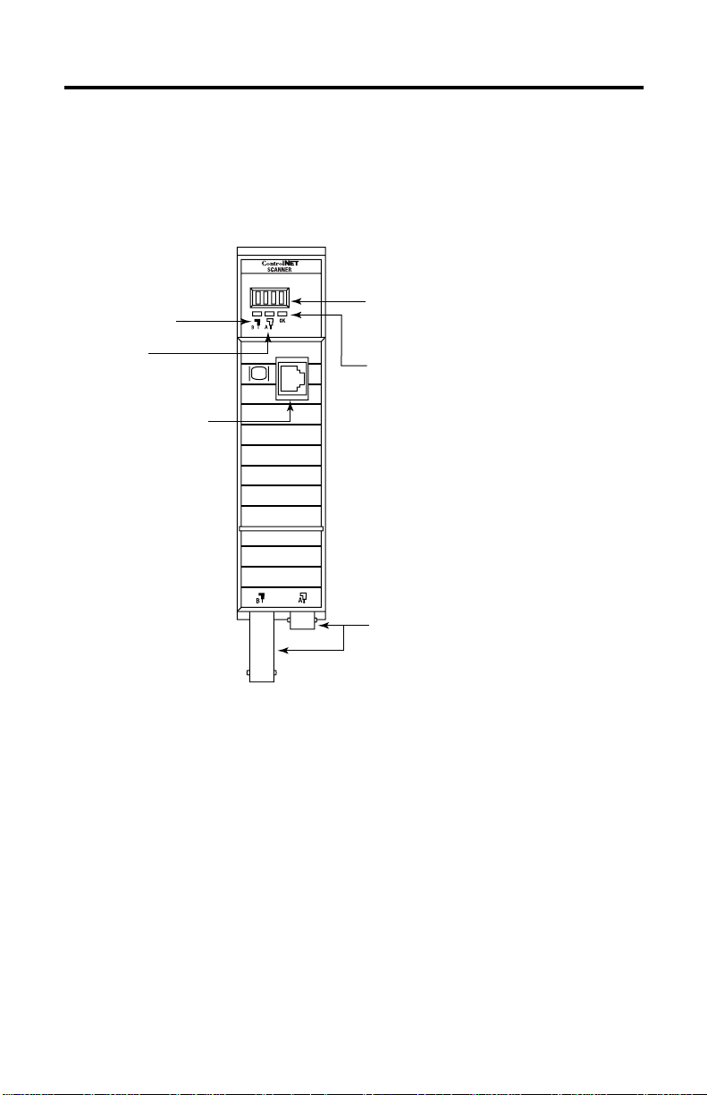
Identify Scanner Module Feat ures
Use this illustration to identify the features of the 1747-SCNR
Scanner module.
Node Address and Status Display
Channel B
Status Indicator
Displays scanner node address and status
Channel A
Status Indicator
ControlNet Network
Access Port
(NAP)-RJ45 connector
Module Status Indicator
Indicates whether the device is powered and is
functioning properly
ControlNet Redundant Media Ports
BNC connectors (Channels A and B)
30751-M
Publication 1747-IN059C-EN-P - September 2001
Page 7
SLC ControlNet Scanner Module 7
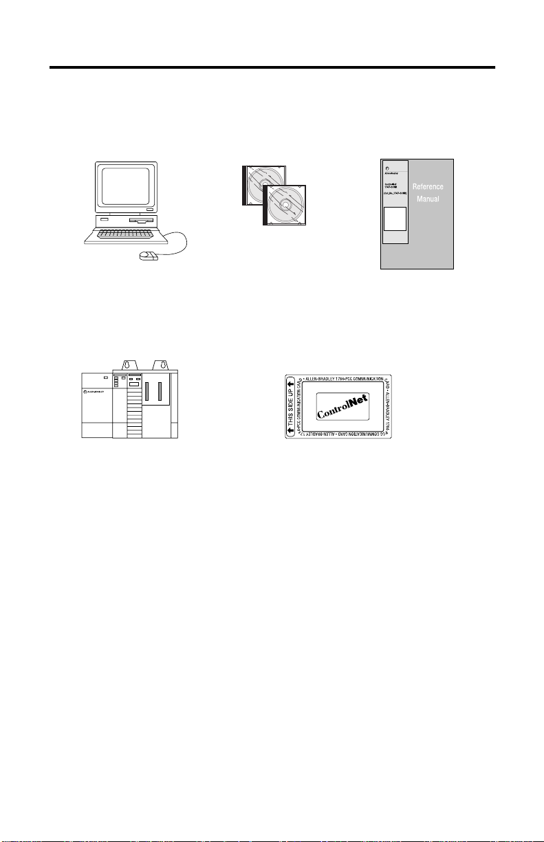
Prepare for Module Installation
Before you install your module, you need the following items:
RSNetWorx for
Personal Computer with
Windows
Microsoft
1746 chassis with SLC
SLC
5/02, 5/03, 5/04, or 5/05 processor and
the appropriate configuration software
(RSLogix 500
)
ControlNet
catalog number
9357-CNETL3
,
1747-SCNR Scanner Module
Reference Manual, publication
1747-RM623 (The publication
number includes the base number
only. The current versions will be
listed in the Automation
Bookstore and Manuals On line.)
ControlNet 1784-PCC (shown), or
1784-PCIC, or 1784-KTCX15, or
1770-KFC15
41523
Before you install the module, you must know how to:
• program and operate an Allen-Bradley SLC 500 programmable
controller
• install and configure the devices on your ControlNet network
Make Sure That Your Processor and Scanner Are Compatible
The 1747-SCNR Scanner module fits in any sl ot of the ch assis except
for the left-most slot of the first chassis, which is reserved for the
SLC 500 processor.
Publication 1747-IN059C-EN-P - September 2001
Page 8
8 SLC ControlNet Scanner Module
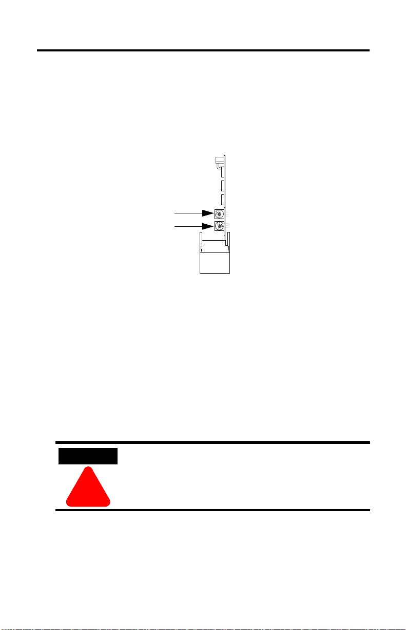
Select the ControlNet Node Address
Select the ControlNet node address of the 1747-SCNR by setting the
two 10-digit rotary switches on the top of the scanner. Valid switch
settings range from 01 through 99. Zero (00) is not a valid node
address.
10-digit rotary switches: ones digit
10-digit rotary switches: tens digit
30752
Important: Since 00 is the default value from man ufacturing, you
must change the default value when using the
scanner for the fir s t tim e .
Top View of Module
Insert the 1747-SCNR Scanner Into the Chassis
To insert the 1747-SCNR Scanner into the SLC chassis:
1. Turn off the SLC chassis power supply.
ATTENTION
ÿ
Important: If you disconnect the ac power, you lose the chassis
Publication 1747-IN059C-EN-P - September 2001
Do not install the 1747-SCNR Scanner module with
the chassis power supply on. Installing the module
with the chassis power supply on may damage the
module.
ground. Electrostatic damage (ESD) protection is lost.
Page 9

SLC ControlNet Scanner Module 9
2. Select a slot for the module in the chassis. Choose any slot
except the left-most slot of the first chassis, which is reserved
for the SLC 500 processor.
3. Insert the module into the slot you have selected. We
recommend that you insert the 1747 -SC NR Scanner as close to
the chassis power supply as possible.
30801-M
4. Apply firm, even pressure to seat the module in the I/O
chassis backplane connectors.
5. Restore power to the SLC chassis.
Connect to a ControlNet Network
Connect the 1747-SCNR Scanner module to a ControlNet network
via a tap with a 1m (39.4 in.) drop cable.
Publication 1747-IN059C-EN-P - September 2001
Page 10

10 SLC ControlNet Scanner Module
Four Allen-Bradley ControlNet taps are available from Rockwell
Automation as shown below.
Straight T-tap
Straight Y-tap
Right-angle T-tap
Right-angle Y-tap
1786-TPS
1786-TPYS
1786-TPR
1786-TPYR
20094-M
Important: Allen-Bradley ControlNet taps contain passive
electronics and must be purchased from Rockwell
Automation for the network to function properly.
After terminating your network segments, connect your node to the
network.
Nonredundant media
A
Redundant media
A
B
30802-M
WARNING
If you connect or disconnect the ControlNet cable with
power applied to this module or any device on the
network, an electric al arc can occur . Thi s could cause an
explosion in hazardous location installations. Be sure
ÿ
that power is removed or the area is nonhazardous
before proceeding.
Publication 1747-IN059C-EN-P - September 2001
Page 11

SLC ControlNet Scanner Module 11
Remove the tap’s dust cap—located on the straight or righ t-angle
connector—and set it aside.
If your network supports Connect the tap’s straight or right-angle connector
nonredundant media to the channel A connector on the scanner— channel
B is not used.
redundant media from trunk-cable A to channel A on th e scan ner and
from trunk-cable B to channel B on the scanner.
1. Rockwell Automation recommends using channel A for nonredundant media.
1
For detailed information about planning and installing your
ControlNet system, see the following information sources.
Source Source Number
ControlNet Coax Cable System Planning and Installation Manual 1786-6.2.1
ControlNet Media System Component List AG-2.2
ControlNet Coax Tap Installation Instructions 1786-5.7
ControlNet Network Access Cable Installation Instructions 1786-2.6
Industrial Automation Wiring and Grounding Guidelines 1770-4.1
Terminating Your ControlNet Coaxial Cables
1.The publication number listed includes only the base number. The Automation Bookstore and Manuals On
line will list the latest version of the publication. For example, CNET-DM001A-EN-P.
CNET-DM001
1
Connect Programming Terminal to ControlNet Network
Y ou can connect the programming terminal to a ControlNet network
through a:
• ControlNet product’s NAP using a network access cable
(1786-CP)
• tap on a ControlNet network
ATTENTION
ÿ
Use the 1786-CP c able when connec ting a scanner to
the network through a NAP. Using a commercially
available RJ-style cable could result in network
failure.
Publication 1747-IN059C-EN-P - September 2001
Page 12
12 SLC ControlNet Scanner Module
Cables
Several types of RG-6 quad-shield cables may be appropriate for
your ControlNet installation—depending on the environment factors
associated with your application and installation site.
The following Allen-Bradley ControlNet cable system components
are available from Rockwell Automation:
1
Item
ControlNet Coax Tool Kit - ControlNet Coax Tool (enables you to
make successful coaxial cables)
Coax Tap Kit Right-angle T-tap
Repeaters Dual channel coaxial repeater 1786-RPCD
Fiber Optic Repeaters
RG-6 Quad Shield Cable Standard-PVC CM-CL2 1786-RG6
ControlNet Network Access Cable–3.05 m (10 ft) 1786-CP
BNC Connectors Barrel (plug to plug) 1786-BNCP
1. For a complete list of Allen-Bradley ControlNet cable syste m component s th at a re availa ble f ro m Rockwell
Automation and cable system components available from other suppliers, see the ControlNet Media
System Component List, publication AG-2.2.
Straight T-tap
Right-angle Y-tap
Straight Y-tap
Low-voltage dc coax adapter 1786-RPA
Short-range fiber module 1786-RPFS
Medium-range fiber module 1786-RPFM
BNC/RG-6 plug 1786-BNC
Bullet (jack to jack) 1786-BNCJ
Isolated-bulkhead (jack to jack)1786-BNCJI
Terminators (BNC-75Ω) 1786-XT
Cat. No.
1786-CTK
1786-TPR
1786-TPS
1786-TPYR
1786-TPYS
Important: Install all wiring for your ControlNet system in
accordance with the regulations contained in NFP A 70
the National Electronic Code (or applicable count ry
codes), state codes, and applicable municipal codes.
For detailed information about ControlNet cabling, see the
ControlNet System Overview, publication CNET-SO001A-EN-P and
the publications listed in the table on the previous page.
Publication 1747-IN059C-EN-P - September 2001
Page 13

SLC ControlNet Scanner Module 13
Apply Chassis Power
Node Address and
Status Display
30750-M
When you apply chassis power, the module address and status
display cycles through the follow ing displays:
1. POST - The 1747-SCNR runs Power On Self Test.
2. 1111, 2222, etc. - The 1747-SCNR is executing its startup
sequence.
3. The 1747-SCNR firmware version is displayed temporarily after
startup.
4. A#nn (where nn = ControlNet node address) then I/O or
I/OX (based on the number of connections configured and
established) then IDLE or RUN (based on the scanner mode).
Alphanumeric Display
The four character alphanumeric display provides you with
additional visual information about the current operating status of
the module.
The following tables describes problems that may occur while using
your 1747-SCNR, the probable cau ses, and t he recommended actio n.
Publication 1747-IN059C-EN-P - September 2001
Page 14

14 SLC ControlNet Scanner Module
OK Indicator and Display Mnemonics
The OK indicator is handled consistently with the ControlNet
specifications for the Identity object.
Sequence OK
Indicator
Startup Alternately
red/ green
Run time Green A#XX N/A ControlNet
Alpanumeric
Display
POST N/A The
FIRM
WARE
I/O
IDLE N/A The scanner is
RUN N/A The scanner is
Module Status
Word (M1 file)
N/A 1747-SCNR
0x26 All configured
Description Probable
1747-SCNR
module is
running Power
On Self Test.
firmware
revision. This is
a temporary
display after
startup.
node address
connections
are
established.
in idle mode.
in run mode.
Cause
Power was
applied to the
module.
Power was
applied to the
module.
None No action
None No action
The SLC
processor or
adapter in
slot 0 is in
program
mode or the
Scanner
Mode
Command bit
of the Module
Command
word is clear
(O:x.0/10
where x is the
scanner slot
number).
The SLC
processor in
slot 0 is in run
mode and the
Scanner
mode
Command bit
of the Module
Command
word is set
(O:x.0/10).
Recommended
Action
No action
required.
No action
required.
required.
required.
If you want to
put the scanner
into run mode,
put the SLC
processor in
slot 0 into run
mode and set
the Scanner
Mode
Command bit of
the Module
Command word
(O:x.0/10) using
an
unconditional
OTE instruction.
If you want to
put the scanner
into program
mode, either
put the SLC
processor in
slot 0 into
program mode
or clear the
Scanner Mode
Command bit of
the Module
Command word
(O:x.0/10).
Publication 1747-IN059C-EN-P - September 2001
Page 15

SLC ControlNet Scanner Module 15
Sequence OK
Run time Green EDIT N/A The scanlist in
Indicator
Flashing
Green
Alpanumeric
Display
I/OX 0x20 The scanner is
Module Status
Word (M1 file)
0x21 The current
Description Probable
the
1747-SCNR is
being modified.
not configured.
configuration is
not valid.
The scanner is
not able to start
any scheduled
communication
to remote
devices. Only
unscheduled
communication
is possible.
Cause
Edits have
been enabled
with
RSNetWorx
for
ControlNet.
Note:
Previously
configured
connections
will be
reestablished
if lost. Newly
configured or
changed
connections
will not be
established
until edits are
accepted.
Module not
configured.
Module not
configured
properly.
Recommended
Action
Finish
modifying the
scanlist with
RSNetWorx for
ControlNet and
then accept
edits.
Cancel edits
with
RSNetWorx for
ControlNet.
Use RSNetWorx
for ControlNet
to download a
new
configuration.
Use RSNetWorx
for ControlNet
to schedule the
existing
configuration.
Use RSNetWorx
for ControlNet
to download a
new
configuration.
Publication 1747-IN059C-EN-P - September 2001
Page 16

16 SLC ControlNet Scanner Module
Sequence OK
Indicator
Run time Flashing
Green
Alpanumeric
Display
I/O
I/O
I/O
I/O
Module Status
Word (M1 file)
0x22
0x23
0x24
0x25
Description Probable
Connections
are configured
but no
connections
are
established.
Connections
are configured
but only
25% are
successfully
established.
50%
75%
Cause
View the
Connection
Status screen
in RSNetWorx
for ControlNet
to see why
the
connections
are not
established.
Module
bandwidth is
exceeded.
Recommended
Action
Check to see if
the 1747-SCNR
and the remote
devices are
correctly
connected to
the ControlNet
network.
Reduce the
number of
scheduled
connections by:
- using a
discrete rack
connection
instead of
multiple
discrete module
connections
- combining
multiple I/O
racks into a
single I/O rack
- combining
multiple
peer-to-peer
messages into
one message.
Increase your
Network Update
Time and/or
increase the
Requested
Packet Intervals
for scheduled
data transfers.
Increase your
SLC 500 ladder
program scan
by adding more
logic.
Publication 1747-IN059C-EN-P - September 2001
Page 17

SLC ControlNet Scanner Module 17
Sequence OK
Indicator
Run time Flashing
Green
Alpanumeric
Display
EDIT N/A The scanlist in
SIGM N/A A scanner
Module Status
Word (M1 file)
Description Probable
the 1747-SCNR
is being
modified.
signature
mismatch has
been detected.
The
1747-SCNR
scanner
signature does
not match the
signature
stored in the
active keeper.
The scanner is
not able to start
any scheduled
communication
to remote
devices. Only
unscheduled
communication
is possible.
Cause
Edits have
been enabled
with
RSNetWorx
for
ControlNet.
Note:
Previously
configured
connections
will be
reestablished
if lost. Newly
configured or
changed
connections
will not be
established
until edits are
accepted.
Module is not
configured
properly.
Recommended
Action
Finish
modifying the
scanlist with
RSNetWorx for
ControlNet and
then accept
edits.
Cancel edits
with
RSNetWorx for
ControlNet.
Use RSNetWo rx
for ControlNet
to schedule the
existing
configuration.
Use RSNetWorx
for ControlNet
to download a
new
configuration.
Publication 1747-IN059C-EN-P - September 2001
Page 18

18 SLC ControlNet Scanner Module
Sequence OK
Errors Off None N/A Module is not
Indicator
Flashing
Green
Red (Scrolling
Flashing
Red
Alpanumeric
Display
N/A 0x43 Network error Cable error or
display
showing fault
details)
A#00
FLSH
CFG
ERAS
DUPL
A#XX
Module Status
Word (M1 file)
N/A Module faulted Internal error
0x42 Module erased
0x44 Duplicate node
Description Probable
communicating
network and
connection
configuration
stored in flash
address
Cause
Power supply
fault.
no other
nodes on the
network.
detected.
Network node
address set
to 00.
Another
device with
the same
ControlNet
address is on
the link.
Recommended
Action
Check power
supply, cable
connectors, and
seat module
firmly in
chassis.
Verify network
cabling.
Record fault
details and
contact
Rockwell
Automation
representative
or distributor.
Power down
the module and
change the
address
switches.
Power down
the 1747-SCNR
module and
change the
network
address
switches to a
correct node.
Publication 1747-IN059C-EN-P - September 2001
Page 19

SLC ControlNet Scanner Module 19
Status Indicators
The ControlNet status indicators inform you of the operational state
of the ControlNet network.
Indicator
Color
1
Probable Cause Recommended Action
Off No power No action required or apply power.
A
and
B
Steady Red Faulty unit Cycle power or reset unit. If fault
persists, contact your Rockwell
Automation representative or
distributor.
Alternating
Self-test No action required.
Red/Green
Alternating
Red/Off
Incorrect node
configuration or
Check network address and other
ControlNet configuration parameters.
duplicate
ControlNet node
address
Off Channel disabled Program network for
A
or
B
Steady
Normal operation No action required.
redundant media, if required.
Green
Flashing
Green/Off
Temporary network
errors
• Check media for broken cables, loose
connectors, missing terminators, etc.
• If condition persists, refer to ContolNet
Cable Planning and Installation
Manual, publication 1786-6.2.1.
Flashing
Red/Off
Media fault • Check media for broken cables, loose
connectors, missing terminators, etc.
• If condition persists, refer to ContolNet
Cable Planning and Installation
Manual, publication 1786-6.2.1.
No other nodes
Add other nodes to the network.
present on network
Flashing
Red/Green
Incorrect node
address
Incorrect network
configuration
Change 1747-SCNR node address so that
it is less than or equal to SMAX
Reconfigure ControlNet network so that
2
is greater than or equal to
SMAX
1747-SCNR node address.
1. Definition of terms:
steady - indicator is on continuously in the defined state.
alternating - the two indicators alterna te between the two define d states at the same time (applies to
both indicators
flashing - the indicator alternates between the two defined states (applies to each indicator
independent
2. SMAX is the highest node address on a ControlNet network that can transmit scheduled data.
viewed together
of the other); if both indicators are flashing, they flash together, in phase.
); the two indicators are always in opposite states, out of phase.
viewed
2
.
Publication 1747-IN059C-EN-P - September 2001
Page 20

20 SLC ControlNet Scanner Module
Specifications
SLC ControlNet Scanner Module - 1747-SCNR
Module Location Slot 1 or above
Module Defaults Node Address -00
Maximum Backplane Current 900 mA @ 5V dc
Isolation Voltage O ptical Isolation between backplane and ControlNet
Environmental Conditions:
Operational Temperature
Storage Temperature
Relative Humidity
Shock unpackaged 30g operational
Vibration Unpackaged 5g from 10-150Hz
Immunity Radiated Fields 10 V/m
Agency Certification
(when product or packaging
is marked)
channel 1 Megohm resistor from ControlNet channel
to chassis
0-60°C (32-140°F)
-40 to 85°C (-40 to 185°F)
5-95% without condensation
50g non-operational
27 mHz-1000 mHz
c us
Listed Industrial Control Equipment for use in Class I
Division 2, groups A, B, C, D, Hazardous Locations. Suitable for
use in U.S. and Canada.
marked for all applicable directives
Reference Manual 1747-RM623
Publication 1747-IN059C-EN-P - September 2001
Page 21

SLC ControlNet Scanner Module 21
Hazardous Location Approval
The following information applies only to products marked
with Hazardous Location Approval, when operating in
hazardous locations:
Products marked “CL I, DIV 2, GP A, B, C, D” are suitable for use in
Class I Division 2 Groups A, B, C, D, Hazardous Locations and
nonhazardous locations only. Each product is supplied with
markings on the rating nameplate indicating the hazardous location
temperature code. When combining products within a system, the
most adverse temperature code (lowest “T” number) may be used to
help determine the overall temperature code of the system.
Combinations of equipment in your system are subject to
investigation by the local Authority Having Jurisdicti on at the time of
installation
.
WARNING
ÿ
EXPLOSION HAZARD -
• Do not disconnect equipm ent unl ess p ower ha s been
removed or the area is known to be nonhazardous.
• Do not disconnect connections to this equipment
unless power has been remov ed or the ar ea is known
to be nonhazardous. Secure any external connect ions
that mate to this equipment by using screws, sliding
latches, threaded connectors, or other means
provided with this product.
• Substitution of components may impair suitability for
Class I, Division 2.
• If this product contains batteries, they must only be
changed in an area known to be nonhazardous.
Publication 1747-IN059C-EN-P - September 2001
Page 22

22 SLC ControlNet Scanner Module
Les informations suivantes ne concernent que les produits
marqués pour une utilisation en environnements dangereux :
Les produits marqués « CL I, DIV 2, GP A, B, C, D » ne conviennent
qu’à une utilisation en environnements de Classe I Division 2
Groupes A, B, C, D dangereux et non dangereux. Chaque produit
est livré avec des marquages sur sa plaque d’identific ation qui
indiquent le code de température pour les environnements
dangereux. Lorsque plusieurs produits sont combinés dans un
système, le code de température le plus défavorable (code de
température le plus faible) peut être utilisé pour déterminer le code
de température global du système. Les combinaisons d’équipements
dans le système sont sujettes à inspection par les autorités locales
qualifiées au moment de l’installation.
AVERTISSEMENT
ÿ
RISQUE D’EXPLOSION -
• Couper le courant ou s’assurer que l’environnement
est classé non dangereux avan t de débrancher
l’équipement.
• Couper le courant ou s’assurer que l’environnement
est classé non dangereux avant de débrancher les
connecteurs. Fixer tous les connecteurs externes
reliés à cet équipement à l’aide de vis, loquets
coulissants, connecteurs filetés ou autres moyens
fournis avec ce prod ui t.
• La substitution de composants peut rendre cet
équipement inadapté à une utilisation en
environnement de Classe I, Division 2.
• S’assurer que l’environnement est classé non
dangereux avant de changer les piles.
Publication 1747-IN059C-EN-P - September 2001
Page 23

Notes:
SLC ControlNet Scanner Module 23
Publication 1747-IN059C-EN-P - September 2001
Page 24

Allen-Bradley is a registered trademark of Rockwell Automation.
SLC is a trademark of Rockwell Automation.
ControlNet is a trademark of ControlNet International.
Microsoft Windows is a registered trademark of Microsoft Corporation.
RSNetWorx for ControlNet and RSLogix 500 are trademarks of Rockwell Software, Inc.
CSA logo is a registered trademark of the Canadian Standards Association.
Le sigle CSA est la marque déposée de l'Association des Standards pour le Canada.
Publication 1747-IN059C-EN-P - September 2001 PN 957603-68
Supersedes Publication 1747-IN059B-EN-P - February 2001 © 2001 Rockwell Automation. Printed in the U.S.A.
 Loading...