

Page 1

ALLEN–BRADLEY
The Getting Started Guide for HHT
(Catalog Number 1747–PTA1E & 1747–PT1)
User Manual
Page 2

Important User Information
Solid state equipment has operational characteristics differing from those of
electromechanical equipment. “Safety Guidelines for the Application,
Installation and Maintenance of Solid State Controls” (Publication SGI-1.1)
describes some important differences between solid state equipment and
hard–wired electromechanical devices. Because of this difference, and also
because of the wide variety of uses for solid state equipment, all persons
responsible for applying this equipment must satisfy themselves that each
intended application of this equipment is acceptable.
In no event will the Allen-Bradley Company be responsible or liable for
indirect or consequential damages resulting from the use or application of
this equipment.
The examples and diagrams in this manual are included solely for illustrative
purposes. Because of the many variables and requirements associated with
any particular installation, the Allen-Bradley Company cannot assume
responsibility or liability for actual use based on the examples and diagrams.
No patent liability is assumed by Allen-Bradley Company with respect to use
of information, circuits, equipment, or software described in this manual.
Reproduction of the contents of this manual, in whole or in part, without
written permission of the Allen-Bradley Company is prohibited.
Throughout this manual we use notes to make you aware of safety
considerations.
ATTENTION: Identifies information about practices or
circumstances that can lead to personal injury or death, property
!
damage, or economic loss.
Attentions help you:
• identify a hazard
• avoid the hazard
• recognize the consequences
Important: Identifies information that is especially important for successful
application and understanding of the product.
PLC, PLC 2, PLC 3, and PLC 5 are registered trademarks of Allen-Bradley Company, Inc.
SLC, SLC 500, PanelView, RediPANEL, and Dataliner are trademarks of Allen-Bradley Company, Inc.
IBM is a registered trademark of International Business Machines, Incorporated.
Page 3

Preface
Preface
Read this preface to familiarize yourself with the rest of the manual. This
preface covers the following topics:
• who should use this manual
• the purpose of this manual
• how to use this manual
• conventions used in this manual
• Allen–Bradley support
Who Should Use this Manual
Purpose of this Manual
Use this manual if you are responsible for designing, installing,
programming, or troubleshooting control systems that use Allen–Bradley
small logic controllers.
You should have a basic understanding of SLC 500 products. You should
understand programmable controllers and be able to interpret the ladder logic
instructions required to control your application. If you do not, contact your
local Allen–Bradley representative for information on available training
courses before using this product.
This manual is a learning and reference guide for the HHT. It is an
introductory document, designed to allow you to begin programming in the
shortest time possible. It does this by focusing on a simple controller and a
simple program. Basic concepts are presented, but only with enough detail
to get you started and let you know that there is more to be learned.
P–1
Page 4

Preface
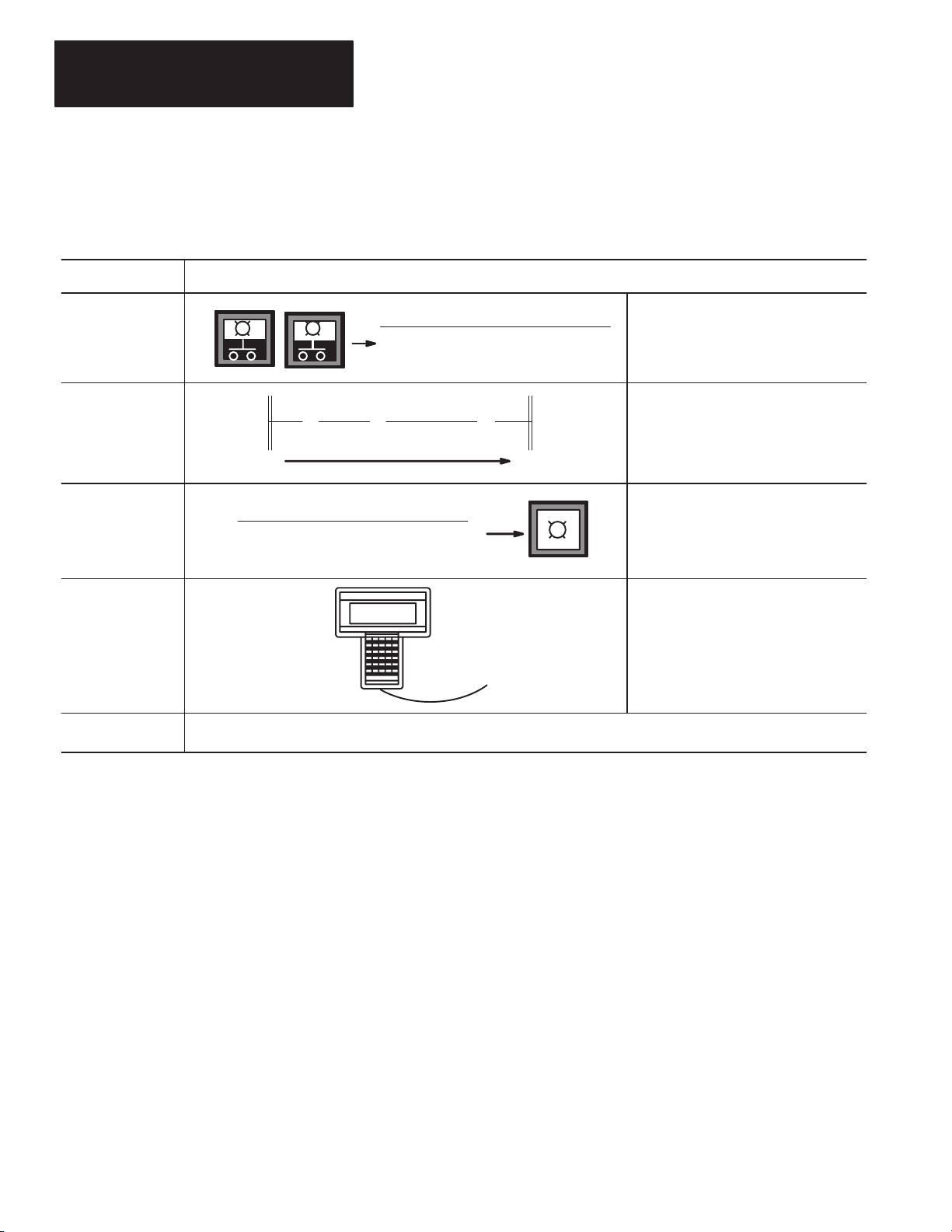
Contents of this Manual
Chapter: Title: Purpose:
Shows you how to set up a controller, install your
1 Setting Up Your Equipment
Memory Pak, Battery, and communication cable,
and connect your HHT to the controller.
2 Control Basics
3 Creating a Program Shows you how to create a program.
4 Online Operations
Appendix
A
Appendix
B
AppendixCIdentifying HHT Function Keys
Glossary Glossary Provides definitions of terms used in this guide.
Additional Ladder Program
Exercises
Troubleshooting Errors
& Instruction Mnemonics
Presents basic information you will need to know
before you can begin programming with the HHT.
Shows you how to download (restore) your program
to the controller, monitor, and test the program.
Introduces you to branching of instructions and the
timer instruction.
Provides a listing of error messages that you may
encounter while working through the guide. Also,
offers possible solutions for these errors.
Provides a listing of HHT function keys and their
meaning. Also provided is a list of instruction
mnemonics.
Related Documentation
The following documents contain additional information concerning
Allen–Bradley SLC and PLC products. To obtain a copy, contact your local
Allen–Bradley office or distributor.
For Read this Document
An overview of the SLC 500 family of products SLC 500 System Overview 1747–2.30
Document
Number
A description on how to install and use your Modular SLC 500
programmable controller
A description on how to install and use your Fixed SLC 500
programmable controller
A procedural and reference manual for technical personnel who use an
HHT to develop control applications
A complete listing of current Automation Group documentation, including
ordering instructions. Also indicates whether the documents are
available on CD–ROM or in multi–languages.
A glossary of industrial automation terms and abbreviations Allen–Bradley Industrial Automation Glossary ICCG–7.1
P–2
Installation & Operation Manual for Modular Hardware
Style Programmable Controllers
Installation & Operation Manual for Fixed Hardware Style
Programmable Controllers
Allen–Bradley Hand–Held Terminal User’s Manual 1747–809
Automation Group Publication Index SD499
1747–804
1747–800
Page 5

Preface
How to Use this Manual
Common Techniques Used in this Manual
Allen–Bradley Support
To use this manual effectively:
• Work through the chapters in sequential order, completing each one
before moving on to the next.
• Perform the exercises in appendix A to apply what you have learned in
the chapters.
• Consult appendix B to correct and identify any errors you encounter while
working through this manual.
• Refer to the glossary for definitions of unfamiliar terms.
• Use the index to locate further information on topics.
The following conventions are used throughout this manual:
• Bulleted lists such as this one provide information, not procedural steps.
• Numbered lists provide sequential steps or hierarchical information.
• Italic type is used for emphasis.
• Text in this
font
indicates words or phrases you should type.
• Key names match the names shown and appear in bold, capital letters
within brackets (for example,
Allen–Bradley offers support services worldwide, with 78 Sales Support
offices, 494 Authorized Distributors and 242 authorized Systems Integrators
located throughout the United States, plus Allen–Bradley representatives in
every major country in the world.
[ENTER]).
Local Product Support
Contact your local Allen–Bradley representative for:
• Sales and Order Support
• Product Technical Training
• Warranty Support
• Support Service Agreements
Technical Product Assistance
If you need to contact Allen–Bradley for technical assistance, please review
the information in appendix B, Troubleshooting Errors, first. Then call your
local Allen–Bradley representative.
Your Questions or Comments on this Manual
If you have any suggestions for how this manual could be made more useful
to you, please send us your ideas on the enclosed reply card.
If you find a problem with this manual, please notify us of it on the enclosed
Publication Problem Report.
P–3
Page 6

T
able of Contents
The Getting Started Guide for HHT
Setting Up Your Equipment
Control Basics
Chapter 1
Controller Styles 1–2. . . . . . . . . . . . . . . . . . . . . . . . . . . . . . . . . . . . . . . . . . . .
Setting
Up a Demo Unit
Setting
Up a Field–Wired Controller
Installing the Memory Pak, Battery
HHT
Features
Powerup
HHT
HHT Display Format 1–9. . . . . . . . . . . . . . . . . . . . . . . . . . . . . . . . . . . . . . . . .
The
Keyboard
Menu
Function Keys (F1, F2, F3, F4, F5)
Data Entry Keys (A 7, B 8, C 9...) 1–10. . . . . . . . . . . . . . . . . . . . . . . . . . . . . .
Auto
Shift
Cursor Keys 1–10. . . . . . . . . . . . . . . . . . . . . . . . . . . . . . . . . . . . . . . . . . . . .
ZOOM and RUNG Keys 1–10. . . . . . . . . . . . . . . . . . . . . . . . . . . . . . . . . . . . .
, and Communication Cable
Chapter 2
SLC
500 File Concepts
Program 2–1. . . . . . . . . . . . . . . . . . . . . . . . . . . . . . . . . . . . . . . . . . . . . . . .
Program
Data
How External I/O Devices Communicate with the Processor 2–3. . . . . . . . . . . . .
Addressing
External I/O Addressing Formats 2–5. . . . . . . . . . . . . . . . . . . . . . . . . . . . . . . .
HHT Display of Instructions/Addresses 2–5. . . . . . . . . . . . . . . . . . . . . . . . . .
Ladder
True/False
Logical
Processor Operating Cycle 2–8. . . . . . . . . . . . . . . . . . . . . . . . . . . . . . . . . . .
Files
Files
External I/O
Logic Concepts
Status
Continuity
1–3. . . . . . . . . . . . . . . . . . . . . . . . . . . . . . . . . . . . . . .
1–4. . . . . . . . . . . . . . . . . . . . . . . . . . . . . . .
1–4. . . . . . . . . . .
1–8. . . . . . . . . . . . . . . . . . . . . . . . . . . . . . . . . . . . . . . . . . . . . .
1–9. . . . . . . . . . . . . . . . . . . . . . . . . . . . . . . . . . . . . . . . . . . . . .
1–9. . . . . . . . . . . . . . . . . . . . . . . . . . . . . . . . . . . . . . . . . . . . . .
1–9. . . . . . . . . . . . . . . . . . . . . . . . .
1–10. . . . . . . . . . . . . . . . . . . . . . . . . . . . . . . . . . . . . . . . . . . . . . .
2–1. . . . . . . . . . . . . . . . . . . . . . . . . . . . . . . . . . . . . . .
2–2. . . . . . . . . . . . . . . . . . . . . . . . . . . . . . . . . . . . . . . . . . . .
2–2. . . . . . . . . . . . . . . . . . . . . . . . . . . . . . . . . . . . . . . . . . . . . . .
2–4. . . . . . . . . . . . . . . . . . . . . . . . . . . . . . . . . . . . . . .
2–6. . . . . . . . . . . . . . . . . . . . . . . . . . . . . . . . . . . . . . .
2–6. . . . . . . . . . . . . . . . . . . . . . . . . . . . . . . . . . . . . . . . .
2–7. . . . . . . . . . . . . . . . . . . . . . . . . . . . . . . . . . . . . . . . .
Creating a Program
Chapter 3
Configuration
Controller Styles 3–2. . . . . . . . . . . . . . . . . . . . . . . . . . . . . . . . . . . . . . . . . .
Catalog Numbers 3–2. . . . . . . . . . . . . . . . . . . . . . . . . . . . . . . . . . . . . . . . . .
Arbitrary
Creating
Clearing the Memory of the HHT 3–5. . . . . . . . . . . . . . . . . . . . . . . . . . . . . . .
Naming
Naming Your Program 3–6. . . . . . . . . . . . . . . . . . . . . . . . . . . . . . . . . . . .
Configuring the Processor 3–7. . . . . . . . . . . . . . . . . . . . . . . . . . . . . . . . .
Configuring Y
Monitoring Y
Programming
Entering
of SLC 500 Controllers
Controller Used in this Guide
a Program
the Program and Configuring the Controller
our I/O
our Data File
a Simple Ladder Rung
a Rung
3–1. . . . . . . . . . . . . . . . . . . . . . . . . . . . . .
3–4. . . . . . . . . . . . . . . . . . . . . . . . . . .
3–4. . . . . . . . . . . . . . . . . . . . . . . . . . . . . . . . . . . . . . . . . .
3–6. . . . . . . . . . . . . . . . .
3–8. . . . . . . . . . . . . . . . . . . . . . . . . . . . . . . . . . . . . .
3–10. . . . . . . . . . . . . . . . . . . . . . . . . . . . . . . . . .
3–11. . . . . . . . . . . . . . . . . . . . . . . . . . . .
3–11. . . . . . . . . . . . . . . . . . . . . . . . . . . . . . . . . . . . . . . . .
i
Page 7

T
able of Contents
The Getting Started Guide for HHT
Online Operations
Additional Ladder Program
Exercises
Entering
Entering
Saving Your Program 3–14. . . . . . . . . . . . . . . . . . . . . . . . . . . . . . . . . . . . . . .
an “Examine if Closed” Instruction
an “Output Energize” Instruction
Chapter 4
Downloading Your Program 4–2. . . . . . . . . . . . . . . . . . . . . . . . . . . . . . . . . . . .
Going
Online
Downloading Your Program 4–3. . . . . . . . . . . . . . . . . . . . . . . . . . . . . . . . . .
Changing
Monitoring
Testing Y
Monitoring
Program Mode to Run Mode
the Program in Run Mode
our Downloaded Program
Data Files
Appendix A
Entering
Entering
Input and Output Branches
Creating
Adding
Inserting
Adding
Inserting
Saving
Downloading
Testing
Entering
the Program
an Input Branch
an Instruction
an Output Branch
an Instruction
the Program
the Program
the Ladder Program
a T
imer Instruction A–5. . . . . . . . . . . . . . . . . . . . . . . . . . . . . . . . . . . .
the Program
3–12. . . . . . . . . . . . . . . . . . . . .
3–13. . . . . . . . . . . . . . . . . . . . . . .
4–2. . . . . . . . . . . . . . . . . . . . . . . . . . . . . . . . . . . . . . . . . . . . .
4–3. . . . . . . . . . . . . . . . . . . . . . . . . .
4–4. . . . . . . . . . . . . . . . . . . . . . . . . . .
4–5. . . . . . . . . . . . . . . . . . . . . . . . . . . . . . .
4–5. . . . . . . . . . . . . . . . . . . . . . . . . . . . . . . . . . . . . . . . .
A–1. . . . . . . . . . . . . . . . . . . . . . . . . . . . . .
A–1. . . . . . . . . . . . . . . . . . . . . . . . . . . . . . . . . . . . . . .
A–2. . . . . . . . . . . . . . . . . . . . . . . . . . . . . . . . . . . . .
A–2. . . . . . . . . . . . . . . . . . . . . . . . . . . . . . . . . . . . . .
A–2. . . . . . . . . . . . . . . . . . . . . . . . . . . . . . . . . . . .
A–3. . . . . . . . . . . . . . . . . . . . . . . . . . . . . . . . . . . . . .
A–3. . . . . . . . . . . . . . . . . . . . . . . . . . . . . . . . . . . . . . . .
A–3. . . . . . . . . . . . . . . . . . . . . . . . . . . . . . . . . . .
A–4. . . . . . . . . . . . . . . . . . . . . . . . . . . . . . . . . .
A–5. . . . . . . . . . . . . . . . . . . . . . . . . . . . . . . . . . . . . . .
Troubleshooting Errors
Identifying HHT Function
Keys & Instruction
Mnemonics
Glossary
ii
Appendix B
HHT Error Messages B–1. . . . . . . . . . . . . . . . . . . . . . . . . . . . . . . . . . . . . . . . .
System LED Status B–3. . . . . . . . . . . . . . . . . . . . . . . . . . . . . . . . . . . . . . . . . .
Processor Error Codes B–4. . . . . . . . . . . . . . . . . . . . . . . . . . . . . . . . . . . . . . . .
Appendix C
HHT
Function Keys and Their Meaning
Instruction Mnemonics C–3. . . . . . . . . . . . . . . . . . . . . . . . . . . . . . . . . . . . . . . .
C–1. . . . . . . . . . . . . . . . . . . . . . . . . . . .
Page 8

Getting Started Guide
for HHT
Chapter
Chapter 2
A–B
1
Setting Up Your Equipment
This chapter briefly describes SLC 500 controller styles, then shows you how
to set up your equipment in preparation for the exercises in later chapters.
Topics include:
• Controller Styles
• Setting up a Demo Unit
• Setting up a Field–Wired Controller
• Installing the Memory Pak, Battery, and Communication Cable
• HHT Features
• HHT Powerup
• HHT Display Format
• The Keyboard
1–1
Page 9
Chapter 1
Setting Up Your Equipment
Controller Styles
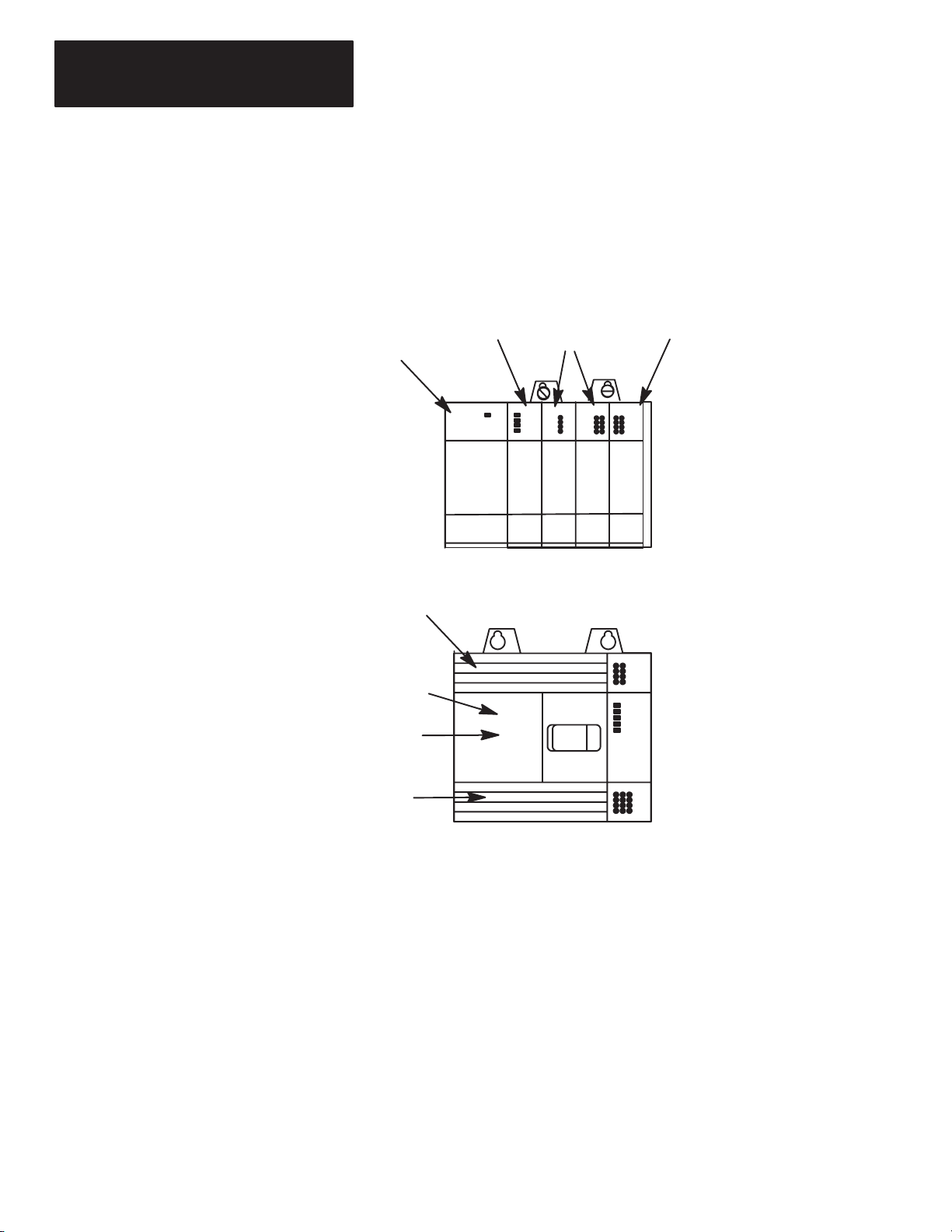
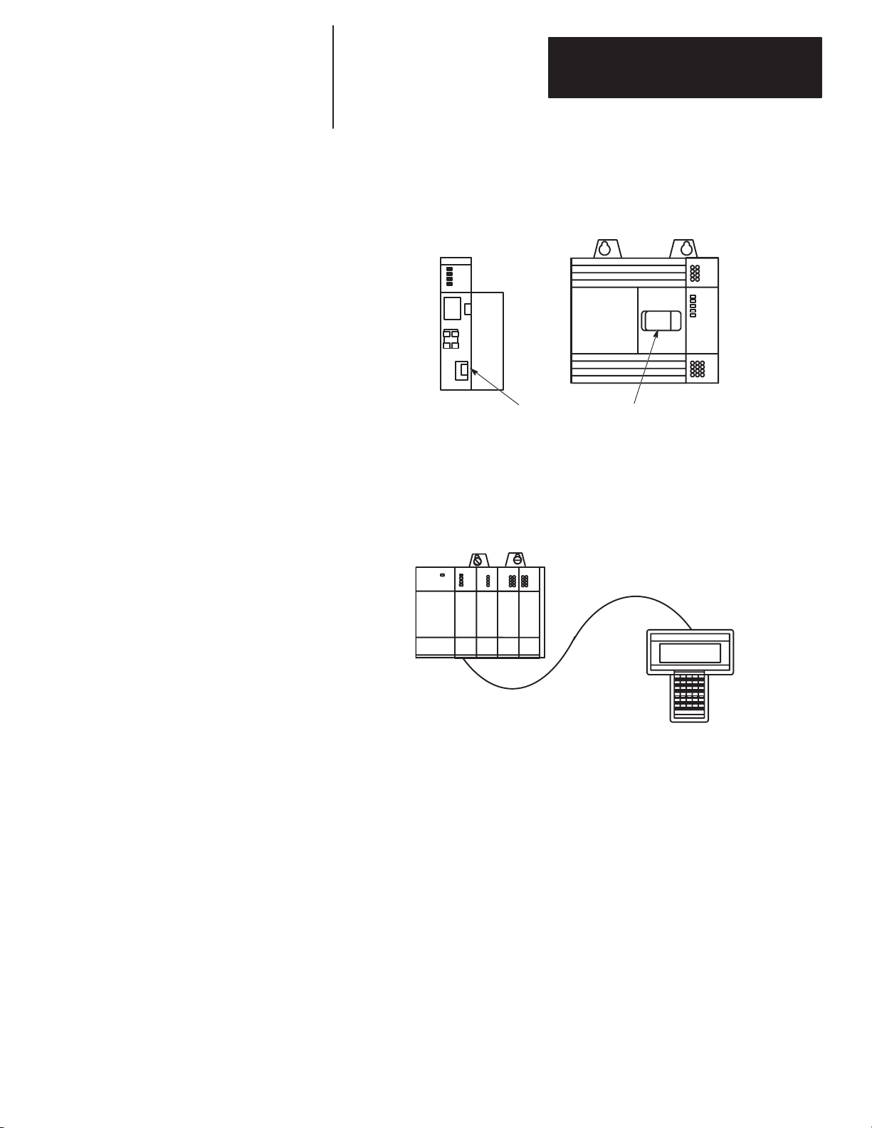
The SLC 500 comes in two different styles: modular and fixed. These styles
are shown below. The modular controller consists of a rack, power supply,
processor (CPU), and Input/Output (I/O) modules. The fixed controller
consists of a power supply, processor (CPU), and a fixed number of I/O
contained in a single unit. You can add an expansion rack to the fixed
controller.
Output Module
SLC 500 Modular Controller
Power Supply
Output Terminals
Processor
Input Modules
Slot 0 1 2
3
Power
Supply
Processor (CPU)
Input
Terminals
Slot 0
SLC 500 Fixed Controller
Further information on hardware is found in the Installation and Operation
Manuals, Publication 1747–800 (fixed controllers) and 1747–804 (modular
controllers).
1–2
Page 10
Getting Started Guide
for HHT
Chapter 1
Setting Up Your Equipment
Setting Up a Demo Unit
SLC 500 Modular Controller
SLC 500 demo units are available with either a fixed controller or modular
controller. This guide assumes you are using a modular controller demo unit
for all the programming exercises. If you use a fixed controller demo unit,
you will need to use different configuration information and I/O addresses in
the exercises. This is explained later.
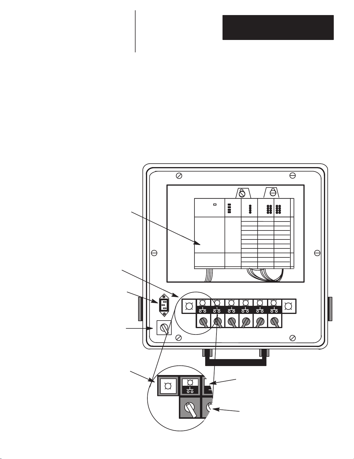
The figure below shows an SLC 500 modular controller demo unit. It is
completely wired, with 12 external inputs (6 push buttons and 6 selector
switches) and 8 external outputs (pilot lights).
Note the On/Off Power Switch and the Power Supply Receptacle on the
demo. Make certain that the power switch is Off, then insert one end of the
power cord into the power supply receptacle and the other end into an
electrical socket.
Input/Output
Panel
Power Supply
Receptacle
On/Off Power
Switch
Pilot Light
102
60
0
6
O
O
F
N
F
O
6
O
N
F
F
Combination
Pilot Light/Pushbuttons
Selector Switches
1–3
Page 11

Chapter 1
Setting Up Your Equipment
Setting Up a Field–Wired
Controller
Installing the Memory Pak, Battery, and Communication Cable
The details of installing and wiring the controller and external input/output
devices are beyond the scope of this guide.
If you are using a field–wired fixed or modular controller, refer to the
Installation and Operation Manuals, Publication 1747–800 (fixed controllers)
and 1747–804 (modular controllers), for information on installation and
wiring of the controller and external input/output devices.
We recommend that your controller have two external input circuits and two
external output circuits to complete the exercises in this guide.
The HHT (with communication cable), the memory pak, and the battery are
supplied separately. Install the memory pak, battery, and communication
cable as follows:
1. Install the memory pak first. The English version is catalog number
1747–PTA1E.
Important: The memory pak contains CMOS devices. Wear a
grounding strap and use proper grounding procedures to
guard against damage to the memory pak from
electrostatic discharge.
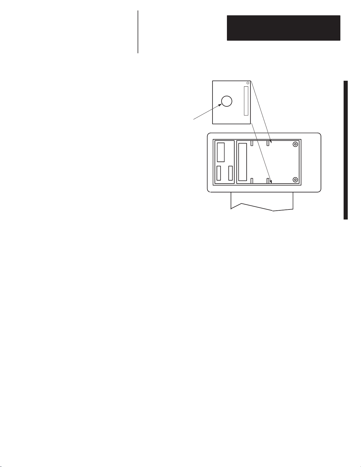
A. To install the memory pak, remove the cover from the back of the
HHT.
Backside
Slide cover to the left. Lift of
of HHT
f cover
.
1–4
Page 12
Getting Started Guide
for HHT
Chapter 1
Setting Up Your Equipment
B. Insert the memory pak in its compartment as indicated in the following
figure.
After the memory pak
is in the compartment,
press down on handle
to secure connector in
socket.
.
.
.
.
.
.
.
.
.
.
.
.
.
.
.
.
.
.
.
.
.
.
.
.
.
Backside of HHT
1–5
Page 13
Chapter 1
Setting Up Your Equipment
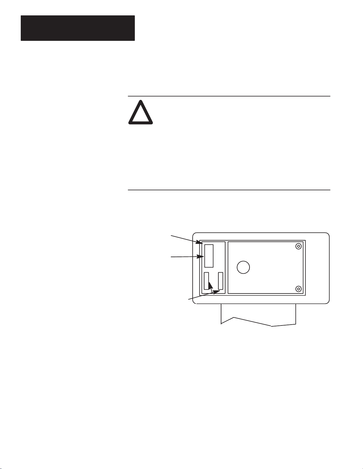
2. Install the battery, catalog number 1747–BA. The battery compartment is
next to the memory pak compartment.
ATTENTION: If you do not install a battery, the letter B
appears flashing on the prompt line of the HHT display to let you
!
know that battery power is low; in addition, each time you power
up, the self–test diagnostic will be interrupted, and the statement
BATTERY
TEST FAILED
will appear.
To prevent this from happening, leave the “battery low defeat
jumper” inserted in the battery socket. The HHT will be
functional, but your user program will be cleared form memory
when you de–energize the HHT. If you do not download the user
program to the processor before you de–energize the HHT, your
program will be lost.
A. Remove the jumper from the battery socket, then plug the battery
connector into the socket (red wire up). Secure the battery between
the clips.
Battery
Compartment
Plug battery connector into
socket (red wire up).
Secure battery between clips.
B. Replace the cover.
.
.
.
Backside of HHT
1–6
Page 14
Getting Started Guide
for HHT
Chapter 1
Setting Up Your Equipment
3. Locate the Communications Port of the controller. The figure below
shows where it is located on modular and fixed controllers.
Processor Module
(Modular Controller)
(cover open)
(Communication Port)
SLC 500 Fixed Controller
Connectors are keyed. Connect one end of the 1747–C10 communication
cable to the top of the HHT. The other connector plugs into the
communication port on the front of the fixed I/O controller, or into the
communication port on the front of the CPU module of modular controllers.
1747–C10 Cable
SLC Controller
(Modular)
HHT
If you are using a 1747–NP1 Wall–Mount power supply or a 1747–NP2
Global Desk Top power supply, plug the communication cable connector into
the socket provided.
1–7
Page 15
Chapter 1
Setting Up Your Equipment
HHT Features
Display Area
Use the Hand–Held Terminal to configure the SLC 500 controller,
enter/modify a user program, download/upload programs, monitor controller
operation, test, and troubleshoot. The HHT has its own memory to store a
program.
You can use the HHT stand alone (for remote programming development
with 1747–NP1 or NP2 power supply), point–to–point (one HHT to one
controller), or on a DH–485 network (communicate with up to 31 nodes over
4,000 feet). When equipped with a battery (1747–BA), the HHT will retain a
user program in memory for storage and later use.
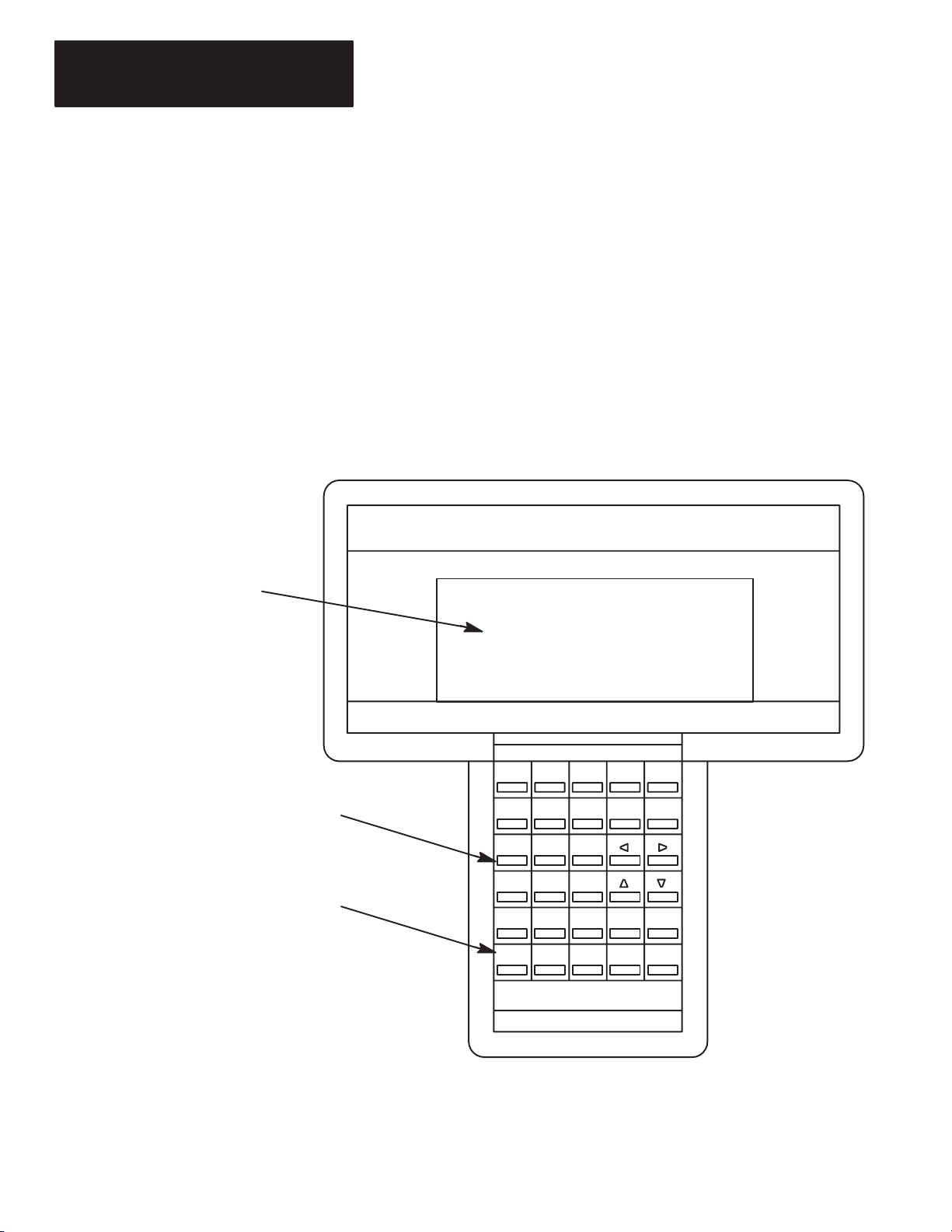
The HHT is menu–driven. The display area accommodates 8 lines x 40
characters. You can display five rungs of a user program. When monitoring
the program in the RUN mode, instructions in a ladder diagram are
intensified to indicate “true” status.
SLC 500 PROGRAMMING SOFTWARE Rel. 2.03
Allen–Bradley Company Copyright 1990
PRESS A FUNCTION KEY
SELFTEST TERM PROGMAINT UTILITY
All Rights Reserved
F1 F2 F3 F4 F5
1747 – PTA1E
OFL
1–8
Calculator–style,
color–coded keyboard
Keys operate with motion and
tactile response.
F1 F2
NO
ACC/POS
PRE/LEN
A
7
D
4
T
1
#0–
F3 F4 F5
S
I
U
B
C
8
9
E
F
5
6
R
M
2
3
.
:/
SPACE
SHIFT
ESC
ZOOMRUNG
Enter
Page 16
Getting Started Guide
for HHT
Chapter 1
Setting Up Your Equipment
HHT Powerup
HHT Display Format
After you install the memory pak and battery, and plug in the cable, you can
test operation of the HHT by powering up the controller (or plugging in the
Wall–Mount or Global Desk Top power supply).
When the HHT is energized, it will go through a series of diagnostic tests.
Then the following display is shown.
SLC 500 PROGRAMMING SOFTWARE Rel. 2.03
Allen–Bradley Company Copyright 1990
All Rights Reserved
PRESS A FUNCTION KEY
SELFTEST TERM PROGMAINT
F1 F2 F3 F4 F5
1747 – PTA1E
OFL
UTILITY
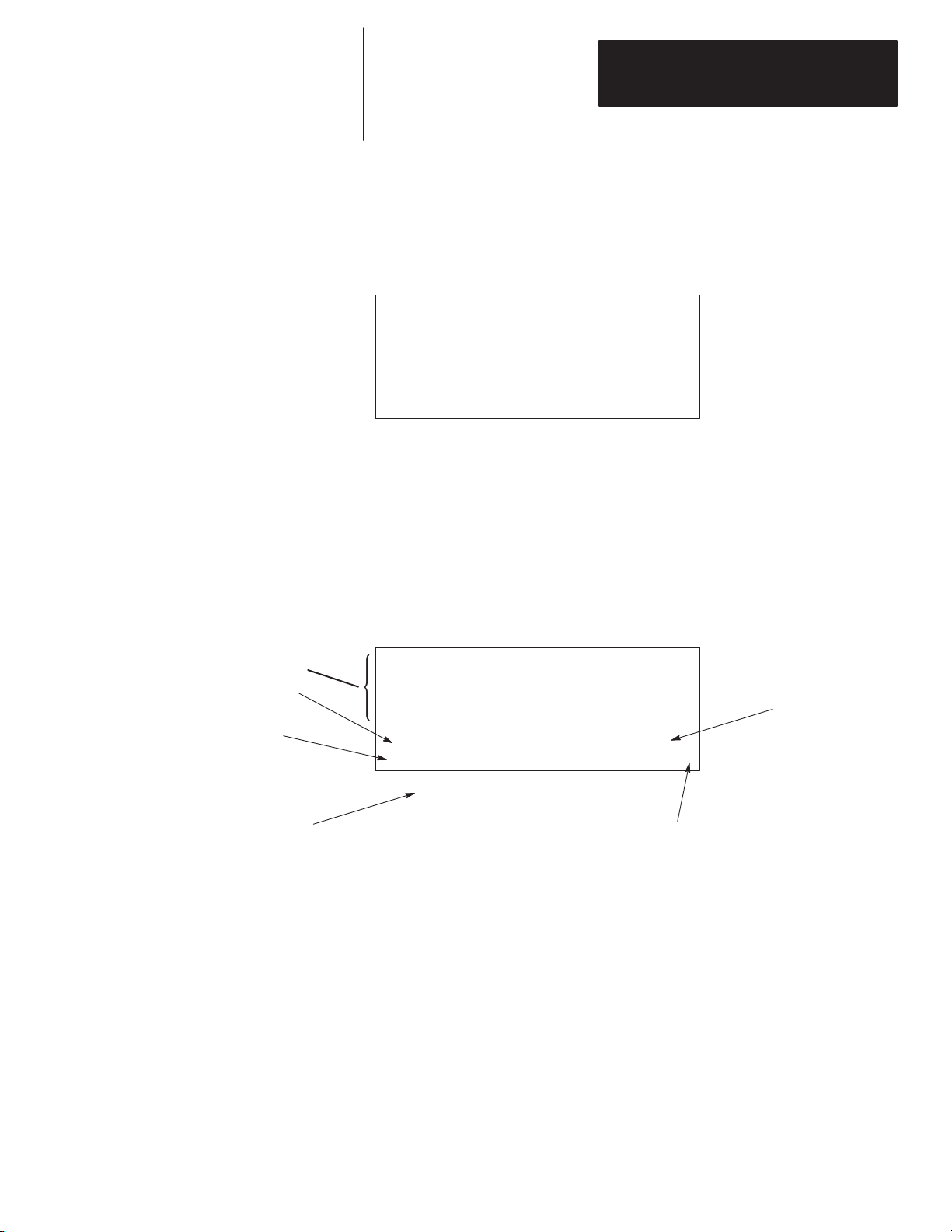
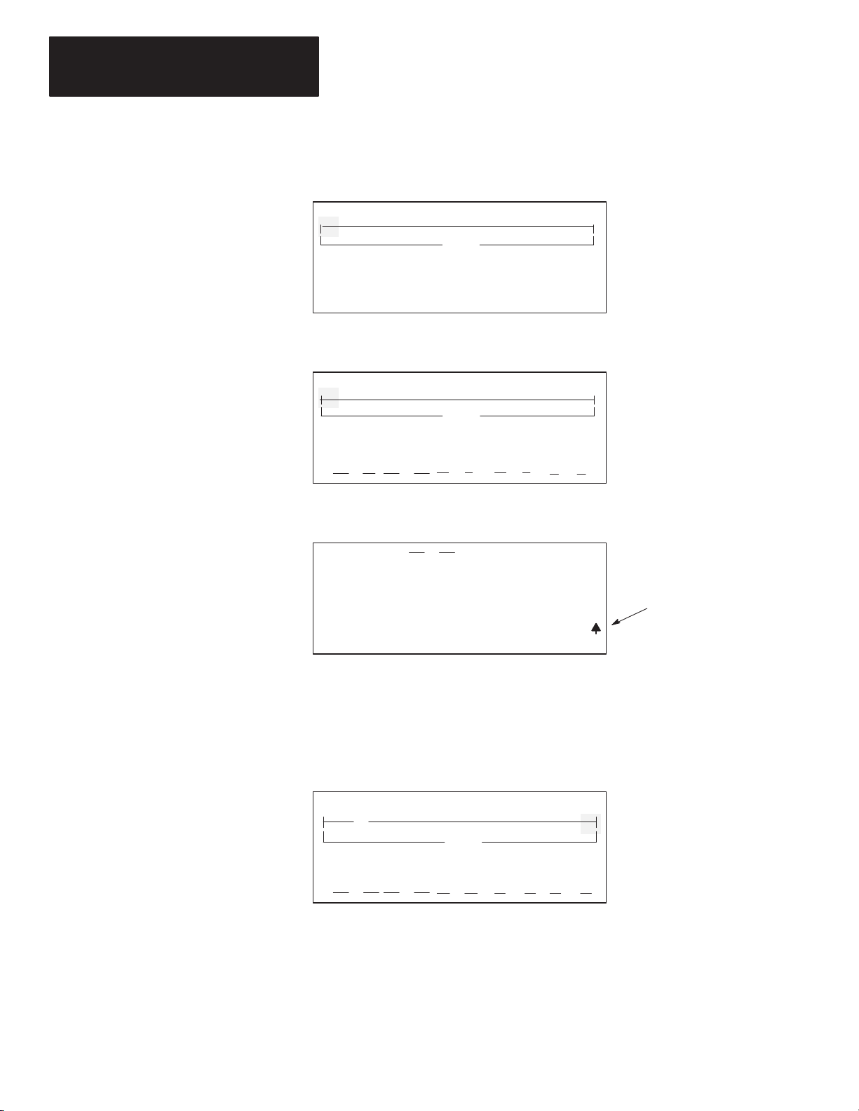
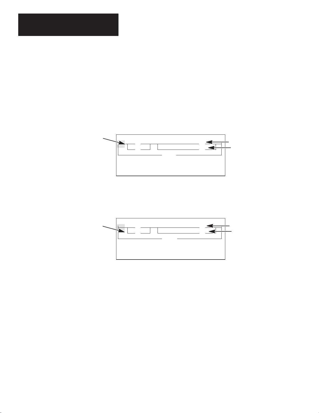
The HHT display format consists of the following:
• Display area
• Prompt/Data Entry/Error Message area
• Menu tree functions
The figure below indicates what appears in these areas. (To access this
[F3]
screen, press
– PROGMAINT
.)
Prompt/Entry/Error Area
Menu tree functions are
directly accessible.
Menu function keys are selected
[F1]
with
The Keyboard
to
[F5] keys.
Display Area
File Name: 101 Prog Name: 1492
File Name Type Size(Instr)
0 System *
1 Reserved *
2 101 Ladder
*
OFL
CHG_NAM CRT_FIL EDT_FIL DEL_FIL MEM_MAP >
F1 F2 F3 F4 F5
When the > symbol is present, pressing
[ENTER] will toggle additional menu functions.
Indicates that the HHT is offline.
This section is intended only as a brief preview of keyboard operation.
Beginning in chapter 3, you will become familiar with the keyboard as you
are guided through various programming procedures.
Menu Function Keys (F1, F2, F3, F4, F5)
The top row of purple keys, F1 through F5, are menu function keys. They
select the menu functions at the bottom of the screen. Note that when the >
symbol is present, the
any) at a particular menu level. The
previous menu level.
[ENTER] key will toggle additional menu functions (if
[ESC] key exits the display to the
1–9
Page 17

Chapter 1
Setting Up Your Equipment
A
B
Data Entry Keys (
C
7,
8,
9...)
These blue keys include numbers, letters, and symbols used for addresses,
password, file numbers, and other data. The data you enter always appears
on the prompt/data entry/error message area of the display.
In general, you obtain the upper character of a key by pressing the
[SHIFT]
key first. You do not have to hold it and press next key. Just press and
release
If you make an error while entering data, press
[SHIFT] and then press the next key.
[ESC]
and re–enter the data,
or use cursor keys and the space key. To complete a data entry, press
[ENTER]. You can also use the [ESC] key to exit the data entry and return to
the next higher (previous) menu level.
Auto Shift
When you enter an instruction address, the HHT automatically goes to
SHIFT mode. This mode is indicated by a small arrow in the bottom right
hand corner of the display.
ZOOM on XIC
NAME: EXAMINE IF CLOSED
BIT ADDR:
ENTER BIT ADDR:
F1 F2 F3 F4 F5
] [
2.0.0.0.*
Indicates that the HHT is in
SHIFT mode (e.g., to enter
the letter “I” you do not
have to first select SHIFT).
1–10
Cursor Keys
,,,
Use these four green, arrow keys to:
• Correct data entry errors (either type over or use space key).
• Move the cursor left, right, up, and down in a ladder program. Rungs not
shown in the HHT display will automatically scroll into view as you
cursor down (or up) in the program.
• Scroll through controller and I/O configuration selections.
• Scroll through program file directories.
• Scroll through the elements and bits of individual data files.
ZOOM and RUNG Keys
The [ZOOM] key brings up a display that shows the parameters of an
instruction (helpful with timers, counters, sequencers, etc.; also helpful
during editing).
[RUNG] key moves the cursor to a particular rung. Using the [RUNG] key
The
saves time when you have a long ladder diagram. When you press
you are prompted for the rung number that you want to edit or monitor. You
enter the rung number and press
[ENTER], then the cursor moves to the
selected rung and the rung appears at the top of the screen.
[RUNG],
Page 18

Getting Started Guide
for HHT
Chapter
A–B
2
Control Basics
This chapter introduces you to basic concepts essential for understanding
how the SLC 500 controller operates. It covers:
• SLC 500 file concepts
• How external I/O devices communicate with the processor
• Addressing external I/O
• External I/O addressing formats
• Ladder logic concepts
SLC 500 File Concepts
The CPU, or processor, provides control through the use of a program you
create. This program contains files that break down into more manageable
sections. These sections are:
• Program Files — provide storage and control of the main program and
subroutines.
• Data Files — contain the status of inputs, outputs, the processor, timers,
counters, and so on.
Notes on terminology: The term program used in Hand–Held Terminal
(HHT) displays and documentation is equivalent to the term processor file
used in APS software displays and documentation. Both terms mean the
collective program files and data files created under a particular program or
processor file name.
Program
The HHT and each CPU can hold one program at a time. The program is
made up of program files (up to 256 per controller) and data files (up to 256
per controller).
Program
Program Files
Data Files
A program is created in the offline mode using your HHT. It is then
downloaded to the processor for online operation.
2–1
Page 19

Chapter 2
Control Basics
Program Files
Program files contain controller information, the main control program, and
any subroutine programs. The first three program files are required for each
program. These are:
• File
0
This file stores the controller configuration and other system information.
• File
1
This file is reserved for internal controller use.
• File
2
This file stores the main control program.
• Files
Most of your work with program files will be in file 2, the main program file.
This file contains your ladder logic program that you create to control your
application.
3 – 255
These files are optional and used for subroutine programs.
Data Files
Data files contain the data associated with the program files. Each program
can contain up to 256 data files. These files are organized by the type of data
they contain. Each piece of data in each of these files has an address
associated with it that identifies it for use in the program file. For example,
an input point has an address that represents its location in the input data file.
Likewise, a timer in the timer data file has an address associated with it that
allows you to represent it in the program file.
The first 9 data files (0 – 8) have default types. You designate the remainder
of the files (9 – 255) . The default types are:
• File 0 – Output Data
This file stores the state of the output terminals for the controller.
• File
1 – Input Data
This file stores the status of the input terminals for the controller.
• File
2 – Status Data
This file stores controller operation information.
• Files
• File
• Files
3 – 7
These files are pre–defined as Bit, Timers, Counters, Control, and Integer
data storage, respectively.
8
This file is reserved for internal use.
9 – 255
These files are user–defined as Bit, Timer, Counters, Control, and Integer
data storage.
2–2
Most of your work with data files will be in files 0 and 1, the output and
input files. Refer to appendix A for an example of the Timer data file.
Page 20
Getting Started Guide
for HHT
Chapter 2
Control Basics
How External I/O Devices Communicate with the Processor
Input Module
in slot 1
F8
0
Pushbutton 0 is wired to terminal 0.
Pressing pushbutton 0 will cause
the corresponding status bit in the
input data file to go from 0 to 1.
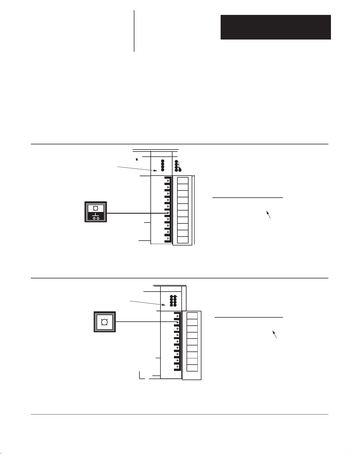
The figure below applies to a modular controller demo unit having an input
module in slot 1 and an output module in slot 3. See page 1–2 for a diagram
of the slot location. To simplify the illustration, only pushbutton 0 and pilot
light 0 of the external I/O are shown.
Each of the external input circuits is represented by a status bit in the input
data file of the program. Each of the external output circuits is represented
by a status bit in the output data file of the program. During controller
operation, the processor applies the input data to the program, solves the
program based on the instruction you enter, and energizes and de–energizes
external outputs.
SLC 5/01 CPU
INPUT
INPUT
INPUT
IN 0
IN 1
IN 2
IN 3
Input Data File
address data
I:1 0000
Status bit 0
corresponds to
terminal 0 of the
input module in
slot 1.
Closing an external input circuit changes the corresponding status bit from 0 to 1.
Opening an external input circuit changes the corresponding status bit from 1 to 0.
Output Module
in slot 3
0
Pilot light 0 is wired to terminal 0.
The pilot light will be energized
when the processor has completed
evaluation of the program and
transfers the ON/OFF status to
the outputs.
When an output data file status bit has been solved as a 1, the corresponding external output circuit will
be energized (ON).
When an output data file status bit has been solved as a 0, the corresponding external output circuit is
de–energized (OFF).
OUTPUT
OUT
OUT 1
OUT 2
OUT 3
OUT 4
OUT 5
OUT 6
OUT 7
Output Data File
address data
0
O:3 0000 0000
Status bit 0
corresponds to
terminal 0 of the
output module in
slot 3.
2–3
Page 21

Chapter 2
Control Basics
Addressing External I/O
As pointed out in the last section, external inputs and outputs are linked to
the input data file and output data file of the program. Each status bit in
these files has an address. You specify the appropriate address when you
enter an instruction in your ladder program.
For our purposes, input addresses have the form I:e/b
where
= Input data file
I
:
= Element or slot delimiter
= Slot number of the input module
e
= Bit or terminal delimiter
/
b
= Terminal number used with input device
Similarly, output addresses have the form
O:e/b
where
O
= Output data file
:
= Element or slot delimiter
= Slot number of the output module
e
/
= Bit or terminal delimiter
= Terminal number used with output device
b
Examples:
I:1/0
= Input, slot 1, terminal 0
I:2/0 = Input, slot 2, terminal 0
O:3/0 = Output, slot 3, terminal 0
O:3/7 = Output, slot 3, terminal 7
O:0/7 = Output, slot 0, terminal 7 (fixed controllers only because of slot 0)
I:0/4 = Input, slot 0, terminal 4 (fixed controllers only because of slot 0)
Eventually, you will be addressing other data files, such as Status, Bit, Timer,
Counter, Integer, and Control. Addressing of these files is discussed in the
HHT User Manual.
2–4
Page 22
Getting Started Guide
for HHT
Chapter 2
Control Basics
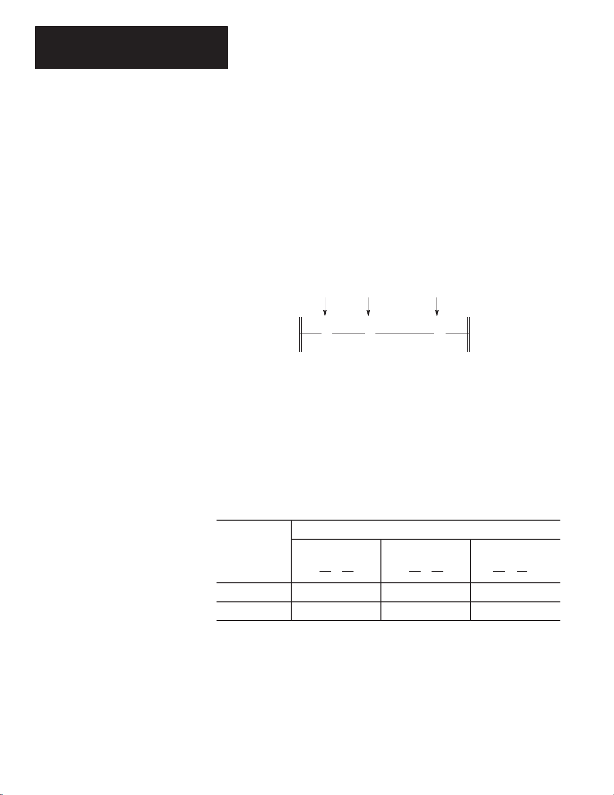
External I/O Addressing Formats
There are three ways in which an external I/O address appears in this guide:
• The five keyboard entries you make to enter the address in the HHT:
Delimiter Delimiter
O:2/7
Output Data File Slot 2 Terminal 7
• The full address, as it appears in the HHT displays:
Word 0Data File 0
O0:2.0/7
Output Data File Slot 2 Terminal 7
• The convention we use to show the address in the ladder diagrams:
Word 0Slot 2Output Data File
Your programming device displays the full address.
For example, when you assign the address O:3/0,
the programming device will show it as O0:3.0/0
(output file, file 0, slot 3, word 0, terminal 0).
O:2.0
( )
7
Terminal 7
HHT Display of Instructions/Addresses
The HHT displays I/O addresses as shown below.
When you locate the cursor on an instruction (as
shown below), the HHT displays the instruction
address in the upper left corner of the display.
NO FORCEOTE:O0:3.0/0
] [
<END>
INS_RNG MOD_RNG SEARCH DEL_RNG UND_RNG
F1 F2 F3 F4 F5
These numbers provide you with the following ladder program information:
2.0.0.0.2
( )
OFL
file number
rung number
nest level
branch level
instruction number (An asterisk
(*) means the cursor is not on
an instruction.)
>
2–5
Page 23
Chapter 2
Control Basics
Ladder Logic Concepts
As we mentioned earlier, the program files you create contain the program
used for your controlling application. The programs are written in a
programming language called Ladder Logic. This name is derived from its
ladder–like appearance.
A ladder logic program consists of a number of rungs, on which you place
instructions. Instructions each have a data address associated with them and
based on the status of these instructions the rung is solved.
The figure below shows a simple 1–rung ladder program. The rung includes
two input instructions and an output instruction. Note, in the example below
each instruction has a name (Examine if Closed), a mnemonic (XIC), and an
address (I:1/0).
Input Instructions Output Instruction
XIC
I:1.0
] [
0
XIC = Examine if Closed
XIO = Examine if Open
OTE = Output Energize
A simple rung, using bit instructions.
XIO OTE
I:1.0
]/[
1
O:3.0
Address I:1/0
Address I:1/1
Address O:3/0
( )
0
True/False Status
The data file bits that these instructions are addressed to will be either a logic
0 (OFF) or a logic 1 (ON). This determines whether the instruction is
regarded as “true” or “false”:
The status of the instruction is
If the data file
bit is
Logic 0 False True False
Logic 1 True False True
XIC
Examine if Closed
] [
XIO
Examine if Open
]/[
OTE
Output Energize
( )
2–6
Page 24

Getting Started Guide
for HHT
Chapter 2
Control Basics
Logical Continuity
During controller operation, the processor evaluates each rung, changing the
status of instructions according to the logical continuity of rungs. More
specifically, input instructions set up the conditions under which the
processor will make an output instruction true or false. These conditions are:
• When the processor finds a continuous path of true input instructions in a
rung, the OTE output instruction will become (or remain) true. We then
say that “rung conditions are true.”
• When the processor does not find a continuous path of true input
instructions in a rung, the OTE output instruction will become (or remain)
false. We then say that “rung conditions are false.”
The figure below indicates the data file conditions under which the rung is
true:
Input Instructions Output Instruction
XIC
I:1.0
] [
0
Input Data File
address data
I:1 0001
Status bit I:1/1 is a
logic 0, making the
XIO instruction true.
Status bit I:1/0 is a
logic 1, making the
XIC instruction true.
In the above example, if the input data file was 0000, then the rung would be
false and the output data file would read as 0000 0000.
XIO OTE
I:1.0
]/[
1
O:3.0
address data
O:3 0000 0001
The processor changes status bit O:3/0 to
a logic 1, because a continuous path of
true input instructions exist in the rung.
( )
0
Output Data File
2–7
Page 25
Chapter 2
Control Basics
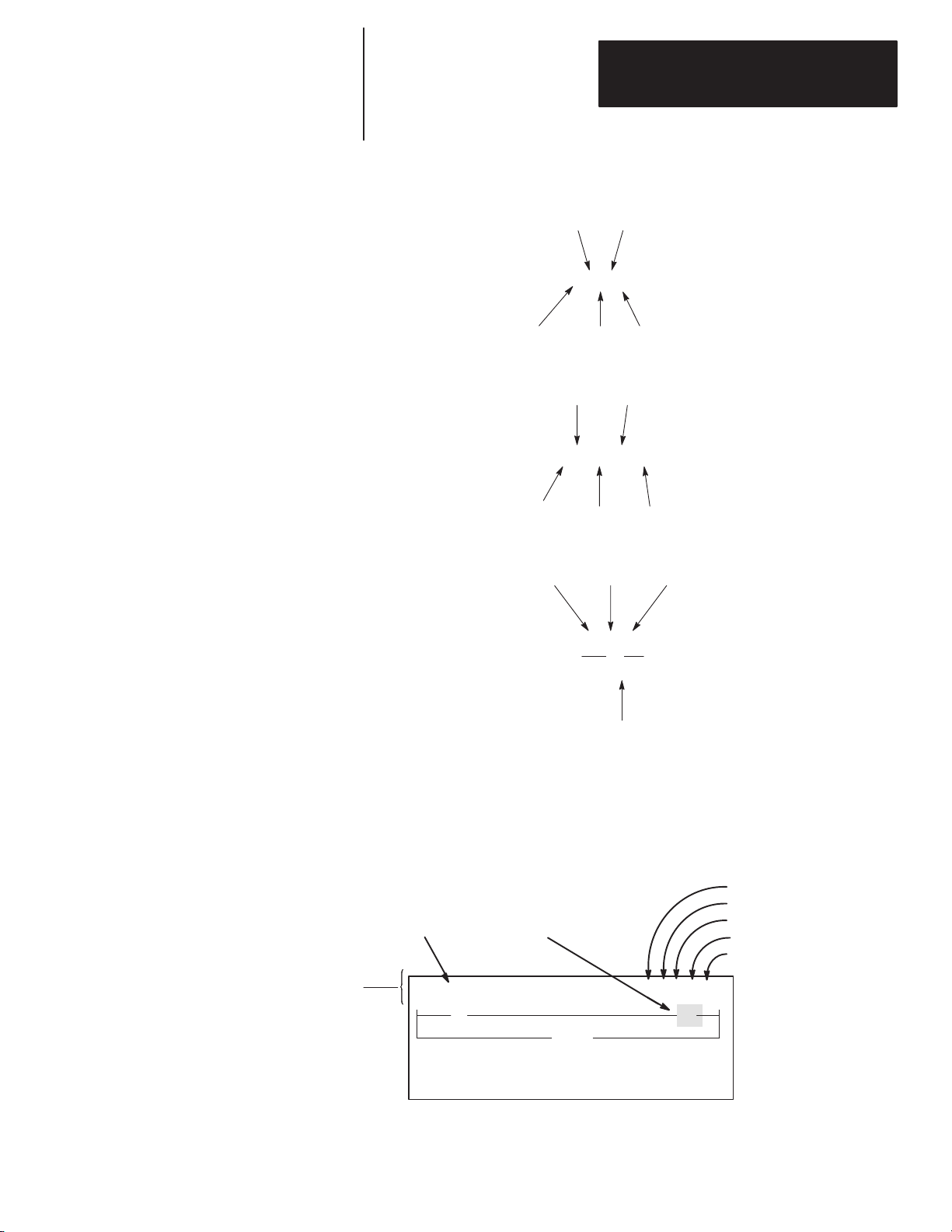
Processor Operating Cycle
The diagram below indicates the events that occur during the processor
operating cycle. This sequence is repeated many times each second.
Event Description
Input
Scan
Program Scan
Output Scan
Communications
Housekeeping
F8
0
activated
address data
O:3 0000 0001
1
I:1.0
] [
0
Output Data File
address data
I:1 0001
I:1.0
]/[
1
Input Data File
O:3.0
( )
0
0
Illuminated
Processor internal housekeeping takes place.
The status of external input circuits is
read. The input data file is updated with
this information.
The ladder program is executed. The
input data file is evaluated, the ladder
rung is solved, and the output data file
is updated.
The output data file information is
transferred to the external output circuit,
thus energizing or de–energizing it.
Communications with the HHT and other
network devices takes place.
2–8
Page 26

Getting Started Guide
for HHT
Chapter
A–B
3
Creating a Program
In this chapter you create a program. The tasks you will perform:
• For modular controllers: Make a record of the processor module catalog
number, the rack catalog number(s), the I/O module catalog numbers, and
the slot locations of I/O modules.
For fixed controllers: Make a record of the controller catalog number
(and I/O module catalog numbers and slot locations if you are using the
1746–A2 expansion rack).
• Use the HHT to create a program.
• Clear the HHT memory.
• Name the program “1000.”
• Enter the controller configuration.
• Enter a 1–rung ladder program.
• Save the program.
Configuration of SLC 500 Controllers
To make the best use of this guide, you should have access to an SLC 500
Demonstration Unit, which includes completely wired external inputs and
outputs. For the exercises in this guide, we assume that you are using a
Demo unit using a modular controller with the components listed on page
3–4.
3–1
Page 27

Chapter 3
Creating a Program
Controller Styles
As previously mentioned, SLC 500 controllers are available in two styles —
the fixed controller and the modular controller. Examples are shown in the
figure below.
Processor & Power Supply
Expansion Rack
Power Supply
SLC 500 Modular ControllerSLC 500 Fixed Controller
Processor
7–slot rack
12Slot 0
Slot 0 1 2 3 4 5 6
The fixed controller combines a power supply, processor (CPU), and a fixed
number of I/O points in a single unit. You have the option of adding a 2–slot
expansion rack if you want to add I/O points.
The modular controller consists of a power supply, 1–3 I/O racks, a processor
module that you insert in slot 0 of the first rack, and various I/O modules that
you insert in the remaining slots of the racks.
Slot Numbers: Note that slot numbers are indicated in the figure above. In
fixed controllers, slot 0 applies to the processor and fixed I/O points; slots 1
and 2 apply to I/O modules located in the expansion rack. In modular
controllers, slot 0 is always reserved for your processor module; the
remaining slots apply to the various I/O modules you have inserted.
Catalog Numbers
When you configure your controller, you must specify the processor catalog
number, rack catalog numbers, and I/O module catalog numbers as required.
The location of the catalog number on the various components is shown in
the following figures.
3–2
Make a record of controller components: We recommend that you make a
list of the processor, rack, and I/O catalog numbers, and also the rack
numbers assigned to the racks and the slot locations of all I/O modules. You
can then refer to this list as you configure your controller.
Page 28

Getting Started Guide
for HHT
Chapter 3
Creating a Program
Catalog Number Location – SLC 500 Fixed Controllers
Label for Processor Catalog
and Serial Number
SLC
500
CAT
1747–L _ _ _
Processor
Catalog Number
The catalog number for the
expansion rack is 1746–A2. It
appears on side of the rack.
Side View
Catalog Number Location – SLC 500 Modular Controllers
Processor (CPU) Modules
Label for Processor Catalog
and Serial Number
Side View
Racks
SLC
500
CAT
1747–L _ _ _
Processor
Catalog Number
Label for Rack Catalog
and Serial Number
SLC
500
CAT
1746–_ _ _
Rack Catalog Number
I/O Modules
Catalog Number
1746–_ _ _
The catalog number and
serial number for I/O
modules also appears on
the side of the module.
Side View
3–3
Page 29

Chapter 3
Creating a Program
Arbitrary Controller Used in this Guide
In the following procedures, we have assumed that the controller you are
configuring in your program is a modular demo unit including the following
components:
• Rack 1746–A4, 4–slot rack
• Processor 1747–L511 in slot 0
• Input module 1746–IA4 in slot 1
• Input module 1746–IA8 in slot 2
• Output module 1746–OA8 in slot 3
The ladder program shown on page 3–11 contains I/O addresses that are
consistent with the configuration indicated above. If you are using some
other controller configuration, keep in mind that these addresses may not be
valid for your controller.
Creating a Program
A program is always created offline. In creating the program, you will:
• Clear the memory of the HHT.
• Name the program and configure the controller.
• Enter a ladder program.
• Save the program in the HHT.
The abbreviated function keys that you will be encountering, both in this
Guide and on the HHT display, are explained in appendix C.
3–4
Page 30

Getting Started Guide
for HHT
Chapter 3
Creating a Program
Clearing the Memory of the HHT
To create a new program, you must clear the HHT memory (DEFAULT
program).
1. Energize your HHT. After the HHT goes through self–diagnostic tests,
the following display appears
SLC 500 PROGRAMMING SOFTWARE Rel. 2.03
:
Allen–Bradley Company Copyright 1990
All Rights Reserved
PRESS A FUNCTION KEY
SELFTEST TERM PROGMAINT
F1 F2 F3 F4 F5
2. Press [F3]
1747 – PTA1E
– PROGMAINT
OFL
UTILITY
. Either the following display appears (if a
program is in the HHT), or. . .
File Name: Prog Name:2345
File Name Type Size(Instr)
0 System 76
1 Reserved 0
2 Ladder 5
CHG_NAM CRT_FIL EDT_FIL
F1 F2 F3 F4 F5
DEL_FIL
OFL
>
MEM_MAP
this display appears (if a program is not in the HHT).
File Name: Prog Name:DEFAULT
File Name Type Size(Instr)
0 System *
1 Reserved *
2 Ladder *
2345 (or anything other
than DEFAULT) indicates
that a program is in the HHT.
DEFAULT indicates that a
program is not in the HHT.
CHG_NAM CRT_FIL EDT_FIL
F1 F2 F3 F4 F5
DEL_FIL
OFL
>
MEM_MAP
Clear the memory as follows, even if the DEFAULT program is present.
3. Press
4. Press
5. Press [F2]
[ENTER]. More menu options appear.
[F4]
– CLR_MEM
File Name: Prog Name:2345
File Name Type Size(Instr)
0 System 76
1 Reserved 0
2 Ladder 5
ARE YOU SURE?
YES
F1 F2 F3 F4 F5
– YES
. The following display appears
NO
OFL
. This clears the HHT memory. Now you are ready to
create a program.
3–5
Page 31

Chapter 3
Creating a Program
Naming the Program and Configuring the Controller
The following indicates how to name your program and configure your
controller using the HHT.
Naming Your Program
1. Press
2. Press
3. Press
[ENTER] to view more options.
[F1]
– CHG_NAM
[F2]
– PROGRAM
––––––– Change Program/File Name–––––––
File Name:
Program Name: DEFAULT
ENTER NAME: DEFAULT
F1 F2 F3 F4 F5
.
. The following display appears:
OFL
4. Name your program “1000.” (Press [1][0][0][0][SPACE][ENTER].)
The program name is entered.
5. Exit this menu level by pressing
File Name: Prog Name:1000
File Name Type Size(Instr)
0 System *
1 Reserved *
2 Ladder *
CHG_NAM CRT_FIl EDT_FIL
F1 F2 F3 F4 F5
[ESC]. The following display appears:
Program Name
OFL
DEL_FIL >MEM_MAP
3–6
The program directory now shows the name of the program, which is 1000.
Page 32

Getting Started Guide
for HHT
Chapter 3
Creating a Program
Configuring the Processor
1. Press
[ENTER] to view the additional menu functions (as indicated by the
> symbol in the lower right corner). The following display appears:
File Name: Prog Name:1000
File Name Type Size(Instr)
0 System *
1 Reserve *
2 Ladder *
EDT_DAT SEL_PRO EDT_I/O
F1 F2 F3 F4 F5
2. Press [F2]
Type = 1747–L511 CPU–1K USER MEMORY
Series =
Memory Size = 1 K INSTRUCTIONS
TYPE SERIES
F1 F2 F3 F4 F5
3. Press
Type = 1747–L511 CPU–1K USER MEMORY
Series =
Memory Size = 1 K INSTRUCTIONS
– SEL_PRO
[F1] – TYPE
. The following display appears:
CLR_MEM >
. The following display appears:
OFL
Type = 1747–L511 CPU–1K USER MEMORY
OTHER
F1 F2 F3 F4 F5
4. Use the cursor keys ([ ↑ ] or [ ↓ ]) and press [ENTER] to select the the right
processor type. (For our example, we want the
therefore, we just press
[ENTER]
). Processor module 1747–L511 is
1747–L511 type;
entered into memory.
5. Press
[ESC] to return to the following display:
File Name: Prog Name:1000
File Name Type Size(Instr)
0 System *
1 Reserved *
2 Ladder *
EDT_DAT SEL_PRO EDT_I/O
F1 F2 F3 F4 F5
CLR_MEM >
OFL
3–7
Page 33

Chapter 3
Creating a Program
Configuring Your I/O
[F3]
1. Press
Rack 1 = 1746–A4 4–SLOT RACK
Rack 2 = NONE
Rack 3 = NONE
Slot 0 = 1747–L511 CPU–1K USER MEMORY
Slot 1 = NONE
MOD_RCK MOD_SLT DEL_SLT UND_SLT
F1 F2 F3 F4 F5
– EDT I/O
. The following display appears:
The display shows that the processor module we just entered is assigned to
slot 0. It also shows the default rack selection
1746–A4. For our example we
do not have to change the rack selection. If you are using a different rack,
press
[F1] – MOD_RCK
using the up and down cursor keys, then press
, then [F1]
– RACK 1
. Select the appropriate rack,
[ENTER]. If you are using
more than one rack, follow the same procedure for racks 2 and 3.
The next task is to assign the I/O module slots. For our example, we use
slots 1, 2 and 3.
2. Press
Slot
3. Assign input module
[F2] – MOD_SLT
Rack 1 = 1746–A4 4–SLOT RACK
Rack 2 = NONE
Rack 3 = NONE
Slot 0 = 1747–L511 CPU–1K USER MEMORY
Slot 1 = NONE
Slot 1 = NONE
F1 F2 F3 F4 F5
1 = NONE
[↓ ] key. (For our example, we press the [ ↓ ] key once.) The following
appears on the prompt line.
. The following display appears:
OTHER
1746–IA4 to slot 1 by scrolling or jogging with the
screen appears:
Rack 1 = 1746–A4 4–SLOT RACK
Rack 2 = NONE
Rack 3 = NONE
Slot 0 = 1747–L511 CPU–1K USER MEMORY
Slot 1 = NONE
Slot 1 = 1746–IA4 4–INPUT 100/120 VAC
OTHER
F1 F2 F3 F4 F5
3–8
4. Press [ENTER]. 1746–IA4 is entered for slot 1.
5. Call up another slot number using the
[ ↓ ] and [ ↑ ] keys. Press the [ ↓ ]
key once.
Slot
2 = NONE
appears on the prompt line.
Page 34

Getting Started Guide
for HHT
Chapter 3
Creating a Program
6. Press [F2]
– MOD_SLT.
7. Assign 1746–IA8 in slot 2: press the [ ↓ ] key twice, then [ENTER]. The
following display appears:
Rack 1 = 1746–A4 4–SLOT RACK
Rack 2 = NONE
Rack 3 = NONE
Slot 0 = 1747–L511 CPU–1K USER MEMORY
Slot 2 = 1746–IA8 8–INPUT 100/120 VAC
MOD_RCK MOD_SLT DEL_SLT UND_SLT
F1 F2 F3 F4 F5
8. Call up slot 3 using the cursor key. Press the [ ↓ ] key once.
9. Press
10.Assign
[F2]
– MOD_SLT
Slot 3 = NONE
appears on the prompt line.
.
1746–OA8 in slot 3: press the [ ↓ ] seven times. Then press
[ENTER]. The following display appears:
Rack 1 = 1746–A4 4–SLOT RACK
Rack 2 = NONE
Rack 3 = NONE
Slot 0 = 1747–L511 CPU–1K USER MEMORY
Slot 3 = 1746–OA8 8–OUT(TRI) 100/240 VAC
MOD_RCK MOD_SLT DEL_SLT UND_SLT
F1 F2 F3 F4 F5
Your controller is now fully configured.
11. Press
[ESC]. This returns you to the display shown below.
File Name: Prog Name:1000
File Name Type Size(Instr)
0 System *
1 Reserved *
2 Ladder *
EDT_DAT SEL_PRO EDT_I/O
F1 F2 F3 F4 F5
CLR_MEM >
OFL
3–9
Page 35

Chapter 3
Creating a Program
Monitoring Your Data File
To verify that the output and input data files for the I/O modules have been
created, you can call up data files for the I/O.
1. Press
[F1]
– EDT_DAT
Address 15 data 0
O0:3.0 0000 0000
O0:3.0/0 = 0
ADDRESS NEXT_FL PREV_FL NEXT_PG PREV_PG
F1 F2 F3 F4 F5
. The following display appears:
OFL
8 bits
This is file 0, the output data file. It indicates that slot 3 of the controller has
8 bits assigned (representing outputs
O:3/0
through
O:3/7
). (For more
information, see the section concerning “Addressing External I/O” in
chapter 2.)
[F2]
2. Press
Address 15 data 0
I1:1.0 0000
I1:2.0 0000 0000
I1:1.0/0 = 0
ADDRESS NEXT_FL PREV_FL NEXT_PG PREV_PG
F1 F2 F3 F4 F5
– NEXT_FL
. The following display appears:
4 bits
8 bits
OFL
3–10
This is file 1, the input data file. It indicates that slot 1 of the controller has 4
bits assigned (representing inputs
bits assigned (representing inputs
3. Now press
[ESC]
, then [ENTER]. The following display appears. You
I:1/0 through I:1/3), and that slot 2 has 8
I:2/0
through I:2/7).
are now ready for the next section.
File Name: Prog Name:1000
File Name Type Size(Instr)
0 System *
1 Reserved *
2 Ladder *
CHG_NAM CRT_FIL EDT_FIL DEL_FIL MEM_MAP
F1 F2 F3 F4 F5
OFL
>
Page 36

Getting Started Guide
for HHT
Chapter 3
Creating a Program
Programming a Simple Ladder Rung
The following rung consists of an XIC input instruction and an OTE output
instruction. The addresses conform to the controller configuration indicated
in the “Arbitrary Controller” section of this chapter. If you have entered a
different controller configuration, make certain that the addr
esses ar
consistent with your configuration. It is also important that you have an
external input, such as a pushbutton, and an external output, such as a pilot
light, at the terminal addresses used. You will be using these external
devices in later chapters of this guide.
e
I:1.0
] [
0
O:3.0
( )
0
Entering a Rung
To enter the rung, do the following:
1. Begin where we ended on the previous page, at the program directory
display.
2. Press [F3]
File Name: Prog Name:1000
File Name Type Size(Instr)
0 System *
1 Reserved *
2 Ladder *
ENTER FILE NUMBER:
F1 F2 F3 F4 F5
– EDT_FIL
. The following display appears.
OFL
We want to edit file number 2, our main program file.
[2]
3. Press
[ENTER]
other rungs exist at this time. The numbers
. The display shows the END rung of a program. No
2.0.0.0.* appear in the
upper right corner of the display. This indicates that we are in File 2, and
the cursor is located on rung 0, branch 0.
2.0.0.0.*
<END>
INS_RNG MOD_RNG SEARCH DEL_RNG UND_RNG
F1 F2 F3 F4 F5
4. Press [F1]
INS_INST BRANCH MOD_INST ACP_RNG
F1 F2 F3 F4 F5
– INS_RNG
<END>
. The following display appears:
2.0.0.0.*
OFL
>
OFL
>
3–11
Page 37
Chapter 3
Creating a Program
Entering an “Examine if Closed” Instruction
[F1]
1. Press
BIT TMR/CNT I/O_MSG CPT/MTH
F1 F2 F3 F4 F5
– INS_INST
. The following display appears:
2.0.0.0.*
<END>
OFL
COMPARE
>
2. Press [F1]
] [
F1 F2 F3 F4 F5
3. Press [F1]
ZOOM on XIC
NAME: EXAMINE IF CLOSED
BIT ADDR:
ENTER BIT ADDR:
F1 F2 F3 F4 F5
4. At the ENTER
– BIT
—] [—
. The following display appears:
]/[
] [
BIT ADDR:
2.0.0.0.*
<END>
( )
( )
L
OFL
( )
U
>
. The following display appears:
2.0.0.0.*
prompt, type the address I:1/0, then [ENTER].
(If you entered the wrong instruction by mistake, just press
again.)
5. Press
[F5]
– ACCEPT
. This accepts the address. The following display
appears:
Note that the HHT
“shifts” for you.
[ESC] and try
3–12
] [
<END>
] [
F1 F2 F3 F4 F5
]/[
( )
2.0.0.0.*
OFL
( ) ( )
>L
U
Page 38

Getting Started Guide
for HHT
Chapter 3
Creating a Program
Entering an “Output Energize” Instruction
1. Press
[F3], for the output energize instruction. The following display
appears:
ZOOM on OTE
NAME: OUTPUT ENERGIZE
BIT ADDR:
ENTER BIT ADDR:
F1 F2 F3 F4 F5
( )
2.0.0.0.*
2. Type bit address O:3/0, then [ENTER]. (If you entered the wrong
instruction by mistake, just press
[F5]
3. Press
[F5]
] [
INS_RNG MOD_RNG SEARCH DEL_RNG UND_RNG
F1 F2 F3 F4 F5
– ACCEPT
– ACP_ RNG
, then press [ESC] twice. Then press
. The following display appears:
<END>
[ESC]
2.1.0.0.*
and try again.)
( )
OFL
>
At this point the rung is entered and accepted.
4. Press
[ENTER] to display more menu options.
3–13
Page 39

Chapter 3
Creating a Program
Saving Your Program
Save your program at the end of a program edit. First your program is
compiled, transforming it into a more efficient package. Then the program is
saved from the work area into another part of memory. In addition, the
contents of program files and data files are updated. Also, a summary of data
words used, instructions used, and available memory is updated.
1. Start with the screen below, where we left off in the last section.
2.1.0.0.*
] [
<END>
EDT_DAT SAVE_CT SAVE_EX
F1 F2 F3 F4 F5
( )
OFL
>
2. Press [F5]
Future Access: Yes
MODIFY OPTIONS, ACCEPT TO COMPILE
FUTACC ACCEPT
F1 F2 F3 F4 F5
– SAVE_EX
Compiler Options
. The following display appears:
OFL
FUTACC (Future Access): This option lets you protect proprietary
program data and algorithms. The protection becomes operational only
after the program is downloaded to the controller. The “Future Access:
No” selection disallows online access to the processor unless a matching
copy of the online program is resident in the HHT.
Important: Do not select “Future Access: No” for this exercise.
3. Press [F5]
– ACCEPT
. This compiles and saves the program. After short
time, the following display appears:
File Name: Prog Name:1000
File Name Type Size(Instr)
0 System 76
1 Reserved 0
2 Ladder 3
3–14
CHG_NAM CRT_FIL EDT_FIL
F1 F2 F3 F4 F5
DEL_FIL >MEM_MAP
4. Return to the main display by pressing
OFL
[ESC]
.
Page 40

Getting Started Guide
for HHT
Chapter
A–B
4
Online Operations
In this chapter, you will complete the following tasks:
• Download program 1000, created in chapter 3.
• Test the program.
• Monitor the input and output data files.
4–1
Page 41

Chapter 4
Online Operations
Downloading Your Program
This chapter shows you how to download a program from the HHT to the
processor, then monitor the program. It assumes that you have performed the
tasks in chapter 3, and that the HHT shows the following display.
SLC 500 PROGRAMMING SOFTWARE Rel. 2.03
Allen–Bradley Company Copyright 1990
PRESS A FUNCTION KEY
SELFTEST TERM PROGMAINT
F1 F2 F3 F4 F5
1747 – PTA1E
All Rights Reserved
OFL
UTILITY
Going Online
1. Press [F5]
File Name: Prog Name:1000
File Name Type Size(Instr)
0 System 76
1 Reserved 0
2 Ladder 3
ONLINE WHO PASSWRD
F1 F2 F3 F4 F5
– UTILITY
. The following display appears:
OFL
CLR_MEM
2. Press
3. Press
[F2] – WHO
[F3]
– ATTACH
.
.
Either the following display appears (if a program is not in processor
memory), or. . .
Programmer Processor
Prog: 1000 Prog: DEFAULT
File: File:
Exec Files: 3 Exec Files: 3
Data Files: 9 Data Files: 3
DEFAULT FILE IN PROCESSOR
F1 F2 F3 F4 F5
Program Directory
DWNLOADOFFLINE CLR_PRC
MEM_PRC
PRG
this display appears (if a program is in processor memory).
Programmer Processor
Prog: 1000 Prog: 2345
File: File:
Exec Files: 3 Exec Files: 3
Data Files: 9 Data Files: 9
PROGRAM FILES DIFFER
F1 F2 F3 F4 F5
Program Directory
DWNLOADOFFLINE MODEUPLOAD
PRG
CLR_PRC
Important: If the above display appears and the processor is not
in program mode, then you must change the processor
[F4]
mode. To do this, press
[F5]
– PROGRAM
, then [F2]
– MODE
– YES
, then
, and then [ESC].
4–2
Page 42

Getting Started Guide
for HHT
Chapter 4
Online Operations
Downloading Your Program
1. Press DWNLOAD. The following display appears:
Programmer Processor
Prog: 1000 Prog: DEFAULT
File: File:
Exec Files: 3 Exec Files: 3
Data Files: 9 Data Files: 3
DOWNLOAD TO PROCESSOR?
F1 F2 F3 F4 F5
2. Press [F2]
Program Directory
YES
– YES
. This verifies that you want to download the file to the
NO
PRG
processor. For a brief moment, the following message should appear
DOWNLOADING
File Name: Prog Name:1000
File Name Type Size(Instr)
0 System 76
1 Reserved 0
2 Ladder 3
F1 F2 F3 F4 F5
FILE.
The following display appears:
PRG
MODEDWNLOADUPLOADOFFLINE
CLR_PRC
>
Changing Program Mode to Run Mode
1. Press [F4]
– MODE
. The following display appears:
File Name: Prog Name:1000
File Name Type Size(Instr)
0 System 76
1 Reserved 0
2 Ladder 3
PRG
TESTRUN
F1 F2 F3 F4 F5
2. Press [F1]
File Name: Prog Name:1000
File Name Type Size(Instr)
0 System 76
1 Reserved 0
2 Ladder 3
ARE YOU SURE?
F1 F2 F3 F4 F5
– RUN
. The following display appears:
PROGRAM
NOYES
PRG
4–3
Page 43

Chapter 4
Online Operations
3. Press [F2]
File Name: Prog Name:1000
File Name Type Size(Instr)
0 System 76
1 Reserved 0
2 Ladder 3
F1 F2 F3 F4 F5
– YES
. The following display appears again:
RUN
TESTRUN
PROGRAM
Monitoring the Program in Run Mode
1. Press [ESC], then [ENTER]. The following display appears:
File Name: Prog Name:1000
File Name Type Size(Instr)
0 System 76
1 Reserved 0
2 Ladder 3
RUN
EDT_DATXFERMEMPASSWRD
F1 F2 F3 F4 F5
MONITOR
>
2. Press [F5]
File Name: Prog Name:1000
File Name Type Size(Instr)
0 System 76
1 Reserved 0
2 Ladder 3
ENTER FILE NUMBER: RUN
F1 F2 F3 F4 F5
– MONITOR
. The following display appears:
3 . Press 2, then [ENTER]. The following display appears:
2.0.0.0.*
] [
<END>
MODE EDT_DAT SEARCH
F1 F2 F3 F4 F5
FORCE
( )
RUN
4–4
Page 44

Getting Started Guide
for HHT
Chapter 4
Online Operations
Testing Your Downloaded Program
The following diagram shows the rung you entered if you are using the
modular controller demo unit discussed in chapter 3. If you are using some
other controller configuration, make certain that your external input device
and output device are wired to the controller input and output that you
addressed in your ladder program.
1
F8
0
Address I:1.0/0 corresponds
to pushbutton 0 of the demo
unit.
I:1.0
] [
0
END
<>
Address O:3.0/0
corresponds to pilot light 0
of the demo unit.
0
O:3.0
( )
0
To test the program, press pushbutton 0. Pilot light 0 should go on. The
display should show both the XIC and OTE instructions highlighted to
indicate that they are true.
Processor operation: When you pressed pushbutton 0, the input instruction
went from false to true. This resulted in a path of true input instructions in
the rung, causing the output instruction to go from false to true.
Monitoring Data Files
Now, release the pushbutton. Pilot light 0 should go off. Neither instruction
in the rung should be highlighted. When you released pushbutton 0, the
input instruction went from true to false; this broke the path of true input
instructions, causing the output instruction to go from true to false.
In this procedure, you will monitor the input data file and the output data file.
These files include a status bit for each of the configured I/O terminals of the
controller. You will monitor data file changes as you operate pushbutton 0.
To end the exercise, you will go offline.
1. Beginning with the display shown on the previous page, press
[F3]
– EDT_DAT
Address 15 data 0
O0:3.0 0000 0000
O0:3.0/0 = 0
ADDRESS NEXT_FL PREV_FL NEXT_PG PREV_PG
F1 F2 F3 F4 F5
. The following display appears:
RUN
4–5
Page 45

Chapter 4
Online Operations
2. Monitor output data changes resulting from input device operation. Press
pushbutton 0. Note that the status bit corresponding with output
O:3/0
goes from 0 to 1, as the instruction goes from false to true.
Address 15 data 0
O0:3.0 0000 0001
O0:3.0/0 = 0
ADDRESS NEXT_FL PREV_FL NEXT_PG PREV_PG
F1 F2 F3 F4 F5
3. Press [F2]
Address 15 data 0
I1:1.0 0000
I1:2.0 0000 0000
I1:1.0/0 = 0
ADDRESS NEXT_FL PREV_FL NEXT_PG PREV_PG
F1 F2 F3 F4 F5
– NEXT_FL
. The following display appears:
RUN
RUN
Bit changes from 0 to 1.
4. Monitor input data changes resulting from input device operation. Press
pushbutton 0. Note that the status bit corresponding to input
I:1/0 goes
from 0 to 1, as the instruction goes from false to true.
Address 15 data 0
I1:1.0 0001
I1:2.0 0000 0000
Bit changes from 0 to 1.
4–6
I1:1.0/0 = 0
ADDRESS NEXT_FL PREV_FL NEXT_PG PREV_PG
F1 F2 F3 F4 F5
RUN
5. Return to the main display. Press [ESC] twice. The following display
appears:
2.0.0.0.*
] [
EXIT MONITOR MODE?
YES
F1 F2 F3 F4 F5
6. Press [F2]
– YES
<END>
, then press
( )
NO
[ESC]
RUN
once. The following display
appears:
File Name: Prog Name:1000
File Name Type Size(Instr)
0 System 76
1 Reserved 0
2 Ladder 3
CONTINUE AND GO OFFLINE?
YES
F1 F2 F3 F4 F5
NO
RUN
Page 46

Getting Started Guide
for HHT
Chapter 4
Online Operations
7. Press [F2]
File Name: Prog Name:1000
File Name Type Size(Instr)
0 System 76
1 Reserved 0
2 Ladder 3
F1 F2 F3 F4 F5
8. Press
[ESC]
– YES
. The following screen appears:
WHO PASSWRDONLINE
. This brings up the main display.
OFL
CLR_MEM
4–7
Page 47

Chapter 4
Online Operations
4–8
Page 48

Getting Started Guide
for HHT
Appendix
A–B
A
Additional Ladder Program Exercises
This appendix lets you apply what you have learned in the previous chapters.
It covers:
• Entering a program with input and output branches
• Entering a program with a timer instruction
Entering Input and Output Branches
I:1/0
I:1/1
The important feature of this program is the output and input branch. The
input branch is based on what is called OR or parallel logic. This means that
if either input #0 OR input #1 is true, then output #0 and #1 turn on. If the
rung is true, all outputs will be energized. If the rung is false, all outputs will
be de–energized.
We will be editing the program created in chapter 3 to look like the one
shown in the display below. It will consist of one input branch and one
output branch.
O:3/0
] [
] [ ( )
<END>
F1 F2 F3 F4 F5
( )
O:3/1
Creating the Program
1. Start from the main display, which you ended with in chapter 4, Online
Operations.
SLC 500 PROGRAMMING SOFTWARE Rel. 2.03
Allen–Bradley Company Copyright 1990
1747 – PTA1E
All Rights Reserved
PRESS A FUNCTION KEY
SELFTEST TERM PROGMAINT
F1 F2 F3 F4 F5
OFL
UTILITY
2. Press the following function keys (in order): [F3]
[F3]
– EDT_FIL
3. Enter the file number, which is
.
2. Then press [ENTER]. The program
entered in chapter 3 is displayed.
2.0.0.0.*
] [
<END>
INS_RNG MOD_RNG SEARCH DEL_RNG UND_RNG
F1 F2 F3 F4 F5
( )
OFL
>
– PROGMAINT
, then
A–1
Page 49

Appendix
A
Additional Ladder Program Exercises
4. Press [F2]
– MOD_RNG
, then [F2]
– BRANCH
Adding an Input Branch
5. Press [F4]
[ENTER]. Your new display should look like this:
EXT_UP EXT_DWN APP_BR INS_BR DEL_BR
F1 F2 F3 F4 F5
] [
– INS_BR
. Then press the [→] cursor key once, then press
2.0.1.1.*
( )
<END>
OFL
Inserting an Instruction
6. Press [ESC], then [F1]
[F1]
—] [—
.
7. Type the bit address
– INS_INST
I:1/1, then [ENTER].
, then [F1]
.
– BIT
, then
8. Then press
—]
[—
F1 F2 F3 F4 F5
] [
] [
[F5]
—]/[—
– ACCEPT
<END>
—( )—
. The following display appears:
2.0.1.1.*
( )
OFL
—(L)—
—(U)—
>
Adding an Output Branch
9. Press [ESC] twice. Then press the [→ ] cursor key once. Then press
[F2]
– BRANCH
10.Press
[F4]
The following display appears:
] [
] [
EXT_UP EXT_DWN APP_BR INS_BR
F1 F2 F3 F4 F5
.
– INS_BR
<END>
. Then press the [→] cursor key once, then [ENTER].
2.0.1.1.*
( )
OFL
DEL_BR
A–2
Page 50

Getting Started Guide
for HHT
Inserting an Instruction
Appendix
A
Additional Ladder Program Exercises
11. Press [ESC] once, then [F1]
[F3]
—( )—
12.Type the bit address
.
O:3/1, then [ENTER]. Then press [F5]
– INS_INST
The following display appears:
OTE:O0:3.0/1
] [
] [
—]
[—
F1 F2 F3 F4 F5
—]/[—
NO FORCE
<END>
—( )—
2.0.1.1.4
( )
( )
—(L)— —(U)—
Saving the Program
13.Press [ESC] twice. Then press [F5]
[F5]
14.Press
– SAVE_EX
appears:
File Name: Prog Name:1000
File Name Type Size(Instr)
0 System 76
1 Reserved 0
2 Ladder 4
, then [F5]
– ACCEPT
, then [F1]
OFL
>
– ACP_RNG
. The following display
– BIT
, then
– ACCEPT
. Then press [ENTER].
.
CHG_NAM CRT_FIL EDT_FIL
F1 F2 F3 F4 F5
DEL_FIL >MEM_MAP
OFL
15.Press [ESC] once.
Downloading the Program
Start with the main display.
1. Press [F5]
2. Press
3. Press
4. Put processor into PROGRAM mode: press
[F5]
5. Press
File Name: Prog Name:1000
File Name Type Size(Instr)
0 System 76
1 Reserved 0
2 Ladder 4
OFFLINE UPLOAD DWNLOAD
F1 F2 F3 F4 F5
– UTILITY
[F2] – WHO
[F3]
– ATTACH
–PROGRAM
[F3]
, then [F2]
– DWNLOAD
.
.
.
, then [F2]
– YES
. Then press
– YES
MODE >CLR_PRC
. The following display appears:
PRG
[F4]
[ESC]
– MODE
.
, then
A–3
Page 51
Appendix
A
Additional Ladder Program Exercises
6. Monitor the ladder program and put the processor into the RUN mode.
To do this, press
[ENTER].
7. Press
[F1]
[ENTER], then [F5]
– MODE
, then [F1]
– RUN
– MONITOR
, then [F2]
, then press 2, then
– YES
, then [ESC].
Testing the Ladder Program
1. Press pushbutton #0. Outputs #0 and #1 turn ON. The following display
appears.
This input instruction becomes bold.
This input instruction becomes bold.
] [
] [ ( )
MODE FORCE SEARCH
F1 F2 F3 F4 F5
<END>
EDT_DAT
2.0.0.0.*
( )
RUN
These
output instructions become bold.
2. Release pushbutton #0. Outputs #0 and #1 turn OFF.
3. Press pushbutton #1. Outputs #0 and #1 turn ON. The following display
appears.
] [
] [ ( )
<END>
MODE FORCE SEARCHEDT_DAT
F1 F2 F3 F4 F5
2.0.0.0.*
( )
RUN
These
output instructions become bold.
4. Release pushbutton #1. Outputs #0 and #1 turn OFF
To return to the main display, press
[ESC] and respond YES to any prompts
until the main display appears.
A–4
Page 52
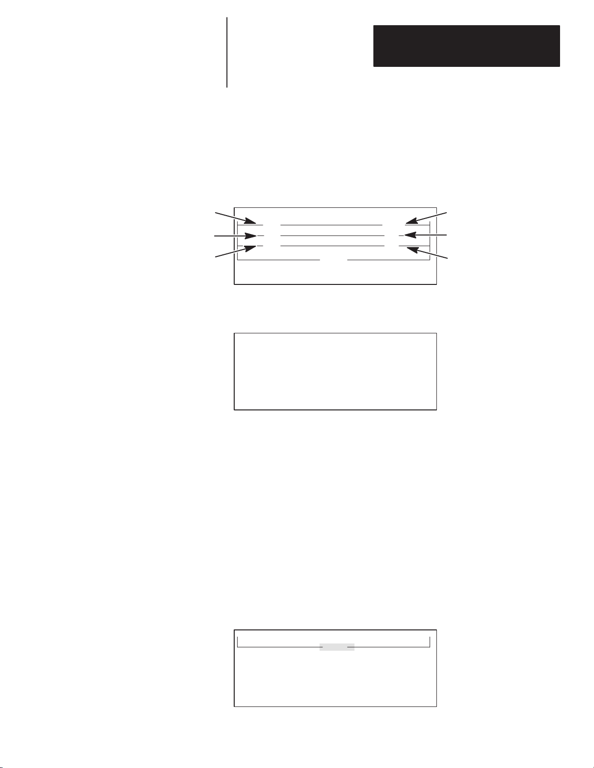
Getting Started Guide
for HHT
Appendix
A
Additional Ladder Program Exercises
Entering a Timer Instruction
T4:0/14
T4:0/13
In this exercise, you enter a timer instruction with a time delay of 10 seconds.
Two different types of timer status bits activate output pilot lights #0 and #1.
The first type, called a “timer timing” status bit turns on output #0 for 10
seconds. The second type, called a “done” status bit, turns on output #1 after
10 seconds.
The program that you will enter in this exercise will look like the one in the
display below:
I:1/0 TON
]
[
] [ ( )
] [ ( )
<END>
F1 F2 F3 F4 F5
(TON)
O:3/0
O:3/1
Start with the main display below:
SLC 500 PROGRAMMING SOFTWARE Rel. 2.03
Allen–Bradley Company Copyright 1990
1747 – PTA1E
All Rights Reserved
PRESS A FUNCTION KEY
SELFTEST TERM PROGMAINT
F1 F2 F3 F4 F5
1. [F5]
2.
3.
– UTILITY
[F5] – CLR_MEM
[F2] – YES
OFL
UTILITY
4. [ESC]
5. Rename program as shown in chapter 3, Creating a Program.
6. Reconfigure the controller as shown in chapter 3, Creating a Program.
Entering the Program
1. Press [F3]
2. Enter file number
– PROGMAINT
2, then press [ENTER]. The following display appears:
<END>
, then [F3]
2.0.0.0.*
– EDT_FIL
.
OFL
INS_RNG MOD_RNG SEARCH DEL_RNG UND_RNG
F1 F2 F3 F4 F5
>
A–5
Page 53

Appendix
A
Additional Ladder Program Exercises
] [
<END>
] [
<END>
(TON)
3. Enter a rung and an XIC instruction. Press or enter the following:
[F1]
A.
B.
C.
D.
– INS_RNG
[F1] – INS_INST
[F1] – BIT
[F1] —] [—
E. I:1/0
F. [ENTER]
G.
[F5] – ACCEPT
H. [ESC]
4. Enter the Timer Instruction. Press or enter the following:
[F2]
A.
B.
– TMR/CNT
[F1] – TON
C. T4:0 (This is the Timer Address.)
] [
] [
<END>
(TON)
[ENTER]
D.
E. 1000 (This is the Timer Preset Value in hundredths of a second.)
[ENTER]
F.
G. 0 (This is the Timer Accumulated Value.)
[ENTER]
H.
I. [F5]
– ACCEPT
J. [ESC]
K. [ESC]
L.
[F5] – ACP_RNG
5. Enter a second rung and an XIC instruction. Press or enter the following:
[F1]
A.
B.
C.
D.
– INS_RNG
[F1] – INS_INST
[F1] – BIT
[F1] —] [—
E. T4:0/14 (14 represents the timer timing bit.)
F.
[ENTER]
A–6
G. [F5]
– ACCEPT
Page 54

] [
] [
] [
] [
] [
Getting Started Guide
(TON)
<END>
(TON)
( )
<END>
for HHT
Appendix
A
Additional Ladder Program Exercises
6. Enter an OTE instruction. Press or enter the following:
[F3]
A.
—( )—
B. O:3/0
C. [ENTER]
D.
[F5] – ACCEPT
E. [ESC]
F. [ESC]
G.
[F5] – ACP_RNG
7. Enter a third rung and an XIC instruction. Press or enter the following:
A.
[F1]
– INS_RNG
B.
[F1] – INS_INST
C.
[F1] – BIT
D.
[F1] —] [—
E. T4:0/13 (13 represents the done bit.)
F.
[ENTER]
G. [F5]
– ACCEPT
8. Enter an OTE instruction. Press or enter the following:
A.
[F3]
—( )—
B. O:3/1
C. [ENTER]
D.
[F5] – ACCEPT
E. [ESC]
F. [ESC]
G.
[F5] – ACP_RNG
Your final display should look like this:
2.3.0.0.*
]
[
] [ ( )
] [ ( )
<END>
INS_RNG MOD_RNG SEARCH DEL_RNG UND_RNG
F1 F2 F3 F4 F5
(TON)
OFL
>
A–7
Page 55

Appendix
Additional Ladder Program Exercises
A
9. Save the program. Press or enter the following:
[ENTER]
A.
B. [F5]
C.
– SAVE_EX
[F5] – ACCEPT
D. [ESC]
10.Go online and run the program. Press or enter the following:
[F5]
A.
B.
C.
D.
E.
F.
– UTILITY
[F2] – WHO
[F3] – ATTACH
[F4] – MODE
[F5] – PROGRAM
[F2] – YES
G. [ESC]
H. [DWNLOAD]
I.
[F2] – YES
11. Monitor the ladder program. Press or enter the following:
A.
[ENTER]
B. [F5]
– MONITOR
C. 2
D. [ENTER]
12.Change Processor Mode to Run. Press or enter the following:
A.
[F1]
– MODE
B.
[F1] – RUN
C.
[F2] – YES
D. [ESC]
A–8
Page 56
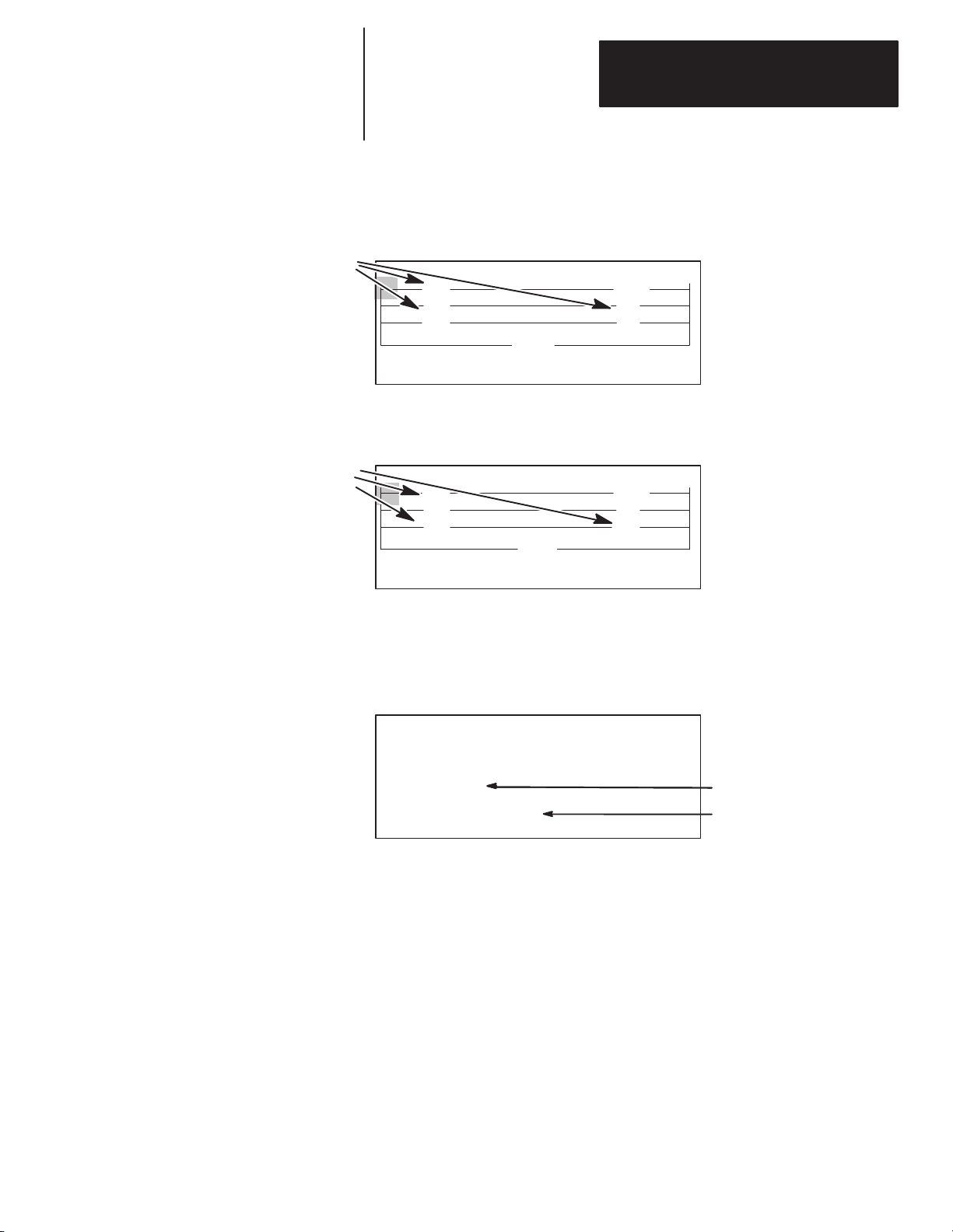
Getting Started Guide
These
bit instructions become bold.
for HHT
Appendix
A
Additional Ladder Program Exercises
13.Test your Ladder Program. Do the following:
A. Press pushbutton #0 for at least 10 seconds. During the first 10
seconds, output #0 turns ON and #1 stays OFF. The following display
appears:
2.3.0.0.*
]
[
] [ ( )
] [ ( )
<END>
MODE FORCE SEARCHEDT_DAT
F1 F2 F3 F4 F5
(TON)
RUN
B. After 10 seconds, output #0 turns OFF and output #1 turns ON. The
following screen appears:
These
bit instructions become bold.
2.3.0.0.*
]
[
] [ ( )
] [ ( )
<END>
MODE FORCE SEARCHEDT_DAT
F1 F2 F3 F4 F5
(TON)
RUN
C. Release pushbutton #0; the timer resets and both outputs #0 and #1
turn OFF.
TON
D. Place the cursor on the
[ZOOM]. The following screen appears:
Press
ZOOM on TON –(TON)–
NAME: TIMER ON DELAY
TIMER: T4:0 TIME BASE .01 SEC
PRESET: 1000
ACCUM: 0
EDT_DAT
F1 F2 F3 F4 F5
EN TT DN
000
instruction (press the [→ ] key twice).
2.0.0.0.2
The accumulator value changes
In step (e).
Notice that the values for EN,
TT, and DN also change.
E. Repeat steps A, B and C. Watch the timer accumulator value change.
A–9
Page 57

Page 58

Getting Started Guide
for HHT
Appendix
A–B
B
Troubleshooting Errors
This appendix shows you how to identify and correct errors that you may
encounter while working through this guide. They include:
• HHT error messages
• System LED status
• Processor error codes
HHT Error Messages
The table below details error messages.
This Error
Message:
Change Processor
to Program Mode
Default File in
Processor
Download Denied,
Compiler Errors
Error: Undefined
I/O Address
Appears when: Correct the Error by:
You attempt to download a
program from the HHT to a
processor that is in RUN
mode.
You clear the processor
memory, which is then
automatically loaded with a
“Default” program.
You attempt to download a
program saved with errors
(possibly I/O configuration
errors).
A mismatch exists between
the I/O addresses used in the
ladder program and the
configured I/O modules.
Entering the MODE menu to change the processor
from the RUN to PROGRAM mode.
Downloading a program from the HHT memory in
order to monitor controller operation.
Going offline and checking the ladder program for
any discrepancies between the I/O configuration
and addresses used in the program. Either edit the
program and change the address to agree with the
configured I/O modules, or re–configure the I/O to
match the entered address. For the latter, refer to
chapter 3 for extra help. Important: You can SAVE
the program with errors (to correct at a later time),
but you cannot download the program to the
processor.
Either editing the program and changing the
address to agree with the configured I/O modules,
or re–configuring the I/O to match the entered
address. For the latter, refer to chapter 3 for extra
help. Important: You can SAVE the program with
errors (to correct at a later time), but you cannot
download the program to the processor.
Illegal Operand
Illegal Network
Incompatible
Processor Type
An address that you entered
is not in the correct format.
You have a release of the
HHT memory pak (<2.0) that
does not support DH–485
network communications.
The processor that you have
configured in your program
does not match the processor
your HHT is communicating
with.
Refering to chapter 2, Control Basics, for proper
addressing format.
Obtaining an upgraded memory pak (release 2.0 or
greater) from your local Allen–Bradley Sales Office
or Distributor.
Going offline and changing the processor type in
the Processor Configuration. For extra help, see
chapter 3.
B–1
Page 59

Appendix B
T
roubleshooting Errors
This Error
Message:
Not a Processor
Program Files
Differ
Warning:
Undefined I/O
Referenced
Appears when: Correct the Error by:
Either you are trying to
ATTACH the HHT to either
itself or a non–processor
device while in the WHO
utility.
Using the
[
↓ ] or
[
↑ ] keys to change the order of
the nodes listed on the WHO screen. Put the
processor at the top of the list and try to
re–ATTACH.
Changing the communication parameters of the
HHT in the node configuration menu. From the
Or you are trying to ATTACH
the HHT to a non–existent
device, or no devices are
shown on the WHO screen.
WHO screen, press [F4]
changing the baud rate by pressing [F3]
the node address by pressing [F1]
or the maximum node address by pressing [F2]
MAX_ADR. Try different combinations. (The
processor defaults at node address 1 and baud
rate 19200.)
Making the programs the same by either uploading
The ladder program in the
processor memory does not
match the program stored in
the HHT memory.
The address you entered
does not match the I/O
configuration.
the processor program into the HHT (overwriting
the HHT memory) or downloading the HHT
program to the processor (overwriting the
processor memory). Caution: The overwritten
program is lost.
Either changing the address to agree with the
configured I/O modules or exiting the edit mode
and re–configuring the I/O to match the entered
address. For the latter, refer to chapter 3, Creating
a Program, for extra help.
– NODE_CFG.
BAUD
CHG_ADR
Try
,
,
B–2
Page 60

Getting Started Guide
for HHT
Appendix B
T
roubleshooting Errors
System LED Status
Modular System
The System LEDs are located at different places on the modular system and
the SLC fixed controller. Refer to the Installation and Operation manual for
more information on system LED status. See the figure and table below:
SLC 500 Fixed Controller
POWER
POWER
PC RUN
CPU FAULT
PC RUN
CPU FAULT
FORCED I/O
BATTERY LOW
Processor LED Status of LED Cause Corrective Action
Verify line power within range. Verify
wiring and grounding. Check power
supply fuse. For modular system,
POWER Off No DC power to backplane
verify power supply jumper is positioned correctly and that the power
supply has been sized properly for
loading in the rack.
Verify
that position of notch in proces
CPU FAULT Steady Bad CPU or firmware improperly
installed
sor firmware chip matches processor
board diagram. See corrective action
for Power LED.
Correct the problem based on the
ror message. First clear the fault.
CPU FAULT Flashing Processor major fault
Then press and return processor to
RUN mode. See processor error
codes.
BATTERY LOW Steady
Battery voltage fallen below threshold to retain RAM memory; or no
battery present; or LED jumper is
missing
Replace
1747–BA and
processor power; or add 1747–BA to
retain RAM memory; or add LED
jumper to prevent the LED from
lighting.
FORCED I/O
BATTERY LOW
do not remove
er
-
-
B–3
Page 61

Appendix B
T
roubleshooting Errors
Processor Error Codes
The table below details some of the processor error codes. Refer to the HHT
manual for a complete list of error codes and troubleshooting information.
Error Code Cause Corrective Action
RAM program is corrupt due to
0001
0012
XX50, XX51, XX52
XX53, XX54, XX55
(xx = slot #)
0056 Rack configuration error.
noise, lightning, improper
grounding, or loss of capacitor or
battery back–up.
RAM program is corrupt or RAM
itself is bad due to noise, lightning, improper grounding, or loss
of capacitor or battery back–up.
I/O module configuration/conflict
or runtime problem.
Check wiring, layout, and grounding. If using a 4K
CPU,
verify that a battery
memory when power is removed. See CPU
FAULT–Flashing
load the program using the HHT.
Check
wiring, layout, grounding. If using a 4K CPU,
verify that a battery is installed to retain RAM
memory when power is removed. See CPU
FAULT–flashing under system LED status. Download the program using HHT.
Verify that processor configuration matches your
hardware. See chapter 3 on configuring for key-
Also see CPU F
strokes.
System LED status.
Verify that rack configuration in your program
matches
your hardware.
ing for keystrokes. If multiple rack system, verify
proper installation of rack interconnect cable. See
F
AUL
CPU
tus.
T — Flashing — under system LED sta
is installed to retain RAM
under system LED status. Down
AUL
T —
Flashing — under
See chapter 3 on configur
-
-
-
B–4
Page 62

Getting Started Guide
for HHT
Appendix
A–B
C
Identifying HHT Function Keys & Instruction
Mnemonics
This appendix provides a listing of the abbreviated function keys and their
meaning. It also provides a list of instruction mnemonics.
HHT Function Keys and Their Meaning
Below is a list of abbreviated function keys and their meaning.
Abbreviation: Meaning:
ACCUM accumulator value
ACP_RNG accept rung
ADDR address
APP_BR append branch
B battery
CAN_ED cancel edit
CAN_RNG cancel rung
CHG_NAM change name
CLR_MEM clear memory
CLR_PRC clear processor
CONT continuous
CPT/MTH compute/math
CRT_DT create data
CRT_FIL create file
CSN continuous scan
CUR_INS current instruction
CUR_OPD current operand
DEL_BR delete branch
DEL_DT delete data
DEL_FIL delete file
DEL_INS delete instruction
DEL_RNG delete rung
DEL_SLT delete slot
DWNLOAD download
EDT_DAT edit data
EDT_FIL edit file
EDT_I/O edit I/O
C–1
Page 63

Appendix C
Identifying HHT
Mnemonics
Function Keys & Instruction
Abbreviation: Meaning:
ENT enter
ENT_MAS enter master
EXEC_FILE executable files
EXT_DWN extend down
EXT_UP extend up
F force
FLT fault
INS_BR insert branch
INS_INST insert instruction
INS_RNG insert rung
I/O_MSG I/O message
MEM_MAP memory map
MEM_PRC memory module to processor
MEM_SIZ memory size
MOD_INS modify instruction
MOD_RCK modify rack
MOD_RNG modify rung
MOD_SLT modify slot
MOR_CPT more compute
MOV/LOG move/logic
NEW_INS new instruction
NEW_PRG new program
NEXT_FL next file
NEXT_PG next page
OFL offline
PASSWRD password
PRC_MEM processor to memory module
PREV_FL previous file
C–2
PREV_PG previous page
PRG program
PRG_SIZE program size
PROGMAINT program maintenance
RLY relay
REM remove
REM_ALL remove all
Page 64

Getting Started Guide
for HHT
Abbreviation: Meaning:
REM_MAS remove master
SAVE_CT save and continue
SAVE_EX save and exit
SEL_PRO select processor
SFT/SEQ shift/sequencer
SNK sink
SRC source
SSN single scan
TMR/CNT timer/counter
TRANS transistor
UND_INST undelete instruction
Appendix C
Identifying HHT
Mnemonics
Function Keys and Instruction
Instruction Mnemonics
UND_RNG undelete rung
WTCHDOG watchdog
XFERMEM transfer memory
The table below provides a complete list of instruction mnemonics.
Mnemonic: Instruction:
ADD add
AND and
BSL bit shift left
BSR bit shift right
CLR clear
COP copy file
CTD count down
CTU count up
DCD decode 4 to 1 of 16
DDV double divide
DIV divide
EQU equal
FFL FIFO load
FFU FIFO unload
FLL fill file
FRD convert from BCD
GEQ greater than or equal to
C–3
Page 65

Appendix C
Identifying HHT
Mnemonics
Function Keys & Instruction
Mnemonic: Instruction:
GRT greater than
HSC high–speed counter
IID I/O interrupt disable
IIE I/O interrupt enable
IIM immediate input with mask
INT I/O Interrupt
IOM immediate output with mask
JMP jump to label
JSR jump to subroutine
LBL label
LEQ less than or equal to
LES less than
LFL LIFO load
LFU LIFO unload
LIM limit test
MCR master control reset
MEQ masked comparison for equal
MOV move
MUL multiply
MVM masked move
NEG negate
NEQ not equal
NOT not
OR or
OSR one shot rising
OTE output energize
OTL output latch
OTU output unlatch
C–4
PID proportional integral derivative
REF I/O refresh
RES reset
RET return from subroutine
RPI reset pending I/O interrupt
RTO retentive on–delay timer
SBR subroutine
Page 66

Getting Started Guide
for HHT
Mnemonic: Instruction:
SCL scale data
SQC sequencer compare
SQL sequencer load
SQO sequencer output
SQR square root
STD STI disable
STE STI enable
STS STI start immediately
SUB subtract
SUS suspend
SVC service communications
Appendix C
Identifying HHT
Mnemonics
Function Keys and Instruction
TND temporary end
TOD convert to BCD
TOF timer off–delay
TON timer on–delay
XIC examine if closed
XIO examine if open
XOR exclusive or
C–5
Page 67

Appendix C
Identifying HHT
Mnemonics
Function Keys & Instruction
C–6
Page 68

Getting Started Guide
for HHT
Glossary
A–B
Glossary
The following terms are used throughout this manual. Refer to them while
working in this manual.
address: A character string that uniquely identifies a memory location. For
example, I:1/0 is the memory address for the data located in the Input file
location 1/0.
APS: (Advanced Programming Software) Software for a computer used to
monitor and develop SLC 500 ladder logic programs.
attach: To establish communication with a processor.
bit: The smallest storage location in memory that contains either a 1 (ON) or
a 0 (OFF).
branch: A parallel logic path within a rung of a ladder program.
communication scan: A part of the SLC’s operating cycle. Communication
with other devices, such as the HHT, takes place.
controller: A device, such as a programmable controller, used to monitor
input devices and control output devices.
CMOS (Complementary Metal–Oxide Semiconductor): A semiconductor
device in which an electric field controls the conductance of a channel under
a metal electrode called a gate.
CPU (Central Processing Unit): The decision–making and data storage
section of a programmable controller.
data file: An area within a processor file that contains the status of inputs,
outputs, the processor, timers, counters, and so on.
download: To transfer a program from HHT memory to an SLC.
edit: To create or modify a ladder program.
expansion rack: A 2–slot rack used only with fixed controllers.
false: The status of an instruction that does not provide a continuous logical
path on a ladder rung.
file: A collection of information organized into one group.
fixed controller: A controller with a power supply, CPU, and I/O integrated
into a single package.
function keys: Keys on a personal computer or HHT keyboard labeled F1,
F2 and so on. The operation of each of these keys is defined by HHT.
hardware: The components that comprise a programmable controller, such
as Input modules, Output modules, and the CPU.
HHT: Hand–held Terminal.
I/O (Inputs and Outputs): Consists of input and output devices which
provide and/or receive data from the programmable controller.
G–1
Page 69

Glossary
input device: A device, such as a pushbutton or a switch, that supplies data
through input circuits to a programmable controller.
input scan: A part of the SLC’s operating cycle. Status of the input
modules are loaded into the Input data file.
instruction: A mnemonic and data address defining an operation to be
performed by the processor. A rung in a program consists of a set of input
and output instructions. The input instructions are evaluated by the SLC as
being true or false. In turn, the SLC sets the output instructions to true or
false.
ladder logic: A program written in a format resembling a ladder–like
diagram. The program is used by a programmable controller to control
devices.
memory: An area in either an HHT or processor that stores the ladder
program (progam and data files).
memory pak: A circuit board that goes into the back of the HHT containing
the software and language to operate the HHT.
mnemonic: A three–letter abbreviation for a ladder programming
instruction.
modular controller: SLC 500 system consisting of a power supply, racks,
CPU, and input and output modules.
module: An interchangeable plug–in device that may be inserted into a rack.
network: A series of devices connected by a communication medium.
offline: Describes devices not under direct communication. For example,
when programming with an HHT.
online: Describes devices under direct communication. For example, when
the HHT is monitoring the program file in a SLC. Also, a function in the
HHT to establish communications with an SLC after using the WHO screen.
operating cycle: The sequential order of operations performed by the
processor when in the run mode.
OTE (OuTput Energize): An instruction that energizes when a rung is true
and de–energizes when a rung is false.
output device: A device, such as a pilot light or a motor starter coil, that
receives data from the programmable controller.
output scan: A part of the SLC’s operating cycle. During this scan the
output data file information is transferred to the output modules.
processor: See CPU.
G–2
processor file: The set of Program and Data Files used by the SLC to
control output devices. Only one processor file may be stored in the SLC at
a time. In HHT terminology program is equivalent to processor file.
processor overhead: An internal portion of the operating cycle used for
house–keeping and set–up purposes.
program: The set of Program and Data Files used by the SLC to control
output devices. Only one processor file may be stored in the SLC at a time.
In HHT terminology program is equivalent to processor file.
Page 70

Getting Started Guide
for HHT
Glossary
program file: The area within a processor file that contains the ladder logic
program.
program mode: When the SLC is not executing the processor file and all
outputs are de–energized.
program scan: A part of the SLC’s operating cycle. During the scan the
ladder program is executed and the Output data file is updated based on the
program and the Input data file.
rack (chassis): A hardware assembly that houses devices such as I/O
modules, processor modules, and power supplies.
read: To acquire data from a storage place. For example, the processor
READs information from the input data file to solve the ladder program.
restore: To download (transfer) a program from the HHT to an SLC.
run mode: When the processor file in the SLC is being executed, inputs are
read, the program is scanned, and outputs are energized and de–energized.
rung: Ladder logic is comprised of a set of rungs. A rung contains input
and output instructions. During Run mode, the inputs on a rung are
evaluated to be true or false. If a path of true logic exists, the outputs are
made true. If all paths are false, the outputs are made false.
SLC (Small Logic Controller): A controller that comes in one of two
styles: fixed or modular.
slot: The area in a rack that a module plugs into.
software: Executable programming package used to develop SLC ladder
diagrams.
status: The condition of a circuit or system, represented as logic 0 (OFF) or
1 (ON).
terminal: A point on an I/O module that external I/O devices, such as a
pushbutton or pilot light, are wired to.
true: The status of an instruction that provides a continuous logical path on
a ladder rung.
upload: To transfer a program from an SLC to the HHT memory.
WHO: A utility in the HHT that lets you view the devices on your DH–485
network.
write: To copy data to a storage device. For example, the processor
WRITEs the information from the output data file to the output modules.
eXamine If Closed (XIC): An input instruction that is logically true when
the status of the bit located at its address is a 1; false when it’s a 0.
eXamine If Open (XIO): An input instruction that is logically true when
the status of the bit located at its address is a 0; false when it’s a 1.
G–3
Page 71

Glossary
G–4
Page 72

Index
The Getting Started Guide for HHT
User Manual
A
addresses
display
of, 2–5
formats of, 2–5
specifying, 2–4
input, 2–4
output, 2–4
Allen–Bradley
contacting for assistance, P–3
auto shift, 1–10
, P–3
B
battery
, installation, 1–6
Battery T
blue keys, 1–10
est Failed statement, 1–6
C
catalog numbers, 3–2
locating, 3–3
recording, 3–2
changing Program mode to Run mode, 4–3
clearing the memory of the HHT
communication cable, installation, 1–7
configuration of controllers, 3–1
catalog numbers, 3–2
controller used in this guide, 3–4
styles, 3–2
contacting Allen–Bradley for assistance, P–3
contents of manual, P–2
controller styles, 1–2
fixed, 1–2, 3–2
modular
, 1–2, 3–2
creating a program, 3–4
clearing the memory
naming the program and configuring the
controller
programming a simple ladder rung, 3–1
saving your program, 3–14
cursor movement, 1–10
, 3–5
, 3–6
, 3–5
1
D
data files, 2–1, 2–2
default types, 2–2
input, 2–2
output, 2–2
timer
, 2–2
monitoring, 3–10, 4–5
DEFAUL
demonstration unit
display format, 1–9
displaying addresses, 2–5
downloading your program, 4–2
T program, 3–5
components, 3–4
setting up, 1–3
changing to Run mode, 4–3
downloading, 4–3
going online, 4–2
monitoring in Run mode, 4–4
E
END rung, 3–1
ENTER key
entering
input and output branches, A–1
adding an input branch, A–2
adding an output branch, A–2
creating the program, A–1
downloading the program, A–3
inserting an instruction, A–2, A–3
saving the program, A–3
testing the ladder program, A–4
rungs, 3–1
timer instructions, A–5
error codes, B–4
errors
illegal network, B–1
illegal operand, B–1
incompatible processor type, B–1
not a processor
program files dif
ESC key
Examine if Closed instruction, 3–12
external input/output devices
addressing, 2–4
communicating with the processor
1
, 1–9
1
, 1–9, 1–10
, B–2
fer
, B–2
, 2–3
data file bits
logic 0, 2–6
logic 1, 2–6
I–1
Page 73

Index
The Getting Started Guide for HHT
User Manual
F
false rung conditions, 2–7
features, of HHT
field–wired controller
file concepts, 2–1
data files, 2–1, 2–2
processor file, 2–1
program, 2–1
program files, 2–1, 2–2
fixed controller
components, 1–2, 3–2
demonstration unit, 1–3
installing and wiring, 1–4
slot numbers, 3–2
function keys, meanings, C–1
FUT
ACC (Future Access), 3–14
, 1–8
, setting up, 1–4
, 1–2
G
going online, 4–2
green keys, 1–10
instructions, inserting, A–2, A–3
K
keyboard operation, 1–9
auto shift, 1–10
cursor keys, 1–10
data entry keys, 1–10
menu function keys, 1–9
ZOOM and RUNG keys, 1–10
L
ladder logic concepts, 2–6
logical continuity
processor operating cycle, 2–8
true/false status, 2–6
LED status, B–3
locating, catalog numbers, 3–3
logical continuity
, 2–7
, 2–7
M
H
HHT
clearing the memory
display format, 1–9
error messages, B–1
features, 1–8
keyboard operation, 1–9
powerup, 1–9
, 3–5
I
illegal network error
illegal operand error
incompatible processor type error
input branch, entering, A–1, A–2
input data file, 2–2
monitoring, 3–10, 4–5
installing the
battery
, 1–6
communication cable, 1–7
memory pak, 1–4
instruction mnemonics, C–3
instruction status, 2–6
false, 2–6
true, 2–6
, B–1
, B–1
, B–1
manuals, related, P–2, 1–2, 1–4
memory
, clearing, 3–5
memory pak, installation, 1–4
Menu tree functions, 1–9
modular controller
components, 1–2, 3–2
demonstration unit, 1–3, 3–1, 3–4
installing and wiring, 1–4
slot numbers, 3–2
monitoring
input and output data files, 4–5
the program in Run mode, 4–4
moving the cursor
, 1–2
, 1–10
N
naming the program and configuring the
controller
configuring the processor
configuring your I/O, 3–8
monitoring your data file, 3–10
naming your program, 3–6
notes on terminology
, 3–6
, 3–7
, 2–1
I–2
Page 74

Index
The Getting Started Guide for HHT
User Manual
O
operating cycle, processor
output branch, entering, A–1, A–2
output data file, 2–2
monitoring, 3–10, 4–5
Output Energize instruction, 3–13
, 2–8
P
powering up, 1–9
processor error codes, B–4
processor operating cycle, 2–8
program files dif
Program mode, changing to Run mode, 4–3
fer error
, B–2
programming a simple ladder rung, 3–1
entering a rung, 3–1
Examine if Closed instruction, 3–12
Output Energize instruction, 3–13
publications, related, P–2, 1–2, 1–4
purple keys, 1–9
1
R
recording, catalog numbers, 3–2
Run mode
changing from Program mode to, 4–3
monitoring the program in, 4–4
RUNG key
, 1–10
1
I–3
Page 75

Page 76

Page 77

With offices in major cities worldwide.
A subsidiary of Rockwell International, one of the world’s largest technology companies,
Allen-Bradley meets today’s automation challenges with over 85 years of practical plant floor
experience. 11,000 employees throughout the world design, manufacture and apply a wide
range of control and automation products and supporting services to help our customers
continuously improve quality, productivity and time to market. These products and services
not only control individual machines, but also integrate the manufacturing process while
providing access to vital plant floor data that can be used to support decision–making
throughout the enterprise.
WORLD HEADQUARTERS
Allen-Bradley
1201 South Second Street
Milwaukee, WI 53204 USA
Tel: (1) 414 382–2000
Telex: 43 11 016
FAX: (1) 414 382–4444
EUROPE/MIDDLE EAST/
AFRICA HEADQUARTERS
Allen–Bradley Europe B.V.
Amsterdamseweg 15
1422 AC Uithoorn
The Netherlands
Tel: (31) 2975/43500
Telex: (844) 18042
FAX: (31) 2975/60222
1747–NM009 Series BFebruary, 1993
Supersedes 1747–NM009 Series AMay, 1992
ASIA/PACIFIC HEADQUARTERS
Allen–Bradley
1201 South Second Street
Milwaukee, WI 53204 USA
Tel: (1) 414 382-2000
Telex: 43 11 016
FAX: (1) 414 382-2400
CANADA HEADQUARTERS
Allen–Bradley Canada Limited
135 Dundas Street
Cambridge, Ontario N1R 5X1
Canada
Tel: (1) 519 623–1810
FAX: (1) 519 623–8930
1993 Allen-Bradley Company Printed in USA
LATIN AMERICA
HEADQUARTERS
Allen-Bradley
1201 South Second Street
Milwaukee, WI 53204 USA
Tel: (1) 414 382–2000
Telex: 43 11 016
FAX: (1) 414 382–2400
40063–169–01(A)
 Loading...