

Page 1

Hand–Held Terminal
(Catalog Number 1747–PT1)
User Manual
ALLEN–BRADLEY
Page 2

Important User Information
Solid state equipment has operational characteristics differing from those of
electromechanical equipment. “Safety Guidelines for the Application,
Installation and Maintenance of Solid State Controls” (Publication SGI-1.1)
describes some important differences between solid state equipment and
hard–wired electromechanical devices. Because of this difference, and also
because of the wide variety of uses for solid state equipment, all persons
responsible for applying this equipment must satisfy themselves that each
intended application of this equipment is acceptable.
In no event will the Allen-Bradley Company be responsible or liable for
indirect or consequential damages resulting from the use or application of
this equipment.
The examples and diagrams in this manual are included solely for illustrative
purposes. Because of the many variables and requirements associated with
any particular installation, the Allen-Bradley Company cannot assume
responsibility or liability for actual use based on the examples and diagrams.
No patent liability is assumed by Allen-Bradley Company with respect to use
of information, circuits, equipment, or software described in this manual.
Reproduction of the contents of this manual, in whole or in part, without
written permission of the Allen-Bradley Company is prohibited.
Throughout this manual we use notes to make you aware of safety
considerations.
ATTENTION: Identifies information about practices or
circumstances that can lead to personal injury or death, property
!
damage, or economic loss.
Attentions help you:
• identify a hazard
• avoid the hazard
• recognize the consequences
Important: Identifies information that is especially important for successful
application and understanding of the product.
PLC, PLC 2, PLC 3, and PLC 5 are registered trademarks of Allen-Bradley Company, Inc.
SLC, SLC 100, SLC 500, SLC 5/01, SLC 5/02, PanelView, RediPANEL, and Dataliner are trademarks of Allen-Bradley Company, Inc.
IBM is a registered trademark of International Business Machines, Incorporated.
Page 3

Summary of Changes
Summary of Changes
The information below summarizes the changes to this manual since the last
printing as 1747–809 in July 1989, which included the supplement
40063–079–01(A) from October 1990.
New Information
The table below lists sections that document new features and additional
information about existing features, and shows where to find this new
information.
For This New Information See Chapter
4 – Data File Organization and Addressing
6 – Creating a Program
Using the HHT with an SLC
Using the HHT with an SLC
5/02 (in general)
32–Bit Addition and
Subtraction
Index Register
Index Register
DH–485 devices 9 – Configuring Online Communication
User Fault Routine
Selectable Timed Interrupts
I/O Interrupts 31 – Understanding I/O Interrupts – SLC 5/02 Processor Only
Instruction Execution Times C – Memory Usage, Instruction Execution Times
Scan Time Worksheets D – Estimating Scan Time
8 – Saving and Compiling a Program
14 – Using EEPROMs and UVPROMs
15 – Instruction Set Overview
27 – The Status File
20 – Math Instructions
22 – File Copy and File Fill Instructions
23 – Bit Shift, FIFO, and LIFO Instructions
24 – Sequencer Instructions
28 – Troubleshooting Faults
29 – Understanding the User Fault Routine – SLC 5/02
Processor Only
30 – Understanding Selectable Timed Interrupts – SLC 5/02
Processor Only
Page 4

Page 5

Table of Contents
Hand–Held T erminal
User Manual
Preface
Who Should Use this Manual P–1. . . . . . . . . . . . . . . . . . . . . . . . . . . . . . . . . . .
Purpose of this Manual P–1. . . . . . . . . . . . . . . . . . . . . . . . . . . . . . . . . . . . . . . .
Contents of this Manual P–2. . . . . . . . . . . . . . . . . . . . . . . . . . . . . . . . . . . . . . .
Related Documentation P–4. . . . . . . . . . . . . . . . . . . . . . . . . . . . . . . . . . . . .
Common Techniques Used in this Manual P–4. . . . . . . . . . . . . . . . . . . . . . . . . .
Allen–Bradley Support P–5. . . . . . . . . . . . . . . . . . . . . . . . . . . . . . . . . . . . . . . .
Local Product Support P–5. . . . . . . . . . . . . . . . . . . . . . . . . . . . . . . . . . . . . .
Technical Product Assistance P–5. . . . . . . . . . . . . . . . . . . . . . . . . . . . . . . . .
Your Questions or Comments on this Manual P–5. . . . . . . . . . . . . . . . . . . . . .
Features, Installation,
Powerup
The Menu Tree
Chapter 1
HHT Features 1–1. . . . . . . . . . . . . . . . . . . . . . . . . . . . . . . . . . . . . . . . . . . . . .
Installing the Memory Pak, Battery, and Communication Cable 1–3. . . . . . . . . . .
HHT Powerup 1–7. . . . . . . . . . . . . . . . . . . . . . . . . . . . . . . . . . . . . . . . . . . . . .
HHT Display Format 1–8. . . . . . . . . . . . . . . . . . . . . . . . . . . . . . . . . . . . . . . . .
The Keyboard 1–9. . . . . . . . . . . . . . . . . . . . . . . . . . . . . . . . . . . . . . . . . . . . . .
Menu Function Keys (F1, F2, F3, F4, F5) 1–9. . . . . . . . . . . . . . . . . . . . . . . . .
Data Entry Keys 1–9. . . . . . . . . . . . . . . . . . . . . . . . . . . . . . . . . . . . . . . . . .
Auto Shift 1–9. . . . . . . . . . . . . . . . . . . . . . . . . . . . . . . . . . . . . . . . . . . . . . .
Cursor Keys 1–10. . . . . . . . . . . . . . . . . . . . . . . . . . . . . . . . . . . . . . . . . . . . .
ZOOM and RUNG Keys 1–12. . . . . . . . . . . . . . . . . . . . . . . . . . . . . . . . . . . . .
Chapter 2
Using the HHT Menu 2–1. . . . . . . . . . . . . . . . . . . . . . . . . . . . . . . . . . . . . . . . .
Progressing through Menu Displays 2–1. . . . . . . . . . . . . . . . . . . . . . . . . . . .
The ENTER Key 2–2. . . . . . . . . . . . . . . . . . . . . . . . . . . . . . . . . . . . . . . . . .
The ESCAPE Key 2–2. . . . . . . . . . . . . . . . . . . . . . . . . . . . . . . . . . . . . . . . .
The Main Menu 2–3. . . . . . . . . . . . . . . . . . . . . . . . . . . . . . . . . . . . . . . . . . . . .
Main Menu Functions 2–3. . . . . . . . . . . . . . . . . . . . . . . . . . . . . . . . . . . . . . . . .
SELFTEST, [F1] 2–3. . . . . . . . . . . . . . . . . . . . . . . . . . . . . . . . . . . . . . . .
TERMINAL, [F2] 2–3. . . . . . . . . . . . . . . . . . . . . . . . . . . . . . . . . . . . . . . .
PROGRAM MAINTENANCE, [F3] 2–3. . . . . . . . . . . . . . . . . . . . . . . . . . . .
UTILITY, [F5] 2–4. . . . . . . . . . . . . . . . . . . . . . . . . . . . . . . . . . . . . . . . . . .
The Menu Tree 2–4. . . . . . . . . . . . . . . . . . . . . . . . . . . . . . . . . . . . . . . . . . . . .
HHT Function Keys and Instruction Mnemonics 2–11. . . . . . . . . . . . . . . . . . . . . .
Function Keys 2–11. . . . . . . . . . . . . . . . . . . . . . . . . . . . . . . . . . . . . . . . . . . .
Instruction Mnemonics 2–14. . . . . . . . . . . . . . . . . . . . . . . . . . . . . . . . . . . . . .
i
Page 6

Table of Contents
Hand–Held T erminal
User Manual
Understanding File
Organization
Data File Organization and
Addressing
Chapter 3
Program, Program Files, and Data Files 3–1. . . . . . . . . . . . . . . . . . . . . . . . . . .
Program 3–2. . . . . . . . . . . . . . . . . . . . . . . . . . . . . . . . . . . . . . . . . . . . . . . .
Program Files 3–2. . . . . . . . . . . . . . . . . . . . . . . . . . . . . . . . . . . . . . . . . . . .
Data Files 3–3. . . . . . . . . . . . . . . . . . . . . . . . . . . . . . . . . . . . . . . . . . . . . . .
Downloading Programs 3–3. . . . . . . . . . . . . . . . . . . . . . . . . . . . . . . . . . . . .
Uploading Programs 3–4. . . . . . . . . . . . . . . . . . . . . . . . . . . . . . . . . . . . . . .
Using EEPROM and UVPROM Memory Modules for Program Backup 3–4. . . .
Chapter 4
Data File Organization 4–1. . . . . . . . . . . . . . . . . . . . . . . . . . . . . . . . . . . . . . . .
Data File Types 4–2. . . . . . . . . . . . . . . . . . . . . . . . . . . . . . . . . . . . . . . . . . .
Addressing Data Files 4–2. . . . . . . . . . . . . . . . . . . . . . . . . . . . . . . . . . . . . . . .
Data File 2 – Status 4–3. . . . . . . . . . . . . . . . . . . . . . . . . . . . . . . . . . . . . . . .
Data Files 0 and 1 – Outputs and Inputs 4–4. . . . . . . . . . . . . . . . . . . . . . . . .
Data File 3 – Bit 4–8. . . . . . . . . . . . . . . . . . . . . . . . . . . . . . . . . . . . . . . . . . .
Data File 4 – Timers 4–9. . . . . . . . . . . . . . . . . . . . . . . . . . . . . . . . . . . . . . . .
Data File 5 – Counters 4–10. . . . . . . . . . . . . . . . . . . . . . . . . . . . . . . . . . . . . .
Data File 6 – Control 4–11. . . . . . . . . . . . . . . . . . . . . . . . . . . . . . . . . . . . . . .
Data File 7 – Integer 4–12. . . . . . . . . . . . . . . . . . . . . . . . . . . . . . . . . . . . . . .
Indexed Addressing
SLC 5/02 Processors Only 4–13. . . . . . . . . . . . . . . . . . . . . . . . . . . . . . . . . .
Offset Value (S:24 Index Register ) 4–13. . . . . . . . . . . . . . . . . . . . . . . . . . . . .
Example 4–13. . . . . . . . . . . . . . . . . . . . . . . . . . . . . . . . . . . . . . . . . . . . . .
Creating Data for Indexed Addresses 4–14. . . . . . . . . . . . . . . . . . . . . . . . . . .
Crossing File Boundaries 4–14. . . . . . . . . . . . . . . . . . . . . . . . . . . . . . . . . . . .
Example 4–14. . . . . . . . . . . . . . . . . . . . . . . . . . . . . . . . . . . . . . . . . . . . . .
Monitoring Indexed Addresses 4–15. . . . . . . . . . . . . . . . . . . . . . . . . . . . . . . .
Example 4–15. . . . . . . . . . . . . . . . . . . . . . . . . . . . . . . . . . . . . . . . . . . . . .
Effects of File Instructions on Indexed Addressing 4–15. . . . . . . . . . . . . . . . . .
Effects of Program Interrupts on Index Register S:24 4–15. . . . . . . . . . . . . . . .
File Instructions – Using the File Indicator # 4–16. . . . . . . . . . . . . . . . . . . . . . . . .
Bit Shift Instructions 4–16. . . . . . . . . . . . . . . . . . . . . . . . . . . . . . . . . . . . . . . .
Sequencer Instructions 4–17. . . . . . . . . . . . . . . . . . . . . . . . . . . . . . . . . . . . . .
File Copy and File Fill Instructions 4–18. . . . . . . . . . . . . . . . . . . . . . . . . . . . . .
Creating Data 4–19. . . . . . . . . . . . . . . . . . . . . . . . . . . . . . . . . . . . . . . . . . . . . .
Creating Data for Indexed Addresses 4–19. . . . . . . . . . . . . . . . . . . . . . . . . . .
Deleting Data 4–20. . . . . . . . . . . . . . . . . . . . . . . . . . . . . . . . . . . . . . . . . . . . . .
Program Constants 4–20. . . . . . . . . . . . . . . . . . . . . . . . . . . . . . . . . . . . . . . . . .
M0 and M1 Data Files – Specialty I/O Modules 4–21. . . . . . . . . . . . . . . . . . . . . .
Addressing M0–M1 Files 4–21. . . . . . . . . . . . . . . . . . . . . . . . . . . . . . . . . . . .
Restrictions on Using M0-M1 Data File Addresses 4–21. . . . . . . . . . . . . . . . . .
Monitoring Bit Instructions Having M0 or M1 Addresses 4–22. . . . . . . . . . . . . .
ii
Page 7

Table of Contents
Hand–Held T erminal
User Manual
Transferring Data Between Processor Files and M0 or M1 Files 4–23. . . . . . . . .
Access Time 4–24. . . . . . . . . . . . . . . . . . . . . . . . . . . . . . . . . . . . . . . . . . . . .
Minimizing the Scan Time 4–25. . . . . . . . . . . . . . . . . . . . . . . . . . . . . . . . . . . .
Capturing M0–M1 File Data 4–26. . . . . . . . . . . . . . . . . . . . . . . . . . . . . . . . . .
Specialty I/O Modules with Retentive Memory 4–26. . . . . . . . . . . . . . . . . . . . .
G Data Files – Specialty I/O Modules 4–27. . . . . . . . . . . . . . . . . . . . . . . . . . . . .
Editing G File Data 4–28. . . . . . . . . . . . . . . . . . . . . . . . . . . . . . . . . . . . . . . . .
Ladder Program Basics
Chapter 5
Ladder Programming 5–1. . . . . . . . . . . . . . . . . . . . . . . . . . . . . . . . . . . . . . . . .
A 1–Rung Ladder Program 5–2. . . . . . . . . . . . . . . . . . . . . . . . . . . . . . . . . . . . .
Logical Continuity 5–3. . . . . . . . . . . . . . . . . . . . . . . . . . . . . . . . . . . . . . . . . . .
Series Logic 5–4. . . . . . . . . . . . . . . . . . . . . . . . . . . . . . . . . . . . . . . . . . . . . . .
Example – Series Inputs 5–4. . . . . . . . . . . . . . . . . . . . . . . . . . . . . . . . . . .
Parallel Logic 5–4. . . . . . . . . . . . . . . . . . . . . . . . . . . . . . . . . . . . . . . . . . . . . .
Example – Parallel Inputs 5–4. . . . . . . . . . . . . . . . . . . . . . . . . . . . . . . . . .
Input Branching 5–5. . . . . . . . . . . . . . . . . . . . . . . . . . . . . . . . . . . . . . . . . . .
Example – Parallel Input Branching 5–5. . . . . . . . . . . . . . . . . . . . . . . . . . .
Output Branching 5–5. . . . . . . . . . . . . . . . . . . . . . . . . . . . . . . . . . . . . . . . . .
Example – Parallel Output Branching 5–5. . . . . . . . . . . . . . . . . . . . . . . . .
Example – Parallel Output Branching with Conditions (SLC 5/02 Only) 5–6. .
Nested Branching 5–6. . . . . . . . . . . . . . . . . . . . . . . . . . . . . . . . . . . . . . . . .
Example – Nested Input and Output Branches 5–6. . . . . . . . . . . . . . . . . . .
Example 5–7. . . . . . . . . . . . . . . . . . . . . . . . . . . . . . . . . . . . . . . . . . . . . .
A 4–Rung Ladder Program 5–8. . . . . . . . . . . . . . . . . . . . . . . . . . . . . . . . . . . . .
Application Example 5–9. . . . . . . . . . . . . . . . . . . . . . . . . . . . . . . . . . . . .
Operating Cycle (Simplified) 5–11. . . . . . . . . . . . . . . . . . . . . . . . . . . . . . . . . . . .
When the Input Goes True 5–12. . . . . . . . . . . . . . . . . . . . . . . . . . . . . . . . .
When the Input Goes False 5–13. . . . . . . . . . . . . . . . . . . . . . . . . . . . . . . .
Creating a Program
Chapter 6
Creating a Program Offline with the HHT 6–1. . . . . . . . . . . . . . . . . . . . . . . . . . .
Clearing the Memory of the HHT 6–1. . . . . . . . . . . . . . . . . . . . . . . . . . . . . . .
Configuring the Controller 6–2. . . . . . . . . . . . . . . . . . . . . . . . . . . . . . . . . . . .
Configuring the Processor 6–2. . . . . . . . . . . . . . . . . . . . . . . . . . . . . . . . .
Configuring the I/O 6–3. . . . . . . . . . . . . . . . . . . . . . . . . . . . . . . . . . . . . . .
Configuring Specialty I/O Modules – (SLC 5/02 Specific) 6–5. . . . . . . . . . . .
Naming the Ladder Program 6–8. . . . . . . . . . . . . . . . . . . . . . . . . . . . . . . . . .
Naming Your Main Program File 6–9. . . . . . . . . . . . . . . . . . . . . . . . . . . . . . .
Passwords 6–10. . . . . . . . . . . . . . . . . . . . . . . . . . . . . . . . . . . . . . . . . . . . . . . .
Entering Passwords 6–11. . . . . . . . . . . . . . . . . . . . . . . . . . . . . . . . . . . . . . . .
Entering Master Passwords 6–12. . . . . . . . . . . . . . . . . . . . . . . . . . . . . . . . . .
Removing and Changing Passwords 6–13. . . . . . . . . . . . . . . . . . . . . . . . . . . .
iii
Page 8

Table of Contents
Hand–Held T erminal
User Manual
Creating and Editing
Program Files
Chapter 7
Creating and Deleting Program Files 7–1. . . . . . . . . . . . . . . . . . . . . . . . . . . . . .
Creating a Subroutine Program File using the Next Consecutive File Number 7–1
Creating a Subroutine Program File using a Non–Consecutive File Number 7–2
Deleting a Subroutine Program File 7–3. . . . . . . . . . . . . . . . . . . . . . . . . . . . .
Editing a Program File 7–4. . . . . . . . . . . . . . . . . . . . . . . . . . . . . . . . . . . . . . . .
Ladder Rung Display 7–4. . . . . . . . . . . . . . . . . . . . . . . . . . . . . . . . . . . . . . .
Entering a Rung 7–5. . . . . . . . . . . . . . . . . . . . . . . . . . . . . . . . . . . . . . . . .
Entering an Examine if Closed Instruction 7–6. . . . . . . . . . . . . . . . . . . . . .
Entering an Output Energize Instruction 7–7. . . . . . . . . . . . . . . . . . . . . . . .
Adding a Rung with Branching 7–8. . . . . . . . . . . . . . . . . . . . . . . . . . . . . .
Adding a Rung to a Program 7–9. . . . . . . . . . . . . . . . . . . . . . . . . . . . . . . .
Entering a Parallel Branch 7–11. . . . . . . . . . . . . . . . . . . . . . . . . . . . . . . . .
Inserting an Instruction Within a Branch 7–12. . . . . . . . . . . . . . . . . . . . . . . .
Modifying Rungs 7–14. . . . . . . . . . . . . . . . . . . . . . . . . . . . . . . . . . . . . . . . . .
Adding an Instruction to a Rung 7–14. . . . . . . . . . . . . . . . . . . . . . . . . . . . .
Modifying Instructions 7–16. . . . . . . . . . . . . . . . . . . . . . . . . . . . . . . . . . . . . .
Changing the Address of an Instruction 7–16. . . . . . . . . . . . . . . . . . . . . . . .
Changing an Instruction T ype 7–18. . . . . . . . . . . . . . . . . . . . . . . . . . . . . . .
Modifying Branches 7–19. . . . . . . . . . . . . . . . . . . . . . . . . . . . . . . . . . . . . . . .
Extending a Branch Up 7–19. . . . . . . . . . . . . . . . . . . . . . . . . . . . . . . . . . .
Extending a Branch Down 7–22. . . . . . . . . . . . . . . . . . . . . . . . . . . . . . . . .
Appending a Branch 7–24. . . . . . . . . . . . . . . . . . . . . . . . . . . . . . . . . . . . . .
Delete and Undelete Commands 7–26. . . . . . . . . . . . . . . . . . . . . . . . . . . . . . .
Deleting a Branch 7–26. . . . . . . . . . . . . . . . . . . . . . . . . . . . . . . . . . . . . . .
Deleting an Instruction 7–29. . . . . . . . . . . . . . . . . . . . . . . . . . . . . . . . . . . .
Copying an Instruction from One Location to Another 7–30. . . . . . . . . . . . . .
Deleting and Copying Rungs 7–31. . . . . . . . . . . . . . . . . . . . . . . . . . . . . . . .
Abandoning Edits 7–34. . . . . . . . . . . . . . . . . . . . . . . . . . . . . . . . . . . . . . . . .
The Search Function 7–35. . . . . . . . . . . . . . . . . . . . . . . . . . . . . . . . . . . . . . . . .
Searching for an Instruction 7–37. . . . . . . . . . . . . . . . . . . . . . . . . . . . . . . .
Searching for an Address 7–38. . . . . . . . . . . . . . . . . . . . . . . . . . . . . . . . . .
Searching for a Particular Instruction with a Specific Address 7–40. . . . . . . .
Reversing the Search Direction 7–41. . . . . . . . . . . . . . . . . . . . . . . . . . . . . .
Searching for Forced I/O 7–42. . . . . . . . . . . . . . . . . . . . . . . . . . . . . . . . . .
Searching for Rungs 7–44. . . . . . . . . . . . . . . . . . . . . . . . . . . . . . . . . . . . .
Creating and Deleting Program Files 7–45. . . . . . . . . . . . . . . . . . . . . . . . . . . . . .
Creating Data Files 7–45. . . . . . . . . . . . . . . . . . . . . . . . . . . . . . . . . . . . . . . .
Deleting Data Files 7–46. . . . . . . . . . . . . . . . . . . . . . . . . . . . . . . . . . . . . . . .
iv
Page 9

Table of Contents
Hand–Held T erminal
User Manual
Saving and Compiling a
Program
Configuring Online
Communication
Chapter 8
Saving and Compiling Overview 8–1. . . . . . . . . . . . . . . . . . . . . . . . . . . . . . . . .
Saving a Program 8–1. . . . . . . . . . . . . . . . . . . . . . . . . . . . . . . . . . . . . . . . . . .
Available Compiler Options 8–3. . . . . . . . . . . . . . . . . . . . . . . . . . . . . . . . . . .
[F1] Future Access (All Processors) 8–3. . . . . . . . . . . . . . . . . . . . . . . . . . .
[F2] Test Single Rung (SLC 5/02 Specific) 8–4. . . . . . . . . . . . . . . . . . . . . .
[F3] Index Checks (Index Across Files) (SLC 5/02) 8–5. . . . . . . . . . . . . . . .
[F4] File Protection (SLC 5/02) 8–5. . . . . . . . . . . . . . . . . . . . . . . . . . . . . .
Viewing Program Memory Layout 8–5. . . . . . . . . . . . . . . . . . . . . . . . . . . . . . . .
Chapter 9
Online Configuration 9–1. . . . . . . . . . . . . . . . . . . . . . . . . . . . . . . . . . . . . . . . .
Exceptions 9–3. . . . . . . . . . . . . . . . . . . . . . . . . . . . . . . . . . . . . . . . . . . .
The Who Function 9–4. . . . . . . . . . . . . . . . . . . . . . . . . . . . . . . . . . . . . . . . . . .
Diagnostics 9–6. . . . . . . . . . . . . . . . . . . . . . . . . . . . . . . . . . . . . . . . . . . . . .
Attach 9–7. . . . . . . . . . . . . . . . . . . . . . . . . . . . . . . . . . . . . . . . . . . . . . . . . .
Exception 9–8. . . . . . . . . . . . . . . . . . . . . . . . . . . . . . . . . . . . . . . . . . . . .
Node Configuration 9–8. . . . . . . . . . . . . . . . . . . . . . . . . . . . . . . . . . . . . . . .
Consequences of Changing a Processor Node Address 9–9. . . . . . . . . . . .
Entering a Maximum Node Address 9–10. . . . . . . . . . . . . . . . . . . . . . . . . .
Changing the Baud Rate 9–10. . . . . . . . . . . . . . . . . . . . . . . . . . . . . . . . . .
Set and Clear Ownership 9–10. . . . . . . . . . . . . . . . . . . . . . . . . . . . . . . . . . . .
Recommendations When Using DH–485 Devices 9–12. . . . . . . . . . . . . . . . . . .
Downloading/Uploading a
Program
Processor Modes
Chapter 10
Downloading a Program 10–1. . . . . . . . . . . . . . . . . . . . . . . . . . . . . . . . . . . . . . .
Uploading a Program 10–3. . . . . . . . . . . . . . . . . . . . . . . . . . . . . . . . . . . . . . . . .
Chapter 11
Processor Modes 1 1–1. . . . . . . . . . . . . . . . . . . . . . . . . . . . . . . . . . . . . . . . . . .
Program Mode 11–1. . . . . . . . . . . . . . . . . . . . . . . . . . . . . . . . . . . . . . . . . . .
Test Mode 11–2. . . . . . . . . . . . . . . . . . . . . . . . . . . . . . . . . . . . . . . . . . . . . . .
Changing Modes 11–2. . . . . . . . . . . . . . . . . . . . . . . . . . . . . . . . . . . . . . . . . . . .
Changing the Mode 1 1–2. . . . . . . . . . . . . . . . . . . . . . . . . . . . . . . . . . . . . .
v
Page 10

Table of Contents
Hand–Held T erminal
User Manual
Monitoring Controller
Operation
Chapter 12
Monitoring a Program File 12–1. . . . . . . . . . . . . . . . . . . . . . . . . . . . . . . . . . . . .
True/False Indication 12–2. . . . . . . . . . . . . . . . . . . . . . . . . . . . . . . . . . . . .
Monitoring Data Files 12–2. . . . . . . . . . . . . . . . . . . . . . . . . . . . . . . . . . . . . . . . .
Data Files 12–2. . . . . . . . . . . . . . . . . . . . . . . . . . . . . . . . . . . . . . . . . . . . . . .
Accessing Data Files 12–3. . . . . . . . . . . . . . . . . . . . . . . . . . . . . . . . . . . . . . .
Option 1 12–3. . . . . . . . . . . . . . . . . . . . . . . . . . . . . . . . . . . . . . . . . . . . . .
Option 2 12–3. . . . . . . . . . . . . . . . . . . . . . . . . . . . . . . . . . . . . . . . . . . . . .
Option 3 12–3. . . . . . . . . . . . . . . . . . . . . . . . . . . . . . . . . . . . . . . . . . . . . .
Option 4 12–3. . . . . . . . . . . . . . . . . . . . . . . . . . . . . . . . . . . . . . . . . . . . . .
Monitoring a Data File 12–3. . . . . . . . . . . . . . . . . . . . . . . . . . . . . . . . . . . . . .
Data File Displays 12–5. . . . . . . . . . . . . . . . . . . . . . . . . . . . . . . . . . . . . . . . . . .
Output File (O0) 12–5. . . . . . . . . . . . . . . . . . . . . . . . . . . . . . . . . . . . . . . . . . .
Input File (I1) 12–5. . . . . . . . . . . . . . . . . . . . . . . . . . . . . . . . . . . . . . . . . . . . .
Status Data File (S2) 12–6. . . . . . . . . . . . . . . . . . . . . . . . . . . . . . . . . . . . . . .
Bit Data File (B3) 12–8. . . . . . . . . . . . . . . . . . . . . . . . . . . . . . . . . . . . . . . . . .
Timer Data File (T4) 12–8. . . . . . . . . . . . . . . . . . . . . . . . . . . . . . . . . . . . . . . .
Counter Data File (C5) 12–8. . . . . . . . . . . . . . . . . . . . . . . . . . . . . . . . . . . . . .
Control Data File (R6) 12–9. . . . . . . . . . . . . . . . . . . . . . . . . . . . . . . . . . . . . .
Integer Data File (N7) 12–9. . . . . . . . . . . . . . . . . . . . . . . . . . . . . . . . . . . . . . .
Online Data Changes 12–9. . . . . . . . . . . . . . . . . . . . . . . . . . . . . . . . . . . . . . . . .
The Force Function
Using EEPROMs and
UVPROMs
Chapter 13
Forcing I/O 13–1. . . . . . . . . . . . . . . . . . . . . . . . . . . . . . . . . . . . . . . . . . . . . . . .
Forcing an External Input 13–2. . . . . . . . . . . . . . . . . . . . . . . . . . . . . . . . . . . . . .
To Close an External Input Circuit 13–2. . . . . . . . . . . . . . . . . . . . . . . . . . . . . .
To Close and Open an External Circuit 13–4. . . . . . . . . . . . . . . . . . . . . . . . . .
Searching for Forced I/O 13–6. . . . . . . . . . . . . . . . . . . . . . . . . . . . . . . . . . . . . .
Forcing an External Output 13–8. . . . . . . . . . . . . . . . . . . . . . . . . . . . . . . . . . . . .
Forces Carried Offline 13–9. . . . . . . . . . . . . . . . . . . . . . . . . . . . . . . . . . . . . . . .
Chapter 14
Using an EEPROM Memory Module 14–1. . . . . . . . . . . . . . . . . . . . . . . . . . . . . .
Transferring a Program to an EEPROM Memory Module 14–1. . . . . . . . . . . . . .
Transferring a Program from an EEPROM Memory Module 14–3. . . . . . . . . . . .
EEPROM Burning Options 14–5. . . . . . . . . . . . . . . . . . . . . . . . . . . . . . . . . . . . .
Burning EEPROMs for a SLC 5/01 Processor or Fixed Controller 14–5. . . . . . . .
Burning EEPROMs for a SLC 5/02 Processor 14–5. . . . . . . . . . . . . . . . . . . . .
Burning EEPROMS for SLC Configurations 14–6. . . . . . . . . . . . . . . . . . . . . . .
UVPROM Memory Modules 14–6. . . . . . . . . . . . . . . . . . . . . . . . . . . . . . . . . . . .
vi
Page 11

Table of Contents
Hand–Held T erminal
User Manual
Instruction Set Overview
Bit Instructions
Chapter 15
Instruction Classifications 15–1. . . . . . . . . . . . . . . . . . . . . . . . . . . . . . . . . . . . . .
Bit Instructions – Chapter 16 15–1. . . . . . . . . . . . . . . . . . . . . . . . . . . . . . . .
Timer and Counter Instructions – Chapter 17 15–2. . . . . . . . . . . . . . . . . . . .
I/O Message and Communications Instructions – Chapter 18 15–3. . . . . . . .
Comparison Instructions – Chapter 19 15–4. . . . . . . . . . . . . . . . . . . . . . . . .
Math Instructions – Chapter 20 15–5. . . . . . . . . . . . . . . . . . . . . . . . . . . . . .
Move and Logical Instructions – Chapter 21 15–6. . . . . . . . . . . . . . . . . . . . .
File Copy and File Fill Instructions – Chapter 22 15–6. . . . . . . . . . . . . . . . . .
Bit Shift, FIFO, and LIFO Instructions – Chapter 23 15–7. . . . . . . . . . . . . . . .
Sequencer Instructions – Chapter 24 15–7. . . . . . . . . . . . . . . . . . . . . . . . . .
Control Instructions – Chapter 25 15–8. . . . . . . . . . . . . . . . . . . . . . . . . . . .
Proportional Integral Derivative Instruction – Chapter 26 15–9. . . . . . . . . . . .
Instruction Locator 15–9. . . . . . . . . . . . . . . . . . . . . . . . . . . . . . . . . . . . . . . . . . .
Chapter 16
Bit Instructions Overview 16–1. . . . . . . . . . . . . . . . . . . . . . . . . . . . . . . . . . . . . .
Examine if Closed (XIC) 16–2. . . . . . . . . . . . . . . . . . . . . . . . . . . . . . . . . . . . . . .
Examine if Open (XIO) 16–3. . . . . . . . . . . . . . . . . . . . . . . . . . . . . . . . . . . . . . . .
Output Energize (OTE) 16–4. . . . . . . . . . . . . . . . . . . . . . . . . . . . . . . . . . . . . . . .
Output Latch (OTL), Output Unlatch (OTU) 16–5. . . . . . . . . . . . . . . . . . . . . . . . .
One-Shot Rising (OSR) 16–7. . . . . . . . . . . . . . . . . . . . . . . . . . . . . . . . . . . . . . .
Instruction Parameters 16–7. . . . . . . . . . . . . . . . . . . . . . . . . . . . . . . . . . . .
Timer and Counter
Instructions
Chapter 17
Timer and Counter Instructions Overview 17–1. . . . . . . . . . . . . . . . . . . . . . . . . . .
Indexed Word Addresses 17–2. . . . . . . . . . . . . . . . . . . . . . . . . . . . . . . . . .
Timer Data File Elements, Timebase, and Accuracy 17–2. . . . . . . . . . . . . . . . . . .
Timebase 17–2. . . . . . . . . . . . . . . . . . . . . . . . . . . . . . . . . . . . . . . . . . . . .
Accuracy 17–2. . . . . . . . . . . . . . . . . . . . . . . . . . . . . . . . . . . . . . . . . . . . . .
Timer On-Delay (TON) 17–3. . . . . . . . . . . . . . . . . . . . . . . . . . . . . . . . . . . . . . . .
Status Bits 17–3. . . . . . . . . . . . . . . . . . . . . . . . . . . . . . . . . . . . . . . . . . . .
Timer Off-Delay (TOF) 17–4. . . . . . . . . . . . . . . . . . . . . . . . . . . . . . . . . . . . . . . .
Status Bits 17–4. . . . . . . . . . . . . . . . . . . . . . . . . . . . . . . . . . . . . . . . . . . .
Retentive Timer (RTO) 17–5. . . . . . . . . . . . . . . . . . . . . . . . . . . . . . . . . . . . . . . .
Status Bits 17–6. . . . . . . . . . . . . . . . . . . . . . . . . . . . . . . . . . . . . . . . . . . .
Count Up (CTU) and
Count Down (CTD) 17–7. . . . . . . . . . . . . . . . . . . . . . . . . . . . . . . . . . . . . . . .
Status Bits 17–8. . . . . . . . . . . . . . . . . . . . . . . . . . . . . . . . . . . . . . . . . . . .
High–Speed Counter (HSC) 17–9. . . . . . . . . . . . . . . . . . . . . . . . . . . . . . . . . . . .
Instruction Parameters 17–11. . . . . . . . . . . . . . . . . . . . . . . . . . . . . . . . . . . .
Application Example 17–11. . . . . . . . . . . . . . . . . . . . . . . . . . . . . . . . . . . . .
Reset (RES) 17–13. . . . . . . . . . . . . . . . . . . . . . . . . . . . . . . . . . . . . . . . . . . . . . .
vii
Page 12

Table of Contents
Hand–Held T erminal
User Manual
I/O Message and
Communication
Instructions
Chapter 18
Message Instruction (MSG) 18–1. . . . . . . . . . . . . . . . . . . . . . . . . . . . . . . . . . . .
Related Status File Bits 18–2. . . . . . . . . . . . . . . . . . . . . . . . . . . . . . . . . . .
Available Configuration Options 18–3. . . . . . . . . . . . . . . . . . . . . . . . . . . . . . .
Entering Parameters 18–3. . . . . . . . . . . . . . . . . . . . . . . . . . . . . . . . . . . . .
Control Block Layout 18–7. . . . . . . . . . . . . . . . . . . . . . . . . . . . . . . . . . . . .
MSG Instruction Status Bits 18–7. . . . . . . . . . . . . . . . . . . . . . . . . . . . . . . .
Successful MSG Instruction Timing Diagram 18–8. . . . . . . . . . . . . . . . . . . .
MSG Instruction Error Codes 18–9. . . . . . . . . . . . . . . . . . . . . . . . . . . . . . .
Application Examples 18–10. . . . . . . . . . . . . . . . . . . . . . . . . . . . . . . . . . . . .
Example 1 18–10. . . . . . . . . . . . . . . . . . . . . . . . . . . . . . . . . . . . . . . . . . . . .
Example 2 – Program File 2 of SLC 5/02 Processor 18–11. . . . . . . . . . . . . . .
Example 2 – Program File 2 of SLC 5/01 Processor at Node 3 18–12. . . . . . . .
Example 3 18–13. . . . . . . . . . . . . . . . . . . . . . . . . . . . . . . . . . . . . . . . . . . . .
Service Communications (SVC) 18–14. . . . . . . . . . . . . . . . . . . . . . . . . . . . . . . . .
Immediate Input with Mask (IIM) 18–15. . . . . . . . . . . . . . . . . . . . . . . . . . . . . . . . .
Entering Parameters 18–15. . . . . . . . . . . . . . . . . . . . . . . . . . . . . . . . . . . . .
Immediate Output with Mask (IOM) 18–16. . . . . . . . . . . . . . . . . . . . . . . . . . . . . . .
Entering Parameters 18–16. . . . . . . . . . . . . . . . . . . . . . . . . . . . . . . . . . . . .
I/O Event-Driven Interrupts 18–17. . . . . . . . . . . . . . . . . . . . . . . . . . . . . . . . . . . . .
I/O Interrupt Disable and Enable (IID, IIE) 18–18. . . . . . . . . . . . . . . . . . . . . .
Reset Pending I/O Interrupt (RPI) 18–18. . . . . . . . . . . . . . . . . . . . . . . . . . . .
Entering Parameters 18–18. . . . . . . . . . . . . . . . . . . . . . . . . . . . . . . . . . . . .
I/O Refresh (REF) 18–19. . . . . . . . . . . . . . . . . . . . . . . . . . . . . . . . . . . . . . . . . . .
Comparison Instructions
viii
Chapter 19
Comparison Instructions Overview 19–1. . . . . . . . . . . . . . . . . . . . . . . . . . . . . . .
Indexed Word Addresses 19–1. . . . . . . . . . . . . . . . . . . . . . . . . . . . . . . . . . . .
Equal (EQU) 19–2. . . . . . . . . . . . . . . . . . . . . . . . . . . . . . . . . . . . . . . . . . . . . . .
Entering Parameters 19–2. . . . . . . . . . . . . . . . . . . . . . . . . . . . . . . . . . . . . . .
Not Equal (NEQ) 19–3. . . . . . . . . . . . . . . . . . . . . . . . . . . . . . . . . . . . . . . . . . . .
Entering Parameters 19–3. . . . . . . . . . . . . . . . . . . . . . . . . . . . . . . . . . . . . . .
Less Than (LES) 19–4. . . . . . . . . . . . . . . . . . . . . . . . . . . . . . . . . . . . . . . . . . . .
Entering Parameters 19–4. . . . . . . . . . . . . . . . . . . . . . . . . . . . . . . . . . . . . . .
Less Than or Equal (LEQ) 19–5. . . . . . . . . . . . . . . . . . . . . . . . . . . . . . . . . . . . .
Entering Parameters 19–5. . . . . . . . . . . . . . . . . . . . . . . . . . . . . . . . . . . . . . .
Greater Than (GRT) 19–6. . . . . . . . . . . . . . . . . . . . . . . . . . . . . . . . . . . . . . . . . .
Entering Parameters 19–6. . . . . . . . . . . . . . . . . . . . . . . . . . . . . . . . . . . . . . .
Greater Than or Equal (GEQ) 19–7. . . . . . . . . . . . . . . . . . . . . . . . . . . . . . . . . . .
Entering Parameters 19–7. . . . . . . . . . . . . . . . . . . . . . . . . . . . . . . . . . . . . . .
Masked Comparison for Equal (MEQ) 19–8. . . . . . . . . . . . . . . . . . . . . . . . . . . . .
Entering Parameters 19–8. . . . . . . . . . . . . . . . . . . . . . . . . . . . . . . . . . . . . . .
Limit Test (LIM) 19–9. . . . . . . . . . . . . . . . . . . . . . . . . . . . . . . . . . . . . . . . . . . . .
Page 13

Table of Contents
Hand–Held T erminal
User Manual
Entering Parameters 19–9. . . . . . . . . . . . . . . . . . . . . . . . . . . . . . . . . . . . . . .
True/False Status of the Instruction 19–10. . . . . . . . . . . . . . . . . . . . . . . . . . . . .
Math Instructions
Chapter 20
Math Instructions Overview 20–1. . . . . . . . . . . . . . . . . . . . . . . . . . . . . . . . . . . .
Entering Parameters 20–1. . . . . . . . . . . . . . . . . . . . . . . . . . . . . . . . . . . . . . .
Using Arithmetic Status Bits 20–2. . . . . . . . . . . . . . . . . . . . . . . . . . . . . . . . . .
Overflow Trap Bit, S:5/0 20–2. . . . . . . . . . . . . . . . . . . . . . . . . . . . . . . . . . . . .
Math Register, S:14 and S:13 20–2. . . . . . . . . . . . . . . . . . . . . . . . . . . . . . . . .
Indexed Word Addresses 20–2. . . . . . . . . . . . . . . . . . . . . . . . . . . . . . . . . . . .
Add (ADD) 20–3. . . . . . . . . . . . . . . . . . . . . . . . . . . . . . . . . . . . . . . . . . . . . . . .
Using Arithmetic Status Bits 20–3. . . . . . . . . . . . . . . . . . . . . . . . . . . . . . . . . .
Math Register 20–3. . . . . . . . . . . . . . . . . . . . . . . . . . . . . . . . . . . . . . . . . . . .
Subtract (SUB) 20–4. . . . . . . . . . . . . . . . . . . . . . . . . . . . . . . . . . . . . . . . . . . . .
Using Arithmetic Status Bits 20–4. . . . . . . . . . . . . . . . . . . . . . . . . . . . . . . . . .
Math Register 20–4. . . . . . . . . . . . . . . . . . . . . . . . . . . . . . . . . . . . . . . . . . . .
32-Bit Addition and Subtraction–Series C and Later SLC 5/02 Processors 20–5. . .
Bit S:2/14 Math Overflow Selection 20–5. . . . . . . . . . . . . . . . . . . . . . . . . . . . .
Example of 32-Bit Addition 20–5. . . . . . . . . . . . . . . . . . . . . . . . . . . . . . . . . . .
Multiply (MUL) 20–7. . . . . . . . . . . . . . . . . . . . . . . . . . . . . . . . . . . . . . . . . . . . . .
Using Arithmetic Status Bits 20–7. . . . . . . . . . . . . . . . . . . . . . . . . . . . . . . . . .
Math Register 20–7. . . . . . . . . . . . . . . . . . . . . . . . . . . . . . . . . . . . . . . . . . . .
Divide (DIV) 20–8. . . . . . . . . . . . . . . . . . . . . . . . . . . . . . . . . . . . . . . . . . . . . . .
Using Arithmetic Status Bits 20–8. . . . . . . . . . . . . . . . . . . . . . . . . . . . . . . . . .
Math Register 20–8. . . . . . . . . . . . . . . . . . . . . . . . . . . . . . . . . . . . . . . . . . . .
Double Divide (DDV) 20–9. . . . . . . . . . . . . . . . . . . . . . . . . . . . . . . . . . . . . . . . .
Using Arithmetic Status Bits 20–9. . . . . . . . . . . . . . . . . . . . . . . . . . . . . . . . . .
Math Register 20–9. . . . . . . . . . . . . . . . . . . . . . . . . . . . . . . . . . . . . . . . . . . .
Negate (NEG) 20–10. . . . . . . . . . . . . . . . . . . . . . . . . . . . . . . . . . . . . . . . . . . . . .
Using Arithmetic Status Bits 20–10. . . . . . . . . . . . . . . . . . . . . . . . . . . . . . . . . .
Math Register 20–10. . . . . . . . . . . . . . . . . . . . . . . . . . . . . . . . . . . . . . . . . . . .
Clear (CLR) 20–11. . . . . . . . . . . . . . . . . . . . . . . . . . . . . . . . . . . . . . . . . . . . . . . .
Using Arithmetic Status Bits 20–11. . . . . . . . . . . . . . . . . . . . . . . . . . . . . . . . . .
Math Register 20–11. . . . . . . . . . . . . . . . . . . . . . . . . . . . . . . . . . . . . . . . . . . .
Convert to BCD (TOD) 20–12. . . . . . . . . . . . . . . . . . . . . . . . . . . . . . . . . . . . . . . .
Entering Parameters 20–12. . . . . . . . . . . . . . . . . . . . . . . . . . . . . . . . . . . . . . .
Using Arithmetic Status Bits 20–13. . . . . . . . . . . . . . . . . . . . . . . . . . . . . . . . . .
Math Register (When Used) 20–13. . . . . . . . . . . . . . . . . . . . . . . . . . . . . . . . . .
Convert from BCD (FRD) 20–15. . . . . . . . . . . . . . . . . . . . . . . . . . . . . . . . . . . . . .
Entering Parameters 20–15. . . . . . . . . . . . . . . . . . . . . . . . . . . . . . . . . . . . . . .
Using Arithmetic Status Bits 20–16. . . . . . . . . . . . . . . . . . . . . . . . . . . . . . . . . .
Math Register (When Used) 20–16. . . . . . . . . . . . . . . . . . . . . . . . . . . . . . . . . .
Ladder Logic Filtering of BCD Input Devices 20–16. . . . . . . . . . . . . . . . . . . . . .
ix
Page 14

Table of Contents
Hand–Held T erminal
User Manual
Decode 4 to 1 of 16 (DCD) 20–19. . . . . . . . . . . . . . . . . . . . . . . . . . . . . . . . . . . . .
Entering Parameters 20–20. . . . . . . . . . . . . . . . . . . . . . . . . . . . . . . . . . . . . . .
Using Arithmetic Status Bits 20–20. . . . . . . . . . . . . . . . . . . . . . . . . . . . . . . . . .
Square Root (SQR) 20–20. . . . . . . . . . . . . . . . . . . . . . . . . . . . . . . . . . . . . . . . . .
Using Arithmetic Status Bits 20–21. . . . . . . . . . . . . . . . . . . . . . . . . . . . . . . . . .
Math Register 20–21. . . . . . . . . . . . . . . . . . . . . . . . . . . . . . . . . . . . . . . . . . . .
Scale Data (SCL) 20–21. . . . . . . . . . . . . . . . . . . . . . . . . . . . . . . . . . . . . . . . . . . .
Entering Parameters 20–22. . . . . . . . . . . . . . . . . . . . . . . . . . . . . . . . . . . . . . .
Using Arithmetic Status Bits 20–22. . . . . . . . . . . . . . . . . . . . . . . . . . . . . . . . . .
Math Register 20–23. . . . . . . . . . . . . . . . . . . . . . . . . . . . . . . . . . . . . . . . . . . .
Typical Application – Converting Degrees Celsius to Degrees Fahrenheit 20–23. .
Move and Logical
Instructions
Chapter 21
Move and Logical Instructions Overview 21–1. . . . . . . . . . . . . . . . . . . . . . . . . . .
Entering Parameters 21–1. . . . . . . . . . . . . . . . . . . . . . . . . . . . . . . . . . . . . . .
Indexed Word Addresses 21–1. . . . . . . . . . . . . . . . . . . . . . . . . . . . . . . . . . . .
Using Arithmetic Status Bits 21–1. . . . . . . . . . . . . . . . . . . . . . . . . . . . . . . . . .
Overflow Trap Bit, S:5/0 21–2. . . . . . . . . . . . . . . . . . . . . . . . . . . . . . . . . . . . .
Math Register, S:13 and S:14 21–2. . . . . . . . . . . . . . . . . . . . . . . . . . . . . . . . .
Move (MOV) 21–2. . . . . . . . . . . . . . . . . . . . . . . . . . . . . . . . . . . . . . . . . . . . . . .
Entering Parameters 21–2. . . . . . . . . . . . . . . . . . . . . . . . . . . . . . . . . . . . . . .
Using Arithmetic Status Bits 21–3. . . . . . . . . . . . . . . . . . . . . . . . . . . . . . . . . .
Masked Move (MVM) 21–3. . . . . . . . . . . . . . . . . . . . . . . . . . . . . . . . . . . . . . . . .
Entering Parameters 21–4. . . . . . . . . . . . . . . . . . . . . . . . . . . . . . . . . . . . . . .
Using Arithmetic Status Bits 21–4. . . . . . . . . . . . . . . . . . . . . . . . . . . . . . . . . .
Operation 21–4. . . . . . . . . . . . . . . . . . . . . . . . . . . . . . . . . . . . . . . . . . . . . . .
And (AND) 21–5. . . . . . . . . . . . . . . . . . . . . . . . . . . . . . . . . . . . . . . . . . . . . . . .
Using Arithmetic Status Bits 21–5. . . . . . . . . . . . . . . . . . . . . . . . . . . . . . . . . .
Or (OR) 21–6. . . . . . . . . . . . . . . . . . . . . . . . . . . . . . . . . . . . . . . . . . . . . . . . . .
Using Arithmetic Status Bits 21–6. . . . . . . . . . . . . . . . . . . . . . . . . . . . . . . . . .
Exclusive Or (XOR) 21–7. . . . . . . . . . . . . . . . . . . . . . . . . . . . . . . . . . . . . . . . . .
Using Arithmetic Status Bits 21–7. . . . . . . . . . . . . . . . . . . . . . . . . . . . . . . . . .
Not (NOT) 21–8. . . . . . . . . . . . . . . . . . . . . . . . . . . . . . . . . . . . . . . . . . . . . . . . .
Using Arithmetic Status Bits 21–8. . . . . . . . . . . . . . . . . . . . . . . . . . . . . . . . . .
File Copy and File Fill
Instructions
x
Chapter 22
File Copy and Fill Instructions Overview 22–1. . . . . . . . . . . . . . . . . . . . . . . . . . . .
Effect on Index Register in SLC 5/02 Processors 22–1. . . . . . . . . . . . . . . . . . .
File Copy (COP) 22–2. . . . . . . . . . . . . . . . . . . . . . . . . . . . . . . . . . . . . . . . . . . .
Entering Parameters 22–2. . . . . . . . . . . . . . . . . . . . . . . . . . . . . . . . . . . . . . .
File Fill (FLL) 22–3. . . . . . . . . . . . . . . . . . . . . . . . . . . . . . . . . . . . . . . . . . . . . . .
Entering Parameters 22–4. . . . . . . . . . . . . . . . . . . . . . . . . . . . . . . . . . . . . . .
Page 15

Table of Contents
Hand–Held T erminal
User Manual
Bit Shift, FIFO, and LIFO
Instructions
Sequencer Instructions
Chapter 23
Bit Shift, FIFO, and LIFO Instructions Overview 23–1. . . . . . . . . . . . . . . . . . . . . .
Effect on Index Register in SLC 5/02 Processors 23–1. . . . . . . . . . . . . . . . . . .
Bit Shift Left (BSL), Bit Shift Right (BSR) 23–2. . . . . . . . . . . . . . . . . . . . . . . . . . .
Entering Parameters 23–3. . . . . . . . . . . . . . . . . . . . . . . . . . . . . . . . . . . . . . .
Effect on Index Register in SLC 5/02 Processors 23–3. . . . . . . . . . . . . . . . . . .
Operation – Bit Shift Left 23–4. . . . . . . . . . . . . . . . . . . . . . . . . . . . . . . . . . . .
Operation – Bit Shift Right 23–4. . . . . . . . . . . . . . . . . . . . . . . . . . . . . . . . . . .
FIFO Load (FFL), FIFO Unload (FFU) 23–5. . . . . . . . . . . . . . . . . . . . . . . . . . . . .
Entering Parameters 23–6. . . . . . . . . . . . . . . . . . . . . . . . . . . . . . . . . . . . . . .
Status Bits 23–6. . . . . . . . . . . . . . . . . . . . . . . . . . . . . . . . . . . . . . . . . . . . . .
Operation 23–7. . . . . . . . . . . . . . . . . . . . . . . . . . . . . . . . . . . . . . . . . . . . . . .
Effects on Index Register S:24 23–7. . . . . . . . . . . . . . . . . . . . . . . . . . . . . . . .
SLC 5/02 Processors Only 23–8. . . . . . . . . . . . . . . . . . . . . . . . . . . . . . . . . . .
LIFO Load (LFL), LIFO Unload (LFU) 23–8. . . . . . . . . . . . . . . . . . . . . . . . . . . . .
Entering Parameters 23–8. . . . . . . . . . . . . . . . . . . . . . . . . . . . . . . . . . . . . . .
Operation 23–9. . . . . . . . . . . . . . . . . . . . . . . . . . . . . . . . . . . . . . . . . . . . . . .
Effects on Index Register S:24 23–9. . . . . . . . . . . . . . . . . . . . . . . . . . . . . . . .
Chapter 24
Control Instructions
Sequencer Instructions Overview 24–1. . . . . . . . . . . . . . . . . . . . . . . . . . . . . . . .
Applications Requiring More than 16 Bits 24–1. . . . . . . . . . . . . . . . . . . . . . . . .
Effect on Index Register in SLC 5/02 Processors 24–1. . . . . . . . . . . . . . . . . . .
Sequencer Output (SQO), Sequencer Compare (SQC) 24–2. . . . . . . . . . . . . . . . .
Entering Parameters 24–3. . . . . . . . . . . . . . . . . . . . . . . . . . . . . . . . . . . . . . .
Status Bits of the Control Element 24–4. . . . . . . . . . . . . . . . . . . . . . . . . . . . . .
Operation – Sequencer Output 24–4. . . . . . . . . . . . . . . . . . . . . . . . . . . . . . . .
Effect on Index Register in SLC 5/02 Processors 24–5. . . . . . . . . . . . . . . . . . .
Operation – Sequencer Compare 24–6. . . . . . . . . . . . . . . . . . . . . . . . . . . . . .
Effect on Index Register in SLC 5/02 Processors 24–6. . . . . . . . . . . . . . . . . . .
Sequencer Load (SQL) 24–7. . . . . . . . . . . . . . . . . . . . . . . . . . . . . . . . . . . . . . .
Entering Parameters 24–7. . . . . . . . . . . . . . . . . . . . . . . . . . . . . . . . . . . . . . .
Status Bits 24–8. . . . . . . . . . . . . . . . . . . . . . . . . . . . . . . . . . . . . . . . . . . . . .
Operation 24–9. . . . . . . . . . . . . . . . . . . . . . . . . . . . . . . . . . . . . . . . . . . . . . .
Effect on Index Registers in SLC 5/02 Processors 24–9. . . . . . . . . . . . . . . . . .
Chapter 25
Control Instructions Overview 25–1. . . . . . . . . . . . . . . . . . . . . . . . . . . . . . . . . . .
Jump to Label (JMP) 25–2. . . . . . . . . . . . . . . . . . . . . . . . . . . . . . . . . . . . . . . . .
Entering Parameters 25–2. . . . . . . . . . . . . . . . . . . . . . . . . . . . . . . . . . . . . . .
Label (LBL) 25–3. . . . . . . . . . . . . . . . . . . . . . . . . . . . . . . . . . . . . . . . . . . . . . . .
Entering Parameters 25–3. . . . . . . . . . . . . . . . . . . . . . . . . . . . . . . . . . . . . . .
Jump to Subroutine (JSR) 25–4. . . . . . . . . . . . . . . . . . . . . . . . . . . . . . . . . . . . .
xi
Page 16

Table of Contents
Hand–Held T erminal
User Manual
Nesting Subroutine Files 25–4. . . . . . . . . . . . . . . . . . . . . . . . . . . . . . . . . . . .
Entering Parameters 25–5. . . . . . . . . . . . . . . . . . . . . . . . . . . . . . . . . . . . . . .
Subroutine (SBR) 25–6. . . . . . . . . . . . . . . . . . . . . . . . . . . . . . . . . . . . . . . . . . .
Return from Subroutine (RET) 25–6. . . . . . . . . . . . . . . . . . . . . . . . . . . . . . . . . .
Master Control Reset (MCR) 25–7. . . . . . . . . . . . . . . . . . . . . . . . . . . . . . . . . . .
Temporary End (TND) 25–8. . . . . . . . . . . . . . . . . . . . . . . . . . . . . . . . . . . . . . . .
Suspend (SUS) 25–9. . . . . . . . . . . . . . . . . . . . . . . . . . . . . . . . . . . . . . . . . . . . .
Entering Parameters 25–9. . . . . . . . . . . . . . . . . . . . . . . . . . . . . . . . . . . . . . .
Selectable Timed
Interrupt (STI) 25–10. . . . . . . . . . . . . . . . . . . . . . . . . . . . . . . . . . . . . . . . . . .
Selectable Timed Interrupt Disable and Enable (STD, STE) 25–11. . . . . . . . . . . .
Selectable Timed Interrupt Start (STS) 25–11. . . . . . . . . . . . . . . . . . . . . . . . . .
Interrupt Subroutine (INT) 25–11. . . . . . . . . . . . . . . . . . . . . . . . . . . . . . . . . . . . . .
PID Instruction
Chapter 26
Proportional, Integral, Derivative (PID) 26–1. . . . . . . . . . . . . . . . . . . . . . . . . . . . .
The PID Concept 26–3. . . . . . . . . . . . . . . . . . . . . . . . . . . . . . . . . . . . . . . . . . . .
The PID Equation 26–4. . . . . . . . . . . . . . . . . . . . . . . . . . . . . . . . . . . . . . . . . . .
Entering Parameters 26–4. . . . . . . . . . . . . . . . . . . . . . . . . . . . . . . . . . . . . . . . .
Control Block Layout 26–8. . . . . . . . . . . . . . . . . . . . . . . . . . . . . . . . . . . . . . . . .
PID Instruction Flags 26–9. . . . . . . . . . . . . . . . . . . . . . . . . . . . . . . . . . . . . . . . .
Runtime Errors 26–11. . . . . . . . . . . . . . . . . . . . . . . . . . . . . . . . . . . . . . . . . . . . .
PID and Analog I/O Scaling 26–12. . . . . . . . . . . . . . . . . . . . . . . . . . . . . . . . . . . .
Online Data Changes 26–14. . . . . . . . . . . . . . . . . . . . . . . . . . . . . . . . . . . . . . . . .
Using Scaled V alues 26–15. . . . . . . . . . . . . . . . . . . . . . . . . . . . . . . . . . . . . . .
Changing Values in the Manual Mode 26–15. . . . . . . . . . . . . . . . . . . . . . . . . . .
Application Notes 26–16. . . . . . . . . . . . . . . . . . . . . . . . . . . . . . . . . . . . . . . . . . . .
Input/Output Ranges 26–16. . . . . . . . . . . . . . . . . . . . . . . . . . . . . . . . . . . . . . .
Scaling to Engineering Units 26–16. . . . . . . . . . . . . . . . . . . . . . . . . . . . . . . . . .
Zero-crossing Deadband DB 26–17. . . . . . . . . . . . . . . . . . . . . . . . . . . . . . . . . .
Output Alarms 26–18. . . . . . . . . . . . . . . . . . . . . . . . . . . . . . . . . . . . . . . . . . . .
Output Limiting with Anti-reset Windup 26–18. . . . . . . . . . . . . . . . . . . . . . . . . .
The Manual Mode 26–19. . . . . . . . . . . . . . . . . . . . . . . . . . . . . . . . . . . . . . . . .
Feed Forward 26–21. . . . . . . . . . . . . . . . . . . . . . . . . . . . . . . . . . . . . . . . . . . .
Time Proportioning Outputs 26–21. . . . . . . . . . . . . . . . . . . . . . . . . . . . . . . . . .
PID Tuning 26–23. . . . . . . . . . . . . . . . . . . . . . . . . . . . . . . . . . . . . . . . . . . . . .
Procedure 26–23. . . . . . . . . . . . . . . . . . . . . . . . . . . . . . . . . . . . . . . . . . . . . . .
The Status File
xii
Chapter 27
Status File Functions 27–1. . . . . . . . . . . . . . . . . . . . . . . . . . . . . . . . . . . . . . . . .
Status File Display –SLC 5/02 Processors 27–32. . . . . . . . . . . . . . . . . . . . . . . . . .
Status File Display – SLC 5/01 and Fixed Processors 27–33. . . . . . . . . . . . . . . . . .
Page 17

Table of Contents
Hand–Held T erminal
User Manual
Troubleshooting Faults
Understanding the User
Fault Routine – SLC 5/02
Processor Only
Chapter 28
Troubleshooting Overview 28–1. . . . . . . . . . . . . . . . . . . . . . . . . . . . . . . . . . . . .
User Fault Routine Not in Effect 28–1. . . . . . . . . . . . . . . . . . . . . . . . . . . . . . .
User Fault Routine in Effect – SLC 5/02 Processors Only 28–1. . . . . . . . . . . . .
Status File Fault Display 28–2. . . . . . . . . . . . . . . . . . . . . . . . . . . . . . . . . . . . . . .
Error Code Description, Cause, and Recommended Action 28–2. . . . . . . . . . . . . .
Powerup Errors 28–3. . . . . . . . . . . . . . . . . . . . . . . . . . . . . . . . . . . . . . . . . . . . .
Going–to–Run Errors 28–3. . . . . . . . . . . . . . . . . . . . . . . . . . . . . . . . . . . . . . . . .
Runtime Errors 28–4. . . . . . . . . . . . . . . . . . . . . . . . . . . . . . . . . . . . . . . . . . . . .
User Program Instruction Errors 28–6. . . . . . . . . . . . . . . . . . . . . . . . . . . . . . . . .
I/O Errors 28–8. . . . . . . . . . . . . . . . . . . . . . . . . . . . . . . . . . . . . . . . . . . . . . . . .
Chapter 29
Overview of the User Fault Routine 29–1. . . . . . . . . . . . . . . . . . . . . . . . . . . . . . .
Status File Data Saved 29–1. . . . . . . . . . . . . . . . . . . . . . . . . . . . . . . . . . . . . .
Recoverable and Non–Recoverable User Faults 29–1. . . . . . . . . . . . . . . . . . . . .
Recoverable User Faults 29–2. . . . . . . . . . . . . . . . . . . . . . . . . . . . . . . . . . . .
Non-Recoverable User Faults 29–4. . . . . . . . . . . . . . . . . . . . . . . . . . . . . . . . .
Creating a User Fault Subroutine 29–5. . . . . . . . . . . . . . . . . . . . . . . . . . . . . . . .
Application Example 29–5. . . . . . . . . . . . . . . . . . . . . . . . . . . . . . . . . . . . . . . . .
Understanding Selectable
Timed Interrupts – SLC 5/02
Processor Only
Chapter 30
STI Overview 30–1. . . . . . . . . . . . . . . . . . . . . . . . . . . . . . . . . . . . . . . . . . . . . .
Basic Programming Procedure for the STI Function 30–1. . . . . . . . . . . . . . . . .
Operation 30–1. . . . . . . . . . . . . . . . . . . . . . . . . . . . . . . . . . . . . . . . . . . . . . . . .
STI Subroutine Content 30–2. . . . . . . . . . . . . . . . . . . . . . . . . . . . . . . . . . . . .
Interrupt Occurrences 30–2. . . . . . . . . . . . . . . . . . . . . . . . . . . . . . . . . . . . . .
Interrupt Latency 30–2. . . . . . . . . . . . . . . . . . . . . . . . . . . . . . . . . . . . . . . . . .
Interrupt Priorities 30–3. . . . . . . . . . . . . . . . . . . . . . . . . . . . . . . . . . . . . . . . .
Status File Data Saved 30–3. . . . . . . . . . . . . . . . . . . . . . . . . . . . . . . . . . . . . .
STI Parameters 30–4. . . . . . . . . . . . . . . . . . . . . . . . . . . . . . . . . . . . . . . . . . . . .
STD and STE Instructions 30–6. . . . . . . . . . . . . . . . . . . . . . . . . . . . . . . . . . . . .
STD/STE Zone Example 30–7. . . . . . . . . . . . . . . . . . . . . . . . . . . . . . . . . . . .
STS Instruction 30–8. . . . . . . . . . . . . . . . . . . . . . . . . . . . . . . . . . . . . . . . . . . . .
INT Instruction 30–9. . . . . . . . . . . . . . . . . . . . . . . . . . . . . . . . . . . . . . . . . . . . . .
xiii
Page 18

Table of Contents
Hand–Held T erminal
User Manual
Understanding I/O
Interrupts – SLC 5/02
Processor Only
HHT Messages and Error
Definitions
Number Systems, Hex Mask
Chapter 31
I/O Overview 31–1. . . . . . . . . . . . . . . . . . . . . . . . . . . . . . . . . . . . . . . . . . . . . . .
Basic Programming Procedure for the I/O Interrupt Function 31–1. . . . . . . . . . .
Operation 31–2. . . . . . . . . . . . . . . . . . . . . . . . . . . . . . . . . . . . . . . . . . . . . . . . .
Interrupt Subroutine (ISR) Content 31–2. . . . . . . . . . . . . . . . . . . . . . . . . . . . .
Interrupt Occurrences 31–2. . . . . . . . . . . . . . . . . . . . . . . . . . . . . . . . . . . . . .
Interrupt Latency 31–3. . . . . . . . . . . . . . . . . . . . . . . . . . . . . . . . . . . . . . . . . .
Interrupt Priorities 31–3. . . . . . . . . . . . . . . . . . . . . . . . . . . . . . . . . . . . . . . . .
Status File Data Saved 31–4. . . . . . . . . . . . . . . . . . . . . . . . . . . . . . . . . . . . . .
I/O Interrupt Parameters 31–4. . . . . . . . . . . . . . . . . . . . . . . . . . . . . . . . . . . . . . .
IID and IIE Instructions 31–6. . . . . . . . . . . . . . . . . . . . . . . . . . . . . . . . . . . . . . . .
IID/IIE Zone Example 31–8. . . . . . . . . . . . . . . . . . . . . . . . . . . . . . . . . . . . . . .
RPI Instruction 31–9. . . . . . . . . . . . . . . . . . . . . . . . . . . . . . . . . . . . . . . . . . . . . .
Appendix A
Appendix B
Binary Numbers B–1. . . . . . . . . . . . . . . . . . . . . . . . . . . . . . . . . . . . . . . . . . . . .
Positive Decimal Values B–1. . . . . . . . . . . . . . . . . . . . . . . . . . . . . . . . . . . . .
Negative Decimal Values B–2. . . . . . . . . . . . . . . . . . . . . . . . . . . . . . . . . . . .
BCD Numbers B–3. . . . . . . . . . . . . . . . . . . . . . . . . . . . . . . . . . . . . . . . . . . . . .
Hexadecimal Numbers B–4. . . . . . . . . . . . . . . . . . . . . . . . . . . . . . . . . . . . . . . .
Hex Mask B–5. . . . . . . . . . . . . . . . . . . . . . . . . . . . . . . . . . . . . . . . . . . . . . . . .
Memory Usage, Instruction
Execution Times
Estimating Scan Time
xiv
Appendix C
Memory Usage C–1. . . . . . . . . . . . . . . . . . . . . . . . . . . . . . . . . . . . . . . . . . . . .
Fixed and SLC 5/01 Processors C–2. . . . . . . . . . . . . . . . . . . . . . . . . . . . . . . . .
SLC 5/02 Processor C–6. . . . . . . . . . . . . . . . . . . . . . . . . . . . . . . . . . . . . . . . . .
Appendix D
Events in the Operating Cycle D–1. . . . . . . . . . . . . . . . . . . . . . . . . . . . . . . . . . .
Scan Time Worksheets D–2. . . . . . . . . . . . . . . . . . . . . . . . . . . . . . . . . . . . . . .
Defining Worksheet Terminology D–2. . . . . . . . . . . . . . . . . . . . . . . . . . . . . . .
Worksheet A — Estimating the Scan Time of Your Fixed Controller D–3. . . .
Worksheet B — Estimating the Scan Time of Your 1747–L511 or 1747–L514
Processor D–4. . . . . . . . . . . . . . . . . . . . . . . . . . . . . . . . . . . . . . . . . .
Worksheet C — Estimating the Scan Time of Your 1747–L524 Processor D–5
Example Scan Time Calculation D–6. . . . . . . . . . . . . . . . . . . . . . . . . . . . . . . . .
Example: Worksheet B – Estimating the Scan Time of a 1747–L514 Processor
Application D–7. . . . . . . . . . . . . . . . . . . . . . . . . . . . . . . . . . . . . . . . . .
Page 19

Preface
Who Should Use this Manual
A–B
P
Preface
Read this preface to familiarize yourself with the rest of the manual. This
preface covers the following topics:
• who should use this manual
• the purpose of this manual
• conventions used in this manual
• Allen–Bradley support
Use this manual if you are responsible for designing, installing,
programming, or troubleshooting control systems that use Allen–Bradley
small logic controllers.
You should have a basic understanding of SLC 500 products. If you do not,
contact your local Allen–Bradley representative for information on available
training courses before using this product.
Purpose of this Manual
We recommend that you review The Getting Started Guide for HHT, catalog
number 1747–NM009 before using the Hand–Held Terminal (HHT).
This manual is a reference guide for technical personnel who use the
Hand–Held Terminal (HHT) to develop control applications. It describes
those procedures in which you may use an HHT to program an SLC 500
controller.
This manual:
• explains memory organization and instruction addressing
• covers status file functions and individual instructions
• gives you an overview of ladder programming
• explains the procedures you need to effectively use the HHT
P–1
Page 20

Preface
Contents of this Manual
Chapter
Preface
Title Contents
Describes the purpose, background, and scope of
this manual. Also specifies the audience for whom
this manual is intended.
1
2 The Menu Tree Guides you through the HHT display menu tree.
3
4
5 Ladder Program Basics
6 Creating a Program Steps you through creation of a program.
7
8
9
10
11 Processor Modes
12
13 The Force Function Explains and demonstrates the force function.
Features, Installation,
Powerup
Understanding File
Organization
Data File Organization and
Addressing
Creating and Editing Program
Files
Saving and Compiling a
Program
Configuring Online
Communication
Downloading/Uploading a
Program
Monitoring Controller
Operation
Introduces you to the Hand–Held Terminal (HHT).
Defines programs, program files, and data files,
explaining how programs are created, stored, and
modified.
Provides details on data files, covering file formats
and how to create and delete data.
Explains ladder programming. Includes examples
of simple rungs and 4–rung programs.
Shows you how to create and edit a program, and
use the search function.
Covers the procedures used to compile and save a
program.
Describes online communication between the HHT
and SLC 500.
Provides the procedures for downloading and
uploading.
Describes the different operating modes a
processor can be placed in while using the HHT.
Briefly covers how to monitor controller operation.
P–2
14
15 Instruction Set Overview
16 Bit Instructions
17
18
Using EEPROMs and
UVPROMs
Timer and Counter
Instructions
I/O Message and
Communication Instructions
Provides procedures for transferring a program
to/from an EEPROM. Briefly covers using
UVPROMs.
Gives you a brief overview of the instruction set with
cross references for detailed information.
Provides detailed information about these
instructions.
Provides detailed information about these
instructions.
Provides detailed information about these
instructions.
Page 21

Preface
Chapter
19 Comparison Instructions
20 Math Instructions
21
22
23
24 Sequencer Instructions
25 Control Instructions
26 PID Instruction
27 The Status File
28 Troubleshooting Faults
Move and Logical
Instructions
File Copy and File Fill
Instructions
Bit Shift, FIFO, and LIFO
Instructions
Title Contents
Provides detailed information about these
instructions.
Provides detailed information about these
instructions.
Provides detailed information about these
instructions.
Provides detailed information about these
instructions.
Provides detailed information about these
instructions.
Provides detailed information about these
instructions.
Provides detailed information about these
instructions.
Provides detailed information about these
instructions.
Covers the status file functions of the fixed, SLC
5/01, and SLC 5/02 processors.
Explains the major error fault codes by indicating
the probable causes and recommending corrective
action.
Understanding the User Fault
29
30
31
Appendix A
Appendix B Number Systems, Hex Mask
Appendix C
Appendix D Estimating Scan Time
Routine–SLC 5/02 Processor
Only
Understanding Selectable
Timed Interrupts–SLC 5/02
Processor Only
Understanding I/O
Interrupts–SLC 5/02
Processor Only
HHT Messages and Error
Definitions
Memory Usage, Instruction
Execution Times
Covers recoverable and non–recoverable user
faults.
Explains the operation of selectable timed
interrupts.
Explains the operation of I/O interrupts.
Provides details about the messages that appear
on the prompt line of the HHT display.
Explains the different number systems needed to
use the HHT.
Covers memory usage and capacity.
Provides worksheets and examples for estimating
scan time.
P–3
Page 22

Preface
Related Documentation
The following documents contain additional information concerning
Allen–Bradley SLC and PLC products. To obtain a copy, contact your local
Allen–Bradley office or distributor.
For Read this Document
An overview of the SLC 500 family of products SLC 500 System Overview 1747–2.30
A description on how to install and use your Modular SLC 500
programmable controller
A description on how to install and use your Fixed SLC 500
programmable controller
A procedural manual for technical personnel who use APS to develop
control applications
A reference manual that contains status file data, instruction set, and
troubleshooting information about APS
An introduction to APS for first–time users, containing basic concepts but
focusing on simple tasks and exercises, and allowing the reader to begin
programming in the shortest time possible
A procedural and reference manual for technical personnel who use the
APS import/export utility to convert APS files to ASCII and conversely
ASCII to APS files
An introduction to HHT for first–time users, containing basic concepts but
focusing on simple tasks and exercises, and allowing the reader to begin
programming in the shortest time possible
A complete listing of current Automation Group documentation, including
ordering instructions. Also indicates whether the documents are
available on CD–ROM or in multi–languages.
Installation & Operation Manual for Modular Hardware
Style Programmable Controllers
Installation & Operation Manual for Fixed Hardware Style
Programmable Controllers
Allen–Bradley Advanced Programming Software (APS)
User Manual
Allen–Bradley Advanced Programming Software (APS)
Reference Manual
Getting Started Guide for APS 1747–NM001
APS Import/Export User Manual 1747–NM006
Getting Started Guide for HHT 1747–NM009
Automation Group Publication Index SD499
Document
Number
1747–NI002
1747–NI001
1747–NM002
1747–NR001
A glossary of industrial automation terms and abbreviations Allen–Bradley Industrial Automation Glossary ICCG–7.1
Common Techniques Used in this Manual
The following conventions are used throughout this manual:
• Bulleted lists such as this one provide information, not procedural steps.
• Numbered lists provide sequential steps or hierarchical information.
• Italic type is used for emphasis.
• Text in this font indicates words or phrases you should type.
• Key names match the names shown and appear in bold, capital letters
within brackets (for example,
P–4
[ENTER]).
Page 23

Preface
Allen–Bradley Support
Allen–Bradley offers support services worldwide, with over 75 Sales/Support
Offices, 512 authorized Distributors and 260 authorized Systems Integrators
located throughout the United States alone, plus Allen–Bradley
representatives in every major country in the world.
Local Product Support
Contact your local Allen–Bradley representative for:
• sales and order support
• product technical training
• warranty support
• support service agreements
Technical Product Assistance
If you need to contact Allen–Bradley for technical assistance, please review
the information in the Troubleshooting Faults, chapter 28, first. Then call
your local Allen–Bradley representative.
Your Questions or Comments on this Manual
If you have any suggestions for how this manual could be made more useful
to you, please send us your ideas on the enclosed reply card.
If you find a problem with this manual, please notify us of it on the enclosed
Publication Problem Report.
P–5
Page 24

Page 25

Chapter
1
Features, Installation, Powerup
This chapter introduces you to the Hand–Held Terminal (HHT) hardware. It
covers:
• HHT features
• installing the memory pak, battery, and communication cable
• powerup
• display format
• the keyboard
HHT Features
The Hand–Held Terminal is used to:
• configure the SLC 500 fixed, SLC 5/01, and SLC 5/02 controllers
• enter/modify a user program
• download/upload programs
• monitor, test, and troubleshoot controller operation
You can use the HHT as a standalone device (for remote programming
development with 1747–NP1 or NP2 power supply), point–to–point
communication (one HHT to one controller), or on a DH–485 network
(communicate with up to 31 nodes over a maximum of 4,000 feet or 1219
meters). When equipped with a battery (1747–BA), the HHT retains a user
program in memory for storage and later use.
Specifications:
Environmental conditions
Operating temperature
Storage temperature
Humidity rating 5 to 95% (non–condensing)
Display 8 line x 40 character super–twist nematic LCD
Keyboard 30 keys
Operating Power 0.105 Amps (max.) at 24 VDC
Communications DH–485
Certification UL listed, CSA approved
Memory Retention with Battery 2 years
Compatibility
Dimensions
0 to +40° C (+32° to +104° F)
–20° to +65° C (–4° to +149° F)
Fixed, SLC 5/01, SLC 5/02
Not SLC 5/03
201.0 mm H x 193.0 mm W x 50.8 D
(7.9 in H x 7.6 in W x 2.0 in D)
1–1
Page 26
Chapter 1
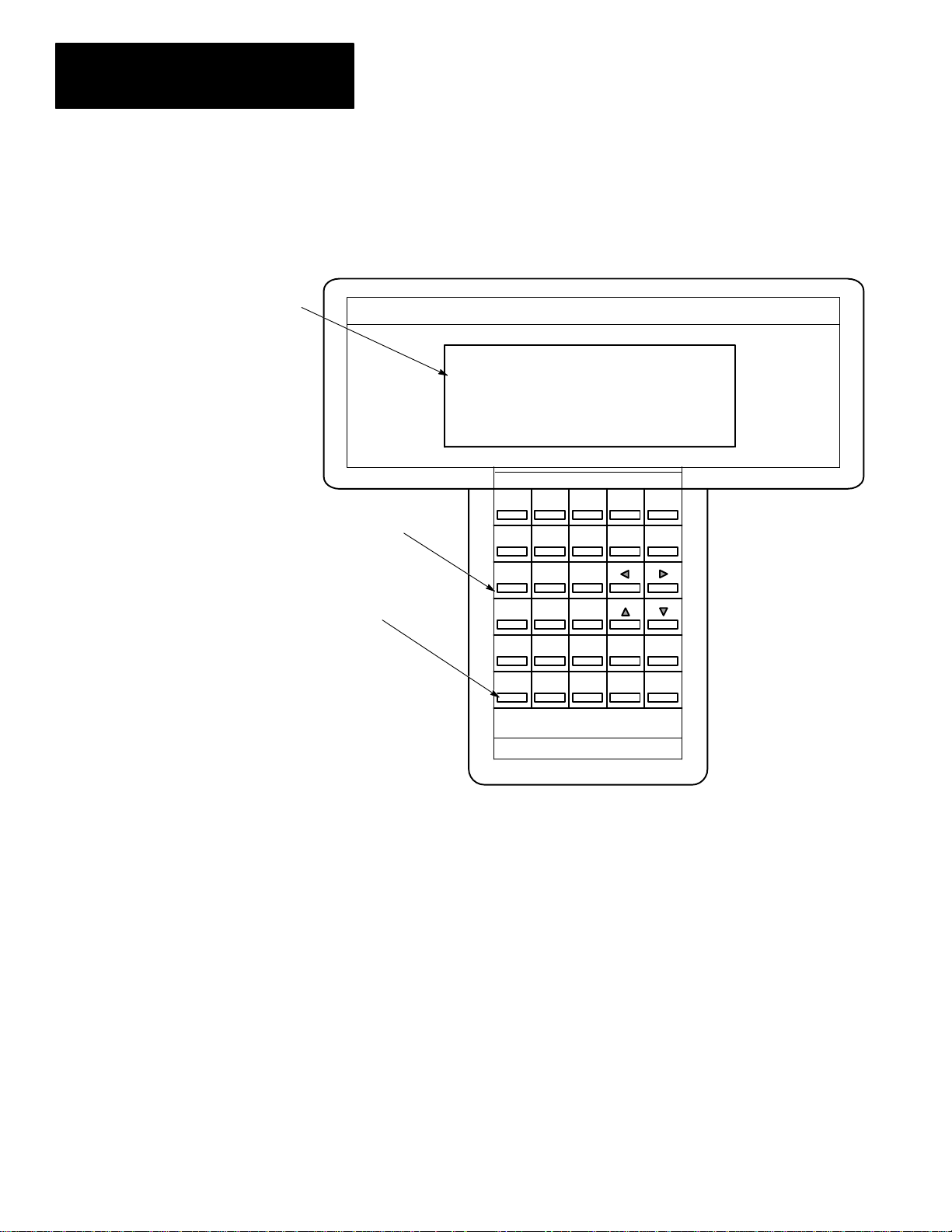
Features, Installation, Powerup
Display Area
The HHT is menu–driven. The display area accommodates 8 lines by 40
characters. You can display up to five rungs of a user program. When
monitoring a program ONLINE, in the Run mode, instructions in a ladder
diagram are intensified to indicate “true” status. A zoom feature is included
to give immediate access to instruction parameters.
SLC 500 PROGRAMMING SOFTWARE Rel. 2.03
Calculator–style,
Color–coded Keyboard
Keys operate with motion and
tactile response.
Allen–Bradley Company Copyright 1990
1747 – PTA1E
All Rights Reserved
PRESS A FUNCTION KEY OFL
SELFTEST TERM PROGMAINT UTILITY
F1 F2 F3 F4 F5
F1 F2
NO
PRE/LEN
ACC/POS
A
7
D
4
T
1
#
0
F3 F4 F5
S
I
U
C
B
9
8
F
E
6
5
M
R
3
2
.
–
:/
SPACE
SHIFT
ESC
ZOOMRUNG
ENTER
1–2
Page 27
Chapter 1
Features, Installation, Powerup
Installing the Memory Pak, Battery, and Communication Cable
The HHT (with communication cable), memory pak, and battery are supplied
separately. Install each as follows:
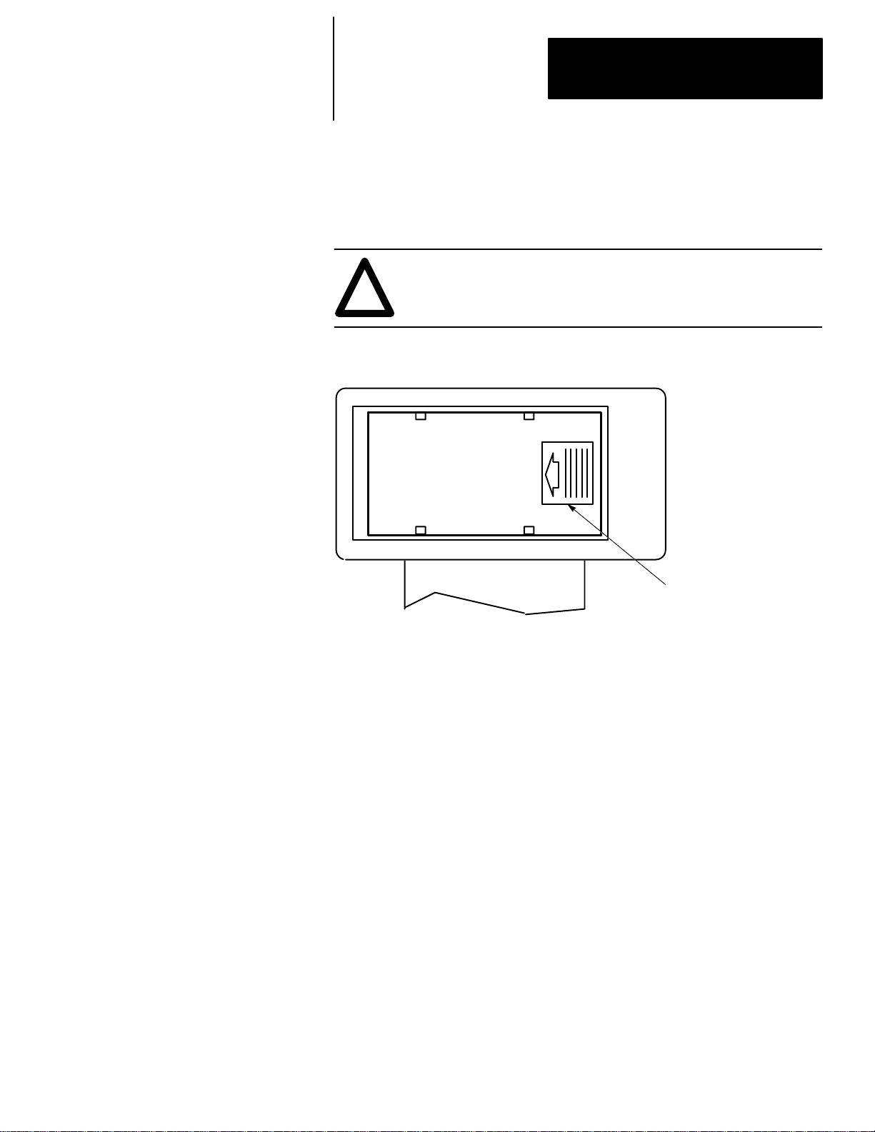
1. Install the memory pak first. The English version is catalog number
1747–PTA1E.
ATTENTION: The memory pak contains CMOS devices. Wear
a grounding strap and use proper grounding procedures to guard
!
against damage to the memory pak from electrostatic discharge.
a. To install the memory pak, remove the cover from the back of the
HHT.
Backside of HHT
Slide cover to the left. Lift off cover.
1–3
Page 28

Chapter 1
Features, Installation, Powerup
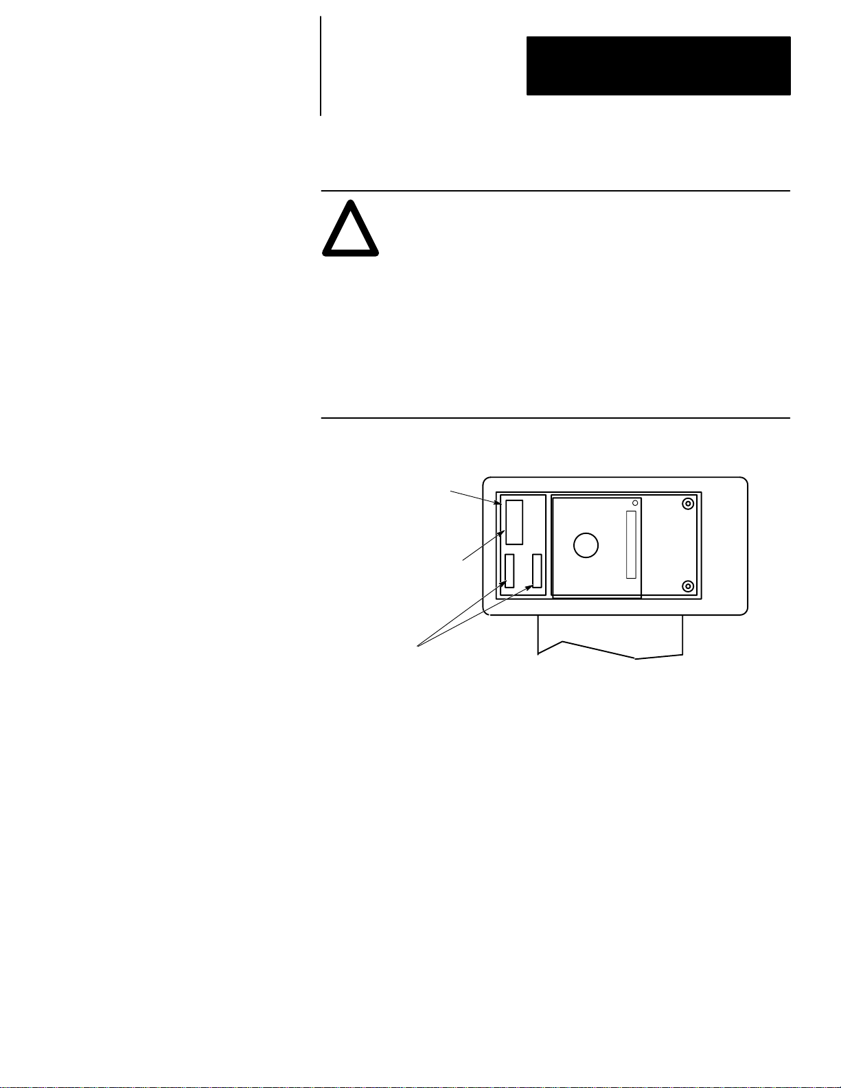
b. Insert the memory pak in its compartment as indicated in the following
figure:
After the memory pak
is in the compartment,
press down on handle
to secure connector in
socket.
.
.
.
.
.
.
.
.
.
.
.
.
.
.
.
.
.
.
.
.
.
.
.
.
.
Backside of HHT
1–4
Page 29
Chapter 1
Features, Installation, Powerup
2. Install the battery, catalog number 1747–BA. The battery compartment is
next to the memory pak compartment.
ATTENTION: The letter B appears flashing on the prompt line
of the HHT display if the battery is not installed correctly or the
!
battery power is low; in addition, each time you power up, the
self–diagnostic is interrupted, and the prompt BATTERY TEST
FAILED appears.
To prevent this from happening, leave the “battery low defeat
jumper” inserted in the battery socket. The HHT is functional,
but your user program is cleared from memory when you
de–energize the HHT. If you do not download the user program
to the processor before you de–energize the HHT, your program
will be lost.
a. Remove the jumper from the battery socket, then connect the battery
as shown in the figure below:
Battery Compartment
Plug battery connector
into socket (red wire up).
Secure battery
between clips.
b. Replace the cover.
.
.
Backside of HHT
1–5
Page 30
Chapter 1
Features, Installation, Powerup
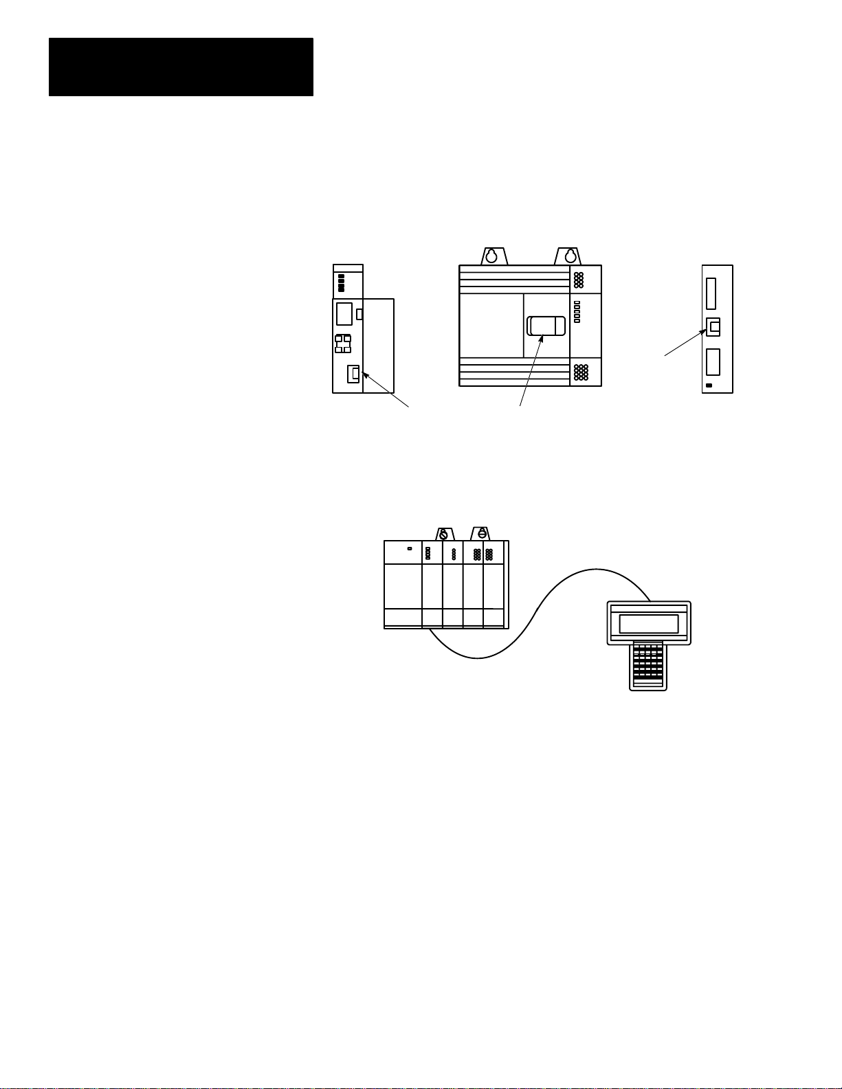
3. Locate the communication port on the SLC 500 controller, or peripheral
port on the 1747–AIC Link Coupler. The figure below shows where it is
located on the different devices:
Processor Module
(Modular Controller)
(Cover Open)
SLC 500 Fixed Controller
(Peripheral Port)
(Communication Port)
Isolated Link
Coupler
The connectors are keyed. Connect one end of the 1747–C10
communication cable to the top of the HHT. The other connector plugs
into the communication port on the SLC 500 controllers or the peripheral
port on the 1747–AIC.
1747–C10 Cable
1–6
SLC Controller
(Modular)
HHT
If you are using a 1747–NP1 wall mount power supply or a 1747–NP2
desktop power supply, plug the communication cable connector into the
socket provided.
Page 31

Chapter 1
Features, Installation, Powerup
HHT Powerup
After you install the memory pak and battery, and plug in the cable, you can
test the operation of the HHT by applying power to the SLC 500 controller
or plugging in the external power supply such as the 1747–NP1 or –NP2.
When the HHT is energized, it performs a series of diagnostic tests. When
the selftest is successfully completed, the following display appears:
SLC 500 PROGRAMMING SOFTWARE Rel. 2.03
Allen–Bradley Company Copyright 1990
PRESS A FUNCTION KEY
SELFTEST TERM PROGMAINT
F1 F2 F3 F4 F5
1747 – PTA1E
All Rights Reserved
OFL
UTILITY
If any of the tests fail, the failure is indicated by the appropriate message on
the display. For a detailed list of HHT messages and error definitions, refer
to appendix A in this manual.
After powerup, you may perform any of five diagnostic tests using the
selftest function. Press
[F1], SELFTEST. The following display appears:
SLC 500 SELFTEST UTILITY
DISPLAY
F1 F2 F3 F4 F5
KEYPAD RAM ROM WTCHDOG
OFL
From this menu, you may choose the test you wish to perform. Press [ESC]
to return to the previous screen.
1–7
Page 32

Chapter 1
Features, Installation, Powerup
HHT Display Format
Display Area
Prompt/Data Entry/Error Area
Menu tree functions
are directly accessible.
Select menu function keys
with [F1] to [F5] keys.
The HHT display format consists of the following:
• display area
• prompt/data entry/error message area
• menu tree functions
The figure below indicates what appears in these areas. To access this
particular screen, press
File Name: 101 Prog Name: 1492
File Name Type Size(Instr)
0 System *
1 Reserved *
2 101 Ladder *
CHG_NAM CRT_FIL EDT_FIL DEL_FIL MEM_MAP >
F1 F2 F3 F4 F5
[F3], PROGMAINT.
Indicates that the HHT is offline.
When online, the node address and
processor mode are shown.
OFL
When the > symbol is present, pressing [ENTER]
toggles additional menu functions.
1–8
Page 33

Chapter 1
Features, Installation, Powerup
The Keyboard
F1 F2
NO
PRE/LEN
ACC/POS
A
7
D
4
T
1
#
0
F3 F4 F5
S
I
U
C
B
9
8
F
E
6
5
M
R
3
2
.
–
:/
SPACE
SHIFT
ESC
ZOOMRUNG
ENTER
This section is intended only as a brief preview of keyboard operation.
Starting in chapter 6, you will become familiar with the keyboard as you are
guided through various programming procedures.
Menu Function Keys (F1, F2, F3, F4, F5)
The top row of purple keys, F1 through F5, are menu function keys. They
select the menu functions shown on the bottom line of the display. Note that
when the > symbol is present, the
functions (if any) at a particular menu level. The
[ENTER] key will toggle additional menu
[ESC] key exits the display
to the previous menu level.
Data Entry Keys
A
B
These blue keys (
7,
for addresses, password, file numbers, and other data. The data you enter
always appears on the prompt/data entry/error message area of the display.
To obtain the upper function of a key, press and release the
then press the desired key.
If you make an error while entering data, press
or use the cursor (arrow) keys and/or the
the error. To complete a data entry, press
[ESC] key to exit the data entry and return to the previous menu level.
C
8,
9...) include numbers, letters, and symbols used
[SHIFT] key,
[ESC] and re–enter the data,
[SPACE] key to locate and correct
[ENTER]. You can also use the
Auto Shift
When you enter an instruction address, the HHT automatically goes to
SHIFT mode to enable you to enter the upper function of a key without first
pressing the
bottom right hand corner of the display.
ZOOM on XIC
NAME: EXAMINE IF CLOSED
BIT ADDR:
ENTER BIT ADDR:
The data you enter
appears here,
at the cursor location.
[SHIFT] key. This mode is indicated by a small arrow in the
] [
2.6.0.0.*
Indicates that the HHT is in
SHIFT mode (e.g., to enter
the letter “I” you do not
have to first press SHIFT).
F1 F2 F3 F4 F5
1–9
Page 34

Chapter 1
Features, Installation, Powerup
Cursor Keys
,,,
Use the four arrow keys to:
• change or modify instruction addresses
• locate and correct data entry errors (either type over or use the [SPACE]
key)
• move the cursor left, right, up, and down in a ladder program (rungs not
shown on the HHT display automatically scroll into view as you move the
cursor up [or down] in the program)
• scroll through controller and I/O configuration selections
• scroll through program file directories
• scroll through active node addresses
• scroll through the elements and bits of individual data files
The keys move
the cursor left and right
between the items of the
address.
ZOOM on OTE –( )– 2.1.1.0.2
NAME: OUTPUT ENERGIZE
BIT ADDR:O0:2.0/7
ENTER BIT ADDR: O0:2.0/7
EDT_DAT ACCEPT
F1 F2 F3 F4 F5
The keys
move the cursor left, right,
up, and down in a ladder
diagram.
XIC:I1:2.0/2 NO FORCE 2.4.0.0.1
] [
] [
OFL
INS RNG MOD RNG SEARCH DEL RNG UND RNG >
F1 F2 F3 F4 F5
( )
( )
( )
( )
( )
1–10
Page 35

Chapter 1
Features, Installation, Powerup
The keys scroll
through the I/O module
choices in this display.
Similarly, these keys scroll
through rack and CPU
choices in the appropriate
displays.
The keys scroll
through user program
files.
The keys scroll
through active node
addresses.
Rack 1 = 1746–A4 4–SLOT RACK
Rack 2 = NONE
Rack 3 = NONE
Slot 0 = 1747–L511 CPU–1K USER MEMORY
Slot 1 = 1746–IA4 4–INPUT 100/120 VAC
Slot 1 = 1746–IA4 4–INPUT 100/120 VAC
F1 F2 F3 F4 F5
File Name: Prog Name:2A
File Name Type Size(Instr)
0 System 217
1 Reserved 0
2 Ladder 30
OFL
CHG NAM CRT FIL EDT FIL DEL FIL MEM MAP >
F1 F2 F3 F4 F5
Node Addr. Device Max Addr./Owner
0 APS (31)
1 TERMINAL (31)
*** 2 5/02 (31) ***
3 500–20 (31)
Node Addr: 0 Baud Rate: 19200
OFL
DIAGNSTC ATTACH NODE CFG OWNER
F1 F2 F3 F4 F5
The keys
move the cursor left, right,
up and down in a data file
display.
Address 15 data 0
B3:0 0010 0011 0100 1111
B3:1 1000 0010 0000 0000
B3:2 0000 0000 1110 0000
B3:3 0000 0000 0100 0000
B3:4 0101 1101 0100 1000
B3/31 = 1 RUN
ADDRESS NEXT FL PREV FL NEXT PG PREV PG
F1 F2 F3 F4 F5
1–11
Page 36

Chapter 1
Features, Installation, Powerup
ZOOM and RUNG Keys
The [ZOOM] key brings up a display that shows the parameters of an
instruction.
The
[RUNG] key moves the cursor to a particular rung. Using this key saves
time when you have a long ladder diagram. When you press
prompted for the rung number that you want to edit or monitor. Enter the
rung number and press
[ENTER], the cursor moves to the selected rung and
the rung appears at the top of the display.
[RUNG], you are
Press [RUNG][6][ENTER].
The cursor moves from the Timer
rung to the left power rail of rung 6.
TON:T4:2 2.2.0.0.2
] [
] [
] [
] [
] [
OFL
INS RNG MOD RNG SEARCH DEL RNG UND RNG >
F1 F2 F3 F4 F5
ZOOM on TON –(TON)– 2.2.0.0.2
NAME: TIMER ON DELAY
TIMER: T4:2 TIME BASE .01 SEC
PRESET: 20
ACCUM: 0
EDT_DAT
F1 F2 F3 F4 F5
TON:T4:2 2.6.0.0.*
] [
] [
] [
] [
] [
OFL
INS RNG MOD RNG SEARCH DEL RNG UND RNG >
F1 F2 F3 F4 F5
(TON)
( )
( )
( )
( )
(TON)
( )
( )
( )
( )
Press the [ZOOM] key
with the cursor on an
instruction. The Zoom
display shows the
instruction parameters.
Exit the Zoom display by
pressing [ESC] or
[ZOOM].
1–12
Page 37

Chapter
2
The Menu Tree
This chapter guides you through the HHT display menu tree. It is intended
as an overview. For a more detailed introduction to ladder programming,
refer to The Getting Started Guide for HHT, catalog number 1747–NM009.
The abbreviated function and instruction mnemonic keys you encounter in
this manual and on the HHT displays are explained at the end of this chapter.
Using the HHT Menu
Before you begin using the HHT to develop a user program or communicate
online, you should be familiar with the following:
Progressing through Menu Displays
To progress through the HHT menu displays, press the desired function key.
When that display appears, press the next appropriate function key, and so
on.
1. For example, to clear the HHT memory, start from the Main menu.
SLC 500 PROGRAMMING SOFTWARE Rel. 2.03
Allen–Bradley Company Copyright 1990
PRESS A FUNCTION KEY
SELFTEST TERM PROGMAINT
F1 F2 F3 F4 F5
2. Press [F3], PROGMAINT. The following menu is displayed:
File Name: 101 Prog Name: 1492
File Name Type Size(Instr)
0 System 217
1 Reserved 0
2 101 Ladder 465
1747 – PTA1E
All Rights Reserved
OFL
UTILITY
CHG_NAM CRT_FIL EDT_FIL DEL_FIL MEM_MAP >
OFL
F1 F2 F3 F4 F5
2–1
Page 38

Chapter 2
The Menu Tree
The ENTER Key
1. Because the > symbol appears in the lower right hand corner of the
display, press
File Name: 101 Prog Name: 1492
File Name Type Size(Instr)
0 System 217
1 Reserved 0
2 101 Ladder 465
[ENTER] to display additional menu functions.
EDT_DAT SEL_PRO EDT_I/O CLR_MEM >
F1 F2 F3 F4 F5
OFL
2. Press [F4], CLR_MEM to clear the HHT memory. You are asked to
confirm:
File Name: 101 Prog Name: 1492
File Name Type Size(Instr)
0 System 217
1 Reserved 0
2 101 Ladder 465
ARE YOU SURE?
YES NO >
F1 F2 F3 F4 F5
OFL
3. Press [F2], YES. This deletes the current program in the HHT. After
you confirm, the display returns to the previous menu.
File Name: Prog Name: Default
File Name Type Size(Instr)
0 System
1 Reserved
2 Ladder
EDT_DAT SEL_PRO EDT_I/O CLR_MEM >
F1 F2 F3 F4 F5
OFL
2–2
The ESCAPE Key
Use [ESC] to exit a menu and move to the previous one.
1. Press
[ESC] to return to the Main menu.
SLC 500 PROGRAMMING SOFTWARE Rel. 2.03
Allen–Bradley Company Copyright 1990
PRESS A FUNCTION KEY
SELFTEST TERM PROGMAINT
F1 F2 F3 F4 F5
1747 – PTA1E
All Rights Reserved
OFL
UTILITY
Page 39

Chapter 2
The Menu Tree
The Main Menu
Main Menu Functions
After going through diagnostic tests at startup/powerup, the HHT displays
the Main menu. It consists of the following function keys:
• Selftest
• Terminal
• Program Maintenance
• Utility
The display appears as follows:
SLC 500 PROGRAMMING SOFTWARE Rel. 2.03
Allen–Bradley Company Copyright 1990
PRESS A FUNCTION KEY
SELFTEST TERM PROGMAINT
F1 F2 F3 F4 F5
1747 – PTA1E
All Rights Reserved
OFL
UTILITY
Some of the procedures you may perform from the Main menu are:
SELFTEST,
[F1]
Allows you to test the following components of the HHT:
• display
• keypad
• random access memory
• read only memory
• internal watchdog timer
TERMINAL,
[F2]
Allows you to:
• configure the HHT for IMC 110 mode (when attached to a
1746–HS module)
• monitor and debug MML programs
PROGRAM MAINTENANCE,
Allows you to:
[F3]
• name programs and program files
• create, delete, and edit program files
• create and delete data files
• edit data files
• select processors and configure the I/O
• clear HHT memory
2–3
Page 40

Chapter 2
The Menu Tree
UTILITY, [F5]
Allows you to:
• attach online to a processor
– upload and download programs between the processor and HHT
– change processor mode
– transfer processor memory between RAM and EEPROM
– force inputs and outputs
• access network diagnostic functions
• create or delete processor passwords
• clear processor memory
• monitor the ladder diagram while the processor is in Run mode
The Menu Tree
The figures that follow, graphically guide you through the HHT menus and
sub–menus.
Main Menu
F1
SELFTEST
F2 TERM
F3 PROGMAINT
F5 UTILITY
DISPLAYF1
KEYPADF2
RAMF3
ROMF4
WTCHDOGF5
DSTRUCTF2
NONDESTF4
Refer to page 2–6.
Refer to page 2–7 to 2–10.
2–4
Main Menu Function Key Use For
SELFTEST HHT unit diagnostics
TERM terminal mode for IMC 110
PROGMAINT program development and editing
UTILITY processor/network communications and online monitoring
Page 41

Main Menu – Program Maintenance [F3]
Chapter 2
The Menu Tree
PROGMAINTF3 CHG_NAMF1
ENTER
PROGRAMF2
CRT_FILF2
EDT_FILF3
ENTER
DEL_FILF4
MEM_MAPF5
EDT_DATF1
SEL_PROF2
EDT_I/OF3
CLR_MEMF4
FILEF4
INS_RNG_F1
MOD_RNGF2
SEARCHF3
DEL_RNGF4
UND_RNGF5
EDT_DATF1
SAVE_CTF4
SAVE_EXF5
CRT_DTF1
DEL_DTF2
NEXT_PGF3
PREV_PGF4
PRG_SIZEF5
ADDRESSF1
NEXT_FLF2
PREV_FLF3
NEXT_PGF4
PREV_PGF5
TYPEF1
SERIESF3
MOD_RCKF1
MOD_SLTF2
DEL_SLTF3
UND_SLTF4
ADV_SETF5 INT_SBRF1
CUR–INSF1
CUR–OPDF2
NEW–INSF3
UPF4
FORCEF5
ADDRESSF1
NEXT_FLF2
PREV_FLF3
NEXT_PGF4
PREV_PGF5
RACK 1F1
RACK 2F2
RACK 3F3
OTHERF3
MOD_SETF2 BINF1
CFG_SIZF3
ADV_SIZF4
ENTER
INS_INSTF1
BRANCHF2
MOD_INSTF3
ACP_RNGF5
DEL_INSTF2
UND_INSTF4
EXT_UPF1
EXT_DWNF2
APP_BRF3
INS_BRF4
DEL_BRF5
See next
page.
Legend
DECF2
HEX/BCDF3
NEXT_PGF4
PREV_PGF5
Modular controllers only
SLC 5/02 only
Toggle operation
•
Enter file number
May have to select
*
node first
2–5
Page 42

Chapter 2
The Menu Tree
Program Maintenance [F3] – Ladder Editing
See previous
page.
ENTER
BITF1
TMR/CNTF2 TONF1
I/O_MSGF3 IIMF1
COMPAREF4 LIMF1
MEQF3
EQUF4
NEQF5
ENTER
LESF1
GRTF2
LEQF3
GEQF4
OTHERSF5
CPT/MTHF5
MOV/LOGF1 MOVF1
FILEF2
SFT/SEQF3
CONTROLF4
JMPF1
LBLF2
JSRF3
RETF4
MCRF5
ENTER
IOMF2
MSGF3
IIEF4
IIDF5
RPIF1
REFF3
SVCF4
OTHERSF5
BSLF1
BSRF2
SQCF3
SQLF4
SQOF5
ENTER
TOFF2
RTOF3
CTUF4
CTDF5
RESF1
HSCF2
OTHERSF5
COPF1
FLLF2
ENTER
SBRF1
INTF2
STEF3
STSF4
STDF5
ENTER
SUSF3
TNDF4
OTHERSF5
ENTER
ENTER
FFLF1
FFUF2
LFLF3
LFUF4
OTHERSF5
OTHERSF5
ENTER
MVMF2
ANDF3
ORF4
XORF5
NOTF1
OTHERSF5
–] [–F1
–] / [–F2
–( )–F3
–( L )–F4
–( U )–F5
OSRF1
OTHERSF5
ADDF1
SUBF2
MULF3
DIVF4
DDVF5
ENTER
NEGF1
CLRF2
SQRF3
TODF4
FRDF5
ENTER
DCDF2
SCLF3
PIDF4
OTHERSF5
2–6
Page 43

Main Menu – Utility [F5], Default Program in Processor (First Time)
Chapter 2
The Menu Tree
UTILITYF5
ONLINEF1
WHOF2
PASSWRDF3
CLR_MEMF5
DIAGNSTCF1
*
ATTACHF3
NODE_CFGF4
OWNERF5
ENTF1
REMF2
ENT_MASF3
REM_MASF4
NODEF1
NETWORKF5 RESETF5
OFFLINEF1
DWNLOADF2
CLR_PRCF3
MEM_PRCF4
CHG_ADRF1
MAX_ADRF2
BAUDF3
SET_OWNRF1
CLR_OWNRF5
19200F1
9600F2
2400F3
1200F4
Main Menu – Utility [F5], Default Program in Processor (If Previously Attached to that Processor)
UTILITYF5
ONLINEF1
WHOF2
PASSWRDF3
CLR_MEMF5
OFFLINEF1
DWNLOADF2
CLR_PRCF3
MEM_PRCF4
DIAGNSTCF1
*
ATTACHF3
NODE_CFGF4
OWNERF2
ENTF1
REMF2
ENT_MASF3
REM_MASF4
NODEF1
NETWORKF5 RESETF5
OFFLINEF1
DWNLOADF2
CLR_PRCF3
MEM_PRCF4
CHG_ADRF1
MAX_ADRF2
BAUDF3
SET_OWNRF1
CLR_OWNRF5
19200F1
9600F2
2400F3
1200F4
Legend
Modular controllers only
SLC 5/02 only
Toggle operation
•
Enter file number
May have to select
*
node first
2–7
Page 44

Chapter 2
The Menu Tree
Main Menu – Utility [F5], Processor Program Does Not Equal HHT Program (First Time)
UTILITYF5 ONLINEF1
WHOF2
PASSWRDF3
CLR_MEMF5
DIAGNSTCF1
*
ATTACHF3
NODE_CFGF4
OWNERF5
ENTF1
REMF2
ENT_MASF3
REM_MASF4
NODEF1
NETWORKF5 RESETF5
OFFLINEF1
UPLOADF2
DWNLOADF3
MODEF4
CLR_PRCF5
CHG_ADRF1
MAX_ADRF2
BAUDF3
SET_OWNRF1
CLR_OWNRF5
RUNF1
TESTF3 CONTF2
F1 19200
9600
F2
2400
F3
1200
F4
SINGLEF4PROGRAMF5
Main Menu – Utility [F5], Processor Program Does Not Equal HHT Program (If Previously Attached to that Processor)
UTILITYF5 ONLINEF1
WHOF2
PASSWRDF3
CLR_MEMF5
OFFLINEF1
UPLOADF2
DWNLOADF3
MODEF4
CLR_PRCF5
DIAGNSTCF1
*
ATTACHF3
NODE_CFGF4
OWNERF5
ENTF1
REMF2
ENT_MASF3
REM_MASF4
RUNF1
TESTF3 CONTF2
•
•
•
NODEF1
NETWORKF5 RESETF5
OFFLINEF1
UPLOADF2
DWNLOADF3
MODEF4
CLR_PRCF5
CHG_ADRF1
MAX_ADRF2
BAUDF3
SET_OWNRF1
CLR_OWNRF5
SINGLEF4PROGRAMF5
RUNF1
TESTF3 CONTF2
F1 19200
9600
F2
2400
F3
1200
F4
SINGLEF4PROGRAMF5
2–8
Page 45

Chapter 2
The Menu Tree
Main Menu – Utility [F5], Processor Program Equals HHT Program (First Time)
UTILITYF5
ONLINEF1
WHOF2
PASSWRDF3
CLR_MEMF5
DIAGNSTCF1
ATTACHF3
NODEF1
NETWORKF5 RESETF5
OFFLINEF1
UPLOADF2
DWNLOADF3
MODEF4
CLR_PROCF5
RUNF1
TESTF3 CONTF2
ENTER
PASSWRDF1
XFERMEMF3
EDT_DATF4
MONITORF5
NODE_CFGF4
OWNERF5
ENTF1
REMF2
ENT_MASF3
REM_MASF4
CHG_ADRF1
MAX_ADRF2
BAUDF3
SET_OWNRF1
CLR_OWNRF5
ENTF1
REMF2
ENT_MASF3
REM_MASF4
MEM_PRCF2
PRC_MEMF4
ADDRESSF1
NEXT_FLF2
PREV_FLF3
NEXT_PGF4
PREV_PGF5
MODEF1
FORCEF2
EDT_DATF3
SEARCHF4
F1 19200
9600
F2
F3
2400
1200
F4
SINGLEF4PROGRAMF5
RUNF1
TESTF3 CONTF2
ONF1
OFFF2
REMF3
REM_ALLF4
ENABLEF5
ADDRESSF1
NEXT_FLF2
PREV_FLF3
NEXT_PGF4
PREV_PGF5
CUR–INSF1
CUR–OPDF2
NEW–INSF3
UPF4
FORCEF5
•
•
Legend
Modular controllers only
SLC 5/02 only
Toggle operation
•
Enter file number
May have to select
*
node first
SINGLEF4PROGRAMF5
2–9
Page 46

Chapter 2
The Menu Tree
Main Menu – Utility [F5], Processor Program Equals the HHT Program (If Previously Attached to that Processor)
UTILITYF5 ONLINEF1
OFFLINEF1
UPLOADF2
DWNLOADF3
MODEF4
CLR_PROCF5
ENTER
PASSWRDF1
XFERMEMF3
EDT_DATF4
MONITORF5
WHOF2
PASSWRDF3
CLR_MEMF5
DIAGNSTCF1
*
ATTACHF3
NODE_CFGF4
OWNERF5 SET_OWNRF1
ENTF1
REMF2
ENT_MASF3
REM_MASF4
CHG_ADRF1
MAX_ADRF2
BAUDF3 19200F1
CLR_OWNRF5
NODEF1
NETWORKF5 RESETF5
9600F2
2400F3
1200F4
RUNF1
TESTF3 CONTF2
ENTF1
REMF2
ENT_MASF3
REM_MASF4
MEM_PRCF2
PRC_MEMF4
ADDRESSF1
NEXT_FLF2
PREV_FLF3
NEXT_PGF4
PREV_PGF5
MODEF1
FORCEF2
EDT_DATF3
SEARCHF4
SINGLEF4PROGRAMF5
Legend
Modular controllers only
SLC 5/02 only
Toggle operation
•
Enter file number
Select node first
*
RUNF1
TESTF3
PROGRAMF5
ONF1
OFFF2
REMF3
REM_ALLF4
ENABLEF5
ADDRESSF1
NEXT_FLF2
PREV_FLF3
NEXT_PGF4
PREV_PGF5
CUR–INSF1
CUR–OPDF2
NEW–INSF3
UPF4
FORCEF5
•
•
CONTF2
SINGLEF4
2–10
Page 47

Chapter 2
The Menu Tree
HHT Function Keys and Instruction Mnemonics
The following table provides a listing of the abbreviated function keys and
their meanings. The next table provides a list of instruction mnemonics.
Function Keys
Abbreviation Meaning
ACCUM accumulator value
ACP_RNG accept rung
ADDR address
ADV_SET advanced setup
ADV_SIZ advanced size
APP_BR append branch
B battery
BIN binary number
CAN_ED cancel edit
CAN_RNG cancel rung
CFG_SIZ configure size
CHG_ADR change node address
CHG_NAM change name
CLR_MEM clear memory
CLR_OWNR clear ownership
CLR_PRC clear processor
CONT continuous
CPT/MTH compute/math
CRT_DT create data
CRT_FIL create file
CSN continuous scan
CUR–INS current instruction
CUR–OPD current operand
DEC decimal number
DEL_BR delete branch
DEL_DT delete data
DEL_FIL delete file
DEL_INST delete instruction
DEL_RNG delete rung
DEL_SLT delete slot
DIAGNSTC diagnostic
DWNLOAD download
2–11
Page 48

Chapter 2
The Menu Tree
Abbreviation
EDT_DAT edit data
EDT_FIL edit file
EDT_I/O edit I/O
ENT enter
ENT_MAS enter master
EXEC_FILE executable files
EXT_DWN extend down
EXT_UP extend up
F force
FILEPRT file protection
FLT fault
FUTACC future access
HEX/BCD hexadecimal/binary coded decimal number
INDXCHK index across files
INS_BR insert branch
INS_INST insert instruction
INS_RNG insert rung
INT_SBR interrupt subroutine
I/O_MSG I/O message
MAX_ADR maximum node address
MEM_MAP memory map
MEM_PRC memory module to processor
MEM_SIZ memory size
MOD_INST modify instruction
MOD_RCK modify rack
MOD_RNG modify rung
MOD_SET modify setup
MOD_SLT modify slot
MOR_CPT more compute
MOV/LOG move/logic
NEW–INS new instruction
NEW_PRG new program
NEXT_FL next file
NEXT_PG next page
NODE_CFG node configuration
OFL offline
OTHERS other instruction choices
Meaning
2–12
Page 49

Chapter 2
The Menu Tree
Abbreviation
PASSWRD password
PRC_MEM processor to memory module
PREV_FL previous file
PREV_PG previous page
PRG program
PRG_SIZE program size
PROGMAINT program maintenance
RLY relay
REM remove
REM_ALL remove all
REM_MAS remove master
SAVE_CT save and continue
SAVE_EX save and exit
SEL_PRO select processor
SET_OWNR set ownership
SFT/SEQ shift/sequencer
SNK sink
SRC source
SSN single scan
TERM terminal
TMR/CNT timer/counter
TRANS transistor
TRI triac
TSTRUNG test single rung
UND_INST undelete instruction
UND_RNG undelete rung
UND_SLT undelete slot
WTCHDOG watchdog
XFERMEM transfer memory
Meaning
2–13
Page 50

Chapter 2
The Menu Tree
Instruction Mnemonics
Mnemonic Instruction
ADD add
AND and
BSL bit shift left
BSR bit shift right
CLR clear
COP copy file
CTD count down
CTU count up
DCD decode 4 to 1 of 16
DDV double divide
DIV divide
EQU equal
FFL
FFU FIFO unload
FLL file fill
FRD convert from BCD
GEQ greater than or equal to
GRT greater than
HSC high–speed counter
IID I/O interrupt disable
IIE I/O interrupt enable
IIM immediate input with mask
INT interrupt subroutine
IOM immediate output with mask
JMP jump to label
JSR jump to subroutine
LBL label
LEQ less than or equal to
LES less than
LFL
LFU LIFO unload
LIM limit test
MCR master control reset
MEQ masked comparison for equal
MOV move
MSG message
MUL multiply
MVM masked move
FIFO load
LIFO load
2–14
Page 51

Chapter 2
The Menu Tree
Mnemonic
NEG negate
NEQ not equal
NOT not
OR or
OSR one–shot rising
OTE output energize
OTL output latch
OTU output unlatch
PID proportional integral derivative
REF I/O refresh
RES reset
RET return from subroutine
RPI reset pending I/O interrupt
RTO retentive on–delay timer
SBR subroutine
SCL scale data
SQC sequencer compare
SQL sequencer load
SQO sequencer output
SQR square root
STD STI disable
STE STI enable
STS STI start immediately
SUB subtract
SUS suspend
SVC service communications
TND temporary end
TOD convert to BCD
TOF timer off–delay
TON timer on–delay
XIC examine if closed
XIO examine if open
XOR exclusive or
Instruction
2–15
Page 52

Page 53

Chapter
3
Understanding File Organization
This chapter:
• defines program, program files, and data files
• indicates how programs are stored and transferred
• covers the use of EEPROMs and UVPROMs for program backup
Program, Program Files, and Data Files
As explained in the following sections, the program can reside in:
• the Hand–Held Terminal
• an SLC 500 processor
• a memory module
• the APS terminal
Notes on terminology: The term program used in Hand-Held Terminal
(HHT) displays is equivalent to the term processor file used in APS software
displays. These terms mean the collective program files and data files
created under a particular program or processor file.
Most of the operations you perform with the HHT involve the program and
the two components created with it: program files and data files.
Program
Program Files Data Files
3–1
Page 54

Chapter 3
Understanding File Organization
Program
A program is the collective program files and data files of a particular user
program. It contains all the instructions, data, and configuration information
pertaining to that user program. The HHT allows only numbers and certain
letters available on the keyboard to be entered for a program name.
The program is a transferable unit. It can be located in the Hand-Held
Terminal (or in the APS programming terminal); it can be transferred to/from
an SLC 500, 5/01, or 5/02 processor, or to/from a memory module located in
the processor.
Program 01 Program 02 Program 03
HHT SLC 500 Processor Memory Module
Upload
Download
HHT SLC 500 Processor
The HHT and each CPU hold one program at a time. A program is created
in the offline mode using your HHT. You first configure your controller,
then create your user program. When you have completed and saved your
program, you download it to the processor RAM memory for online
operation. (See page 3–3 for more information on downloading.) You may
also keep a back–up of your program in the EEPROM memory module
located in the processor.
Program Files
Program files contain controller information, the main control program, and
any subroutine programs. The first three program files are required for each
program. These are:
• System Program (file 0)–This file is always included and contains
various system related information and user-programmed information
such as processor type, I/O configuration, program name and password.
• Reserved (file 1)– This file is always included and is reserved for internal
controller use.
• Main Ladder Program (file 2)–This file is always included and contains
user-programmed instructions defining how the controller is to operate.
• Subroutine Ladder Program (files 3 – 255)–These are user-created and
activated according to subroutine instructions residing in the main ladder
program file.
3–2
Page 55

Chapter 3
Understanding File Organization
Data Files
Data files contain the data associated with the program files. Each program
can contain up to 256 data files. These files are organized by the type of data
they contain. Each piece of data in each of these files has an address
associated with it that identifies it for use in the program file. For example,
an input point has an address that represents its location in the input data file.
Likewise, a timer in the timer data file has an address associated with it that
allows you to represent it in the program file.
The first 9 data files (0 – 8) have default types. You designate the remainder
of the files (9 – 255) as needed. The default types are:
• Output (file 0) – This file stores the status of the output terminals or
output information written to speciality modules in the system.
• Input (file 1) – This file stores the status of the input terminals or input
information read from the speciality modules in the system.
• Status (file 2) – This file stores controller operation information. This
file is useful for troubleshooting controller and program operation.
• Bit (file 3) – This file is used for internal relay logic storage.
• Timer (file 4) – This file stores the timer accumulated and preset values
and status bits.
• Counter (file 5) – This file stores the counter accumulated and preset
values and the status bits.
• Control (file 6) – This file stores the length, pointer position, and status
bits for specific instructions such as shift registers and sequencers.
• Integer (file 7) – This file is used to store numeric values or bit
information.
• Reserved (file 8) – This file is not accessible to the user.
• User–Defined (file 9 – 255) – These files are user–defined as Bit, Timer,
Counter, Control and/or Integer data storage. In addition, file 9 is
specifically available as a Communication Interface File for
communication with non–SLC 500 devices on a DH–485 network.
Downloading Programs
When you have completed your program, it is necessary to transfer it to the
SLC 500 processor in order to run the program. You do this by attaching
your HHT to the processor and using the download function to transfer the
program into the processor RAM. When downloading, you must take the
processor out of the Run mode.
HHT
RAM RAM
1000
Download
PROCESSOR
1000
3–3
Page 56

Chapter 3
Understanding File Organization
Uploading Programs
When you need to modify a program, it may be necessary to upload the
program from an SLC 500 processor to the HHT. If the original HHT
program is not current or the HHT has been attached to a different processor,
uploading is necessary. Use the upload function to do this. When you are
uploading, you can leave the processor in the Run mode.
HHT
RAM RAM
1000
Upload
PROCESSOR
1000
Using EEPROM and UVPROM Memory Modules for Program Backup
An EEPROM or UVPROM memory module can be inserted in SLC 500
controllers. You can use the HHT to transfer a copy of the program in
processor RAM to an EEPROM memory module. UVPROM memory
modules cannot be programmed by a processor
PROM burner.) You can also transfer a program from an EEPROM or
UVPROM memory module to the processor’s RAM memory.
14–1 for more information on using EEPROMs and UVPROMs.
PROCESSOR
RAM
1000
Processor
to Memory
Memory to
Processor
MEMORY
MODULE
1000
. (You need an external
Refer to page
3–4
Page 57

Chapter
4
Data File Organization and Addressing
This chapter discusses the following topics:
• data file organization and addressing
• indexed addressing (SLC 5/02 processors)
• file instructions (using the file indicator #)
• creating and deleting data
• program constants
• M0-M1 files, G files (SLC 5/02 processors with specialty I/O modules)
Data File Organization
Data Files residing in the processor memory
0
1
2
3
4
5
6
7
8
9
10–255
Note: Data file 9 can be used for network transfer on the
DH-485 network. Non-SLC 500 devices are able to read
and write to this file. Data file 9 can be used as an
ordinary data file if the processor is not on a network.
Designate this file as Integer or Bit when using the
network transfer function.
This file is also called “Common Interface File 485CIF” or
“PLC–2 compatibility file.”
Bit, Timer, Counter,
Control, or Integer,
assigned as needed
Output image
Input image
Status
Bit
Timer
Counter
Control
Integer
Reserved
See Note below
Data files contain the status information associated with external I/O and all
other instructions you use in your main and subroutine ladder program files.
In addition, these files store information concerning processor operation.
You can also use the files to store “recipes” and lookup tables if needed.
Data Files associated with Specialty I/O modules (SLC 5/02
processors)
M0 and M1 files
These data files reside in the memory of the specialty I/O
module. Their function depends on the particular specialty I/O
module.
In most cases, you can address these files in your ladder
program.
G files
These data files are the software equivalent of DIP switches.
G files are accessed and edited offline under the I/O
Configuration function. The information is passed on to the
specialty I/O module when you enter the Run or Test mode.
4–1
Page 58

Chapter 4
Data File Organization and Addressing
Data File Types
For the purposes of addressing, each data file type is identified by a letter
(identifier) and a file number.
File numbers 0 through 7 are the default files, created for you. If you need
additional storage, you can create files by specifying the appropriate
identifier and a file number from 9 to 255. This applies to Bit, Timer,
Counter, Control, and Integer files only. Refer to the tables below:
Data file types, identifiers, and numbers
Addressing Data Files
File
Type
Output
Input
Status
Bit
Timer
Counter
Control
Integer
Identifier
O
I
S
B
T
C
R
N
File
Number
0
1
2
3
4
5
6
7
User–Defined Files
File
Type
Bit
Timer
Counter
Control
Integer
Identifier
B
T
C
R
N
File
Number
9–255
Data files contain elements. As shown below, some data files have 1-word
elements, some have 3-word elements. You will be addressing elements,
words, and bits.
Output and Input files have 1-word elements, with each element specified
by slot and word number:
0123456789101112131415
Element
O:1.0
O:1.1
O:1.2
4–2
Elements in Timer, Counter, and Control files consist of 3 words:
0123456789101112131415
Word
0
1
2
Status, Bit, and Integer files have 1-word elements:
0123456789101112131415
Addresses are made up of alpha-numeric characters separated by delimiters.
Delimiters include the colon, slash, and period.
Page 59

Chapter 4
Data File Organization and Addressing
Typical element, word, and bit addresses are shown below:
File
Type
File
Number
N7:15
Element
Delimiter
Element
File
Type
File
Number
Element
T4:7.ACC
Element
Delimiter
Word
Delimiter
Word
File
Type
Element
Delimiter
File
Number
B3:64/15
An element address A word address A bit address
The address format varies, depending on the file type. This is explained in
the following sections, beginning with file 2, the status file, and following
with files 0, 1, 3, 4, 5, 6, and 7.
Data File 2 – Status
The status file is explained in chapter 27. You can address various bits and
words as follows:
Element
Bit
Bit
Delimiter
Format Explanation
S Status file
: Element delimiter
S:e/b e Element
number
/ Bit delimiter
b Bit number Bit location within the element. Ranges from 0 to 15.
Examples:
S:1/15 Element 1, bit 15. This is the “first pass” bit, which you can use to
S:3 Element 3. The lower byte of this element is the current scan time.
Ranges from 0 to 15 in a SLC 5/01 or fixed controller, 0-32
in a SLC 5/02. These are 1-word elements. 16 bits per
element.
initialize instructions in your program.
The upper byte is the watchdog scan time.
4–3
Page 60

Chapter 4
Data File Organization and Addressing
Data Files 0 and 1 – Outputs and Inputs
Bits in file 0 are used to represent external outputs. Bits in file 1 are used to
represent external inputs. In most cases, a single 16-bit word in these files
will correspond to a slot location in your controller, with bit numbers
corresponding to input or output terminal numbers. Unused bits of the word
are not available for use.
I/O Addressing for a Controller with Fixed I/O: In the figure below, a
fixed I/O controller has 24 inputs and 16 outputs. An expansion rack has
been added. Slot 1 of the rack contains a module having 6 inputs and 6
outputs. Slot 2 contains a module having 8 outputs.
The figure shows how these outputs and inputs are arranged in data files 0
and 1. For these files, the element size is always 1 word.
The table on the following page explains the addressing format for outputs
and inputs. Note that the format specifies
word number. When you are dealing with file instructions, refer to the
element as
e.s (slot and word), taken together.
e as the slot number and s as the
Slot Numbers
Fixed I/O
Controller
012
I/O I/O I/O
Expansion
rack
Slot 0 outputs (0–15)
Slot 1 outputs (0–5)
Slot 2 outputs (0–7)
Slot 0 inputs (0–15)
Slot 0 inputs (16–23)
Slot 1 inputs (0–5)
Slot Inputs Outputs
24
0
6
1
None
2
Data File 0 – Output Image
INVALID
INVALID
Data File 1 – Input Image
X
INVALID
INVALID
See Addressing “Examples,” next page.X
16
6
8
0123456789101112131415
X
X
X
X
O:0
O:1
O:2
0123456789101112131415
I:0
I:0.1
I:1
4–4
Page 61

Chapter 4
Data File Organization and Addressing
Assign I/O addresses to fixed I/O controllers as shown in the table below:
Format Explanation
O Output
I Input
: Element delimiter
Slot number
(decimal)
O:e.s/b
I:e.s/b .
Examples (applicable to the controller shown on page 4-4):
Word addresses:
e
Word delimiter. Required only if a word number is necessary as noted
below.
Word
s
number
/ Bit delimiter
Terminal
b
number
O:0/4 Controller output 4 (slot 0)
O:2/7 Output 7, slot 2 of the expansion rack
I:1/4 Input 4, slot 1 of the expansion rack
I:0/15 Controller input 15 (slot 0)
I:0.1/7 Controller input 23 (bit 07, word 1 of slot 0)
O:1 Output word 0, slot 1
I:0 Input word 0, slot 0
I:0.1 Input word 1, slot 0
fixed I/O controller: 0
left slot of expansion rack: 1
right slot of expansion rack: 2
Required if the number of inputs or outputs exceeds 16 for
the slot. Range: 0 – 255 (range accommodates
multi-word “specialty cards”)
Inputs: 0 to 15
Outputs: 0 to 15
Default Values: Your programming device will display an address more formally. For example,
when you assign the address I:1/4, the HHT shows it as I1:1.0/4 (Input file, file #, slot 1, word 0,
terminal 4).
4–5
Page 62

Chapter 4
Data File Organization and Addressing
I/O Addressing for a Modular Controller: With modular controllers, slot
number 0 is reserved for the processor module (CPU). Slot 0 is invalid as an
I/O slot.
The figure below shows a modular controller configuration consisting of a
7-slot rack interconnected with a 10-slot rack. Slot 0 contains the CPU.
Slots 1 through 10 contain I/O modules. The remaining slots are saved for
future I/O expansion.
The figure indicates the number of inputs and outputs in each slot and also
shows how these inputs and outputs are arranged in the data files. For these
files, the element size is always 1 word.
Slot Numbers
Power
Supply
Slot Inputs Outputs
1
6
2
32
3
None
4
8
5
None
6
16
7
16
8
8
9
None
10
None
012
CPU
I/O I/O
6
None
16
8
32
None
None
None
16
16
34
56
78
910
Power
Supply
I/O I/O
I/O I/O
I/O I/O
I/O I/O
Modular controller using a 7–slot rack interconnected with a 10–slot rack.
Data File 0 – Output Image
Slot 1 outputs (0–5)
Slot 3 outputs (0–15)
Slot 4 outputs (0–7)
Slot 5, word 0 outputs (0–15)
Slot 5, word 1 outputs (0–15)
Slot 9 outputs (0–15)
Slot 10 outputs (0–15)
X
INVALID
INVALID
X
Data File 1 – Input Image
Future Expansion
0123456789101112131415
X
0123456789101112131415
O:1
O:3
O:4
O:5
O:5.1
O:9
O:10
4–6
Slot 1 inputs (0–5)
Slot 2, word 0 inputs (0–15)
Slot 2, word 1 inputs (0–15)
Slot 4 inputs (0–7)
Slot 6 inputs (0–15)
Slot 7 inputs (0–15)
Slot 8 inputs (0–7)
INVALID
INVALID
X
INVALID
See Addressing “Examples,” next page.
I:1
I:2
X
I:2.1
I:4
I:6
I:7
I:8
Page 63

Chapter 4
Data File Organization and Addressing
The table below explains the addressing format for outputs and inputs. Note
that the format specifies
When you are dealing with file instructions, refer to the element as
e as the slot number and s as the word number.
e.s (slot
and word), taken together.
Format Explanation
O Output
I Input
: Element delimiter
Modular Processor:
O:e.s/b e
Slot number
(decimal)
Slot 0, adjacent to the power supply in the first rack,
applies to the processor module (CPU). Succeeding slots
are I/O slots, numbered from 1 to a maximum of 30.
I:e.s/b .
Examples (applicable to the controller shown on page 4-6):
O:3/15 Output 15, slot 3
O:5/0 Output 0, slot 5
O:10/11 Output 11, slot 10
I:2.1/3 Input 3, slot 2, word 1
I:7/8 Input 8, slot 7
Word addresses:
O:5 Output word 0, slot 5
O:5.1 Output word 1, slot 5
I:8 Input word 0, slot 8
Default Values: Your programming device will display an address more formally. For example,
when you assign the address O:5/0, the HHT shows it as O0:5.0/0 (Output file, file #, slot 5, word
0, terminal 0).
Word delimiter. Required only if a word number is necessary as noted
below.
Word
s
number
/ Bit delimiter
Terminal
b
number
Required if the number of inputs or outputs exceeds 16 for
the slot. Range: 0 – 31
Inputs: 0 to 15
Outputs: 0 to 15
4–7
Page 64

Chapter 4
Data File Organization and Addressing
Bit 14, Element 3
Address B3:3/14.
Can also be
expressed as bit 62.
Address B3/62.
Data File 3 – Bit
File 3 is the bit file, used primarily for bit (relay logic) instructions, shift
registers, and sequencers. The maximum size of the file is 256 1-word
elements, a total of 4096 bits. You can address bits by specifying the element
number (0 to 255) and the bit number (0 to 15) within the element. You can
also address bits by numbering them in sequence, 0 to 4095.
You can also address elements of this file.
0123456789101112131415
Element
B3:0
B3:1
B3:2
B3:3
B3:252
B3:253
B3:254
B3:255
Bit 0, Element 252
Address B3:252/0.
Can also be
expressed as bit
4032. Address
B3/4032.
Format Explanation Examples
B Bit type file
Bf:e/b f
Bf/b
File number. Number 3 is the default file. A file
number between 10 – 255 can be used if additional
storage is required.
: Element delimiter
Element
e
number
/ Bit delimiter
b Bit number
B
Same as above.
f
Same as above.
/
Same as above.
b Bit number
Ranges from 0 to 255. These are
1-word elements. 16 bits per
element.
Bit location within the element.
Ranges from 0 to 15.
Numerical position of the bit within
the file. Ranges from 0 to 4095.
B3:3/14
Bit 14, element 3
B3:252/0
Bit 0, element 252
B3:9
Bits 0–15, element 9
B3/62
Bit 62
B3/4032
Bit 4032
Your programming device may display addresses slightly different than what
you entered on the HHT.
The HHT and APS always display the Bf/b format in XIO, XIC, and OTE
instructions.
4–8
Page 65

Chapter 4
Data File Organization and Addressing
Data File 4 – Timers
Timers are 3-word elements. Word 0 is the control word, word 1 stores the
preset value, and word 2 stores the accumulated value. This is illustrated
below:
Timer Element
Word
0123456789101112131415
EN TT DN
Preset Value PRE
Accumulated Value ACC
Addressable Bits Addressable Words
EN = Bit 15 Enable
TT = Bit 14 Timer Timing
DN = Bit 13 Done
Internal Use
PRE = Preset Value
ACC = Accumulated Value
Bits labeled “Internal Use” are not addressable.
Assign timer addresses as follows:
Format Explanation
T Timer
File number. Number 4 is the default file. A file number between 10 –
Tf:e
Example: T4:0 Element 0, timer file 4.
f
255 can be used if additional storage is required.
: Element delimiter
e
Element
number
Ranges from 0 to 255. These are 3-word elements.
See figure above.
0
1
2
Address bits and words by using the format Tf:e.s/b
where Tf:e is explained above, and:
. is the word delimiter
s indicates subelement
/ is the bit delimiter
b indicates bit
T4:0/15 Enable bit
T4:0/14 Timer timing bit
T4:0/13 Done bit
T4:0.1 or T4:0.PRE Preset value of the timer
T4:0.2 or T4:0.ACC Accumulated value of the timer
T4:0.1/0 Bit 0 of the preset value
T4:0.2/0 Bit 0 of the accumulated value
4–9
Page 66

Chapter 4
Data File Organization and Addressing
Counter Element
CU CD DN Internal UseOV UN UA
Preset Value PRE
Accumulated Value ACC
Data File 5 – Counters
Counters are 3-word elements. Word 0 is the control word, word 1 stores the
preset value, and word 2 stores the accumulated value. This is illustrated
below:
0123456789101112131415
Word
0
1
2
Addressable Bits Addressable Words
CU = Count up enable
CD = Count down enable
DN = Done bit
OV = Overflow bit
UN = Underflow bit
UA = Update accum. value
(HSC in fixed controller only)
PRE = Preset
ACC = Accum
Bits labeled “Internal Use” are not addressable.
Assign counter addresses as follows:
Format Explanation
C Counter
File number. Number 5 is the default file. A file number between 10 – 255
Cf:e
Example: C5:0 Element 0, counter file 5.
Address bits and words by using the format Cf:e.s/b
where Cf:e is explained above, and;
f
can be used if additional storage is required.
: Element delimiter
Element
e
number
. is the word delimiter
s indicates subelement
/ is the bit delimiter
b indicates bit
C5:0/15 Count up enable bit
C5:0/14 Count down enable bit
C5:0/13 Done bit
C5:0/12 Overflow bit
C5:0/11 Underflow bit
C5:0/10 Update accum. bit (HSC in fixed controller only)
Ranges from 0 to 255. These are 3-word elements. See
figure above.
4–10
C5:0.1 or C5:0.PRE Preset value of the counter
C5:0.2 or C5:0.ACC Accumulated value of the counter
C5:0.1/0 Bit 0 of the preset value
C5:0.2/0 Bit 0 of the accumulated value
Page 67

EN EU DN Internal UseEM ER UL
Length of Bit array or File
Chapter 4
Data File Organization and Addressing
Data File 6 – Control
These are 3-word elements, used with Bit Shift, FIFO, LIFO, and Sequencer
instructions. Word 0 is the status word, word 1 indicates the length of stored
data, and word 2 indicates position. This is shown below:
Control Element Addressable Bits Addressable Words
FD
Position
0123456789101112131415
Word
0
1
2
Bits labeled “Internal Use” are not addressable.
Assign control addresses as follows:
EN = Enable
EU = Unload Enable (FFU,LFU)
DN = Done
EM = Stack Empty (stacks only)
ER = Error
UL = Unload (Bit shift only)
FD = Found (SQC only)
LEN = Length
POS = Position
Format Explanation
R Control file
Rf:e f
Example: R6:2 Element 2, control file 6.
Address bits and words by using the format Rf:e.s/b
where Rf:e is explained above, and:
. is the word delimiter
s indicates subelement
/ is the bit delimiter
b indicates bit
R6:2/15 Enable bit
R6:2/14 Unload Enable bit
R6:2/13 Done bit
R6:2/12 Stack Empty bit
R6:2/11 Error bit
R6:2/10 Unload bit
R6:2/8 Found bit
File number. Number 6 is the default file. A file number between 10 – 255
can be used if additional storage is required.
: Element delimiter
e
Element
number
Ranges from 0 to 255. These are 3-word elements. See
figure above.
R6:2.1 or R6:2.LEN Length value
R6:2.2 or R6:2.POS Position value
R6:2.1/0 Bit 0 of length value.
R6:2.2/0 Bit 0 of position value.
4–11
Page 68

Chapter 4
Data File Organization and Addressing
Data File 7 – Integer
These are 1-word elements, addressable at the element and bit level.
Address Data
N7:0 0
N7:1 495
N7:2 0
N7:3 66
Assign integer addresses as follows:
Format Explanation
N Integer file
File number. Number 7 is the default file. A file number between 10 – 255
Nf:e/b
f
can be used if additional storage is required.
Element 1 has a
decimal value of 495.
Element 3 has a
decimal value of 66.
Examples:
: Element delimiter
Element
e
number
/ Bit delimiter
b Bit number Bit location within the element. 0 to 15
N7:2 Element 2, integer file 7
N7:2/8 Bit 8 in element 2, integer file 7
N10:36 Element 36, integer file 10 (you designate file 10 as an integer file)
Ranges from 0 to 255. These are 1-word elements.
16 bits per element.
4–12
Page 69

Chapter 4
Data File Organization and Addressing
Indexed Addressing SLC 5/02 Processors Only
An indexed address is offset from its indicated address in the data table.
Indexing of addresses applies to word addresses in bit and integer data files,
preset and accumulator words of timers and counters, and to the length and
position words of control elements. You can also index I/O addresses.
The indexed address symbol is #. When programming, place it immediately
before the file type identifier in the word address. Examples:
• #N7:2
• #B3:6
• #T4:0.PRE
• #C5:1.ACC
• #R6:0.LEN
Offset Value (S:24 Index Register )
An indexed address in a bit or integer data file is offset from its indicated
address by the number of words you specify in word 24 of the status file.
Operation takes place at the address plus the offset number of words. If the
indexed address is word 1 or 2 of a timer, counter, or control element, the
offset value in S:24 is the offset in elements. For example, an offset value of
2 will offset #T4:0.ACC to T4:2.ACC, which is 2 elements (6 words). The
number in S:24 can be a positive or negative integer, resulting in a positive or
negative offset.
You can use more than one indexed address in your ladder program. All
indexed addresses will have the same offset, stored in word S:24. You can
manipulate the offset value in your program before each indexed address is
operated on.
Note that file instructions (SQO, COP, LFL for example) overwrite S:24
when they execute. For this reason, you must insure that the index register is
loaded with the intended value prior to the execution of an indexed
instruction that follows a file instruction.
Example
Suppose that during the operation of the ADD instruction, an offset value of
10 is stored in word S:24. The processor will take the value at N7:12
(N7:2+10) and add it to the value at N10:0. The result is placed at N11:15
(N11:5+10).
ADD
ADD
Source A #N7:2
Source B N10:0
Dest #N11:5
4–13
Page 70

Chapter 4
Data File Organization and Addressing
Creating Data for Indexed Addresses
Data tables are not expanded automatically to accommodate indexed
addresses. You must create this data with the memory map function as
described in chapter 6. In the example on the previous page, data words
N7:3 through N7:12 and N11:6 through N11:15 must be allocated.
Important: Failure to allocate these data file elements will result in an
unintended overwrite condition or a major fault.
Crossing File Boundaries
An offset value may extend operation to an address outside the data file
boundary. You can either allow or disallow crossing file boundaries. If you
choose to disallow crossing file boundaries, a runtime error occurs if you use
an offset value which would result in crossing a file boundary.
You are allowed to select crossing file boundaries only if no indexed
addresses exist in the O: (output), I: (input), or S: (status) files. This
selection is made at the time you save your program. The file order from
start to finish is:
• B3:, T4:, C5:, R6:, N7:, x9:, x10: . . .
• x9: and x10: . . . are application-specific files where x can be of types B,
T, C, R, N.
Example
The figure below indicates the maximum offset for word address #T4:3.ACC
when allowing and disallowing crossing file boundaries.
B3:0
Maximum negative
T4:0.ACC
#T4:3.ACC
T4:9.ACC
Crossing file boundaries is disallowed.
of –3
#T4:3.ACC
Maximum.
positive of 6
End of Highest File Created
Crossing file boundaries is allowed.
4–14
Crossing file boundaries disallowed: In the example above, the highest
numbered element in the timer data file is T4:9. This means that #T4:3.ACC
can have a maximum negative offset of –3 and a maximum positive offset of
6.
Crossing file boundaries allowed: The maximum negative offset extends
to the beginning of data file 3. The maximum positive offset extends to the
end of the highest numbered file created.
Page 71

Chapter 4
Data File Organization and Addressing
Monitoring Indexed Addresses
The offset address value is not displayed when you monitor an indexed
address. For example, the value at N7:2 appears when you monitor indexed
address #N7:2.
Example
If your application requires you to monitor indexed data, we recommend that
you use a MOV instruction to store the value.
B3
] [
1
N10:2 will contain the data value that was added to T4:0.ACC.
MOV
MOVE
Source #N7:2
Dest N10:2
ADD
ADD
Source A #N7:2
Source B T4:0.ACC
Dest T4:1.PRE
Effects of File Instructions on Indexed Addressing
The # symbol is also required for addresses in file instructions. The indexed
addresses used in these file instructions also make use of word S:24 to store
an offset value upon file instruction completion. Refer to the next page for a
list of file instructions that use the # symbol for addressing.
ATTENTION: File instructions manipulate the offset value
stored in word S:24. Make sure that you load the correct offset
!
value in S:24 prior to using an indexed address that follows a file
instruction. Otherwise, unpredictable operation could occur,
resulting in possible personal injury and/or damage to equipment.
Effects of Program Interrupts on Index Register S:24
When normal program operation is interrupted by the user error handler, an
STI (selectable timed interrupt), or an I/O interrupt, the content of index
register S:24 is saved; then, when normal program operation is resumed, the
content of index register S:24 is restored. This means that if you alter the
value in S:24 in these interrupt subroutines, the system will overwrite your
alteration with the original value contained on subroutine entry.
4–15
Page 72

Chapter 4
Data File Organization and Addressing
File Instructions – Using the File Indicator #
File instructions employ user-created files. These files are addressed with
the # sign. They store an offset value in word S:24, just as with indexed
addressing discussed in the last section.
(LIFO Load)*
Copy File
COP
File Fill
FLL
Bit Shift Left
BSL
Bit Shift Right
BSR
(FIFO Load)*
FFL
(FIFO Unload)*
FFU
* Available in the SLC 5/02 processor only.
LFL
(LIFO Unload)*
LFU
Sequencer Output
SQO
Sequencer Compare
SQC
Sequencer Load*
SQL
ATTENTION: SLC 5/02 processor users
If you are using file instructions and also indexed addressing,
!
make sure that you monitor and/or load the correct offset value
prior to using an indexed address. Otherwise, unpredictable
operation could occur, resulting in possible personal injury and/or
damage to equipment.
The following paragraphs explain user-created files as they apply to Bit Shift
instructions, Sequencer instructions, and File Copy and File Fill instructions.
Bit Shift Instructions
The figure below shows a user-defined file within bit data file 3. For this
particular user-defined file, enter the following parameters when
programming the instruction:
• #B3:2 The address of the bit array. This defines the starting bit as bit 0
in element 2, data file 3.
• 58 This is the length of the bit array, 58 bits. Note that the bits “left
over” in element 5 are unusable.
You can program as many bit arrays as you like in a bit file. Be careful that
they do not overlap.
Bit Data File 3
Address of the bit array is #B3:2
Length of the bit array is 58,
entered as a separate parameter
in the Bit Shift instruction.
INVALID
015
0
1
2
3
#B3:2
4
5
6
4–16
Page 73

Chapter 4
Data File Organization and Addressing
Sequencer Instructions
The figure below shows a user-defined file within bit data file 3. For this
particular user-defined file, enter the following parameters when
programming the instruction:
• #B3:4 The address of the file. This defines the starting element as
element 4, bit file 3.
• 6 This is the specified length of the file, 6 elements beyond the starting
address (totals 7 elements).
You can use user-defined integer files or bit files with sequencer instructions,
depending on the application.
You can program as many files as you like within another file. However, be
careful that the files do not overlap.
Bit Data File 3
Address of the user-defined file is #B3:4.
Length of the file is 6 elements beyond the starting
address (elements labeled 0-6 in the diagram).
015
0
1
2
3
4
5
6
7
8
9
10
11
#B3:4
0
1
2
3
4
5
6
4–17
Page 74

Chapter 4
Data File Organization and Addressing
File Copy and File Fill Instructions
These instructions manipulate user-defined files. The files are used as source
or destination parameters in File Copy or File Fill instructions. Files can be
Output, Input, Status, Bit, Timer, Counter, Control, or Integer files. Two
examples are shown below. Note that the file length is the specified number
of elements of the destination file; this differs from the file length
specification for sequencer instructions. Refer to the previous page.
The first example is a user-defined file within Data File 7 – Integer. The file
is #N7:14, specified as 6 elements long.
The second example is a user-defined file within Data File 0 – Output Image.
We used this particular data file configuration in regard to I/O addressing on
page 4-6. Here, we are defining a file 5 elements long.
Note that for the output file (and the input file as well), an element is always
one word, referenced as the slot and word taken together. For example,
element O:3.0 refers to output file, slot 3, word 0. This defaults to O:3,
where word 0 is implied.
Address
N7:14 0
N7:15 0
N7:16 0
N7:17 0
N7:18 0
N7:19 0
INVALID
File #O:3 shown above is 5 elements long: Elements 3, 4, 5, 5.1, 9.
Data
Data File 0 – Output Image
INVALID
File #N7:14
This file is 6 elements
long: Elements 14, 15,
16, 17, 18, 19.
015
O:1
O:3
O:4
O:5
O:5.1
O:9
O:10
#O:3
4–18
Page 75

Chapter 4
Data File Organization and Addressing
Creating Data
The SLC 500 controller provides the flexibility of a user-configured memory.
Data is created, in the Offline mode, in two ways:
• Assign addresses to instructions in your program – When you assign
an address to an instruction in your ladder program, you are allocating
memory space in a data file. Data files are expanded for instructions that
use File Addresses. As more and more addresses are assigned, the
various data files increase in size, according to the needs of your program.
Memory space is allocated in element blocks, beginning with element 0.
For example, suppose the first address you assign in your program is
B3/16. This allocates two elements to your program: B3:0, which
consists of bits B3/0 through B3/15; and B3:1, which consists of bits
B3/16 through B3/31. Since B3/16 is the first bit of element B3:1, all 16
bits of that element are created, therefore, the highest bit address now
available to you is B3/31. If the first timer element you assign in your
program is T4:99, you allocate timers T4:0 through T4:99. As described
on page 4–9, timers are 3–word elements. By assigning timer T4:100
you allocate 100 elements using 300 words of memory. So whether you
use timers T4:0 through T4:98 later in the program, they are allocated in
memory.
Obviously, you can keep the size of your data files to a minimum by
assigning addresses beginning at element 0 of each data file, and trying to
avoid creating blocks of addresses that are allocated but unused.
• Create files with the memory map function – The memory map
function of the programming device allows you to create data files by
entering addresses directly, rather than assigning addresses to instructions
in your program. You can create data files to store recipes and lookup
tables if needed.
You create a data file by entering the highest numbered element you want
to be included in the file. For example, entering address N7:20 creates 21
integer elements, N7:0 through N7:20.
Creating Data for Indexed Addresses
Data tables are not expanded automatically to accommodate indexed
addresses as described on page 4–14. However, the data tables are expanded
for file addresses. You must create this data with the memory map function
as described in chapter 6.
4–19
Page 76

Chapter 4
Data File Organization and Addressing
Deleting Data
Deleting data is accomplished only in the Offline mode. There are two ways
to delete the contents of data files:
• Clear memory – This deletes your entire program, including all files
except the system program file (0) and the status data file (2).
• Use the memory map function – The memory map function allows you
to delete data in individual files or portions of files. For example, you can
delete blocks of addresses that have been allocated but are not being used.
Allocated Space
Not Used
Not Used
You cannot delete an element if it is used in your program. Neither can you
delete an unused element if a higher numbered element in the file is used in
your program. (For example, if you are using element B3:5, you cannot
delete B3:0 through B3:4, even if you aren’t using them in your program.)
You cannot delete
these files.
You can delete
these files.
Program Constants
Important: Make certain that you do not inadvertently delete data originally
reserved for indexed addressing. Unexpected operation will
result.
You can enter integer constants directly into many of the instructions you
program. The range of values for most instructions is –32,768 through
+32,767.
Instructions such as SQO, SQC, MEQ, and MVM allow you to enter a hex
mask, which is also a program constant. The hex mask is represented in
hexadecimal, range 0-FFFF.
Program constants are used in place of data file elements. They cannot be
manipulated by the user program. You must enter the offline program editor
to change the value of a constant.
See appendix B in this manual for more information on number systems.
4–20
Page 77

Chapter 4
Data File Organization and Addressing
M0 and M1 Data Files –
Specialty I/O Modules
M0 and M1 files are data files that reside in specialty I/O modules only.
There is no image for these files in the processor memory. The application
of these files depends on the function of the particular specialty I/O module.
For some modules, the M0 file is regarded as a module output file and the
M1 file is regarded as a module input file. In any case, both M0 and M1 files
are considered read/write files by the SLC 5/02 processor.
M0 and M1 files can be addressed in your ladder program and they can also
be acted upon by the specialty I/O module – independent of the processor
scan. It is important that you keep the following in mind in creating and
applying your ladder logic:
Important: During the processor scan, M0 and M1 data can be changed by
the processor according to ladder diagram instructions
addressing the M0 and M1 files. During the same scan, the
specialty I/O module can change M0 and M1 data, independent
of the rung logic applied during the scan.
Addressing M0–M1 Files
The addressing format for M0 and M1 files is below:
Mf:e.s/b
Where M = module
f = file type (0 or 1)
e = slot (1-30)
s = word (0 to max. supplied by module)
b = bit (0-15)
Restrictions on Using M0-M1 Data File Addresses
M0 and M1 data file addresses can be used in all instructions except the OSR
instruction and the instruction parameters noted below:
Instruction Parameter (uses file indicator #)
BSL, BSR File (bit array)
SQO, SQC, SQL File (sequencer file)
LFL, LFU LIFO (stack)
FFL, FFU FIFO (stack)
4–21
Page 78

Chapter 4
Data File Organization and Addressing
Monitoring Bit Instructions Having M0 or M1 Addresses
When you monitor a ladder program in the Run or Test mode, the following
bit instructions, addressed to an M0 or M1 file, are indicated as false
regardless of their actual true/false logical state.
b
Mf:e.s
( )
b
Mf:e.s
] [
b
f = file (0 or 1)
When you are monitoring the ladder program in the Run or Test mode, the
HHT display does not show these instructions as being true when the
processor evaluates them as true.
Mf:e.s
]/[
Mf:e.s
(L)
b
Mf:e.s
(U)
b
If you need to show the state of the M0 or M1 addressed bit, you can transfer
the state to an internal processor bit. This is illustrated below, where an
internal processor bit is used to indicate the true/false state of a rung.
B3
] [
This rung will not show its true rungstate because the EQU instruction is always shown as
true and the M0 instruction is always shown as false.
B3
] [
0
0
B3
] [
1
B3
] [
1
EQU
EQUAL
Source A N7:12
Source B N7:3
EQU
EQUAL
Source A N7:12
Source B N7:3
M0:3.0
( )
1
B3
( )
2
M0:3.0
( )
1
4–22
OTE instruction B3/2 has been added to the rung. This instruction shows the true or
false state of the rung.
Page 79

Chapter 4
Data File Organization and Addressing
Transferring Data Between Processor Files and M0 or M1 Files
As pointed out earlier, the processor does not contain an image of the M0 or
M1 file. As a result, you must edit and monitor M0 and M1 file data via
instructions in your ladder program. For example, you can copy a block of
data from a processor data file to an M0 or M1 data file or vice versa using
the COP instruction in your ladder program.
The COP instructions below copy data from a processor bit file and integer
file to an M0 file. Suppose the data is configuration information affecting
the operation of the specialty I/O module.
S:1
] [
15
First scan bit. It makes this
rung true only for the first
scan after entering the Run
mode.
COP
COPY FILE
Source #B3:0
Dest #M0:1.0
Length 16
COP
COPY FILE
Source #N7:0
Dest #M0:1.16
Length 27
The COP instruction below copies data from an M1 data file to an integer
file. This technique is used to monitor the contents of an M0 or M1 data file
indirectly, in a processor data file.
COP
COPY FILE
Source #M1:4.3
Dest #N10:0
Length 6
4–23
Page 80

Chapter 4
Data File Organization and Addressing
Access Time
During the program scan, the processor must access the specialty I/O card to
read/write M0 or M1 data. This access time must be added to the execution
time of each instruction referencing M0 or M1 data. The following table
shows approximate access times per instruction or word of data for the
SLC 5/02 processors.
Processor
SLC 5/02 Series B 1.93 ms 1.58 ms plus 0.67 ms per word
SLC 5/02 Series C 1.16 ms 0.95 ms plus 0.40 ms per word
M0:2.1
] [
If you are using a Series B processor, add 1.93 ms to the program scan time for
each bit instruction addressed to an M0 or M1 data file. If you are using a Series C
processor, add 1.16 ms.
If you are using a Series B processor, add 1.58 ms plus 0.67 ms per word of data
addressed to the M0 or M1 file. This adds 24.36 ms to the scan time of the COP
instruction. If you are using a Series C processor, add 0.95 ms plus 0.40 ms per word.
This adds 14.55 ms to the scan time of the COP instruction.
Access Time per Bit
Instruction or Word of Data
M1:3.1
1
COP
COPY FILE
Source #B3:0
Dest #M0:1.0
Length 34
]/[
1
M0:2.1
( )
10
Access Time per
Multi–Word Instruction
4–24
Page 81

Chapter 4
Data File Organization and Addressing
Minimizing the Scan Time
You can keep the processor scan time to a minimum by economizing on the
use of instructions addressing the M0 or M1 files. For example, XIC
instruction M0:2.1/1 is used in rungs 1 and 2 of figure 1 below, adding
approximately 2 ms to the scan time if you are using a Series B processor. In
the equivalent rungs of figure 2, XIC instruction M0:2.1/1 is used only in
rung 1, reducing the scan time by approximately 1 ms.
1
2
Figure 1. XIC instructions in rungs 1 and 2 are addressed to the M0 data file.
Each of these instructions adds approximately 1 ms to the scan time (Series
B processor).
1
2
Figure 2. These rungs provide equivalent operation to those of figure A by
substituting XIC instruction B3/10 for XIC instruction M0:2.1/1 in rung 2. Scan
time is reduced by approximately 1 ms (Series B processor).
M0:2.1
] [
1
B3
] [
12
M0:2.1
] [
1
B3
] [
12
M0:2.1
] [
1
B3
] [
10
B3
( )
10
B3
( )
14
B3
( )
10
B3
( )
14
The following figure illustrates another economizing technique. The COP
instruction addresses an M1 file, adding approximately 4.29 ms to the scan
time if you are using a Series B processor. Scan time economy is realized by
making this rung true only periodically, as determined by clock bit S:4/8
(clock bits are discussed in chapter 27). A rung such as this might be used
when you want to monitor the contents of the M1 file, but monitoring need
not be on a continuous basis.
S:4/8 causes the #M1:4.3
file to update the #N10:0 file
every 2.56 seconds.
S:4
] [
B11
[OSR]
8
0
COP
COPY FILE
Source #M1:4.3
Dest #N10:0
Length 6
4–25
Page 82

Chapter 4
Data File Organization and Addressing
Capturing M0–M1 File Data
The first and second figures in the last section illustrate a technique allowing
you to capture and use M0 or M1 data as it exists at a particular time. In the
first figure, bit M0:2.1/1 could change state between rungs 1 and 2. This
could interfere with the logic applied in rung 2. The second figure avoids the
problem. If rung 1 is true, bit B3/10 takes a snapshot of this condition, and
remains true in rung 2, regardless of the state of bit M0:2.1/1 during this
scan.
In the second example of the last section, a COP instruction is used to
monitor the contents of an M1 file. When the instruction goes true, the 6
words of data in file #M1:4.3 is captured as it exists at that time and placed
in file #N10:0.
Specialty I/O Modules with Retentive Memory
Certain specialty I/O modules retain the status of M0-M1 data after power is
removed. See your specialty I/O module user’s manual. This means that an
OTE instruction having an M0 or M1 address remains on if it is on when
power is removed. A “hold-in” rung as shown below will not function as it
would if the OTE instruction were non-retentive on power loss. If the rung is
true at the time power is removed, the OTE instruction latches instead of
dropping out; when power is again applied, the rung will be evaluated as true
instead of false.
B3
] [
0
M0:2.1
] [
1
M0:2.1
( )
1
ATTENTION: When used with a speciality I/O module having
retentive outputs, this rung can cause unexpected start–up on
!
powerup.
You can achieve non-retentive operation by unlatching the retentive output
with the first pass bit at powerup:
S:1
] [
B3
] [
15
0
M0:2.1
(U)
1
M0:2.1
( )
1
This rung is true for
the first scan after
powerup to unlatch
M0:2.1/1.
4–26
M0:2.1
] [
1
Page 83

Chapter 4
Data File Organization and Addressing
G Data Files – Specialty I/O Modules
Some specialty I/O modules use G (confiGuration) files (indicated in the
specialty I/O module user’s manual). These files can be thought of as the
software equivalent of DIP switches.
The content of G files is accessed and edited offline under the I/O
Configuration function. You cannot access G files under the Monitor File
function. Data you enter into the G file is passed on to the specialty I/O
module when you download the processor file and enter the Run or Test
mode.
The following figure illustrates the three G file data formats that you can
select on the HHT. Word addresses begin with the file identifier G and the
slot number you have assigned to the specialty I/O module. In this case, the
slot number is 1. Four words have been created (addresses G1:0 through
G1:3).
Important: Word 0 of the G file is configured automatically by the
processor according to the particular specialty I/O module.
Word 0 is read only.
4–word G file, I/O slot 1, decimal format
address DEC data
G1:0 xxxx
G1:1 0
G1:2 0
G1:3 0
4–word G file, I/O slot 1, hex/bcd format
address HEX/BCD data
G1:0 xxxx
G1:1 0000
G1:2 0000
G1:3 0000
4–word G file, I/O slot 1, binary format
address BIN 15 data 0
G1:0 xxxx xxxx xxxx xxxx
G1:1 0000 0000 0000 0000
G1:2 0000 0000 0000 0000
G1:3 0000 0000 0000 0000
4–27
Page 84

Chapter 4
Data File Organization and Addressing
Editing G File Data
Data in the G file must be edited according to your application and the
requirements of the specialty I/O module. You edit the data offline under the
I/O configuration function only. With the decimal and hex/bcd formats, you
edit data at the word level:
• G1:1 = 234 (decimal format)
G1:1 = 00EA (hex/bcd format)
• With the binary format, you edit data at the bit level:
G1/19 = 1
Important: Word 0 of the G file is configured automatically by the
processor according to the particular specialty I/O module.
Word 0 cannot be edited.
4–28
Page 85

Chapter
5
Ladder Program Basics
This chapter discusses the basic operation of ladder programs. For a more
simplified introduction to ladder programming, refer to The Getting Started
Guide for HHT, catalog number 1747–NM009. This guide is intended for
the first time user.
Ladder Programming
The ladder program you enter into the controller’s memory contains bit
(relay logic) instructions representing external input and output devices. It
also contains other instructions, as described in the section “The Instruction
Set,” chapters 15 through 26.
As your program is scanned during controller operation, the changing on/off
state of the external inputs is applied to your program, energizing and
de-energizing external outputs according to the ladder logic you have
programmed.
To illustrate how ladder programming works, we chose to use bit (relay
logic) instructions, since they are the easiest to understand. The three
instructions discussed in this section are:
Examine if Closed (XIC)
] [
]/[
( )
Analogous to the normally open relay contact. For this instruction, we ask
the processor to “Examine if (the contact is) Closed.”
Examine if Open (XIO)
Analogous to the normally closed relay contact. For this instruction, we ask
the processor to “Examine if (the contact is) Open.”
Output Energize (OTE)
Analogous to the relay coil. The processor makes this instruction true
(analogous to energizing a coil) when there is a path of true XIC and XIO
instructions in the rung.
Keep in mind that operation of these instructions is similar but not equivalent
to that of relay contacts and coils. In fact, a knowledge of relay control
techniques is not a prerequisite for programming the SLC 500 Programmable
Controller.
These instructions are explained in greater detail in chapter 16, Bit
Instructions.
5–1
Page 86

Chapter 5
Ladder Program Basics
A 1–Rung Ladder Program
A ladder program consists of individual rungs, each containing at least one
output instruction and one or more input instructions. Variations of this
simple rung construction are discussed in later chapters.
This ladder rung has two input instructions and an output instruction. An
output instruction always appears at the right, next to the right power rail.
Input instructions always appear to the left of the output instruction.
Input Instructions Output Instructions
XIC XIO OTE
B3
XIC = Examine if Closed
XIO = Examine if Open
OTE = Output energize
A Simple Rung, Using Relay Logic Instructions
10
B3
11
Address B3/10
Address B3/11
Address B3/12
B3
12
Note that each instruction in the diagram above has an address. As described
in the chapter 4, this address identifies a location in the processor’s data files,
where the on/off state of the bit is stored. Addresses of the above
instructions indicate they are located in the Bit data file (B3), bits 10, 11, and
12:
15 14 13 12 11 10 9 8 7 6 5 4 3 2 1 0
0 0 0 1 0 1 0 0 0 0 0 0 0 0 0 0
Bit Data File 3
OTE XICXIO
Bit Status
– Element 0
In the preceding diagram, we indicated that bit 10 is logic 1 (on), bit 11 is
logic 0 (off), and bit 12 is logic 1 (on). These logic states indicate whether
an instruction is true or false, as pointed out in the table below.
The status of the instruction is
If the data table bit
is
Logic 0 False True False
Logic 1 True False True
XIC
Examine if Closed
] [
XIO
Examine if Open
]/[
OTE
Output Energize
( )
From the diagram and table above, we see that the state of bits 10, 11, and 12
indicate that the XIC, XIO, and OTE instructions of our rung are all true.
The true/false state of instructions is the basis of controller operation, as
indicated in the following paragraphs.
5–2
Page 87

Chapter 5
Ladder Program Basics
Logical Continuity
During controller operation, the processor determines the on/off state of the
bits in the data files, evaluates the rung logic, and changes the state of the
outputs according to the logical continuity of rungs. More specifically, input
instructions set up the conditions under which the processor will make an
output instruction true or false. These conditions are:
• When the processor finds a continuous path of true input instructions in a
rung, the OTE output instruction will become (or remain) true. We then
say that “rung conditions are true.”
• When the processor does not find a continuous path of true input
instructions in a rung, the OTE output instruction will become (or remain)
false. We then say that “rung conditions are false.”
The figure below shows the on/off state of output B3/12 as determined by the
changing states of the inputs in the rung.
Input Instructions Output Instructions
XIC XIO OTE
B3
B3
10
Inputs Output Bit Status
11
B3
12
Time XIC XIO OTE XIC XIO OTE
t1(initial) False True False 0 0 0
t
2
t
3
t
4
True
True False Goes False 1 1 0
False False Remains False 0 1 0
True Goes True 1 0 1
5–3
Page 88

Chapter 5
Ladder Program Basics
Series Logic
Parallel Logic
In the previous section on logical continuity, you have seen examples of
series (And) logic. This means that when all input conditions in the path are
true, energize the output.
Example – Series Inputs
A
B
C
In the above example, if A and B are true, energize C.
Another form of logical continuity is Parallel (OR) logic. This means that
when one or another path of logic is true, energize the output.
Example – Parallel Inputs
A
B
C
In the above example, if A or B is true, energize C.
Use branching to form parallel logic in your user program. Branches can be
established at both input and output portions of a rung. The upper limit on
the number of levels which can be programmed in a branch structure is 75.
The maximum number of instructions per rung is 127.
5–4
Page 89

Chapter 5
Ladder Program Basics
Input Branching
Use an input branch in your application program to allow more than one
combination of input conditions to form parallel branches (OR–logic
conditions.) If at least one of these parallel branches forms a true logic path,
the rung logic is enabled. If none of the parallel branches forms a true logic
path, rung logic is not enabled and the output instruction logic will not be
true. (Output is not energized.)
Example – Parallel Input Branching
A
C
B
D
In the above example, either A and B, or C provides a true logical path.
Output Branching
You can program parallel outputs on a rung to allow a true logic path to
control multiple outputs. When there is a true logic path, all parallel outputs
become true.
Example – Parallel Output Branching
A
B
In the above example, either A or B provides a true logic path to all three
output instructions.
C
MOV
E
U
5–5
Page 90

Chapter 5
Ladder Program Basics
With the SLC 5/02 processor, additional input logic instructions (conditions)
can be programmed in the output branches to further condition control of the
outputs. When there is a true logic path, including extra input conditions on
an output branch, that branch becomes true.
Example – Parallel Output Branching with Conditions (SLC 5/02 Only)
A
C
B
DE
In the above example, either A and D or B and D provide a true logic path
to E
Nested Branching
With the SLC 5/02 processor, input and output branches can be “nested” to
avoid redundant instructions, to speed–up processor scan time, and provide
more efficient programming. A “nested” branch is a branch that starts or
ends within another branch. You can nest branches up to four levels deep.
Example – Nested Input and Output Branches
5–6
Important: APS allows all branching combinations to be programmed in a
fixed, SLC 5/01, or SLC 5/02 processor. The HHT does not
support nested input or output branches or additional conditions
on output branches to be programmed in a fixed or SLC 5/01
processor.
Page 91

Chapter 5
Ladder Program Basics
Nested branches can be converted into non–nested branches by repeating
instructions to make parallel equivalents.
Example
ABCF
D
E
Nested Branch
ABC F
D
E
Non–nested Equivalent Parallel Branch
C
5–7
Page 92

Chapter 5
Ladder Program Basics
A 4–Rung Ladder Program
The following 4-rung ladder program uses the same 3 bit addresses as our
simple 1-rung diagram. It also uses an external input bit address and an
external output bit address. Note that individual bits are addressed
repeatedly. For example, B3/11 is addressed with an XIC instruction in
rungs 1 and 4, and it is addressed with both an XIC and an OTE instruction
in rung 2.
During normal controller operation, the processor checks the state of the
input data file bits then executes the program instructions individually, rung
by rung, from the beginning to the end of the program; as it does, it updates
the data file bits and the appropriate output data file bits accordingly.
When XIC instruction I:0/1 goes true (because an external momentary push
button closes):
• Rung 1 is evaluated as false, because XIC instruction B3/11 is false at this
time.
• Rung 2 is evaluated as true. XIC B3/11 in the branch of this rung goes
true to maintain continuity in the rung.
• Rung 3 is evaluated as true.
• Rung 4 is evaluated as true because XIC B3/11 has gone true. The
external device represented by OTE O:0/2 is energized.
5–8
Page 93

Chapter 5
Ladder Program Basics
Application Example
Use the following program to achieve the maintained contact action of an
On–Off toggle switch using a momentary contact push button. (Press for
On; press again for Off.)
The first time you press the push button (represented by address I:0/1),
instruction B3/11 is latched, energizing output O:0/2. The second time you
press the push button, instruction B3/12 unlatches instruction B3/11,
de–energizing output O:0/2. Instruction B3/10 prevents interaction between
instructions B3/12 and B3/11.
Rung
1
2
3
4
] [
B3
( )
12
B3
( )
11
B3
( )
10
O:0.0
( )
2
( )
]/[
( )
1
2
3
4
I:0.0
] [
I:0.0
] [
B3
] [
I:0.0
B3
I:0/1
] [
] [
] [
B3
]/[
1
B3
]/[
1
11
] [
1
] [
11
B3/10 B3/12 O:0/2B3/11
]/[
]/[
( )
10
10
( )
B3
] [
11
B3
]/[
12
Status Bit
] [
] [
As previously indicated, the processor executes instructions individually,
rung by rung, from the beginning to the end of the program. This is called a
program scan and it is repeated many times a second. The figure on the next
page indicates in greater detail what happens during individual scans when
an external input device (represented by I:0/1) is operated.
5–9
Page 94

Chapter 5
Ladder Program Basics
When the state of a bit changes during the scan, the effects this may have in
earlier rungs of the program are not accounted for until the next scan. To
point this out, we have shown successive scans (1000 and 1001, 2000 and
2001, etc.).
11
12
B3
( )
12
B3
( )
11
B3
( )
10
O:0.0
( )
2
I:0.0
1
2
3
4
The diagram above is the same one that appears on the
preceding page. This diagram is also represented below,
with each instruction replaced with a T or F, indicating
the initial True/False status of the instruction.
The table at the right indicates how the instructions are
executed when XIC instruction I:0/1 changes state.
(I:0/1 represents an external momentary contact push
button.)
] [
I:0.0
] [
B3
] [
I:0.0
B3
B3
]/[
1
B3
]/[
1
11
] [
1
] [
11
FTF F
FTT F
F
F F
F F
10
10
B3
B3
] [
]/[
XIC
I:0/1
Goes
True
Goes
False
Goes
True
Goes
False
Instruction Execution
T = true at time of execution
F = false at time of execution
Scan 1000 Scan 1001
TTF F
TTT T
F
T T
T T
Scan 2000 Scan 2001
FFT F
FFT T
T
F F
T T
Scan 3000 Scan 3001
TTT T
TTF F
T
T T
F F
Scan 4000 Scan 4001
FFF F
FFT F
F
F F
F F
TFT F
TFT T
T
T T
T T
FTT F
FTT T
T
F F
T T
TFF F
TFT F
F
T T
F F
FTF F
FTT F
F
F F
F F
5–10
Page 95

Chapter 5
Ladder Program Basics
Operating Cycle (Simplified)
The diagram below shows a simplified operating cycle, consisting of the
program scan, discussed in the last section, and the I/O scan.
I/O SCAN
PROGRAM SCAN
In the I/O scan, data associated with external outputs is transferred from the
output data file to the output terminals. (This data was updated during the
preceding program scan.) In addition, input terminals are examined, and the
associated on/off state of the bits in the input data file are changed
accordingly.
In the program scan, the updated status of the external input devices is
applied to the user program. The processor executes the entire list of
instructions in ascending rung order. Status bits are updated according to
logical continuity rules as the program scan moves from instruction to
instruction through successive ladder rungs.
The I/O scan and program scan are separate, independent functions. Thus,
any status changes occurring in external input devices during the program
scan are not accounted for until the next I/O scan. Similarly, data changes
associated with external outputs are not transferred to the output terminals
until the next I/O scan.
Important: The description here does not account for the processor
overhead and communications portions of the operating cycle.
These are discussed in appendix D, Estimating Scan Time.
5–11
Page 96

Chapter 5
Ladder Program Basics
The following figures indicate how the operating cycle works for the 4-rung
ladder program discussed on pages 5–7 through 5–10.
When the Input Goes True
Scan before input goes true (scan 999).
Input Scan
Program
Scan
Input Scan
Program
Scan
15 14 13 12 11 10 9 8 7 6 5 4 3 2 1 0
0 0 0 0 0 0 0 0 0 0 0 0 0 0 0 0
Input Bit De–energized
I:0.0
1
15 14 13 12 11 10 9 8 7 6 5 4 3 2 1 0
0 0 0 0 0 0 0 0 0 0 0 0 0 0 0 0
Instructions are normal
intensity.
Output Bit De–energized
O:0.0
2
First scan after input goes true (scan 1000).
15 14 13 12 11 10 9 8 7 6 5 4 3 2 1 0
0 0 0 0 0 0 0 0 0 0 0 0 0 0 1 0
Input bit energized
I:0.0
1
15 14 13 12 11 10 9 8 7 6 5 4 3 2 1 0
0 0 0 0 0 0 0 0 0 0 0 0 1 0 0 0
Instructions Intensified
O:0.0
2
Input Data File
I:0
Ladder Program
Output Data File
O:0
Input Data File
I:0
Ladder Program
Output Data File
O:0
5–12
Input Scan
Program
Scan
Output Bit De–energized
Second scan after input goes true (scan 1001).
15 14 13 12 11 10 9 8 7 6 5 4 3 2 1 0
0 0 0 0 0 0 0 0 0 0 0 0 0 0 1 0
Input Bit Energized
I:0.0
1
15 14 13 12 11 10 9 8 7 6 5 4 3 2 1 0
0 0 0 0 0 0 0 0 0 0 0 0 0 1 0 0
Instructions Intensified
Output Bit Energized
O:0.0
2
Input Data File
I:0
Ladder Program
Output Data File
O:0
Page 97

When the Input Goes False
Scan before input goes false (scan 1999).
Chapter 5
Ladder Program Basics
Input Scan
Program
Scan
Input Scan
Program
Scan
15 14 13 12 11 10 9 8 7 6 5 4 3 2 1 0
0 0 0 0 0 0 0 0 0 0 0 0 0 0 1 0
Input Bit Energized
I:0.0
1
Instructions intensified
O:0.0
2
15 14 13 12 11 10 9 8 7 6 5 4 3 2 1 0
0 0 0 0 0 0 0 0 0 0 0 0 0 1 0 0
Output Bit Energized
First scan after input goes false (scan 2000).
15 14 13 12 11 10 9 8 7 6 5 4 3 2 1 0
0 0 0 0 0 0 0 0 0 0 0 0 0 0 0 0
Input Bit De–energized
I:0.0
1
15 14 13 12 11 10 9 8 7 6 5 4 3 2 1 0
0 0 0 0 0 0 0 0 0 0 0 0 1 0 0 0
Instructions are normal
intensity.
O:0.0
2
Input Data File
I:0
Ladder Program
Output Data File
O:0
Input Data File
I:0
Ladder Program
Output Data File
O:0
Input Scan
Program
Scan
Output Bit Energized
Second scan after input goes false (scan 2001).
15 14 13 12 11 10 9 8 7 6 5 4 3 2 1 0
0 0 0 0 0 0 0 0 0 0 0 0 0 0 0 0
Input Bit De–energized
I:0.0
1
15 14 13 12 11 10 9 8 7 6 5 4 3 2 1 0
0 0 0 0 0 0 0 0 0 0 0 0 0 0 0 0
Instructions are normal
intensity
Output Bit De–energized
O:0.0
2
Input Data File
I:0
Ladder Program
Output Data File
O:0
5–13
Page 98

Page 99

Chapter
6
Creating a Program
In this chapter you create a ladder program. The tasks you will perform are:
• configure your SLC 500 controller
• name your program
Creating a Program Offline with the HHT
A program is always created offline using the HHT. In creating the program,
you:
1. Clear the memory of the HHT.
2. Configure the processor.
3. Configure the I/O.
4. Name the ladder program and main program file.
Clearing the Memory of the HHT
To create a new program, clear the HHT memory (DEFAULT program).
1. Energize your HHT. After it goes through the self–diagnostic tests, the
main menu display appears:
SLC 500 PROGRAMMING SOFTWARE Rel. 2.03
Allen–Bradley Company Copyright 1990
PRESS A FUNCTION KEY
SELFTEST TERM PROGMAINT
F1 F2 F3 F4 F5
1747 – PTA1E
All Rights Reserved
OFL
UTILITY
6–1
Page 100

Chapter 6
Creating a Program
2. Press [F3], PROGMAINT. Then press [ENTER] to view the additional
menu functions (as indicated by the > symbol in the lower right corner).
The following display appears:
File Name: Prog Name:2345
File Name Type Size(Instr)
0 System *
1 Reserved *
2 Ladder *
EDT_DAT SEL_PRO EDT_I/O
F1 F2 F3 F4 F5
CLR_MEM >
OFL
3. Press [F4], CLR_MEM. The following display appears:
File Name: Prog Name:2345
File Name Type Size(Instr)
0 System 76
1 Reserved 0
2 Ladder 5
ARE YOU SURE?
YES
F1 F2 F3 F4 F5
NO
OFL
4. Press [F2], YES. This clears the HHT memory and the following display
appears:
File Name: Prog Name:DEFAULT
File Name Type Size(Instr)
0 System *
1 Reserved *
2 Ladder *
EDT_DAT SEL_PRO EDT_I/O
F1 F2 F3 F4 F5
CLR_MEM >
OFL
6–2
Configuring the Controller
After clearing the HHT memory, you must configure the processor and I/O
structure for your application.
Configuring the Processor
1. Press
[F2], SEL_PRO. Then press [F1], TYPE. The following display
appears:
Type = 1747–L511 CPU–1K USER MEMORY
Series =
Memory Size = 1 K INSTRUCTIONS
Type = 1747–L511 CPU–1K USER MEMORY
OTHER
F1 F2 F3 F4 F5
 Loading...