

Page 1
BULLETIN 160 LOW PROFILE DRIVE
IMPORTANT: This instruction sheet c ontains information for the installation of the Bulletin
160 Low Profile Drive. The User Manual for the Bulletin 160 SSC Variable Speed Drive
(Series C) should be used as a supplement to this sheet.
ATTENTION:
To guard against electrical shock, disconnect from power source before
installing or servicing.
ATTENTION:
A TTENTION:
Do not touch dri ve surf aces. T emperatures are hot enough to cause s evere b urns.
After system ins tallation, remo v e the debris l abel fr om unit. Fail ure to remov e
this label may result in overheating o r nuisance tripping.
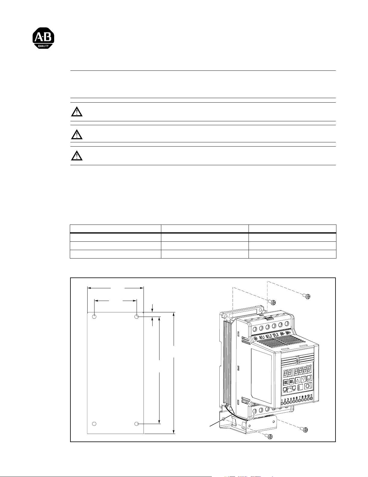
Choose an installation method:
• Install on 35mm DIN Rail.
• Install with screws. Recommended screw size is listed in the table below.
Description Metric English
Minimum Panel Thickness (14 GA) 1.9 mm 0.0747 in.
Mounting Base Screws M4 x 0.7 # 8-32
Mounting Torque 1.13 – 1.56 Nm 10 – 14 lb-in.
Mount bottom screws through mounting holes in fan bracket.
80
(3.15)
60
(2.36)
6.5
(.26)
172.2
(6.78)
151.6
(5.97)
Fan
Ground
Wire
Page 2
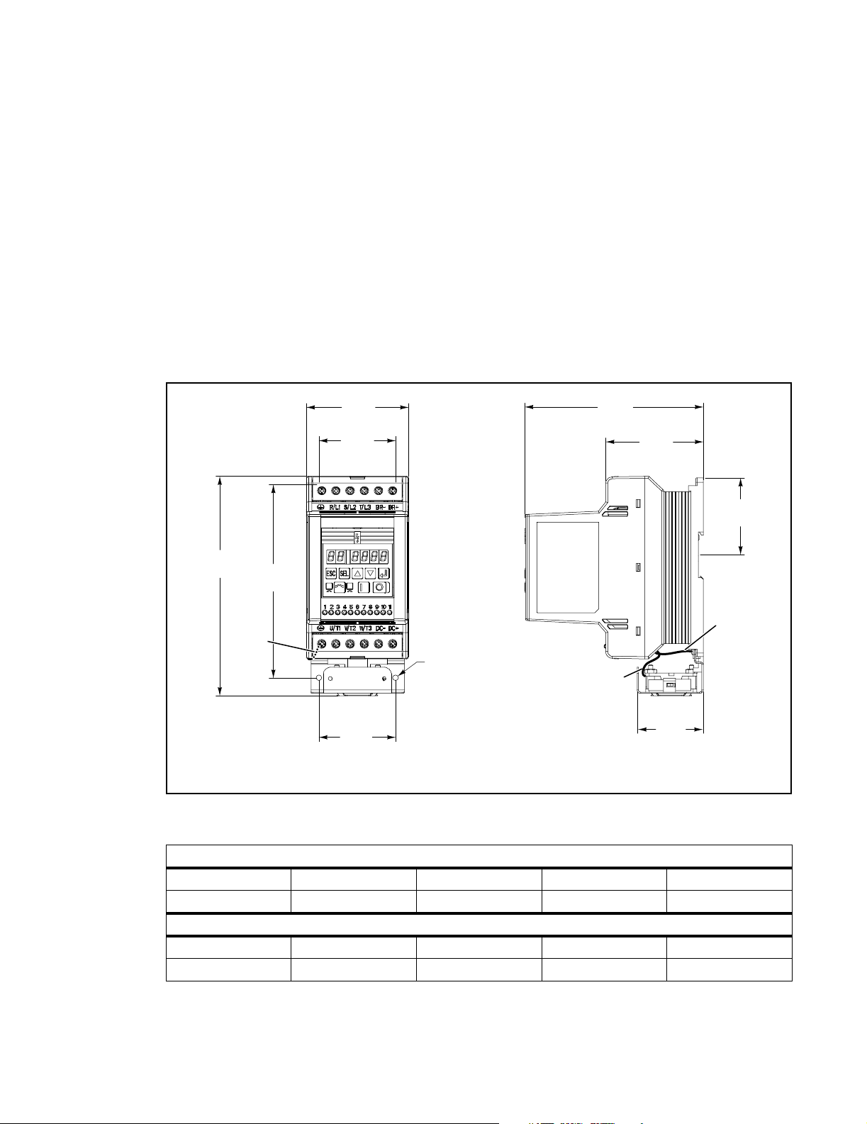
Maintain 12.5 mm (0.5 in.) clearance at the top, bottom, and front of drive. Provide a minimum
of 8.5 mm (0.33 in.) between units.
The 160-L requires grounding just as all 160s.
The fan bracket is wired to the load side ground terminal block. It is the User’s responsibility
to wire the system ground.
The ground terminal on the line side of the 160-L (top) can accept one or two 12 gage wires.
The ground terminal on the load side (bottom) of the 160-L can accept one 12 gage wire (due
to wire from fan bracket).
All dimensions are in millimeters and (inches), all weights are in kilograms and (pounds).
172.2
(6.78)
151.6*
Fan
Ground
Wire
(5.97)
80.0
(3.15)
59.9*
(2.36)
2 Mounting Holes
On Fan Bracket
59.9
(2.36)
* = Mounting Hole Dimensions
139.7
(5.50)
76.2
(3.00)
59.9
(2.36)
Fan
Ground
Wire
Fan
Wire
51.8
(2.04)
Drive Dimensions and Weights
200-240 VAC – 3-Phase
Drive H W D Weight
160-AA12L 172.2 (6.78) 80 (3.15) 140 (5.50) 0.84 (1.85)
380-460 VAC – 3-Phase
Drive H W D Weight
160-BA06L 172.2 (6.78) 80 (3.15) 140 (5.50) 0.84 (1.85)
Page 3

The following curves show the output ratings of a Low Profile Drive based on input voltage
and duty cycle. Duty cycle is calculated based on a 20 second on-time.
(For example: 25% duty cycle = 20 second on time, 60 second off time).
The heatsink of the 160-L is smaller than the heatsink of the standard Series C 160. The 160-L
can not dissipate heat as effectively as the standard Series C 160.
The purpose of these derating curves is to show how much current the 160-L may carry.
The maximum on time that can be used without 100% duty cycle derating is 20 seconds. To
illustrate how the charts function, consider the following examples:
1. 160-L is on for 1 second and off for 3 seconds, the duty cycle is 25%.
2. 160-L is on for 20 seconds and off for 20 seconds, the duty cycle is 50%.
3. 160-L is on for 40 seconds and off for 120 seconds, the duty cycle is 100%.
IMPORTANT: Since the on time in e xample 3 exceeds 20 seconds, 100% duty cycle derating
must be used regardless of the off time.
160-AA12L (230V)
Fan Cooled
12
10
8
6
Amps
4
2
0
0% 25% 50% 75% 100%
Duty Cycle (20 sec. On time)
Ambient Temperature 30C Ambient Temperature 40C Ambient Temperature 50C
Ambient = 30C
Ambient = 40C
Ambient = 50C
Page 4

160-BA06L (460V)
Fan Cooled
7
6
Ambient = 30C
5
Ambient = 40C
4
Amps
3
2
1
0
0% 25% 50% 75% 100%
Duty Cycle (20 sec. On time)
Ambient Temperature 30C Ambient Temperature 40C Ambient Temperature 50C
Ambient = 50C
Publication 0160-5.32 — May, 2000 P/N 195095 (01)
Copyright 2000 Rockwell International Corporation. All rights reserved. Printed in USA
 Loading...