

Page 1

DeviceNet™
Communication
Module
Catalog Number 160-DN2
Firmware 3.xxx
User Manual
Page 2

Important User Information
Solid state equipment has operational characteristics differing from those of
electromechanical equipment. “Safety Guidelines for the Application,
Installation and Maintenance of Solid State Controls” (Publication SGI-1.1
available from your local Rockwell Automation Sales Office or online at
http://www.ab.com/manuals/gi) describes some important differences
between solid state equipment and hard-wired electromechanical devices.
Because of this difference, and also because of the wide variety of uses for
solid state equipment, all persons responsible for applying this equipment
must satisfy themselves that each intended application of this equipment is
acceptable.
In no event will Rockwell Automation, Inc. be responsible or liable for
indirect or consequential damages resulting from the use or application of
this equipment.
The examples and diagrams in this manual are included solely for
illustrative purposes. Because of the many variables and requirements
associated with any particular installation, Rockwell Automation, Inc.
cannot assume responsibility or liability for actual use based on the
examples and diagrams.
No patent liability is assumed by Rockwell Automation, Inc. with respect to
use of information, circuits, equipment, or software described in this
manual.
Reproduction of the contents of this manual, in whole or in part, without
written permission of Rockwell Automation, Inc. is prohibited.
Throughout this manual we use notes to make you aware of safety
considerations.
ATTENTION: Identifies information about practices or
circumstances that can lead to personal injury or death, property
!
damage, or economic loss.
Attentions help you:
• identify a hazard
• avoid the hazard
• recognize the consequences
Important: Identifies information that is especially important for successful
application and understanding of the product.
Shock Hazard labels may be located on or inside the drive to
alert people that dangerous voltage may be present.
DeviceNet is a trademark of the Open DeviceNet Vendor Association.
SSC is a registered trademark of Rockwell Automation, Inc.
Allen-Bradley, ControlLogix, PLC-5, and SLC are trademarks of Rockwell Automation, Inc.
RSLinx, RSLogix, and RSNetWorx for DeviceNet are trademarks of Rockwell Software.
Page 3

Summary of Changes
The information below summarizes the changes made to this manual
since its last release (March, 1999):
Location Description of Changes
Chapter 3 Added three new sections — Surge-Suppression, Common Mode Noise,
and Output Disconnect — after the Low Voltage Directive 73/23/EEC
Compliance section.
Chapter 5 Added EDS file search screen and removed obsolete Table 6 (EDS files for
Bulletin 160 using a 160-DN2 version 3.000 or later).
Chapter 6 Replaced DeviceNet Manager software references and screens with those
of RSNetWorx for DeviceNet. Added I/O and explicit messaging information
and ladder logic examples for ControlLogix, PLC-5, and SLC controllers.
Chapter 7 In the “Understanding the FAULT LED” section, added Bulletin 160 Fault
Codes 11, 20, 36, and 46 to the table on pages 7-3
Appendix B In section “Class Code 0xB3 — 160 Parameter Table Object” in the
“Instance 1 Attributes” chart on pages B-18
Types for these Attribute IDs:
Attribute ID Parameter Name Data Type
9 Drive Status WORD (was USINT)
10 Drive Type USINT (was UINT)
12 Input Status WORD (was USINT)
15 Preset Status WORD (was USINT)
33 Maximum Freq UINT (was USINT)
35 Base Frequency UINT (was USINT)
39 Skip Frequency UINT (was USINT)
and 7-4.
and B-19, corrected the Data
In section “Class Code 0x04 — Assembly Objects,” subsection “Instance
Data Format: Output Assemblies” on page B-24
Instance 21 in bit 5 and bit 6 columns. Re-arranged numerical order of all
footnotes on this page.
In section “Class Code 0x04 — Assembly Objects,” subsection “Instance
Data Format: Output Assemblies” on page B-25
Instance 101 in bit 0, bit 1, and bit 2 columns. Re-arranged numerical order
of all footnotes on this page.
In section “Class Code 0x04 — Assembly Objects,” subsection
“Configuration Assembly Data Formats,” deleted unnecessary Instance 190
table (pages B-29 through B-34).
, added new footnotes for
, added a new footnote for
Publication 0160-5.18 - June 2003
Page 4

S-2 Summary of Changes
The March 1999 release of the Bulletin 160-DN2 DeviceNet
Communication Module User Manual covers the software
enhancements of Firmware Version 3.xxx and contains new and
updated information.
Bulletin 160-DN2 version 3.xxx
Software Enhancements
Compatibility with Bulletin 160 drives
(Series A, B, and C)
Features and enhancements in the 160-DN2 module that are different
than those in the 160-DN1 module include:
Bulletin 160 (Series A, B, and C) drives can be connected to a
DeviceNet network.
Ability to Create Electronic Data Sheets Configuration tools, such as DeviceNet Manager, can create an
Electronic Data Sheet (EDS file) for the 160 SSC drive and 160-DN2
module.
Added Parameter Object This object describes the parameters in the 160 SSC drive and
160-DN2 module.
Added Parameter Group Object This object describes the parameter groups associated with the
160 SSC drive and 160-DN2 module.
New and Revised Chapters to
this Manual
The bulletin 160-DN2 DeviceNet Communication Module User
Manual, Publication 0160-5.18, is a new manual. It is, however,
similar to the 160 DeviceNet Communication Module User Manual,
Publication 0160-5.5. The main differences can be found in the
following chapters:
Using This Manual Preface
Quick Start for Experienced Users Chapter 2
DeviceNet Parameter Descriptions Chapter 5
Using the 160-DN2 with DeviceNet Scanner Chapter 6
Troubleshooting Chapter 7
DeviceNet Information Appendix B
Summary of Enhancements to
User Manual
Publication 0160-5.18 - June 2003
Refer to the following references in this manual:
Reference Manuals Section P-2
Manual Organization P-3
DeviceNet Compatibility P-4
Replacing a 160-DN1 with a 160-DN2 P-4
Required Tools and Equipment 3-1
DeviceNet Parameter Descriptions Chapter 5
Creating EDS Files replaces Installing EDS Files 6-3
Troubleshooting Updated Chapter 7
Parameter Object B-9
Parameter Group Object B-11
Acknowledge Handler Object B-17
Page 5

Table of Contents
Preface
Using This Manual Manual Objectives. . . . . . . . . . . . . . . . . . . . . . . . . . . . . . . . . . . . . . . . . . . . . . . . P-1
Who Should Use This Manual?. . . . . . . . . . . . . . . . . . . . . . . . . . . . . . . . . . . . . . P-1
Product References . . . . . . . . . . . . . . . . . . . . . . . . . . . . . . . . . . . . . . . . . . . . . . P-1
Conventions . . . . . . . . . . . . . . . . . . . . . . . . . . . . . . . . . . . . . . . . . . . . . . . . . . . . P-1
Firmware Version . . . . . . . . . . . . . . . . . . . . . . . . . . . . . . . . . . . . . . . . . . . . . . . . P-1
Related Documentation. . . . . . . . . . . . . . . . . . . . . . . . . . . . . . . . . . . . . . . . . . . . P-2
Manual Organization. . . . . . . . . . . . . . . . . . . . . . . . . . . . . . . . . . . . . . . . . . . . . . P-2
Safety Precautions . . . . . . . . . . . . . . . . . . . . . . . . . . . . . . . . . . . . . . . . . . . . . . . P-3
DeviceNet Compatibility . . . . . . . . . . . . . . . . . . . . . . . . . . . . . . . . . . . . . . . . . . . P-4
Replacing a 160-DN1 with a 160-DN2 . . . . . . . . . . . . . . . . . . . . . . . . . . . . . . . . P-4
Rockwell Automation Support. . . . . . . . . . . . . . . . . . . . . . . . . . . . . . . . . . . . . . . P-4
Chapter 1
Product Overview Module Description . . . . . . . . . . . . . . . . . . . . . . . . . . . . . . . . . . . . . . . . . . . . . . . 1-1
LEDs and DeviceNet Connection . . . . . . . . . . . . . . . . . . . . . . . . . . . . . . . . . . . . 1-1
DIP Switches. . . . . . . . . . . . . . . . . . . . . . . . . . . . . . . . . . . . . . . . . . . . . . . . . . . . 1-2
Chapter 2
Quick Start for
Experienced Users
Introduction . . . . . . . . . . . . . . . . . . . . . . . . . . . . . . . . . . . . . . . . . . . . . . . . . . . . . 2-1
Required Tools and Equipment. . . . . . . . . . . . . . . . . . . . . . . . . . . . . . . . . . . . . . 2-1
Procedures . . . . . . . . . . . . . . . . . . . . . . . . . . . . . . . . . . . . . . . . . . . . . . . . . . . . . 2-2
Chapter 3
Installation and Wiring Required Tools and Equipment . . . . . . . . . . . . . . . . . . . . . . . . . . . . . . . . . . . . . 3-1
EMC Directive 89/336/EEC Compliance. . . . . . . . . . . . . . . . . . . . . . . . . . . . . . . 3-2
Low Voltage Directive 73/23/EEC Compliance . . . . . . . . . . . . . . . . . . . . . . . . . . 3-2
Surge Suppression . . . . . . . . . . . . . . . . . . . . . . . . . . . . . . . . . . . . . . . . . . . . . . . 3-2
Common Mode Noise . . . . . . . . . . . . . . . . . . . . . . . . . . . . . . . . . . . . . . . . . . . . 3-4
Drive Output Disconnect . . . . . . . . . . . . . . . . . . . . . . . . . . . . . . . . . . . . . . . . . . 3-4
Removing Program Keypad Module or Ready/Fault Panel . . . . . . . . . . . . . . . . 3-5
Understanding Module Configuration Switches . . . . . . . . . . . . . . . . . . . . . . . . . 3-5
Setting the DeviceNet Node Address . . . . . . . . . . . . . . . . . . . . . . . . . . . . . . . . . 3-6
Setting the Baud Rate. . . . . . . . . . . . . . . . . . . . . . . . . . . . . . . . . . . . . . . . . . . . . 3-7
Cable Lengths and Baud Rates . . . . . . . . . . . . . . . . . . . . . . . . . . . . . . . . . . . 3-7
Installing the Communication Module . . . . . . . . . . . . . . . . . . . . . . . . . . . . . . . . . 3-8
Wiring the DeviceNet Connector. . . . . . . . . . . . . . . . . . . . . . . . . . . . . . . . . . . . . 3-9
Connecting the DeviceNet Drop Line to the Module . . . . . . . . . . . . . . . . . . . . . 3-10
Removing Communication Module From a Drive . . . . . . . . . . . . . . . . . . . . . . 3-10
Publication 0160-5.18 - June 2003
Page 6

ii Table of Contents
Chapter 4
Modes of Operation Powering Up the Drive . . . . . . . . . . . . . . . . . . . . . . . . . . . . . . . . . . . . . . . . . . . . 4-1
Modes of Operation. . . . . . . . . . . . . . . . . . . . . . . . . . . . . . . . . . . . . . . . . . . . . . . 4-1
Power-up Reset Mode. . . . . . . . . . . . . . . . . . . . . . . . . . . . . . . . . . . . . . . . . . . 4-1
Run Mode . . . . . . . . . . . . . . . . . . . . . . . . . . . . . . . . . . . . . . . . . . . . . . . . . . . . 4-2
Error Mode . . . . . . . . . . . . . . . . . . . . . . . . . . . . . . . . . . . . . . . . . . . . . . . . . . . 4-2
Chapter 5
DeviceNet Parameter
Descriptions
DeviceNet Parameters . . . . . . . . . . . . . . . . . . . . . . . . . . . . . . . . . . . . . . . . . . . . 5-1
Electronic Data Sheet (EDS) Files . . . . . . . . . . . . . . . . . . . . . . . . . . . . . . . . . . . 5-1
Parameters and EDS File . . . . . . . . . . . . . . . . . . . . . . . . . . . . . . . . . . . . . . . . . . 5-1
Bulletin 160 SSC Interface . . . . . . . . . . . . . . . . . . . . . . . . . . . . . . . . . . . . . . . . . 5-2
Locating EDS Files on the Internet . . . . . . . . . . . . . . . . . . . . . . . . . . . . . . . . . . . 5-2
Bulletin 160 SSC Interface Parameters . . . . . . . . . . . . . . . . . . . . . . . . . . . . . . . 5-3
DeviceNet Parameters . . . . . . . . . . . . . . . . . . . . . . . . . . . . . . . . . . . . . . . . . . . . 5-3
Drive Display Parameters (Read Only). . . . . . . . . . . . . . . . . . . . . . . . . . . . . . . . 5-6
Drive Program Parameters . . . . . . . . . . . . . . . . . . . . . . . . . . . . . . . . . . . . . . . . . 5-8
Using 160-DN2 with
DeviceNet Scanner
Chapter 6
Needed Tools . . . . . . . . . . . . . . . . . . . . . . . . . . . . . . . . . . . . . . . . . . . . . . . . . . . 6-2
Setting Device MAC ID’s. . . . . . . . . . . . . . . . . . . . . . . . . . . . . . . . . . . . . . . . . . . 6-2
Using RSNetWorx for DeviceNet . . . . . . . . . . . . . . . . . . . . . . . . . . . . . . . . . . . . 6-2
Going Online . . . . . . . . . . . . . . . . . . . . . . . . . . . . . . . . . . . . . . . . . . . . . . . . . . 6-2
Creating an EDS File . . . . . . . . . . . . . . . . . . . . . . . . . . . . . . . . . . . . . . . . . . . 6-3
Accessing and Editing Parameters . . . . . . . . . . . . . . . . . . . . . . . . . . . . . . . . . 6-4
Selecting Input and Output Assemblies for I/O Messaging . . . . . . . . . . . . . . . . 6-5
Changing the Output Assembly . . . . . . . . . . . . . . . . . . . . . . . . . . . . . . . . . . . 6-6
Changing the Input Assembly . . . . . . . . . . . . . . . . . . . . . . . . . . . . . . . . . . . . . 6-6
Enabling Network Control . . . . . . . . . . . . . . . . . . . . . . . . . . . . . . . . . . . . . . . . . . 6-7
Configuring Drive Input Mode . . . . . . . . . . . . . . . . . . . . . . . . . . . . . . . . . . . . 6-7
Modifying Drive Reset Functions . . . . . . . . . . . . . . . . . . . . . . . . . . . . . . . . . . 6-8
Configuring the 160 to Accept Speed Commands from the Network . . . . . . . . . 6-9
Configuring the Scanner . . . . . . . . . . . . . . . . . . . . . . . . . . . . . . . . . . . . . . . . . . 6-10
Example Network . . . . . . . . . . . . . . . . . . . . . . . . . . . . . . . . . . . . . . . . . . . . . 6-10
Setting Up the Scan List . . . . . . . . . . . . . . . . . . . . . . . . . . . . . . . . . . . . . . . . 6-11
Mapping the Drive Data in the Scanner . . . . . . . . . . . . . . . . . . . . . . . . . . . . 6-13
Saving the Configuration. . . . . . . . . . . . . . . . . . . . . . . . . . . . . . . . . . . . . . . . 6-16
Using I/O Messaging. . . . . . . . . . . . . . . . . . . . . . . . . . . . . . . . . . . . . . . . . . . . . 6-16
Example Ladder Logic Programs . . . . . . . . . . . . . . . . . . . . . . . . . . . . . . . . . 6-16
ControlLogix Example . . . . . . . . . . . . . . . . . . . . . . . . . . . . . . . . . . . . . . . . . 6-17
PLC-5 Example . . . . . . . . . . . . . . . . . . . . . . . . . . . . . . . . . . . . . . . . . . . . . . 6-19
SLC Example . . . . . . . . . . . . . . . . . . . . . . . . . . . . . . . . . . . . . . . . . . . . . . . . 6-21
Using Explicit Messaging . . . . . . . . . . . . . . . . . . . . . . . . . . . . . . . . . . . . . . . . . 6-23
About Explicit Messaging . . . . . . . . . . . . . . . . . . . . . . . . . . . . . . . . . . . . . . . 6-23
Formatting Explicit Messages . . . . . . . . . . . . . . . . . . . . . . . . . . . . . . . . . . . . 6-23
Executing Explicit Messages. . . . . . . . . . . . . . . . . . . . . . . . . . . . . . . . . . . . . 6-29
Publication 0160-5.18 - June 2003
Page 7

Table of Contents iii
Chapter 7
Troubleshooting Understanding the COMM LED . . . . . . . . . . . . . . . . . . . . . . . . . . . . . . . . . . . . . 7-2
Understanding the FAULT LED . . . . . . . . . . . . . . . . . . . . . . . . . . . . . . . . . . . . . 7-3
Appendix A
Specifications Electrical . . . . . . . . . . . . . . . . . . . . . . . . . . . . . . . . . . . . . . . . . . . . . . . . . . . . . A-1
Environmental . . . . . . . . . . . . . . . . . . . . . . . . . . . . . . . . . . . . . . . . . . . . . . . . A-1
Communications . . . . . . . . . . . . . . . . . . . . . . . . . . . . . . . . . . . . . . . . . . . . . . A-1
Mechanical . . . . . . . . . . . . . . . . . . . . . . . . . . . . . . . . . . . . . . . . . . . . . . . . . . . A-1
Appendix B
DeviceNet Information DeviceNet Message Types . . . . . . . . . . . . . . . . . . . . . . . . . . . . . . . . . . . . . . . . . B-1
Object Classes . . . . . . . . . . . . . . . . . . . . . . . . . . . . . . . . . . . . . . . . . . . . . . . . . . B-2
Supported Data Types . . . . . . . . . . . . . . . . . . . . . . . . . . . . . . . . . . . . . . . . . . . . B-2
Class Code 0x01 — Identity Object . . . . . . . . . . . . . . . . . . . . . . . . . . . . . . . . B-3
Class Code 0x03 — DeviceNet Object . . . . . . . . . . . . . . . . . . . . . . . . . . . . . . B-5
Class Code 0x05 — Connection Object . . . . . . . . . . . . . . . . . . . . . . . . . . . . . B-6
Class Code 0x0F — Parameter Object. . . . . . . . . . . . . . . . . . . . . . . . . . . . . . B-9
Class Code 0x10 — Parameter Group Object . . . . . . . . . . . . . . . . . . . . . . . B-11
Class Code 0x28 — Motor Data Object . . . . . . . . . . . . . . . . . . . . . . . . . . . . B-12
Class Code 0x29 — Control Supervisor Object . . . . . . . . . . . . . . . . . . . . . . B-13
State Transition Diagram. . . . . . . . . . . . . . . . . . . . . . . . . . . . . . . . . . . . . . B-14
Run/Stop Event Matrix . . . . . . . . . . . . . . . . . . . . . . . . . . . . . . . . . . . . . . . B-15
Class Code 0x2A — AC Drive Object . . . . . . . . . . . . . . . . . . . . . . . . . . . . . . B-16
Class Code 0x2B — Acknowledge Handler Object . . . . . . . . . . . . . . . . . . . B-17
Class Code 0xB3 — 160 Parameter Table Object . . . . . . . . . . . . . . . . . . . . B-18
Class Code 0xB4 — DN Interface Object . . . . . . . . . . . . . . . . . . . . . . . . . . . B-22
Class Code 0x04 — Assembly Objects . . . . . . . . . . . . . . . . . . . . . . . . . . . . B-23
Instance Data Format: Output Assemblies . . . . . . . . . . . . . . . . . . . . . . . . B-24
Instance Data Format: Input Assemblies . . . . . . . . . . . . . . . . . . . . . . . . . B-26
Configuration Assembly Data Formats . . . . . . . . . . . . . . . . . . . . . . . . . . . B-29
Index
Publication 0160-5.18 - June 2003
Page 8

iv Table of Contents
Publication 0160-5.18 - June 2003
Page 9

Preface
Using This Manual
Manual Objectives The purpose of this manual is to provide you with the necessary
information to apply the Bulletin 160 SSC DeviceNet
Communication Module. This manual describes methods to install,
configure, and troubleshoot the Bulletin 160 SSC DeviceNet
Communication Module.
For information on specific features of the Bulletin 160 SSC drive,
refer to the Bulletin 160 SSC User Manual.
Important: Read this manual in its entirety before installing,
operating, servicing, or initializing the Bulletin 160 DeviceNet
Communication Module.
Who Should Use This Manual? This manual is intended for qualified personnel. To make efficient use
of the Communication Module, you must be able to program and
operate serial communications devices, as well as have an
understanding of the parameter settings and functions of the Bulletin
160 SSC drive.
You should understand DeviceNet network operations, including how
slave devices operate on the network and communicate with a
DeviceNet master.
Product References In this manual we refer to the:
• Bulletin 160-DN2 DeviceNet Communication Module as
Communication Module and Module.
• Bulletin 160 SSC Variable Frequency AC Drive as the Drive.
Conventions Parameter names are shown in the format PXX - [*] where P denotes
parameter, XX represents the parameter number, and * represents the
parameter name. For example, P01 - [Output Frequency].
Firmware Version The firmware release is displayed as FRN X.xxx, where:
FRN = Firmware Release Number
X = Firmware (whole) Number
(.) = Decimal point separator
xxx = Place holders representing minor updates
Places to the right of the decimal do not affect content of this manual.
Publication 0160-5.18 - June 2003
Page 10

P-2 Using This Manual
Related Documentation
For: Refer to: Publication
Bulletin 160 SSC
Drive
RSNetWorx for
DeviceNet Software
ControlLogix ControlLogix User Manual 1756-6.5.13
SLC 500 and
1747-SDN
PLC5
and 1771-SDN
DeviceNet Cables
and Components
DeviceNet Network
Installation
User Manual Series A
User Manual Series B
User Manual Series C
RSNetWorx for DeviceNet Getting Results Guide
Online help (installed with the software)
DeviceNet Scanner Module Installation Instructions
DeviceNet Scanner Module Configuration Manual
DeviceNet Scanner Module Installation Instructions
DeviceNet Scanner Module Configuration Manual
DeviceNet Product Overview DN-2.5
DeviceNet Cable System Planning and Installation
Manual
0160-5.0
0160-5.9
0160-5.15
9398-DNETGR
1747-5.8
1747-6.5.2
1771-5.14
1771-6.5.118
DN-6.7.2
Important: Read the DeviceNet Cable System Planning and
Installation Manual, Publication DN-6.7.2, in its entirety before
planning and installing a DeviceNet system. If the network is not
installed according to this document, unexpected operation and
intermittent failures can occur.
Documentation can be obtained online at http://www.ab.com/manuals.
Manual Organization This 160-DN2 Module user manual contains the following sections:
Chapter Title Contents
Preface Using This Manual Manual objectives, audience, vocabulary, manual
conventions and organization, safety precautions,
and DeviceNet compatibility.
1 Product Overview Module description, LEDs, DIP switches, and
DeviceNet compatibility.
2 Quick Start for
Experienced Users
3 Installation and Wiring Installation, switch configuration, cabling, and
4 Modes of Operation Power-up and modes of operation.
5 DeviceNet Parameter
Descriptions
6 Using 160-DN2 with
DeviceNet Scanner
7 Troubleshooting LED indications and fault descriptions.
Appendix A Specifications Environmental, electrical, and communication
Appendix B DeviceNet Information DeviceNet message types and object classes.
Communication Module features, configuration,
and diagnostics.
removal.
EDS file parameters, Bulletin 160 SSC interface,
product codes.
Mac IDs, RSNetWorx for DeviceNet, configuration,
input/output assemblies, network control, scan list,
I/O messaging, ladder program examples, explicit
messaging.
specifications.
Publication 0160-5.18 - June 2003
Page 11
Using This Manual P-3
Safety Precautions Please read the following safety precautions carefully:
ATTENTION: Risk of injury or death exists. The
drive contains high voltage capacitors which take time
!
!
to discharge after removal of mains supply. Before
installing or removing the DeviceNet Communication
Module, make sure to isolate the mains supply from line
inputs [L1, L2, L3 (R, S, T)]. Wait three minutes for
capacitors to discharge to safe voltage levels. Failure to
do so may result in injury or death.
ATTENTION: Risk of injury or equipment damage
exists. Only personnel familiar with DeviceNet devices,
Bulletin 160 SSC drives, and associated machinery
should plan or implement the installation, start-up,
configuration, and subsequent maintenance of the
Communication Module. Failure to comply may result
in injury and/or equipment damage.
ATTENTION: Risk of equipment damage exists. This
module contains ESD (Electrostatic Discharge)
!
!
!
sensitive parts that can be damaged if you do not follow
ESD control procedures. Static control precautions are
required when handling this Communication Module.
If you are unfamiliar with static control procedures,
refer to Guarding Against Electrostatic Damage,
Publication 8000-4.5.2.
ATTENTION: Risk of injury or equipment damage
exists. When a system is configured for the first time,
there may be unintended or incorrect machine motion.
Disconnect the motor from the machine or process
during initial system testing.
ATTENTION: Hazard of equipment damage exists. If
explicit messages are programmed to frequently change
parameter data in the drive, the EEPROM will quickly
exceed its life cycle and cause the drive to malfunction.
Do not create a program that frequently uses explicit
messages to change a parameter in the drive.
Publication 0160-5.18 - June 2003
Page 12

P-4 Using This Manual
DeviceNet Compatibility The 160-DN2 Communication Module is intended for use only with
Bulletin 160 SSC Series A, Bulletin 160 SSC Series B, and Bulletin
160 SSC Series C (FRN 7.03 and later) devices. Bulletin 160 SSC
(Series C) devices must use a 160-DN2 Communication Module to
connect to a DeviceNet network. Bulletin 160 SSC (Series A and B)
devices can use either a 160-DN2 or 160-DN1 Communication
Module to connect to a DeviceNet network.
When properly connected, the Communication Module
communicates via the DeviceNet Protocol. The Communication
Module/Bulletin 160 SSC combination comprise a Group 2 Slave
Only device. This device supports DeviceNet slave Polled, Change of
State/Cyclic messaging, and DeviceNet slave Explicit messaging. It
does not support the Explicit Unconnected Message Manager
(UCMM).
Replacing a 160-DN1 with a
160-DN2
You can replace a 160-DN1 Communication Module with a 160-DN2
Communication Module on any 160 SSC (Series A and Series B)
drive. To do so, you will need to create an EDS file for the new 160DN2 Communication Module and map the module to the network.
Chapter 6
, Using 160-DN2 with DeviceNet Scanner, provides
detailed instructions on how to perform these tasks.
Rockwell Automation Support Rockwell Automation, Inc. offers support services worldwide, with
over 75 sales/support offices, over 500 authorized distributors, and
over 250 authorized systems integrators located through the United
States alone. In addition, Rockwell Automation, Inc. representatives
are in every major country in the world.
Local Product Support — Contact your local Rockwell
Automation, Inc. representative for sales and order support, product
technical training, warranty support, and support service agreements.
Technical Product Assistance — If you need to contact Rockwell
Automation, Inc. for technical assistance, please review the
information in Chapter 7
problems, then call your local Rockwell Automation, Inc.
representative.
, Troubleshooting first. If you still have
Publication 0160-5.18 - June 2003
U.S. Allen-Bradley Drives Technical Support:
E-mail: support@drives.ra.rockwell.com
Tel: (1) 262.512.8176
Fax (1) 262.512.2222
Online: www.ab.com/support/abdrives
UK Customer Support Center:
E-mail: esupport2@ra.rockwell.com
Tel: +44 (0) 870 2411802
Fax: +44 (0) 1908 838804
Germany Customer Service Center:
E-mail: ragermany-csc@ra.rockwell.com
Tel: +49 (0) 2104 960-630
Fax: +49 (0) 2104 960-501
Page 13
Chapter 1
Product Overview
This chapter contains the following information:
• physical layout of the module
• location of configuration switches
• DeviceNet overview and components
Module Description The Bulletin 160 SSC DeviceNet Communication Module is an
optional interface device designed to provide a direct, digital link
between DeviceNet devices and the Bulletin 160 SSC drive. The
module connects to the Bulletin 160 SSC through the expansion/
keypad port on the front of the drive.
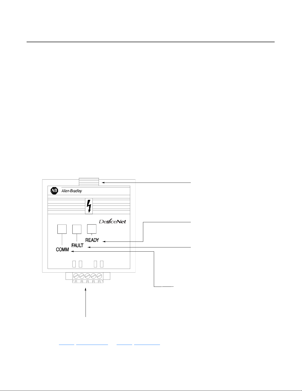
LEDs and DeviceNet Connection Figure 1.1
Module Front View
TM
CONFORMANCE TESTED
DeviceNet Terminal Block Plug - The Communication Module
receives power and communications through this connector.
Module Installation Latch
Ready LED - GREEN when drive is powered up ➀
Fault LED - RED when drive is faulted
OFF when drive not faulted ➀
COMM - This bi-colored LED (red/green) provides status
information on DeviceNet communications ➀
➀ See Chapter 4, Modes of Operation, and Chapter 7, Troubleshooting, for detailed operation.
Publication 0160-5.18 - June 2003
Page 14
1-2 Product Overview
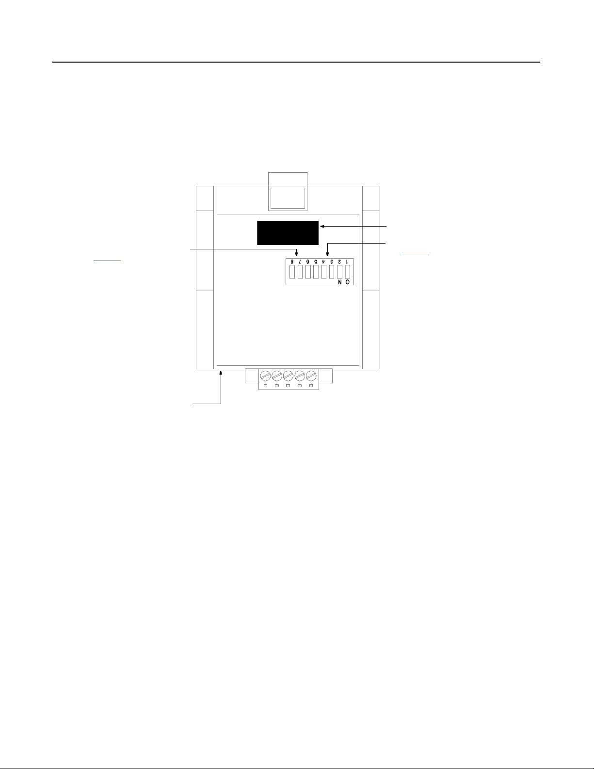
DIP Switches Figure 1.2
Module Rear View
The Communication Module has one eight position DIP switch for setting the
DeviceNet Node Address and Baud Rate. DIP switches are located on the
rear of the module and are only accessible when the module is removed
from the Bulletin 160 SSC drive.
Expansion/Keypad Port Connector
SW.7 - SW.8 = Baud Rate Selection
(see page 3-7
Label with DeviceNet Serial Number
)
SW.1 - SW.6 = Node Address Selection
(see page 3-6
)
Publication 0160-5.18 - June 2003
Page 15

Chapter 2
Quick Start for Experienced Users
Introduction This chapter can help you start using the Bulletin 160 DeviceNet
Communication module. If you have previously installed or
configured a DeviceNet network and are familiar with Rockwell
Automation DeviceNet modules and drives, this information can help
reduce installation and startup time. If you are uncertain, use the full
installation/configuring information beginning in Chapter 3
We base the procedures listed in this chapter on the assumption that
you understand DeviceNet concepts and know how to program the
Bulletin 160 SSC drive. You should also be able to understand
electronic process control and interpret the ladder logic instructions
required to generate the electronic signals that control your
application.
Because it is a start-up guide for experienced users, this chapter does
not contain detailed explanations about the procedures listed. It does,
however, reference other chapters in this book where you can get
more information.
.
If you have any questions or are unfamiliar with the terms used or
concepts presented in the procedural steps, always read the
referenced chapters and other recommended documentation before
trying to apply the information.
The information contained in this chapter includes:
• What tools and equipment you will need.
• When to address, configure, and program the module.
• How to install and wire the Communication Module.
• System power-up procedures.
Required Tools and Equipment Have the following tools and equipment ready:
• small blade screwdriver
• DeviceNet configuration software or hardware device
Publication 0160-5.18 - June 2003
Page 16

2-2 Quick Start for Experienced Users
Procedures
Step Refer to . . .
1 Review Attention statements in the Preface. Preface
2 Check the contents of the shipping box.
Unpack the shipping box, making sure that it contains:
• Bulletin 160 DeviceNet module (Catalog Number 160-DN2)
• 10-pin linear plug with probe holes and jack screws
• DeviceNet Communication Module 160-DN2 User Manual
If the contents are incomplete, call your local Allen-Bradley
representative for assistance.
3 Ensure that the drive is correctly installed and wired. (The
Stop Input, TB3-7 and TB3-8, must be jumpered together
to start the drive.)
4 Ensure that the DeviceNet master and network are
installed and functioning by DeviceNet standards.
5 Remove the Program Keypad Module or
Ready/Fault Indicating Panel from the drive.
6 Set the DeviceNet Module’s node address and baud rate.
Set the DIP Switches at the back of the module. Switches 1
through 6 set the node address; switches 7 and 8 set baud
rate.
7 Install the DeviceNet module on the drive. Chapter 3,
8 Wire the DeviceNet connector and plug it into the drive. Chapter 3,
9 Power up the drive and the network.
Important: When power-up occurs, the COMM
(communication status) LED flashes green for 1/4 second, red
for 1/4 second, and then goes blank while the Communication
Module finishes its initialization. If the COMM LED goes red,
there is a problem.
10 Select the appropriate Electronic Data Sheet (EDS) file.
Select the EDS file with the DeviceNet software or hardware
configurator that you are using to configure the Communication
Module (see Chapter 5
11 Configure the Bulletin 160 SSC drive for DeviceNet so that
the drive can accept speed reference and control logic via
the network.
Use configuration software such as RSNetWorx for DeviceNet
or hardware such as DeviceView Hand Held DeviceNet
Configurator.
12 Configure the DeviceNet Scanner to recognize the Bulletin
160 SSC drive.
Use RSNetWorx for DeviceNet to configure the DeviceNet
Scanner’s “Scan List” to recognize the Bulletin 160 SSC drive.
for EDS file descriptions).
—
Publication 160-SSC
User Manual
DeviceNet Cable
System Planning and
Installation Manual
(Publication DN-6.7.2)
Chapter 3
Installation and Wiring
Chapter 3,
Installation and Wiring
Installation and Wiring
Installation and Wiring
Chapter 3
Installation and Wiring,
Chapter 4
Modes of Operation,
and
Chapter 7
Troubleshooting
Chapter 6
Using 160-DN2 with
DeviceNet Scanner,
and DeviceNet
Software or Hardware
Configurator Manual
Chapter 6
Using 160-DN2 with
DeviceNet Scanner
Chapter 6,
Using 160-DN2 with
DeviceNet Scanner
,
,
,
,
,
,
Publication 0160-5.18 - June 2003
Page 17
Chapter 3
Installation and Wiring
This chapter contains information necessary to:
• Meet requirements for CE compliance (EMC / Low Voltage directives).
• Suppress transient EMI from “hard contact” load switching.
• Reduce high frequency common mode noise current.
• Properly connect/disconnect power to the motor.
• Remove a preinstalled Program Keypad Module or Ready/Fault
Indicating Panel.
• Configure and install the Communication Module.
• Wire the DeviceNet communication cables.
• Remove an installed Communication Module from the drive.
Read this chapter completely before you attempt to install or
configure the Communication Module. Before you apply power,
review the Safety Precautions
all connections are secure and all selections are correct.
on Preface page P-3, making sure that
ATTENTION: When you make changes to the
switch settings, use a blunt pointed instrument. Do not
!
!
use a pencil or pen because damage may occur.
ATTENTION: Unpredictable operation may occur if
you fail to check connections and DIP switch settings
for compatibility with your application. Unpredictable
operation may result in personal injury, death, and
equipment damage.
Required Tools and Equipment Before installing and configuring the 160-DN2 Communication
Module, make sure that the contents of the shipping box include:
• Bulletin 160-DN2 module (Catalog Number 160-DN2)
• 10 pin linear Plug (Part Number 1787-PLUG10R)
• this manual
In addition, you will need to supply:
• a small blade screwdriver
• DeviceNet configuration software or hardware device
• DeviceNet thick cable or thin cable. For details and part numbers,
refer to the DeviceNet Product Overview, Publication DN-2.5.
Publication 0160-5.18 - June 2003
Page 18

3-2 Installation and Wiring
EMC Directive 89/336/EEC
Compliance
Low Voltage Directive 73/23/EEC
Compliance
The 160-DN2 Communication Module complies with
Electromagnetic Compatibility (EMC) Directive 89/336/EEC when
conforming to these installation requirements:
• Applying the essential requirements for a conforming EMC
installation for the Bulletin 160 SSC drive. Refer to the Bulletin
160 SSC User Manual.
• Connecting the DeviceNet cable shield to the SSC drive’s
protective earth terminal, PE, with a low impedance connection.
• Installing a clamp-on ferrite cable clamp (see Figure 3.9
DeviceNet communication cable within 10 cm (4 in.) of the SSC
drive. When multiple SSC drives are contained in one control
cabinet, it is sufficient to install one clamp-on ferrite cable clamp
where the DeviceNet communication cable enters the control
cabinet.
The 160-DN2 Communication Module complies with Low Voltage
Directive 73/23/EEC when conforming to these installation
requirements:
• Applying the essential requirements for a conforming Low Voltage
Directive installation for the Bulletin 160 SSC drive. Refer to the
Bulletin 160 SSC User Manual.
) on the
• Observing the Safety Precautions
Attention statements throughout this manual when installing the
module.
on Preface page P-3, and other
Surge Suppression Transient EMI can be generated whenever inductive loads such as
relays, solenoids, electro-mechanical brakes, motor starters, or motors
are operated by “hard contacts.” The wiring guidelines contained
herein are based on the assumption that you safeguard your system
against the effects of transient EMI by using surge suppressors to
suppress transient EMI at its source. Inductive loads switched by only
solid-state output devices do not require surge suppression. However,
inductive loads that are in series or parallel with hard contacts require
surge suppression to protect control circuits as well as to suppress
transient EMI.
Even if regularly cycled inductive loads have no interaction with
the control system, these loads need suppression if their
conductors are:
• Connected to the same separately derived system as that of the
control system.
• Routed in proximity with conductors of the control system (per
routing guidelines).
Publication 0160-5.18 - June 2003
The application (voltage and load of the inductive circuit) dictates the
specific suppressor needed at the source of the inductive load. Testing
has determined that the best overall RC surge suppressor combination
Page 19
Installation and Wiring 3-3
is 220 ohms and 0.50 microfarads. Select the voltage rating for the
normal AC voltages. A typical surge suppressor that can be used for
most transient EMI problems is Electrocube part number RG1676-16
(rated 480V ac).
Surge suppressors are usually most effective when connected at the
inductive loads. However, you can also connect surge suppressors at
the switching devices, but they may be less effective because the
wires connecting the switching devices to the inductive loads act as
antennas that radiate EMI. You can evaluate the effectiveness of a
particular suppressor by using an oscilloscope to observe the voltage
waveform on the line.
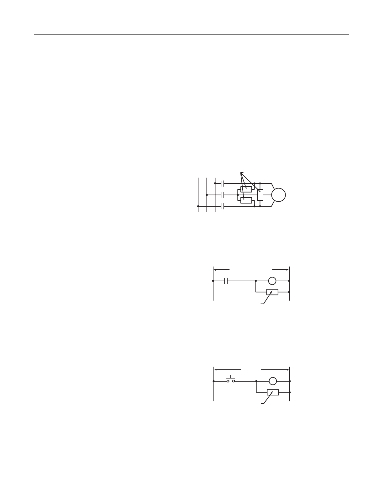
Figure 3.1
Surge Suppressor Connection for 3-Phase Apparatus
230/460VAC
For 3-phase apparatus, a suppressor is needed across each phase
Surge Suppressor
3-Phase
Motor
Figure 3.2
Surge Suppressor Connection for Large Apparatus
115/230/460VAC
Surge Suppressor
For large apparatus (electro-mechanical brakes, contacts up to size 5)
Figure 3.3
Surge Suppressor Connection for Small Apparatus
115VAC
Surge Suppressor
For small apparatus (relays, solenoids, and motor starters up to size 1)
Publication 0160-5.18 - June 2003
Page 20

3-4 Installation and Wiring
Common Mode Noise To greatly reduce high frequency common mode noise current
coupled to ground in high capacitance connections, connect a
common mode choke at the drive end of the motor cable. The
common mode choke reduces the rise time of the high frequency
noise by a factor of 10-20, and the amplitude by a factor of 5. For
multiple 460 volt drive installations with sensitive equipment (e.g.
PLC’s, temperature sensors, sonar detectors, strain gauges, etc.)
sharing a common ground separated by more than 30 feet, you must
install common mode chokes at the outputs of each drive.
In addition to greatly reducing high frequency common mode noise
induced by the drive, a common mode choke also effectively reduces
high frequency common mode noise that is induced by regularly
cycled inductive loads. In installations where inductively-coupled
common mode noise causes system problems, connect a common
mode choke at the source of the inductively-switched load.
For drives on a DeviceNet network, we highly recommend connecting
a common mode choke at the drive end of the motor cable.
Drive Output Disconnect The drive is intended to be commanded by control signals that will
start and stop the motor. Do not use a device that routinely connects
or disconnects output power to the motor with the drive outputting
power (for the purpose of starting and stopping the motor, or for
machine positioning). Connecting or disconnecting power to the
motor with the drive outputting power can produce transient EMI
which can cause network problems to occur.
For emergency stop conditions, make sure that terminal 7 and 8 on
TB2 is broken (opened) using an auxiliary contact of a motor output
contactor. Also, remember to set the Stop Select parameter to “Coast
to Stop.”
Publication 0160-5.18 - June 2003
Page 21
Installation and Wiring 3-5
P
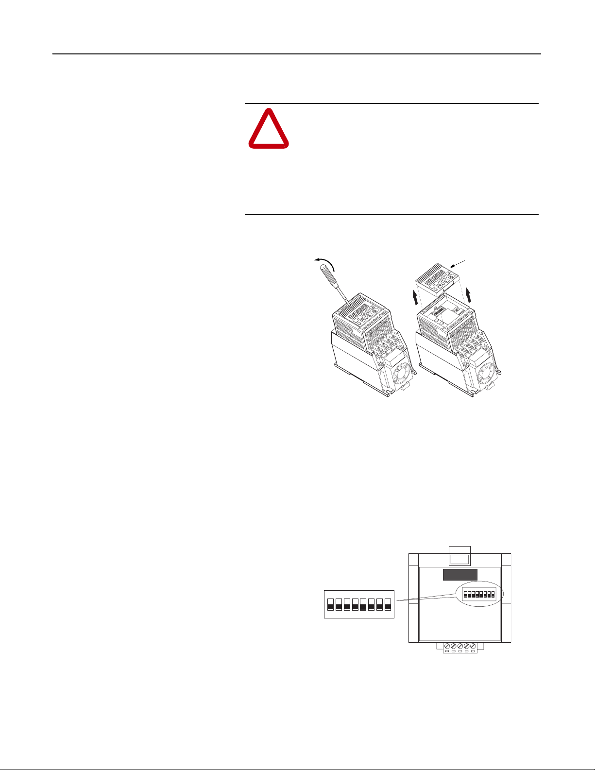
Removing Program Keypad Module
or Ready/Fault Panel
Insert a small screw driver into the slot, pry
back, and pivot module out. Avoid bending
or twisting the contact pins located
underneath the center portion of the
module.
Before installing the Communication Module, it may be necessary to
remove a previously installed module such as a Program Keypad
Module or Ready/Fault Indicating panel.
ATTENTION: Risk of injury or death exists. The
drive contains high voltage capacitors which take time
!
to discharge after removal of mains supply. Before
installing or removing the DeviceNet Communication
Module, make sure to isolate the mains supply from
line inputs [L1, L2, L3 (R, S, T)]. Wait three minutes
for capacitors to discharge to safe voltage levels.
Failure to do this may result in injury or death.
Figure 3.4
Removing Program Keypad Module
rogram Keypad Module
SEL
ESC
SEL
ESC
1 2 3 4 5 6 7 8 9 10 11
T1
+
DC
–
DC
T3
W
T2
V
U
50 | 60
1 2 3 4 5 6 7 8 9 10 11
T3
T2
V
T1
U
+
DC
–
DC
W
Understanding Module
Configuration Switches
The Communication Module’s DIP switch settings determine:
• DeviceNet node address
• DeviceNet baud rate
The location of the DIP switch and the factory defaults are shown
below.
Figure 3.5
DIP Switches on Rear of Module
DIP Switch
Factory Settings
ON = 1
OFF = 0
123 4567 8
1234 567 8
ON
ON
Important: When setting the Communication Module’s addressing
DIP Switches, make sure that each serial device on the network has a
unique address. Also, all devices connected to the network must be
set at the same baud rate.
Publication 0160-5.18 - June 2003
Page 22

3-6 Installation and Wiring
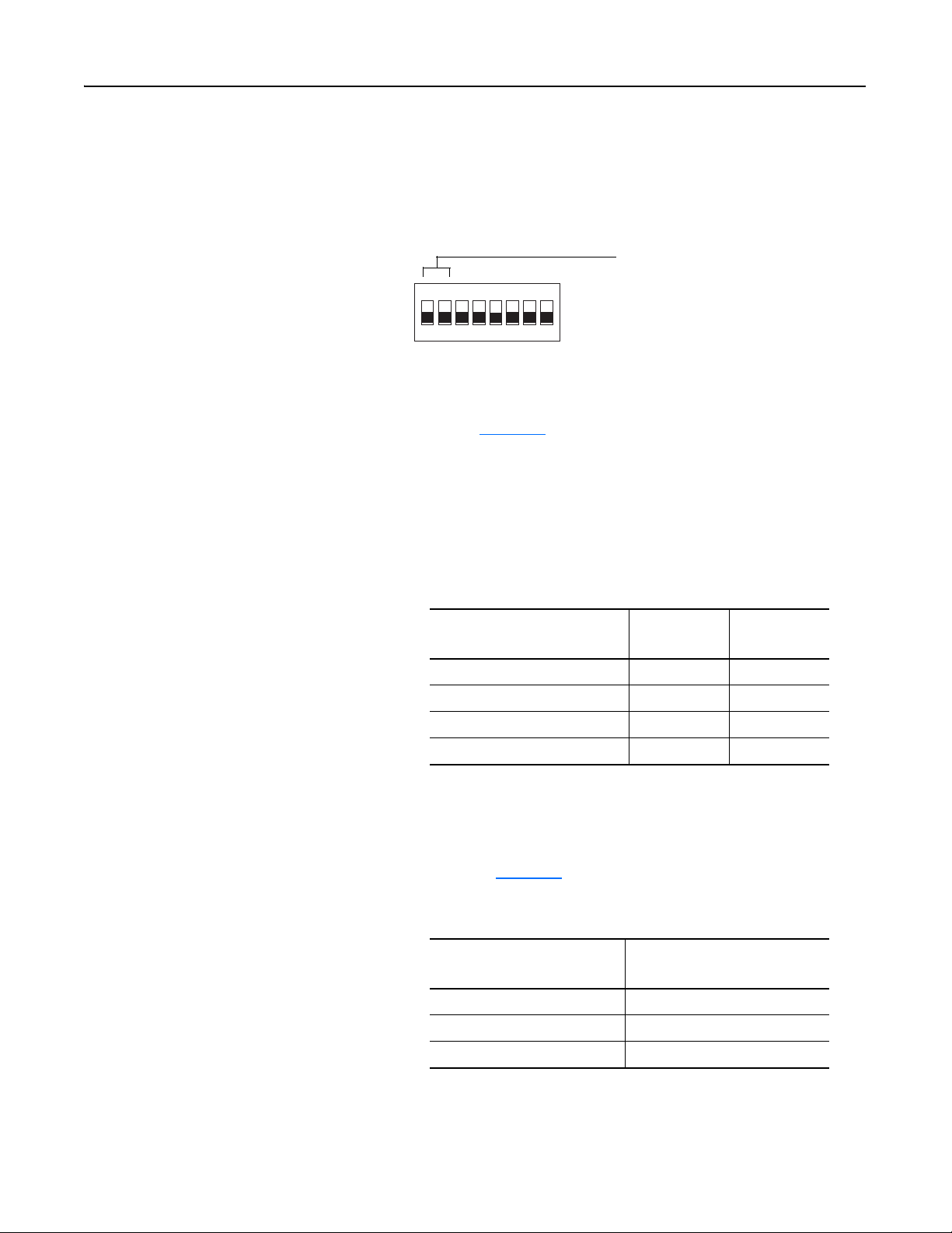
Setting the DeviceNet Node
Address
DIP switches 6 through 1 set the module’s node address using binary
addressing. The factory default setting is DeviceNet address 63.
Figure 3.6
Setting the Node Address
DeviceNet Address
12345 67 8
ON
000000 - 111111
ON = 1
OFF = 0
(0 to 63)
To set the DeviceNet node address:
1. Refer to Tab le 3. A
below for the switch settings of a specific
address.
2. Using a pointed tool, slide switches 6 through 1 to the appropriate
ON/OFF positions.
Important: When switches 7 and 8 are ON, the DeviceNet address is
set to the value in parameter P103 - [NV MAC ID].
Table 3.A Switch Settings for DeviceNet Node Addressing
DeviceNet
Address
0 000000 16 010000 32 100000 48 110000
1 000001 17 010001 33 100001 49 110001
2 000010 18 010010 34 100010 50 110010
3 000011 19 010011 35 100011 51 110011
4 000100 20 010100 36 100100 52 110100
5 000101 21 010101 37 100101 53 110101
6 000110 22 010110 38 100110 54 110110
7 000111 23 010111 39 100111 55 110111
8 001000 24 011000 40 101000 56 111000
9 001001 25 011001 41 101001 57 111001
10 001010 26 011010 42 101010 58 111010
11 001011 27 011011 43 101011 59 111011
12 001100 28 011100 44 101100 60 111100
13 001101 29 011101 45 101101 61 111101
Switch Settings
6 <---- 1
DeviceNet
Address
Switch Settings
6 <---- 1
DeviceNet
Address
Switch Settings
6 <---- 1
DeviceNet
Address
Switch Settings
6 <---- 1
14 001110 30 011110 46 101110 62 111110
15 001111 31 011111 47 101111 63 111111
Publication 0160-5.18 - June 2003
Page 23
Installation and Wiring 3-7
Setting the Baud Rate Dip switches 7 and 8 set the baud rate at which the Communication
Module communicates on the network. The factory default setting for
baud rate is 125 kbps.
Figure 3.7
Setting the Baud Rate
Use DIP Switch 8 and 7 for
12345 67 8
ON
To set the DeviceNet Baud Rate:
setting the DeviceNet Baud
Rate.
ON = 1
OFF = 0
1. Refer to Tab le 3. B
for the switch setting of a specific Baud Rate.
2. Slide switches 7 and 8 to the appropriate positions using a pointed
tool.
Important: When switches 7 and 8 are ON, the DeviceNet Baud
Rate is set to the value in parameter P104 - [NV Baud Rate].
Table 3.B Switch Settings for DeviceNet Module Baud Rate
Baud Rate
125 kbps 0 0
250 kbps 0 1
500 kbps 1 0
Set by module parameter P104 1 1
Switch Setting8 Switch Setting
7
Cable Lengths and Baud Rates
The baud rate determines the maximum length of the DeviceNet
cable. Refer to Tabl e 3.C
to determine cable lengths and baud rates.
Table 3.C Baud Rate vs. Cable Length
Baud Rate
125 kbps 500 meters (1640 feet)
250 kbps 250 meters (820 feet)
500 kbps 100 meters (328 feet)
Maximum Cable Length
(Trunk Line)
Publication 0160-5.18 - June 2003
Page 24

3-8 Installation and Wiring
Installing the Communication
Module
After setting the DIP switches, secure the Communication Module to
the drive by following these steps:
1. Insert the module, ensuring that the pins on the back of the
module line up with the drive’s expansion port.
2. Press down on the module until it is fully seated. The module is
fully seated when its sides are resting on the drive’s face.
3. Press down on the latch until it snaps into place.
Figure 3.8
Installing the Communication Module
Expansion
Port
1 2 3 4
5 6 7
1
T
U
8 9 10 11
2
T
–
D
3
T
W
V
Drive’s
Face
+
C
D
C
Publication 0160-5.18 - June 2003
Page 25
Installation and Wiring 3-9
Wiring the DeviceNet Connector Follow these recommendations for communications wiring:
•See DeviceNet Cable System Planning and Installation Manual,
Publication DN-6.7.2, for planning and installing DeviceNet
networks.
• Keep communication wiring away from high noise sources such as
motor cables.
• Increase noise immunity by:
– Using a trunk line in place of a drop line.
– Using a ferrite cable clamp around the communication line
(see Figure 3.9
).
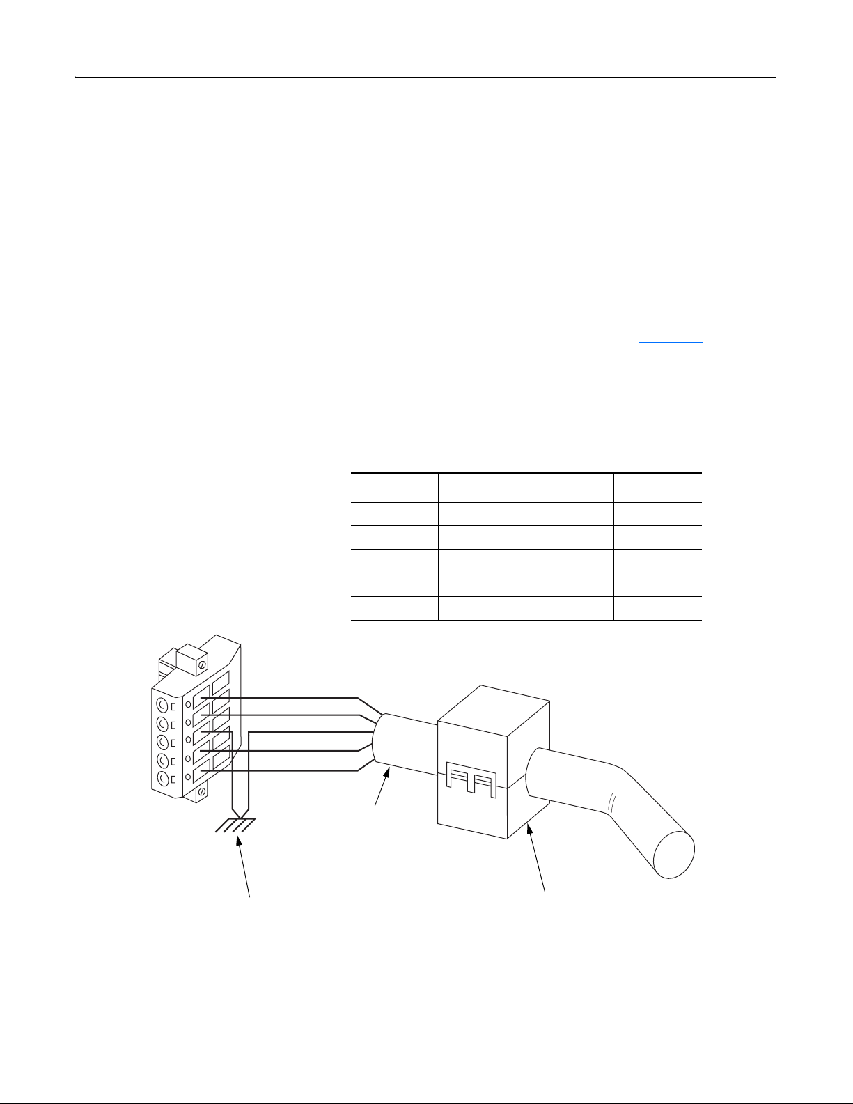
1 2 3 4 5
Red
White
Bare
Blue
Black
– Grounding the cable shield as shown in Figure 3.9
.
Figure 3.9
Wiring the DeviceNet 10-Pin Linear Plug
The Communication Module receives power and communications through the DeviceNet connector.
DeviceNet cable wires connect to the DeviceNet plug as shown below:
Color Terminal Signal Function
Black 1 COMM Common
Blue 2 CAN_L Signal Low
Bare 3 SHIELD Shield
White 4 CAN_H Signal High
Red 5 VDC+ Power Supply
DeviceNet Trunk Line
or Drop Line
Trunk line is recommended for
greatest noise immunity.
Grounding Recommendations
Attach bare wire to earth GND as close to the drive as
possible. For greatest noise immunity, drive should be
single point ground.
Important: For each DeviceNet Network with multiple
devices, only one device must be grounded.
Optional Clamp-On Ferrite Cable Clamp
Install core within 10 cm (4") of Communication
Module. Use Ferrishield (part #HI28B2039) or
Fair-Rite (part #0443164151 – quantity of 2 required).
Publication 0160-5.18 - June 2003
Page 26
3-10 Installation and Wiring
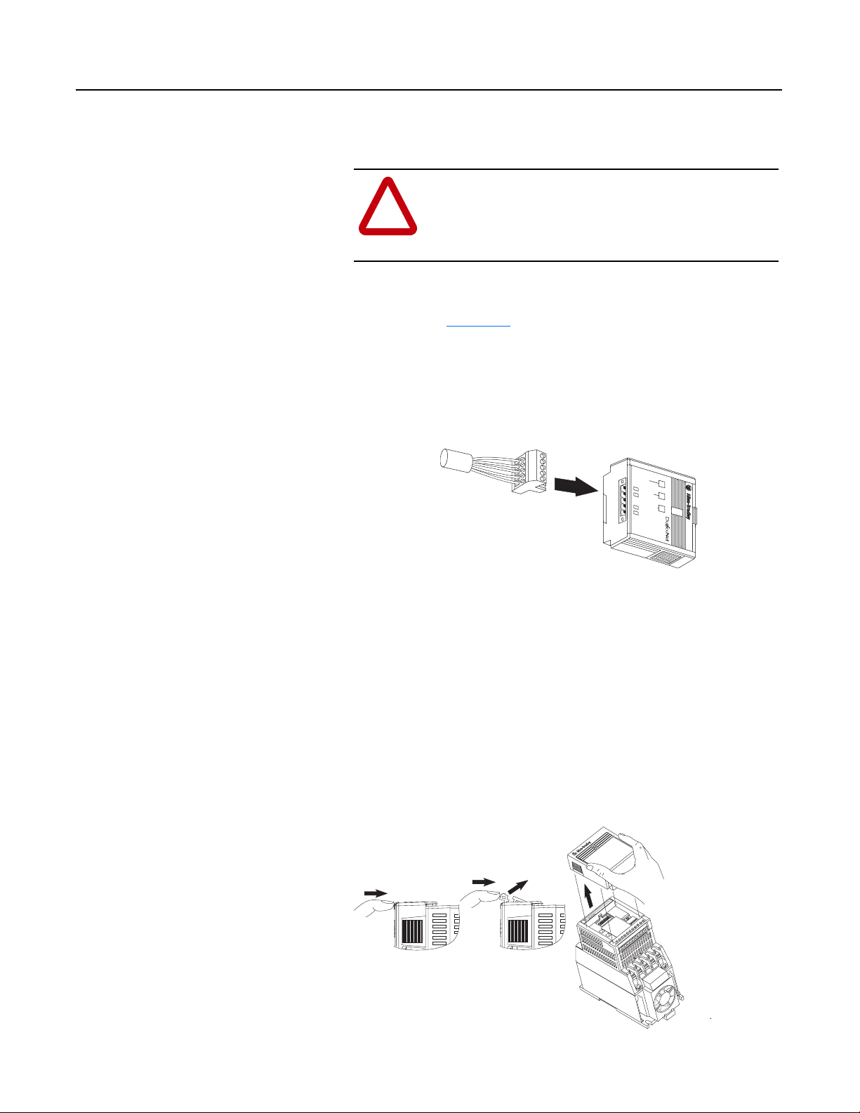
Connecting the DeviceNet Drop
Line to the Module
To connect your module DeviceNet drop line:
1. Turn off the network power supply.
ATTENTION: Do not wire the Communication
Module with the network power supply on. Wiring the
!
module with the network power supply on may short
your network or disrupt communication.
2. Make sure that the DeviceNet 10-pin Linear Plug is correctly
wired (see Figure 3.9
).
3. Locate the DeviceNet connector on the bottom of the module.
4. Insert the plug into the DeviceNet connector.
Figure 3.10
Installing the Drop Line
COMM
FAULT
READY
Removing Communication Module
From a Drive
CONFORMANCE TESTED
TM
If you need to reconfigure the Communication Module DIP switches,
you must remove the Communication Module from the drive.
1. Remove the DeviceNet plug from the Communication Module.
2. Press in on the module’s latch and then push away and up.
3. Grasp the module and pull straight up. Avoid bending or twisting
the contact pins located underneath the center portion of the
module.
Figure 3.11
Removing the Communication Module
Publication 0160-5.18 - June 2003
1 2 3 4 5 6 7 8 9 10 11
T2
T1
U
+
DC
–
DC
T3
W
V
Page 27

Chapter 4
Modes of Operation
This chapter contains information about:
• Powering up the drive with an installed 160-DN2 DeviceNet
communication module.
• Understanding the module’s modes of operation.
Before you apply power, review the Safety Precautions
page P-3
.
on Preface
Powering Up the Drive After you have installed the 160-DN2 module, apply power to the
drive and to the Network. The COMM LED should flash green or turn
solid green. If it does not, refer to Chapter 7
, Troubleshooting.
Modes of Operation The 160-DN2 module operating modes are:
• Power-up reset mode
• Run mode
• Error mode
Power-up Reset Mode
During power-up or reset, the COMM LED is off.
The 160-DN2 module follows this sequence of operation:
1. When power-up occurs, the COMM LED flashes green for 1/4
second, red for 1/4 second, and then goes blank while the 160DN2 module finishes its initialization.
2. Performs power-up initialization.
3. Reads and stores the DIP switch settings.
4. Performs a duplicate node address check to verify that another
node is not assigned the same DeviceNet address as the 160-DN2
module.
If the power-up or reset is successful, the 160-DN2 module enters the
Run mode and the COMM LED flashes green or turns solid green.
Publication 0160-5.18 - June 2003
Page 28

4-2 Modes of Operation
Modes of Operation (Continued) Power-up Reset Mode (Continued)
If the power up or reset sequence fails, the COMM LED will turn
solid red and the 160-DN2 module will enter the Error mode (see
heading below for more information).
Table 4.A COMM LED State During Power-up Reset Mode
COMM LED State Description
Flashes Green 1/4 second,
Red 1/4 second,
then goes blank
Blank Power-up initialization is taking place.
Solid Red 160-DN2 module is in Error mode. Indicates failed
Solid Green 160-DN2 module is in the Run mode.
Occurs when power is applied to module.
initialization, duplicate node address or incorrect baud rate.
Run Mode
After a successful power-up or reset, the 160-DN2 module enters the
run mode and operates as a slave device to a master device. In run
mode, the module:
• Accepts messages from the master on the DeviceNet network.
• Monitors DeviceNet incoming power.
If an error is detected, the 160-DN2 module will enter the Error mode
(see heading below for more information).
Error Mode
Publication 0160-5.18 - June 2003
If the 160-DN2 module detects an error, the COMM LED is affected.
Errors are critical or noncritical, and are summarized below.
Table 4.B COMM LED State During Error Mode
COMM LED State Error Type Description
Power-up initialization failure.
Solid Red
Flashing Red
Off
See Chapter 7
, Troubleshooting for details in the troubleshooting
Critical
(not recoverable)
Non-Critical
(recoverable)
Non-Critical
(recoverable)
Duplicate node address detected.
Incorrect baud rate.
I/O connection timed out.
DeviceNet power lost.
chart on how to recover from an error.
Page 29

Chapter 5
DeviceNet Parameter Descriptions
This chapter contains:
• a description of DeviceNet parameters
• the definition of Electronic Data Sheet (EDS) files
• Bulletin 160 SSC Interface parameters
• brief description of Bulletin 160 parameters
Important: This chapter describes the parameter set for a Series C
Bulletin 160. If you are using a Series A or Series B Bulletin 160, not
all the parameters listed in this manual may apply to that drive. When
using a Series A Bulletin 160, please refer to the Bulletin 160 SSC
User Manual, Publication 0160-5.0. When using a Series B Bulletin
160, please refer to the Bulletin 160 SSC User Manual, Publication
0160-5.9.
DeviceNet Parameters The 160-DN2 communication module contains a set of parameters
that define how the module will interact with the Bulletin 160 SSC
drive and the DeviceNet network. These parameters may be used to
set the module’s address, baud rate, and I/O data format. Parameters
may also be read to attain status from the module.
Electronic Data Sheet (EDS) Files EDS files are specially formatted ASCII files that provide all of the
information necessary for a configuration tool such as RSNetWorx
for DeviceNet to access and alter the parameters of a device. The EDS
file contains information on the number of parameters in a device and
how those parameters are grouped. Additionally, the EDS file
contains information about each parameter such as parameter min,
max, and default values, parameter data format and scaling, and the
parameter name and units.
Parameters and EDS File You select an EDS file for the Bulletin 160 drive using a software
application such as RSNetWorx for DeviceNet. (See Chapter 6
160-DN2 with DeviceNet Scanner, for instructions to select an
appropriate EDS file.) An EDS file defines all the parameters in the
Bulletin 160 drive and the 160-DN2 module, and creates a public
interface to the drive on the DeviceNet network. Configuration tools
such as RSNetWorx for DeviceNet use EDS files to present you with
parameters that enable you to configure the 160 SSC drive via
DeviceNet by changing values associated with individual parameters.
, Using
Publication 0160-5.18 - June 2003
Page 30
5-2 DeviceNet Parameter Descriptions
Parameters and EDS File
(Continued)
Parameter values may be read or written via DeviceNet. Writing a
value to a parameter may configure drive operations such as
acceleration or deceleration rates. Writing a value to a parameter may
also configure DeviceNet operations such as which input or output
assemblies are to be used for polled I/O communications with a
master. Reading a parameter value gives you status information.
Bulletin 160 SSC Interface This parameter set contains all of the parameters described in the
Bulletin 160 SSC User Manual, plus a few extra parameters to configure
the operation of the 160-DN2 module on the DeviceNet network.
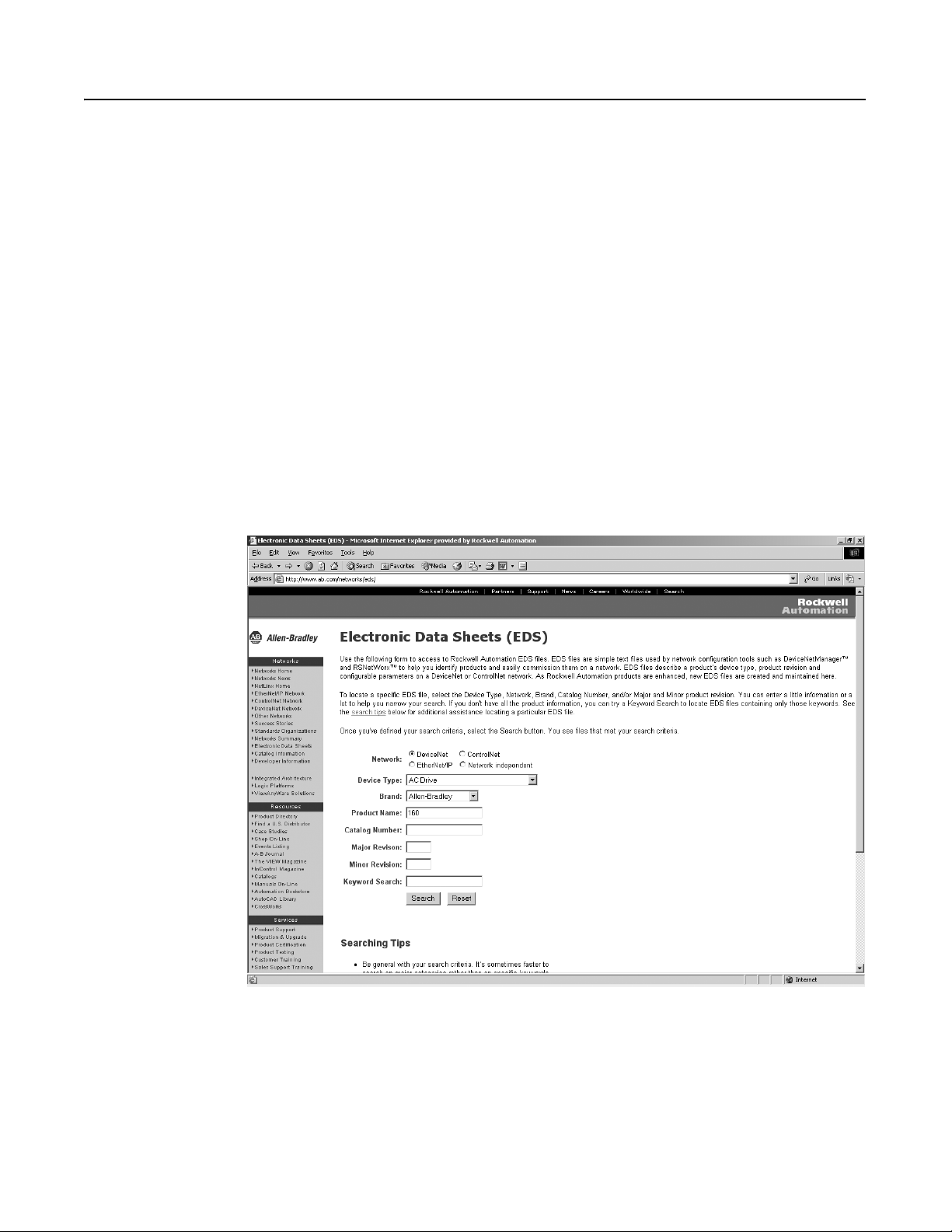
Locating EDS Files on the Internet Bulletin 160 SSC drives are available in Analog Signal Follower and
Preset Speed models. Each model supports a slightly different set of
parameters. (In general, the Preset Speed model contains extra
parameters for setting up preset speeds.) Accordingly, each drive
model uses an EDS file specific to that model.
You can find the EDS file for your drive at http://www.ab.com/
networks/eds. Select the search criteria for the EDS file to be the
same as that shown in the screen below.
Publication 0160-5.18 - June 2003
After the EDS file list appears, find your specific drive in the Product
Name column. Then, in the Brand column of that row click on the
Allen-Bradley Company link to access the EDS file for downloading.
Important: Use the correct EDS file for your specific drive model,
horsepower, and voltage. If an incorrect EDS file is used, you may not
be able to set up the drive with the configuration tool.
Page 31

DeviceNet Parameter Descriptions 5-3
Bulletin 160 SSC Interface
Parameters
The Bulletin 160 SSC Interface parameters are grouped together
logically. The following sections provide information about the
Bulletin 160 SSC Interface parameter groups:
• DeviceNet Parameters
• Drive Display Parameters
• Drive Program Parameters
The following parameter lists summarize the Bulletin 160 SSC
Interface. For more detailed information on the Display Group and
Program Group parameters, see the Bulletin 160 SSC User Manual.
Important: The following information contains object mapping data,
which is needed when using Explicit Messaging. Refer to Chapter 6,
Page 6-23
, for more information.
DeviceNet Parameters Use the following parameters to configure and monitor the DeviceNet
Network Interface. These parameters are unique to drives equipped
with the 160-DN2 DeviceNet Communication Module.
Parameter
Number
Name and Description
Object Mapping
(Class-Instance-
Attribute)
Min./Max.
Range
Factory
Default
101 [Switches MAC ID]
This read only parameter displays the state of the Node Address DIP switches.
This address may not be the current address of the module if the Baud Rate DIP
switches are set to 3. In this case P103 - [NV MAC ID] is used.
102 [Switches Baud]
This read only parameter displays the state of the Baud Rate DIP switches. A
value of 3 means that the actual baud rate used by this module is given in the
value of P104 - [NV Baud Rate].
0 = 125 kbps
1 = 250 kbps
2 = 500 kbps
3 = Use nonvolatile parameters for Address and Baud.
103 [NV MAC ID]
This read/write parameter enables you to program the Node Address of the
module independent of the DIP switch settings. To use this feature, set the baud
rate DIP switches (7 and 8) to ON before power-up. Changing this parameter
does not change the actual node address until power is cycled.
104 [NV Baud Rate]
This read/write parameter enables you to set the baud rate of the module without
having to set the DIP switches. To use this feature, set the baud rate switches (7
and 8) to ON before power up. Changing this parameter does not change the
actual data rate until power is cycled.
0 = 125 kbps
1 = 250 kbps
2 = 500 kbps
105 [Bus Off Error]
This read/write parameter determines how the Communication Module
processes a CAN Bus Off condition.
0 = Hold CAN chip in its bus off (reset) state when bus off is detected.
1 = If possible, fully reset the CAN chip and continue communicating
when a bus off condition is detected.
0xB4-1-3 0 to 63 63
0xB4-1-4 0 to 3 0
0xB4-1-5 0 to 63 63
0xB4-1-6 0 to 2 0
0x03-1-3 0 to 1 0
Publication 0160-5.18 - June 2003
Page 32

5-4 DeviceNet Parameter Descriptions
DeviceNet Parameters (Continued)
Parameter
Number
106 [Bus Off Count]
This read/write parameter counts the number of times the CAN chip went to the
bus off state. This counter stops counting when the count reaches 255. Any write
to this parameter will reset the counter to 0.
107 [Output Assembly]
This read/write parameter sets the output assembly instance that is to be used
for polled messaging with the master. The output assembly defines the data
format that the drive receives from the master. The name (output assembly) is
somewhat misleading in that this parameter determines the format of data being
sent to the drive by the master. It is named output assembly because the
DeviceNet specification refers to all assemblies as they relate to the master. The
following assembly instances are valid for this parameter:
0 = No Data
1 = Basic Contactor Output
2 = Two Command Contactor Output
3 = Basic Overload Output
4 = Basic Motor Control Output
5 = 2 Command Motor Control
20 = Basic Speed Control
21 = Extended Speed Control
100 = Speed Control in Hz
101 = Preset Control (for Preset Speed units only)
103 = Allen-Bradley Drive Assembly
Important: See Appendix B, pages B-24
assembly.
Name and Description
to B-25 for the formats of the output
Object Mapping
(Class-Instance-
Attribute)
0x03-1-4 0 to 255 0
0x29-1-100 0 to 103 20
Min./Max.
Range
Factory
Default
108 [Input Assembly]
This read/write parameter sets the input assembly instance that is to be used for
polled messaging with the master. The input assembly defines the data format that
the drive sends to the master in response to a polled message from the master.
The name (input assembly) is somewhat misleading in that this parameter
determines the format of data being sent to the master. It is named input assembly
because the DeviceNet specification refers to all assemblies as they relate to the
master. The following assembly instances are valid for this parameter:
0 = No Data
50 = Basic Overload Input
51 = Extended Overload Input
52 = Basic Motor Control Input
53 = Extended Motor Control Input
54 = Extended Motor Control 2
70 = Basic Speed Control Input
71 = Extended Speed Control Input
102 = Custom Parameter Based Assembly
104 = Allen-Bradley Drive Assembly
105 = Allen-Bradley Drive Assembly with Parameters
Important: See Appendix B, pages B-26
assembly.
109 [Assembly Word 0]
This read/write parameter is used when P108 - [Input Assembly] is set to 102
Custom Parameter Based Assembly. It defines the first word in an assembly built
from Bulletin 160 parameters. A 0 value defines the end of the assembly. For
more information, see Appendix B, page B-27
0x29-1-101 0 to 105 70
to B-28 for the formats of the input
0xB4-1-7 0 to 88 9
.
Publication 0160-5.18 - June 2003
Page 33

DeviceNet Parameters (Continued)
DeviceNet Parameter Descriptions 5-5
Parameter
Number
110 [Assembly Word 1]
This read/write parameter is used when P108 - [Input Assembly] is set to 102
Custom Parameter Based Assembly. It defines the second word in an assembly
built from Bulletin 160 parameters. A 0 value defines the end of the assembly. For
more information, see Appendix B, page B-27
111 [Assembly Word 2]
This read/write parameter is used when P108 - [Input Assembly] is set to 102
Custom Parameter Based Assembly, or 105 Allen-Bradley Drive Assembly with
Parameters. It defines the third word in an assembly built from Bulletin 160
parameters. A 0 value defines the end of the assembly. For more information, see
Appendix B, page B-27 or B-28.
112 [Assembly Word 3]
This read/write parameter is used when P108 - [Input Assembly] is set to 102
Custom Parameter Based Assembly, or 105 Allen-Bradley Drive Assembly with
Parameters. It defines the fourth word in an assembly built from Bulletin 160
parameters. A 0 value defines the end of the assembly. For more information, see
Appendix B, page B-27 or B-28.
113 [DN Fault Mode]
This read/write parameter determines the drive’s behavior when a
communication fault such as loss of DeviceNet power occurs. The behavior
choices are:
0 = Fault the drive and issue a stop command
1 = Ignore the communication fault
Name and Description
.
Object Mapping
(Class-Instance-
Attribute)
0xB4-1-8 0 to 88 0
0xB4-1-9 0 to 88 0
0xB4-1-10 0 to 88 0
0x29-1-16 0 to 1 0
Min./Max.
Range
Factory
Default
!
114 [Motor Base RPM]
This read/write parameter is set to the motor’s rated nameplate speed in RPM.
115 [DNet Idle Mode]
This Parameter controls the action of the drive when the Scanner is in Idle Mode.
0 = Stop if Idle Mode (default)
1 = Hold last state if Idle Mode
116 [DNet SW Version]
This read only parameter indicates the software version of the DeviceNet option.
The number is shown in the format xx.yy where xx denotes the major revision
level and yy denotes the minor revision level.
117 [COS Mask]
This parameter is a 16-bit mask used to enable automatic change of state
messages. A 0 disables the indicated status from causing an automatic
message. A 1 enables the status. The mask is applied to the defined input status
assembly. The default value is 0xFFFF.
118 [Local Return Md]
This parameter sets the input mode the drive will use when transitioning from
network to local control. This is only used with input mode 2. Available values are
0, 1, 3, 4, and 5.
ATTENTION: Ignoring communication faults may result in
equipment damage, personal injury, or death. Make sure you
understand how ignoring a communication fault affects the
operation of your system.
0x28-1-15 200 to 32000 1800 RPM
0xB4-1-11 0 to 1 0
0xB4-1-12 0.00 to 10.00 3.01
0xB4-1-13 0 to 0xFFFF 0xFFFF
0xB4-1-14 0 to 9 0
Publication 0160-5.18 - June 2003
Page 34

5-6 DeviceNet Parameter Descriptions
Drive Display Parameters
(Read Only)
Parameter
Number
Parameter Name
Object Mapping
(Class-Instance-
Attribute)
Below is a brief description of the Bulletin 160 SSC Interface Display
Group parameters. Refer to the Bulletin 160 SSC User Manual for
more detailed information on these parameters
Description Units
.
01 [Output Frequency] 0xB3-1-1 Frequency at TB2 terminals T1, T2, T3. 0.1 Hz
02 [Output Voltage] 0xB3-1-2 Voltage at TB2 terminals T1, T2, T3. 1 Volt
03 [Output Current] 0xB3-1-3 Current at TB2 terminals T1, T2, T3. 0.01 Amperes
04 [Output Power] 0xB3-1-4 Power at TB2 terminals T1, T2, T3. 0.01 kW
05 [Bus Voltage] 0xB3-1-5 DC Bus voltage level. 1 Volt
06 [Cmd Frequency] 0xB3-1-6 Commanded Frequency. 0.1 Hz
07 [Present Fault] 0xB3-1-7 Coded last fault number. Numeric Value
08 [Heatsink Temp] 0xB3-1-8 Temperature of the drive heatsink. 1 degree C
09 [Drive Status] 0xB3-1-9 Status of drive in binary coded format. Important: Parameter 9
Binary Number
shown below does not match what is published in the Bulletin 160
SSC User Manual. The DeviceNet binary code for Parameter 9 is:
Bit 6 Bit 5 Bit 4
Bit 3 Bit 2 Bit 1 Bit 0
Running
Forwa rd
Accel
Decel
Drive
Fau lted
Reverse
Latched
A-B Internal
Use Only
At
Frequency
Reference
10 [Drive Type] 0xB3-1-10 Used by Allen-Bradley field ser vice personnel. Numeric Value
11 [Firmware Version] 0xB3-1-11 Version of drive firmware used. Numeric Value
12 [Input Status]
➀ 0xB3-1-12 Open (0) Closed (1) state of Drive’s discrete inputs.
Binary Number
Important: Parameter 12 shown below does not match what is
published in the Bulletin 160 SSC User Manual. The DeviceNet
binary code for Parameter 12 is:
Bit 6 Bit 5 Bit 4Bit 7
Bit 3 Bit 2 Bit 1 Bit 0
Preset 1
Input
Preset 2
Input
Preset 3
Input
Unused
Reverse
Stop
Start
Not Used
13 [Power Factor Ang] 0xB3-1-13 Angle (electrical degrees) between V and I. 0.1 degree C
14 [Memory Probe] 0xB3-1-14 Used by Allen-Bradley service personnel. Numeric Value
➀ For preset speed model, this parameter contains the data from parameter 15 in the SSC drive due to conflicting parameter numbers with DeviceNet
specific parameters.
Publication 0160-5.18 - June 2003
Page 35

DeviceNet Parameter Descriptions 5-7
Drive Display Parameters
(Read Only) (Continued)
Parameter
Number
Parameter Name
15 [Preset Status] 0xB3-1-15 Open (0) and closed (1) state of TB3 inputs SW1, SW2, and SW3. Binary Number
16 [Analog Input] 0xB3-1-16 The analog input as a percent of full scale. 0.1%
17 [Fault Buffer 0] 0xB3-1-17 Most recent fault. Numeric Value
18 [Fault Buffer 1] 0xB3-1-18 Second most recent fault. Numeric Value
19 [Fault Buffer 2] 0xB3-1-19 Third most recent fault. Numeric Value
This parameter applies only to the Analog Signal Follower model.
This parameter applies only to the Preset Speed model.
Object Mapping
(Class-Instance-
Attribute)
Description Units
Bit 3 Bit 2 Bit 1 Bit 0
SW1
SW2
SW3
Unused
Publication 0160-5.18 - June 2003
Page 36

5-8 DeviceNet Parameter Descriptions
Drive Program Parameters Below is a brief description of the Bulletin 160 SSC Interface
Program Group parameters. Refer to the Bulletin 160 SSC User
Manual for more detailed information on these parameters.
Parameter
Number
30 [Accel Time 1] 0xB3-1-30 Time to ramp from 0 Hz to maximum frequency. 0.1 Seconds
31 [Decel Time 1] 0xB3-1-31 Time to ramp from maximum frequency to 0 Hz. 0.1 Seconds
32 [Minimum Frequency] 0xB3-1-32 Lowest continuous output frequency. 1 Hz
33 [Maximum Frequency] 0xB3-1-33 Highest continuous output frequency. 1 Hz
34 [Stop Mode Select] 0xB3-1-34 Determines stop mode used. Numeric Value
35 [Base Frequency] 0xB3-1-35 Set to motor’s nameplate frequency. 1 Hz
36 [Base Voltage] 0xB3-1-36 Set to motor’s nameplate voltage. 1 Volt
37 [Maximum Voltage] 0xB3-1-37 Highest voltage the drive will output. 1 Volt
38 [Boost Select] 0xB3-1-38 Sets the volts/Hz relationship. Numeric Value
39 [Skip Frequency] 0xB3-1-39 Frequency at which drive will not run continuously. 1 Hz
40 [Skip Freq Band] 0xB3-1-40 Used with P39 - [Skip Frequency] to create skip band. 1 Hz
41 [Overload Select] 0xB3-1-41 Selects derating factor for motor overload. Numeric Value
42 [Motor Overload] 0xB3-1-42 Set to motor nameplate full load amperes. 0.01 Amperes
43 [Current Limit] 0xB3-1-43 Max output current allowed before limiting. % I rating
44 [DC Hold Time] 0xB3-1-44 DC Injection Braking duration. 0.1 Seconds
45 [DC Hold Voltage] 0xB3-1-45 Voltage level for DC Injection Braking. 1 Volt
46 [Input Mode] 0xB3-1-46 Type of START, STOP, REV, commands. Numeric Value
Parameter Name
Object Mapping
(Class-Instance-
Attribute)
Description Units
ATTENTION: Changing this parameter
value may cause unpredictable network
!
conditions, resulting in equipment damage,
personal injury, or death. Make sure that
you understand how changing this
parameter affects your application.
ATTENTION: Changing this parameter
value may cause unpredictable network
!
47 [Output Configure] 0xB3-1-47 Configures TB3 output relay functionality. Numeric Value
48 [Output Threshold] 0xB3-1-48 Used in conjunction with P47 - [Output Configure]. Numeric Value
49 [PWM Frequency] 0xB3-1-49 Carrier frequency for PWM output waveform. 0.1 kHz
50 [Restart Tries] 0xB3-1-50 Times drive will attempt to reset a fault. Numeric Value
51 [Restart Time] 0xB3-1-51 Time between restart attempts. 0.1 Seconds
52 [DB Enable] 0xB3-1-52 Enables/disables dynamic braking. Numeric Value
53 [S-Curve] 0xB3-1-53 Enables a fixed shape S-curve. Numeric Value
Publication 0160-5.18 - June 2003
conditions, resulting in equipment damage,
personal injury, or death. Make sure that
you understand how changing this
parameter affects your application.
Page 37

DeviceNet Parameter Descriptions 5-9
Drive Program Parameters
(Continued)
Parameter
Number
54 [Clear Fault] 0xB3-1-54 Setting to 1 performs a fault reset. Numeric Value
55 [Probe Address] 0xB3-1-55 Used by Allen-Bradley service personnel. Numeric Value
56 [Reset Functions] 0xB3-1-56 Sets all parameters to their factory default. Numeric Value
57 [Program Lock] 0xB3-1-57 Locks all program group parameters. Numeric Value
58 [Internal Freq] 0xB3-1-58 Digital frequency setpoint. 0.1 Hz
59 [Freq Select] 0xB3-1-59 Selects source of Frequency command. Numeric Value
60 [Zero Offset] 0xB3-1-60 Add or subtracts an offset to the analog input. Numeric Value
60 [DN Preset Cmd] 0xB3-1-92 Network preset command. Numeric Value
61 [Preset Freq 0] 0xB3-1-61 Sets command frequency when selected. 0.1 Hz
62 [Preset Freq 1] 0xB3-1-62 Sets command frequency when selected. 0.1 Hz
63 [Preset Freq 2] 0xB3-1-63 Sets command frequency when selected. 0.1 Hz
64 [Preset Freq 3] 0xB3-1-64 Sets command frequency when selected. 0.1 Hz
65 [Preset Freq 4] 0xB3-1-65 Sets command frequency when selected. 0.1 Hz
66 [Preset Freq 5] 0xB3-1-66 Sets command frequency when selected. 0.1 Hz
67 [Preset Freq 6] 0xB3-1-67 Sets command frequency when selected. 0.1 Hz
68 [Preset Freq 7] 0xB3-1-68 Sets command frequency when selected. 0.1 Hz
69 [Accel Time 2] 0xB3-1-69 Sets second acceleration rate. 0.1 Seconds
70 [Decel Time 2] 0xB3-1-70 Sets second deceleration rate. 0.1 Seconds
71 [IR Compensation] 0xB3-1-71 Adds a voltage to the output based on the torque current. 1%
72 [Slip Comp] 0xB3-1-72 Compensates for the inherent slip of the motor. 0.1 Hz
73 [Reverse Disable] 0xB3-1-73 Setting to 1 disables the reverse. Numeric Value
74 [Analog Select] 0xB3-1-74 Selects between unipolar and bipolar analog input. Numeric Value
75 [Analog Minimum] 0xB3-1-75 Sets the percent of the analog input used to represent
76 [Analog Maximum] 0xB3-1-76 Sets the percent of the analog input used to represent
78 [Compensation] 0xB3-1-78 Some drive/motor combinations have inherent instabilities
79 [Curent Trip] 0xB3-1-79 Percent above P43 - [Current Limit] at which the drive trips
Parameter Name
Object Mapping
(Class-Instance-
Attribute)
Description Units
0.1%
P32 - [Minimum Frequency].
0.1%
P33 - [Maximum Frequency].
Numeric Value
which are exhibited as non-sinusoidal motor currents. A
setting of 1 will enable the compensation to correct this
condition. A setting of 0 disables this function.
1%
immediately.
This parameter applies only to the Analog Signal Follower model.
This parameter applies only to the Preset Speed model.
Publication 0160-5.18 - June 2003
Page 38

5-10 DeviceNet Parameter Descriptions
Drive Program Parameters
(Continued)
Parameter
Number
80 [Stall Disable] 0xB3-1-80 Amount of time that the drive must be in a stall condition
81 [Proc Kp Gain] 0xB3-1-81 Proportional gain used by the PI regulator. This parameter is
82 [Proc Ki Gain] 0xB3-1-82 Integral gain used by the PI regulator. This parameter is
83 [Proc Reference] 0xB3-1-83 Set point value to which PI control will regulate. This
84 [PI Dead Band] 0xB3-1-84 The PI control will ignore errors less than this value. This
Parameter Name
Object Mapping
(Class-Instance-
Attribute)
Description Units
before it causes a stall fault.
ATTENTION: Risk of equipment damage
exists. Continuous operation at high
!
active when P46 - [Input Mode] setting 9 is used.
active when P46 - [Input Mode] setting 9 is used.
parameter is active when P46 - [Input Mode] setting 9 is
used.
parameter is active when P46 - [Input Mode] setting 9 is
used.
currents caused by a stall can cause motor
damage.
Numeric Value
Numeric Value
Numeric Value
Numeric Value
Numeric Value
This parameter applies only to the Analog Signal Follower model.
This parameter applies only to the Preset Speed model.
Publication 0160-5.18 - June 2003
Page 39

Chapter 6
Using 160-DN2 with DeviceNet Scanner
This chapter provides an overview of how to use the Bulletin 160DN2 Communication Module with a DeviceNet Scanner. Scanners
act as “Masters” on a DeviceNet Network for the I/O communication
with a 160-DN2 module. Scanners periodically send I/O messages to
a 160-DN2 module at a set frequency, and the module responds to
these I/O messages by sending status messages back to the scanner.
The scanner also allows a ladder logic program to configure and read
parameters from the Bulletin 160 SSC drive through special encoded
instructions called Explicit Messages.
This chapter contains information on:
• How to create the EDS file for the 160-DN2 module.
• How to set up the 160-DN2 module on DeviceNet.
• How to select Input and Output Assemblies for I/O messaging.
• How to set up a scanner (1756-DNB, 1771-SDN or 1747-SDN) to
work with the 160-DN2 module.
• Sample ladder logic programs for ControlLogix, PLC-5, and SLC
controllers to control the Bulletin 160 SSC drive using I/O
messaging.
• How to set up Explicit Messaging, and sample ladder logic
programs for ControlLogix, PLC-5, and SLC controllers to
execute Explicit Messaging.
Before continuing this chapter, we recommend that you read the
RSNetWorx for DeviceNet Getting Results Guide Online help
(installed with the software) and the DeviceNet Scanner Module
Installation Instructions Manual for the scanner being used.
Understanding the concepts in these manuals will be important to
using the information in this chapter.
This chapter includes examples for using the 160-DN2 module with a
1756-DNB Scanner/ControlLogix system, 1771-SDN Scanner/PLC-5
system, and 1747-SDN Scanner/SLC system.
Important: All examples in this chapter use a Bulletin 160 SSC
Series C preset speed drive, RSLinx Software (version 2.3x or
higher), RSNetWorx for DeviceNet Software (version 3.xxx or
higher), RSLogix Programming Software and, for ControlLogix,
Ethernet via the controller backplane.
Publication 0160-5.18 - June 2003
Page 40

6-2 Using 160-DN2 with DeviceNet Scanner
Needed Tools The following tools are needed to set up the 160-DN2 module on a
DeviceNet network and operate with a scanner:
• RSLinx Software (version 2.3x or higher)
• RSNetWorx for DeviceNet (version 3.xxx of higher)
• RSLogix Programming Software
Setting Device MAC ID’s Every device on a DeviceNet network must have a unique MAC ID
between 0 and 63. Use the network and a configuration tool such as
RSNetWorx for DeviceNet to set the MAC ID on the scanner. You
can set the MAC ID for the 160-DN2 communication module using
this same method or by using its DIP switches. For directions on
setting the 160-DN2 module MAC ID, refer to Chapter 3
.
Using RSNetWorx for DeviceNet Going Online
Before starting, make sure to configure the proper driver in RSLinx. If
you need further assistance, refer to the online Help in RSLinx.
You can view the devices on a DeviceNet network by going online. A
Shortcut to
RSNetWorx
device may appear as an unrecognized device (node 63 in Figure 6.1
if RSNetWorx for DeviceNet does not have an EDS file for it.
)
1. After setting up a driver in RSLinx, start RSNetWorx for DeviceNet.
2. Select Network > Online. If the Browse for Network dialog box
appears, RSLinx has multiple drivers configured. Select your
DeviceNet network, and click OK. A prompt appears.
3. Click OK to go online. The devices on the network appear in the
Configuration View. You can select Graph, Spreadsheet or
Master/Slave views. Figure 6.1
shows an example network in a
Graph view.
Figure 6.1
Example DeviceNet Network in Graph View
Publication 0160-5.18 - June 2003
Page 41

Using 160-DN2 with DeviceNet Scanner 6-3
Using RSNetWorx for DeviceNet
(Continued)
Creating an EDS File
If the 160-DN2 communication module and Bulletin 160 SSC drive
appear as an unrecognized device, create an EDS file for it.
1. Right-click the “Unrecognized Device” icon, and select Register
Device in the menu. The EDS Wizard (Figure 6.2
2. Click Next to display the next step.
3. Select Upload EDS, and then click Next.
4. Type a description (if desired), and then click Next.
5. Under Polled, select Enabled, type 4 in the Input Size and Output
Size boxes, and then click Next. RSNetWorx will upload the EDS
file from the drive and communication module.
6. Click Next to display the icon options for the node. We
recommend that you use the icon for your product. You can
change icons by clicking Change Icon.
7. Click Next to view a summary, and then click Next again to
accept it.
) appears.
8. Click Finish to finish the EDS creation. A new icon represents
the drive and 160-DN2 module in the Configuration View.
Figure 6.2
EDS Wizard Screen
Publication 0160-5.18 - June 2003
Page 42

6-4 Using 160-DN2 with DeviceNet Scanner
Using RSNetWorx for DeviceNet
(Continued)
Accessing and Editing Parameters
Parameters in the drive and 160-DN2 module can be edited with
RSNetWorx for DeviceNet.
1. After creating an EDS file, right-click on the icon for the Bulletin
160 SSC drive and 160-DN2 module and select Properties. The
Bulletin 160 Drive dialog box appears.
2. Click the Parameters tab (Figure 6.3
appears, click Upload to load the parameter values in the drive to
the computer.
Parameters are displayed in numerical order under Parameter.
You can either scroll through the list, or check the Groups box
and select a specific group of parameters. The available groups
and the numbers of the module parameters will vary based on the
type of drive that is connected to the module.
3. In the Current Value column, double-click a value to edit it.
4. Click Apply to save changes to the device.
Figure 6.3
Example Bulletin 160 Drive Dialog Box
). If an EDS Editor message
Publication 0160-5.18 - June 2003
Page 43

Using 160-DN2 with DeviceNet Scanner 6-5
Selecting Input and Output
Assemblies for I/O Messaging
The DeviceNet Specification defines Assembly Objects as objects
that “bind attributes of multiple objects to allow data to or from each
object to be sent over a single connection.” The 160-DN2 module
uses Assembly Objects to send data to and from a Scanner over an I/O
connection. The terms input and output are defined from the scanner’s
point of view. Therefore, Output Assemblies are information that is
output from the scanner and consumed by the 160-DN2 module.
Input Assemblies are the status information produced by the module
and consumed as input by the scanner.
The 160-DN2 module lets you select between various Input and
Output Assemblies, thereby choosing the data format of the messages
that are passed back and forth between the module and the scanner on
the I/O connection. The Assemblies that are supported are numbered
and are part of a DeviceNet-defined “Motor Control Hierarchy.” This
lets drives directly replace motor starters or contactors on a network
without the need to reprogram the scanner. Refer to Appendix B,
pages B-23
to B-28 for information on the data format of all Bulletin
160 Assemblies.
DeviceNet parameters P107 - [Output Assembly] and P108 - [Input
Assembly] must be programmed with the proper output or input
assembly. Refer to Chapter 5, Page 5-4
for available selections.
Use the information that is appropriate to your particular system to
determine which Input and Output Assembly to use. See Appendix
B
for descriptions of all Input and Output Assemblies.
To illustrate how to select the Assemblies, we will use Output
Assembly 103 and Input Assembly 104 as examples. The data formats
for these Assemblies are:
Table 6.A Output Assembly 103 Data Format
Byte Bit 7 Bit 6 Bit 5 Bit 4 Bit 3 Bit 2 Bit 1 Bit 0
0 N/A N/A Direction Direction Clear Faults N/A Start Stop
1N/AReference
Select
2 Scale Speed Reference (Low Byte)
3 Scale Speed Reference (High Byte)
Byte Bit 7 Bit 6 Bit 5 Bit 4 Bit 3 Bit 2 Bit 1 Bit 0
0 Fault N/A Decel Accel Rot Dir Cmd Dir Running Enabled
1Freq
Source
2 Actual Speed Reference 0-32767
3 Actual Speed Reference 0-32767
Freq
Source
Reference
Select
Table 6.B Input Assembly 104 Data Format
Freq
Source
Reference
Select
Freq
Source
N/A N/A N/A N/A
Local Local Local At Speed
Publication 0160-5.18 - June 2003
Page 44

6-6 Using 160-DN2 with DeviceNet Scanner
Selecting Input and Output
Assemblies for I/O Messaging
(Continued)
An example screen (Figure 6.4) shows Output Assembly 103 and
Input Assembly 104 selected. The following steps were used:
Changing the Output Assembly
1. In the Current Value column, double-click on the value for
Parameter 107 - [Output Assembly].
2. Enter Assembly Number “103.”
3. Click Apply to save the changes.
Changing the Input Assembly
1. In the Current Value column, double-click on the value for
Parameter 108 - [Input Assembly].
2. Enter Assembly Number “104.”
3. Click Apply to save the changes.
Figure 6.4
Example Input and Output Assemblies Screen
Publication 0160-5.18 - June 2003
Page 45

Using 160-DN2 with DeviceNet Scanner 6-7
Enabling Network Control The 160-DN2 module must be configured to accept commands from
the network. To do this, configure the drive “Input Mode” parameter
(Figure 6.5
Configuring Drive Input Mode
1. In the Current Value column, click on the value for Parameter 46
- [Input Mode] and select “Network Control” from the dropdown
list.
Important: Remember to jumper or close drive Terminals 7 and
8 on TB2 before the drive can start.
2. Click Apply to save the changes.
).
ATTENTION: Changing this parameter value may
cause unpredictable network conditions, resulting in
!
equipment damage, personal injury, or death. Ensure
that you understand how changing this parameter
affects your application.
Figure 6.5
Network Control Screen
Publication 0160-5.18 - June 2003
Page 46

6-8 Using 160-DN2 with DeviceNet Scanner
Enabling Network Control
(Continued)
For the new input mode to take effect, modify the drive “Reset
Functions” parameter (Figure 6.6
).
Modifying Drive Reset Functions
1. In the Current Value column, click on the value for P56 - [Reset
Functions] and select “Reset Input Mode” from the dropdown
list.
2. Click Apply to save the changes.
Figure 6.6
Reset Input Mode Screen
Publication 0160-5.18 - June 2003
Page 47

Using 160-DN2 with DeviceNet Scanner 6-9
Configuring the 160 to Accept
Speed Commands from the
Network
The 160-DN2 module must be configured to accept its speed
commands from the network. To do this, change the drive “Frequency
Select” parameter (Figure 6.7
).
1. In the Current Value column, click on the value for P59 -
[Frequency Select] and select “Internal Freq” from the
dropdown list.
2. Click Apply to save the changes.
3. Click OK to close the window.
Figure 6.7
Frequency Select Screen
Publication 0160-5.18 - June 2003
Page 48

6-10 Using 160-DN2 with DeviceNet Scanner
Configuring the Scanner The scanner must be configured to communicate with the 160-DN2
module and connected Bulletin 160-SSC drive.
Example Network
After the module is configured, the connected drive and module
become a single node on the network. This section provides a step-bystep procedure to configure the scanner in a network, such as the
simple network example shown in Figure 6.8
configure the drive for using the example Output Assembly 103 and
Input Assembly 104.
Figure 6.8
Example DeviceNet Network
. In our example, we will
MAC ID 0
(Node 0)
SLC 500 Controller with
1747-SDN Scanner
MAC ID 62
(Node 62)
Computer with 1770-KFD and
RSNetWorx for DeviceNet
MAC ID 1
(Node 1)
Bulletin 160-SSC
and 160-DN2
Publication 0160-5.18 - June 2003
Page 49

Using 160-DN2 with DeviceNet Scanner 6-11
Configuring the Scanner
(Continued)
Setting Up the Scan List
For the scanner to communicate with a drive, the scanner must be
configured and the drive’s node number must be added to its scan list.
1. Go online with RSNetWorx for DeviceNet. The devices on the
network are displayed in the configuration view.
Figure 6.9
Configuration View (Graph)
2. Right-click the DeviceNet scanner (MAC ID 00 in Figure 6.9)
and select Properties. The Scanner Module dialog box appears.
Important: If your scanner is an unrecognized device, you must
create an EDS file for it and then configure the scanner. Create an
EDS file by following the instructions using the EDS Wizard (see
Page 6-3
for details). Configure the scanner using the General and
Module tabs. If you need more information, click Help or refer to
your scanner documentation.
3. Click the Scanlist tab. A message box prompts you to upload.
4. Click Upload. Data is uploaded from the scanner, and then the
Scanlist page (Figure 6.10
) appears.
5. Click the Automap on Add box (a check mark will appear).
6. In the “Available Devices” list, select the drive, and then click >
(Right Arrow) to move it to the “Scanlist.”
Publication 0160-5.18 - June 2003
Page 50

6-12 Using 160-DN2 with DeviceNet Scanner
Configuring the Scanner
(Continued)
Figure 6.10
Scanlist Page in the Scanner Module Dialog Box
7. In the “Scanlist,” select the drive, and then click Edit I/O Param-
eters. The Edit I/O Parameters dialog box (Figure 6.11
Figure 6.11
Edit I/O Parameters Dialog Box
) appears.
8. Select the type(s) of data exchange (Strobed, Polled, Change of
State or Cyclic). In our example, we selected Polled.
Publication 0160-5.18 - June 2003
Page 51

Using 160-DN2 with DeviceNet Scanner 6-13
Configuring the Scanner
(Continued)
9. Type the number of bytes that are required for your I/O in the
Input Size and Output Size boxes.
Refer to Appendix B, pages B-23
to B-28 for all Bulletin 160
Assemblies.
In our example, we typed “4” in the Input Size and Output Size
boxes because we are using Output Assembly 21 and Input
Assembly 71.
10. Set the required rate for the data exchange selected in step 8.
(Click Help for more information.)
Data Exchange Rate to Set
Strobed N/A
Polled Poll Rate
Change of State Heartbeat Rate
Cyclic Send Rate
In our example using Polled data exchange, we selected “Every
Scan” for the Poll Rate.
11. Click OK. If you changed any settings, a Scanner Applet asks if it
is OK to unmap the I/O. Click Ye s to continue. The Edit I/O
Parameters dialog box closes and then the Scanner Module dialog
box (Figure 6.10
) reappears. You will map the I/O in the next
section in this chapter.
Mapping the Drive Data in the Scanner
Data from I/O messages must be mapped in the scanner. This
mapping determines where a ladder logic program can find data that
is passed over the network. You must map both the Input I/O and the
Output I/O.
Mapping the Input I/O
1. In the Scanner Module dialog box, click the Input tab. (If
necessary, right-click the scanner in the configuration view
(Figure 6.9) to display this dialog box.)
Publication 0160-5.18 - June 2003
Page 52

6-14 Using 160-DN2 with DeviceNet Scanner
Configuring the Scanner
(Continued)
Figure 6.12
Input Page on the Scanner Module Dialog Box
If you selected the Automap on Add box in the Scanlist tab (Figure
6.10), RSNetWorx has already mapped the I/O. If it is not mapped,
click Automap to map it. If you need to change the mapping, click
Advanced and change the settings. Click Help for assistance.
2. In the Memory box, select a location in scanner memory.
Scanner Memory Locations
1747-SDN Discrete or M-File
1756-DNB Assembly Data
1771-SDN Block Xfer 62 – 57
In our example, we are using a 1756-DNB scanner and selected
Assembly Data.
3. In the Start DWord box, select the word in memory at which the
data should start. In our example, we selected 0. Due to the 32-bit
data used by the 1756-DNB scanner in our example, the Logic
Status and Speed Feedback information are combined in address
1:I.Data[0], where 1 equals the slot number of the scanner.
Therefore, the Logic Status is defined by bits 0-15 (least
significant word), and the Speed Feedback is defined by bits 1631 (most significant word).
Publication 0160-5.18 - June 2003
Page 53

Using 160-DN2 with DeviceNet Scanner 6-15
Configuring the Scanner
(Continued)
Mapping the Output I/O
1. In the Scanner Module dialog box, click the Output tab. To
display this dialog box, right-click the scanner in the
configuration view (Figure 6.9
Figure 6.13
Output Page on the Scanner Module Dialog Box
).
If you selected the Automap on Add box in the Scanlist tab
(Figure 6.10
), RSNetWorx has already mapped the I/O. If it is not
mapped, click Automap to map it. If you need to change the
mapping, click Advanced and change the settings. Click Help for
assistance.
2. In the Memory box, select a location in scanner memory.
Scanner Memory Locations
1747-SDN Discrete or M-File
1756-DNB Assembly Data
1771-SDN Block Xfer 62 – 57
In our example, we are using a 1756-DNB scanner and selected
Assembly Data.
Publication 0160-5.18 - June 2003
Page 54

6-16 Using 160-DN2 with DeviceNet Scanner
Configuring the Scanner
(Continued)
3. In the Start DWord box, select the word in memory at which the
data should start. In our example, we selected 0. Due to the 32-bit
data used by the 1756-DNB scanner in our example, the Logic
Command and Speed Reference information are combined in
address 1:O.Data[0], where 1 equals the slot number of the
scanner. Therefore, the Logic Command is defined by bits 0-15
(least significant word), and the Speed Reference is defined by
bits 16-31 (most significant word).
Saving the Configuration
After configuring a scanner, you must download it to the scanner. You
should also save it to a file on your computer.
1. In the Scanner Module dialog box (Figure 6.13
save the configuration to the scanner. A Scanner Configuration
Applet appears and asks if it is OK to download the changes.
2. Click Ye s to download the changes. The changes are downloaded
and then the Scanner Module dialog box reappears.
3. Click OK to close the Scanner Module dialog box.
4. Select File > Save. If this is the first time that you saved the
project, the Save As dialog box appears. Navigate to a folder, type
a file name, and click Save to save the scanner configuration to a
file.
), click Apply to
Using I/O Messaging This section discusses how to use I/O messaging after you have
configured the 160-DN2 module and scanner.
Example Ladder Logic Programs
These example ladder logic programs (Figure 6.14, Figure 6.15, and
Figure 6.16
Functions of the Example Programs
The example programs use an operator station wired to an I/O module
in Slot 0, Module Group 0, Rack 0. The operator can perform these
actions:
• Obtain status information from the drive.
• Use the Logic Command to control the drive (for example, start,
stop).
• Send a Reference to the drive.
) work with the Bulletin 160 SSC drive.
Publication 0160-5.18 - June 2003
Page 55

Using 160-DN2 with DeviceNet Scanner 6-17
Using I/O Messaging (Continued) ControlLogix Example
Table 6.C Tags for the Example Program
Tag Name Type Tag Name Type
Local:1:I DINT[] DriveFeedback INT
Local:1:O DINT[] DriveInputImage INT[2]
DriveCommandClearFault BOOL DriveOutputImage INT[2]
DriveCommandJog BOOL DriveReference INT
DriveCommandStart BOOL DriveStatusFaulted BOOL
DriveCommandStop BOOL DriveStatusRunning BOOL
Figure 6.14
Example ControlLogix Ladder Logic Program
This rung enables the DeviceNet scanner.
0
This rung copies the 32-bit DeviceNet scanner input image into
an array of two 16-bit words. The length in this instruction is two
because two 16-bit array elements of the destination are used.
1
These rungs read the Running and Faulted status bits from the
input image of the drive and place the data in respective tags.
Local:1:O.CommandRegister.Run
COP
Copy File
Source Local:1:I.Data[0]
Dest DriveInputImage[0]
Length 2
DriveInputImage[0].1
2
3
This rung reads the drive’s Feedback word and places it in
the Feedback tag.
4
These rungs move the inputs of the operator from the
operator station to the drive’s output image.
5
6
7
DriveInputImage[0].7
Copy File
Source DriveInputImage[1]
Dest DriveFeedback
Length 1
DriveCommandStart DriveOutputImage[0].1
DriveCommandStop DriveOutputImage[0].0
DriveCommandJog DriveOutputImage[0].2
DriveStatusRunning
DriveStatusFaulted
COP
Publication 0160-5.18 - June 2003
Page 56

6-18 Using 160-DN2 with DeviceNet Scanner
Using I/O Messaging (Continued) Figure 6.14
Example ControlLogix Ladder Logic Program (Continued)
DriveCommandClearFault DriveOutputImage[0].3
8
This rung transfers the reference tag to the drive’s
output image.
9
This rung copies the output image into the 32-bit
DeviceNet scanner output structure. The length in this
instruction is one because only one 32-bit array
element of the destination is used.
10
(End)
Copy File
Source DriveReference
Dest DriveOutputImage[1]
Length 1
Copy File
Source DriveOutputImage[0]
Dest Local:1:O.Data[0]
Length 1
COP
COP
Publication 0160-5.18 - June 2003
Page 57

Using I/O Messaging (Continued) PLC-5 Example
Table 6.D Control File for Block Transfer
EN ST DN ER CO EW NR TO RW RLEN DLEN FILE ELEM R G S
BT20:0000000000620900000
BT20:100000000062 0 10 0 0000
Figure 6.15
Example PLC-5 Ladder Logic Program
The scanner gathers drive status data via the DeviceNet network. The Block Transfer Read
in this rung then moves the drive status data from the scanner to the N9 data file in the PLC.
Using 160-DN2 with DeviceNet Scanner 6-19
0000
0001
0002
0003
0004
0005
BT20:0
EN
Bulletin 160
RUNNING
Status Bit
N9:1
1
Bulletin 160
FAULTED
Status Bit
N9:1
7
This rung enables the scanner.
Operator Input
Drive Start
Command Bit
I:000
10
These rungs move the drive status from the Block
Transfer Read data file to an operator display.
These rungs move the inputs of the operator from
the operator station to the Block Transfer Write
data file. They will then be sent to the scanner
and out to the drive via the DeviceNet network.
BTR
Block Transfer Read
Module Type Generic Block Transfer
Rack 000
Group 0
Module 0
Control Block BT20:0
Data File N9:0
Length 62
Continuous No
Operator Display
Drive Running
Status Bit
O:000
10
Operator Display
Drive Faulted
Status Bit
O:000
11
Operator Display
Drive Feedback
Status Word
MO
MOV
Move
Source N9:2
Dest N21:1
0<
0<
1771-SDN Scanner
Port A Enable
N10:0
0
Bulletin 160
START
Command Bit
N10:1
EN
DN
ER
1
Publication 0160-5.18 - June 2003
Page 58

6-20 Using 160-DN2 with DeviceNet Scanner
Using I/O Messaging (Continued) Figure 6.15
Example PLC-5 Ladder Logic Program (Continued)
Operator Input
Drive Stop
Command Bit
0006
0007
0008
0009
0010
I:000
11
Operator Input
Drive Jog
Command Bit
I:000
12
Operator Input
Drive Clear Faults
Command Bit
I:000
13
The Block Transfer Write in this rung sends the drive
command data to the scanner and out to the drive via
the DeviceNet network.
BT20:1
EN
Bulletin 160
STOP
Command Bit
Bulletin 160
JOG
Command Bit
Bulletin 160
CLEAR FAULT
Command Bit
Bulletin 160
REFERENCE
Command Word
MOV
Move
Source N21:0
Dest N10:2
BTW
Block Transfer Write
Module Type Generic Block Transfer
Rack 000
Group 0
Module 0
Control Block BT20:1
Data File N10:0
Length 62
Continuous No
0<
0<
N10:1
0
N10:1
2
N10:1
3
EN
DN
ER
0011
END
Publication 0160-5.18 - June 2003
Page 59

Using I/O Messaging (Continued) SLC Example
Figure 6.16
Example SLC Ladder Logic Program
The scanner gathers drive status data via the DeviceNet
network. The M-File is copied into the N9 data file in the SLC
to move the drive status information to a convenient location.
0000
Using 160-DN2 with DeviceNet Scanner 6-21
CO P
Copy File
Source #M1:1:0
Dest #N9:0
Length 128
0001
0002
0003
0004
0005
0006
Bulletin 160
RUNNING
Status Bit
N9:0
1
Bulletin 160
FAULTED
Status Bit
N9:0
7 1
Operator Input
Drive Start
Command Bit
I:2.0
0
1746-I*16
Operator Input
Drive Stop
Command Bit
I:2.0
1 0
1746-I*16
Operator Input
Drive Jog
Command Bit
I:2.0
2
1746-I*16
These rungs move the drive status from
the N9 data file to an operator display.
These rungs move the inputs of the
operator from the operator station to the
N9 data file. They will then be sent to the
scanner and out to the drive via the
DeviceNet network.
Operator Display
Drive Feedback
Status Word
MOV
Move
Source N9:1
Dest N21:1
Operator Display
Drive Running
Status Bit
O:3.0
0
1746-O*8
Operator Display
Drive Faulted
Status Bit
O:3.0
1746-O*8
0<
0<
Bulletin 160
START
Command Bit
N10:0
1
Bulletin 160
STOP
Command Bit
N10:0
Bulletin 160
JOG
Command Bit
N10:0
2
Publication 0160-5.18 - June 2003
Page 60

6-22 Using 160-DN2 with DeviceNet Scanner
Using I/O Messaging (Continued) Figure 6.16
Example SLC Ladder Logic Program (Continued)
Operator Input
0007
0008
0009
0010
0011
Drive Clear Faults
Command Bit
I:2.0
3 3
1746-I*16
This rung enables the scanner. It changes the scanner to RUN mode.
This rung copies the drive command data to the
scanner and out to the drive via the DeviceNet network.
Bulletin 160
CLEAR FAULTS
Command Bit
N10:0
Bulletin 160
REFERENCE
Command Word
MOV
Move
Source N21:0
Dest N10:1
Copy File
Source #N10:0
Dest #M0:1.0
Length 128
COP
0<
0<
1747-SDN
Scanner
Enable
Bit
1747-SDN
O:1.0
0
END
Publication 0160-5.18 - June 2003
Page 61

Using 160-DN2 with DeviceNet Scanner 6-23
Using Explicit Messaging This section provides information and examples that explain how to
use Explicit Messaging to monitor and configure the 160-DN2
module and connected Bulletin 160-SSC drive.
ATTENTION: Hazard of injury or equipment damage
!
!
exists. The examples in this publication are intended
solely for purposes of example. There are many variables
and requirements with any application. Rockwell
Automation does not assume responsibility or liability
(to include intellectual property liability) for actual use
of the examples shown in this publication.
ATTENTION: Hazard of equipment damage exists. If
Explicit Messages are programmed to write parameter
data to Non-Volatile Storage (NVS) frequently, the NVS
will quickly exceed its life cycle and cause the drive to
malfunction. Do not create a program that frequently
uses Explicit Messages to write parameter data to NVS.
About Explicit Messaging
Explicit Messaging is used to transfer data that does not require
continuous updates. With Explicit Messaging, you can configure and
monitor a slave device’s parameters on the DeviceNet network.
Formatting Explicit Messages
Explicit Messages for a ControlLogix Controller
ControlLogix scanners accommodate both downloading Explicit
Message Requests and uploading Explicit Message Responses. The
scanner module can accommodate one request or response for each
transaction block. Each transaction block must be formatted as shown
in Figure 6.17
information, refer to Appendix
. For explicit message class codes and attribute
B .
Publication 0160-5.18 - June 2003
Page 62

6-24 Using 160-DN2 with DeviceNet Scanner
Using Explicit Messaging
(Continued)
Figure 6.17
ControlLogix Message Format in RSLogix 5000
➊
➋
➌
➎
➍
➏
➓
➐
➑
➒
Publication 0160-5.18 - June 2003
See Page 6-25 for a description of the data required for each box (1 – 7).
TIP: To display the Message Configuration dialog box in
RSLogix 5000, add a message instruction, create a tag for the
message (properties: base tag, MESSAGE data type,
controller scope), and click the blue box inside the message.
Page 63

Using 160-DN2 with DeviceNet Scanner 6-25
Using Explicit Messaging
(Continued)
The following table identifies the number of Explicit Messages that
can be executed at a time.
Scanner
1756-DNB 5 Figure 6.17
Messages at
One Time
Refer To
ControlLogix Message Requests and Responses
Box Description
Message Type
➊
The message type must be CIP Generic.
Service Type
➋
This box contains the type of function that the message will perform. The default
function is Custom.
Service Code
➌
The service code is the requested DeviceNet service, entered as a hex value.
Available services depend on the class and instance that you are using. Refer to
Appendix
Class
➍
The object class is a DeviceNet class, entered as a hex value. Refer to Appendix B
for available classes.
Instance
➎
The object instance is determined by the selected DeviceNet class. Refer to
Appendix B for available instances.
Attribute
➏
The object attribute is a class or instance attribute, entered as a hex value. Refer to
Appendix
Source Element
➐
This box contains the name of the tag for any service data to be sent from the
scanner to the module and drive.
Source Length
➑
This box contains the length (in bytes) of the tag used for the Source Element.
Destination
➒
This box contains the name of the tag that will receive service response data from
the module and drive.
Path
➓
The path includes the following:
• Name of the DeviceNet scanner.
• Communication port on the front of the 1756-DNB scanner. Always 2.
• Node address of the 160-DN2 module. This is set with switches or parameters in
Tip: Click Browse to find the path or type in the name of a module that you
previously mapped. For proper set up, refer to ControlLogix online Help.
B.
B for available classes.
the module.
Publication 0160-5.18 - June 2003
Page 64

6-26 Using 160-DN2 with DeviceNet Scanner
Using Explicit Messaging
(Continued)
Explicit Messages for a PLC-5 or SLC Controller
Transaction blocks in PLC-5 and SLC scanners accommodate both
downloading Explicit Message Requests and uploading Explicit
Message Responses. The scanner module can accommodate one
request or response for each transaction block. Each transaction block
must be formatted as shown in Figure 6.18
Figure 6.18
PLC-5 Explicit Message Format
Request
Bit 15 0 15 0
Word 0 TXID Command TXID Status
Por t Size Por t Si ze
Service Address Service Address
Class Ser vice Response Data
Instance
Attribute
Word 6 - 31 Service Data
Word 32 TXID Command TXID Status
Por t Size Por t Si ze
Service Address Service Address
Class Ser vice Response Data
Instance
Attribute
Word 38 - 63Service Data
or Figure 6.19.
Response
Figure 6.19
SLC Explicit Message Format
Request
Bit 15 0 15 0
Word 0 TXID Command TXID Status
Por t Size Por t Si ze
Service Address Service Address
Class Ser vice Response Data
Instance
Attribute
Word 6 - 31 Service Data
Response
Refer to Page 6-27 and Page 6-28 for a description of the data that is
required in each word.
The following table identifies the number of transaction blocks within
a scanner that are reserved for Explicit Messaging.
Scanner
1771-SDN 10 32 (two blocks can be moved at once) Figure 6.18
1747-SDN 10 32 Figure 6.19
Number of
Transaction Blocks
Words in Each
Transaction Block
Refer to . . .
Publication 0160-5.18 - June 2003
Page 65

Using 160-DN2 with DeviceNet Scanner 6-27
Using Explicit Messaging
(Continued)
PLC-5 / SLC Explicit Message Requests
Word Description
0 Command (Least Significant Byte)
The Command is a code that instructs the scanner how to administer the request
during each download.
00 = Ignore transaction block (empty)
01 = Execute this transaction block
02 = Get status of transaction TXID
03 = Reset all client/server transactions
04 = Delete this transaction block (available only for SLC)
05 – 255 = Reserved
TXID (Most Significant Byte)
The Transaction ID is a 1-byte integer between 1 and 255. It is assigned in the
ladder logic program when the processor creates and downloads a request to the
scanner. The scanner uses it to track the transaction to completion. It returns this
value with the response that matches the request downloaded by the processor.
1 Size (Least Significant Byte)
The size of the service data is in bytes. Service data includes the words for the
class, instance, attribute, and any data. The maximum size is 58 bytes (29 words).
Port (Most Significant Byte)
The port that is used by the message is always zero (Channel A) on an SLC
scanner. It is zero (Channel A) or one (Channel B) for a PLC scanner.
2 Address (Least Significant Byte)
The node address of the slave device to which the transaction is sent. For the
Explicit Message to be successful, the slave device must be in the scanlist of the
scanner, and it must be online.
Service (Most Significant Byte)
Available services depend on the class and instance that you are using.
Refer to Appendix
3Class
Refer to Appendix
4Instance
Refer to Appendix
5 Attribute
Refer to Appendix B for available attributes.
6 – 31 Request Data
This is data used for the message. For example, it may be the value written to a
parameter.
B for available ser vice.
B for available classes.
B for available instances.
Publication 0160-5.18 - June 2003
Page 66

6-28 Using 160-DN2 with DeviceNet Scanner
Using Explicit Messaging
(Continued)
PLC-5 / SLC Explicit Message Responses
Word Description
0 Status (Least Significant Byte)
One of the following status codes is provided during each upload:
00 = Ignore transaction block (empty)
01 = Transaction completed successfully
02 = Transaction in progress (not ready)
03 = Slave not in scan list
04 = Slave offline
05 = DeviceNet port disabled or offline
06 = Transaction TXID unknown
08 = Invalid command code
09 = Scanner out of buffers
10 = Other client/server transaction in progress
11 = Could not connect to slave device
12 = Response data too large for block
13 = Invalid port
14 = Invalid size specified
15 = Connection busy
16 – 255 = Reserved
TXID (Most Significant Byte)
The transaction ID is a 1-byte integer in word 31 with a range of 1 to 255. It is
assigned in the ladder logic program when the processor creates and downloads a
request to the scanner. The scanner uses it to track the transaction to completion.
It returns this value with the response that matches the request downloaded by the
processor.
1 Size (Least Significant Byte)
The size of the service data is in bytes. The service data includes words used for
the response data. The maximum size is 58 bytes (29 words).
Port (Most Significant Byte)
The port that is used by the message is always zero (Channel A) on an SLC
scanner. It is zero (Channel A) or one (Channel B) for a PLC scanner.
2 Address (Least Significant Byte)
The node address of the slave device to which the transaction is sent. For the
Explicit Message to be successful, the slave device must be in the scanlist of the
scanner, and it must be online.
Service (Most Significant Byte)
If the message was successful, 0x80 is added to the service. If it is unsuccessful,
0x94 is returned.
3 – 31 Response Data
This is data used for the message. For example, it may be the value read from a
parameter.
Publication 0160-5.18 - June 2003
Refer to Page 6-27
for a description of the words in a PLC/SLC
Explicit Message request.
Page 67

Using 160-DN2 with DeviceNet Scanner 6-29
Using Explicit Messaging
(Continued)
Executing Explicit Messages
There are five basic events in the Explicit Messaging process. The
details of each step will vary depending on the controller
(ControlLogix, PLC-5, or SLC). Refer to the documentation for your
controller.
Important: There must be a request message and an response
message for all Explicit Messages, whether you are reading or writing
data.
Figure 6.20
Explicit Message Process
➊
Set up and send Explicit
Message Request
➎
Complete Explicit
Message
➍
Retrieve Explicit
Message Response
➋
➌
Event
1. You format the required data and set up the ladder logic program
to send an Explicit Message request to the scanner module
(download).
2. The scanner module transmits the Explicit Message Request to
the slave device over the DeviceNet network.
3. The slave device transmits the Explicit Message Response back
to the scanner. The data is stored in the scanner buffer.
4. The controller retrieves the Explicit Message Response from the
scanner’s buffer (upload).
5. The Explicit Message is complete. If you are using a PLC-5 or
SLC, delete the transaction ID so that it can be reused.
Publication 0160-5.18 - June 2003
Page 68

6-30 Using 160-DN2 with DeviceNet Scanner
Using Explicit Messaging
(Continued)
ControlLogix Example
Data Format for a Read and Write Parameter
The data in this example is for a Bulletin 160-SSC drive at MAC ID
1.
For a description of the content in each box, refer to the “Formatting
Explicit Messages” subsection starting on Page 6-23.
Figure 6.21
ParameterReadMessage Screen
Publication 0160-5.18 - June 2003
Box Setting Description Refer to . . .
Message Type
Service Type
Class
Instance
Attribute
Destination
➀ For this example screen, Parameter 3 - [Output Current] was selected.
➁ For this example screen, the tag Output_Current was created and assigned. To create a
tag, click New Tag, enter tag name, select Data Type, and click OK. To assign this tag,
click on the Destination dropdown arrow, select the defined tag, and click outside the
dropdown list.
CIP Generic
Get Attribute Single
B3 (hex)
1 (dec)
3 (hex)
➁
Must be CIP Generic
Defines Service Code as text message
160 Parameter Table Object
Number of Instances
Parameter Number
User-created tag for parameter data
➀
6-25
6-25
B-18
B-18
B-18
6-25
Page 69

Using 160-DN2 with DeviceNet Scanner 6-31
Using Explicit Messaging
(Continued)
Figure 6.22
ParameterWriteMessage Screen
Box Setting Description Refer to . . .
Message Type
Service Type
Class
Instance
Attribute
Source Element
Source Length
➀ For this example screen, Parameter 30 - [Accel Time 1] was selected.
➁ For this example screen, the tag Accel_Time_1 was created and assigned. To create a
tag, click New Tag, enter tag name, select Data Type, and click OK. To assign this tag,
click on the Source Element dropdown arrow, select the defined tag, and click outside
the dropdown list.
CIP Generic
Set Attribute Single
B3 (hex)
1 (dec)
1E (hex)
➁
2 (bytes)
Must be CIP Generic
Defines Service Code as text message
160 Parameter Table Object
Number of Instances
Parameter Number
User-created tag for parameter data
Data Type
➀
6-25
6-25
B-18
B-18
B-18
6-25
B-2
Publication 0160-5.18 - June 2003
Page 70

6-32 Using 160-DN2 with DeviceNet Scanner
...
...
Using Explicit Messaging
(Continued)
Table 6.E Tags for ControlLogix
Example Explicit Messaging Program
Tag N a m es
for Read Messages
Type
StartParameterRead BOOL StartParameterWrite BOOL
Output_Current INT ParameterWriteMessage MESSAGE
ParameterReadMessage MESSAGE Accel_Time_1 INT
Figure 6.23
ControlLogix Example Explicit Messaging Ladder Logic Program
This rung reads the value of parameter 3 - [Output Current]. The value is in the ReadDestination tag.
StartParameterRead
0
This rung writes the value of parameter 30 - [Accel Time 1]. The value is taken from the WriteSource tag.
Type - CIP Generic
Message Control ParameterReadMessage
Tag N a m es
for Write Messages
MSG
Type
EN
DN
ER
StartParameterWrite
1
(End)
Type - CIP Generic
Message Control ParameterWriteMessage
MSG
EN
DN
ER
Publication 0160-5.18 - June 2003
Page 71

Using 160-DN2 with DeviceNet Scanner 6-33
Using Explicit Messaging
(Continued)
PLC-5 Example
Data Format for a Read and Write Parameter
The data in this example is for a Bulletin 160-SSC drive at MAC ID
1.
For a description of the content of the data file, refer to the
“Formatting Explicit Messages
Request Data for Read of Drive Parameter 3
Address Value (hex) Description Refer to . . .
N30:0 0101 TXID = 01, Command = 01 (execute) 6-27
N30:1 0006 Port = 00, Size = 06 bytes 6-27
N30:2 0E01 Service = 0E (Get_Attribute_Single) B-21
Address = 01 (Drive Node Address) 6-27
N30:3 00B3 Class = B3 (160 Parameter Table Object) 6-27, B-18
N30:4 0001 Instance = 1 (Number of Instances) 6-27, B-18
N30:5 0003 Attribute = 03 (Parameter Number) 6-27, B-18
Response Data for Read of Drive Parameter 3
Address Value (hex) Description Refer to . . .
N30:70 0101 TXID = 01, Status = 01 (successful) 6-28
N30:71 0002 Port = 00, Size = 02 bytes 6-28
N30:72 8E01 Service = 8E (successful),
Address = 01 (Drive Node Address)
N30:73 0258 Response Data = 600 = 6.00 amperes
” subsection starting on Page 6-23.
6-28
Request Data for Write to Drive Parameter 30
Address Value (hex) Description Refer to . . .
N30:0 0101 TXID = 01, Command = 01 (execute) 6-27
N30:1 0008 Port = 00, Size = 08 bytes 6-27
N30:2 1001 Service = 10 (Set_Attribute_Single) B-21
Address = 01 (Drive Node Address) 6-27
N30:3 00B3 Class = B3 (160 Parameter Table Object) 6-27, B-18
N30:4 0001 Instance = 1 (Number of Instances) 6-27, B-18
N30:5 001E Attribute = 30 (Parameter Number) 6-27, B-18
N30:6 07D0 Data = 2000 = 20.00 seconds
Response Data for Write to Drive Parameter 30
Address Value (hex) Description Refer to . . .
N30:70 0101 TXID = 01, Status = 01 (successful transaction) 6-28
N30:71 0000 Port = 00, Size = 00 bytes 6-28
N30:72 9001 Service = 90 (successful)
Address = 01 (Drive Node Address)
6-28
Publication 0160-5.18 - June 2003
Page 72

6-34 Using 160-DN2 with DeviceNet Scanner
Using Explicit Messaging
(Continued)
Figure 6.24
PLC-5 Example Explicit Messaging Ladder Logic Program
When I:000/17 is set to true, a one-time Block Transfer Write sends data to the scanner. The Move
instruction then initializes the first word of the data file that is used by the Block Transfer Read instruction in
the next rung.
I:000
0000
When BT20:2.DN is true, the Block Transfer Write is complete. The
compare instruction compares the first word of data sent from the
scanner to the first word of data you send to the scanner. When the
messaging function is complete, the two words are equal.
If the Block Transfer Read is not enabled, this instruction enables it
when BT20:2.DN and the compare are true. The Block Transfer
Read reads 64 words of data.
BT20:2
0001
DN
B3:0
ONS
17
0
CMP
Comparison
Expression N30:70 <> N30:0
BTW
Block Transfer Write
Module Type 1771-SDN DeviceNet Scanner Module
Rack 000
Group 0
Module 0
Control Block BT20:2
Data File N30:0
Length 64
Continuous No
MOV
Move
Source 0
Dest N30:70
BT20:3
EN
257
EN
DN
ER
0<
<
0002
BTR
Block Transfer Read
Module Type 1771-SDN DeviceNet Scanner Module
Rack
Group
Module
Control Block
Data File
Length
Continuous
000
BT20:3
N30:70
64
No
0
0
END
EN
DN
ER
Publication 0160-5.18 - June 2003
Page 73

Using 160-DN2 with DeviceNet Scanner 6-35
Using Explicit Messaging
(Continued)
SLC Example
Data Format for a Read and Write Parameter
The data in this example is for a Bulletin 160-SSC drive at MAC ID
1.
For a description of the content of the data file, refer to the
“Formatting Explicit Messages
Request Data for Read of Drive Parameter 3
Address Value (hex) Description Refer to . . .
N20:10 0101 TXID = 01, Command = 01 (execute) 6-27
N20:11 0006 Port = 00, Size = 06 bytes 6-27
N20:12 0E01 Service = 0E (Get_Attribute_Single) B-21
Address = 01 (Drive Node Address) 6-27
N20:13 00B3 Class = B3 (160 Parameter Table Object) 6-27, B-18
N20:14 0001 Instance = 1 (Number of Instances) 6-27, B-18
N20:15 0003 Attribute = 03 (Parameter Number) 6-27, B-18
Response Data for Read of Drive Parameter 3
Address Value (hex) Description Refer to . . .
N20:50 0101 TXID = 01, Status = 01 (successful) 6-28
N20:51 0002 Port = 00, Size = 02 bytes 6-28
N20:52 8E01 Service = 8E (successful)
Address = 01 (Drive Node Address)
N20:53 0258 Response Data = 600 = 6.00 amperes —
” subsection on Page 6-23.
6-28
Request Data for Write to Drive Parameter 30
Address Value (hex) Description Refer to . . .
N20:10 0101 TXID = 01, Command = 01 (execute) 6-27
N20:11 0008 Port = 00, Size = 08 bytes 6-27
N20:12 1001 Service = 10 (Set_Attribute_Single) B-21
Address = 01 (Node Address) 6-27
N20:13 00B3 Class = B3 (160 Parameter Table Object) 6-27, B-18
N20:14 0001 Instance = 1 (Number of Instances) 6-27, B-18
N20:15 001E Attribute = 30 (Parameter Number) 6-27, B-18
N20:16 07D0 Data = 2000 = 20.00 seconds —
Response Data for Write to Drive Parameter 30
Address Value (hex) Description Refer to . . .
N20:50 0101 TXID = 01, Status = 01 (successful transaction) 6-28
N20:51 0000 Port = 00, Size = 00 bytes 6-28
N20:52 9001 Service = 90 (successful)
Address = 01 (Drive Node Address)
6-28
Publication 0160-5.18 - June 2003
Page 74

6-36 Using 160-DN2 with DeviceNet Scanner
Using Explicit Messaging
(Continued)
Important: To originate a scanner transaction, use a copy operation
to M0:[slot number]:224. Then, use a copy operation to read
M1:1.224 for the result. If more than one message is enabled, use the
TXID to determine which message you are reading.
Figure 6.25
SLC Example Explicit Messaging Ladder Logic Program
When B3:0/0 is set to true, this rung will
copy the 32 words of Explicit Message from
the buffer at N20:10 to M0-File Explicit
Message buffer. The scanner will send the
Initiate
message out over DeviceNet.
Explicit
Message
0000
0001
B3:0
0
When I:1.0/15 is set to true and the Explicit
Message Response has been received in the M1File, this rung performs the following:
- Co pies the response message into N10:50.
- Copies a command of four (4) into the M1File.The four (4) commands the 1747-SDN
scanner to discard the response data so that the
buffer can be used for the next message
response.
Explicit
Message
Response
Available
I:1. 0
15
1747-SDN
Explicit
Message
COP
Copy File
Source
Dest
Length
Explicit
Message
Response
#M0:1:224
COP
Copy File
Source #M1:1:224
Dest #N20:50
Length 32
#N20:10
32
Initiate
Explicit
Message
B3 :0
U
0
0002
EQU
Equal
Source A N20:10
Source B N20:50
257 <
257 <
Explicit
Message
MVM
Mask Move
Source N20:0
Mask 00FFh
Dest M0:1.224
4<
255 <
?<
END
Publication 0160-5.18 - June 2003
Page 75

CONFORMANCE TESTED
CONFORMANCE TESTED
Chapter 7
Troubleshooting
This chapter provides information for troubleshooting potential
problems with the 160-DN2 DeviceNet Communication Module and
network.
Figure 7.1
Module Front View
READY LED - Green when drive is powered up.
TM
TM
FAULT LED - Red when drive is faulted
Off when drive not faulted.
COMM LED - Bi-colored LED (red/green) provides status information on
DeviceNet communications. The table below summarizes the operation of the
LED.
Important: When power-up occurs, the communication status LED
(COMM), flashes green for 1/4 second, red for 1/4 second, and then goes
blank while the 160-DN2 module finishes its initialization.
COMM LED
Color State
None No DeviceNet power or initializing.
Red Solid Unrecoverable fault.
Red Flashing I/O connection has timed out.
Green Solid Normal operating state.
Device is allocated to a master.
Green Flashing Device is on-line but not allocated to a
master.
Description
ATTENTION: Servicing energized industrial control
equipment can be hazardous. Electrical shock, burns, or
!
unintentional actuation of controlled industrial
equipment may cause death or serious injury. Follow
the safety-related practices of NPFA 70E, Electrical
Safety for Employee Workplaces, when working on or
near energized equipment. Do not work alone on
energized equipment.
Publication 0160-5.18 - June 2003
Page 76

7-2 Troubleshooting
ATTENTION: Do not attempt to defeat or override
fault circuits. The cause of a fault indication must be
!
determined and corrected before attempting operation.
Failure to correct a drive or system malfunction may
result in personal injury and/or equipment damage due
to uncontrolled machine system operation.
Understanding the COMM LED The COMM LED provides status information on 160-DN2 module
operations. The table below shows how to use the LED to detect and
correct common operation problems.
Important: When power up occurs, the COMM LED flashes green
for 1/4 second, red for 1/4 second, and then goes blank while the
module finishes its initialization.
Table 7.A COMM LED Indications
Color State What It Means: What To Do:
None The module is not receiving power from the network. Check DeviceNet power and cable connections and the
power connection on the DeviceNet terminal block.
Red Solid Diagnostics test failed on power-up/reset. Internal fault
exists.
Cycle power to the drive and network. If the fault still exists,
return the module for repair.
Red Solid There is a duplicate DeviceNet node address. Nodes cannot
have the same address.
Red Solid Invalid data rate. Reset DIP switches 7 and 8 to a valid data rate and reset
Red Flashing I/O connection timed out. Reset DeviceNet master device.
Green Solid Normal operating state and device is allocated to a master. No action required.
Green Flashing Device is on-line but not allocated to a master. Check DeviceNet master for correct 160-DN2 module
Reset DIP switches 1 through 6 using a valid address and
reset the module.
OR
If DIP switches 7 and 8 are both set to ON, change the
value of P103 - [Nonvolatile MAC ID] to a valid address
and reset the module.
the module.
OR
If DIP switches 7 and 8 are both set to ON, change value of
P104 - [Nonvolatile Baud Rate] to a valid baud rate and
reset the module.
configuration information (node address, input assembly,
and output assembly).
Publication 0160-5.18 - June 2003
Page 77

Troubleshooting 7-3
Understanding the FAULT LED When the FAULT LED is Red, a drive fault is present. To view the
fault code, you must either view P7 - [Present Fault] or read the
value of Class 0x29 (Control Supervisor Object) Instance 1 Attribute
13 (Fault Code).
If you view P7 - [Present Fault], refer to Tabl e 7.B
for an
explanation of each fault code. If you read the value of Attribute 13
(Fault Code), refer to Tabl e 7.C
Tab l e 7 . B Bulletin 160 SSC Interface Fault Codes
Fault Code
0 No Fault The drive is currently not faulted. No action required.
3 Power Loss DC Bus voltage remains below 85% nominal on power
4 Under Voltage DC Bus voltage fell below the minimum value while the
5 Over Voltage DC Bus maximum voltage exceeded. Bus overvoltage caused by motor regeneration. Extend
6 Motor Stalled Motor has stalled. Motor load is excessive. Longer accel time or reduced load required.
7 Motor Overload Internal electronic overload trip. Excessive motor load
8 Over Temperature Excessive heat detected. Clear blocked or dirty heat sink fins. Check ambient
11 Operator Fault The keypad has been removed while the drive is
Fault
Indication
Description Corrective Action
up for longer than 5 seconds.
motor was running.
exists.
powered or there is excessive noise on the network.
.
Monitor incoming AC line for low voltage or line power
interruption.
Monitor incoming AC line for low voltage or line power
interruption.
the decel time, or install dynamic brake option or external
capacitor module. Check for high line voltage.
Reduce motor load.
temperature. Check for blocked or non-operating fan.
Clear the fault. Do not remove the keypad under power.
Eliminate excessive noise on the network.
12 Over Current Overcurrent detected in hardware trip circuit. Check short circuit at the drive output or excessive load
conditions at the motor.
20 Drive Overload Fault An internal electronic overload trip has occurred. The
drive is over heating.
22 Drive Reset Stop input not present. Check stop input at TB3 terminal 8.
32 EEPROM Fault EEPROM has invalid data. Reset EEPROM using P56 - [Reset Functions].
33 Max Retries Fault Drive did not reset fault within the max retries specified. Repair system fault.
36 Incompatible Fault Incompatible communication module is installed. Verify compatibility of communication module.
38 Phase U Phase to ground fault detected between drive and motor
phase U.
39 Phase V Phase to ground fault detected between drive and motor
phase V.
40 Phase W Phase to ground fault detected between drive and motor
phase W.
41 UV Short Excessive current has been detected between these
two drive output terminals.
42 UW Short Excessive current has been detected between these
two drive output terminals.
Clear blocked or dirty heat sink fins. Check ambient
temperature. Check for blocked or non-operating fan.
Reduce motor load current.
Check wiring between drive and motor. Check motor for
grounded phase.
Check wiring between drive and motor. Check motor for
grounded phase.
Check wiring between drive and motor. Check motor for
grounded phase.
Check the motor and external wiring to the drive output
terminals for a shorted condition.
Check the motor and external wiring to the drive output
terminals for a shorted condition.
Publication 0160-5.18 - June 2003
Page 78

7-4 Troubleshooting
Understanding the FAULT LED
(Continued)
Tabl e 7.B Bulletin 160 SSC Interface Fault Codes (Continued)
Fault Code
43 VW Short Excessive current has been detected between these
46 Intermittent Phase
48 Reprogramming
50 No DeviceNet Power 24 volt network power is not detected. Check DeviceNet connector at module. Also, check the
51 DeviceNet Module
52 DeviceNet Lost
53 DeviceNet
54 DeviceNet Transmit
55 Forced Fault Control Supervisor Object (Class Code 0x29) attribute
56 Drive Incompatibility
Fault
Indication
Fault
Fault
EEPROM Fault
I/O Connection
Unrecoverable Fault
Fault
Fault
Description Corrective Action
Check the motor and external wiring to the drive output
two drive output terminals.
An external short occurred while running diagnostics. Check wiring between the drive and the motor. Check for
Occurs when reset defaults is performed. Clear fault.
DeviceNet 160-DN2 module EEPROM has invalid data. Reset to factory defaults P56 - [Reset Functions].
Polled I/O connection timed out. Check DeviceNet Master for correct operation (i.e.,
No communication is occurring. Fault occurs when
duplicate node address exists or wrong baud rate is set.
A transmit timeout occurred. Power drive off and then cycle power on.
17 was set to 1.
The 160-DN2 module is not compatible with the 160
SSC drive firmware version (e.g., Series C FRN 7.02)
terminals for a shorted condition.
more than one shorted output.
network’s power supply.
powered up, scanner online, etc.).
Check DIP switch settings for proper baud rate and node
address.
Clear fault.
Replace the drive.
Tabl e 7.C DeviceNet Fault Codes (Class 0x29, Instance 1, Attribute 13)
Fault Code
(hex)
1100 Max Retries Fault Drive failed to reset fault within the maximum retries
2213 Power Test Fault detected during initial start sequence. Check drive wiring. Check motor wiring. Reset drive to
2220 Over Current Overcurrent detected in hardware trip circuit. Check short circuit at the drive output or excessive load
2331 Phase U Phase to ground fault detected between drive and motor
2332 Phase V Phase to ground fault detected between drive and motor
2333 Phase W Phase to ground fault detected between drive and motor
2341 UV Shor t Excessive current has been detected between these
Fault
Indication
Description Corrective Action
specified.
phase U.
phase V.
phase W.
two drive output terminals.
Repair system fault.
factory defaults.
conditions at the motor.
Check wiring between drive and motor. Check motor for
grounded phase.
Check wiring between drive and motor. Check motor for
grounded phase.
Check wiring between drive and motor. Check motor for
grounded phase.
Check the motor and external wiring to the drive output
terminals for a shorted condition.
Publication 0160-5.18 - June 2003
Page 79

Troubleshooting 7-5
Understanding the FAULT LED
(Continued)
Tabl e 7.C DeviceNet Fault Codes (Class 0x29, Instance 1, Attribute 13) (Continued)
Fault Code
(hex)
2342 UW Short Excessive current has been detected between these
2343 VW Short Excessive current has been detected between these
3120 Power Loss DC Bus voltage remains below 85% nominal on power
3210 Over Voltage DC Bus maximum voltage exceeded. Bus overvoltage caused by motor regeneration. Extend
3220 Under Voltage DC Bus voltage fell below the minimum value while the
4310 Over Temperature Excessive heat detected. Clear blocked or dirty heat sink fins. Check ambient
5300 Drive Reset Stop input not present. Check stop input at TB3 terminal 8.
6310 EEPROM Fault EEPROM has invalid data. Reset EEPROM.
6311 DeviceNet Module
Fault
Indication
EEPROM Fault
Description Corrective Action
Check the motor and external wiring to the drive output
two drive output terminals.
two drive output terminals.
up for longer than 5 seconds.
motor was running.
DevicNet 160-DN2 module EEPROM has invalid data. Reset to factory defaults using P56 - [Reset Defaults].
terminals for a shorted condition.
Check the motor and external wiring to the drive output
terminals for a shorted condition.
Monitor incoming AC line for low voltage or line power
interruption.
the decel time, or install dynamic brake option or external
capacitor module. Check for high line voltage.
Monitor incoming AC line for low voltage or line power
interruption.
temperature. Check for blocked or non-operating fan.
7121 Motor Stalled Motor has stalled. Motor load is excessive. Longer accel time or reduced load required.
7122 Motor Overload Internal electronic overload trip. Excessive motor load
exists.
7421 Reprogramming
Fault
7500 No DeviceNet Power 24 volt network power is not detected. Check DeviceNet connector at module. Also, check the
7501 DeviceNet Lost
I/O Connection
7502 DeviceNet
Unrecoverable Fault
7503 DeviceNet Transmit
Fault
7504 DN Forced Fault DeviceNet module forced a fault. Clear fault.
Occurs when drive parameters are reset to defaults. Clear fault.
Polled I/O connection timed out. Check DeviceNet Master for correct operation (i.e.,
No communication is occurring. Fault occurs when
duplicate node address exists or wrong baud rate is set.
A transmit timeout occurred. Power drive off, and then cycle power on.
Reduce motor load.
network’s power supply.
powered up, scanner online, etc.).
Check DIP switch settings for proper baud rate and node
address.
Publication 0160-5.18 - June 2003
Page 80

7-6 Troubleshooting
Notes:
Publication 0160-5.18 - June 2003
Page 81

Specifications
Electrical
Network Supply Voltage 11 to 25V dc
Node Current Consumption 40 mA maximum
Power Consumption 1W maximum
Environmental
Ambient Temperature
Operating
Storage
Relative Humidity 0 to 95% non-condensing
Vibration
Shock
0 to 50° C (32 to 122° F)
-40 to 85° C (-40 to 185° F)
1.0 G operational
2.5 G non-operational
15.0 G operational
30.0 G non-operational
➀
Appendix A
Altitude 1,000 m (3,300 ft.) without derating
Communications
DeviceNet
Baud Rates
Distance maximum
125, 250 or 500 kbps
500 m (1640 ft.) @ 125 kbps
200 m (820 ft.) @ 250 kbps
100 m (328 ft.) @ 500 kbps
Mechanical
Dimensions
Height
Width
➁
Depth
➀ Use this value to size the network current draw from the power supply.
➁ When installed on the 160 SSC drive, the communication module adds
approximately 21.4 mm (0.85 in.) to the overall depth.
67.5 mm (2.68 in.)
70.0 mm (2.76 in.)
45.4 mm (1.79 in.)
Publication 0160-5.18 - June 2003
Page 82

A-2 Specifications
Notes:
Publication 0160-5.18 - June 2003
Page 83

Appendix B
DeviceNet Information
The DeviceNet 160-DN2 module enables a Bulletin 160 SSC drive to
operate as a slave device on a DeviceNet network. The module
supports Explicit Messages and Polled or Change of State/Cyclic I/O
Messages of the predefined master/slave connection set. A scanner
must be used to properly route messages to a slave device. The 160DN2 module does not support the Explicit Unconnected Message
Manager (UCMM).
This appendix defines the DeviceNet Message Types, object classes,
class services, and attributes that are supported by the 160-DN2
module.
DeviceNet Message Types As a group 2 slave device, the module supports these message types:
CAN Identifier Field Group 2 Message Type
10xxxxxx111 Duplicate MAC ID Check Messages
10xxxxxx110 Unconnected Explicit Request Messages
10xxxxxx101 Master I/O Poll Command Messages
10xxxxxx100 Master Explicit Request Messages
10xxxxxx011 Slave Explicit Response Messages
01101xxxxxx Slave’s I/O Change of State or Cyclic Message
10xxxxxx010 Master’s Change of State or Cyclic Acknowledge Message
01111xxxxxx Slave Poll Response Messages
xxxxxx = 160-DN2 Module Node Address
CAN Identifier Field Group 4 Message Types
11111101100 Communication Faulted Response Message
11111101101 Communication Faulted Request Message
➀ Dip switches 7 and 8 must be set to “ON” position to enable Group 4 messaging (see pages
3-6
and 3-7).
Publication 0160-5.18 - June 2003
➀
Page 84

B-2 DeviceNet Information
Object Classes The 160-DN2 module supports these object classes:
Class Object Refer to . . .
0x01 Identity B-3
0x03 DeviceNet B-5
0x04 Assembly B-23
0x05 Connection B-6
0x0F Parameter B-9
0x10 Parameter Group B-11
0x28 Motor Data B-12
0x29 Control Supervisor B-13
0x2A AC Drive B-16
0x2B Acknowledge Handler B-17
0xB3 160 Parameter Table B-18
0xB4 DeviceNet Interface B-22
Supported Data Types The 160-DN2 module supports these data types:
Data Type Description Source Length
BYTE 8-bit unsigned integer 1 byte
WORD 16-bit unsigned integer 2 bytes
USINT 8-bit unsigned integer 1 byte
UINT 16-bit unsigned integer 2 bytes
UDINT 32-bit unsigned integer 4 bytes
BOOL 8-bit value -- low bit is true or false 2 bytes
STRING Array of characters
SHORT_STRING 1-byte length indicator + that many characters
➀ The source length is determined by the number of data types contained in the array, and the
type of each data type.
➀
Publication 0160-5.18 - June 2003
Page 85

DeviceNet Information B-3
Class Code 0x01 —
Class Attributes
Identity Object
Attribute ID Access Rule Name Data Type Value
1 Get Revision UINT 1
2 Get Max Instances UINT 2
6 Get Max ID Class UINT 7
7 Get Max ID Instance UINT 7
Number of Instances: 2
Instance 1 Attributes: Drive Instance
Attribute ID Access Rule Name Data Type Value
1 Get Vendor UINT 1
2 Get Product Type UINT 2
3 Get Product Code UINT —
Revision
4 Get
5 Get Status WORD
6 Get Serial Number UDINT unique number
7 Get
9 Get Configuration Consistency UINT Checksum
Major Revision
Minor Revision
Product Name
String Length
ASCII String
Structure of:
USINT
USINT
Structure of:
USINT
STRING
xxxxxxxxxx
➀
X
X ➀
0 = Not owned
1 = Owned by master
32
“Bulletin 160 Preset 0.37kW 230V”
➀ For example, firmware revision 5.01 has a major revision of “5” and a minor revision of “1.”
Publication 0160-5.18 - June 2003
Page 86

B-4 DeviceNet Information
Class Code 0x01—
Identity Object (Continued)
Instance 2 Attributes: DeviceNet Instance
Attribute ID Access ID Name Data Type Value
1 Get Vendor UINT 1
2 Get Product Type UINT 105 = Subassembly
3 Get Product Code UINT 1
Revision
4Get
5 Get Status WORD
6 Get Serial Number UDINT Unique 32 bit number
7Get
Major
Minor
Product Name
String Length
ASCII String
Structure of
USINT
USINT
Structure of
USINT
STRING
3
1
0 = Not Owned
1 = Owned by Master
16
“Bulletin 160 DN2”
Common Services
Service
Code
0x0E Yes Yes Get_Attribute_Single
0x05 No Yes Reset
Implemented for:
Class Instance
Service
Name
Publication 0160-5.18 - June 2003
Page 87

DeviceNet Information B-5
Class Code 0x03 —
DeviceNet Object
Class Attributes: None Supported Number of Instances: 1
Instance 1 Attributes
Attribute ID Access Rule Name Data Type Value
1 Get/Set Node Address USINT 0 to 63
2 Get/Set Data Rate USINT 0 to 2
3 Get/Set BOI BOOL
4 Get/Set Bus-off Counter USINT 0 to 255
0 = Hold in error state on BOI error
1 = Reset CAN chip on BOI error
Allocation Info
5 Get
8 Get MAC ID switch value USINT 0 to 63
9 Get Baud Rate switch val USINT 0 to 3
➀ Allocation_byte
Bit 0Explicit Messaging
Bit 1Polled I/O
Bit 4Change of state
Bit 5Cyclic
Allocation Choice
Master Node Addr
Structure of:
BYTE
USINT
Common Services
Service
Code
0x0E Yes Yes Get_Attribute_Single
0x10 No Yes Set_Attribute_Single
0x4B No Yes Allocate_Master/Slave_Connection_Set
0x4C No Yes Release_Master/Slave_Connection_Set
Implemented for:
Class Instance
Allocation_byte ➀
0 to 63 = Address
255 = Unallocated
Service
Name
Publication 0160-5.18 - June 2003
Page 88

B-6 DeviceNet Information
Class Code 0x05 —
Connection Object
Class Attributes: None Supported Number of Instances: 3
Instance 1 Attributes: Explicit Message Instance
Attribute ID Access Rule Name Data Type Value
0 = Nonexistant
1 = Configuring
1 Get State USINT
2 Get Instance Type USINT 0 = Explicit Message
3 Get Transport Class Trigger USINT 0x83
4 Get Produced Connection ID UINT
5 Get Consumed Connection ID UINT
6 Get Initial Comm. Characteristics USINT 0x22
7 Get Produced Connection Size UINT 7
8 Get Consumed Connection Size UINT 7
9 Get/Set Expected Packet Rate UINT Timer resolution of 10 msec.
12 Get/Set Watchdog Action USINT
13 Get Produced Connection Path Length UINT 0
14 Get Produced Connection Path Null (no data)
15 Get Consumed Connection Path Length UINT 0
16 Get Consumed Connection Path Null (no data)
3 = Established
4 = Timed out
5 = Deferred delete
10xxxxxx100
where xxxxxx = Node address
10xxxxxx100
where xxxxxx = Node address
1 = Auto delete
3 = Deferred delete
Publication 0160-5.18 - June 2003
Page 89

DeviceNet Information B-7
Class Code 0x05 —
Connection Object (Continued)
Instance 2 Attributes: Polled I/O Message Connection
Attribute ID Access Rule Name Data Type Value
0 = Nonexistant
1 Get State USINT
2 Get Instance Type USINT 1 = I/O Message
3 Get Transport Class Trigger USINT 0x82
4 Get Produced Connection ID UINT
5 Get Consumed Connection ID UINT
6 Get Initial Comm Characteristics USINT 0x21
7 Get Produced Connection Size UINT 0 to 8
8 Get Consumed Connection Size UINT 0 to 4
9 Get/Set Expected Packet Rate UINT Timer resolution of 10 msec.
12 Get/Set Watchdog Action USINT
13 Get Produced Connection Path Length UINT 3
14 Get/Set Produced Connection Path
15 Get Consumed Connection Path Length UINT 3
16 Get/Set Consumed Connection Path
1 = Configuring
3 = Established
4 = Timed out
10xxxxxx100
where xxxxxx = Node address
10xxxxxx101
where xxxxxx = Node address
0 = Transition to timed out
1 = Auto delete
2 = Auto reset
[63hex][hex string]
where [hex string] is the input assembly
number in hex
[63hex][hex string]
where [hex string] is the output
assembly number in hex
Publication 0160-5.18 - June 2003
Page 90

B-8 DeviceNet Information
Class Code 0x05 —
Connection Object (Continued)
Instance 4 Attributes: Change of State/Cyclic Instance
Attribute ID Access Rule Name Data Type Value
0 = Nonexistant
1 Get State USINT
2 Get Instance Type USINT 1 = I/O Message
3 Get Transport Class Trigger USINT 0x82
4 Get Produced Connection ID UINT
5 Get Consumed Connection ID UINT
6 Get Initial Comm Characteristics USINT 0x21
7 Get Produced Connection Size UINT 0 to 8
8 Get Consumed Connection Size UINT 0 to 4
9 Get/Set Expected Packet Rate UINT timer resolution of 10 msec.
12 Get/Set Watchdog Action USINT
13 Get Produced Connection Path Length UINT 3
14 Get/Set Produced Connection Path
15 Get Consumed Connection Path Length UINT 3
16 Get/Set Consumed Connection Path
17 Get/Set Production Inhibit Time UINT 0
1 = Configuring
3 = Established
4 = Timed out
10xxxxxx100
where xxxxxx = Node address
10xxxxxx101
where xxxxxx = Node address
0 = transition to timed out
1 = auto delete
2 = auto reset
[63hex][hex string]
where [hex string] is the input assembly
number in hex
[63hex][hex string]
where [hex string] is the output
assembly number in hex
Publication 0160-5.18 - June 2003
Common Services
Service
Code
0x05 No Yes Reset
0x0E Yes Yes Get_Attribute_Single
0x10 No Yes Set_Attribute_Single
Implemented for:
Class Instance
Service
Name
Page 91

DeviceNet Information B-9
Class Code 0x0F —
Class Attributes
Parameter Object
Attribute ID Access Rule Name Data Type Value
1 Get Revision UINT 1
2 Get Max Instance UINT 118
8 Get Parameter Class Descriptor WORD 0x0B
9 Get Configuration Assembly Instance UINT 190
10 Get Native Language USINT 0 = English
Number of Instances: 118
Instance 1 through 118 Attributes
Attribute ID Access Rule Name Data Type Value
data type specified in
1SetParameter Value
Descriptor, Data Type and
Data Size
2 Get Link Path Size USINT
Link Path
ARRAY of DeviceNet path
➀
➀
3 Get
Segment type/port
Segment Address
4 Get Descriptor WORD
5 Get Data Type USINT
6 Get Data Size USINT
7 Get Parameter Name String SHORT_STRING
8 Get Units String SHORT_STRING
9 Get Help String SHORT_STRING
10 Get Minimum Value data type
11 Get Maximum Value data type
12 Get Default Value data type
13 Get Scaling Multiplier UINT
14 Get Scaling Divisor UINT
15 Get Scaling Base UINT
16 Get Scaling Offset INT
17 Get Multiplier Link UINT
➀ Value varies based on parameter instance.
BYTE
path
6
“20 B3 24 01 30 01”
➀
➀
➀
➀
➀
➀
➀
➀
➀
➀
➀
➀
➀
➀
➀
Publication 0160-5.18 - June 2003
Page 92

B-10 DeviceNet Information
Class Code 0x0F —
Parameter Object (Continued)
Instance 1 through 118 Attributes (Continued)
Attribute ID Access Rule Name Data Type Value
18 Get Divisor Link UINT
19 Get Base Link UINT
20 Get Offset Link UINT
21 Get Decimal Precision USINT
➀ Value varies based on parameter instance.
Common Services
➀
➀
➀
➀
Service
Code
0x0E Yes Yes Get_Attribute_Single
0x10 No Yes Set_Attribute_Single
0x01 Yes Yes Get_Attributes_All
0x4B No Yes Get_Enum_String
Implemented for:
Class Instance
Service
Name
Publication 0160-5.18 - June 2003
Page 93

DeviceNet Information B-11
Class Code 0x10 —
Class Attributes
Parameter Group Object
Attribute ID Access Rule Name Data Type Value
1 Get Revision UINT 1
2 Get Max Instance UINT 3
8 Get Native Language USINT 0 = English
Number of Instances: 3
Instance 1 through 3 Attributes
Attribute ID Access Rule Name Data Type Value
1 Get Group Name String SHORT_STRING
2 Get Number of members in group UINT
3 Get 1st Parameter Number in Group UINT
4 Get 2nd Parameter Number in Group UINT
n Get (n-2)th Parameter Number in Group UINT
➀
➀
➀
➀
➀
➀ Value varies based on parameter group instance.
Common Services
Service
Code
0x0E Yes Yes Get_Attribute_Single
0x01 Yes Yes Get_Attributes_All
Implemented for:
Class Instance
Service
Name
Publication 0160-5.18 - June 2003
Page 94

B-12 DeviceNet Information
Class Code 0x28 —
Motor Data Object
Class Attributes: None Supported Number of Instances: 1
Instance 1 Attributes
Attribute ID
6 Get/Set Rated Current UINT 0 to 100.00 0.01 Amps
7 Get/Set Rated Voltage UINT 110 to 460 1 Volt Drive Rating
9 Get/Set RatedFreq UINT 10 to 240 1 Hz 60 Hz
15 Get/Set BaseSpeed UINT 200 to 32000 1 RPM
Access
Rule
Name Data Type Min/Max Units Default Description
Common Services
Service
Code
0x0E No Yes Get_Attribute_Single
0x10 No Yes Set_Attribute_Single
Implemented for:
Class Instance
115% of
Drive Rating
1800
RPM
Rated Stator Current
(from motor nameplate)
Rated Base Voltage
(from motor nameplate)
Rated Electrical Frequency
(from motor nameplate)
Nominal Speed at Rated Frequency
(from motor nameplate)
Service
Name
Publication 0160-5.18 - June 2003
Page 95

Class Code 0x29 —
Control Supervisor Object
DeviceNet Information B-13
Class Attributes: None Supported Number of Instances: 1
Instance 1 Attributes
Attribute ID
3 Get/Set RunFwd BOOL 0 to 1 0 See page B-15.
4 Get/Set RunRev BOOL 0 to 1 0 See page B-15
5 Get/Set NetCtrl BOOL 0 to 1 0 See page B-15
6 Get State USINT 0 to 7
7 Get RunningFwd BOOL 0 to 1 0
8 Get RunningRev BOOL 0 to 1 0
9 Get Ready BOOL 0 to 1
10 Get Faulted BOOL 0 to 1
12 Get/Set FaultRst BOOL 0 to 1 0
13 Get FaultCode UINT 0 to 7504hex 0
15 Get CtrlFromNet USINT 0 to 1 0
16 Get/Set DNFaultMode USINT 0 to 1 0
17 Get/Set Force Fault/Trip BOOL 0 to 1 0 0 to 1 transition forces fault.
➀➁ Get/Set OutputAssembly USINT 0 to 103 20 Output Assembly instance that is currently active.
100
➀➁ Get/Set InputAssembly USINT 0 to 105 70 Input Assembly instance that is currently active.
101
➀ Get/Set DNPresetCmd USINT 0 to 7 0 DeviceNet Preset command. (Preset Speed Units Only.)
102
Access
Rule
Name Data Type Min/Max Default Description
.
.
3 = Ready
4 = Enabled
7 = Faulted
(See Figure B.1
1 = (Enabled and RunFwd)
0 = Other State
1 = (Enabled and RunRev)
0 = Other State
1 = Ready or Enabled
0 = Other State
1 = Fault Latched
0 = No faults present
0 -> 1 = Fault Reset
0 = No Action
In Faulted state, FaultCode indicates the fault that caused
the transition to Faulted. If not in Faulted state, FaultCode
indicates the fault that caused the last transition to the
Faulted state.
Fault codes are listed in Chapter 7, Ta bl e 7 .B
Status of Run/Stop control source.
0 = Control is Local
1 = Control is from the network
Mode that determines the drive’s behavior when a
communication fault such as loss of DeviceNet power occurs.
0 = Fault the drive and issue a stop command
1 = Ignore the communication fault
on page B-14.)
.
➀ Bulletin 160 specific instance attributes.
➁ Setting Attribute ID 100 to “0” will cause the slave to expect no control information from the master. Likewise, setting Attribute ID 101 to “0” will cause
the master to expect no status information from the slave.
Publication 0160-5.18 - June 2003
Page 96

B-14 DeviceNet Information
Class Code 0x29 —
Control Supervisor Object
(Continued)
Common Services
Service
Code
0x0E No Yes Get_Attribute_Single
0x10 No Yes Set_Attribute_Single
Implemented for:
Class Instance
Service
Name
State Transition Diagram
The following State Transition Diagram provides a graphical
description of the states and state transitions that are described for
attribute 6 on page B-13
Figure B.1
State Transition Diagram
Non-Existent
Switch Power On
Ready
.
Switch Power Off
Fault Reset
Faulted
Fault Detected
Run
Enabled
Stop Complete
Fault Detected
Publication 0160-5.18 - June 2003
Page 97

DeviceNet Information B-15
Class Code 0x29 —
Control Supervisor Object
(Continued)
Run/Stop Event Matrix
Attribute 5, NetCtrl is used to request that Run/Stop events be
controlled from the network. However, before Run/Stop control is
accomplished from the network, these things must occur:
• Attribute 15, CtrlFromNet is set to 1 by the device in response to a
NetCtrl request.
• Power is cycled.
If attribute 15, CtrlFromNet is set to 1, the events Run and Stop are
triggered by a combination of the RunFwd and RunRev attributes as
shown in this table:
RunFwd RunRev Trigger Event Run Type
00StopNA
0 -> 1 0 Run RunFwd
00 -> 1RunRunRev
0 -> 1 0 -> 1 No Action NA
11No ActionNA
1->0 1 Run RunRev
11->0RunRunFwd
Important: Local Stop commands from the TB3 terminal block on
the drive override Run/Stop control through the DeviceNet network.
Important: When attempting to use attribute 3 or 4 to start the drive,
the Explicit Message connection (Class 5, instance 1) attribute 9,
Expected Packet Rate must be set to greater than zero.
Publication 0160-5.18 - June 2003
Page 98

B-16 DeviceNet Information
Class Code 0x2A —
AC Drive Object
Class Attributes: None Supported Number of Instances: 1
Instance 1 Attributes
Attribute
Bulletin
160 SSC
Specific
Extensions
Access
ID
3 Get AtReference BOOL 0 to 1 0 Set to 1 when SpeedActual is equal to SpeedRef.
4 Get/Set NetRef BOOL 0 to 1 0
6 Get Drive Mode USINT 1 1 1 = Open Loop Frequency control.
7 Get SpeedActual INT 0 to 32000 1 RPM 0 Actual speed command in RPM.
8 Get/Set SpeedRef INT 0 to 32000 1 RPM 1800 RPM Speed reference in RPM.
9 Get CurrentActual INT 0 to 32000 0.01 Amp Actual motor phase current in amperes.
10 Get/Set CurrentLimit INT 0 to 32000 0.01 Amp 180% of rating Motor phase current limit in amperes.
15 Get PowerActual INT 0 to 32000 1 Watt Actual drive output power in Watts.
16 Get InputVoltage INT 0 to 460 1 Volt 230V or 460V Input voltage rating.
17 Get OutputVoltage INT 0 to 460 1 Volt Output voltage to the motor.
18 Get/Set AccelTime UINT 100 to 65500 1 mSec 10000 Time to accelerate from 0 to HighSpeed Limit.
19 Get/Set DecelTime UINT 100 to 65500 1 mSec 10000 Time to decelerate from HighSpeed Limit to 0.
20 Get/Set LowSpeed Limit UINT 0 to 32000 1 RPM 0 RPM Minimum Speed Limit in RPM.
21 Get/Set HighSpeed Limit UINT 0 to 32000 1 RPM 1800 RPM Maximum Speed Limit in RPM.
29 Get RefFromNet BOOL 0 to 1 0
Rule
The AC Drive Object includes in its implementation a variable number of 160 SSC specific instance attributes. By adding the number 100 to
any parameter number in the Bulletin 160 parameter table, the resulting number will be a 160 SSC specific instance attribute in the AC Drive
Object. For example, in the 160 SSC drive, parameter 5 displays Bus Voltage. Therefore, attribute # 105 of the AC Drive Object returns Bus
Voltage. This method of extending the AC Drive Object allows for an ODVA compliant implementation of the Drive Profile, and
accommodates all Bulletin 160 SSC models (both analog and preset speed models). Refer to the Bulletin 160 SSC User Manual, Chapter 5.
Name
Data
Type
Min/Max Units Default Description
1 = Drive uses SpeedRef (attribute 8) as its speed reference.
0 = Drive gets its speed reference from local terminal block 3.
Status of Network Speed Reference.
1 = Drive uses SpeedRef.
0 = Drive uses local reference.
Publication 0160-5.18 - June 2003
Common Services
Service
Code
0x0E No Yes Get_Attribute_Single
0x10 No Yes Set_Attribute_Single
Implemented for:
Class Instance
Service
Name
Page 99

DeviceNet Information B-17
Class Code 0x2B —
Acknowledge Handler Object
Class Attributes: None Supported Number of Instances: 1
Instance 1 Attributes
Attribute ID Access Rule Name Data Type Min/Max Default
1 Get/Set Acknowledge Timer UINT 1 to 65,535 16 ms
2 Get/Set Retry Limit USINT 0 to 255 1
3 Get/Set COS Producing Connection Instance UINT 4
Common Services
Service
Code
0x0E No Yes Get_Attribute_Single
0x10 No Yes Set_Attribute_Single
Implemented for:
Class Instance
Service
Name
Publication 0160-5.18 - June 2003
Page 100

B-18 DeviceNet Information
Class Code 0xB3 —
160 Parameter Table Object
Class Attributes: None Supported Number of Instances: 1
Instance 1 Attributes
Attribute ID
This Bulletin 160 SSC specific object implements all of the parameters in the 160 SSC parameter table as instance attributes of the object. For example,
attribute #1 corresponds to P01 - [Output Frequency]. This enables you to configure a drive via DeviceNet using attribute numbers that are published as
parameter numbers in the Bulletin 160 SSC User Manual.
Important: Attributes 9 and 12 shown below do not match what is published in the Bulletin 160 SSC User Manual.
01 Get [Output Frequency] UINT 0.1 Hz Frequency at TB2 terminals T1, T2, T3.
02 Get [Output Voltage] UINT 1 Volt Voltage at TB2 terminals T1, T2, T3.
03 Get [Output Current] UINT 0.01 Amperes Current at TB2 terminals T1, T2, T3.
04 Get [Output Power] UINT 0.01 kW Power at TB2 terminals T1, T2, T3.
05 Get [Bus Voltage] UINT 1 Volt DC Bus voltage level.
06 Get [Cmd Frequency] UINT 0.1 Hz Commanded frequency.
07 Get [Present Fault] USINT Numeric Value Coded last fault number.
08 Get [Heatsink Temp] USINT 1 C Temperature of the drive heatsink.
09 Get [Drive Status] WORD Binary Number Status of drive in binary coded format.
10 Get [Drive Type] USINT Numeric Value Used by Allen-Bradley field ser vice personnel.
11 Get [Control Version] UINT Numeric Value version of drive firmware used.
12 Get [Input Status] WORD Binary Number Open (0) Closed (1) state of drive’s discrete inputs.
13 Get [Power Factor Ang] UINT 0.1 Angle (electrical degrees) between V and I.
14 Get [Memory Probe] UINT Numeric Value Used by Allen-Bradley service personnel.
15 Get [Preset Status] WORD Binary Number Displays state of TB3 inputs.
16 Get [Analog Input] INT 0.1% The analog input as a percent of full scale.
17 Get [Fault Buffer 0] USINT Numeric Value Stores the most recent fault.
18 Get [Fault Buffer 1] USINT Numeric Value Stores the second most recent fault.
19 Get [Fault Buffer 2] USINT Numeric Value Stores the third most recent fault.
30 Get/Set [Accel Time 1] UINT 0.1 Seconds Time to ramp from 0 Hz to maximum frequency.
31 Get/Set [Decel Time 1] UINT 0.1 Seconds Time to ramp from maximum frequency to 0 Hz.
32 Get/Set [Minimum Freq] USINT 1 Hz Lowest continuous output frequency.
33 Get/Set [Maximum Freq] UINT 1 Hz Highest continuous output frequency.
34 Get/Set [Stop Mode Select] USINT Numeric Value Determines stop mode used.
Access
Rule
Parameter Name
Data
Type
Units Description
Publication 0160-5.18 - June 2003
ATTENTION: Changing this parameter
value may cause unpredictable network
!
conditions, resulting in equipment damage,
personal injury, or death. Make sure that
you understand how changing this
parameter affects your application.
 Loading...