

Page 1
• Motor Does Not Start
(No output voltage to motor)
1. Check power circuit.
- Check supply voltage.
- Check all fuses and disconnects.
2. Check the motor – Verify that it is connected properly.
3. Check control input signals.
- Verify that START signal is present.
- Verify that the contact closure signal is present at TB3-8.
- Verify that either the RUN FORWARD or RUN REVERSE signal
is active, but NOT both.
4. Check P46 - [Input Mode].
- If P46 - [Input Mode] is set to 2, only the program keypad
module Start button will start the motor.
5. Cycle power or use P56 - [Reset Functions] if you changed
P46 - [Input Mode].
• Drive Started but Motor NOT Rotating
(P01 - [Output Frequency] displays “0.0”)
1. Check the motor – Verify that it is connected properly.
2. Check frequency source P06 - [Frequency Command].
- Verify that a frequency signal is present at terminal block
TB3. Either a –10 to +10V or 4-20 mA signal.
- Verify that Preset Frequencies are set properly.
3. Check control input signals.
- Verify that SW1, SW2 and SW3 are correct. (Refer to the
chart in the User Manual at the end of Chapter 5).
4. Check parameter settings.
- Verify that P59 - [Frequency Select] is showing the desired
frequency source.
- Verify that P58 - [Internal Frequency] is the desired value.
5. Cycle power or use P56 - [Reset Functions] if you changed
P46 - [Input Mode].
• Motor Not Accelerating Properly
1. Check the motor – Verify that it is connected properly and that
no mechanical problems exist.
2. Check parameter settings.
- Verify that P30 - [Accel Time 1] or P69 - [Accel Time 2]
(whichever is current used) is set properly.
- Verify that P43 - [Current Limit] is set properly.
- Verify that P38 - [Boost Select] is set properly.
• Can Not Operate in “RUN FWD/RUN REV” Mode
1. Verify that P46 - [Input Mode] is set to 1.
2.
Verify that the contact closure signal is present at TB3-8.
3. Verify that P73 - [Reverse Disable] and P74 - [Analog
Select] are not set to 1.
4. Verify that power has been cycled for above change to take
effect.
5. Verify that both RUN FORWARD and RUN REVERSE switches
are NOT closed simultaneously.
6. Cycle power or use P56 - [Reset Functions] if you changed
P46 - [Input Mode].
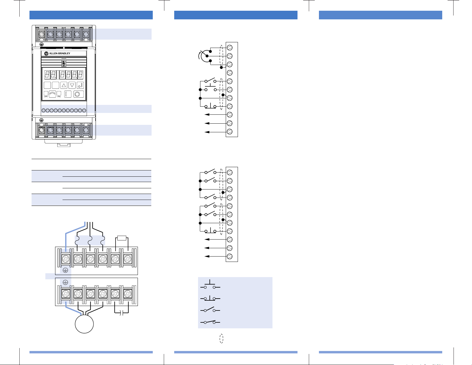
Control Wiring – TB3Power Wiring – TB1, TB2
Control WiringTB3
Motor & Capacitor
Module Wiring
TB2
Line Power & Dynamic
Brake Module Wiring
TB1
SELESC
DC+
W/T3
1
3
4 5 6 7 8 9 10 112
V/T2
U/T1
DC–
BR+
T/L3
S/L2
R/L1
BR–
Required Branch
Circuit Disconnect
➊
Dynamic Brake
Module (optional)
Capacitor Module
(optional)
Input Line
Protective Device
TB2
TB1
PE
BR+
T/L3
S/L2
R/L1
BR–
DC+
W/T3
V/T2
U/T1
DC–
Motor
Wire Size and Torque Ranges
➊ For single phase input applications, connect the AC input line to input terminals
S (L2) and T (L3).
10V DC Supply
Wiper
Common
4 – 20 mA Input
Reverse
Start
Common
Stop/Programmable
Normally Closed
Relay Common
Normally Open
SW1
SW2
Common
SW3
Run Reverse
Run Forward
Common
Stop/Programmable
Normally Closed
Relay Common
Normally Open
Three-Wire Control Shown
(Factory Default)
Two-Wire Control Shown
(Factory Default is Three-Wire)
1
23
4
567
89
10
11
1
23
4
567
89
10
11
N.O. Momentary Contact
N.C. Momentary Contact
N.O. Maintained Contact
N.C. Maintained Contact
Wires must be shielded.
Preset Speed Model
Analog Signal Follower Model
Model
4.0 kW (5 HP)
Three Phase
1.5 kW (2 HP)
Single Phase
All Other Ratings
Terminal
TB1, TB2
TB3
TB1, TB2
TB3
TB1, TB2
TB3
Min./Max. Wire Size
mm2 (AWG)
5.26-3.31 (10-12)
2.50-0.50 (14-22)
5.26-3.31 (10-12)
2.50-0.50 (14-22)
3.31-0.82 (12-18)
2.50-0.50 (14-22)
Min./Max. Torque
Nm (lb.-in.)
1.35-0.90 (12-8)
0.80-0.40 (8-4)
1.35-0.90 (12-8)
0.80-0.40 (8-4)
1.35-0.90 (12-8)
0.80-0.40 (8-4)
Troubleshooting
Page 2
Fault Codes
Fault
No. Fault Indication and Corrective Action
03 Power Loss Fault
Monitor incoming AC line for low voltage or line power
interruption.
04 ➊ UnderVoltage Fault
Monitor incoming AC line for low voltage or line power
interruption.
05 ➊ OverVoltage Fault
Bus overvoltage caused by motor regeneration. Monitor
incoming AC line for excessive voltage. Extend the decel
time or install dynamic brake module or external capacitor module.
06 ➊ Motor Stall Fault
Longer acceleration time or a reduced load required.
07 ➊ Motor Overload Fault
Reduce motor load until drive output current does not
exceed the current set by P42 - [Motor Overload
Current]. Reduce P38 - [Boost Select].
08 ➊ Over Temperature Fault
Clear blocked or dirty heat sink fins. Check ambient temperature. Check for blocked or non-operating fan.
11 Operator Error
Clear fault. Do not remove keypad under power.
12 ➊ Overcurrent FauIt
Check short circuit at the drive output or excessive load
conditions at the motor.
13 ➊ Software Overcurrent Fault
A longer acceleration time, reduced load, or removal of
motor shaft blockage is required.
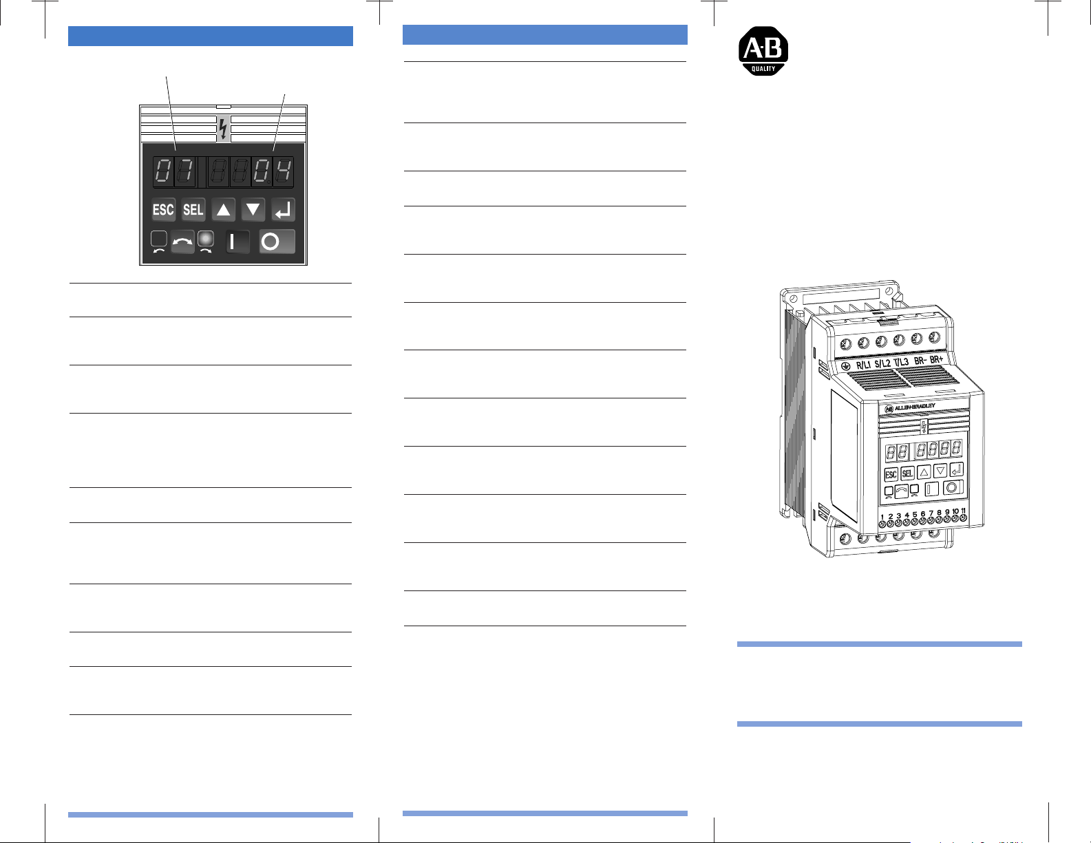
Parameter 07 - [Active Fault]
Fault Number
IMPORTANT: This publication is designed as a reference
tool. The 160 SSC User Manual (publication 0160-5.15) must
be consulted for more detailed information about parameters,
faults and hazards of personal injury.
160 SSC™ Variable
Speed Drive
Quick Reference
Series C, FRN 7.xx
Publication 0160-5.16 – June, 2000 P/N 189339 (02)
Supersedes October, 1998
20 ➊ Drive Overload Fault
Clear blocked or dirty heat sink fins. Check ambient temperature. Check for blocked or non-operating fan.
Reduce motor load current.
32 EEPROM Fault
Reset EEPROM using P56 - [Reset Functions]. Set to 1.
Cycle Power
33 Max Retries Fault
Repair system fault.
36 Incompatible Fault
Check the wiring between the drive and the motor.
Check the motor for a grounded phase.
38 Phase U Fault
Check the wiring between the drive and motor. Check
motor for grounded phase.
39 Phase V Fault
Check the wiring between the drive and motor. Check
motor for grounded phase.
40 Phase W Fault
Check the wiring between the drive and motor. Check
motor for grounded phase.
41 UV Short Fault
Check the motor and external wiring to the drive output
terminals for a shorted condition.
42 UW Short Fault
Check the motor and external wiring to the drive output
terminals for a shorted condition.
43 VW Short Fault
Check the motor and external wiring to the drive output
terminals for a shorted condition.
46 Intermittent Power Output Fault
Check the wiring between the drive and motor. Check
the motor for more than one shorted output.
48 Reprogram Fault
Clear fault.
➊ These faults have an auto reset feature. This feature automatically clears overvolt-
age, undervoltage and overtemperature faults 1 second after the fault condition is
removed. Refer to P51 - [Restart Time].
Page 3

Programming Steps
1. To program the value of a Program
Group parameter, enter the Program
Group by pressing the ESCape key.
The Program Mode Indicator will
illuminate.
2. Press the Up/Down Arrow keys until
the desired parameter number is
displayed.
3. Press the SELect key. The Program
Mode Indicator flashes, indicating that
you can use the Up/Down Arrow keys
to change the parameter value.
4. Press the arrow keys until the desired
value is shown.
Important: Continuously holding the
Up or Down key will cause the value
to increase or decrease as long as the
key is pressed.
5. When the desired value is displayed,
press the Enter key. This writes the
new value to memory. The Program
Mode Indicator will stop flashing and
the display will flash once indicating
that the new value has been accepted.
Important: If at any time (while in
the Program mode) you wish to abort
the editing process, press the ESCape
key. The original value of the
parameter will remain unchanged and
you will be exited from the Program
mode.
Action Description
Keypad Module Description
Enter
Pressing this key causes the current value
displayed to be entered into memory (only
while in the Program mode). When you press
this key the Program Mode Indicator remains
on, but stops flashing.
Escape
The ESCape key allows you to toggle
between the Display and Program modes.
When the Program mode is active, this key
will disable the editing of a parameter value.
Select
The SELect key enables editing of a
parameter value when the Program mode is
active. When you press this key the Program
Mode Indicator flashes.
Up/Down Arrow Keys
Use the Up/Down Arrow keys to scroll
through a list of parameters, or increase
and decrease parameter values. Press and
hold either key to increase scrolling
speed.
Real time frequency adjustment can be
achieved when using P58 - [Internal
Frequency]. Refer to the User Manual
for further information.
Start
This function is only active when
P46 - [Input Mode] is set to 2. When active,
pressing this key initiates a start command.
Stop
Pressing the Stop key will cause the motor to
stop, using the selected stop mode. Refer to
the P34 - [Stop Mode] parameter.
If the drive has stopped due to a fault,
pressing this key will clear the fault.
Reverse (Change Direction)
This function is only active when
P46 - [Input Mode] is set to 2. When active,
pressing this key causes the motor to ramp
down to 0 Hz and then ramp up to its set
speed in the opposite direction. When the
motor is running, pressing this key causes the
(currently illuminated) LED to flash, indicating motor rotation while decelerating to zero.
The other LED will illuminate indicating the
commanded direction.
Direction LEDs (Indicators)
The appropriate LED will illuminate continuously to indicate the commanded direction of
rotation. If the second LED is flashing, the
drive has been commanded to change
direction, but is still decelerating
.
Important: Actual motor rotation could be
different if motor leads are not connected
properly. See Chapter 4 of the User Manual
for details on verifying correct rotation.
Parameter Number Display
These two digits display the active parameter number for
both Display and Program Group parameters.
Program Mode Indicator
When the Program Mode Indicator flashes, you can edit the
parameter value. When the Display Mode is active, the
indicator will not be lit.
Parameter Value/Fault Number
These four digits display the parameter value or fault code
number.
Page 4

Program Group Parameters
No. Parameter Name Min/Max Range Units/Settings Default
30 [Accel Time 1] 0.0-600 0.1 Sec 10.0
31 [Decel Time 1]
➎
0.1-600 0.1 Sec 10.0
32 [Min. Freq.] 0-240 1 Hz 0
33 [Max. Freq.] 0-240 1 Hz 60
34 [Stop Mode Select] 0-3 0 = Ramp 0
1 = Coast
2 = DC Brake
3 = DC Brake Auto-Off
35 [Base Freq.] 10-240 1 Hz 60
36 [Base Voltage] 20-230/460 1 Volt 230/460
37 [Max. Voltage] 20-255/510 1 Volt 230/460
38 [Boost Select] 0-12 Start Volts (%) Midpoint (%) 2
0 = 0 9 = 45.0
1 = 2.5 10 = 40.0
2 = 5.0 11 = 35.0
3 = 7.5 12 = 30.0
4 = 10.0
5 = 12.5
6 = 15.0
7 = 17.5
8 = 20.0
39 [Skip Freq.] 0-240 1 Hz 240
40 [Skip Freq. Band] 0-30 1 Hz 0
41 [Motor Overload Select] 0-2 0 = No Derating 0
1 = Min. Derating
2 = Max. Derating
42 [Motor Overload Current] 0.1-200% of 0.01 Amps 115% of
Drive Rating Rating
43 [Current Limit] 1-180% of 1% 150%
Drive rating
44 [DC Hold Time] 0-25 0.1 Sec 0
45 [DC Hold Voltage] 0-115 1 Volt 0
46 [Input Mode]
➏
0-9 0 = 3-wire control 0
1 = 2-wire control
2 = Keypad control
3 = Momentary FWD/REV control
4 = 2-wire “Accel/Decel” control
5 = 2-wire Coast to Rest control
6 = 2-wire TB3/Keypad-Comm control
7 = 2-wire P59-[Frequency Select] control
8 = 2-wire Preset Speed control
9 = 2-wire PI control
47 [Output Configure] 0-10 0 = Drive Ready/Faulted 0
1 = At Frequency
2 = Motor Running
3 = Reverse
4 = Motor Overload
5 = Ramp Regulated
6 = Above Frequency
7 = Above Current
8 = Above DC Bus Voltage
9 = Retries Exhausted
10 = Above Power Factor Angle
48 [Output Threshold] 0-815 P47 - 6 = 0-240 Hz Range 0
P47 - 7 = 0-180% Range
P47 - 8 = 0-815 V Range
P47 - 10 = 0-180°
49 [PWM Freq.] 2.0-8.0 0.1 kHz 4.0
50 [Restart Tries] 0-9 Numeric Value 0
51 [Restart Time] 0.5-300 0.1 Sec 10.0
52 [DB Enable] 0-100 0 = Disable, > 0 = % of dB 0
53 [S-Curve] 0-10 0, 1...10 @ 10% Increments 0
54 [Clear Fault] 0-1 1 = Reset fault 0
55 [Memory Probe Address] Numeric Value Numeric Value Numeric
56 [Reset Functions] 0-2 0 = Idle State 0
1 = Reset Defaults
2 = Update Input Mode
Display Group Parameter List
Program Group Parameters
(continued)
No. Parameter Name Min/Max Range Units/Settings Default
57 [Program Lock] 0-1 0 = Unlock 0
1 = Lock
58 [Internal Freq.] 0-240 0.1 Hz 60
59 [Freq. Select] 0-1 0 = TB3 0
1 = Internal Freq.
60 [Zero Offset] ➌ –50.0 to +50.0 0.1% 0
61-68 [Preset Freq.0 – 7]➋0-240 0.1 Hz See Below
69 [Accel Time 2] 0.0-600 0.1 Sec. 20.0
70 [Decel Time 2]
➎
0.1-600 0.1 Sec. 20.0
71 [IR Compensation] 0-150 1% 50%
72 [Slip Compensation] 0.0-5.0 0.1 Hz 2.0 Hz
73 [Reverse Disable] 0-1 0 = Enable 0
1 = Disable
74 [Analog Select] ➌ 0-1 0 = Unipolar 0
1 = Bipolar
75 [Analog Input Min.] ➌ 0.0-150.0 0.1% 0.0%
76 [Analog Input Max.] ➌ 0.0-150.0 0.1% 100%
78 [Compensation] 0-2 Numeric Value 0
79 [Software Current Trip] 0-50% 1% 0
80 [Stall Fault Time] 0-5 0 = Normal (Appx. 60 sec) 0
1 = 2 x Normal
2 = 4 x Normal
3 = 6 x Normal
4 = 8 x Normal
5 = Disable
81 [PI Proportional Gain] ➌ 0-10.00 Numeric Value 0.01
82 [PI Integral Gain] ➌ 0-10.00 Numeric Value 0.01
83 [PI Process Reference] ➌0-100.0% 0.1% 0.0%
84 [PI Dead Band] ➌ 0-10.0% 0.1% 0.0%
➊ Status of Bit 3 for P46 - [Input Mode] setting 8 (TB3-2) is 0 = Open, 1 = Closed.
➋ Parameters 63, 64, 67 & 68 apply to the Preset Speed model only.
➌ This parameter setting applies to the Analog Signal Follower model only.
➍ When using P46 - [Input Mode] setting 4, the Accel and Decel times are selected
by providing an input to TB3-8.
➎ In firmware 7.05, there are minimum decel settings based on horsepower. 1 HP
and less remain 0.1 seconds, 2 HP is 0.2 seconds, 3 HP is 0.6 seconds, and 5 HP
is 0.7 seconds.
➏ In firmware 7.06, all Input Modes of parameter 46 allow PI control except Input
Mode 8.
Program Group Parameter List
Display Group Parameters
No. Parameter Name Min/Max Range Units/Settings
01 [Output Frequency] 0-240 Hz 0.1 Hz
02 [Output Voltage] 0-Max Voltage 1 Volt
03 [Output Current] 0-2 x Rtd. Out. Curr. 0.01Amps
04 [Output Power] 0-2 x Rtd. Out. Power 0.01 kW
05 [Bus Voltage] 0-400 (230V) 1 Volt
0-800 (460V)
06 [Frequency Command] 0-240 0.1 Hz
07 [Active Fault] 0-48 Numeric Value
08 [Heatsink Temperature] 69-150 1 Degree C
09 [Controller Status] 0000 to 1011 Bit 3 Bit 2 Bit 1 Bit 0
Decel Accel Forward Running
10 [Controller Type] Numeric Value Numeric Value
11 [Control Version] Fixed Value Numeric Value
12 [Input Status]
➏
0000 to 1111 See Below
13 [Power Factor Angle] 0.0-180.0 0.1 Degrees
14 [Memory Probe Display] Numeric Value Numeric Value
15 [Preset Status] 0000 to 0111 Bit 3 Bit 2 Bit 1 Bit 0
Not Used SW3➋SW2 SW1
16 [Analog Input] ➌ –150 to +150 0.1%
17 [Fault Buffer 0] 0-48 Numeric Value
18 [Fault Buffer 1] 0-48 Numeric Value
19 [Fault Buffer 2] 0-48 Numeric Value
1
P46
Input
Description
Mode
3-Wire
0
2-Wire
1
Keypad
2
Mom. Run Fwd/Rev
3
Accel/Decel
4
Coast to Rest
5
TB3/Keypad or Comm.
6
Frequency Select
7
SF1 Preset Speed
8
2-Wire PI Control
9
4
2 3
Bit 3
0 = Positive
Analog Input
1 = Negative
Analog Input
➊
567
Bit 1Bit 2Bit 0
TB3-6
TB3-8
Bit 2
Bit 1
Start
Stop
Run Forward
Stop
N/A
Stop
Run Forward
Stop
Run Forward
0=Accel 2/Decel 2
1=Accel1/Decel 1
Run Forward
Coast to Rest Stop
Run Forward
0=TB3 Control
1=Keypad or Comm.
Run Forward
0=Analog Freq. Select
1=Internal Freq. Select
Run Forward
0=Open
1=Closed
Run Forward
0=PI
1=Internal Freq. Select
9
8
10
11
TB3-5
Bit 0
Reverse
Run Reverse
N/A
Run Reverse
Run Reverse
Run Reverse
Run Reverse
Run Reverse
Run Reverse
Run Reverse
TB3
No.
61
62
63
64
65
66
67
68
1
Name
[Preset 0]
[Preset 1]
[Preset 2]
[Preset 3]
[Preset 4]
[Preset 5]
[Preset 6]
[Preset 7]
4
32
567
SW3SW2SW1 (Preset Speed Model Designations Shown)
Preset Speed
Model
TB3-2
Default
3 Hz
20 Hz
30 Hz
40 Hz
45 Hz
50 Hz
55 Hz
60 Hz
TB3-4
(SW3)
TB3-1
(SW2)
(SW1)
0
0
0
0
1
0
1
0
0
1
0
1
1
1
1
1
Signal Follower
Model
TB3-8
(SW2)
0
0
1
0
0
N/A
1
N/A
0
1
1
1
0
N/A
1
N/A
89
TB3-2
Accel
(SW1)
0
Parameter 30,
1
[Accel Time 1]
N/A
N/A
0
Parameter 69,
1
[Accel Time 2]
N/A
N/A
10
➍
11
TB3
Decel
Parameter 31,
[Decel Time 1]
Parameter 70,
[Decel Time 2]
➍
 Loading...