

Page 1

User Manual
Bulletin 1608M MegaDySC Dynamic Voltage Sag Corrector
1608M—400 Amp Models
Page 2
Important User Information
IMPORTANT
Solid-state equipment has operational characteristics differing from those of electromechanical equipment. Safety Guidelines for the
Application, Installation and Maintenance of Solid State Controls (publication SGI-1.1
office or online at http://www.rockwellautomation.com/literature/
hard-wired electromechanical devices. Because of this difference, and also because of the wide variety of uses for solid-state equipment, all
persons responsible for applying this equipment must satisfy themselves that each intended application of this equipment is acceptable.
In no event will Rockwell Automation, Inc. be responsible or liable for indirect or consequential damages resulting from the use or application
of this equipment.
The examples and diagrams in this manual are included solely for illustrative purposes. Because of the many variables and requirements
associated with any particular installation, Rockwell Automation, Inc. cannot assume responsibility or liability for actual use based on the
examples and diagrams.
No patent liability is assumed by Rockwell Automation, Inc. with respect to use of information, circuits, equipment, or software described in
this manual.
Reproduction of the contents of this manual, in whole or in part, without written permission of Rockwell Automation, Inc., is prohibited.
Throughout this manual, when necessary, we use notes to make you aware of safety considerations.
) describes some important differences between solid-state equipment and
WARNING: Identifies information about practices or circumstances that can cause an explosion in a hazardous environment,
which may lead to personal injury or death, property damage, or economic loss.
available from your local Rockwell Automation sales
ATTENTION: Identifies information about practices or circumstances that can lead to personal injury or death, property
damage, or economic loss. Attentions help you identify a hazard, avoid a hazard, and recognize the consequence.
SHOCK HAZARD: Labels may be on or inside the equipment, for example, a drive or motor, to alert people that dangerous
voltage may be present.
BURN HAZARD: Labels may be on or inside the equipment, for example, a drive or motor, to alert people that surfaces may
reach dangerous temperatures.
Identifies information that is critical for successful application and understanding of the product.
MegaDySC, Allen-Bradley, Rockwell Software, Rockwell Automation, and TechConnect are trademarks of Rockwell Automation, Inc. Trademarks not belonging to Rockwell Automation are property of
their respecti ve companies.
Additional Resources
These documents contain additional information concerning related products from Rockwell Automation.
Resource Description
Industrial Automation Wiring and Grounding Guidelines,
publication 1770-4.1
Product Certifications website, http://www.ab.com
Provides general guidelines for installing a Rockwell
Automation industrial system.
Provides declarations of conformity, certificates, and
other certification details.
You can view or download publications at http:/www.rockwellautomation.com/literature/
. To order paper copies of
technical documentation, contact your local Allen-Bradley distributor or Rockwell Automation sales representative.
Page 3

Ch 1 - Introduction
Ch 2 - Installation
Ch 3 - Communications
Ch 4 - Applying Power
Ch 5 - Operation
Ch 6 - Display Screen
Table of Contents
Important User Information. . . . . . . . . . . . . . . . . . . . . . . . . . . . . . . . . . . . . . . . . . . . . . 2
Additional Resources. . . . . . . . . . . . . . . . . . . . . . . . . . . . . . . . . . . . . . . . . . . . . . . . . . . . . 2
Safety Considerations . . . . . . . . . . . . . . . . . . . . . . . . . . . . . . . . . . . . . . . . . . . . . . . . . . . . 5
System Components . . . . . . . . . . . . . . . . . . . . . . . . . . . . . . . . . . . . . . . . . . . . . . . . . . . . . 7
System Layout . . . . . . . . . . . . . . . . . . . . . . . . . . . . . . . . . . . . . . . . . . . . . . . . . . . . . . . . . . . 8
System Clearance . . . . . . . . . . . . . . . . . . . . . . . . . . . . . . . . . . . . . . . . . . . . . . . . . . . . . . . 10
System Mounting . . . . . . . . . . . . . . . . . . . . . . . . . . . . . . . . . . . . . . . . . . . . . . . . . . . . . . . 10
Electrical Interconnections . . . . . . . . . . . . . . . . . . . . . . . . . . . . . . . . . . . . . . . . . . . . . . 11
Instructions for energizing loads before commissioning . . . . . . . . . . . . . . . . 12
MegaDySC System Installation Connections Checklist . . . . . . . . . . . . . . . . 14
MegaDySC System Interconnections Checklist . . . . . . . . . . . . . . . . . . . . . . . 14
Remote Diagnostics and Remote Bypass . . . . . . . . . . . . . . . . . . . . . . . . . . . . . . . . . . 15
CBB Contacts (Bypass Circuit Breaker) . . . . . . . . . . . . . . . . . . . . . . . . . . . . . . . . . . 15
CBI Contacts (Input Circuit Breaker) . . . . . . . . . . . . . . . . . . . . . . . . . . . . . . . . . . . . 16
Remote Seamless Bypass Command-EPO. . . . . . . . . . . . . . . . . . . . . . . . . . . . . . . . . 16
Contact Ratings . . . . . . . . . . . . . . . . . . . . . . . . . . . . . . . . . . . . . . . . . . . . . . . . . . . . . . . . 16
MegaDySC Status Contacts . . . . . . . . . . . . . . . . . . . . . . . . . . . . . . . . . . . . . . . . . . . . . 17
RS-232 Serial communications. . . . . . . . . . . . . . . . . . . . . . . . . . . . . . . . . . . . . . . . . . . 17
i-Sense Voltage Monitor Communications. . . . . . . . . . . . . . . . . . . . . . . . . . . . . . . . 18
Applying Power . . . . . . . . . . . . . . . . . . . . . . . . . . . . . . . . . . . . . . . . . . . . . . . . . . . . . . . . 19
System Description . . . . . . . . . . . . . . . . . . . . . . . . . . . . . . . . . . . . . . . . . . . . . . . . . . . . . 21
MegaDySC Operation . . . . . . . . . . . . . . . . . . . . . . . . . . . . . . . . . . . . . . . . . . . . . . . . . . 21
Automatic Bypass Switchboard Operation . . . . . . . . . . . . . . . . . . . . . . . . . . . . . . . . 22
Automatic Bypass Switchboard Operating Instructions . . . . . . . . . . . . . . . . . . . . 23
Automatic System . . . . . . . . . . . . . . . . . . . . . . . . . . . . . . . . . . . . . . . . . . . . . . . . . . 23
Manual Transfer to Maintenance Bypass (Bypass Mode) . . . . . . . . . . . . . . . 23
Manual Transfer to MegaDySC (Normal Mode) . . . . . . . . . . . . . . . . . . . . . . 23
Transient Voltage Surge Suppression . . . . . . . . . . . . . . . . . . . . . . . . . . . . . . . . . . . . . 24
Troubleshooting Notes. . . . . . . . . . . . . . . . . . . . . . . . . . . . . . . . . . . . . . . . . . . . . . . . . . 24
Normal Mode . . . . . . . . . . . . . . . . . . . . . . . . . . . . . . . . . . . . . . . . . . . . . . . . . . . . . . 25
Diagnostic Indicators . . . . . . . . . . . . . . . . . . . . . . . . . . . . . . . . . . . . . . . . . . . . . . . 26
Overview. . . . . . . . . . . . . . . . . . . . . . . . . . . . . . . . . . . . . . . . . . . . . . . . . . . . . . . . . . . . . . . 27
Home Screen . . . . . . . . . . . . . . . . . . . . . . . . . . . . . . . . . . . . . . . . . . . . . . . . . . . . . . . . . . . 29
Mechanical Bypass . . . . . . . . . . . . . . . . . . . . . . . . . . . . . . . . . . . . . . . . . . . . . . . . . . 29
System Status. . . . . . . . . . . . . . . . . . . . . . . . . . . . . . . . . . . . . . . . . . . . . . . . . . . . . . . . . . . 30
Voltage Sag Events . . . . . . . . . . . . . . . . . . . . . . . . . . . . . . . . . . . . . . . . . . . . . . . . . . . . . . 31
Voltage Sag Log. . . . . . . . . . . . . . . . . . . . . . . . . . . . . . . . . . . . . . . . . . . . . . . . . . . . . 31
Voltage Sag Detail . . . . . . . . . . . . . . . . . . . . . . . . . . . . . . . . . . . . . . . . . . . . . . . . . . 32
Voltage Sag RMS Voltage Charts. . . . . . . . . . . . . . . . . . . . . . . . . . . . . . . . . . . . . 33
Voltage Sag Notification . . . . . . . . . . . . . . . . . . . . . . . . . . . . . . . . . . . . . . . . . . . . 33
System Events . . . . . . . . . . . . . . . . . . . . . . . . . . . . . . . . . . . . . . . . . . . . . . . . . . . . . . . . . . 34
System Event Log . . . . . . . . . . . . . . . . . . . . . . . . . . . . . . . . . . . . . . . . . . . . . . . . . . . 34
System Event Detail. . . . . . . . . . . . . . . . . . . . . . . . . . . . . . . . . . . . . . . . . . . . . . . . . 35
System Event Notification. . . . . . . . . . . . . . . . . . . . . . . . . . . . . . . . . . . . . . . . . . . 36
System Configuration . . . . . . . . . . . . . . . . . . . . . . . . . . . . . . . . . . . . . . . . . . . . . . . . . . . 37
Model Information . . . . . . . . . . . . . . . . . . . . . . . . . . . . . . . . . . . . . . . . . . . . . . . . . . . . . 37
Run System Tests . . . . . . . . . . . . . . . . . . . . . . . . . . . . . . . . . . . . . . . . . . . . . . . . . . . 38
Diagnostics Mode. . . . . . . . . . . . . . . . . . . . . . . . . . . . . . . . . . . . . . . . . . . . . . . . . . . 38
Rockwell Automation Publication 1608M-UM001A-EN-P - September 2013 3
Page 4

Table of Contents
Ch 7 - Maintenance
Ch 8 - Specifications
Preventative Maintenance . . . . . . . . . . . . . . . . . . . . . . . . . . . . . . . . . . . . . . . . . . . . . . . 39
Monthly Checks . . . . . . . . . . . . . . . . . . . . . . . . . . . . . . . . . . . . . . . . . . . . . . . . . . . . 39
3-6 Month Checks . . . . . . . . . . . . . . . . . . . . . . . . . . . . . . . . . . . . . . . . . . . . . . . . . . 39
Servicing . . . . . . . . . . . . . . . . . . . . . . . . . . . . . . . . . . . . . . . . . . . . . . . . . . . . . . . . . . . . . . . 42
Automatic Circuit Breakers, Safety Interlocks and Stored Energy . . . . . . . 42
Fuses . . . . . . . . . . . . . . . . . . . . . . . . . . . . . . . . . . . . . . . . . . . . . . . . . . . . . . . . . . . . . . . . . . . 42
Automatic Bypass Switchboard Fuses . . . . . . . . . . . . . . . . . . . . . . . . . . . . . . . . . 43
MegaDySC and ER Cabinet Fuses . . . . . . . . . . . . . . . . . . . . . . . . . . . . . . . . . . . . 43
Technical Specifications . . . . . . . . . . . . . . . . . . . . . . . . . . . . . . . . . . . . . . . . . . . . . . . . . 45
4 Rockwell Automation Publication 1608M-UM001A-EN-P - September 2013
Page 5
Chapter 1
Introduction
The Allen-Bradley Bulletin 1608M MegaDySC Dynamic Sag Corrector is
engineered to provide years of trouble-free voltage sag (dip) protection. The
patented DySC technology does not use batteries, requires only routine
maintenance, includes three-stage transient voltage surge suppression, and has
unparalleled energy efficiency. Most electronic devices found in industry today
are susceptible to power disturbances. A momentary sag in line voltage can reset
or damage sensitive production equipment. The MegaDySC provides
instantaneous dynamic sag correction to help your equipment ride through these
common events. The MegaDySC connects normal utility power directly to the
load until a voltage sag occurs. During a sag, the MegaDySC inverter is activatedadding missing voltage to keep the load voltage within the normal range. When
utility power returns to normal, the inverter is deactivated and the MegaDySC is
quickly ready to correct the next sag.
The MegaDySC reports these voltage sag events through its integrated touch
screen display and provides system status, voltage sag notification and history,
runtime statistics and system history in a simple and intuitive touch-based user
interface.
Safety Considerations
The MegaDySC is designed to operate in industrial applications. Follow these
guidelines to ensure that the safety and installation of the MegaDySC are
handled with appropriate care.
SHOCK HAZARD: The MegaDySC has high voltage remaining up to 5 minutes
after disconnection from the AC line. Touching exposed or disconnected
terminals, cables or parts of the MegaDySC can lead to serious injuries or even
death. Wait for a minimum of 5 minutes before performing any service or
testing on the MegaDySC after power is removed. High voltage remains if red
LED indicators above capacitor banks are lighted. Keep the cabinet doors closed
and locked to ensure proper cooling airflow and to protect personnel from
dangerous voltages inside the MegaDySC.
ATTENTION: - To reduce the risk of fire or electric shock, install this MegaDySC
in a temperature and humidity controlled, indoor environment, free of
conductive contaminants.
• Avoid installing the MegaDySC directly near heat-emitting equipment such as ovens, heaters, or
furnaces.
• Ambient temperature must not exceed 40°C (104°F).
• Do not operate near water or excessive humidity (95% max).
• When punching or drilling holes for conduit fittings, take care to avoid dropping metallic particles
inside the enclosure as this can result in electrical damage.
• The system is not intended for outdoor use.
• The operating environment should be maintained within the parameters stated in this manual.
• Only authorized service personnel should perform ser vice on the MegaDySC.
• Ensure all power is disconnected before performing installation or service.
Rockwell Automation Publication 1608M-UM001A-EN-P - September 2013 5
Page 6

Chapter 1
ATT EN TI ON : Internal components can be easily damaged by electrostatic
discharge (ESD). Do not touch circuit boards or electronic components with
hands or metal objects. The MegaDySC is not rated to directly power life
support equipment.
• Ensure the area around the MegaDySC is clean and uncluttered.
• Observe all DANGER, CAUTION, and WARNING notices affixed to the inside and outside of the
equipment.
6 Rockwell Automation Publication 1608M-UM001A-EN-P - September 2013
Page 7
Installation
Chapter 2
System Components
The MegaDySC system consists of two enclosures including one “DySC 400 A
Module” MegaDySC section and one Automatic Bypass Switchboard, which are
shipped separately and must be mechanically and electrically interconnected at
the time of installation. The MegaDySC section houses the static bypass and
voltage sag-correction electronics as well as the optional extended-run (ER)
module. The Automatic Bypass Switchboard houses the maintenance bypass
circuit breaker (CBB), the MegaDySC input (CBI) and output (CBO) circuit
breakers, automatic controls, and the i-Sense® voltage-monitoring sensor.
This document applies to the following MegaDySC System Models:
Table 1 - MegaDySC System Models
Catalog Number Current Rating Voltage
Rating
1608M-400A380V3S 400A 380V 3 SR
1608M-400A380V3E 400A 380V 3 ER
1608M-400A380V4S 400A 380V 4 SR
1608M-400A380V4E 400A 380V 4 ER
1608M-400A400V3S 400A 400V 3 SR
1608M-400A400V3E 400A 400V 3 ER
1608M-400A400V4S 400A 400V 4 SR
1608M-400A400V4E 400A 400V 4 ER
1608M-400A415V3S 400A 415V 3 SR
1608M-400A415V3E 400A 415V 3 ER
1608M-400A415V4S 400A 415V 4 SR
1608M-400A415V4E 400A 415V 4 ER
1608M-400A460V3S 400A 460V 3 SR
1608M-400A460V3E 400A 460V 3 ER
1608M-400A460V4S 400A 460V 4 SR
1608M-400A460V4E 400A 460V 4 ER
1608M-400A480V3S 400A 480V 3 SR
1608M-400A480V3E 400A 480V 3 ER
1608M-400A480V4S 400A 480V 4 SR
1608M-400A480V4E 400A 480V 4 ER
3 /
4-wire
SR / ER
Rockwell Automation Publication 1608M-UM001A-EN-P - September 2013 7
Page 8
Chapter 2 Installation
System Layout
Figure 1 - Standard Run (SR) System Layout
8 Rockwell Automation Publication 1608M-UM001A-EN-P - September 2013
Page 9
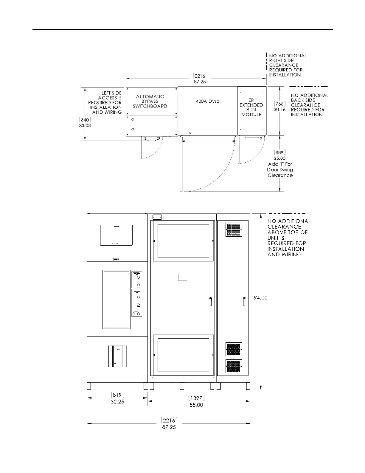
Figure 2 - Extended Run (ER) System Layout
Installation Chapter 2
Rockwell Automation Publication 1608M-UM001A-EN-P - September 2013 9
Page 10
Chapter 2 Installation
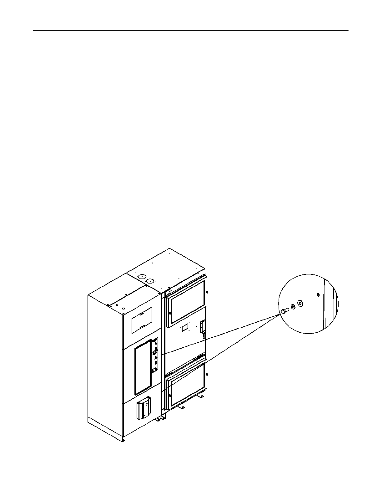
Attach the MegaDySC section to the Automatic Bypass
switchboard using the six (6) sets of 3/8” hardware supplied.
• Install three (3) sets along the front door frame and three
(3) sets along the rear frame. Hardware along the rear
frame may be omitted if rear access to the switchboard is
not available: it is necessary to remove the rear panel of the
switchboard to install the rear sets of hardware.
• Install bolts from the switchboard side and thread into the
weld nuts located in the MegaDySC section enclosure.
• Each set consists of one 3/8-16 x 1.0” bolt, one 3/8 split lock
washer and one 3/8” flat washer, assembled as shown.
System Clearance
System Mounting
The MegaDySC doors are hinged on the left, and clearance must be given to
allow the door to swing open 90 degrees to the front of the enclosure.
Clearance for the Automatic Bypass switchboard must allow the front panels to
swing (left side hinged) open 90 degrees to the front of its enclosure.
Either rear (preferred) or left side access to the Automatic Bypass switchboard
will be required during installation wiring and cabinet interconnect wiring.
The MegaDySC system is floor-mounted, and should be secured using the 0.63”
diameter mounting holes provided along the bottom channels. The MegaDySC
section is provided with all necessary interconnect wiring to the Automatic
Bypass switchboard section. Proper line-up is critical: The MegaDySC section
must be located to the right of the Automatic Bypass section when viewed from
the front of the system.
The "DySC 400A Module" MegaDySC section is shipped separately from the
Automatic Bypass switchboard. The MegaDySC section must be secured to the
Automatic Bypass enclosure with the 3/8” hardware supplied. See Figure 3
for
fastening locations and hardware arrangement. The optional ER enclosure is
permanently connected to the MegaDySC section prior to shipment.
Figure 3 - System Mounting
10 Rockwell Automation Publication 1608M-UM001A-EN-P - September 2013
Page 11
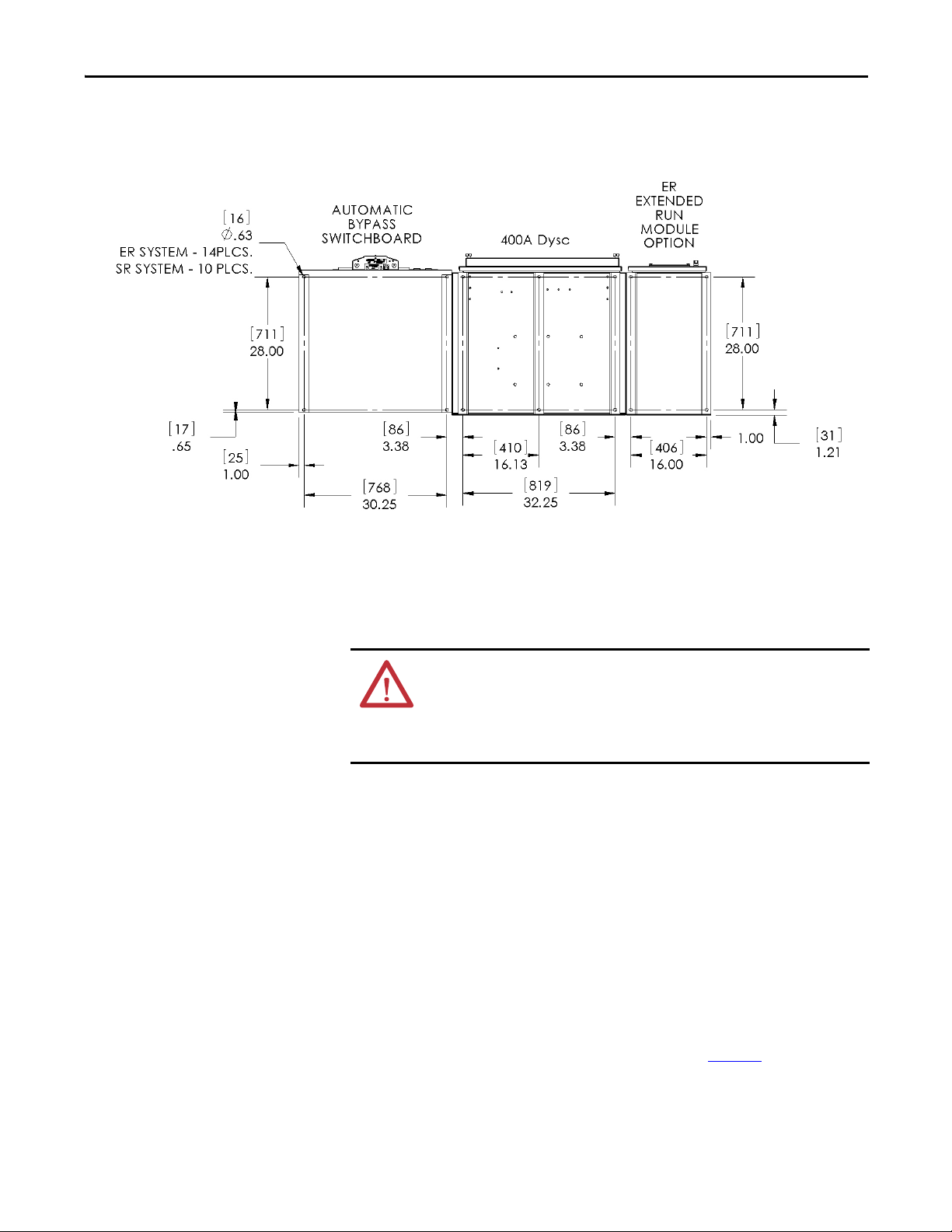
Figure 4 - Floor Mounting Detail
Installation Chapter 2
Electrical Interconnections
WARNING: Equipment must be earth-grounded according to local and
national electrical codes. Failure to supply proper equipment grounding may
result in electrical shock or death. All interconnection wiring will be
installed by a factory-trained technician during system
commissioning.
The MegaDySC cabinet and the Automatic Bypass (ABP) Switchboard are
shipped separately. The customer is responsible for system mounting. All
interconnecting power cables are provided (shipped inside the ABP switchboard)
and will be connected by a factory-trained technician during commissioning. At
installation the loose ends of the main cables will be routed through the bushings
in the side of the ABP switchboard and connected inside the MegaDySC cabinet
to the appropriately labeled terminals. A control wiring harness is also provided
in the ABP and must be connected to the MegaDySC cabinet. This cable harness
is routed through two large holes, one in the ABP cabinet and one in the
MegaDySC cabinet, located at the bottom front of the cabinets. The harness is
plugged into the associated terminal block located in the lower, left corner of the
MegaDySC cabinet. Finally, the incoming electrical service and outgoing load
cables are brought in through the top (or bottom) of the ABP switchboard and
connected to the appropriate bus locations, as shown in Figure 6
connected to the bus bar terminals labeled L1, L2, L3 and the protected load is
connected to the bus bar terminals labeled X1, X2, X3.
. AC input is
Rockwell Automation Publication 1608M-UM001A-EN-P - September 2013 11
Page 12
Chapter 2 Installation
Instructions for energizing loads before commissioning
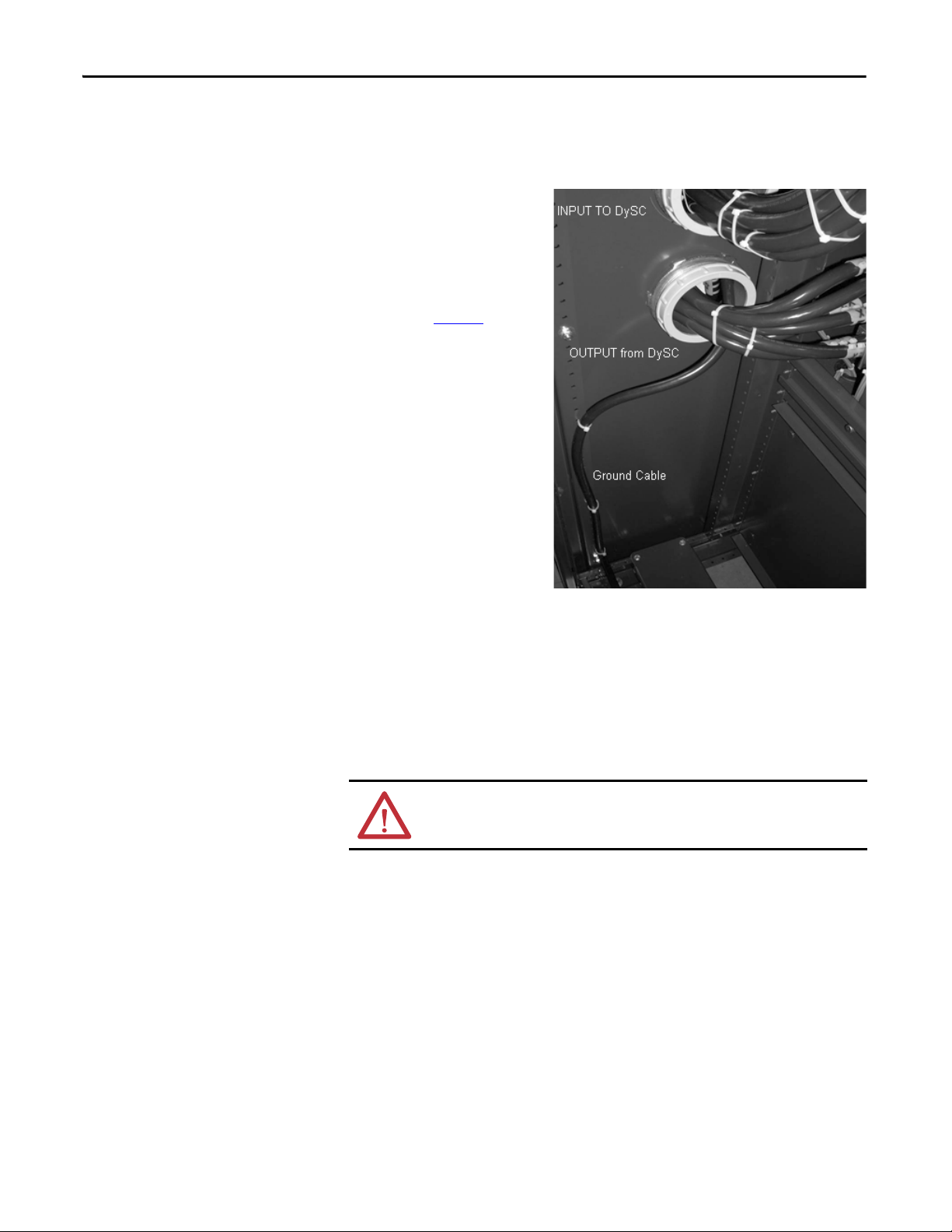
Figure 5 - Rear view of Automatic Bypass Switch board
If the MegaDySC system must
be installed and put into
maintenance bypass mode
before commissioning, the
installers should put the
system enclosures in place as
described on page 10
feed the loose ends of intercabinet cables from the
switchboard into the
MegaDySC cabinet:
1. Route the INPUT power cables (labeled L1, L2, L3) through the top bushing in the right-side wall of the switchboard, labeled “Input to DySC”
, then
2. Route the OUTPUT power cables (X1, X2, X3) and Ground cable through the bottom bushing labeled “Output from DySC”
3. Route the control cable harness from the lower front switchboard pan into
the MegaDySC section through the matching holes in the lower front side
panels. Install the 3.5” snap-in grommet so that it protrudes into the
MegaDySC cabinet before routing the harness. Plug the harness header
into connector TB5 on the MegaDySC floor.
WARNING: 120VAC is present at several pins of the harness header when the
switchboard is energized.
4. Lockout circuit breakers CBI and CBO in the Automatic Bypass Switchboard.
5. Install utility input and load output conductors.
6. Energize the switchboard.
The MegaDySC touch screen display will be active only if the control
harness has been plugged in on the MegaDySC side. If the screen is active
then 120VAC is present at several points within the MegaDySC enclosure.
7. Push the green CLOSE CBB button to energize loads. The remaining interconnections and commissioning must be completed by factory-trained technicians.
12 Rockwell Automation Publication 1608M-UM001A-EN-P - September 2013
Page 13
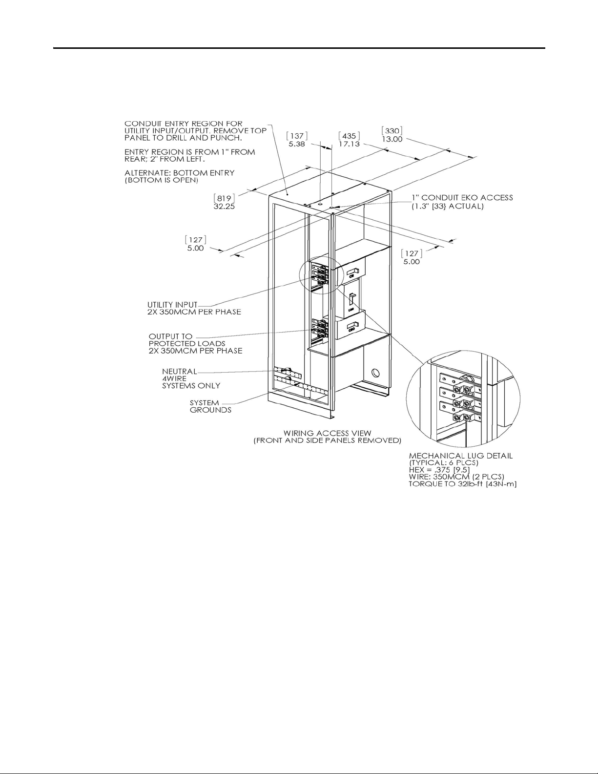
Figure 6 - Switchboard Terminations and Conduit landing areas
Installation Chapter 2
Rockwell Automation Publication 1608M-UM001A-EN-P - September 2013 13
Page 14

Chapter 2
MegaDySC System Installation Connections Checklist
• Connect the Automatic Bypass Switchboard ground bus to an earth
ground in accordance with the National Electrical Code and local codes.
• Connect the AC input (line) conductors to the terminals labeled "L1",
"L2" and "L3". The set is labeled "UTILITY INPUT". These terminals are
located left of the switchboard. See Figure 6
• Connect the AC output (load) conductors to the terminals labeled "X1",
"X2" and "X3". The set is labeled "OUTPUT TO PROTECTED
LOADS". See Figure 6
• For 4-wire models only: connect input and output Neutral (N)
conductors to the NEUTRAL bus bar. The input N connection is
required for proper operation of 4-wire models. Do not connect to the
NEUTRAL bus bar in 3-wire models.
• Check all electrical terminations for properly torqued connections.
See Figure 6
• For i-Sense communications: connect either an analog telephone line to
RJ11 jack or Ethernet cable to RJ45 jack. The RJ11 and RJ45 jacks are
located in the upper switchboard compartment. They can be accessed
through a 1" conduit knockout in the top of the cabinet. See Figure 6
Refer to i-Sense Voltage Monitor Communications
.
.
.
on page 18.
and
MegaDySC System Interconnections Checklist
(To be completed by factory-trained technician)
• Connect the Automatic Bypass (ABP) Switchboard-to-MegaDySC
ground cable to the ground bus in the MegaDySC.
• Connect line side cables from input circuit breaker (CBI) located in the
ABP Switchboard to the MegaDySC section bus bars labeled RH1-L1,
RH1-L2 and RH1-L3 respectively.
• Connect load side cables from the output circuit breaker (CBO) located in
the ABP Switchboard to the MegaDySC section bus bars labeled RH1X1, RH1-X2 and RH1-X3 respectively.
• Plug the control cable from the ABP Switchboard into the MegaDySC
cabinet.
14 Rockwell Automation Publication 1608M-UM001A-EN-P - September 2013
Page 15
Communications
K1
5
1362
4
78
CBB
N/C
CBB1
N/O
TB1
terminal block
NC
1
A
C
2
A
NO
3
A
NC
1B
C
2B
NO
3B
NC
4
A
C
5
A
NO
6
A
NC
4B
C
5B
NO
6B
.
7B
.
8B
.
9B
NC
10B
C
11B
NO
12B
unused
7
A
unused
8
A
unused
9
A
NC
10A
C
11A
NO
12A
NC
13B
C
14B
NO
15B
NC
13A
C
14A
NO
15A
Customer-Supplied Contact:
Close to command
Seamless Bypass
Chapter 3
Remote Diagnostics and Remote Bypass
Relay dry contacts are available for remote monitoring of the state of the Bypass
Circuit Breaker CBB and the Input Circuit Breaker CBI shunt-trip condition
(See Figure 7
). In addition, a customer-supplied relay may be used to remotely
command a Seamless Bypass operation, as described in Automatic Bypass
Switchboard Operation on page 22. These functions are available from terminal
block TB1 located in the upper compartment of the bypass switchboard. See
Figure 9
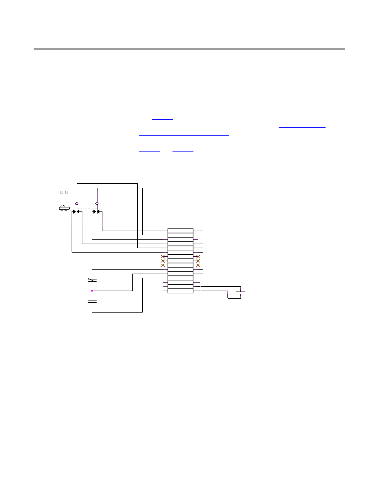
Figure 7 - Schematic Diagram - Status Relay Contacts
and Figure 6 for recommended conduit entry location.
CBB Contacts (Bypass Circuit Breaker)
"Normal" position for the Bypass Breaker is defined as the breaker being OFF, or
Open. As such, the Normally-Open contacts are open when the Breaker is open;
the Normally-Closed contacts will open when the breaker is closed.
Example: Normal run: CBB will be Open; therefore TB1/11B will be electrically
connected to TB1/10B.
Rockwell Automation Publication 1608M-UM001A-EN-P - September 2013 15
Page 16

Chapter 3 Communications
CBI Contacts (Input Circuit Breaker)
Remote Seamless Bypass Command-EPO
Relay K1 activates on any input circuit breaker shunt-trip signal ("CBI-ST").
Heatsink over-temperature, cabinet over-temperature, SCR Failure, Blown-Fuse
or Open-Door indicators will all assert the CBI ST signal to open the input
circuit breaker, removing power from the MegaDySC. When this signal is
present, Relay K1 is activated and its Normally-Open contacts close. Note that
this is not a position indicator for the CBI circuit breaker: the CBI ST signal will
be present for only one (1) second when the shunt-trip command is asserted. The
Input breaker CBI will not automatically reclose after any shunt trip operation;
user intervention is required to manually reset the system to operational status.
A normally-open PLC contact, relay contact, or push-button contact may be
connected between TB1/14 and TB1/15. Contacts must be rated for at least
120V AC at 25 mA. Note that 120V AC is present at TB1/15 when the
switchboard is energized. Close the contact to initiate an automatic seamless
bypass operation: CBB will close, then CBI and CBO will open, removing power
from the MegaDySC cabinet; voltage sag correction will then be disabled.
This feature may be utilized as an Emergency Power Off (EPO) function for the
MegaDySC cabinet. Power to the output loads or output distribution panel, if
present, will not be interrupted. Note that the automatic bypass functionality
requires that nominal AC power is present at the switchboard input terminals.
Contact Ratings
The CBB aux. contacts (Terminals 10B-12B of TB1) are rated at 6A @
600VAC, 0.5A @ 125VDC or 0.25A @ 250VDC. The DC ratings are for noninductive loads only. The K1 contacts (Terminals 1B - 6B of TB1) are rated at
10A @ 110VAC Resistive, 7.5A @ 110VAC Inductive, 10A @ 24V DC resistive
and 5A @ 24V DC inductive.
WARNING: Remove power from the DySC system prior to connecting any alarm
notification device. Access to the terminal contacts risks exposure to a potential
arc flash and/or electrocution hazard unless power to the switchboard is
removed.
16 Rockwell Automation Publication 1608M-UM001A-EN-P - September 2013
Page 17

Communications Chapter 3
MegaDySC Status Contacts
RS-232 Serial communications
Three relay contacts indicate MegaDySC electronics status; refer to Figure 8.
The contacts are form A and close upon occurrence of the named event: (a) any
SAG EVENT, when rms input voltage drops below 88.5% of rated value; (b)
OUTPUT OK, when output voltage remains between 87% and 110%; and (c) a
system ALARM event. These relay contact are rated 24V at 1A.
For access, remove the small metal cover above the door of the MegaDySC
section
• All wiring is to be Class 2, limited to 24 Volts, AC or DC.
• Acceptable wire gauges range from 24AWG to 12AWG (0.205-2.5mm2).
• Tighten connections to 5.0 lb-in (0.6 N-m). A plug-in connector is
provided to facilitate wiring.
• For permanent installation of communications conductors, a standard
conduit knockout is located on the cabinet top.A removable connector
(plug) is provided to facilitate wiring. All wiring is to be class 2, limited to
24 Volts, AC or DC. Acceptable wire gauges range from 24AWG to
12AWG (0.205 - 2.5 mm2). Torque connections to 5lb-in (0.6 N-m)
A DE-9 male connector is provided for remote communications. Contact
Rockwell Automation Technical Support for protocol details.
Figure 8 - Serial Communications Port and MegaDySC Status Relay Contacts
Rockwell Automation Publication 1608M-UM001A-EN-P - September 2013 17
Page 18

Chapter 3 Communications
Conduit
Entry for
optional TB1
i-Sense
communications
jacks (access from
above)
Conduit Entry for
i-Sense
communications
TB1
i-Sense Voltage Monitor Communications
The i-Sense voltage monitor is located on the bottom front of the bypass
switchboard and is pre-wired to monitor the MegaDySC input and output
voltages. The i-Sense Ethernet and Modem communications ports are internally
connected to the RJ45 and RJ11 jacks, respectively, located in the upper
compartment of the bypass switchboard. See Figure 6
and Figure 9 for conduit
entry locations. A communications connection is required to enable i-Sense
monitoring. See publication 1608S-UM001A-EN-P for more information.
Figure 9 - Communications Conduit Entrance view from within upper switchboard compartment
18 Rockwell Automation Publication 1608M-UM001A-EN-P - September 2013
Page 19

Chapter 4
Applying Power
ATT EN TI ON : The MegaDySC system must be commissioned by factory-trained
engineers. Do not energize the MegaDySC until instructed to do so by
commissioning engineers. If the Automatic Bypass switchboard must be
installed and energized before commissioning, follow instructions next to
Figure 5
.
• After installation make certain there are no metal filings or any conductive
debris in or on any components inside the cabinets.
• Verify MegaDySC system voltage rating matches ac source voltage.
• Ensure all input and output terminations including grounding have been
completed and properly tightened.
• Replace all covers. Close and lock all cabinet and switchboard doors.
• Allow commissioning technicians to complete connections and initial
checks
• Apply power from the upstream branch protection device when instructed
to do so by the commissioning technicians.
• After commissioning, follow instructions on the Automatic Bypass
switchboard to put the system into Normal mode. The load is now being
protected by the MegaDySC. The display should show “OK” in the upper
left corner.
WARNING: The MegaDySC and (optional) ER cabinets are interlocked. Opening
cabinet doors while in the MegaDySC "normal" mode will cause immediate
automatic bypass operation and subsequent loss of voltage sag protection
while in "maintenance bypass" mode. Automatic Bypass switchboard cabinet
doors are not interlocked and should be kept locked to avoid exposure to
dangerous voltages. (see MegaDySC SYSTEM OPERATION)
NOTES:
1.Cycling input power in the sequence OFF--ON--OFF--ON within a one minute period will cause
a "Limit Cycle Timeout" alarm. In such case sag correction will be disabled for one minute, after
which the alarm will automatically reset.
2. Pushbutton "Close CBI" is disabled for one minute after CBI is opened for any reason.
Rockwell Automation Publication 1608M-UM001A-EN-P - September 2013 19
Page 20

Chapter 4 Applying Power
Notes:
20 Rockwell Automation Publication 1608M-UM001A-EN-P - September 2013
Page 21

Operation
Chapter 5
System Description
MegaDySC Operation
Raw utility power enters and routes through the Automatic Bypass switchboard
to the load. In maintenance bypass mode the power bypasses the MegaDySC
cabinet and passes directly to the load. In this mode the load is unprotected from
voltage sags. In the Normal operation mode the MegaDySC cabinet is energized
and the power is directed through the MegaDySC, protecting the load. See the
following sections for MegaDySC and Automatic Bypass operation details.
WARNING: Operation in Normal Mode requires that the maintenance bypass
circuit breaker (CBB) be open (OFF)-otherwise, voltage sag correction will be
defeated by the mechanical bypass.
The MegaDySC section contains three power electronics modules (one module
per phase) and controls that continuously monitor the line voltage. The modules
are series-connected to the input line, and operate by adding the compensating
voltage needed to restore the line to its nominal output. When the utility line
voltage is within normal range the ac static switch components remain closed and
no compensating voltage is added. When an insufficient line voltage event
occurs, the static switches open and the sag-correcting electronics quickly add the
balance of voltage necessary to regulate the load voltage.
The MegaDySC accepts line input power over 3 wires into terminals L1, L2, L3
and provides sag compensated three-phase output power at terminals X1, X2,
and X3 when not in the Maintenance Bypass mode. In 4-wire systems the input
Neutral is connected directly to the output Neutral terminal.
Thermal switches are included to activate fans if the cabinet temperature or other
internal temperatures exceed set limits.
A touchscreen display provides indication of the status of the MegaDySC
operation. After power is switched on, the green "OK" box will be displayed in
the upper left hand corner of the display, indicating that the output voltage is
within a normal range of -13% to +10% of nominal.
A red "FAULT" box is displayed in the upper left hand corner of the display when
a fault condition is present on the MegaDySC. During this period sag correction
is disabled and the MegaDySC will continue to bypass the utility voltage directly
to the load through the static bypass path.
An orange “FAULT OVER" box is displayed when the previous fault condition
has cleared. Sag correction will remain inhibited until the reset period expired
(approximately 1 minute). A blue “SYSTEM OFFLINE” box is displayed
Rockwell Automation Publication 1608M-UM001A-EN-P - September 2013 21
Page 22

Chapter 5 Operation
whenever the MegaDySC system is in the maintenance bypass mode (CBB
closed and CBI open).
A list of conditions and indications is given in Ta b l e 2
. Refer to Chapter 6 for
further information on system alarms and status display.
Table 2 - Operational Conditions and Indications
CONDITION DEFINITION Touchscreen Display STATUS text* INVERTER OPERATION BYPASS MODE
Normal: 88.5% < V
V
Sag Event:
Runtime Exceeded: Cumulative runtime exceeded
Normal Mode, Overload: Load current > 110%
Inverter Run Mode, Output
Overcurrent: (I2t)
Inverter Module Overtemperature
MegaDySC Over-temperature Internal temperature limit exceeded Blue, MegaDySC offline Disconnected Mech. Bypass
Static Switch Failure Open SCR(s) Blue, MegaDySC offline Disconnected Mech. Bypass
Main Fuse Open Open Fuse(s) Blue, MegaDySC offline Disconnected Mech. Bypass
LINE
runtime.
Load current > 150% for 3 cycles
Module temperature limit exceeded Blue, MegaDySC offline Disconnected Mech. Bypass
< 110% Green “OK” Standby Static BP
LINE
< 88.5% for less than available
Green “OK” Running Inverter
Blink s Red, then O range for 1 min. Repeat s
is condition persists
Red during OL condition,
Orange for 1 min. after OL ends
Blink s Red, then O range for 1 min. Repeat s
is condition persists
Inhibited Static BP
Inhibited Static BP
Inhibited Static BP
Enclosure Door Open Door O pen Blue, MegaDySC offline Disconnec ted Mech. Bypass
Automatic Bypass Switchboard Operation
* The touchscreen will power down if both input and output voltages fall below approx. 75% of nominal
**An error message will be displayed while the red or orange text box is displayed. Refer to Chapter 6 for further information on
accessing fault codes and status history.
The Automatic Bypass Switchboard consists of a bypass circuit breaker (CBB),
an input circuit breaker (CBI), and an output circuit breaker (CBO). Under
normal operating conditions raw input power is routed through CBI to the input
of the MegaDySC. The output of the MegaDySC is routed to the load through
CBO. CBB is normally open. CBB connects utility power to the load, bypassing
the MegaDySC, when operating in the maintenance bypass mode.
Refer to page 25
for descriptions of the automatic bypass modes
WARNING: Dangerous voltages can still exist within the MegaDySC enclosure
even if the system is in bypass mode. Refer servicing to qualified personnel.
22 Rockwell Automation Publication 1608M-UM001A-EN-P - September 2013
Page 23

Operation Chapter 5
ATT EN TI ON : - Follow these instructions to avoid interrupting load power!
Contact the factory immediately if the system fails to operate as outlined below.
Voltage sag protection is not available whenever CBB is closed (red lamp
lighted)
Automatic Bypass Switchboard Operating Instructions
Automatic System
In the event of a fault in the MegaDySC system, bypass (CBB) will close. The
system will remain in bypass until manually transferred back to the MegaDySC
Manual Transfer to Maintenance Bypass (Bypass Mode)
1. If CBB is tripped, Press both "CBB RESET" pushbuttons.
2. Press green "CLOSE CBB" pushbutton.
3. Confirm that red "BYPASS CLOSED" lamp is lit.
4. Press red "OPEN/RESET CBI" pushbutton. Output breaker (CBO) will
open automatically.
5. Confirm that both CBI and CBO are open.
6. The MegaDySC is now bypassed and isolated for maintenance.
Manual Transfer to MegaDySC (Normal Mode)
1. Press red "OPEN/RESET CBI" pushbutton then press green
"CLOSE CBI" pushbutton. Note: "CLOSE CBI" is inhibited for one minute
after power cycling.
2. Confirm that the MegaDySC screen is lit, is green and displays "OK" in the upper-left corner.
3. Close CBO by manually moving the handle to the "OFF" (0) position and then to the “ON” (|) position.
4. Confirm that the screen on the MegaDySC displays "OK".
5. Press red “OPEN CBB” pushbutton
6. The MegaDySC system is now providing power to the load.
Rockwell Automation Publication 1608M-UM001A-EN-P - September 2013 23
Page 24

Chapter 5 Operation
CBI
TVSS
X3
X2
X1
L3L2L1 X3X2X1
To MegaDySC section(s)
L3
L2
L1
CBO
CBB
Earth
Ground
N (if 4-wire system)
N
N
Utility Input (Line)
Output to load
Figure 10 - Schematic Diagram of Automatic Bypass Switchboard Power Circuit
Transient Voltage Surge Suppression
Troubleshooting Notes
Note: The 3-wire MegaDySC models have not been evaluated by Underwriter's Laboratories,
Inc.® for connection to a corner-grounded or ungrounded delta power source. Contact Technical
Support for assistance.
Over voltage transient protection is provided on the output of the MegaDySC.
Indicator lights for each phase on the front of the TVSS panel (behind Bypass
cabinet top front panel) are illuminated under normal operation. In case of a
severe over-voltage transient event, internal fuses in the TVSS module may open.
If TVSS operation is compromised, one or more of the indicator lights will be
extinguished. A form C contact is provided inside the TVSS module for remote
fault indication, if desired. Refer to the TVSS user manual for details on
accessing that contact. If a fault is indicated, the TVSS disconnect fuse block
(F25-F26-F27-F34) may be opened to allow servicing of the TVSS module.
Refer servicing to qualified personnel.
Refer servicing to qualified and factory authorized personnel. Opening the
MegaDySC cabinet door will shut down the MegaDySC system and force an
automatic mechanical bypass. Refer to manual bypass instructions to perform a
seamless transfer of power before opening the enclosure door for servicing.
WARNING: This enclosure contains energy storage devices. Dangerous voltages
may exist within this enclosure after AC power has been removed. Do not touch
any components within the enclosure if the red LEDs located above capacitor
banks are lighted. If the red LEDs do not extinguish within 5 minutes, close the
enclosure door and contact Technical Support.
24 Rockwell Automation Publication 1608M-UM001A-EN-P - September 2013
Page 25

Operation Chapter 5
Normal Mode
The NORMAL mode for the MegaDySC is Input Breaker (CBI) and Output
Breaker (CBO) closed. The bypass breaker (CBB) must be open or the
MegaDySC will not be able to correct voltage sags. There is a red indicator light
on the bypass enclosure that is lighted when the bypass is closed. The green "OK"
status box should be shown on the touchscreen display. The green "OK" box
indicates that the voltage at the output of the MegaDySC is within the +10%, 13% normal window. Refer to Ta b l e 2
for operational conditions and indications.
Bypass Mode
The BYPASS mode for the MegaDySC is for Input Breaker (CBI) and Output
Breaker (CBO) to be open. The bypass breaker (CBB) must be closed to provide
power to the load while the MegaDySC is being serviced.
Refer toAutomatic Bypass Switchboard Operation
the bypass switchboard for instructions on transferring the system into and out of
bypass mode.
on page 22 for the placard on
WARNING: Servicing must only be performed by factory authorized and
qualified personnel.
Test Mode
The TEST mode for the MegaDySC is for Input Breaker (CBI) to be closed and
Output Breaker (CBO) to be open. The bypass breaker (CBB) must be closed to
provide power to the load while the MegaDySC is being tested off-line.
WARNING: Testing must only be performed by factor y authorized and qualified
personnel.
Fault Protection
Fault protection is provided by a variety of protection devices including
electronic, circuit breakers and fuses.
CBI and CBO are set to protect the MegaDySC conductors. If an upstream
circuit breaker is present, CBB is typically coordinated to allow the upstream
breaker to be the primary protection for the branch circuit.
The MegaDySC section contains semiconductor fuses rated 800 A. These fuses
provide short circuit protection for the MegaDySC modules. In the event of a
short circuit, this fuse will clear and trigger an automatic transfer to mechanical
bypass mode.
In addition, each module has an electronic current limit function that will
Rockwell Automation Publication 1608M-UM001A-EN-P - September 2013 25
Page 26

Chapter 5 Operation
IMPORTANT
IMPORTANT
protect the inverter module from peak over currents during sag protection
operation.
In the event of the operation of any over current protection function, check the
touchscreen display on the MegaDySC for error codes that may indicate the
type of over current condition.
ATT EN TI ON : Circuit Breaker settings must not be changed without consulting
Technical Support.
Each of CBB, CBI, CBO contains an electronic trip unit with adjustable "Short
Delay Pickup." These are factory-set to CBI: 7, CBB: 8 (max.), CBO: 8 (max.)
Diagnostic Indicators
Diagnostic indicators available on the MegaDySC system:
• Touchscreen display on the door of the MegaDySC enclosure.
• Red lamp on Bypass enclosure indicates mechanical bypass is closed
when lit.
• Circuit breaker status (OPEN or CLOSED)
• Remote contacts and RS-232 serial communications port
Record any Alarm or System Event messages seen on the display before
contacting Technical Support
Open circuit alarm conditions:
1. Open static switch (failure in static switch path)
2. Open main input fuse (F1-F2-F3)
3. Overload of static switch (may cause over-current trip in CBI; see
Specifications)
4. Over-temperature of static switch heatsink
5. Over temperature of MegaDySC cabinet ambient air
6. Open cabinet door
NOTE: Alarm types 1, 2, and 3 may result in momentary interruption of power to the load before
transferring to mechanical bypass. Types 4 through 6 will result in a seamless transfer to
mechanical maintenance bypass, without interruption.
26 Rockwell Automation Publication 1608M-UM001A-EN-P - September 2013
Page 27

Chapter 6
Display Screen
Overview The MegaDySC® touch screen display is a window to voltage sags and
MegaDySC protection. The display provides system status, voltage sag
notification and history, runtime statistics and system history in a simple and
intuitive touch-based user interface.
When the system first starts, a welcome screen displaying the MegaDySC
product logo appears. This screen disappears after 5 seconds, when the “Home”
screen appears.
Note: The touch screen is optimized for use with a plastic stylus or bare finger.
At installation time perform the following steps to configure your system:
Step 1: Press the “CONFIG” button
at the bottom of the “HOME” screen
(See Figure 11
).
Step 2: Begin calibration by pressing
“CALIBRATE TOUCH SENSOR”
(See Figure 12
).
Figure 11 - Home Screen
Figure 12 - System Configuration
Rockwell Automation Publication 1608M-UM001A-EN-P - September 2013 27
Page 28

Chapter 6 Display Screen
Note: To recalibrate from any screen, hold anywhere on the screen for 10 seconds. You will see a
small progress bar at the bottom of the screen. When the progress bar reaches 100 percent, the
calibration screen will open.
Step 3: The “Touch Screen
Calibration” screen will then appear
(See Figure 13
). Press and hold on the
center of the touch target, release when
the touch target begins to flash. Repeat
with the next two touch targets.
Step 4: The screen uses the new
calibration configuration. You can test
the calibration before saving by
pressing anywhere on the screen to
ensure the touch target appears where
you press. After testing, press the
“SAVE” button. Press the “BACK”
button to return to the “System
Configuration” screen.
Step 5: Set date and time by pressing
“SET SYSTEM CLOCK” in “System
Configuration.” Press “SAVE” when
completed.
Figure 13 - Touch Screen Calibration
Figure 14 - Set System Date and Time
28 Rockwell Automation Publication 1608M-UM001A-EN-P - September 2013
Page 29

Display Screen Chapter 6
Home Screen The “HOME” screen of the display provides a snapshot view of the status of the
entire system (See Figure 15
by pressing the “HOME” button. After 5 minutes of inactivity (i.e. not pressing
the screen), the touch screen will automatically return to the “HOME” screen.
The “HOME” screen is divided into four main areas described inTa b l e 3
Figure 15 - Home Screen
). You can return to this screen from any other screen
.
Table 3 - Home Screen Description
Description Function
Status
Last Voltage Sag Rotating information about the last voltage sag: event start time, event duration, and sag depth
Statistics
Main Menu
Real-time system operation: available runtime, output line-to-neutral (L-N) or line-to-line (L-L) voltage (model dependent), load current, and
frequency
Summary view of MegaDySC performance based on sags detected, plus a rotating display of last power-up date, elapsed time (since power up), and
total up-time
The menu buttons at the bottom of the screen navigate through:
VOLTAGE SAGS: Displays the “Voltage Sag Log” screen
CONFIG: Displays the “System Configuration” screen
STATUS: Displays the “System Status” screen
SYSTEM EVENTS: Displays the “System Event Log” screen
Mechanical Bypass
Some systems equipped with a mechanical bypass display the bypass status in the
System Status panel on the Home Screen. When the mechanical bypass is closed,
the DySC unit is bypassed and voltage sags on the line will NOT be corrected.
Figure 16 - Home Screen Mechanical Bypass
Rockwell Automation Publication 1608M-UM001A-EN-P - September 2013 29
Page 30

Chapter 6 Display Screen
System Status The “System Status” screen displays the real-time overall system status. Reach this
screen by pressing “STATUS” on the “HOME” screen or the “Status” area at the
top of the “HOME” screen
Figure 17 - System Status Summary Figure 18 - - System Status Waveforms
Table 4 - System Status Description
Description Function
System Status Overall system status including current operational status, availability to correct sags, and internal cabinet temperature
Phase Status
Waveforms A sample of a 4 c ycle waveform that includes real-time line voltage, load voltage, or load current can be selected for display
Voltage, current, frequency, and static switch temperature are displayed for all phases. The percentage displayed following the voltage and
current is the percent of nominal value for the MegaDySC. Nominal values are listed on the “View Model Information” screen.
Mechanical Bypass
Some systems equipped with a mechanical bypass will display the bypass status in
the System Status panel on the Status Screen. When the mechanical bypass is
closed, the DySC unit is bypassed and voltage sags on the line will NOT be
corrected.
Figure 19 - Status Screen Bypass Status
30 Rockwell Automation Publication 1608M-UM001A-EN-P - September 2013
Page 31

Display Screen Chapter 6
Voltage Sag Events A voltage sag is defined as the period when input RMS voltage drops to less than
88.5% of the rated DySC voltage. Details of each voltage sag and corresponding
MegaDySC protection are captured and saved to the voltage sag log.
Voltage Sag Log
The “Voltage Sag Log” screen (See Fig ure 20) displays a list of the last 61 voltage
sags. Reach this screen by pressing “VOLTAGE SAGS” button on the “HOME”
screen.
Figure 20 - Voltage Sag Log
Table 5 - Voltage Sag Log Description
Description Function
# Unique ID within the list (0-60) to identify the voltage sag
Time Start time and date of the voltage sag
Check Mark Denotes the MegaDySC protected the voltage sag
RMS% Worst-case RMS voltage (percent of nominal) across all phases
Duration Duration of the voltage sag
Note: Use the up/down arrows to navigate through the list. Press the “SELECT” button to view additional details about
the voltage sag
Rockwell Automation Publication 1608M-UM001A-EN-P - September 2013 31
Page 32

Chapter 6 Display Screen
Voltage Sag Detail Vo lt age Sa g De t ail” s cr een (S ee Figure 21) displays all information related to the
selected event. Details for the most recent sag event can also be accessed by
pressing anywhere in the Last Voltage Sag area of the HOME screen.
The worst-case RMS voltage recorded during the event is displayed in the upper
window along with the corresponding voltage percentage and the event duration.
Ta b l e 6
Figure 21 - Voltage Sag Detail
describes the remaining screen content.
Table 6 - Voltage Sag Detail Description
Description Function
ID: Unique ID within the list (0-60) to identify the voltage sag
Time: Start time of the voltage sag
Sag Summary
Sag Magnitude
Correction Result
Note: The “Voltage Sag Detail” for the most recent event can also be accessed by pressing the “Last Voltage Sag” area of the “HOME”
screen.
RMS: Worst-case RMS voltage (L-N) and percent of rated voltage across all phases
Duration: Duration of the voltage sag
Frequency: Frequency of the line prior to the start of the voltage sag
Tem per at ure : Internal temperature of the MegaDySC prior to the start of the voltage sag
Line Voltage: Line RMS voltage and percent of rated (L-N). Voltages ≤ 80% of nominal are
displayed in red.
Load Voltage: Load RMS voltage and percent of nominal (L-N).
The “Correction Result” is displayed in a box in the upper-right-hand corner of the “Event
Summary” section. The “Correction Result” conveys how the MegaDySC per formed correcting
the voltage sag. The possible values are:
Protected: The output RMS voltage on all phases is ≥ 85 percent of nominal and the
MegaDySC correction was active for the duration of the voltage sag (will be displayed in
green).
Run Error: An unexpected system event occurred during the sag (will be displayed in orange)
Run Inhibited: The MegaDySC system was inhibited when the sag occurred (will be displayed
in orange).
32 Rockwell Automation Publication 1608M-UM001A-EN-P - September 2013
Page 33

Display Screen Chapter 6
Voltage Sag RMS Voltage
Charts
The line and load RMS voltage (L-N) of each phase is recorded for 8 cycles prior
to the start of the voltage sag followed by the first 300 cycles of the voltage sag
(See Figure 22
Detail” screen as shown in Figure 21 on page 32
Figure 22 - RMS Voltage Charts
Line voltage is shown in red and load voltage is shown in green. By pressing the
check boxes in the right column, you can toggle each data series Off and On as
well as enable y-axis auto-scaling.
Note: 300 cycles = 5.0 seconds at 60 Hz or 6 seconds at 50 Hz.
). Reach this screen by pressing “CHARTS” on the “Voltage Sag
.
Voltage Sag Notification While the voltage sag is in-progress, a flashing red box in the upper left-hand
corner will display “SAG-IN-PROGRESS.” This box will appear on every screen
until the voltage sag ends. See Figure 23
Figure 23 - Voltage Sag Detected
.
Rockwell Automation Publication 1608M-UM001A-EN-P - September 2013 33
Page 34

Chapter 6 Display Screen
System Events The MegaDySC tracks all operational events which are classified into five groups
based on severity.
Table 7 - System Event Description
Description Function
Informational Purely informational. No action is required.
Auto-Resetting The MegaDySC will reset within 60 seconds. No user action is required.
User Attention
Manual-Reset
Call Service
User action may be required to correct a problem. The MegaDySC will reset 60
seconds after the error condition is corrected.
For system events that cause circuit breaker CBI to open a manual reset of the
DySC system will be required.
For events classified as Call Service, factory trained service support will be
required. Contact Rockwell Automation technical suppor t.
System Event Log
The “System Event Log” screen displays a list of the last 40 system events in
chronological order (See Figure 24
EVENTS” on the “HOME” screen.
Figure 24 - System Event Log
). Reach this screen by pressing “SYSTEM
Table 8 - System Event Log Description
Description Function
# Unique ID (0-39) to identify the system event (unique within the list)
Time Start time of the system event
Name Short name of the system event.
Severity Severity of the system event
Note: Use the up/down arrows to navigate through the list. Press the “SELECT” button to view additional detail about the system event.
34 Rockwell Automation Publication 1608M-UM001A-EN-P - September 2013
Page 35

Display Screen Chapter 6
System Event Detail The “System Event Detail” screen is displayed when a specific system event is
selected by pressing on the “SELECT” button on the “SYSTEM EVENT LOG”
screen (See Figure 24 on page 34
recorded during the event (See Figure 25
Figure 25 - System Event Detail
). It provides detailed information that was
).
Table 9 - System Event Detail
Description Function
Time/Duration
Type
Component
Time: Date and start time of the system event
Duration: The amount of time the event lasted.
Event ID: Unique ID within the list (0-39) to identify the event.
Code: Abbreviation of the event followed by a numeric event code in parentheses. (For a
list of codes and abbreviations see Table 11 on page 40
Severity: Severity of the event
Description: Name of the event see Table 11 on page 40
Location: The location in the system where the event originated (i.e. Phase A, Phase B,
Phase C, etc.).
Area: The specific area within the location where the event originated (i.e. Inverter, etc.).
Reading: a data value relevant to the System Event may be recorded in some cases, e.g.,
detail for an “Inverter Over-Current” alarm would include a reading of the causal high
current value. The reading “N.A.” is displayed if no appropriate data value exists.
Rockwell Automation Publication 1608M-UM001A-EN-P - September 2013 35
Page 36

Chapter 6 Display Screen
System Event Notification
When the MegaDySC system first detects an event condition, the “System Fault
Detection” dialog box will be displayed (See Figure 26
Fault Detection” box, the name, severity, and location of the event will be
displayed.
Figure 26 - System Fault Detection
). Within the “System
Pressing the “OK” button will open the “System Event Detail” screen. The event
will appear in the event list after the event is over. The window can be closed by
pressing the “CANCEL” button or waiting 15 seconds.
When the event condition clears, a new dialog box will be displayed. Press “OK”
to view the complete event detail, or “CANCEL” to close the dialog box (See
Figure 27
Figure 27 - System Fault Detection - Cleared
).
If a “Call Service” severity event is detected, record the event details including:
name, description, location, and reading. Contact product support immediately.
If the event clears, the touch screen will automatically go back to normal
operation.
36 Rockwell Automation Publication 1608M-UM001A-EN-P - September 2013
Page 37

Display Screen Chapter 6
System Configuration Press the “CONFIG” button at the bottom of the “HOME” screen to enter the
“System Configuration” screen (See Figure 28
and “CALIBRATE TOUCH SENSOR” functions are described at the start of
this chapter.
Figure 28 - System Configuration
). The “SET SYSTEM CLOCK”
Model Information Touch “VIEW MODEL INFORMATION” to go to the “Model Information”
screen. (See Figure 29
Figure 29 - Model Information
Table 10 - Model Information
Description Function
Model Details
Unit Details
).
Model Number: System Model number
Serial Number: System serial number
System Rating: System voltage and current ratings
Node: The location index for the details listed to the right
Firm: The firmware version for the location indexed.
Type: Unique code specifying firmware part number for the location indexed.
Serial: The serial number for the location indexed
Volts: The rated voltage for the locations
Amps: The rated current for the location indexed
Rockwell Automation Publication 1608M-UM001A-EN-P - September 2013 37
Page 38

Chapter 6 Display Screen
Run System Tests
Press the “RUN SYSTEM TESTS” to enter the “System Tests” screen. Press “2
MINS” to run the system fans for 2 minutes (See Figure 30
Figure 30 - System Tests
).
Diagnostics Mode
This is not a user function. It is numerical code protected for authorized service
personnel.
38 Rockwell Automation Publication 1608M-UM001A-EN-P - September 2013
Page 39

Maintenance
Chapter 7
Preventative Maintenance
The MegaDySC requires very little preventative maintenance. The MegaDySC
should be checked periodically for proper air flow and status indicator operation.
Monthly Checks
• Ensure the touch screen display is working and no active events are
displayed.
• Verify that the bypass switch is in the NORMAL mode.
• Update system time, if needed, Figure 14 on page 28
• Use a soft cloth to clean the touch display. DO NOT USE harsh detergent,
abrasive sponges, alcohol, ammonia, toluene, or acetone on the touch
display.
• Ensure air intake and exhaust filters are not covered or obstructed.
.
3-6 Month Checks
• Check air filters and clean when necessary.
– Air filters for the MegaDySC will require periodic cleaning, with the
frequency depending on the environment. Filters are located on the
front side of the MegaDySC, and can be accessed with the door closed.
The MegaDySC need not have power removed for this operation.
Remove the grill covers by unscrewing the knurled nuts; the washable
foam filter pads are behind the grill cover. Gently wash the foam filter
pads as needed with a light non-abrasive soap and water mixture.
Towel-dry; do not wring-out. Place the filter and grill cover back into
their location and replace the screw caps by rotating clockwise until
finger tight. Replace filter if damaged. Consult Rockwell Automation
technical support for replacement filters. Replacement filters must be
no more restrictive to air flow than the original equipment filters.
• Check fan for proper operation.
– Tap on “CONFIG” on the touch screen display. Tap on “Run System
Test”. This will bring up a “System Test” screen to test the fans. After
tapping the “Fan Test” button, you should hear the fans run for two
minutes.
Rockwell Automation Publication 1608M-UM001A-EN-P - September 2013 39
Page 40

Chapter 7 Maintenance
Table 11 - System Event Table
Event Code Code Name Full Name Severity Area Event Description Event Resolution
1 POWER_ON DySC Power On Informational Unit Power re-applied to the DySC. No action needed.
4 T_FAN_ST Fan Test Start Informational Unit Start acknowledgment of DySC fan test. No action needed.
5 T_IN_ST_1 Inverter Test (.5 cycles) Start Informational Unit
6 T_IN_ST_2 Inverter Test (3 cycles) Start Informational Unit
7 T_IN_ST_3 Inverter Test (5.5 seconds) Start Informational Unit
9 EXTERNAL External Inhibit Auto-Resetting Inverter
11 RUN_TO Inverter Run Timeout Auto-Resetting Inverter
12 LIM_CYCLE Inverter Limit Cycle Timeout Auto-Resetting Inverter
13 STAT_OT Static Switch Over-Temperature User Attention
Static
Switch
14 OVERLOAD Overload User Attention Unit
15 DC_OV DC Bus Over-Voltage User Attention Inverter
16 CNTRL_UV Controller Power Under-Voltage User Attention Inverter DySC control power supply is out of tolerance.
17 OUTPUT_UV Output Under-Voltage User Attention Inver ter
18 INV_OC Inverter Over-Current User Attention Inverter
Start acknowledgment of DySC 0.5 cycle
inverter test.
Start acknowledgment of DySC 3 cycle inverter
test.
Start acknowledgment of DySC 5.5 second
inverter test.
Controller is inhibited by another phase
controller.
DySC inverter had a total cumulative runtime of
more than rated.
Power was re-applied more than once within a
58 second period.
Static switch heatsink temperature was greater
than maximum rating.
Inverter inhibited because load current
exceeded maximum rating.
Positive or negative half of DC bus voltage
exceeded maximum rating.
DySC output voltage was less than 80% of
nominal during sag correction. Sag condition
likely outside of DySC specification.
Inverter current exceeded maximum rating
during sag correction.
No action needed.
No action needed.
No action needed.
Review event details from other phase controllers.
No action needed.
No action needed.
Verify ambient temperature is within DySC
specification. Check for damaged fans. Check for
dirty or obstructed air filters.
Reduce load. In parallel DySC systems, verify proper
current sharing among slave cabinets.
Verify line voltage is within ratings. Verify proper
DySC application. Call service.
Verify DySC is online and line voltage is within
ratings. Call service.
Verify line voltage is within ratings. Verify proper
DySC application.
Verify load current is within ratings. Verify
mechanical bypass switch is open. Verify proper
DySC application.
19 DC_UV DC Bus Under-Voltage User Attention Inverter DC bus voltage below operational range. Verify line voltage is within ratings. Call service.
20 OUTPUT_OV Output Over-Voltage Call Service Inverter
22 IGBT IGBT Pack User Attention Inverter
25 SYNC_ERR Line Synchronization Error Call Service Inverter
DySC output voltage was greater than 115% of
nominal during sag correction.
IGBT pack reported error. Possible sag condition
outside of DySC specification.
Inverter not synchronized to line when sag
detected.
Call ser vice.
Verify line voltage is within ratings. Verify proper
DySC application. Call Service.
Call ser vice.
31 CONFIG Configuration Alert Call S ervice Inver ter Controller configuration has changed. Call service.
32 CNTRL_MEM Controller Memory Busy Auto-Resetting Inverter
33 UNBALANCE Start-Up Test: DC Bus Unbalance Call Service Inverter
Controller is loading new data into Flash
memory.
Positive and negative halves of the DC bus did
not charge equally during power up.
No action needed.
Call ser vice.
40 Rockwell Automation Publication 1608M-UM001A-EN-P - September 2013
Page 41

Chapter 7 Maintenance
Event Code Code Name Full Name Severity Area Event Description Event Resolution
34 AC_V_CHK Start-Up Test: AC Voltage Check Call Service Inverter
35 ROLL_CALL
36 COM_VER
37 CNFG_TO
38 CNFG_ERR
39 FIRM_TO
40 FIRM_DIFF
41 SRL_TO
Start-Up Test: Controller Roll Call
Timeout
Start-Up Test: Communication
Compatibility Mismatch
Start-Up Test: Controller Configuration
Timeout
Start-Up Test: Controller Configuration
Mismatch
Start-Up Test: Controller Firmware
Check Timeout
Start-Up Test: Controller Firmware
Revision Mismatch
Start-Up Test: Controller Serial Number
Check Timeout
Call Service Unit
Call Service Unit
Call Service Unit
Call Service Unit
Call Service Unit
Call Service Unit
Call Service Unit
42 SRL_DIFF Start-Up Test: Serial Number Mismatch Informational Unit
44 T_INV_TO Inverter Test Timeout Call Service Unit
46 DOOR_OPEN DySC Cabinet Door Open Manual Reset Unit
47 CRIT_OT Critical Over-Temperature Manual Reset Unit
48 FUSE_OPEN Fuse Open Call Service Unit
49 OPEN_SCR_A Open SCR Phase A Call Service
50 OPEN_SCR_B Open SCR Phase B Call Service
51 OPEN_SCR_C Open SCR Phase C Call Service
Static
Switch
Static
Switch
Static
Switch
52 EXT_MB External Mechanical Bypass Command Manual Reset Unit
53 DYN_BRAKE Dynamic Brake Error Call Service Unit
Output voltage was detected out of tolerance
during the start-up test.
Controller communication problem detected
during start-up test.
Firmware communication compatibility
problem detected during start-up test.
Controller communication problem detected
during start-up test.
Controller firmware configuration problem
detected during start-up test.
Controller communication problem detected
during start-up test.
Controller firmware revisi on mismatch detected
during start-up test.
Controller communication problem detected
during start-up test.
Controller serial number mismatch detected
during start-up test.
Phase control board failed to respond to Comm
board's Inverter test.
DySC door was opened. Mechanical bypass
commanded.
Internal DySC temperature exceeded maximum
rating. Mechanical bypass commanded.
One of the DySC fuses was detected open.
Mechanical bypass commanded.
The SCR on the phase A module was detected
open.
The SCR on the phase B module was detected
open.
The SCR on the phase C module was detected
open.
The DySC was externally commanded to
transfer to mechanical bypass.
A problem was detected with the DySC dynamic
brake controller.
Call ser vice.
Call ser vice.
Call ser vice.
Call ser vice.
Call ser vice.
Call ser vice.
Call ser vice.
Call ser vice.
No action needed.
Call ser vice.
Close door. Manually reset DySC.
Verify ambient temperature is within DySC
specification. Check for damaged fans. Check for
dirty or obstructed air filters. Manually reset DySC.
Call ser vice.
Call ser vice.
Call ser vice.
Call ser vice.
Manually reset DySC.
Call ser vice.
58 PLC_ERR Programmable Logic Controller Error Call Service PLC PLC error detected. Call service.
41 Rockwell Automation Publication 1608M-UM001A-EN-P - September 2013
Page 42

Chapter 7 Maintenance
Servicing
ATT EN TI ON : Service must be performed by qualified personnel only.
Before attempting any servicing that requires opening the MegaDySC doors first
put the system into Maintenance Bypass mode as described in the section
Automatic Bypass Switchboard Operation
WARNING: The MegaDySC and optional ER cabinets are interlocked. Opening
cabinet doors while in the MegaDySC "normal" mode will cause immediate
automatic bypass operation and subsequent loss of voltage sag protection
while in "maintenance bypass" mode. Automatic Bypass switchboard cabinet
doors are not interlocked and should be kept locked to avoid exposure to
dangerous voltages.
on page 22
Automatic Circuit Breakers, Safety Interlocks and Stored Energy
Figure 10 on page 24 shows the arrangement of circuit breakers CBI, CBO, and
CBB of the Automatic Bypass switchboard. If the MegaDySC cabinet doors are
opened while the system is operating in normal mode the circuit breaker CBB
will automatically close and CBI and CBO will be automatically opened, putting
the system into maintenance bypass mode until it is manually reset. Voltage sag
protection is not possible in the maintenance bypass mode. All doors should be
kept locked to avoid this situation.
The MegaDySC includes a fast-discharge circuit to quickly dissipate stored
energy when the circuit breaker CBI is opened. CBI may be operated
automatically by the door interlock switches or other protection devices. CBI can
also be operated manually.
If the upstream power is interrupted before CBI is opened the fast-discharge
circuit will not be triggered. In that case wait at least 30 minutes before opening
the MegaDySC cabinet or ER cabinet doors to avoid exposure to charged
capacitors. High voltage remains on capacitors if the red LED indicators above
the module capacitor banks are lighted.
Fuses
42 Rockwell Automation Publication 1608M-UM001A-EN-P - September 2013
Fast-acting fuses are included to protect the MegaDySC system in the event of a
load-short circuit or other conditions. Fuses are located within the Automatic
Bypass switchboard cabinet, the MegaDySC cabinet and the optional ER storage
cabinet. To maintain protection of the MegaDySC system, fuses must be replaced
with the same or exact replacement type. Replacement fuses are available through
Rockwell Automation Technical Support and should only be replaced by
qualified and factory authorized service personnel.
Page 43

Maintenance Chapter 7
IMPORTANT
Automatic Bypass Switchboard Fuses
Refer to the fuse listing label located on the switchboard cover for fuse size and
type. Before replacing a switchboard fuse authorized service personnel will
require removal of power to the Automatic Bypass switchboard by opening and
locking-out the upstream circuit breaker.
WARNING: De-energize the Bypass switchboard before removing covers to
access fuses. Failure to comply with this warning can result in injury or death
MegaDySC and ER Cabinet Fuses
A large label inside the MegaDySC door shows fuse locations. A similar label is
located within the optional ER storage cabinet. Fuse types are listed in Ta b l e 1 2
Before replacing a MegaDySC cabinet fuse, factory authorized service personnel
must transfer the MegaDySC system to maintenance bypass mode. No attempt
should be made to service the MegaDySC if red LEDs located above the DC bus
capacitors are lighted.
.
WARNING: De-energize the MegaDySC electronics by placing the system into
Maintenance Bypass mode before opening the MegaDySC or ER cabinet doors
to replace any fuse.
WARNING: The MegaDySC has high voltage remaining up to 30 minutes after
disconnection from the AC line. Touching exposed or disconnected terminals,
cables or parts of the MegaDySC can lead to serious injuries or even death. Wait
for a minimum of 5 minutes before performing any service or testing on the
MegaDySC after power is removed. Keep doors closed until all internal LED
indicators are extinguished.
WARNING: Keep the cabinet doors closed to ensure proper cooling airflow and
to protect personnel from dangerous voltages inside the MegaDySC
A qualified electrician must replace the fuses. Open the front cabinet door(s) to
access the fuse holders and fuses.
To maintain protection of the MegaDySC, be sure to replace the fuse with the
same type and rating. These fuses are available through Rockwell Automation
Tec hnic al Sup port.
Rockwell Automation Publication 1608M-UM001A-EN-P - September 2013 43
Page 44

Chapter 7 Maintenance
Table 12 - MegaDySC Fuse Schedule
MegaDySC Main Cabinet Fuses
Fuse Reference Fuse Location Fuse Rating Manufacturer Part Number Factory Part Number
F1, F2, F3 Main Cabinet: Main Power Input 800A/500V Mersen A50QS800-4IL 43-00042
F4, F5, F6 Main Cabinet: Cross-Coupling Transformer 200A/600V Mersen AJT200 43-00017
F10, F11 Main Cabinet: Output Control Transformer 4A/600V Mersen TRS4R 43-00110
F12 Main Cabinet: Input Control Transformer 2A/600V Mersen TRS2R 43-00109
F13 - F24
(SR Models)
F13 - F24
(ER Models)
Fuse Reference Fuse Location Fuse Rating Manufacturer Part Number Factory Part Number
F1, F2 Power Module (x3): Voltage Feedback 2A/600V Mersen ATQR2 43-00030
F3 Power Module (x3): Inverter Output 400A/500V Mersen A50QS400-4IL 43-00062
Fuse Reference Fuse Location Fuse Rating Manufacturer Part Number Factory Part Number
F1, F2, F3, F4 ER Module (x6) 70A/500Vdc Mersen A50QS70-4 43-00041
Main Cabinet: Dynamic Brake 20A/600Vdc Mersen ATM20 43-00093
Main Cabinet: Dynamic Brake 25A/600Vdc Mersen ATM25 43-00094
MegaDySC Power Module Fuses
MegaDySC ER Cabinet Module Fuses (ER models only)
44 Rockwell Automation Publication 1608M-UM001A-EN-P - September 2013
Page 45

Chapter 8
Specifications
Table 13 - Technical Specifications 400 A MegaDySC
Electrical Input/Output (Normal Mode—Static Switch)
Connection Configuration Series- connected with load. Under normal line condition, the static switch passes utility voltage directly to the load
Standard Input Voltage DySC 3-Phase: 380, 400, 415, 460, 480V
Voltage Range ±10%
Static Bypass Current 400A-rms continuous, 150%-400% @ 5 sec., 400%-600% @ 0.5 sec., 600% @ 0.1s
Frequency 50/60 Hz Auto Sensing
Frequency Range (tracking) 45 to 65 Hz
TVSS Output SPD, 80kA/mode. Protects L-L & L-G on all models; L-N & N-G (4-wire models)
Efficie ncy > 99%
Phase (wiring) 3 phases+Ground (3-wire models) or 3 phases+Neutral+Ground (4-wire models)
Electrical Output (Sag Correction Mode—Inverter)
Sag Detection Voltage 88.5% of rated voltage
Response Time (typical) 0.7 ms detection, 1.2 ms inverter reaction (<2ms)
Output Voltage Pre-sag rms voltage
Voltage Regulation ±5% typical, +5% / -13% of nominal max
Output Current 400A-rms
Crest Factor (at rated load) 1.45
Load Power factor -0.5 to +0.9. Not rated for DC loads; max. allowable 2% DC loading
Voltage Waveform Sine wave
Single Event
3 phase 87% to 50% voltage remaining 5 seconds
All three phases to zero voltage remaining 50ms (SR) or 200ms (ER). Based on nameplate ratings with a power factor of 0.7
Multiple Events
Max Sag Correction Time 5 seconds cumulative usage
Seqential Sag Recovery 0 seconds (assuming cumulative run-time available)
Full Recovery Time Max. 5 minutes
Enclosure Ratings NEMA 1 (IP20)
Cable Entry Top or Bottom of Switchboard section
Cooling Filtered Forced air
Access Front for servicing. Left or Rear access for installation.
Ambient Temperature 0 to 40°C (32°F to 104°F)
Storage Temperature -40°C to 75°C ( -40°F to 167°F)
Relative Humidity 0 to 95% non-condensing
Altitude Rated current available to 1000m (3300ft). De-rate output current 10% per 1000m, from 1000m to 3000m (9900ft).
Audible Noise < 70dBA at 1 meter
Agency Approvals cULus Listed (UL 1012)
Standards Compliance Exceeds SEMI F47 Standard; IEEE Std C62.41.1 and UL 1449 3rd Ed. Compliant
2
Voltage Sag Correction Times
Mechanical
Environmental
Safety and Compliance
1
1. MegaDySC has not been evaluated for use in Corner Grounded or Ungrounded Delta Power Systems in systems rated over 240V.
2. When using MegaDySC with motor drive loads, either insert 3% to 5% line reactance at MegaDySC output or limit motor drive loads to 60% of MegaDySC rating
Rockwell Automation Publication 1608M-UM001A-EN-P - September 2013 45
Page 46

Chapter 8 Specifications
Table 14 - MegaDySC Heat Loading and Typical Efficiency
Rated Voltage SR/ER Heat Loss (W) Heat Loss (Btu/h) Efficiency
480V SR 2421 8270 > 99%
480V ER 2852 9740 > 99%
380V SR 2321 7925 > 99%
380V ER 2624 8960 > 99%
Table 15 - MegaDySC System Weight
3-wire / 4-
wire
3W SR 1792 lb [813 kg] 1075 lb [488 kg] 2867 lb [1300kg]
3W ER 2656 lb [1205 kg] 1075 lb [488 kg] 3731 lb [1692 kg]
4W SR 1792 lb [813 kg] 1039 lb [471 kg] 2831 lb [1284 kg]
4W ER 2656 lb [1205 kg] 1039 lb [471 kg] 3695 lb [1676 kg]
SR / ER
MegaDySC /
MegaDySC+ER weight
Automatic Bypass
Switchboard Weight
Total System Weight
46 Rockwell Automation Publication 1608M-UM001A-EN-P - September 2013
Page 47

Page 48

Rockwell Automation Support
Rockwell Automation provides technical information on the Web to assist you in using its products.
At http://www.rockwellautomation.com/support
code and links to software service packs, and a MySupport feature that you can customize to make the best use of these
tools. You can also visit our Knowledgebase at http://www.rockwellautomation.com/knowledgebase
information, support chat and forums, software updates, and to sign up for product notification updates.
, you can find technical manuals, technical and application notes, sample
for FAQs, technical
For an additional level of technical phone support for installation, configuration, and troubleshooting, we offer
Te c hC o n n e c t
representative, or visit http://www.rockwellautomation.com/support/
SM
support programs. For more information, contact your local distributor or Rockwell Automation
.
Installation Assistance
If you experience a problem within the first 24 hours of installation, review the information that is contained in this
manual. You can contact Customer Support for initial help in getting your product up and running.
United States or Canada 1.440.646.3434
Outside United States or Canada Use the Wor ldwi de Lo cato r at http://www.rockwellautomation.com/rockwellautomation/support/overview.page, or contact your local
Rockwell Automation representative.
New Product Satisfaction Return
Rockwell Automation tests all of its products to help ensure that they are fully operational when shipped from the
manufacturing facility. However, if your product is not functioning and needs to be returned, follow these procedures.
United States Contact your distributor. You must provide a Customer Support case number (call the phone number above to obtain one) to your
Outside United States Please contact your local Rockwell Automation representative for the return procedure.
distributor to complete the return process.
Documentation Feedback
Your comments will help us serve your documentation needs better. If you have any suggestions on how to improve this
document, complete this form, publication RA-DU002
Publication 1608M-UM001A-EN-P - September 2013 Copyright © 2013 Rockwell Automation, Inc. All rights reserved. Printed in the U.S.A
, available at http://www.rockwellautomation.com/literature/.
 Loading...