

Page 1

Reference Manual
egaP egaP
1.
Intended Use .......................................................3
2. Installation Requirements...................................3
3. AC-Input...............................................................4
4. Input Inrush Current ...........................................5
5. Output .................................................................6
6. Hold-up Time.......................................................7
7. DC-Input...............................................................7
8. Efciency and Power Losses................................8
9. Functional Diagram.............................................9
10. Front Side and User Elements.............................9
11. Terminals and Wiring........................................10
12. Lifetime Expectancy and MTBF.........................10
13. EMC....................................................................11
14. Environment ......................................................12
15. Protection Features ...........................................13
16. Safety Features..................................................13
17. Dielectric Strength ............................................14
18. Certications .....................................................15
19. Physical Dimensions and Weight......................16
20. Accessory........................................................... 17
20.1. 1606-XLSBUFFER24 Module ........................17
21. Application Notes............................................. 18
21.1. Peak Current Capability ...........................18
21.2. Back-feeding Loads ..................................18
21.3. Charging Batteries ...............................19
21.4. External Input Protection.........................19
21.5. Parallel Use to Increase Output Power.... 19
21.6. Daisy Chaining of Outputs .......................20
21.7. Inductive and Capacitive Loads................20
21.8. Series Operation .......................................21
21.9. Operation on Two Phases ........................21
21.10. Use Without PE on the Input ...................21
21.11. Use at Low Temperatures (-25°C / -40°C).22
21.12. Use in a Tightly Sealed Enclosure ............22
21.13. Mounting Orientations ............................23
Bulletin 1606 Switched Mode Power Supplies
Catalog Number: 1606-XLP60EQT
Index
Terminology and Abbreviations
•PE and symbol—PE is the abbreviation for Protective Earth and has the same meaning as the symbol .
•Earth, Ground—This document uses the term “earth” which is the same as the U.S. term “ground”.
• T.b.d.—To be defined, value or description will follow later.
• AC 230V—A figure displayed with the AC or DC before the value represents a nominal voltage with standard tolerances (usually ±15%)
included. E.g.: DC 12V describes a 12V battery, whether it is full (13.7V) or flat (10V)
• 230Vac—A figure with the unit (Vac) at the end is a momentary figure without any additional tolerances included.
• 50Hz vs. 60Hz—As long as not otherwise stated, AC 100V and AC 230V parameters are valid at 50Hz mains frequency and 120V parameters
are valid at 60Hz mains frequency.
•may—A key word indicating flexibility of choice with no implied preference.
•shall—A key word indicating a mandatory requirement.
•should—A key word indicating flexibility of choice with a strongly preferred implementation.
Page 2
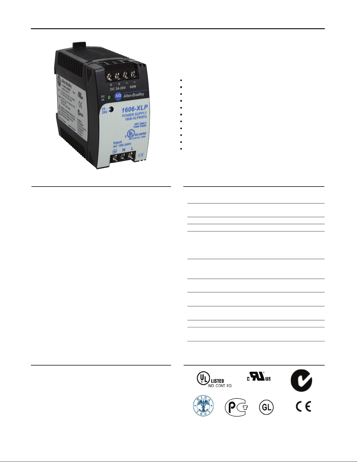
Bulletin 1606 Switched Mode Power Supplies
Power Supply
100-240V Wide Range Input
NEC Class 2 Compliant
Adjustable Output Voltage
Efciency up to 90.4%
Low No-load Losses and Excellent Partial-load Efciency
Compact Design, Width only 45mm
Electronic Inrush Current Limitation
Operation down to -40°C
Full Output Power up to +60°C
Large International Approval Package
3 Year Warranty
Description
Compact size, light weight, simple mounting onto the
DIN rail and the exclusive selection of quality components
are what makes this power supply so easy to install and
use within seconds.
A rugged electrical and mechanical design as well as a
high immunity against electrical disturbances on the
mains ensures reliable output power. This power supply
offers superior protection for equipment connected
to the public mains network or exposed to a critical
industrial environment.
This series of power supplies offers output voltages from
5 to 56Vdc and power ratings from 15W to 120W.
Principal characteristics of the 1606-XLP60EQT are the
electronic inrush current limitation and our power
supply's perfect suitability to very low ambient
temperatures. The unit is fully specied down to -40°C.
Specication Quick Reference
Output voltage DC 24V
Adjustment range 24 - 28V
Output current 2.5A at 24V
2.1A at 28V
Output power 60W
Output ripple < 50mVpp 20Hz to 20MHz
Input voltage AC 100-240V -15% / +10%
Mains frequency 50-60Hz ±6%
AC Input current 1.05 / 0.66A at 120 / 230Vac
Power factor 0.54 / 0.44 at 120 / 230Vac
AC Inrush current typ. 6A input voltage
and temperature
independent
DC Input 88-375Vdc below 100Vdc
derating required
Efciency 88.5 / 90.4% at 120 / 230Vac
Losses 7.8 / 6.4W at 120 / 230Vac
Temperature range -40°C to +70°C operational
Derating 1.5W/°C +60 to +70°C
Hold-up time typ. 24 / 107ms at 120 / 230Vac
Dimensions 45x75x91mm WxHxD
Weight 250g / 0.55lb
Catalog Numbers
Power Supply 1606-XLP60EQT 24-28V Standard unit
Accessory 1606-XLSBUFFER24 Buffer Module
Certication Marks
UL 508
UL 60950-1
NEC Class 2
Marine
EMC, LVD, RoHS
GOST R
Marine RINA
C-TICK
All parameters are specified at 24V, 2.5A, 230Vac input, 25°C ambient and after a 5 minutes run-in time, unless noted otherwise.
2 Rockwell Automation Publication 1606-RM014A-EN-P — March 2014
Page 3
Bulletin 1606 Switched Mode Power Supplies
1. Intended Use
• This device is designed for installation in an enclosure and is intended for the general professional use such as in industrial control, office,
communication, and instrumentation equipment.
• Do not use this power supply in equipment where malfunction may cause severe personal injury or threaten human life.
2. Installation Requirements
• This device may only be installed and put into operation by qualified personnel.
• This device does not contain serviceable parts. The tripping of an internal fuse is caused by an internal defect.
• Should damage or malfunction occur during installation or operation, immediately turn power off and send unit to the factory for inspection.
• Mount the unit on a DIN rail so that the input terminals are located on the bottom of the unit. For other mounting orientations, refer to derating
requirements in this document.
• This device is designed for convection cooling and does not require an external fan. Do not obstruct airflow and do not cover ventilation grid
(e.g. cable conduits) by more than 30%!
• Keep the following installation clearances: 40mm on top, 20mm on the bottom, 0mm on the left and right sides. Increase this clearance to
15mm in case the adjacent device is a heat source (e.g. another power supply).
SHOCK HAZARD: Do not use the power supply without proper grounding (Protective Earth). Use the terminal on the input
block for earth connection and not one of the screws on the housing.
- Turn power off before working on the device. Protect against inadvertent re-powering
- Make sure that the wiring is correct by following all local and national codes
- Do not modify or repair the unit
- Do not open the unit as high voltages are present inside
- Use caution to prevent any foreign objects from entering the housing
- Do not use in wet locations or in areas where moisture or condensation can be expected
- Do not touch during power-on, and immediately after power-off. Hot surfaces may cause burns.
WARNING: EXPLOSION HAZARDS!
Substitution of components may impair suitability for this environment. Do not disconnect the unit or operate the voltage adjustment or S/P jumper unless
power has been switched off or the area is known to be non-hazardous.
All parameters are specified at 24V, 2.5A, 230Vac input, 25°C ambient and after a 5 minutes run-in time unless noted otherwise.
Rockwell Automation Publication 1606-RM014A-EN-P — March 2014 3
Page 4
Bulletin 1606 Switched Mode Power Supplies
3. AC Input
AC input nom. AC 100-240V -15% / +10%, TN/TT/IT-mains
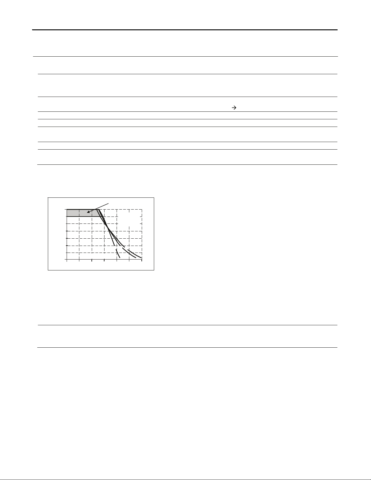
AC input range
85-264Vac continuous operation, reduce output power linearly to
50W between 90Vac and 85Vac at ambient
temperatures above +45°C, see Fig. 3-5
264–300Vac < 0.5s
Allowed voltage L or N to earth max. 264Vac or 375Vdc
Input frequency nom. 50–60Hz ±6%
Turn-on voltage typ. 75Vac steady-state value, see Fig. 3-1
Shut-down voltage typ. 65Vac steady-state value, see Fig. 3-1
AC 100V AC 120V AC 230V
Input current (rms) typ. 1.24A 1.05A 0.66A at 24V, 2.5A see Fig. 3-5
Power factor *) typ. 0.56 0.54 0.44 at 24V, 2.5A see Fig. 3-4
Crest factor **) typ. 3.4 3.7 4.0 at 24V, 2.5A
Start-up delay typ. 170ms 110ms 90ms see Fig. 3-2
Rise time typ. 50ms 50ms 60ms at 24V, 2.5A, 0mF, see Fig. 3-2
120ms 110ms 140ms at 24V, 2.5A, 2.5mF
Turn-on overshoot max. 200mV 200mV 200mV see Fig. 3-2
*) The power factor is the ratio of the true (or real) power to the apparent power in an AC circuit.
**) The crest factor is the mathematical ratio of the peak value to RMS value of the input current waveform.
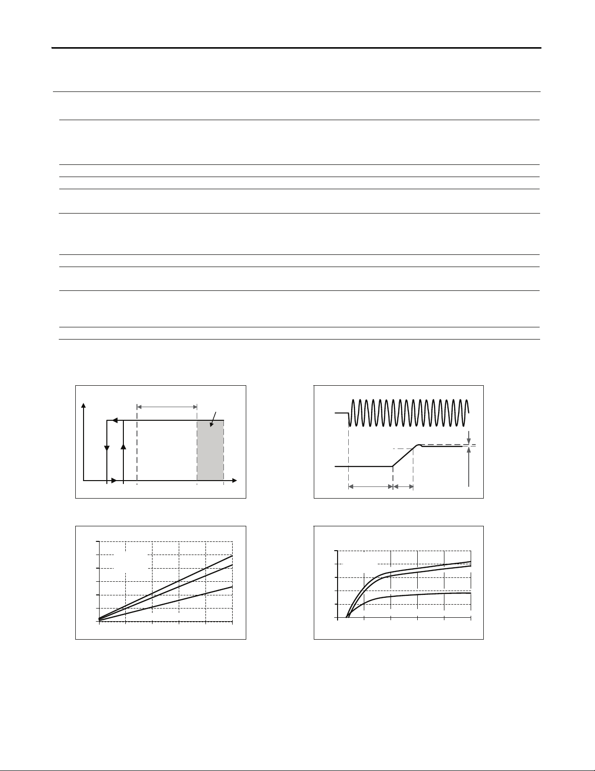
Fig. 3-1 Input voltage range Fig. 3-2 Turn-on behavior, denitions
Turn-on
85V
Rated
input range
max.
500ms
V
IN
V
OUT
65V 300Vac264V
Shut-down
75V
Start-up
delay
Rise
Time
Overshoot
- 5%
Output
Voltage
Input
Voltage
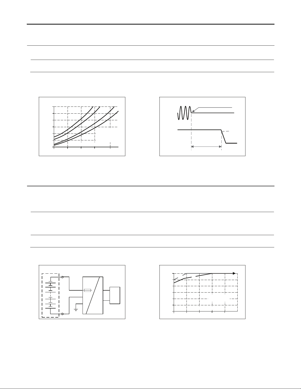
Fig. 3-3 Input current vs. output load at 24V Fig. 3-4 Power factor vs. output load at 24V
2.5A
0.5 1.50
0
0.5
1.5A
Input Current, typ.
2.0
1.0
1.0
1.25
0.75
0.25
b
c
a
a) 100Vac
b) 120Vac
c) 230Vac
Output Current
2.5A
0 0.5 1.0 2.0
0.35
0.40
0.45
0.50
0.55
0.60
Power Factor, typ.
a) 100Vac
b) 120Vac
c) 230Vac
b
c
a
1.5
Output Current
All parameters are specified at 24V, 2.5A, 230Vac input, 25°C ambient and after a 5 minutes run-in time unless noted otherwise.
4 Rockwell Automation Publication 1606-RM014A-EN-P — March 2014
Page 5
Bulletin 1606 Switched Mode Power Supplies
Allowable
Output Power
60W
50
40
30
20
10
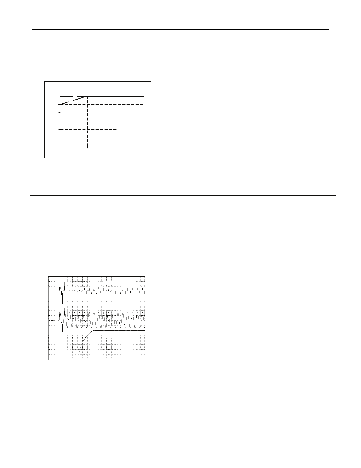
Fig. 3-5 De-rating requirements for
0
85Vac
low input voltages
A
B
90Vac
A
B
Input Voltage
.
<
.
.
+
5
4
C
°
.
.
<
.
+
0
6
°
C
4. Input Inrush Current
An electronic inrush current circuit limits the input inrush current after turn-on of the input voltage. The inrush current
is input voltage and ambient temperature independent.
The charging current into EMI suppression capacitors is disregarded in the rst microseconds after switch-on.
Inrush current max. 8A
typ. 6A
Inrush energy max. 0.2A
AC 100V AC 120V AC 230V
8A
peak
6A
peak
2
s 0.2A2s 0.3A2s between -40°C and +70°C
8A
peak
6A
peak
Fig. 4-1 Input inrush current, typical behavior
Input Current
peak
peak
between -40°C and +70°C
between -40°C and +70°C
Input Voltage
Output Voltage
Input: 230Vac
Output: 24V, 2.5A
Ambient: 25°C
Upper curve: Input current 2A/DIV
Middle curve: Input voltage 200V/DIV
Lower curve: Output voltage 5V/DIV
Time basis: 20ms / DIV
All parameters are specified at 24V, 2.5A, 230Vac input, 25°C ambient and after a 5 minutes run-in time unless noted otherwise.
Rockwell Automation Publication 1606-RM014A-EN-P — March 2014 5
Page 6
Bulletin 1606 Switched Mode Power Supplies
5. Output
Output voltage nom. 24V
Adjustment range min. 24-28V guaranteed
max. 30V *) at clockwise end position of potentiometer *)
Factory setting 24.5V ±0.2%, at full load, cold unit
Line regulation max. 10mV 85-264Vac
Load regulation max. 100mV static value, 0A 2.5A
Ripple and noise voltage max. 50mVpp 20Hz to 20MHz, 50Ohm
Output capacitance typ. 1 600μF
Output current nom. 2.5A at 24V, see Fig. 5-1
nom. 2.1A at 28V, see Fig. 5-1
Output power nom. 60W
Short-circuit current min. 3.6A load impedance 400mOhm, see Fig. 5-1
max. 6.2A load impedance 400mOhm, see Fig. 5-1
*) This is the maximum output voltage which can occur at the clockwise end position of the potentiometer due to tolerances. There is no
guarantee this value will be achieved. The typical value is about 28.6V.
Fig. 5-1 Output voltage vs. output current,
typ.
Output Voltage
0
0
4
8
12
28V
16
20
24
6A54
Adjustment
Range
Output Current
a) 100Vac
b) 120Vac
c) 230Vac
b
c
a
Peak current capability (up to several milliseconds)
The power supply can deliver a peak current which is higher than the specied short term current. This helps to start
current demanding loads or to safely operate subsequent circuit breakers.
The extra current is supplied by the output capacitors inside the power supply. During this event, the capacitors will be
discharged and causes a voltage dip on the output. Detailed curves can be found in section 21.1.
Peak current voltage dips typ. from 24V to 16V at 5A for 50ms, resistive load
typ. from 24V to 15V at 12.5A for 2ms, resistive load
typ. from 24V to 10.5V at 12.5A for 5ms, resistive load
123
6 Rockwell Automation Publication 1606-RM014A-EN-P — March 2014
All parameters are specified at 24V, 2.5A, 230Vac input, 25°C ambient and after a 5 minutes run-in time unless noted otherwise.
Page 7
Bulletin 1606 Switched Mode Power Supplies
6. Hold-up Time
AC 100V AC 120V AC 230V
Hold-up Time typ. 36ms 54ms 218ms at 24V, 1.25A, see Fig. 6-1
typ. 15ms 24ms 107ms at 24V, 2.5A, see Fig. 6-1
Note:
At no load, the hold-up time can be up to several seconds. The green DC-ok lamp is also on during this time
Fig. 6-1 Hold-up time vs. input voltage Fig. 6-2 Shut-down behavior, denitions
0
20
40
100
120ms
85 120 155 190 230Vac
Input Voltage
Hold-up Time
60
80
a) 24V 1.25A typ.
b) 24V 1.25Amin.
c) 24V 2.5A typ.
d) 24V 2.5A min.
a b c
d
- 5%
Hold-up Time
Zero Transition
Output
Voltage
Input
Voltage
7. DC Input
The power supply can also be supplied from a DC source. Use a battery or similar DC source. For other sources, contact
RA. Connect the + pole to L and the – pole to N. Connect the PE terminal to an earth wire or to the machine ground.
DC input nom. DC 110-300V -20%/+25%
DC input range min. 88-375Vdc continuous operation, reduce output power according
Fig. 7-2 at voltages below 110Vdc
Allowed Voltage L/N to Earth max. 375Vdc IEC 62103
DC input current typ. 0.62A / 0.22A 110Vdc / 300Vdc, at 24V, 2.5A
Turn-on voltage typ. 90Vdc steady state value
Shut-down voltage typ. 57Vdc similar behavior as shown in Fig. 3-1
Fig. 7-1 Wiring for DC Input
Fig. 7-2 Allowable output current below
110Vdc input voltage
+
-
Load
L
N
PE
+
-
Power Supply
AC
DC
Battery
internal
fused
0
10
20
30
40
60W
80 90 100 110 130Vdc
Input Voltage Vdc
Output Power
50
120
(
b
)
(
a
)
(a) Continuous
(b) Short-term
All parameters are specified at 24V, 2.5A, 230Vac input, 25°C ambient and after a 5 minutes run-in time unless noted otherwise.
Rockwell Automation Publication 1606-RM014A-EN-P — March 2014 7
Page 8
Bulletin 1606 Switched Mode Power Supplies
8. Efciency and Power Losses
AC 100V AC 120V AC 230V
Efciency typ. 87.4% 88.5% 90.4% at 24V, 2.5A (full load)
Power losses typ. 0.45W 0.5W 0.85W at 0A
typ. 3.9W 3.7W 3.9W at 24V, 1.25A (half load)
typ. 8.6W 7.8W 6.4W at 24V, 2.5A (full load)
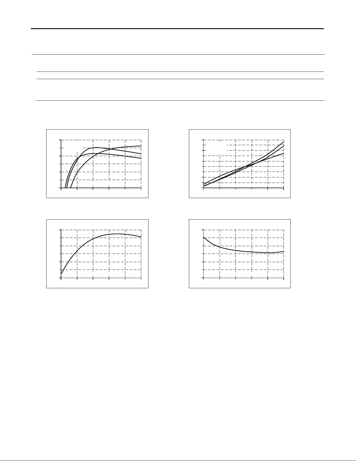
Fig. 8-1 Efciency vs. output current at 24V,
typ.
Fig. 8-2 Losses vs. output current at 24V,
typ.
Efciency
0
82
86
90
80
92%
2.5A0.5 1.5 2.0
Output Current
1.0
84
88
a) 230Vac
b) 120Vac
c) 100Vac
b
c
a
Power Losses
0
1
4
8
0
9W
2.5A0.5 1.5 2.0
Output Current
1.0
2
6
b
c
a
3
7
a) 230Vac
b) 120Vac
c) 100Vac
5
Fig. 8-3 Efciency vs. input voltage at 24V,
2.5A, typ.
Fig. 8-4 Losses vs. input voltage at 24V, 2.5A,
typ.
Efciency
85 120
155
190 225 260Vac
Input Voltage
91%
86
88
90
89
87
85
Power Losses
0
2
4
6
8
10
12W
85 120
155
190 225 260Vac
Input Voltage
8 Rockwell Automation Publication 1606-RM014A-EN-P — March 2014
All parameters are specified at 24V, 2.5A, 230Vac input, 25°C ambient and after a 5 minutes run-in time unless noted otherwise.
Page 9

9. Functional Diagram
Fig. 9-1 Functional diagram
Input Fuse
&
Input Filter
L
N
Output Over-
Voltage
Protection
Input
Rectier
&
Active
Inrush
Limiter
Power
Converter
Output
Voltage
Regulator
+
-
-
Output
Filter
+
V
OUT
DC
on
PE
10. Front Side and User Elements
Fig. 10-1 Front side
A
Output Terminals
Screw terminals,
Dual terminals for the negative and positive pole. Both poles are
equal
+ Positive output
- Negative (return) output
B
Input Terminals
Screw terminals
L Phase (Line) input
N Neutral conductor input
PE (Protective Earth) input
C
DC-on LED (green)
On, when the voltage on the output terminals is > 17V
D
Output voltage potentiometer
(single turn potentiometer)
Turn to set the output voltage. Factory set: 24.5V
C
D
B
Bulletin 1606 Switched Mode Power Supplies
All parameters are specified at 24V, 2.5A, 230Vac input, 25°C ambient and after a 5 minutes run-in time unless noted otherwise.
Rockwell Automation Publication 1606-RM014A-EN-P — March 2014 9
Page 10

Bulletin 1606 Switched Mode Power Supplies
11. Terminals and Wiring
All terminals are easy to access when mounted on the panel. Input and output terminals are separated from each
other (input below, output above) to help in error-free wiring.
Input Output
Type
screw terminals screw terminals
Solid wire 0.5-6mm2 0.5-6mm2
Stranded wire 0.5-4mm2 0.5-4mm2
American Wire Gauge 20-10 AWG 20-10 AWG
Wire stripping length 7mm / 0.275inch 7mm / 0.275inch
Screwdriver 3.5mm slotted or
Pozidrive No 2
3.5mm slotted or
Pozidrive No 2
Recommended tightening torque 1Nm, 9lb.in 1Nm, 9lb.in
Instructions:
a) Use appropriate copper cables that are designed for an operating temperature of:
60°C for ambient up to 45°C and 75°C for ambient up to 60°C minimum.
b) Follow national installation codes and installation regulations!
c) Ensure that all strands of a stranded wire enter the terminal connection!
d) Up to two stranded wires with the same cross section are permitted in one connection point (except PE wire).
e) Do not use the unit without PE connection.
f) Screws of unused terminal compartments should be securely tightened.
g) Ferrules are allowed.
h) Do not connect or disconnect the wires from the terminals below -25°C (-13°F).
12. Lifetime Expectancy and MTBF
These units are extremely reliable and use only the highest quality materials. The number of critical components such
as electrolytic capacitors has been reduced.
AC 100V AC 120V AC 230V
Lifetime expectancy
*) 50 000h 66 000h 90 000h at 24V, 2.5A and 40°C
122 000h 132 000h 104 000h at 24V, 1.25A and 40°C
142 000h *) 188 000h *) 255 000h *) at 24V, 2.5A and 25°C
MTBF
**) SN 29500, IEC 61709 1 292 000h 1 565 000h 1 866 000h at 24V, 2.5A and 40°C
2 343 000h 2 753 000h 3 216 000h at 24V, 2.5A and 25°C
MTBF
**) MIL HDBK 217F 772 000h 841 000h 861 000h at 24V, 2.5A , 40°C; Ground Benign GB40
1 029 000h 1 127 000h 1 167 000h at 24V, 2.5A , 25°C; Ground Benign GB25
176 000h 196 000h 213 000h at 24V, 2.5A , 40°C; Ground Fixed GF40
229 000h 256 000h 281 000h at 24V, 2.5A , 25°C; Ground Fixed GF25
*) The Lifetime expectancy shown in the table indicates the minimum operating hours (service life) and is determined by the lifetime
expectancy of the built-in electrolytic capacitors. Lifetime expectancy is specied in operational hours and is calculated according to the
capacitor’s manufacturer specication. The manufacturer of the electrolytic capacitors only guarantees a maximum life of up to 15 years
(131 400h). Any number exceeding this value is a calculated theoretical lifetime which can be used to compare devices.
**) MTBF stands for Mean Time Between Failure, which is calculated according to statistical device failures, and indicates reliability of a
device. It is the statistical representation of the likelihood of a unit to fail and does not necessarily represent the life of a product.
The MTBF gure is a statistical representation of the likelihood of a device to fail. A MTBF gure of e.g. 1 000 000h means that
statistically one unit will fail every 100 hours if 10 000 units are installed in the eld. However, it can not be determined if the failed unit
has been running for 50 000h or only for 100h.
10 Rockwell Automation Publication 1606-RM014A-EN-P — March 2014
All parameters are specified at 24V, 2.5A, 230Vac input, 25°C ambient and after a 5 minutes run-in time unless noted otherwise.
Page 11

Bulletin 1606 Switched Mode Power Supplies
13. EMC
The power supply is suitable for applications in industrial environment as well as in residential, commercial and light
industry environment without any restrictions. A detailed EMC report is available upon request.
EMC Immunity
Generic standards: EN 61000-6-1 and EN 61000-6-2
Electrostatic discharge EN 61000-4-2 Contact discharge
Air discharge
8kV
8kV
Criterion A
Criterion A
Electromagnetic RF eld EN 61000-4-3 80MHz-2.7GHz 10V/m Criterion A
Fast transients (Burst) EN 61000-4-4 Input lines
Output lines
4kV
2kV
Criterion A
Criterion A
Surge voltage on input EN 61000-4-5
L
N
N
PE, L PE
2kV
4kV
Criterion A
Criterion A
Surge voltage on output EN 61000-4-5 + -
+
PE, - PE
1kV
2kV
Criterion A
Criterion A
Conducted disturbance EN 61000-4-6 0.15-80MHz 10V Criterion A
Mains voltage dips EN 61000-4-11 0% of 100Vac
40% of 100Vac
70% of 100Vac
0% of 200Vac
40% of 200Vac
70% of 200Vac
0Vac, 20ms
40Vac, 200ms
70Vac, 500ms
0Vac, 20ms
80Vac, 200ms
140Vac, 500ms
Criterion A *)
Criterion C
Criterion A
Criterion A
Criterion A
Criterion A
Voltage interruptions EN 61000-4-11 0Vac, 5000ms Criterion C
Input voltage swells RA internal standard 300Vac, 500ms Criterion A
Powerful transients VDE 0160 over entire load range 750V, 1.3ms Criterion A
Criteria:
A: Power supply shows normal operation behavior within the dened limits.
B: The power supply operates continuously during and after the test. During the test minor temporary impairments may occur, which will be
corrected by the power supply itself.
C: Temporary loss of function is possible. Power supply may shut-down and restarts by itself. No damage or hazards for the power supply
will occur.
*) Up to 1.8A output current criterion A, above 1.8A output current criterion B
EMC Emission
Generic standards: EN 61000-6-3 and EN 61000-6-4
Conducted emission EN 55011, EN 55022, FCC Part 15, CISPR 11, CISPR 22 Class B, input lines
Radiated emission EN 55011, EN 55022, CISPR 11, CISPR 22 Class B
Harmonic input current EN 61000-3-2 Not applicable below 75W
input power
Voltage uctuations,
icker *)
EN 61000-3-3 Fullled
This device complies with FCC Part 15 rules.
Operation is subjected to following two conditions: (1) this device may not cause harmful interference, and (2) this
device must accept any interference received, including interference that may cause undesired operation.
*) tested with constant current loads, non pulsing
Switching frequency
Converter frequency variable, typ. 100kHz, min. 45kHz, max. 160kHz Input voltage and output
load dependent
All parameters are specified at 24V, 2.5A, 230Vac input, 25°C ambient and after a 5 minutes run-in time unless noted otherwise.
Rockwell Automation Publication 1606-RM014A-EN-P — March 2014 11
Page 12

Bulletin 1606 Switched Mode Power Supplies
14. Environment
Operational temperature
*) -40°C to +70°C (-40°F to 158°F) reduce output power according Fig. 14-1
Storage temperature -40°C to +85°C (-40°F to 185°F) for storage and transportation
Output de-rating 1.5W/°C 60-70°C (140°F to 158°F)
Humidity
**) 5 to 95% r.H. IEC 60068-2-30
Vibration sinusoidal 2-17.8Hz: ±1.6mm; 17.8-500Hz: 2g
2 hours / axis
IEC 60068-2-6
Shock 15g 6ms, 10g 11ms
3 bumps / direction, 18 bumps in total
IEC 60068-2-27
Altitude 0 to 2000m (0 to 6 560ft) without any restrictions
2000 to 6000m (6 560 to 20 000ft) reduce output power or ambient temperature
see Fig. 14-2
IEC 62103, EN 50178, overvoltage category II
Altitude de-rating 4W/1000m or 5°C/1000m > 2000m (6500ft), see Fig. 14-2
Over-voltage category III IEC 62103, EN 50178, altitudes up to 2000m
II altitudes from 2000m to 6000m
Degree of pollution 2 IEC 62103, EN 50178, not conductive
LABS compatibility The unit does not release any silicone or other LABS-critical substances and is suitable for
use in paint shops.
*) Operational temperature is the same as the ambient temperature and is dened as the air temperature 2cm below the unit.
Do not connect or disconnect the wires from the terminals below -25°C.
**) Do not energize in the presence of condensation.
Fig. 14-1 Output power vs. ambient temp. Fig. 14-2 Output power vs. altitude
0
-40 0 40
70°C
10
20
30
40
50
60W
60
A
.
.
.
f
o
r
A
C
2
3
0
V
m
a
i
n
s
B
.
.
.
f
o
r
A
C
1
2
0
V
m
a
i
n
s
C
.
.
.
f
o
r
A
C
1
0
0
V
m
a
i
n
s
-25-33
Ambient Temperature
Allowable
Output Power
A
C
B
0
0 2000 4000
6000m
10
20
30
40
50
60W
Altitude
A
.
.
.
T
a
m
b
<
6
0
°
C
B
.
.
.
T
a
m
b
<
5
0
°
C
C
.
.
.
T
a
m
b
<
4
0
°
C
A
B
C
Allowable
Output Power
12 Rockwell Automation Publication 1606-RM014A-EN-P — March 2014
All parameters are specified at 24V, 2.5A, 230Vac input, 25°C ambient and after a 5 minutes run-in time unless noted otherwise.
Page 13

Bulletin 1606 Switched Mode Power Supplies
15. Protection Features
Output protection Electronically protected against overload, no-load and short-circuits *)
Output over-voltage protection typ. 31Vdc
max. 32.5Vdc
In case of an internal power supply fault, a redundant
circuit limits the maximum output voltage. In such a
case, the output shuts down and stays down until the
input voltage is turned off and on again.
Output over-current protection electronically limited see Fig. 5-1
Degree of protection IP 20 EN/IEC 60529
Penetration protection > 2.5mm in diameter e.g. screws, small parts
Over-temperature protection Not included
Input transient protection MOV Metal Oxide Varistor
Internal input fuse T3.15A H.B.C. not user replaceable
*) In case of a protection event, audible noise may occur.
16. Safety Features
Input / output separation
*) SELV IEC/EN 60950-1
PELV IEC/EN 60204-1, EN 50178, IEC 62103, IEC 60364-4-41
Class of protection I PE (Protective Earth) connection required
II (with restrictions) for use without PE connection, contact RA.
Isolation resistance > 5MOhm Input to output, 500Vdc
Touch current (leakage current) typ. 0.13mA / 0.29mA 100Vac, 50Hz, TN-,TT-mains / IT-mains
typ. 0.19mA / 0.40mA 120Vac, 60Hz, TN-,TT-mains / IT-mains
typ. 0.30mA / 0.63mA 230Vac, 50Hz, TN-,TT-mains / IT-mains
< 0.17mA / 0.38mA 110Vac, 50Hz, TN-,TT-mains / IT-mains
< 0.25mA / 0.53mA 132Vac, 60Hz, TN-,TT-mains / IT-mains
< 0.41mA / 0.85mA 264Vac, 50Hz, TN-,TT-mains / IT-mains
*) Double or reinforced insulation
All parameters are specified at 24V, 2.5A, 230Vac input, 25°C ambient and after a 5 minutes run-in time unless noted otherwise.
Rockwell Automation Publication 1606-RM014A-EN-P — March 2014 13
Page 14

Bulletin 1606 Switched Mode Power Supplies
17. Dielectric Strength
The output voltage is oating and has no ohmic connection to the ground. Type and factory tests are conducted by
the manufacturer. Field tests may be conducted in the eld using the appropriate test equipment which applies the
voltage with a slow ramp (2s up and 2s down). Connect all phase-terminals together as well as all output poles before
conducting the test. When testing, set the cut-off current settings to the value in the table below.
Fig. 17-1 Dielectric strength
A B C
Type test 60s 2500Vac 4000Vac 2000Vac
Factory test 5s 2500Vac 2500Vac 500Vac
Field test 5s 2000Vac 2000Vac 500Vac
Cut-off current setting > 4mA > 4mA > 1mA
A
C
N
L
Input
Earth, PE
Output
-
+
B
To fulll the PELV requirements according to EN 60204-1 § 6.4.1,
we recommend that either the + pole, the – pole or any other part
of the output circuit shall be connected to the protective earth
system. This helps to avoid situations in which a load starts
unexpectedly or can not be switched off when unnoticed earth
faults occur.
All parameters are specified at 24V, 2.5A, 230Vac input, 25°C ambient and after a 5 minutes run-in time unless noted otherwise.
14 Rockwell Automation Publication 1606-RM014A-EN-P — March 2014
Page 15
Bulletin 1606 Switched Mode Power Supplies
18. Certications
EC Declaration of
Conformity
UL 508
UL 60950-1
nd
2
Edition
NEC Class 2
Marine GL GL (Germanischer Lloyd) classied for marine and offshore
Marine Rina
NEC
CLASS 2
Complies with
- CE EMC directive
- CE Low-voltage directive
Listed E56639 for use in the U.S.A. (UL 508) and Canada
(C22-2 No. 19-45). Industrial Control Equipment
RECOGNIZED E168663 for use in the U.S.A. (UL 60950-1)
and Canada (C22.2 No. 60950)
Information Technology Equipment, Level 3
Listed as Limited Power Source (LPS) in the UL 60950-1 UL report.
According to NEC (National Electrical Code) Article 725-41 (4).
applications. Environmental category: C, EMC2. See below for link
to the certicate.
RINA (Registro Italiano Navale) certied. See below for the link to
the certicate.
GOST R
C-TICK
GOST R certication is applicable for products intended for sale
and use within Russia. See below for link to Certicate.
C-tick compliance is for products intended for sale and use within
the Australian market. See below for the link to the C-tick
Declarations of Conformity.
Product certification (including Certificates and Declarations of Conformity) can be found at www.ab.com/certification/.
All parameters are specified at 24V, 2.5A, 230Vac input, 25°C ambient and after a 5 minutes run-in time unless noted otherwise.
Rockwell Automation Publication 1606-RM014A-EN-P — March 2014 15
Page 16

Bulletin 1606 Switched Mode Power Supplies
19. Physical Dimensions and Weight
Weight 250g / 0.55lb
DIN Rail Use 35mm DIN rails according to EN 60715 or EN 50022 with a height of 7.5 or 15mm.
The DIN rail height must be added to the unit depth (91mm) to calculate the total required
installation depth.
Installation Clearances See section 2
Fig. 20-1 Front view Fig. 20-2 Side view
All parameters are specified at 24V, 2.5A, 230Vac input, 25°C ambient and after a 5 minutes run-in time unless noted otherwise.
16 Rockwell Automation Publication 1606-RM014A-EN-P — March 2014
Page 17

Bulletin 1606 Switched Mode Power Supplies
20. Accessory
20.1. 1606-XLSBUFFER24 Buffer Module
This buffer unit is a supplementary device for DC 24V power supplies. It delivers power to bridge typical mains failures
or extends the hold-up time after turn-off of the AC power. In times when the
power supply provides sufcient voltages, the buffer module stores energy in
integrated electrolytic capacitors. In case of mains voltage fault, this energy is
released again in a regulated process. One buffer module can deliver 20A which can
also be used to support peak current demands.
The buffer unit does not require any control wiring.
It can be added in parallel to the load circuit at any
given point. Buffer units can be added in parallel to
increase the output ampacity or the hold-up time.
DC
Buffer
Unit(s)
Power
Supply
Load
AC
+
-
All parameters are specified at 24V, 2.5A, 230Vac input, 25°C ambient and after a 5 minutes run-in time unless noted otherwise.
Rockwell Automation Publication 1606-RM014A-EN-P — March 2014 17
Page 18
Bulletin 1606 Switched Mode Power Supplies
21. Application Notes
21.1. Peak Current Capability
Solenoids, contactors and pneumatic modules often have a steady state coil and a pick-up coil. The inrush current
demand of the pick-up coil is several times higher than the steady-state current and usually exceeds the nominal
output current. The same situation applies when starting a motor or switching-on a capacitive load.
In many cases, the peak current capability also ensures a safe operation of subsequent circuit breakers. Branch circuits
are often protected with circuit breakers or fuses. In case of a short or an overload in a branch circuit, the fuse needs a
certain amount of over-current to trip or to blow.
Assuming the input voltage is turned on before such an event, the built-in large sized output capacitors inside the
power supply can deliver extra current. Discharging this capacitor causes a voltage dip on the output. The following
two examples show typical voltage dips:
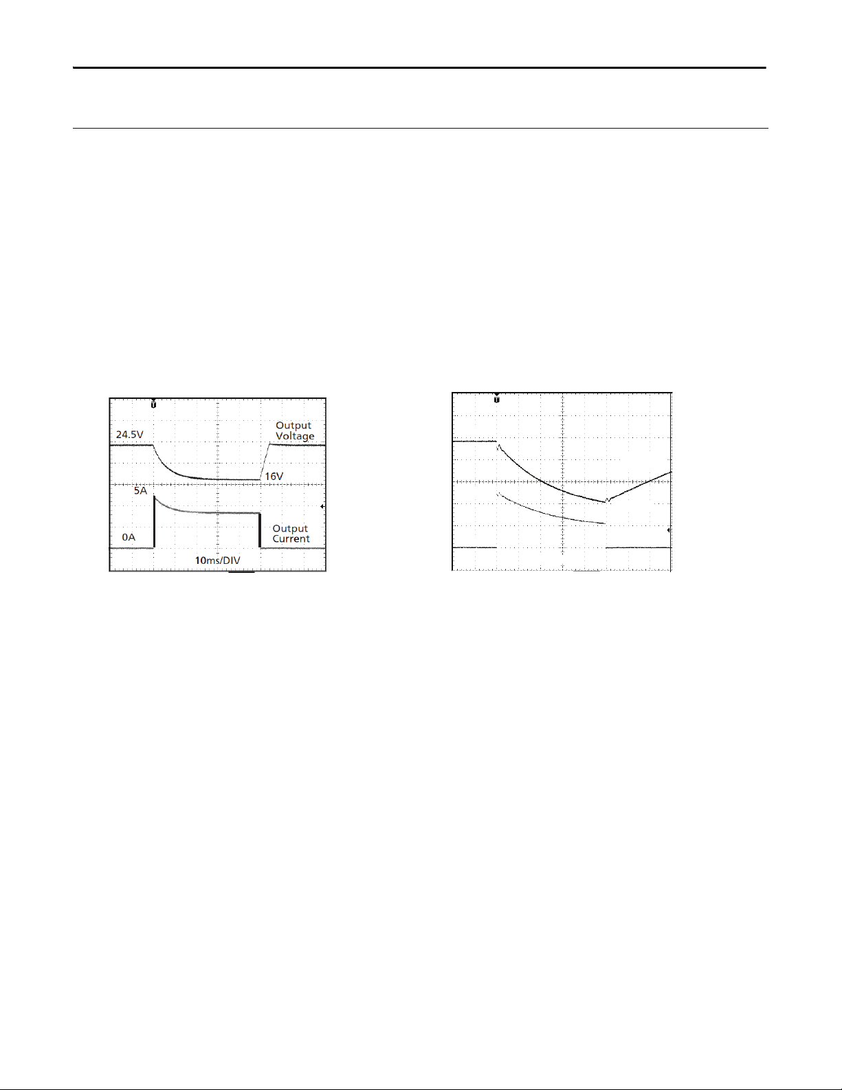
Fig. 21-1 Peak loading with 2x the nominal
current for 50ms, typ.
Fig. 21-2 Peak loading with 5x the nominal
current for 5ms, typ.
1ms/DIV
Output
Voltage
Output
Current
24.5V
0A
12.5A
10.5V
Peak load 5A (resistive load) for 50ms
Output voltage dips from 24V to 16V.
Peak load 12.5A (resistive load) for 5ms
Output voltage dips from 24V to 10.5V.
21.2. Back-feeding Loads
Loads such as decelerating motors and inductors can feed voltage back to the power supply. This feature is also called
return voltage immunity or resistance against Back- E.M.F. (Electro Magnetic Force).
This power supply is resistant and does not show malfunctioning when a load feeds back voltage to the power supply.
It does not matter whether the power supply is on or off.
The maximum allowed feed-back-voltage is 35Vdc. The absorbing energy can be calculated according to the built-in
large sized output capacitor which is specied in section 5.
18 Rockwell Automation Publication 1606-RM014A-EN-P — March 2014
All parameters are specified at 24V, 2.5A, 230Vac input, 25°C ambient and after a 5 minutes run-in time unless noted otherwise.
Page 19

Bulletin 1606 Switched Mode Power Supplies
21.3. Charging Batteries
The power supply can be used to charge lead-acid or maintenance free batteries. (Two 12V batteries in series)
Instructions for charging batteries (oat charging):
a) Ensure that the ambient temperature of the power supply is below 45°C
b) Set output voltage (measured at no load and at the battery end of the cable) very precisely to the end-of-charge
voltage.
End-of-charge voltage 27.8V 27.5V 27.15V 26.8V
Battery temperature 10°C 20°C 30°C 40°C
c) Use a 4A circuit breaker (or blocking diode) between the power supply and the battery.
d) Ensure that the output current of the power supply is below the allowed charging current of the battery.
e) Use only matched batteries when putting 12V types in series.
f) The return current to the power supply (battery discharge current) is typical 7.3mA when the power supply is
switched off (except in case a blocking diode is utilized).
21.4. External Input Protection
The unit is tested and approved for branch circuits up to 20A. An external protection is only required, if the supplying
branch has an ampacity greater than this. Check also local codes and local requirements. In some countries local
regulations might apply.
If an external fuse is necessary or utilized, minimum requirements need to be considered to avoid nuisance tripping of
the circuit breaker. A minimum value of 6A B- or 3A C-Characteristic breaker should be used.
21.5. Parallel Use to Increase Output Power
1606-XLP60EQT power supplies may be used in parallel to increase output power.
This power supply does not include any feature included that balances the load
current between the power supplies. Usually the power supply with the higher
adjusted output voltage draws current until it goes into current limitation. This
causes no harm to the power supply as long as the ambient temperature stays
below 45°C. The 1606-XLP60EQT can also be used in parallel with other, similar
power supplies with 24V output voltage. The output voltages of all power supplies
need to be adjusted to the same value (±100mV). A fuse or diode on the
output of each unit is required only if more than three units are connected in parallel. If you use a fuse or circuit
breaker, choose one with approximately 150% of the rated output current of one power supply. Keep an
installation clearance of 15mm (left / right) between two power supplies and avoid installing the power supplies on
top of each other. Do not use power supplies in parallel in mounting orientations other than the standard mounting
orientation (input terminals on the bottom and output terminals on top of the unit). Be aware that leakage current,
EMI, inrush current and harmonics will increase when using multiple power supplies in parallel.
Unit A
AC
DC
Unit B
AC
DC
-
+
-
+
Load
+
-
All parameters are specified at 24V, 2.5A, 230Vac input, 25°C ambient and after a 5 minutes run-in time unless noted otherwise.
Rockwell Automation Publication 1606-RM014A-EN-P — March 2014 19
Page 20

Bulletin 1606 Switched Mode Power Supplies
21.6. Daisy Chaining of Outputs
Daisy chaining (jumping from one power supply output to the next) is allowed as long as the average output current
through one terminal pin does not exceed 25A. If the current is higher, use a separate distribution terminal block.
Fig. 21-3 Daisy chaining of outputs Fig. 21-4 Using distribution terminals
max 25A!
+
Load
-
Output
+ +
- -
Power
Supply
Output
+ +
- -
Power
Supply
+
Load
-
Output
+ +
- -
Output
+ +
- -
Power
Supply
Power
Supply
Input
Input
Input
Input
Distribution
Terminals
21.7. Inductive and Capacitive Loads
The unit is designed to supply any type of load, including unlimited capacitive and inductive loads.
All parameters are specified at 24V, 2.5A, 230Vac input, 25°C ambient and after a 5 minutes run-in time unless noted otherwise.
20 Rockwell Automation Publication 1606-RM014A-EN-P — March 2014
Page 21

Bulletin 1606 Switched Mode Power Supplies
21.8. Series Operation
Power supplies of the exact same type can be connected in series for higher
output voltages. It is possible to connect as many units in series as needed,
providing the sum of the output voltage does not exceed 150Vdc. Voltages
with a potential above 60Vdc are not SELV any more and can be dangerous.
Such voltages must be installed with a protection against touching. Grounding of
the output is required when the sum of the output voltage exceeds 60Vdc.
Avoid return voltage (e.g. from a decelerating motor or battery) which is
applied to the output terminals. Keep an installation clearance of 15mm (left /
right) between two power supplies and do not install the power supplies on
top of each other. Do not use power supplies in series in mounting
orientations other than the standard mounting orientation (input terminals on the bottom and output terminals on
top of the unit). Be aware that leakage current, EMI, inrush current and harmonics will increase when using multiple
power supplies in series.
Earth
Unit A
AC
DC
Unit B
AC
DC
-
+
-
+
Load
+
-
21.9. Operation on Two Phases
240V
+10%
max.
Fuse
L2
L1
L3
L
N
PE
Power Supply
AC
DC
internal
fuse
The power supply can also be used on two-phases of a three-phase-system.
A phase-to-phase connection is allowed as long as the supplying voltage is
below 240V
+10%
. Use a fuse or a circuit breaker to protect the N input. The
N input is not internally protected and is in this case connected to a hot
wire. Appropriate fuses or circuit breakers are specied in section 21.4
“External Input Protection”.
21.10. Use Without PE on the Input
From a safety standpoint, the unit is internally designed according to the requirements for Protection Class 1 and 2.
Please contact RA if you don't intend to use the PE terminal. A different marking of the front foil is then required.
Grounding of the input is benecial for a high EMI immunity: symmetrical spikes or fast transients on the input side
can be conducted directly to earth by the built-in lter capacitors. The magnitude of such spikes or fast transients on
the output side caused by the input is much smaller than if you're not connecting this terminal to ground.
Fig. 21-5 Grounded input Fig. 21-6 Ungrounded input
Surge
Y
X
L
N
Ground
Power Supply
+
-
Surge
X
L
N
Power Supply
+
-
24V
Spike
All parameters are specified at 24V, 2.5A, 230Vac input, 25°C ambient and after a 5 minutes run-in time unless noted otherwise.
Rockwell Automation Publication 1606-RM014A-EN-P — March 2014 21
Page 22

Bulletin 1606 Switched Mode Power Supplies
21.11. Use at Low Temperatures (-25°C / -40°C)
Please pay attention to the following aspects when operating the unit at low temperatures. Perform tests to verify
suitability in your application.
- The ripple & noise voltage will increase. For the rst minutes after turning on the unit at -40°C, the ripple an
noise voltage can be up to typically 400mVpp depending on load and input voltage. Once the unit heats up,
the ripple & noise voltage will decrease typically to 90mVpp.
- The start-up delay can be up to 5 seconds. It is a continuous turn-on process without any voltage dips or startup attempts.
21.12. Use in a Tightly Sealed Enclosure
When the power supply is installed in a tightly sealed enclosure, the temperature inside the enclosure will be higher
than outside. In such situations, the inside temperature denes the ambient temperature for the power supply.
The following measurement results can be used as a reference to estimate the temperature rise inside the enclosure.
The power supply is placed in the middle of the box; no other heat producing item is inside the box.
Enclosure: Rittal Type IP66 Box PK 9510 100, plastic, 130x130x75mm
Input: 230Vac
Case A:
Load: 24V, 2.5A; load is placed outside the box
Temperature inside the box: 40.3°C (in the middle of the right side of the power supply with a distance of 1cm)
Temperature outside the box: 21.8°C
Temperature rise: 18.5K
Case B:
Load: 24V, 2.0A; (=80%) load is placed outside the box
Temperature inside the box: 38.6°C (in the middle of the right side of the power supply with a distance of 1cm)
Temperature outside the box: 22.1°C
Temperature rise: 16.5K
All parameters are specified at 24V, 2.5A, 230Vac input, 25°C ambient and after a 5 minutes run-in time unless noted otherwise.
22 Rockwell Automation Publication 1606-RM014A-EN-P — March 2014
Page 23

Bulletin 1606 Switched Mode Power Supplies
21.13. Mounting Orientations
Mounting orientations other than input terminals on the bottom and output on the top require a reduction in
continuous output power or a limitation in the maximum allowed ambient temperature. The amount of reduction
inuences the lifetime expectancy of the power supply. Therefore, two different derating curves for continuous
operation can be found below:
Curve A1 Recommended output current.
Curve A2 Max allowed output current (results in approximately half the lifetime expectancy of A1).
Fig. 21-7
Mounting
Orientation A
(Standard
orientation)
Fig. 21-8
Mounting
Orientation B
(Upside down)
OUTPUT
Power
Supply
INPUT
INPUT
Supply
Power
OUTPUT
Fig. 21-9
Mounting
Orientation C
(Table-top
mounting)
Fig. 21-10
Mounting
Orientation D
(Horizontal cw)
Supply
INPUT
Power
OUTPUT
Fig. 21-11
Mounting
Orientation E
(Horizontal ccw)
Power
OUTPUT
INPUT
Supply
Output Power
60W
48
36
24
12
0
Ambient Temperature
10 20 30 40
Output Power
60W
48
36
24
12
0
Ambient Temperature
10 20 30 40
Output Power
60W
48
36
24
12
0
Ambient Temperature
10 20 30 40
Output Power
60W
48
36
24
12
0
Ambient Temperature
10 20 30 40
Output Power
60W
48
36
24
12
0
Ambient Temperature
10 20 30 40
50
50
50
50
50
A
1
60°C
A
2
A
1
60°C
2
A
A
1
60°C
A
2
A
1
60°C
A
2
1
A
60°C
All parameters are specified at 24V, 2.5A, 230Vac input, 25°C ambient and after a 5 minutes run-in time unless noted otherwise.
Rockwell Automation Publication 1606-RM014A-EN-P — March 2014 23
Page 24

Rockwell Automation Support
Rockwell Automation provides technical information on the Web to assist you in using its products.
At http://www.rockwellautomation.com/support
notes, sample code and links to software service packs, and a MySupport feature that you can customize to
make the best use of these tools. You can also visit our Knowledgebase at http://
www.rockwellautomation.com/knowledgebase for FAQs, technical information, support chat and forums,
software updates, and to sign up for product notification updates.
, you can find technical manuals, technical and application
For an additional level of technical phone support for installation, configuration, and troubleshooting, we offer
Tech Con ne ct
representative, or visit http://www.rockwellautomation.com/support/
SM
support programs. For more information, contact your local distributor or Rockwell Automation
.
Installation Assistance
If you experience a problem within the first 24 hours of installation, review the information that is contained in
this manual. You can contact Customer Support for initial help in getting your product up and running.
United States or Canada 1.440.646.3434
Outside United States or Canada Use the Wor ldwi de Lo cato r at http://www.rockwellautomation.com/rockwellautomation/support/overview.page, or contact your local
Rockwell Automation representative.
New Product Satisfaction Return
Rockwell Automation tests all of its products to help ensure that they are fully operational when shipped from
the manufacturing facility. However, if your product is not functioning and needs to be returned, follow these
procedures.
United States Contact your distributor. You must provide a Customer Support case number (call the phone number above to obtain one) to your
Outside United States Please contact your local Rockwell Automation representative for the return procedure.
distributor to complete the return process.
Documentation Feedback
Your comments will help us serve your documentation needs better. If you have any suggestions on how to
improve this document, complete this form, publication RA-DU002
literature.rockwellautomation.com/idc/groups/literature/documents/du/ra-du002_-en-e.pdf.
Publication 1606-RM014A-EN-P — March 2014
, available at http://
Copyright © 2014 Rockwell Automation, Inc. All rights reserved. Printed in the U.S.A.
 Loading...